1
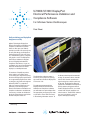
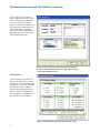
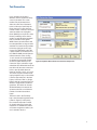
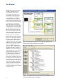
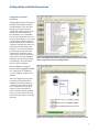
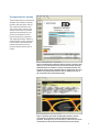
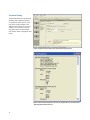
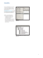
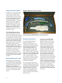
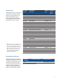
U7232B/U7232C DisplayPort
Electrical Performance Validation and
Compliance Software
For Infiniium Series Oscilloscopes
Data Sheet
Verify and debug your DisplayPort
designs more easily
Agilent Technologies DisplayPort
Electrical Performance Validation and
Compliance software for Infiniium
Series oscilloscopes (see Table 2)
provides you with a fast and easy way
to verify and debug your DisplayPort
interface designs for sink and source
ICs, motherboard systems, computers
and graphics cards. The DisplayPort
electrical test software is designed
for use in DisplayPort Authorized
Compliance Test Houses, so you can
confidently use it to execute DisplayPort
electrical checklist tests as well as
employ it as a development tool.
To introduce a DisplayPort product
to the market, your product must
successfully pass compliance testing
based on the DisplayPort specification
at an approved DisplayPort test center
or through a self certification regimen
defined by VESA1 in cooperation
with your company. Either way, you
will want to use the DisplayPort
Electrical Performance Validation and
Compliance software to troubleshoot,
if necessary, and then to validate the
design by performing the tests before
the final compliance test run.
1 Video Electronics Standards Association
(www.vesa.org)
The DisplayPort software makes it
easier for you to prepare for passing
the certification hurdle for DisplayPort
CTS version 1.2b.
To make measurements with the
DisplayPort Electrical Performance
Validation and Compliance software,
you will need a test point adapter with
the appropriate connector type to mate
to your device. These TPAs are listed
in the ordering information section. To
facilitate productivity with unattended
testing, an automatic device controller
with an AUX channel controller and
signal routing into a switch matrix may
be desired. The DisplayPort Electrical
Performance Validation and Compliance
(EPVC) software will operate with all
vendors’ DisplayPort TPAs, can control
several AUX channel controllers and
switch matrices. The DP EPVC software
puts you in the driver’s seat in all
aspects of DisplayPort testing.
DisplayPort compliance software helps you do the right job faster
Features
Save time
Easy test definition
The DisplayPort electrical test software
is a full-featured package to simplify
the validation process of DisplayPort
designs:
The DisplayPort Electrical Performance
Validation and Compliance software
saves you time by setting the
stage for automatic execution of
DisplayPort electrical tests. Part of
the difficulty of performing electrical
tests for DisplayPort is connecting
the oscilloscope to the target device,
configuring the instrument for
measurements, executing the test
procedures, defining the capabilities
of the device under test, and then
analyzing the measured results by
comparing them to limits published
in the specification. The DisplayPort
electrical test software does almost all
of this work for you. In addition, if you
discover a problem with your device,
debug tools are available to aid in rootcause analysis.
The DisplayPort Electrical Performance
Validation and Compliance software
extends the ease-of-use advantages of
Agilent’s Infiniium Series oscilloscopes
to testing DisplayPort designs. The
Agilent automated test engine walks
you quickly through the steps required
to define the device under test, to
select the tests, set up the tests,
perform the tests, and view the test
results. You can pick high-level test
parameters to suit your test process
objectives, and then you can proceed
to select a category of tests all at
once, or specify individual tests. The
user interface is oriented to minimize
reconnections, which saves you
time and minimizes potential for
operator error. You can save tests
and configurations as project files
and recall them later for quick testing
and review of previous test results.
Straightforward menus let you perform
tests with a minimum of mouse clicks.
• Full Physical Layer Testing High
speed Lanes and AUX channel
• Full physical layer testing of AUX
channels
• Support of multiple CTS versions
• Test Status tracking
• Support of eDP 1.3
• Support of MyDP/SlimPort (SlimPort
is a trademarked implementation of
MyDP by Analogix)
• Measurement process
configurability
• Support of DualMode, or DP++
• Automated scope measurement
setup
• Test results reports with pass/fail
margin analysis
• Automation control through AUX
Channel Controller
• Optional switch control
With the DisplayPort electrical test
software, you can use the same
oscilloscope you use for everyday
debugging to perform automated
testing and margin analysis based on
the DisplayPort-specified test checklist.
2
The DisplayPort software offers the
electrical tests for the source as
well as important tests for cable and
calibration for receiver tolerance
testing. The software automatically
configures the oscilloscope for each
test, and it provides an informative
results report that includes margin
analysis indicating how close your
product is to passing or failing that
specification. Clock recovery of each
lane is accomplished according to the
standard by the oscilloscope using
proprietary software techniques.
See Table 1 for a complete list of
the measurements made by the
DisplayPort electrical test software.
Further test process control is also
provided through the automation
tab of graphical user interface. This
tab allows the user to tailor scripts
to control external equipment such
as power supplies and temperature
control units, or to provide a different
test flow.
Test environment setup and test selection
The DisplayPort Electrical Performance
Validation and Compliance software
now allows you to define the DUT
capability and select test environment
variables to better suit your testing
goals for speed and cost. The setup
process begins with the Setup entry
screen (shown in Figure 1). This screen
enables selection of the DisplayPort
Compliance test specification (for
instance 1.1a or 1.2b as shown in
Figure 1) and test groupings for
hi-speed video lane testing (Physical
Layer Tests), AUX Channel and whole
device characteristics (AUX PHY
and Inrush Tests), or HDMI over the
DisplayPort interface (DualMode
tests). This screen will also let
you choose between exposing just
normative (mandatory) tests or all
tests: normative and informative. The
bottom portion of the environment
Set Up tab is dedicated to automation
through the AUX test mode. After
making the appropriate selections
for you testing, the setup continues
with DUT characteristics entry and
connection specifics when the Test
Setup button is selected.
The Test Setup loop presents a series
of screens that allow the user to
enter the key test and environment
information because there is a
wide range of test connections and
optional performance allowed for in
the DisplayPort specification. Some of
this test process information is briefly
described below.
Figure 1: DisplayPort Test Environment Setup
●
Device ID: enter the device name and other pertinent information
●
Operator ID: For compliance test houses to identify the operator for QA process.
●
Project ID: for compliance test houses that identify projects by number this enables the report to carry a key identification number to a contract.
●
Device Type: allows you to select between cable test, sink test
and source test suite. The most common selection is source testing.
●
Test Type: define whether tests will be single ended or differential. See Figure 2.
●
DUT Definition: select the capabilities of the DUT you wish to test. See Figure 3
●
Test Fixture Selection: select the test fixture used. See Figure 4.
●
Connection Type: Single-Ended vs. Differential connection: choose between using two channels of the scope to make a differential measurement using an ‘A minus B’ technique or by using differential probe on each scope channel for each lane, see
Figure 4.
●
Number of Channels: you may choose to test 1, 2, or 4 channel connection. (Note: Differential connection allows full lane selection, while Single-Ended can only support testing 1 or 2 lanes.). See Figure 4.
●
Oscilloscope Connection: this screen allows you to assign oscilloscope channels and device lanes to test. See Figure 5.
3
Test environment setup and test selection (continued)
The first setup screen is shown in
Figure 2 with the Start Project screen.
This is where the project information
and device specifics such as Test
device, and Test Type are entered. The
Test Type refers to whether the tests
to be selected from a subsequent
menu will be single ended tests only,
differential tests only, or both singleended and differential tests.
Figure 2: Start Project screen to enter standard test data and select
Test Device Type and Test Type. Shown is Test Type = Both to support
single-ended and differential tests.
Device Definition
Critical information to guide the test
process will be the device capability
information. This is information about
the test device such as the valid levels,
pre-emphasis settings, number of
lanes, bit rates and whether spread
spectrum clocking is enabled or not.
These capabilities are identified in the
DUT Definition screen in Figure 3.
Figure 3. DisplayPort EPVC software DUT Definition Entry in Setup
4
Test Connection
Upon completion of the device
definition, the Test Connection Setup
screen is presented. This screen
enables entry of parameters that
affect the connection of the device
to the oscilloscope. Specifically, the
fixture, the type of connection and
number of lanes connected. The fixture
selection enables not only Agilent
fixture (W2641), but any of the current
fixtures provided by various fixture
vendors as well. While the de-embed
files are available for the Agilent
W2641 fixture, the other fixtures will
have de-embed files as they are made
available. The Connection Type relates
to how the signal gets to the scope
channel. If by differential probe, then
a probe amplifier is assumed (such as
the 1169A or 2800A) and the operator
will then have the choice of using
1,2 or 4 channels of test (depending
on whether the appropriate number
of lanes has been selected). If the
Connection Type is selected is singleended then each differential lane of the
test device will have two connections
to the scope. By default these are
routed to channels 1 and 3, or 2 and 4.
This means only two maximum lanes
may be tested this way at a time. Note:
if the Test Type selection in the Start
Project screen was ‘Both’ or ‘SingleEnded’, then the Connection Type will
default to ‘Single ended’ and will be
grayed out. The number of channels
allowed will always be aware of the
upstream selections so will limit the
number of channels based those
inputs.
Figure 4: DisplayPort EPVC software Test Connection Setup Screen
The final screen in the Test Setup
loop is the Channel Assignment Setup
(shown in Figure 5). It will portray
the connection expected in number
of channels and type of connection
requested. It is editable and if there
are channel assignment conflicts, the
user is alerted to the fact.
5
Test Selection
After defining the test environment
through the test setup loop, you
are presented with only those
tests that are appropriate for the
environment chosen. For instance,
if spread spectrum clocking (SSC)
is not enabled, then no SSC tests
will appear. This is the case for the
optional settings of pre-emphasis and
levels as well. If your device definition
is one lane only, or your defined
device connection is one lane (one
differential probe or two single-ended
connections) then no inter-pair skew
tests will appear in the test suite. This
dynamic filtering simplifies your job
by ensuring you attempt to test only
what is possible for the DUT and the
connection model you have chosen.
The DP 1.2b test suite is shown in
the Test Selection screen is shown in
Figure 6. It is partitioned in groups of
tests as a function of the pattern that
is required to test. HBR (2.7 Gb/s)
and RBR (1.62 Gb/s) bit rates require
PRBS7 and D10.2 patterns while HBR2
(5.4Gb/s) require special patterns
such as the HBR2 compliance test
pattern that has a repetition length of
2520 bits (referred to as ‘CP2520’ or
‘HBR2CPAT’). Tests may be selected
independently and any number of tests
may be selected for a given run. If
more than one lane is possible to run
(as determined by the selections in
Setup) then test selection by lane is
also possible. If different connections
or conditions of test are required from
one test to another, a splash screen
is presented to the user indicating the
required change. When automation
mode is used with the AUX Channel
Controller, the device is changed
automatically and there is no need for
the splash screens
6
Figure 5: Channel Assignment Setup: Lane and oscilloscope assignment: 2 Lane
Single-ended Connection using all four scope channels.
Figure 6. Lists the tests that are selectable and their status. Status bubbles indicate
successful completion, failure, or incompletion.
Configurability and Guided Connections
Configurability and Guided
Connections
The DisplayPort Electrical Performance
Validation and Compliance software
provides flexibility in your test setup.
It guides you to make connection
changes with hookup diagrams when
the tests you select require it. For
test parameters such as bandwidth,
you can select appropriate values. For
more critical parameters, such as mask
scaling option or number of edges for
analysis, default values are tied to the
compliance standard; these values can
only be altered in the debug screen.
In Figure 7 you can see the selection
for various eye mask test functions.
The default for compliance mode is
“Fixed” which places the mask in the
center of the eye per the DisplayPort
Compliance test specification (shown
is ‘Find Margin,’ which will find the
range of passing conditions).
Figure 7. The Configure Tab enables changing measurement parameters in the ‘Debug’
mode to support characterization and debug activities.
Note: For HBR2 the eye diagram
testing is different from RBR and HBR
as it comprehends 10–9 BER limits;
so the ‘Find Margin’ capability is not
available.
After you configure the test to meet
your needs, the DisplayPort EPVC
software user interface displays the
connection screen, which is specific
to the configuration data you have
selected. Figure 8 illustrates the
typical connection guidance provided
for a one channel “A minus B” singleended connection model for a one lane
test setup.
Figure 8. The final step before test is to illustrate the anticipated connection for the test.
7
Margin analysis
Margin is calculated:
In addition to providing you with
measurement results, the DisplayPort
Electrical Performance Validation and
Compliance software provides a report
format that shows you not only where
your product passes or fails, but also
reports how close you are to the limits
specified for a particular test assertion.
You select the margin test report
parameter, which means you can
specify the level at which warnings
are issued to alert you to the electrical
tests where your product is operating
close to the official test limit defined
by the DisplayPort compliance test
specification for a given test assertion.
Single-sided specification:
Margin = (ValueSpecification – Valueactual)/ValueSpecification
Double-sided specification:
Margin = lowest of:
(ValueSpecification_High – Valueactual)/RangeSpecification
and
(ValueSpecification_Low – Valueactual)/RangeSpecification
Eye margin: Another method of
evaluating the eye is provided by
sweeping the eye horizontally with
the specified mask and determining
the last locations on the left and right
portions of the interior eye where
there are no violations in the mask.
The distance from the center mask
location is a measure of design margin
and is reported as eye margin if that
eye mask mode is chosen in the
configuration screen (Eye Diagram
Mask Movement: Find Margin—see
Figure 7 for example).
AUX channel and Dual Mode
testing support
The DisplayPort EPVC software also
supports Dual Mode (DP++) testing
for devices that are to interoperate
with HDMI displays. Eye diagram and
jitter tests have been ported from the
HDMI software application, which is
a preferred application in test labs
around the world.
8
Figure 9. The DisplayPort EPVC test software results report documents your test,
indicates the pass/fail status, the test specification range, the measured values, and
the margin.
New to DisplayPort 1.1a, but most
prevalently for CTS 1.2b, is AUX channel
physical layer testing. These new tests are
shown at the bottom of Table 1.
Dual Mode and the AUX channel test suite
are selected in the Set Up screen shown in
Figure 1.
Thorough performance reporting
The DisplayPort Electrical Performance
Validation and Compliance software
generates thorough reports that not
only capture the performance and
status of the device under test, but
also the screen shots of your most
significant measurements for your
perusal and evaluation. The first
page of the report lists equipment
and configuration details required in
standard quality assurance programs.
It also provides a hot-linked results
table that will quickly get you to
the measurement report section of
interest.
Figure 10. The DisplayPort compliance software generates a summary report
where you can see the total test results for your device quickly and clearly.
Additional details are available for each test, including the test limits, test
description, and test results, including waveforms, if appropriate. All are hot
linked to more detailed results further in report. In addition, the margin of
the result is indicated to provide further insight.
Figure 11. Summary report detail: The DisplayPort software’s summary
report provides screen shots of all the measurements that have been
performed. In this figure you can see the data-eye. Observe the clear status
and description at the top and the measurement data just above the eye.
9
Test Status Tracking
The DisplayPort Electrical Performance
Validation and Compliance software
can keep track of the status in a test
plan and is visually viewable in the
Test Run menu (Figures 12 and 13). In
addition, you can choose to resume
testing the device and the software
will continue where it stopped the time
before.
Figure 12: Show Test Status: Test Status selected in the Run Tests menu
Figure 13: Test Status tracking: when all tests are complete there are no entries below
‘Remaining Permutations Summary’
10
Extensibility
You may add additional custom tests
or steps to your application using
the User Defined Application (UDA)
development tool
(www.agilent.com/find/uda). Use UDA
to develop functional “Add-Ins” that
you can plug into your application.
Add-ins may be designed as:
•Complete custom tests (with configuration variables and connection prompts)
•Any custom steps such as pre or
post processing scripts, external
instrument control and your own device control
Figure 14. Importing a UDA Add-In into your test
application.
Figure 15. UDA Add-In tests and utilities in your test
application.
11
Automation
You can completely automate
execution of your application’s tests
and Add-Ins from a separate PC
using the included Remote Interface
feature (download free toolkit from
www.agilent.com/find/scope-apps-sw).
You can even create and execute
automation scripts right inside the
application using a convenient built-in
client.
The commands required for each task
may be created using a command
wizard or from “remote hints”
accessible throughout the user
interface.
Using automation, you can accelerate
complex testing scenarios and even
automate manual tasks such as:
Figure 16. Remote Programming script in the Automation tab.
•Opening projects, executing tests and saving results
• Executing tests repeatedly while changing configurations
• Sending commands to external instruments
• Executing tests out of order
Combine the power of built-in
automation and extensibility to
transform your application into a
complete test suite executive:
• Interact with your device controller to place it into desired states or test modes
before test execution.
•
Configure additional instruments used in your test suite such as
a pattern generator and probe switch matrix.
•
Export data generated by your tests and post-process it using
your favorite environment, such as MATLAB, Python, LabVIEW,
C, C++, Visual Basic etc.
• Sequence or repeat the tests and “Add-In” custom steps execution in any order for complete test
coverage of the test plan.
12
Figure 17. Combine the power of built-in automation and extensibility to transform
your application into a complete test suite executive.
Switch Matrix
The Agilent switch matrix software
option for the compliance application,
used together with switch matrix
hardware, enables fully automated
testing for multi-lane digital bus
interfaces. The benefits of this
automated switching solution include:
• Eliminate reconnections, which
saves time and reduces errors
through automating test setup for
each lane of a multi-lane bus.
• Maintain accuracy with the use of
unique PrecisionProbe or InfiniiSim
features to compensate for switch
path losses and skew.
• Customize testing by using remote
Figure 18. Automated testing for multi-lane digital bus interface through
switching solution
programming interface and the userdefined application tool for device
control, instrument control and test
customization.
More information of the switching
solution and configuration, visit
www.agilent.com/find/switching and
the Agilent application note with the
publication number 5991-2375EN.
Figure 19. Switch matrix software feature enabled in the compliance
application
13
DisplayPort Test Point Adapters
W2621B DisplayPort Test Point Adapter
DisplayPort has recently added other
connector forms in addition to the
original standard connector. These
include the Mini-DP connector (mDP)
and most recently the eDP connector
(in 20, 30, 40 and 50 pin versions),
and Mobility DisplayPort, a variant for
portables, referred to as MyDP. The
DisplayPort Electrical Performance
Validation and Compliance software
allows you to choose the test point
adapter you want and if the file is
available from the vendor, it lets you
de-embed it as well.
The W2641B DisplayPort TPA test
fixture simplifies the measurement
process by providing access to the
electrical measurement points required
for compliance tests. It breaks out the
DisplayPort data lanes to pairs of SMP
connectors for high-bandwidth probing
with either direct connection to front
panel scope channels, or to InfiniiMax
SMA differential probes through
short SMP-to-SMA cables. To support
DisplayPort AUX Channel for device
control, the AUX lines can be jumpered
to a DisplayPort connector for cable
connection to an AUX Channel
Controller. For Physical Layer AUX
channel testing required for CTS 1.1a
and beyond, four sections are available
to verify signal level and termination
impedance.
DisplayPort AUX channel control
The DisplayPort specification allows
for automated device control through
manipulation of the DPCD (DisplayPort
Configuration Data) registers. Those
registers are most conveniently
controlled by an AUX channel controller.
The choice of AUX channel controllers
is shown in the ordering information
section.
14
Figure 20. The Agilent W2641B DisplayPort test point adapter fixture
Measurement requirements
To use the DisplayPort Electrical
Performance Validation and
Compliance software with any test
point adaptor you will need the cables
and other sundry components. The
Agilent W2641B DisplayPort TPA
fixture comes with four right angle
SMP to SMA phase matched cable
pairs and jumper cables as well for the
AUX sections. Use of differential probe
amplifiers and appropriate SMA probe
heads is optional. However, if you
want connection simplicity, consider
these probes for one-time setup and
complete characterization for all
differential measurements.
You can minimize reconnect time by
using four InfiniiMax probes to measure
all four Main Link differential data lanes
(Lane0, Lane1, Lane2, Lane3) without
having to reposition or reconnect
probes. To use this capability, select
Connection Type: Differential Probe,
Number of Channels: Four Channels in
the Setup screen.
If you are not using the W2641B
test fixture, you can still use the
DisplayPort Electrical Performance
Validation and Compliance software
but you will need to consider the
connection to the oscilloscope. If
other test point adaptors are used,
connectivity kits including phase
matched 1 meter SMA cables and
adaptor board for manual hot plug or
automation will be required. If you
are not using a Test point adaptor
but probing signals with solder in
differential probes or browsers then
you will need to select the appropriate
probe head for the task and the probe
amplifier system you are using. For
instance, if the high speed signals are
only accessible through a terminated
50-ohm transmission line (for testing
silicon devices for example), you
will need to use solder-in differential
probe heads for differential probing
and select these in the scope channel
setup menu.
Tests performed
Assertion No.
Section 3
Test Description
Source Tests
Compliance
Status
Included with
DP EPVC
software
Test ID 3.1
Data Eye Diagram
Normative
Yes
Test ID 3.2
Non Pre-Emphasis Level Verification
Normative
Yes
Test ID 3.3
Pre-Emphasis Level Verification
Normative
Yes
Test ID 3.4
Inter-Pair Skew
Normative
Yes
Test ID 3.5
Intra-Pair Skew
Informative
Yes
Test ID 3.6
Differential Transition Time
Omitted*
Yes
Test ID 3.7
Single-Ended Rise and Fall Mismatch
Omitted*
Yes
Test ID 3.10
AC Common Mode Noise
Informative
Yes
Test ID 3.11
Non-ISI Jitter Measurements
Normative
Yes
Test ID 3.12
Total Jitter Measurements
Normative
Yes
Test ID 3.14
Main Link Frequency Compliance
Normative
Yes
Test ID 3.15
Spread Spectrum Modulation Frequency
Normative
Yes
Test ID 3.16
Spread Spectrum Modulation Deviation
Normative
Yes
Test ID 3.17
Spread Spectrum dF/dt
Informative
No
Test ID 3.18
Dual Mode: TMDS Clock
Normative
Yes
Test ID 3.19
Dual Mode: TMDS Eye Diagram Testing
Normative
Yes
Section 8
Common Tests
Test ID 8.1
AUX Manchester- Channel Eye
Normative
Yes
Test ID 8.2
AUX Manchester Channel SensitivityTest
Normative
Yes
Test ID 8.3
Aux Channel DC Test: Aux - Termination
Normative** Yes
* Note: These tests omitted for DisplayPort CTS 1.1
** Tests 8.3 and 8.4 are easily accomplished on a source
device with use of Agilent W2641B Testpoint Access Adapter, a 3.3 Volt power supply, and a voltmeter.
Test ID 8.4
Aux Channel DC Test: Aux + Termination
Normative** Yes
Test ID 8.5
Inrush/Outrush Tests
Normative
Yes
Note that the DisplayPort test software can make other measurements not included here, such as receiver eye measurements and equalized eye measurements as well most of the newly
omitted CTS 1.1measurements.
Test ID 8.6
DP_PWR DC Levels
Normative
No
Test ID 8.7
DP_PWR Current
Normative
No
The DisplayPort Electrical Performance
Validation and Compliance software
performs all the required tests and
many of the informative ones as
listed in the DisplayPort Compliance
Test Specification 1.2b (CTS 1.2b) as
documented in sections 3 and 8.
MyDP Tests
Tests identified in Section 7.1 and 4.3 of MyDP CTS v1.0
Table 1. DisplayPort electrical tests performed by the DisplayPort software
Recommended oscilloscopes
The DisplayPort Electrical Performance
Validation and Compliance software is
compatible with all Infiniium real-time
oscilloscopes with latest software
revision. For oscilloscopes with earlier
software revisions, free upgrade
software is available at http://www.
agilent.com/find/infiniium_software.
Minimum
bandwidth
13 GHz
Minimum channels
1
Oscilloscope models
Infiniium 90000 and Z-Series
Table 2. Recommended oscilloscopes
15
Ordering information
DisplayPort compliance software
To purchase the DisplayPort software
with a new or existing Infiniium Series
oscilloscopes, order the following
options.
Compliance software options
Application
License type
DisplayPort EPVC
software
Fixed
Floating
Infiniium
Z-Series
Infiniium 90000
Series
Factory-installed
U7232C-1FP
Option 045
User-installed
U7232C-1FP
U7232C-1NL
Transportable
U7232C-1TP
U7232C-1TP1,2
Server-based
1. Requires software 5.00 and above.
2. Software 4.30 or above requires Windows 7.
N2753A Infiniium Windows XP to 7 OS upgrade
kit (oscilloscope already has M890 motherboard).
N2754A Infiniium Windows XP to 7 OS and M890
motherboard upgrade kit (oscilloscope without M890
motherboard). Verify the M890 motherboard using
the procedure found in the Windows 7 upgrade kit
data sheet, publication number 5990-8569EN.
3. For full switch configuration, please refer to www.
agilent.com/find/switching or the brochure
Automated Switching Solution for Oscilloscopes,
publication number 5991-2413EN.
DisplayPort switch
matrix support
(optional)3
Fixed
Floating
N5435A-041
Factory-installed
U7232C-7FP
Option 701
User-installed
U7232C-7FP
U7232C-7NL
Transportable
U7232C-7TP
U7232C-7TP1,2
Server-based
PrecisionProbe
(optional)
Fixed
Floating
Factory-installed
N5435A-701
N2809A-1FP
Option 001
User-installed
N2809A-1FP
N2809A-1NL
Transportable
N2809A-1TP
N2809A-1TP1,2
Server-based
N5435A-003
Optional probes and software
Application
License type
EZJIT Plus jitter
Fixed
Floating
Infiniium
Z-Series
Factory-installed
N5400A-1FP
Option 004
User-installed
N5400A-1FP
N5400A-1NL
Transportable
N5400A-1TP
N5400A-1TP
Server-based
Equalization
Fixed
Floating
Factory-installed
N5435A-001
N5461A-1FP
Option 012
User-installed
N5461A-1FP
N5461A-1NL
Transportable
N5461A-1TP
N5461A-1TP
Server-based
InfiniiSim
Fixed
Floating
N5435A-025
Factory-installed
N5465A-1FP
Option 014
User-installed
N5465A-1FP
N5465A-1NL
Transportable
N5465A-1TP
N5465A-1TP
Server-based
Test point access adapters
For physical connection to a
DisplayPort device to perform tests
with the DisplayPort Compliance Test
Software, order one or more of the
following:
16
Infiniium 90000
Series
N5435A-027
Probe amplifiers
(qty 1, 2, or 4)
N280xA
N280xA or 1169A
Differential SMA
probe heads
(qty 1, 2, or 4)
N5444A
N5444A or N5380B
(only with 1169A)
Model number
Description
Quantity
W2641B
DisplayPort Test Point Access Adapter (Plug)
1
BIT-mDP-PTF-0001
Mini-DP Plug Test Point Access Adapter
1
BIT-eDP-PTF-0001
eDP Plug Test Point Access Adapter
1
BIT-DP-PTF-0003
Standard DisplayPort Plug Test Point Access Adapter 1
BIT-DP-RTF-0003
Standard DisplayPort Receptacle Test Point Adapter. As needed
Used in Cable Test or Sink system calibration
BIT-DP-CONN-0001
Connection Kit for Bitifeye Fixtures. Includes 2
matched sets of SMA-SMA 1 meter cables and
low frequency adaptor board.
1
Fixtures with Prefix ‘BIT’ are procured through BitifEye Corporation (Note: TPAs available through
Wilder Technologies and ICT Luxshare are also recommended)
AUX channel controller (optional)
To purchase AUX channel controller for
automated control of the device under
test with the DisplayPort software,
order:
Measurement and test accessories
To complete your test setup, Agilent
provides a wide range of cables,
adapters, terminations, etc. You may
find these useful in troubleshooting
calibrations, etc.
Related literature
Model number Description
Quantity
Unigraf DPR100 AUX channel controller requires hardware and software license
1
Note: DPR100 is available through Unigraf or its distributors - www.unigraf.fi
Model number
Description
N11443
SMA cables matched pair
11667B
Power splitter, DC to 26.5 GHz, 3.5- mm (f) connectors
11636B
Power divider, DC to 26.5 GHz, 3.5-mm (f) connectors
8493B
Coaxial attenuator (3, 6, 10, 20 or 30 dB), DC to 18-GHz, SMA connector
1250-1158
SMA (f - f) adapter, DC to 18 GHz
1250-1159
SMA (m - m) adapter, DC to 18 GHz
1250-1397
Right-angle adapter, SMA (m - m)
1250-1741
Right-angle adapter, SMA (f - m)
1250-1698
SMA tee adapter (m, f, f), DC to 12.4 GHz
1250-1694
SMA (m) to SMA (f) adapter
15442A
Cable kit, four 90-cm (36-in) SMA (m - m) cables
15443A
Matched cable pair, two 90-cm (36-in) SMA (m - m) cables, propagation
delay within 25 ps
1810-0118
SMA (m) 50 Ω termination
33SMA-Q50-0-4
SMA push-on adaptors from S.M. Electronics (or equivalent)
SA3015-XX
Fairview Microwave SMA attenuators. Attenuation = XX dB
2 sets of 4 (2,3,4,6 dB) useful for aux channel sensitivity testing
Publication title
Publication type
Publication number
Infiniium DSO90000 and DSA90000 Series Oscilloscopes
Data sheet
5989-7819EN
Infiniium 90000 X-Series Oscilloscopes
Data sheet
5990-5271EN
Infiniium Z-Series Oscilloscopes
Data sheet
5991-3868EN
N5399B HDMI Electrical Performance Validation and
Compliance Software
Data sheet
5990-5299EN
W2641B HDMI Test Point Access Fixtures
Data sheet
5990-6541EN
N5990 Automation Software
Data sheet
5989-5483EN
For copies of this literature, contact your Agilent representative or visit
www.agilent.com/find/scope-apps
17
Agilent Technologies Oscilloscopes
Multiple form factors from 20 MHz to > 90 GHz | Industry leading specs | Powerful applications
18
www.agilent.com
www.agilent.com/find/U7232B
myAgilent
myAgilent
www.agilent.com/find/myagilent
A personalized view into the information most relevant to you.
www.axiestandard.org
AdvancedTCA® Extensions for Instrumentation and Test (AXIe)
is an open standard that extends the AdvancedTCA for general
purpose and semiconductor test. Agilent is a founding member of
the AXIe consortium.
www.lxistandard.org
LAN eXtensions for Instruments puts the power of Ethernet and the
Web inside your test systems. Agilent is a founding member of the
LXI consortium.
www.pxisa.org
PCI eXtensions for Instrumentation (PXI) modular instrumentation
delivers a rugged, PC-based high-performance measurement and
automation system.
Three-Year Warranty
www.agilent.com/find/ThreeYearWarranty
Beyond product specification, changing the ownership experience.
Agilent is the only test and measurement company that offers
three-year warranty on all instruments, worldwide.
Agilent Assurance Plans
www.agilent.com/find/AssurancePlans
Five years of protection and no budgetary surprises to ensure your
instruments are operating to specifications and you can continually
rely on accurate measurements.
www.agilent.com/quality
Agilent Electronic Measurement Group
DEKRA Certified ISO 9001:2008
Quality Management System
Agilent Channel Partners
www.agilent.com/find/channelpartners
Get the best of both worlds: Agilent’s measurement expertise and
product breadth, combined with channel partner convenience.
For more information on Agilent
Technologies’ products, applications or
services, please contact your local Agilent
office. The complete list is available at:
www.agilent.com/find/contactus
Americas
Canada
Brazil Mexico
United States
(877) 894 4414
(11) 4197 3600
01800 5064 800
(800) 829 4444
Asia Pacific
Australia 1 800 629 485
China
800 810 0189
Hong Kong 800 938 693
India 1 800 112 929
Japan
0120 (421) 345
Korea
080 769 0800
Malaysia 1 800 888 848
Singapore 1 800 375 8100
Taiwan
0800 047 866
Other AP Countries (65) 375 8100
Europe & Middle East
Belgium 32 (0) 2 404 93 40
Denmark
45 45 80 12 15
Finland
358 (0) 10 855 2100
France
0825 010 700*
*0.125 €/minute
Germany
49 (0) 7031 464 6333
Ireland
1890 924 204
Israel972-3-9288-504/544
Italy
39 02 92 60 8484
Netherlands
31 (0) 20 547 2111
Spain
34 (91) 631 3300
Sweden
0200-88 22 55
United Kingdom 44 (0) 118 927 6201
For other unlisted countries:
www.agilent.com/find/contactus
(BP-01-15-14)
Product specifications and descriptions in
this document subject to change without
notice.
© Agilent Technologies, Inc. 2012-2014
Published in USA, May 28, 2014
5990-7697EN


![[U4.81.02] Opérateur CALC_NO](http://vs1.manualzilla.com/store/data/006349976_1-336538590847c8a9ba9a62619c907779-150x150.png)