1
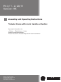
R12/17 - L120/11
Version: HK
en Assembly and Operating Instructions
Tubular drives with crank handle activation
Important information for:
• Fitters / • Electricians / • Users
Please forward accordingly!
These instructions must be kept safe for future reference.
Becker-Antriebe GmbH
Friedrich-Ebert-Straße 2-4
35764 Sinn/Germany
www.becker-antriebe.com
Assembly and Operating Instructions
Table of contents
Contents ............................................................................................................................................................................. 3
General .............................................................................................................................................................................. 3
Warranty ............................................................................................................................................................................. 4
Safety instructions ............................................................................................................................................................... 4
Intended use ....................................................................................................................................................................... 6
Installation .......................................................................................................................................................................... 6
Assembling the drive ................................................................................................................................................. 6
Assembling the drive adapter with drive adapter safety catch ........................................................................................ 7
Assembling the drive adapter with screw connection .................................................................................................... 7
Securing the drive against axial displacement .............................................................................................................. 7
Fixing the drive adapter to the barrel dia. 45 and dia. 58 ................................................................................................ 7
Mounting the drive in the tube .................................................................................................................................... 8
Setting the limit positions ..................................................................................................................................................... 9
Using the crank handle ...................................................................................................................................................... 10
Information for the electrician ............................................................................................................................................. 10
Disposal ........................................................................................................................................................................... 10
Technical data dia. 45 ........................................................................................................................................................ 11
Technical data dia. 58 ........................................................................................................................................................ 11
What to do if...? ................................................................................................................................................................. 12
Sample wiring diagrams ..................................................................................................................................................... 13
Declaration of conformity ................................................................................................................................................... 15
2
Contents
General
These tubular drives are high-quality products with the following features:
▪ For use with roller shutters
▪ For use with sunblinds
▪ For use with doors
▪ Convenient manual control in the event of power failure
▪ Easy limit switch setting on the drive
▪ Compatible with all of the drive manufacturer's control units for roller shutters and sunblinds.
Please observe these Assembly and Operating Instructions when installing and setting the equipment.
Explanation of nomenclature
Tubular drives:
Example: R12/17C PROF+
R
Type
12
/
Nm
17
min-1
C
C-Plug =
plug-in connecting cable
PROF+
Limit switch version
Types:
P = pico tube dia. 35 mm
R = regular tube dia. 45 mm
L = large tube dia. 58 mm
Limit switching versions:
M = mechanical limit switch
HK = mechanical limit switch with crank handle
G = DC drives with mechanical limit switch
GHK = DC drives with mechanical limit switch and crank handle
Electronic limit switching:
R= roller shutters
S = sun protection
F = with integrated radio receiver
P = with point-to-point switching
E = reversing in the limit position
O = with sensitive obstacle detection
SMI = Standard Motor Interface
+ (with R) = with automatic detection of anti-lifting devices
+ (with S) = higher closing force for cassette awnings
Software versions
A0…z9
Explanation of pictograms
Caution
Denotes a potentially hazardous situation. If this is not avoided, injuries may result.
Attention
Denotes a potentially hazardous situation. If this is not avoided, the product or some‐
thing in its vicinity may be damaged.
Note
Denotes user tips and other useful information.
3
Assembly and Operating Instructions
Warranty
Structural modifications and incorrect installation which are not in accordance with these and our other instructions can result in
serious injuries, e.g., crushing of limbs. Therefore, structural modifications may only be carried out with our prior approval and
strictly in accordance with our instructions, particularly the information contained in these Assembly and Operating Instructions.
Any further processing of the products which does not comply with their intended use is not permitted.
The end product manufacturer and fitter have to ensure that all the relevant current statutory, official and, in particular, EMC regu‐
lations are adhered to during utilisation of our products, especially with regard to end product manufacture, installation and cus‐
tomer advice.
Safety instructions
The following safety instructions and warnings are intended to avert hazards and to prevent property damage and personal injury.
Please keep these instructions in a safe place.
Caution
Important safety instructions for the user.
Failure to observe these instructions can lead to serious injuries.
▪ All work, including maintenance and cleaning, on electrical installations as well as other system parts must
always be performed by authorised specialists, in particular qualified electricians.
▪ Do not allow children to play with control units.
▪ Systems have to be checked regularly by authorised specialists for wear and damage.
▪ Always put damaged systems out of operation immediately until they are repaired by an authorised special‐
ist.
▪ Do not operate equipment if people or objects are within the danger zone.
▪ Observe the danger zone of the equipment during operation.
▪ Stop and disconnect the equipment from the mains power supply when maintenance and cleaning is being
performed either on the system itself or in the immediate vicinity of it.
▪ Ensure that there is adequate clearance (at least 40 cm) between moving parts and adjacent objects.
▪ Crushing or shearing points must be avoided or protected.
4
Caution
Important safety instructions for installation and commissioning
Failure to observe these instructions can lead to serious injuries.
▪ Observe the safety instructions in EN 60335-2-97. Please note that this list of safety instructions is not ex‐
haustive, since it would be impossible for the standard to include all sources of danger. For example, the
design of the operated product, the way the drive works in the situation it is installed in or even the way the
end product is mounted in the end user’s place of use cannot be taken into consideration by the drive man‐
ufacturer.
If any questions or uncertainties regarding the safety instructions contained in the standard arise, please
contact the manufacturer of the part or end product in question.
▪ All work, including maintenance and cleaning, on electrical installations as well as other system parts must
always be performed by authorised specialists, in particular qualified electricians.
▪ When electrical or electronic equipment and units are operated, certain components, e.g., the power sup‐
ply unit, are live. Physical injuries or damage to property can result in the event of unauthorised interven‐
tions or failure to heed warnings.
▪ Be careful when touching the tubular drive, as it heats up during operation for technological reasons.
▪ All applicable standards and regulations for electrical installation must be complied with.
▪ Only use spare parts, tools and accessory devices which have been approved by the drive manufacturer.
▪ Unapproved third-party products or modifications to the system and its accessories represent a risk to your
safety and the safety of others. This means that the use of unapproved third-party products, or modifica‐
tions which have not been agreed with or approved by us, are prohibited. We do not accept liability for dam‐
ages or injury arising from such actions.
▪ Before installation, shut down all lines and control devices that are not essential for operation.
▪ Position control devices within sight of the driven product, but away from moving parts, at a height of over
1.5 m.
▪ Permanently mounted control devices must be positioned where they can be seen.
▪ Ensure that there is adequate clearance between moving parts and adjacent objects.
▪ Rated torque and duty cycle must be suitable for the requirements of the driven product.
▪ Technical data – rated torque and service life can be found on the type plate of the tubular drive.
▪ Moving parts of drives must be installed at a height of over 2.5 m above floor level or any other surface from
which access to the drive is gained.
▪ Crushing or shearing points must be avoided or protected.
▪ When installing the drive, all-pole disconnection from the mains with a contact gap of at least 3 mm per pole
must be provided (EN 60335).
▪ To ensure safe operation of the system after commissioning, the limit positions must be correctly set/
programmed in.
▪ If the drive mains connecting cable is damaged, it must be replaced with the same type of mains connecting
cable, which is available from the drive manufacturer.
▪ The drive must not be carried by the mains connecting cable.
▪ Drives with a H05VV-F connecting cable may only be used indoors.
▪ When using doors, particularly the standard EN 12453 must be observed.
▪ To connect the drive to the driven part, solely mechanical accessory components made by the drive manu‐
facturer from the current product catalogue may be used. The components must be installed in accordance
with the manufacturer's instructions.
▪ All latching connections and fastening screws on the brackets must be checked to ensure that they are se‐
cure.
▪ If the drive is used for shading solutions in a specially marked area (e.g. escape routes, hazard zones, safe‐
ty areas), compliance with all applicable regulations and standards must be ensured.
5
Assembly and Operating Instructions
Intended use
The type of tubular drive described in these instructions is intended solely for the operation of roller shutters, roller doors and sun
protection systems. The crank handle is intended to be used for convenient manual operation only in the event of a power fail‐
ure. Continuous operation or use of tools (e.g. drilling machines for activation of the crank handle) is prohibited as, after a certain
amount of time, this leads to loss of manual function and with it the tubular drive.
The tubular drive must not be used in potentially explosive areas.
The mains connecting cable is not suitable for transporting the drive. Always carry the drive by the housing tube.
Other applications, uses and modifications are not permitted in order to protect the safety of the users and others, since these
actions can impair the system’s safety and carry the risk of personal injury and property damage. The drive manufacturer does not
accept liability for damages or injury arising from such actions.
Always observe the information in these instructions when operating or repairing the system. The drive manufacturer does not ac‐
cept liability for damages or injury resulting from improper usage.
Installation
Assembling the drive
Attention
To connect the drive to the driven part, solely mechanical accessory components made by the drive manufac‐
turer from the current product catalogue may be used.
Prior to mounting, the fitter must ensure that the masonry and the system being motorised are sufficiently robust (drive torque plus
weight of the shading solution).
Caution
Electrical connections may only be carried out by a qualified electrician. Prior to assembly, the power supply
must be disconnected and secured. Please give the enclosed connection information to the responsible elec‐
trical contractor.
Calculate the space required at the side (M) by measuring the drive head and wall
bracket. The clear dimension of the box (X) minus the space required at the side (M)
and idler (G) gives the length (L) of the barrel: L=X-M-G.
The space required at the side (M) varies depending on the combination of drive and
wall bracket.
Attention
The fastening elements (wall bracket) must be aligned and fixed so that tensions cannot occur when screwing
the crank handle housing.
Then mount the wall bracket and idler. Ensure that the barrel is aligned at right angles to the wall and that sufficient axial play is
allowed for the mounted system.
Attention
When using anti-lifting devices, closed brackets must be fitted. The tubular drive presses the closed curtain
down to make it difficult for people to reach under it or raise it. Only use curtains made of sufficiently strong
material, such as aluminium, steel or wood. To prevent damage to the curtain it must run in guide tracks from
top to bottom.
6
Assembling the drive adapter with drive adapter safety catch
Put the drive adapter (1) onto the drive shaft of the tubular drive. You can see where
to insert the safety catch (2) from its shape. When inserting the drive adapter safety
catch (2) into the hole (4), make sure that the locking lug (3) engages. You will hear a
click. Check that the safety catch is securely in position by pulling on the drive adapt‐
er (1).
Assembling the drive adapter with screw connection
Put the drive adapter (1) onto the drive shaft of the tubular drive. For the assembly,
use an M6 x 12 screw (3) with appropriate washer (2) and suitable screw retainer.
Threaded hole (4)
Securing the drive against axial displacement
In order to secure the drive against axial displacement, we recommend screwing the
drive adapter to the tube.
-10 mm
Attention
When drilling into the barrel, never drill near the tubular drive!
Fixing the drive adapter to the barrel dia. 45 and dia. 58
Size of drive
[mm]
Diameter of barrel
[mm]
Torque
max. [Nm]
Fastening screws
for drive adapter (4 pc.)
dia. 45
60 - 70 mm
plastic or
diecast drive adapter
40
self-tapping screw
dia. 4.8 x 9.5 mm
dia. 58
63 - 120 mm
diecast drive adapter
120
self-tapping screw
dia. 6.3 x 13 mm
dia. 58
85 - 133 mm
aluminium drive adapter
120
countersunk screw
M8 x 16 mm
We also recommend screwing the idler to the barrel.
7
Assembly and Operating Instructions
Attention
Do not hammer or drop the tubular drive into the barrel! The curtain can only be secured using springs or antilifting devices.
Mounting the drive in the tube
For profile tubes:
In the case of some drive adapters, tolerances of the groove widths in different bar‐
rels can be offset by rotating the drive adapter into a different groove recess. These
groove recesses have different sizes and allow the drive to fit exactly.
For round tubes:
First notch the tube on the motor side, so the lug of the thrust ring can also be pushed
into the tube. There must be no play between the lug of the thrust ring and the tube.
Assemble the tubular drive with the relevant thrust ring (1) and drive adapter (2). In‐
sert the tubular drive with the pre-assembled thrust ring and drive adapter into the
tube to achieve a form fit. Ensure that the thrust ring and drive adapter are secure in
the tube.
Mount the assembled unit comprising barrel, tubular drive and idler on the box as fol‐
lows.
1.First insert the bearing pin into the idler (1.).
2.Then, mount the crank handle housing onto the respective fastening element using
at least 2 M6 screws (2.).
3.Now secure the idler.
Note
When using springs/anti-lifting devices, we recommend you use at least three; for longer tubes, use three
springs/anti-lifting devices per meter of barrel.
Lay the connecting cable
Lay the connecting cable up to the tubular drive, and fix The connecting cable and
any antennae must not project into the winding chamber. Cover any sharp edges.
8
Setting the limit positions
Setting tool
The setting tool (Item no. 4933 300 019 0) can be used to set the limit positions.
Upper limit position
Lower limit position
Lower limit position
Upper limit position
Lower limit position
Upper limit position
Upper limit position
Lower limit position
Setting the lower limit position
1.Before the shading solution is fixed to the barrel, let the drive run DOWN until it switches off automatically.
2.By adjusting the lower limit position, position the barrel to make it easy to fix the shading solution to the barrel.
Setting the upper limit position
Activate the UP switch. The drive rolls up the shading solution. Extend or reduce the range of travel by turning the corresponding
set screw.
Note
Note on roller shutter use
To make allowances for any changes in the length of the roller shutter, do not mount mechanical stops. Make
sure that the individual laths cannot shift sideways.
During commissioning and subsequent use, ensure that the roller shutter curtain runs UP and DOWN smoothly
and easily.
Test for proper functioning
As a final check, run the shading solution to the limit positions in both directions again.
Attention
The tubular drives are designed for short-time operation (S2/KB 4 min). A fitted thermal protection switch pre‐
vents overheating of the tubular drive. During commissioning (long drop distance or long running time), the
thermoswitch may trigger. The drive will switch off. After a short cooling-down period, the system is ready for
operation again.
The drive does not achieve its full duty cycle until it has cooled to ambient temperature. Avoid a situation
where the thermal protection switch cuts in repeatedly.
9
Assembly and Operating Instructions
Using the crank handle
Note
For problem-free assembly, use mechanical and electrical accessories made by the drive manufacturer which
have been tested and which are suitable for use with these drives.
For 7 mm hexagonal tube
and 8 mm square tube
The crank handle is to be used only in the event of a power failure. It must be ensured
that the limit positions are not overrun.
Crank handle for closed models
The crank handle for closed models can be used with roller shutters and roller doors,
either with or without a roll-up system. The square bar is fixed to the shutter box.
Here, it is important to ensure that the bar is mounted parallel to the guide in the
crank handle housing.
Crank handle for open models
These crank handles can be used with awnings, as well as with roller shutters and
roller doors without roll-up systems. Insert the square bar into the guide in the crank
handle housing and secure axially using a retaining washer or two set screws.
Information for the electrician
The tubular drives with mechanical limit switching must not be connected in parallel. The drive manufacturer offers a range of suit‐
able controls for the simultaneous control of several drives.
Use external conductor L1 to control the up and down direction. Other devices or consumers (lamps, relays, etc.) must not be
directly connected to the drive connecting cables. For this purpose, the drives and additional devices must be decoupled by relay
controls.
When installing the drive, all-pole disconnection from the mains with a contact gap of at least 3 mm per pole must be provided (EN
60335).
Attention
Only use mechanically or electrically locked switching elements with a marked zero position! This also applies
when drives with electronic and mechanical limit switching are used in the same system. The changeover time
for switching the running direction must be at least 0.5 s. The switch and control must not execute simultane‐
ous UP and DOWN commands. Protect the electrical connections from damp.
Once you have finished wiring everything to the control, ALWAYS check the right direction assignment of the
drive to the control buttons UP and DOWN, EXTEND and RETRACT.
If the drive is to be operated with devices which contain sources of interference, the electrician must ensure
suitable interference suppression for the relevant devices.
Disposal
This product is made of various materials which must be disposed of properly. Find out about the applicable regulations on recy‐
cling or disposal for this product in your country.
The packaging material must be disposed of properly.
10
Technical data dia. 45
Type
R12/17
HK
R15/17
HK
R20/17
HK
R25/17
HK
Rated torque (Nm)
12
15
20
25
Output speed (rpm)
17
17
17
17
Limit switch range
38 revolutions
Supply voltage
230 V AC / 50 Hz
Connected load (W)
110
140
160
175
Rated current consumption (A)
0.50
0.65
0.75
0.80
Mode
S2 4 min
Degree of protection
IP 44
Min. tube inside diameter (mm)
47
Type
R30/17
HK
R40/17
HK
R50/11
HK
Rated torque (Nm)
30
40
50
Output speed (rpm)
17
17
11
Limit switch range
38 revolutions
Supply voltage
230 V AC / 50 Hz
Connected load (W)
205
260
240
Rated current consumption (A)
0.90
1.15
1.10
Mode
S2 4 min
Degree of protection
IP 44
Min. tube inside diameter (mm)
47
Technical data dia. 58
Type
L44/14
HK
L50/11
HK*
L50/17
HK
L60/11
HK
L60/17
HK*
Rated torque (Nm)
44
50
50
60
60
Output speed (rpm)
14
11
17
11
17
Limit switch range
38 revolutions
Supply voltage
230 V AC / 50 Hz
Connected load (W)
255
235
315
265
380
Rated current consumption (A)
1.20
1.05
1.40
1.20
1.75
Mode
Degree of protection
Min. tube inside diameter (mm)
S2 4 min
IP 44
60
11
Assembly and Operating Instructions
Type
L70/17
HK
L80/11
HK
L80/17
HK*
L120/11
HK
Rated torque (Nm)
70
80
80
120
Output speed (rpm)
17
11
17
11
Limit switch range
38 revolutions
Supply voltage
230 V AC / 50 Hz
Connected load (W)
430
310
470
435
Rated current consumption (A)
1.90
1.40
2.10
1.90
Mode
S2 4 min
Degree of protection
IP 44
Min. tube inside diameter (mm)
60
*) This tubular drive is not yet available.
What to do if...?
Problem
Cause
Remedy
The roller shutter curtain is raised un‐
evenly or not at all.
1.One or more attachments have broken
off.
2.Lath has broken off.
Repair system; then reset the limit posi‐
tions.
Tubular drive stops arbitrarily; cannot be
restarted in the same direction.
Roller shutter curtain keeps sticking; too
much friction.
Repair system
Tubular drive does not run in the right di‐
rection.
Electrical connection faulty.
Check the electrical connection.
12
Sample wiring diagrams
green/yellow
blue
brown
black
Operation with single switch
230 V
PE
N
L1
Single switch
13
Assembly and Operating Instructions
Central, group and individual control using Centronic UnitControl UC42
Mains 230 V / 50 Hz
Control unit
Central
Central cable
(connection to further control units)
230 V / 50 Hz
Group
230 V / 50 Hz
Individual
230 V / 50 Hz
230 V / 50 Hz
Electronics
Individual
14
Declaration of conformity
15
2010 300 231 0d
28/02/2012