1
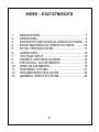
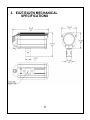
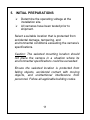
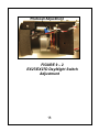
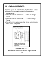
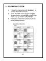
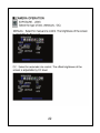
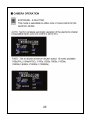
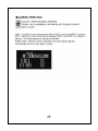
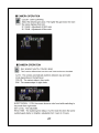
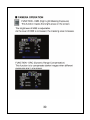
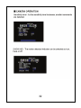
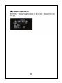
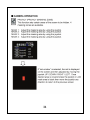
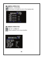
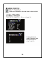
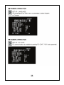
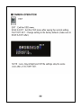
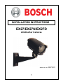
INSTALLATION INSTRUCTIONS EX27/EX27N/EX27D All-Weather Cameras MAN-27/27N/27D-01 1 IMPORTANT SAFETY INSTRUCTIONS 1. Read these instructions. 2. Keep this instruction. 3. Heed all warnings. 4. Follow all instructions. 5. Do not use this apparatus near water. 6. Clean only with dry cloth. 7. Do not block any ventilation openings. Install in accordance with manufacturer instructions. 8. Do not install near any heat sources such as radiators, heat registers, stoves or other apparatus (including amplifiers) that produce heat. 9. Do not defeat the safety purpose of the polarized or grounding-type plug. A polarized plug has two blades with one wider than the other. A grounding type plug has two blades and a third grounding prong. The wide blade or the third prong is provided for your safety. If the provided plug does not fit into your outlet, consult an electrician for replacement of the obsolete outlet. 2 10. Protect the power cord from being walked on or pinched particularly at plugs, convenience receptacles, and the power where they exit from the apparatus. 11. Only use attachments/accessories specified by the manufacturer. 12. Use only with the cart, stand, tripod, bracket, or table specified by the manufacturer, or sold with the apparatus. When a cart is used, use caution when moving the cart/apparatus combination to avoid injury from tip-over. 13. Unplug this apparatus during lightning storms or when unused for long periods of time. 14. Refer all servicing to qualified service personnel. Servicing is required when the apparatus has been damaged in a way, such as power-supply cord or plug is damaged, liquid has been spilled or objects have fallen into the apparatus, the apparatus has been exposed to rain or moisture, does not operate normally, or has been dropped. 3 IMPORTANT For best results, please read this Instruction Booklet prior to installing the EX27 camera. EU Directives covered by this declaration: 72/9/EC Low Voltage Directives 89/336/EEC Electromagnetic Compatibility Directive This installation should be made by a qualified service person and conform to all local codes. Bosch Security Systems will not be responsible for injuries or damages resulting from the improper installation or use of any camera sold by Bosch Security Systems, their agents, distributors or dealers. 4 NOTE: This equipment has been tested and found to comply with the limits for a digital device, pursuant to part 15 of the FCC rules. These limits are designed to provide reasonable protection against harmful interference in a residential installation. As part of its’ normal operation this device can generate radio frequency energy and if not installed and used in accordance with the installation manual may cause interference to radio communications. However, there is no guarantee that interference will not occur on a particular installation. If the device does cause interference to radio or television reception the user is encouraged to try to correct the interference by one or more of the following measures: 1) Fit Ferrite beads on all cable to and from the power supply box, within the box walls. 2) Route the composite cable between the camera and the power supply in steel conduit piping over the entire run of the cable up to and including connection to a deep conduit base fitted under the camera and a conduit fitting adaptor in the wall of the PSU box. 3) Contact a Bosch Service Center for further advice. 5 INDEX – EX27/27N/EX27D 1. 2. 3. 4. 5. 6. 7. 8. 9. 10. 11. 12. 13. DESCRIPTION....................................................... 7 UNPACKING .......................................................... 8 EX27/EX27N MECHANICAL SPECIFICATIONS ... 9 EX27D MECHANICAL SPECIFICATIONS........... 10 INITIAL PREPARATIONS .................................... 11 GUIDELINES........................................................ 12 VOLTAGE INPUT................................................. 13 CAMERA AND LENS ACCESS ........................... 14 PHOTOCELL ADJUSTMENTS ............................ 17 LENS ADJUSTMENTS......................................... 19 OSD MENU SYSTEM .......................................... 21 TROUBLESHOOTING GUIDE ............................. 40 GENERAL SPECIFICATIONS ............................. 43 6 1. DESCRIPTION The EX27 camera is an all-weather system that includes all of the best features of a “plug and play” camera without compromise to CCD optics and lens quality. Full size vari-focal auto-iris lenses are integrated as standard equipment for simplified installations. High resolution extended day/night CCDs ensure that a picture is received under extreme outdoor lighting conditions. The EX27 is rugged, compact, power protected, weather sealed, easily installed and designed for use in industrial applications. A voltage regulator circuit automatically allows for 12VDC or 24VAC operation without any wiring changes. Its wider voltage range also provides protection from voltage surge, transient spikes, and reverse voltage. The EX27 is available in several models to meet individual requirements or specific needs. 7 2. UNPACKING Care should be taken when unpacking. Check the parts list and confirm all items have been located. Inspect the equipment thoroughly to ensure nothing was damaged in transit. Contact a Bosch Service Center if a problem is noted, see the rear page of this booklet for contact numbers. PARTS LIST (items supplied with unit) - EX27/EX27N/EX27D camera assembly - Installation Instructions - Universal type pan/tilt mounting bracket with ¼ - 20 captive nut -3mm Allen key ITEMS REQUIRED FOR INSTALLATION (not supplied with unit) - Hardware for camera mounting (bolts, etc.) - Mounting tools and wrenches - Optional mounting brackets (contact Bosch for details and prices) 8 3. EX27/EX27N MECHANICAL SPECIFICATIONS 9 4. EX27D MECHANICAL SPECIFICATIONS 10 5. INITIAL PREPARATIONS Determine the operating voltage at the installation site. All cameras have been tested prior to shipment. Select a suitable location that is protected from accidental damage, tampering, and environmental conditions exceeding the camera’s specifications. Caution: The selected mounting location should not place the camera in a situation where its environmental specifications could be exceeded. Ensure the selected location is protected from falling objects, accidental contact with moving objects, and unintentional interference from personnel. Follow all applicable building codes. 11 6. GUIDELINES The following installation guidelines must be followed: Locate the camera such that it cannot be easily interfered with, either intentionally or accidentally. Select a mounting surface capable of supporting the combined weight of the camera and mounting hardware under all expected conditions of vibration and temperature. Secure all cabling. Installations on drywall must use a ¼” bolt and drywall butterfly type anchor or superior connection. 12 7. VOLTAGE INPUT The camera unit is pre-connected with an electrically isolated power board for 24VAC or 12VDC operation with no wiring change or wiring polarity. See figure 7-1 for wiring details. Note: Input voltage is 10.5VDC to 40VDC for DC input. The AC input range is 12VAC to 28VAC. Power IN from supply Power OUT to camera FIGURE 7 – 1 12VDC or 24VAC Electrically Isolated Board 13 8. CAMERA AND LENS ACCESS The following steps show the installer how to access the camera board and the camera lens. Step 2.1 - Remove the four cap screws with a 3mm Allen key. See Figure 8-1 on page 15. Step 2.2 - Carefully slide out the rear housing from the main enclosure. Make sure the gasket remains with the rear section. See Figure 8-2 on page 16. Step 2.3 - Make any necessary camera or lens adjustments as described in Section 9, 10 or 11. Step 2.4 - Carefully slide the rear section into the main enclosure and tighten the cap screws. 14 Cap screw FIGURE 8 – 1 Rear Housing Removal 15 FIGURE 8 – 2 Camera and Lens Access 16 9. PHOTOCELL ADJUSTMENTS The photocell settings are optimally set from the factory; only adjust these settings if experiencing undesired day/night switching operation. To increase the night switching sensitivity turn the dial clockwise, to increase the day switching sensitivity turn the dial counter-clockwise. For EX27N versions refer to figure 9-1. For EX27 and EX27D refer to figure 9-2. Power to LED Array Photocell Adjustment 12V Enable Power Input FIGURE 9 – 1 EX27N LED Array Power Board 17 Photocell Adjustment FIGURE 9 – 2 EX27/EX27D Day/Night Switch Adjustment 18 10. LENS ADJUSTMENTS Refer to figure 10-1 and follow the directions below: Loosen the lens set screws for focus/zoom adjustments. The adjustment marked T ←→ W is for image zoom. The adjustment marked N ←→ ∞ is for image focus. Re-tighten the setscrews after focus adjustments have been completed. FIGURE 10 – 1 EX27 Vari-focal Lens Focus Adjustment 19 Use a Neutral Density filter or an Infra-Red Pass filter to cover the lens during focusing to simulate low light conditions on scene for correct 24-hour focusing. For varifocal lenses, the camera should be focused with the lens iris fully opened to simulate the worst possible depth of field. Using a Neutral Density filter or Infra-Red Pass filter will ensure the iris is fully open for correct setup and adjustment. Note that statement above is applicable only for Day/Night or IR version cameras. 20 11. OSD MENU SYSTEM 1. Follow the instructions in Section 8 to access the OSD controls. 2. Enter the OSD menu by pressing the joystick button; to navigate through the menu use up, down, left and right. 3. Follow the instructions below to make camera adjustments. 21 22 23 24 25 26 27 28 29 30 31 32 33 34 35 36 37 38 39 12. TROUBLESHOOTING GUIDE PROBLEM No Video POSSIBLE CAUSE 1. Power Supply: -Connections…. -Voltage Range... LIKELY SOLUTION Check input power connections at the cable leads. Check for loose wires. If connected to DC, check voltage input range of 10.5 - 40 V. If connected to AC, check input voltage range of 12 – 28 V. Measure the voltage at the Input terminal block. 40 No Video (cont’d.) 2. Video Connections Determine if wiring polarity at “Video Connector” terminal block is correct. Check BNC connector. If still no video, connect the camera directly to the monitor. Check the video signal. If okay, the problem is with the interconnections. If still no video, contact a Bosch Service Center. See rear page of this manual for contact information. __________ Poor Picture Quality ________________ Snowy Image Poor Video Signal 41 _________________ Ensure video cable is correctly matched and terminated with 75 ohms at each end. Make sure video cables are similar types. Poor Picture Quality Snowy Image (cont’d.) Noisy Power Supply Check connections. Relocate or replace power supply. Horizontal Scan Lines, Rolling Up or Down Ground Looping on video cable Check the coax cable shield is not touching ground, e.g. at couplings. An electrically isolated circuit board or isolation transformer may be required. 24V ac operation Line Lock adjustment required. Low voltage Check voltage at input power cable. Must be >10.5V dc or >12V ac. Negative, scrambled, or faded image 42 13. GENERAL SPECIFICATIONS Input Voltage: 10.5-40 VDC 12-28 VAC (50/60Hz), 4.5W Enclosure (housing): Aluminum casting and extrusion (sealed to IP66 / NEMA4) Viewing Window: Polycarbonate Weight: 1.4kg ( 3.1lbs. ) Subject to Change Without Notice. 43 Notes: 44 Notes: 45 Notes: 46 Notes: 47 Americas Bosch Security Systems, Inc. 850 Greenfield Road Lancaster, Pennsylvania 17601 USA Telephone: + 1 888-289-0096 Fax: + 1 585-223-9180 [email protected] www.boschsecurity.us Europe, Middle East, Africa Bosch Security Systems B.V. P.O. Box 80002 5600 JB Eindhoven, Netherlands Phone: + 31 40 2577 284 Fax: + 31 40 2577 330 [email protected] www.boschsecurity.com Asia Pacific Bosch Security Systems Pte Ltd. 11 Bishan Street 21, Singapore, 573943 Phone: +65 6319 3450 Fax: +65 6319 3499 [email protected] www.boschsecurity.com © Bosch Security Systems Inc. 2010; Data subject to change with out notice 48