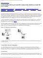
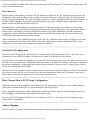
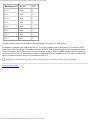
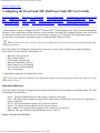
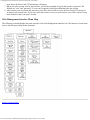
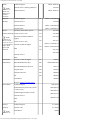
1
Contents: Dell PowerVault 35F User's Guide
Dell™ PowerVault™ 35F User's Guide
Safety Instructions
Introducing the PowerVault™ 35F
Installing the PowerVault 35F
Understanding the PowerVault 35F Configuration
Configuring the PowerVault 35F
Troubleshooting
Getting Help
Ethernet Pin Assignments
Fibre Channel Interface and Commands
SCSI Interface and Commands
Addressing, Structures and Operation
Management Information Base (MIB)
Regulatory Notices
Warranties, Return Policy, and Year 2000 Compliance
Sample Configuration Examples
Glossary
Information in this document is subject to change without notice.
© 1999 Dell Computer Corporation. All rights reserved.
Reproduction in any manner whatsoever without the written permission of Dell Computer Corporation is
strictly forbidden.
Trademarks used in this text: Dell, the DELL logo, PowerVault , and DellWare are trademarks of Dell
Computer Corporation; UNIX is a registered trademark of UNIX System Laboratories, Inc., a wholly owned
subsidiary of Novell, Inc.; Microsoft and Windows NT are registered trademarks of Microsoft Corporation.
Other trademarks and trade names may be used in this document to refer to either the entities claiming the
marks and names or their products. Dell Computer Corporation disclaims any proprietary interest in
trademarks and trade names other than its own.
file:///C|/Users/rishi_sood/Desktop/35F/ug/index.htm[3/21/2013 11:16:14 AM]
Contents: Dell PowerVault 35F User's Guide
Initial release: February 1999
file:///C|/Users/rishi_sood/Desktop/35F/ug/index.htm[3/21/2013 11:16:14 AM]
Safety Instructions: Dell PowerVault 35F User's Guide
Back to Contents Page
Safety Instructions: Dell PowerVault 35F User's Guide
Alert Messages | Laser Safety | Product Information
Alert Messages
WARNING: A WARNING denotes a hazard that can cause personal injury.
CAUTION: A CAUTION denotes a hazard that can cause hardware or software damage.
NOTE: A NOTE denotes information that might be of special interest. A note can point out exceptions to
rules or procedures.
Grounding
This product is a Safety Class 1 product and has a protective earthing terminal. There must be an uninterruptible safety
earth ground from the main power source to the product’s input wiring terminals, power cord, or supplied power cord
set. Whenever it is likely that the protection has been impaired, disconnect the power cord until the ground has been
restored.
Servicing
Any servicing, adjustment, maintenance, or repair must be performed only by authorized service-trained personnel.
There are no operator serviceable parts in this product.
Warranty
If you have any questions about the warranty of this product, contact a Dell sales representative.
Laser Safety
Certification and Classification Information
This product uses Gigabit Interface Converters (GBIC) to interface with Fibre Channel links. Optical GBICs shipped
with this product contain internal lasers. In the USA, all optical GBICs shipped with this unit are certified as Class 1
laser products and conform to the requirements contained in the Department of Health and Human Services (DHHS)
regulation 21 CFR Subchapter J.
Outside the USA, all GBICs are certified as Class 1 laser components that conform to the requirements contained in
the International Electrotechnical Commission (IEC) standard 825 (1994) and Amendment 1 (1990) along with the
CENELEC (European Committee for Electrotechnical Standardization) European Normalization standard EN 60825
(1992).
If other then the shipped optical GBICs are used with this product then the user is required to insure that the optical
file:///C|/Users/rishi_sood/Desktop/35F/ug/safety.htm[3/21/2013 11:16:17 AM]
Safety Instructions: Dell PowerVault 35F User's Guide
GBIC being used meets all of the above requirements. If the GBIC is not certified then this product’s laser safety
certification becomes null-and-void.
Certifications include one or more of the following:
Recognized Component by Underwriters Laboratories
Certified by the Canadian Standard Association
Certified by VDE (Germany) and/or Certified by Statens Provningsanstalt (SP) in Sweden
The following shows the Class 1 information label specified in IEC 825 and CENELEC HD 482 51. This label is
attached to this product.
Class 1 Laser Product
Laser Klasse 1
Luckan 1 Laserlaite
The following information provides the typical operational parameters for the Optical Laser GBIC included with the
PowerVault 35F.
Laser Information
Parameter
Shortwave
Longwave
Nomenclature
100-M5-SN-I 100-SM-LC-L
Spectral Centre
Wavelength
770-850nm
1300nm
Operating Range
2m-500m
2m-10km
Launch Power Max
1.3 dBm
-3 dBm
Launch Power Min
-7 dBm
Receive Power Min
-13 dBm
-20 dBm
Receive Power Max
1.3 dBm
-3 dBm
Extinction Ratio
6 dB
9 dB
TX Deterministic Jitter
20 ps
20 ps
Fibre Diameter
50um
9um
Class
Multimode
Single-mode
Nominal Bit Rate
1062.5
Mbaud
1062.5 Mbaud
OFC
none
none
NOTE: Class 1 Laser Products are not considered hazardous.
Product Information
Each Fibre Channel communications port consists of a transmitter and receiver optical subassembly. The transmitter
subassembly contains internally a semiconductor laser diode in the wavelength of 780 or 1300 nanometers.
file:///C|/Users/rishi_sood/Desktop/35F/ug/safety.htm[3/21/2013 11:16:17 AM]
Safety Instructions: Dell PowerVault 35F User's Guide
WARNING: There are no user maintenance or service operations or adjustments to be performed on any
of the GBIC modules.
Usage Restrictions
Failure to comply with these usage restrictions may result in incorrect operation of the system and points of access
may emit laser radiation above the Class 1 limits established by the IEC and U.S. DHHS.
Back to Contents Page
file:///C|/Users/rishi_sood/Desktop/35F/ug/safety.htm[3/21/2013 11:16:17 AM]
Introducing the PowerVault 35F: Dell PowerVault 35F User's Guide
Back to Contents Page
Introducing the PowerVault™ 35F: Dell PowerVault 35F User's Guide
Features | Specifications | PowerVault 35F Benefits | How the PowerVault 35F Works | Operating as Both a
SCSI and Fibre Channel Device | Processing SCSI Information
The Dell™ PowerVault™ 35F is a Fibre Channel-to-SCSI bridge. The PowerVault 35F provides connectivity between
a Fibre Channel environment and two Fast/Wide/Ultra SCSI buses.
Supported devices include:
Initiator Devices – Fibre Channel and SCSI hosts
Sequential Access Devices – Tape drives
Changer Devices – Tape Libraries
Figure 1. Front panel of the PowerVault 35F
Figure 2. Back panel of the PowerVault 35F
Features
Fibre Channel Features
Fibre Channel initiator and target modes
Single 1.0625 Gbps port
Fibre Channel Arbitrated Loop (FC-AL) and Switched Fabric (FC-SW) topologies
Private Loop Direct Attach (PLDA) profile compliant
Class 3 connection with SCSI-FCP protocol
GBIC Support
SCSI Bus Features
SCSI initiator and target modes
Two auto-negotiating SCSI buses (Narrow, Wide, Fast, Ultra)
Ultra Wide SCSI for data transfer up to 40 MB/s per bus
file:///C|/Users/rishi_sood/Desktop/35F/ug/intro.htm[3/21/2013 11:16:17 AM]
Introducing the PowerVault 35F: Dell PowerVault 35F User's Guide
Connection for up to 30 devices (15 per bus)
Simultaneous commands, tagged command queuing and disconnect/reconnect
Middle of bus configuration with external termination
SCSI-2 and SCSI-3 protocols
68-pin D shell, P type connectors
High-voltage Differential support
Tape and tape changer devices
SCC, Indexed and Automatic addressing modes
Configuration Features
Serial RJ-11 connector for terminal access
Ethernet RJ-45 connector for FTP, Telnet and Web browser access
Easy field-upgradable firmware
Management Features
Out-of-band Ethernet TCP/IP
SNMP with private MIB support
Specifications
Physical Specifications
Internal power supply with power switch and detachable power cord
Fibre Channel activity LED
SCSI Bus 1 activity LED
SCSI Bus 0 activity LED
Ethernet activity LED
Power LED
Fault LED
Airflow with internal fan
Desktop or optional rack mount enclosure
Physical Dimensions
Width 43.18cm (17.00 inches)
Depth 22.82cm (8.98 inches)
Height 4.31cm (1.70 inches, 1U)
Weight 3.18 kg (7 lbs)
Operating Environment
5 to 40 °C
5 to 80% Relative Humidity (non-condensing)
Non-operating Environment
-40 to +55 °C
0 to 92% Relative Humidity (non-condensing)
file:///C|/Users/rishi_sood/Desktop/35F/ug/intro.htm[3/21/2013 11:16:17 AM]
Introducing the PowerVault 35F: Dell PowerVault 35F User's Guide
Power
100 - 240 VAC, Auto Sensing
50/60 Hz, 1.0 Amps
PowerVault 35F Benefits
Point-to-Point
Single initiator to single target
Single Initiator
Single initiator to multiple targets
Multi-Initiator
Multiple initiators to single or multiple targets
Connectivity – SCSI devices may be attached to Fibre Channel storage networks to share data and increase address
space.
file:///C|/Users/rishi_sood/Desktop/35F/ug/intro.htm[3/21/2013 11:16:17 AM]
Introducing the PowerVault 35F: Dell PowerVault 35F User's Guide
Distance – SCSI cable length from hosts to devices is increased from 25m to 10,000m, facilitating remote or disaster
tolerant sites.
Performance – 100 Mbytes/sec Fibre Channel (200 Mbytes/sec bi-directional) offers increased bandwidth when
distributing data across multiple SCSI devices.
Reliability – Low error rates, robust error recovery and flow control provide an enterprise with reliable data delivery.
Scalability – Point-to-point links can be expanded to multi-initiator links supporting interconnected servers, tape
drives and tape libraries.
Flexibility – The PowerVault 35F allows Fibre Channel initiators to communicate with SCSI targets.
Consolidation – The PowerVault 35F allows multiple servers to share storage resources, including tape drives and
tape libraries.
Centralization – The PowerVault 35F enables existing storage to be moved to a central location to simplify
management and maintenance, and to improve security.
Lower TCO – Improving storage management, maintenance and security can lower Total Cost of Ownership (TCO)
for enterprise storage.
How the PowerVault 35F Works
The PowerVault 35F is a storage bridge that translates Fibre Channel Protocol (FCP) to and from two SCSI buses so
devices on these two types of media can communicate with each other. It attaches to a Fibre Channel host, and
transfers the command, data, and status information to SCSI targets. The host passes packets to SCSI targets as if the
PowerVault 35F were just another device along the path.
The PowerVault 35F provides connections for two SCSI buses into a Fibre Channel environment. It takes advantage of
Fibre Channel’s ability to encapsulate SCSI protocol packets to allow a host with a Fibre Channel adapter to access
SCSI peripheral devices transparently over a Fibre Channel connection.
Figure 3. Fibre Channel-to-SCSI configuration
Figure 3 shows a Fibre Channel-to-SCSI configuration. Through the PowerVault 35F bridge, any host on the Fibre
Channel loop can access the tape drive and library on each SCSI bus.
file:///C|/Users/rishi_sood/Desktop/35F/ug/intro.htm[3/21/2013 11:16:17 AM]
Introducing the PowerVault 35F: Dell PowerVault 35F User's Guide
Operating as Both a SCSI and Fibre Channel Device
The bridge is both a SCSI and Fibre Channel device operating on a SCSI bus and Fibre Channel network
simultaneously.
The SCSI Side
On a SCSI bus, the PowerVault 35F acts as a SCSI initiator passing requests from hosts on the Fibre Channel network
to target devices on the SCSI bus. Each PowerVault 35F SCSI bus uses a single SCSI ID. The default ID is 7 and can
be changed when configuring the PowerVault 35F.
The Fibre Channel Side
In a Fibre Channel loop, the PowerVault 35F is identified by a single Arbitrated Loop Physical Address (AL_PA) or a
fabric assigned Source ID. Once the address is acquired, any host on the Fibre Channel loop can access the devices on
a SCSI bus transparently over a Fibre Channel connection.
Mapping Devices
To allow Fibre Channel and SCSI devices to address each other, the PowerVault 35F creates a table that maps device
identifiers between Fibre Channel and SCSI. During PowerVault 35F configuration, you can choose the mapping
method and, in certain cases, customize the device mappings. See Understanding the PowerVault 35F Configuration
for more information about address modes and their configurations.
Processing SCSI Information
The following describes how the bridge processes SCSI information:
1. A Fibre Channel host issues a command. The Fibre Channel host encapsulates the command in the Fibre
ChannelP protocol and sends the packet to the PowerVault 35F.
2. The Fibre Channel port in the PowerVault 35F receives the packet, interprets the Fibre Channel information, and
places the packet in buffer memory.
3. The PowerVault 35F’s processor interprets the information and programs a SCSI controller to process the
transaction.
4. The SCSI controller sends the command to the SCSI device (target).
Figure 4. Information processing
file:///C|/Users/rishi_sood/Desktop/35F/ug/intro.htm[3/21/2013 11:16:17 AM]
Introducing the PowerVault 35F: Dell PowerVault 35F User's Guide
5. The target interprets the command and prepares to either read or write data.
6. Data flows between the host and target through payload buffers.
7. Response information flows from the SCSI target back to the Fibre Channel host.
Back to Contents Page
file:///C|/Users/rishi_sood/Desktop/35F/ug/intro.htm[3/21/2013 11:16:17 AM]
Installing the PowerVault 35F: Dell PowerVault 35F User's Guide
Back to Contents Page
Installing the PowerVault 35F: Dell PowerVault 35F User's Guide
Location | Unpacking the Box | Interfaces and Connections | Fibre Channel Connection | GBIC Installation | Connecting the PowerVault 35F to a Fibre Channel Storage Area Network | SCSI Connection | Ethernet
Connection | Serial Port Connection | Autobaud Feature | Connecting the Power Cord
This section describes how to setup and install the Dell™ PowerVault™ 35F. This includes unpacking the PowerVault
35F for the first time, factors to consider when installing the PowerVault 35F and connecting to different types of
devices. Read this section carefully and completely before working with the PowerVault 35F.
A number of factors need to be considered in planning the installation of the PowerVault 35F. These factors include
the location of the unit, the use of the unit, and the type of devices to which the unit will be attached.
Location
The PowerVault 35F bridge can be placed on a desktop or mounted in a standard Dell rack depending on the specific
requirements of the installation. The operating environment should meet the requirements found in Introducing the
PowerVault 35F. If you plan to use the bridge on a tabletop, attach the stick-on feet to the bottom of the bridge to
protect the surface.
NOTE: The PowerVault 35F contains a cooling fan mounted in the rear of the enclosure and intake vents on the
front of the enclosure. The rear fan vent and the front intake vents should remain clear of obstructions to ensure
proper airflow.
Unpacking the Box
1. Remove all items from the shipping container. Check each one for damage. Keep the PowerVault 35F in the
protective bag until you are ready to install it.
2. Refer to the packing slip or contents list to make sure you received all the equipment you ordered. If an item is
missing, contact your Dell sales representative immediately.
3. Select a location that ensures the front intake vents and rear fan are clear of obstructions so air flows freely
through the bridge.
4. Do not connect any devices or cables to the PowerVault 35F until the device is secured in a Dell rack or placed
securely on a flat, level surface.
Interfaces and Connections
There are four types of physical interfaces to the PowerVault 35F:
Fibre Channel
SCSI
RS-232 (Serial port)
Ethernet
The RS-232 and Ethernet ports are used primarily for PowerVault 35F configuration and management. MIB
information for each interface is discussed in Management Information Base (MIB).
file:///C|/Users/rishi_sood/Desktop/35F/ug/install.htm[3/21/2013 11:16:18 AM]
Installing the PowerVault 35F: Dell PowerVault 35F User's Guide
Figure 1. Port locations
Fibre Channel Connection
Before connecting the PowerVault 35F to other Fibre Channel devices, it is important to understand the configuration
requirements of the environment to which it will be connected. Failure to correctly configure a Fibre Channel device
may impair the operation of the storage area network to which it is attached.
Typical installations will have the PowerVault 35F connected to a switched fabric environment. In Fibre Channel
switched environments, the switch is directly attached to the PowerVault 35F.
Figure 2. Configurations with tape library
Switches may allow for individual ports to be configured for different media types. The PowerVault 35F must be
connected to a switch port with a shortwave multi-mode fiber (1.0625 Gbaud Dual SC) connector.
GBIC Installation
The PowerVault 35F ships with a Gigabaud Interface Converter (GBIC) installed. If it is not already installed, follow
the instructions below to install your GBIC in the PowerVault 35F.
WARNING: The PowerVault 35F has been qualified with a specific set of GBICs. Using a GBIC that has
not been qualified by Dell may cause the PowerVault 35F to operate improperly.
1. Remove GBIC from packaging.
2. Locate the Fibre Channel port on the back of the PowerVault 35F.
file:///C|/Users/rishi_sood/Desktop/35F/ug/install.htm[3/21/2013 11:16:18 AM]
Installing the PowerVault 35F: Dell PowerVault 35F User's Guide
Figure 3. Fibre Channel port
3. Firmly insert the GBIC into the Fibre Channel port until you feel it snap into position.
Figure 4. GBIC without rubber protector
The GBIC should be protected by a rubber cap. Keep this cap in place until you’re ready to connect the PowerVault
35F to a Fibre Channel environment.
To remove the GBIC, lift the metal latch and pull outward, or use the appropriate extraction tool.
Connecting the PowerVault 35F to a Fibre Channel Storage Area Network
Follow the directions below to connect the PowerVault 35F to a Fibre Channel SAN.
1. Locate the Fibre Channel port on the back of the PowerVault 35F.
Figure 5. Fibre Channel port
2. Remove the rubber cap from the GBIC, as shown in Figure 8, and push the metal latch down to lock it into
place.
Figure 6. Removal of GBIC cap
file:///C|/Users/rishi_sood/Desktop/35F/ug/install.htm[3/21/2013 11:16:18 AM]
Installing the PowerVault 35F: Dell PowerVault 35F User's Guide
WARNING: The PowerVault 35F has been qualified with a specific set of GBICs. Using a GBIC that
has not been qualified by Dell may cause the PowerVault 35F to operate improperly.
3. With the PowerVault 35F powered off, connect the PowerVault 35F into your Fibre Channel environment using
the appropriate cabling. The connectors on the PowerVault 35F are keyed. Be sure to insert the cable connectors
in the proper orientation.
SCSI Connection
The PowerVault 35F supports Fast/Ultra Wide SCSI. The PowerVault 35F is factory configured to support a
Differential SCSI bus. Two 68-pin D-shell connectors are located on the rear panel of the unit, allowing the unit to be
attached in the middle or at the end of a SCSI bus. If the PowerVault 35F is located at one end of the SCSI bus, an
external terminator should be installed. Two terminators are provided with the PowerVault 35F.
Differential SCSI support is indicated by this symbol on the rear of the PowerVault 35F.
NOTE: The PowerVault 35F only supports Differential SCSI cables and terminators. Single-Ended SCSI
connectors and LVD SCSI connectors are not supported.
The PowerVault 35F supplies termination power (TERMPWR) on each SCSI bus. A self-resetting fuse is used that
will reset after the fault is cleared.
To connect the PowerVault 35F to a SCSI bus:
1. Power off your SCSI devices and the PowerVault 35F.
2. Connect a SCSI cable to one of the SCSI connectors on the back of the bridge.
3. Connect the other end of the SCSI cable to the next SCSI device on the bus. It is recommended that tape devices
be evenly distributed between SCSI buses for best performance.
4. If the PowerVault 35F is at the end of the SCSI bus, place the terminator provided with the bridge on the
PowerVault 35F’s other SCSI connector on the same bus. If the bridge is not at the end of the bus, attach a
second SCSI cable to the other SCSI connector. Connect this cable to the next device on the bus.
Figure 7. PowerVault 35F SCSI connection
file:///C|/Users/rishi_sood/Desktop/35F/ug/install.htm[3/21/2013 11:16:18 AM]
Installing the PowerVault 35F: Dell PowerVault 35F User's Guide
5. Make sure each bus is terminated correctly. The devices at each end of each bus must be terminated. Typically
the lower connectors are terminated, as shown in Figure 8.
Figure 8. SCSI terminator
NOTE: Power on all SCSI devices and the PowerVault 35F before powering on the switch or any of the
devices in the Fibre Channel environment to ensure SCSI devices are detected.
6. Power on your SCSI devices and allow time to initialize.
7. After all the SCSI devices have completed their individual POSTs, power on the PowerVault 35F.
NOTE: There may be several moments before the PowerVault 35F appears to be functioning after the unit
is powered up. This is normal and does not indicate a faulty unit.
8. Power on the switch and any Fibre Channel devices last.
NOTE: See Sample Configuration Example for sample configuration examples.
Ethernet Connection
10BaseT Ethernet connectivity is used to provide enhanced management and configuration capabilities. The RJ-45
connector on the unit can be directly connected to a standard 10BaseT Ethernet network.
NOTE: The PowerVault 35F only supports a 10BaseT Ethernet network connector. 100BaseT Ethernet is not
currently supported.
Configuration is required to set the IP network address to allow for use of the configuration capabilities of this port.
Refer to Configuring the PowerVault 35F for details on setting the IP network address.
NOTE: The PowerVault 35F contains a unique Ethernet MAC address that is assigned during the manufacturing
process.
Ethernet capabilities include Telnet for configuration, FTP and TFTP for firmware upgrades, and SNMP for
configuration and management.
file:///C|/Users/rishi_sood/Desktop/35F/ug/install.htm[3/21/2013 11:16:18 AM]
Installing the PowerVault 35F: Dell PowerVault 35F User's Guide
Figure 9. PowerVault 35F Ethernet port
Serial Port Connection
The RJ11 connector on the rear panel of the PowerVault 35F provides an RS-232 connection that can be used to
configure the PowerVault 35F, monitor diagnostic status, or to update the program stored in the PowerVault 35F’s
Flash memory. A cable is provided with the unit to connect to a DB-9 serial connection. Further information on the
operations allowed via the RS-232 port is provided in Configuring the PowerVault 35F.
The RS-232 port operates with the following settings:
Baud Rate: Autobaud (9600, 19200, 38400, 57600, or 115200)
Data Bits: 8
Stop Bits: 1
Parity: None
Flow Control: None
Figure 10. PowerVault 35F Serial port
Autobaud Feature
The autobaud feature automatically configures the baud rate on the PowerVault 35F on initial connection. Once you set
the baud rate in the terminal emulation program, wait until the PowerVault 35F completes the Power On Self Test
(POST) and then the Firmware Initialization process. This can take up to 90 seconds. Then press the Enter key five or
six times and the PowerVault 35F will automatically detect the baud rate and configure the bridge.
NOTE: The baud rate is then saved in the PowerVault 35F’s configuration and will be retained through future
power cycles.
NOTE: Hitting the Enter key before the POST has completed has no effect on the autobaud feature. Wait until
both the POST and the Firmware Initialization processes have completed before hitting the ENTER key. This may take
up to 90 seconds.
The baud rate in the terminal emulation program must be set at 9600, 19200, 38400, 57600, or 115200 for the autobaud
feature to recognize it. The PowerVault 35F will not function properly at any other baud rate.
file:///C|/Users/rishi_sood/Desktop/35F/ug/install.htm[3/21/2013 11:16:18 AM]
Installing the PowerVault 35F: Dell PowerVault 35F User's Guide
Connecting the power cord
The PowerVault 35F is shipped with the appropriate power cord for use in your region or country.
To connect the power cord to the PowerVault 35F:
1. Make sure the PowerVault 35F’s power is switched off. See Fig. 11 for the location of the power switch on the
back of the bridge.
2. Connect the appropriate end of the power cord to the power connector on the back of the PowerVault 35F.
3. Plug the three-pronged end of the power cord into the power source.
Figure 11. PowerVault 35F power switch and outlet
Back to Contents Page
file:///C|/Users/rishi_sood/Desktop/35F/ug/install.htm[3/21/2013 11:16:18 AM]
Understanding the PowerVault 35F Configuration: Dell PowerVault 35F User's Guide
Back to Contents Page
Understanding the PowerVault 35F Configuration: Dell PowerVault 35F
User's Guide
General Fibre Channel Configuration | General SCSI Configuration | Fibre Channel Host to SCSI Target
Configuration | Address Mapping | Indexed Addressing | Auto Addressing | SCC Addressing | SCSI Host
to Fibre Channel Target Configuration
Of primary importance in configuring the Dell™ PowerVault™ 35F is determining the mode of operation required.
The unit can be configured to support Fibre Channel hosts communicating with SCSI targets. The default configuration
of the unit allows for Fibre Channel hosts to connect to SCSI targets. Configuration is needed in some cases to modify
the method in which this occurs, as well as to support SCSI hosts communicating with Fibre Channel targets. Other
functions and features can be configured as well, and are discussed further in this section.
A typical configuration would have a Fibre Channel host connecting either via a Fiber Channel switch, or directly to
the PowerVault 35F, with SCSI target devices attached to the PowerVault 35F. These configurations, using a tape
library and drives, are represented in Figure 1.
The factory default configuration of the unit allows such a configuration to work without further configuration in most
cases. It should, however, be recognized that more complex installations or specific application requirements may
require one or more configuration elements to be changed from the default settings.
Figure 1. Configurations with tape library
An understanding of the basic characteristics of Fibre Channel and SCSI devices is recommended before configuring
the PowerVault 35F.
General Fibre Channel Configuration
On a Fibre Channel arbitrated loop, the PowerVault 35F appears at a single Arbitrated Loop Physical Address
(AL_PA). Fibre Channel devices support two methods for obtaining an AL_PA, these being soft or hard addressing.
The PowerVault 35F can be configured to use soft addressing (default) or hard addressing with a selected value.
Soft Addressing
When acquiring a soft address, the PowerVault 35F acquires the first available loop address starting from address 0. In
this mode, the PowerVault 35F automatically obtains an available address and participates on the loop, as long as there
file:///C|/Users/rishi_sood/Desktop/35F/ug/config_1.htm[3/21/2013 11:16:19 AM]
Understanding the PowerVault 35F Configuration: Dell PowerVault 35F User's Guide
is at least one address available on the loop that is connected to the PowerVault 35F. Fibre Channel supports up to 126
devices on an arbitrated loop.
Hard Addressing
When acquiring a hard address, the PowerVault 35F attempts to acquire the AL_PA value that was specified by user
configuration. If the desired address is not available at loop initialization time, the PowerVault 35F comes up on the
loop in non-participating mode. This allows the loop to continue to operate, although the unit will not be accessible via
the Fibre Channel interface. This would occur when another device on the arbitrated loop has acquired the same
address as that configured on the PowerVault 35F.
Hard addressing is recommended for environments where it is important that the device addresses do not change.
Device address changes can affect the mapping represented by the host operating system to the application, and have
adverse effects. An example of such an environment would be a tape library installation, where the application
configuration requires fixed device identification for proper operation. Hard addressing will insure that the device
identification to the application will remain constant.
When connected to a Fibre Channel Switch, the PowerVault 35F is identified to the switch as a unique device by the
factory programmed World Wide Name (WWN). No further configuration is needed, although the WWN can be
configured to a user-defined value through the configuration interface.
General SCSI Configuration
The PowerVault 35F appears on each SCSI bus as a single initiator. The default initiator ID is 7, and can be set via
configuration to any valid SCSI address. No other devices on the SCSI bus may use this address.
The PowerVault 35F provides the capability to reset the SCSI buses during the boot cycle. This allows the devices on a
SCSI bus to be in a known state. Configuration allows this feature to be enabled or disabled. This feature is enabled in
the default configuration. Configurations using multiple devices that have long reset cycles, or are adversely affected
by bus resets, should disable this feature.
The PowerVault 35F negotiates for the maximum values for transfer rates and data width on a SCSI bus. If an attached
device does not allow the full rates, the unit will use the rates negotiated for that device. Negotiation is on a device
specific basis, so the unit can support a mix of device types on the same bus.
Fibre Channel Host to SCSI Target Configuration
This section describes the configuration of the PowerVault 35F when acting as a target to a Fibre Channel Initiator,
passing Fibre Channel Protocal (FCP) requests through to SCSI target devices.
This is configured as the default, using soft addressing on the Fibre Channel loop and auto addressing for the target
device mapping. Auto addressing is described further in this section.
The PowerVault 35F automatically detects if it is connected to an FL or F_Port, and will use the appropriate type
without further configuration.
Address Mapping
The PowerVault 35F supports three addressing methods for mapping SCSI targets to Fibre Channel Hosts:
file:///C|/Users/rishi_sood/Desktop/35F/ug/config_1.htm[3/21/2013 11:16:19 AM]
Understanding the PowerVault 35F Configuration: Dell PowerVault 35F User's Guide
Indexed Addressing – Allows you to edit and maintain a static address mapping table.
Auto Addressing – Automatically creates a new address mapping table every time the PowerVault 35F is power
cycled.
SCC Addressing – Implements the SCSI-3 Controller Commands SCSI storage array addressing to address SCSI
devices attached to the PowerVault 35F.
SCSI Targets are selected by mapping the appropriate values into the FCP LUN field, and correlating a Fibre Channel
LUN value to a SCSI Bus:Target:LUN value. The PowerVault 35F acts as a single initiator on each SCSI bus,
defaulting to ID 7. All commands passed through to a SCSI bus originate from this SCSI ID.
NOTE: The SCSI bus number corresponds to the physical SCSI ports on the back of the PowerVault 35F. For
example, SCSI bus 0 corresponds to SCSI port 0 on the rear of the PowerVault 35F. SCSI bus 1 corresponds to SCSI
port 1.
Indexed Addressing
Indexed Addressing allows for generic Fibre Channel host bus adapters to access SCSI devices attached to the
PowerVault 35F. This is done by use of a table which is indexed by sequential FCP LUN values, indicating selected
BUS:TARGET:LUN devices.
Table 1. Indexed Addressing Table
FCP LUN Value
SCSI
BUS:TARGET:LUN
0
0:0:0
1
0:1:0
2
0:2:0
3
0:3:0
4
0:4:0
5
0:5:0
6
0:6:0
0:7:0 occupied by initiator
ID
7
0:8:0
(…)
(…)
14
0:15:0
15
0:0:1
16
0:1:1
(…)
(…)
file:///C|/Users/rishi_sood/Desktop/35F/ug/config_1.htm[3/21/2013 11:16:19 AM]
Understanding the PowerVault 35F Configuration: Dell PowerVault 35F User's Guide
The Indexed Addressing table has the structure shown in Table 1. The PowerVault 35F will allow up to 80 device
entries to be mapped. The index table can be manually edited, and is then saved to FLASH memory. A configuration
menu allows for the table to be filled in order of increasing target, or LUN, as may be desired for the specific
requirements needed. An assist is also provided to perform device discovery, and fill the table in the order that devices
are discovered on a SCSI bus.
Indexed Addressing mode is recommended for environments where device configuration may change, and a fixed
mapping from the application to the target devices is required. An example of such an environment is where hot plug
devices may be used, thereby changing the order of devices on a SCSI bus.
Auto Addressing
The Auto Addressing option is similar to Indexed Addressing, but with the distinction that the table used is created
through SCSI device discovery upon power up or reset, and not otherwise retained. As the unit performs device
discovery on a SCSI bus, the Index table is filled with adjacent FCP LUNs referencing each subsequent SCSI device.
The host system will then detect every attached device without voids, allowing full device discovery to the host. This
allows easy configuration in environments where device ordering is not important, and hot plugging of SCSI devices
will not occur. Configuration allows for discovery to be performed in order of target or LUN, as desired for the
specific environment.
Auto Addressing, target mode is configured as the default mode of thePowerVault 35F.
SCC Addressing
The PowerVault 35F implements the SCSI-3 Controller Commands (SCC) (X3T10 Project 1047D Revision 6b 01July-96) ) SCSI storage array addressing to address SCSI devices attached to the PowerVault 35F. The Access Method
used is the SCC Logical Unit Addressing method.
In SCC Addressing mode, the PowerVault 35F will respond to FCP commands, as in a SCC controller device. A
subset of the SCC behavior is implemented. LUN mappings corresponding to the SCC Peripheral Device Addressing
are interpreted as controller commands, and are acted on by the PowerVault 35F directly. LUN mappings using SCC
Logical Unit addressing are routed to the appropriate SCSI BUS:TARGET:LUN and processed accordingly.
The SCC mode requires support from the HBA and device drivers for proper operation. Further description of the
PowerVault 35F implementation of SCC addressing is in Addressing, Structures and Operation.
SCSI Host to Fibre Channel Target Configuration
This section describes the configuration of the PowerVault 35F when acting as a target to a SCSI Initiator, passing
requests through to Fibre Channel targets.
SCSI-to-Fibre Channel mapping is implemented in a fashion similar to Fibre Channel-to-SCSI Indexed Addressing
mode. The PowerVault 35F responds to commands issued to a set of configured SCSI IDs, and maps these to Fibre
Channel AL_PA/LUN values. The following table indicates a possible mapping for SCSI LUN to Fibre Channel
AL_PA:LUN.
Table 2. SCSI-to-Fibre Target:Channel Address Mapping
SCSI
Fibre Channel
file:///C|/Users/rishi_sood/Desktop/35F/ug/config_1.htm[3/21/2013 11:16:19 AM]
Understanding the PowerVault 35F Configuration: Dell PowerVault 35F User's Guide
Bus:Target:LUN
AL_PA
LUN
0:0:0
0xEF
0
0:1:0
0x02
0
0:2:0
0x04
0
0:3:0
0x08
0
0:4:0
0x0F
0
0:4:1
0x10
0
0:4:2
0x17
0
0:4:3
0x18
0
The Index Table is edited to represent the desired mapping, and saved to FLASH memory.
In addition to configuring the address mapping, SCSI-to-Fibre Channel mode requires that a SCSI interface on the
PowerVault 35F be configured to respond to specified SCSI IDs. This is done through the SCSI configuration menu.
Target ID’s enabled for the PowerVault 35F must be unique on the SCSI bus, with the exception that the initiator ID
used on the PowerVault 35F should also be used as a single target ID. For example, in SCSI-to-Fibre Channel mode,
one of the targets must have the same ID as thePowerVault 35F.
NOTE: The initiator and target ID’s must be assigned before the address table can be configured.
Back to Contents Page
file:///C|/Users/rishi_sood/Desktop/35F/ug/config_1.htm[3/21/2013 11:16:19 AM]
Configuring the PowerVault 35F: Dell PowerVault 35F User's Guide
Back to Contents Page
Configuring the PowerVault 35F: Dell PowerVault 35F User's Guide
Operation Indicators | Host Device Configuration | Device Management | Communicating with the PowerVault
35F | Setting Up Serial Port | Communications | Configuring the PowerVault 35F's Ethernet Port | Serial
Interface Menu Map | Power Up Menu | Ethernet/SNMP Configuration | Display/Status of Power-on Self Test | Advanced Options | Reboot | Web Management Interface | Web Management Interface Menu Map
A menu structure is used to configure the DellTM PowerVault TM 35F through the serial, Telnet, and web management
interfaces. The selected menu and the firmware version currently executing will be displayed. Menu items are selected
by entering the number of the menu desired, and exited by entering an ‘X’. In general, the configuration options
present in the serial interface correspond to those available through SNMP and Telnet.
NOTE: Menus are not case sensitive. You can enter uppercase and lowercase characters interchangeably when
selecting from menus.
The PowerVault 35F Configuration Program allows the user to control many configuration settings through the
PowerVault 35F serial interface. Among these are:
Baud rate of the serial port
Fibre Channel address
SCSI initiator and target IDs
Ethernet IP and MAC addresses
Fibre Channel-to-SCSI mapping
SCSI-to-Fibre Channel mapping
Trace level settings
Configuration settings may be changed and saved.
NOTE: Unless otherwise indicated, all configuration options set do not take effect until the next boot cycle of the
PowerVault 35F unit.
Operation Indicators
The PowerVault 35F bridge is equipped with rear panel LED indicators for monitoring overall bridge status. The LED
functionality is detailed below:
Power - This green indicator turns on when power is applied to the bridge.
Fault - This amber indicator lights up during POST, then remains dark unless the PowerVault 35F experiences a
processor problem.
SCSI 1 - This green indicator signifies SCSI 1 activity when lit.
SCSI 0 - This green indicator signifies SCSI 0 activity when lit.
Fibre Channel - This green indicator signifies Fibre Channel activity when lit.
Ethernet - This green indicator signifies Ethernet activity when lit.
Figure 1. PowerVault 35F LED’s
file:///C|/Users/rishi_sood/Desktop/35F/ug/config_2.htm[3/21/2013 11:16:19 AM]
Configuring the PowerVault 35F: Dell PowerVault 35F User's Guide
Host Device Configuration
The host system using a Fibre Channel Host Bus Adapter (HBA) will typically map Fibre Channel devices into the
existing device mapping scheme used by that operating system. This usually results in the Fibre Channel HBA
mapping Fibre Channel AL_PA’s to SCSI target addresses. The HBA will claim enough SCSI bus entries to allow for
125 Fibre Channel targets to map to SCSI Bus:Target entries. This is usually done by a fixed mapping of AL_PA to
Bus:Target. In such a configuration, the PowerVault 35F corresponds to a Bus:Target identifier, with the SCSI devices
attached to the PowerVault 35F appearing as logical units (LUNs). In addition, some operating systems can extend the
available SCSI limit of 15 per bus.
Although this is not an issue for the operating system or most applications, there are cases where older applications
can have expectations about what are valid SCSI ID’s, and not deal correctly with certain mappings. In particular,
applications have been seen to have difficulties addressing target ID’s greater than 15 (e.g. 16 and up). This problem
can be resolved by configuring the PowerVault 35F to use hard addressing, and setting the AL_PA used by the unit to
a value that the HBA will map to an ID with a value less than 16.
For example, depending on the Fibre Channel HBA, if the hard AL_PA selection is 1, the address is 1. If the selection
is 125, the AL_PA address is 0xEF. Some Fibre Channel HBA’s will configure differently, so verify the AL_PA by
toggling to hard addressing and selecting an address.
Device Management
The PowerVault 35F can be managed through the RS-232 port, over Ethernet via Telnet or a web browser, or via
SNMP. FTP and TFTP are also supported for firmware downloads.
Serial
The serial port allows for configuration of all device characteristics.
Ethernet
The 10BaseT Ethernet port must first be configured via the serial port with an appropriate IP address and subnet mask
prior to use unless the default values are to be used. Default values are IP address 1.1.1.1, and a subnet mask of
255.255.255.0.
NOTE: The PowerVault 35F only supports a 10BaseT Ethernet network connector. 100BaseT Ethernet is not
currently supported.
SNMP
The PowerVault 35F includes SNMP management support. SNMP is transported via the Ethernet connection (10BaseT
port). SNMP support allows configuration and management using any standard SNMP management tool. SNMP data
is defined in the SNMP MIB. Dell provides a private MIB for configuration of the PowerVault 35F. The Dell private
MIB includes all objects configurable from the terminal user interface. The Dell private MIB also includes some Fibre
Channel and SCSI statistics which are not accessible via the serial interface. SNMP support also includes Traps, which
file:///C|/Users/rishi_sood/Desktop/35F/ug/config_2.htm[3/21/2013 11:16:19 AM]
Configuring the PowerVault 35F: Dell PowerVault 35F User's Guide
are used to notify a SNMP management console of various conditions.
The objects defined in the Dell private MIB are specific to Dell’s products. For a copy of the Dell private MIB, go to
the Dell Web site (www.dell.com) or find the MIB information on the CD supplied with the unit.
Web Management Interface
The PowerVault 35F uses any standard web browser to manage and configure the unit. Enter the IP address of the
PowerVault 35F as the URL to access the management interface.
Communicating with the PowerVault 35F
The PowerVault 35F is designed to function directly out of the shipping container with no special configuration
required. However, you have the ability to monitor various aspects of the PowerVault 35F’s performance by
connecting a terminal or terminal emulator to the serial port on the rear of the bridge.
The PowerVault 35F is designed to communicate with any operating system that utilizes a terminal emulator. For
example, you can use Hyperterminal on Windows NT 4.0. If your computer uses another operating system, be sure the
baud rate, data bits, stop bits, parity, and terminal emulation are set as specified in Table 1.
Table 1. Connection properties
Type
Setting
Baud rate
9600, 19200,
38400, 57600, or
115200
Date bits
8
Parity
None
Stop bits
1
Flow control
None
NOTE: For more information on the Autobaud feature, see Installing the PowerVault 35F.
Setting Up Serial Port Communications
Leave the PowerVault 35F turned off until you have set up serial port communications with your host computer.
To set up serial communications with the PowerVault 35F:
1. Plug the serial cable provided with the PowerVault 35F into one of your computer’s serial ports (for example,
COM1 or COM2) and the PowerVault 35F’s serial port.
2. Start your terminal interface program.
3. Set the terminal interface program to use the appropriate COM port.
4. Specify the following settings for the port:
Baud rate: 9600, 19200, 38400, 57600, or 115200
Data bits: 8
file:///C|/Users/rishi_sood/Desktop/35F/ug/config_2.htm[3/21/2013 11:16:19 AM]
Configuring the PowerVault 35F: Dell PowerVault 35F User's Guide
Parity: None
Stop bits: 1
Flow control: None
5. Power on the PowerVault 35F and allow time for the unit to initialize.
NOTE: Before powering on the PowerVault 35F, make sure all the devices on each SCSI bus are powered on and
have finished performing their self tests. The devices on your Fibre Channel Storage Area Network should be powered
on also.
Configuring the PowerVault 35F’s Ethernet Port
If you plan to use Ethernet to configure the PowerVault 35F, you must first set up serial communications with the
PowerVault 35F to configure the Ethernet port’s address.
The PowerVault 35F provides an Ethernet port for connection to a standard 10BaseT Ethernet network. You can use
Ethernet to perform the following activities:
Configure the PowerVault 35F through Telnet. The configuration menus accessed via the serial port will be
disabled when a Telnet session is connected. When logging in for a Telnet session, the default user name is
"root" and the default password is "password".
Upgrading the PowerVault 35F’s firmware. You can use FTP or TFTP to send a new firmware image to the
PowerVault 35F.
NOTE: The PowerVault 35F only supports a 10BaseT Ethernet network connector. 100BaseT Ethernet is not
supported.
If you plan to use the Ethernet port, you must first configure its address. You can set the IP address and IP subnet
mask. The IP address is used to route information in a TCP/IP network. The IP subnet mask is used to establish a path
to a default TCP/IP gateway.
To change the Ethernet IP address or IP subnet mask, select 1) Ethernet/SNMP Configuration from the
Configuration menu.
NOTE: The bridge must be rebooted for the new IP address to take effect.
Serial Interface Menu Map
The following section lays out the menu structure of the serial interface. The function of each menu item is described
later in this section.
file:///C|/Users/rishi_sood/Desktop/35F/ug/config_2.htm[3/21/2013 11:16:19 AM]
Configuring the PowerVault 35F: Dell PowerVault 35F User's Guide
Power Up Menu
When you turn on the PowerVault 35F’s power switch, a series of messages similar to the following appear:
file:///C|/Users/rishi_sood/Desktop/35F/ug/config_2.htm[3/21/2013 11:16:19 AM]
Configuring the PowerVault 35F: Dell PowerVault 35F User's Guide
NOTE: If you do not see messages on your screen, re-check your computer’s serial port settings and press Enter
five or six times. In particular, make sure the baud rate is set to one of the values listed in Table 1.
The default boot mode is 1) Operational Mode and will be automatically selected if you wait three seconds. The main
menu appears next:
The main menu allows for various operations to be performed on the PowerVault 35F.
NOTE: Menus are not case sensitive. You can enter uppercase and lowercase characters interchangeably when
selecting from menus.
Ethernet/SNMP Configuration
If you select 1) Ethernet/SNMP Configuration from the main menu, you will see the following menu:
file:///C|/Users/rishi_sood/Desktop/35F/ug/config_2.htm[3/21/2013 11:16:19 AM]
Configuring the PowerVault 35F: Dell PowerVault 35F User's Guide
Change IP Address
The default IP address is 1.1.1.1. If you would like to change the IP address, select 1) Change IP Address. You will
be asked to enter a new IP address. The new IP address will be reflected when the new Ethernet/SNMP Configuration
menu appears.
Change IP Subnet Mask
The default IP subnet mask is 255.255.255.0. If you would like to change the IP subnet mask address, select 2) Change
IP Subnet Mask. You will be asked to enter a new IP subnet mask. The new IP subnet mask will be reflected when
the new Ethernet/SNMP Configuration Menu appears.
NOTE: The bridge must be rebooted for the new IP address to take effect.
Change SNMP Settings
If you would like to change SNMP Settings, select 3) from this menu. You will see a menu similar to the following
appear:
file:///C|/Users/rishi_sood/Desktop/35F/ug/config_2.htm[3/21/2013 11:16:19 AM]
Configuring the PowerVault 35F: Dell PowerVault 35F User's Guide
GET and SET Community Names
The SNMP GET community name is checked for each GET request received by the PowerVault 35F. The community
name in the SNMP packet must match the community name configured here for the SNMP GET request to be
successfully completed. Configure your SNMP manager to have the same GET and SET community names as the
PowerVault 35F.
Toggle Trap
SNMP Trap Enable allows Trap reporting to be turned on and off. If SNMP Traps are disabled, no Trap events are
sent.
Press 3) to toggle Trap events.
IP Address for Traps
The Trap Manager IP address is the address used for sending Traps. Typically, this is the IP address of the machine
using the Network Management Program and/or a MIB browser.
Trap Priority
The SNMP Trap Priority determines which traps will be sent to the specified Trap IP Address. Events having a priority
equal to or higher than the configured priority will be sent.
Change Security Settings
This menu option changes the login and password properties that enable you to connect to the PowerVault 35F via
Telnet. The default user name is "root" and the default password is "password". If you would like to change either one
of these, select 4) Change Security Settings from the Ethernet/SNMP Configuration Menu. You will see a screen
similar to the following:
When you have changed the user name or password, type "X" to return to the Ethernet/SNMP Configuration Menu.
file:///C|/Users/rishi_sood/Desktop/35F/ug/config_2.htm[3/21/2013 11:16:19 AM]
Configuring the PowerVault 35F: Dell PowerVault 35F User's Guide
Save Configuration
This option saves the current configuration state in FLASH, and updates the saved previous configuration state.
Restore Last Saved Configuration
This option restores the most recent previously saved configuration. This can be useful when configuration changes
are made, but the user wishes to return to the previously configured state.
Reset Configuration to Factory Defaults
This option resets all configuration options to the factory defaults.
Display Status of Power-on Self Test
This option displays the results of the most recent power on self test (POST). The POST test results should be similar
to those shown below:
Once the POST has displayed, press any key to return to the main PowerVault 35F menu.
file:///C|/Users/rishi_sood/Desktop/35F/ug/config_2.htm[3/21/2013 11:16:19 AM]
Configuring the PowerVault 35F: Dell PowerVault 35F User's Guide
Advanced Options
The Advanced Options menu allows you to configure the PowerVault 35F, display trace and assertion history for
troubleshooting purposes, and download a new revision of firmware, if necessary. If you select this option from the
main menu, you should see a menu similar to the one below:
Perform Configuration
The configuration menu allows the administrator to configure the various options on the PowerVault 35F. For any
configuration changes to take effect, you must reboot the PowerVault 35F.
When you select 1) Perform configuration from the Advanced Options menu, you should see a menu similar to the
following:
NOTE: If you do not select A) Save Configuration, when exiting the Configuration Menu, you will be asked if
you would like to save current configuration changes. Configuration changes will take effect after the next PowerVault
35F reboot.
Baud Rate Configuration
This option changes the baud rate used on the serial port. Select 1) – 5) for appropriate baud rate setting. If you are
file:///C|/Users/rishi_sood/Desktop/35F/ug/config_2.htm[3/21/2013 11:16:19 AM]
Configuring the PowerVault 35F: Dell PowerVault 35F User's Guide
using the Autobaud feature, it will not be necessary to set a baud rate. See Installing the PowerVault 35F for more
information on using the autobaud feature.
Fibre Channel Configuration
This option allows for setting the Fibre Channel Address method, hard address value, and WWN overrides.
When configuring the Fibre Channel AL_PA, the PowerVault 35F will present a list of loop addresses along with the
corresponding AL_PA. The user selects the loop address desired.
SCSI Configuration
This option allows for setting the SCSI Initiator ID, enabling SCSI target IDs, and setting the SCSI bus reset behavior.
file:///C|/Users/rishi_sood/Desktop/35F/ug/config_2.htm[3/21/2013 11:16:19 AM]
Configuring the PowerVault 35F: Dell PowerVault 35F User's Guide
Press the Enter key to toggle between SCSI Bus 0 and SCSI Bus 1.
When mapping SCSI Target ID’s for SCSI host to Fibre Channel Target capability, the user must first enable the target
ID before proceeding to modify the mapping table for that device.
Fibre Channel-to-SCSI Mapping Configuration
This option allows selecting the addressing mode of the PowerVault 35F, as well as displaying attached devices. The
menu to modify the Indexed addressing table is also accessed through this menu.
When configuring Indexed addressing, the user is presented a table with the current mappings. The user can then select
a table entry by FCP LUN and specify the associated BUS:TARGET:LUN . Alternately, the user can fill with one of
multiple preset patterns, or with the list of currently attached SCSI devices. The user then saves these values in FLASH
memory, where they are retained across future device resets or power cycles.
Changing the Fibre Channel-to-SCSI Mapping Mode
This option allows the user to select the appropriate Fibre Channel-to-SCSI mapping mode on the PowerVault 35F.
The options are SCC addressing, Indexed addressing, and Auto addressing.
file:///C|/Users/rishi_sood/Desktop/35F/ug/config_2.htm[3/21/2013 11:16:19 AM]
Configuring the PowerVault 35F: Dell PowerVault 35F User's Guide
Auto addressing allows you to assign one of three mapping priorities:
LUN priority – fills the table according to ascending LUN order.
Target ID priority – Fills the table according to ascending SCSI Target ID (SCSI device address ID) order.
Bus Number priority – Fills the table in ascending SCSI Bus Number (SCSI port ID number) order.
SCSI-to-Fibre Channel Mapping Configuration
This option allows modification of the table mapping SCSI Target:LUN values to Fibre Channel Node:LUN values.
Configuration of these devices is similar to that for indexed addressing, without the user assists. Prior to configuring
these tables, the user must enable the SCSI target and initiator addresses desired to enable the mapping for that SCSI
device.
Enter the LUN number of the entry you want to change.
Trace Settings Configuration
This option allows trace levels to be set. This should not be modified in normal operation, as performance degradation
may result.
file:///C|/Users/rishi_sood/Desktop/35F/ug/config_2.htm[3/21/2013 11:16:19 AM]
Configuring the PowerVault 35F: Dell PowerVault 35F User's Guide
Display Trace and Assertion History
This option allows for internal trace state information to be dumped to the serial port and captured. This is useful to
debug installation issues, and can be provided to Dell for failure analysis. Select the type of trace history you want to
display and record by selecting from a menu similar to the one below:
Further information on using this interface can be located in the troubleshooting section of this document.
Download Firmware
The PowerVault 35F can either use FTP, TFTP or a serial connection (using the XMODEM protocol) to update the
firmware. In order to update the firmware via the serial connection, the PowerVault 35F must be connected to a
terminal emulation program supporting XMODEM transfers. This menu item does not appear when accessing the
configuration menus through Telnet.
NOTE: For quicker downloading, configure the PowerVault 35F and the terminal emulator utility session
connected to it (such as Hyperterminal) to run at 115200.
To download firmware using FTP:
1. Connect your computer to the PowerVault 35F’s Ethernet port.
2. Start your FTP program using the PowerVault 35F’s IP address:
ftp <IP address>
3. The default IP address is 1.1.1.1. See "Change IP Address" for information on changing the PowerVault 35F IP
address.
file:///C|/Users/rishi_sood/Desktop/35F/ug/config_2.htm[3/21/2013 11:16:19 AM]
Configuring the PowerVault 35F: Dell PowerVault 35F User's Guide
4. Use "root" as the user name and "password" as the password.
5. To change the user name and password, see "Change Security Settings." 6. Specify binary mode:
bin
7. Specify the firmware’s path and filename with the "put" command:
put <path:filename>
The file will transfer and the PowerVault 35F will reboot. The PowerVault 35F is now using the new firmware.
NOTE: You may want to confirm the new firmware level by checking the PowerVault 35F’s reboot messages
through the serial interface.
To download firmware using TFTP:
1. Connect your computer using the PowerVault 35F’s Ethernet port.
2. At the command line, type the following command:
tftp –i <IP address> put <path:filename>
The file will transfer and the PowerVault 35F will reboot. The PowerVault 35F is now using the new firmware.
NOTE: You may want to confirm the new firmware level by checking the PowerVault 35F’s reboot messages
through the serial interface.
To download firmware using a terminal emulator:
1. From the "Advanced Options" menu, select the Download a new revision of the Firmware command to start
the download procedure.
2. When you confirm you want to download, the PowerVault 35F will start the download process.
3. Use the Transfer -> Send File option in the terminal emulator utility.
4. Select the location of the firmware. Use the Browse button, if you need help finding it.
5. Make sure you select XMODEM as the protocol.
6. Press the Send button.
7. The firmware will begin to download.
When the download is complete, the system verifies that the firmware image was successfully written to the FLASH
memory and then reboots the PowerVault 35F. Upon reboot, the PowerVault 35F detects that there is a newly
downloaded firmware image and copies that image to the boot sector of the FLASH and then boots with that image. At
that point the PowerVault 35F is using the new firmware image.
The following figure shows what you might see on your terminal when you download a new revision of the firmware:
file:///C|/Users/rishi_sood/Desktop/35F/ug/config_2.htm[3/21/2013 11:16:19 AM]
Configuring the PowerVault 35F: Dell PowerVault 35F User's Guide
Reboot
The reboot function restarts the PowerVault 35F. This will cause selected configuration options to take effect.
This will result in all current operations being interrupted. Do not reboot the unit during normal operation.
Web Management Interface
The PowerVault 35F has a special web-based management interface that allows for remote configuration of the unit.
This Web Management Interface uses any internet browser to manage and configure the PowerVault 35F. Although
the menu structure is different in the Web Management Interface than the serial and SNMP interfaces, the functionality
of each menu is exactly the same. In many cases, the Web Management Interface replaces the menu screens of the
serial and SNMP interfaces with pop-down menu options.
To use the web based management tool:
1.
2.
3.
4.
5.
Connect an Ethernet cable to the back of the PowerVault 35F.
Boot up connected SCSI and Fibre Channel devices first.
After all the devices have gone through their power up routines, boot up the PowerVault 35F.
Turn on the host computer.
If you know the IP address for the PowerVault 35F (default is 1.1.1.1), bring up the host computer’s web
browser. If you do not know the PowerVault 35F’s IP address or would like to change the IP address, connect to
the PowerVault 35F using the serial connection and get the information from the Ethernet/SNMP
Configuration menu. See Ethernet/SNMP Configuration for more information on this process.
6. In the web browser’s address box, type in the IP address. If you have not changed the IP address from the
default, you will type 1.1.1.1. If you have changed the IP address previously, enter the new IP address. Once you
file:///C|/Users/rishi_sood/Desktop/35F/ug/config_2.htm[3/21/2013 11:16:19 AM]
Configuring the PowerVault 35F: Dell PowerVault 35F User's Guide
press Enter, the PowerVault 35F main menu will appear.
7. When you select a menu item for the first time, you will be prompted to log on and provide a password. The
defaults are "root" and "password". You are only required to enter this information once per session.
8. After entering your user name and password, you will be allowed full access to the PowerVault 35F menus for
as long as your session lasts. If you close down the session or exit your web browser, you will be required to log
back on the next time you open a session.
Web Management Interface Menu Map
The following section highlights the menu structure of the Web Management Interface tool. The function of each menu
item is described previously in this document.
Back to Contents Page
file:///C|/Users/rishi_sood/Desktop/35F/ug/config_2.htm[3/21/2013 11:16:19 AM]
Troubleshooting: Dell PowerVault 35F User's Guide
Back to Contents Page
Troubleshooting: Dell PowerVault 35F User's Guide
Indicators | Basic Verification | RS-232 Port Problems | How To Recover If You've Lost Your Password | How To Perform A Trace
Various problems can arise when configuring and using the Dell™ PowerVault™ 35F. This section is provided to help
guide the user through some of the basic methods of identifying faults in the setup and configuration of the unit.
Most problems are found in the initial installation. In general, it is wise to check all connections and review the
configuration before proceeding with further trouble analysis. Simplify the installation if possible, reducing it to the
most basic configuration then adding elements one at a time and verifying the operation at each step.
Indicators
The LED indicators on the PowerVault 35F are useful for diagnosing various problems.
The Power indicator turns on when power is applied to the PowerVault 35F. Lack of power indication suggests
the unit being turned off, a problem with the power supplied to the unit, or an internal problem with the unit.
The Fault indicator is lit when the PowerVault 35F detects a fault condition. Faults can occur as a result of
Power On Self Test (POST) failure or operational failures. It is normal for this indicator to flash on when the unit
is powered up or reset. If the fault indicator stays lit, contact DellSystems support.
The SCSI 1 indicator shows SCSI 1 activity when lit. This should only occur briefly during power up or
configuration, and relatively often when the unit is transferring data. If the SCSI indicator stays continually lit
without corresponding target device activity, it may indicate a problem with the SCSI bus configuration. Verify
the SCSI bus configuration.
The SCSI 0 indicator shows SCSI 0 activity when lit. This should only occur briefly during power up or
configuration, and relatively often when the unit is transferring data. If the SCSI indicator stays continually lit
without corresponding target device activity, it may indicate a problem with the SCSI bus configuration. Verify
the SCSI bus configuration.
The Fibre Channel indicator shows Fibre Channel activity when lit. If this indicator fails to light at all, or stays
continually lit without corresponding SCSI bus activity, it may indicate a problem with the Fibre Channel link.
Verify the Fibre Channel Configuration.
The Ethernet indicator signifies Ethernet activity when lit. If the light fails to flicker, or if it stays continually lit,
it may indicate a problem with the network connection. Verify the network connection. The port must be
connected to a 10BaseT Ethernet network to function properly.
Basic Verification
Verify SCSI Bus Configuration
Basic operation of a SCSI bus can be checked by using the configuration menu to view attached SCSI devices. See
Configuring the PowerVault 35F for more information. Other conditions to look for include:
Termination – Problems with termination can cause intermittent or hard failure. A SCSI bus must be terminated
on both ends, and only both ends.
Bus Type – Single-Ended devices cannot be mixed with Differential devices on the same bus. Similarly, SingleEnded terminators cannot be used on Differential buses, and Differential terminators cannot be used on a Single-
file:///C|/Users/rishi_sood/Desktop/35F/ug/debug.htm[3/21/2013 11:16:20 AM]
Troubleshooting: Dell PowerVault 35F User's Guide
Ended bus.
NOTE: The PowerVault 35F only supports Differential SCSI devices. Single-Ended connectors and LVD SCSI
connectors are not supported.
Device ID – Each device on a SCSI bus must have a unique ID. Also check the configured ID’s for the
PowerVault 35F to verify these are not in use by other devices on the same SCSI bus.
Cabling – Check SCSI cables to verify they are functional. SCSI rules for total length, distance between devices,
and stub length must be adhered to. Connections should also be checked and reseated if necessary.
SCSI Devices – Verify SCSI devices can be seen in the configuration menu of the PowerVault 35F. Select 3)
Advanced Options from the main menu, then select 1) Perform Configuration. Go to 4) Fibre Channel to
SCSI Mapping Configuration. You must then enter either 1) LUN priority, 2) Bus priority, or a 3) Target
ID priority, in order to view the list of SCSI devices. If the PowerVault 35F can not see the devices, verify
SCSI configuration and cabling.
Verify Fibre Channel Connection
If SCSI devices are recognized on the SCSI buses, but do not appear to the Fibre Channel host, it may be that the Fibre
Channel link is not established. Most switches have link indicators, showing link status. When the PowerVault 35F is
connected and powered on, this link indicator should show a good link. If it does not, check the cabling or connections.
As a means of verifying link integrity when connected to a functional host, disconnecting then reconnecting the Fibre
Channel cable should cause momentary activity of this indicator as the link reinitializes. Also verify that the media
type of the PowerVault 35F and attached HBA or switch are of corresponding types. When using optical media, verify
that the attached device is using non-OFC type optical devices.
Verify SCSI Devices in Microsoft® Windows NT ®
If running Fibre Channel-to-SCSI mapping mode, open the Windows NT Control Panel, select "SCSI Adapters," and
double click on the Fibre Channel HBA. The SCSI devices should be listed.
If no devices are listed, verify the PowerVault 35F configuration, Fibre Channel HBA configuration, and cabling.
If devices are listed, verify Fibre Channel HBA mapping mode or ALPA addresses on the PowerVault 35F.
Sometimes Windows NT may need to be rebooted with all SCSI devices and the PowerVault 35F left on before it will
recognize the devices.
Verify Configuration
A number of configuration changes may result in an invalid configuration. If you are in doubt about the configuration,
restore the PowerVault 35F to the factory default configuration and proceed to configure the unit a step at a time,
verifying the functionality of the configuration as changes are made.
Verify Addressing
If working in Fibre Channel-to-SCSI target mode and using Indexed or SCC Addressing, try swapping to Auto
Addressing to see if this solves the problem.
Verify Devices
It may be useful to connect the target devices you are attempting to use to the native interface to verify that the devices
are functional. SCSI target devices can be connected to a host SCSI bus to verify they are functional.
file:///C|/Users/rishi_sood/Desktop/35F/ug/debug.htm[3/21/2013 11:16:20 AM]
Troubleshooting: Dell PowerVault 35F User's Guide
Verify Host Configuration
In some cases, it may be that the host bus adapter or driver may not be working properly. Check the configuration of
these elements. It may be useful to check the release notes for the driver provided to see if there are any specific issues
or required configuration. It may also be useful to ensure that you are using a current version of the host bus adapter
driver.
Verify HBA Device Driver Information
Check the HBA device driver Readme file for configuration specifics. An HBA may require a different configuration,
depending on whether it is connected to a loop or a switch.
RS-232 Port Problems
If you experience trouble communicating with the RS-232 port, verify the host terminal emulation configuration. The
PowerVault 35F requires the baud rate to be set correctly, 8 data bits, 1 stop bit, and no parity. Flow control should be
disabled, and may cause problems if set to ‘hardware’ or XON/XOFF. Some hosts may not support baud rates higher
than 19200, so a lower baud rate may be required. If problems persist, you may want to check the cabling or try a
different host. If a valid Ethernet IP address is configured, RS-232 configuration settings can also be set via SNMP
and telnet.
How To Recover If You’ve Lost or Forgotten Your Password
If you’ve lost or forgotten your password, simply reset the PowerVault 35F’s configuration to factory defaults through
the serial interface. The PowerVault 35F configuration can be reset to factory defaults in one of two ways.
First,
Connect through the serial port.
Then,
1. Select the Ethernet/SNMP Configuration menu.
2. Select C) Reset Configuration to Factory Defaults.
- or 1. Select the Advanced Options menu.
2. Select 1) Perform configuration.
3. Select C) Reset Configuration to Factory Defaults.
NOTE: Once you select Reset Configuration to Factory Defaults, all previous configuration changes made by
the user will be lost. You will need to change any configuration options, such as baud rate and Ethernet address,
again.
How To Perform A Trace
You may be asked to perform a trace by a Dell tech support representative while troubleshooting the PowerVault 35F.
Follow the directions below for both the terminal emulation utility (Hyperterminal is used in this example) and the
file:///C|/Users/rishi_sood/Desktop/35F/ug/debug.htm[3/21/2013 11:16:20 AM]
Troubleshooting: Dell PowerVault 35F User's Guide
PowerVault 35F.
Hyperterminal Setup:
1.
2.
3.
4.
Click TRANSFER on the tool bar.
Click CAPTURE TEXT on the menu.
Enter a file name for the captured information to go to. This should be a .txt file.
Click START.
PowerVault 35F Setup:
1.
2.
3.
4.
5.
6.
7.
8.
From the Configuration Menu, select 6) Trace Settings Configuration.
Toggle levels 0, 1, 2, and 3 to ON. Press X to return to the Configuration Menu.
Select A) Save Configuration. Press X to return to the Main Menu.
Reboot the PowerVault 35F.
At this point, perform the operation you wish to be traced.
When the operation is complete, or fails, enter 2) Display Trace and Assertion History from the Main Menu.
Enter 1) Display trace for current boot cycle.
From the Configuration Menu, Enter options 2) Display trace from previous boot cycle, 3) Display trace from
last assertion failure, and 5) Clear current trace buffer so we will know how the PowerVault 35F is
configured when we receive your trace.
9. On Hyperterminal, click TRANSFER, CAPTURE TEXT, STOP. Ensure the .txt capture file is filled.
10. Forward the trace information in the captured .txt file to your Dell tech support representative.
Back to Contents Page
file:///C|/Users/rishi_sood/Desktop/35F/ug/debug.htm[3/21/2013 11:16:20 AM]
Getting Help: Dell PowerVault 35F User's Guide
Back to Contents Page
Getting Help: Dell PowerVault 35F User's Guide
Technical Assistance | Help Tools | Problems With Your Order | Product Information | Returning Items For Warranty Repair or
Credit | Before You Call | Diagnostics Checklist | Dell Contact Numbers
This document describes the tools Dell provides to help you when you have a problem with your computer. It also tells you when and how to
call Dell for technical or customer assistance.
Technical Assistance
If you need assistance with a technical problem, perform the following steps:
1. Complete the troubleshooting checks in Troubleshooting.
2. Make a copy of the Diagnostics Checklist and fill it out.
3. Use Dell’s extensive suite of online services available at Dell’s World Wide Web site (www.dell.com) for help with installation and
troubleshooting procedures.
For more information, refer to World Wide Web on the Internet.
4. If the preceding steps have not resolved the problem and you need to talk to a Dell technician, call Dell’s technical support service.
When prompted by Dell’s automated telephone system, enter your Express Service Code to route the call directly to the proper support
personnel. If you do not have an Express Service Code, open the Dell Accessories folder, double-click the Express Service Code icon, and
follow the directions.
NOTE: Dell’s Express Service Code system may not be available in all countries.
For instructions on using the technical support service, refer to "Technical Support Service" and "Before You Call."
Help Tools
Dell provides a number of tools to assist you. These tools are described in the following sections.
NOTE: Some of the following tools are not always available in all locations outside the continental U.S. Please call your local Dell
representative for information on availability.
World Wide Web
The Internet is your most powerful tool for obtaining information about your computer and other Dell products. Through the Internet, you can
access most of the services described in this document, including AutoTech, TechFax, order status, technical support, and product information.
From Dell’s World Wide Web home page (www.dell.com), click the Support icon, and click Support Your Dell. Enter your service
tag number (or, if you have one, your Express Service Code) and click Submit. If you don’t have your service tag or Express Service Code
available, you can also select support information by system.
Everything you need to know about your system is presented on the system support page, including the following tools and information:
Technical information — Details on every aspect of your system, including hardware specifications.
Self-diagnostic tool — A system-specific troubleshooting application for resolving many computer-related issues by following interactive
flowcharts.
Drivers, files, and utilities — The latest drivers and BIOS updates to keep your system functioning at its best.
Component support — Technical information, documentation, and troubleshooting tips for different system components.
Online Communications Center — Tool for submitting requests for both technical and non-technical information on Dell products. Avoid
telephone delays by receiving an e-mail response to your request for information if your computer is not functioning properly or if you
have questions regarding your computer’s hardware or operation.
Dell can be accessed electronically using the following addresses:
World Wide Web
www.dell.com/
file:///C|/Users/rishi_sood/Desktop/35F/ug/get_help.htm[3/21/2013 11:16:21 AM]
Getting Help: Dell PowerVault 35F User's Guide
www.dell.com/intl/apcc/ (for Asian/Pacific countries only)
www.euro.dell.com (for Europe only)
Anonymous file transfer protocol (FTP)
ftp.dell.com/
Log in as user: anonymous , and use your e-mail address as your password.
Electronic Support Service
[email protected]
[email protected] (for Asian/Pacific countries only)
[email protected] (for Europe only)
Electronic Quote Service
[email protected]
[email protected] (for Asian/Pacific countries only)
Electronic Information Service
[email protected]
AutoTech Service
Dell’s automated technical support service—AutoTech—provides recorded answers to the questions most frequently asked by Dell customers.
When you call AutoTech, you use your touch-tone telephone to select the subjects that correspond to your questions. You can even interrupt an
AutoTech session and continue the session later. The code number that the AutoTech service gives you allows you to continue your session
where you ended it.
The AutoTech service is available 24 hours a day, seven days a week. You can also access this service through the technical support service. For
the telephone number to call, refer to "Dell Contact Numbers" found later in this document.
TechFax Service
Dell takes full advantage of fax technology to serve you better. Twenty-four hours a day, seven days a week, you can call the Dell TechFax line
toll-free for all kinds of technical information.
Using a touch-tone phone, you can select from a full directory of topics. The technical information you request is sent within minutes to the fax
number you designate. For the TechFax telephone number to call, refer to "Dell Contact Numbers" found later in this document.
TechConnect BBS
Use your modem to access Dell’s TechConnect bulletin board service (BBS) 24 hours a day, seven days a week. The service is menu-driven and
fully interactive. The protocol parameters for the BBS are 1200 to 19.2K baud, 8 data bits, no parity, 1 stop bit.
Automated Order-Status System
You can call this automated service to check on the status of any Dell products that you have ordered. A recording prompts you for the
information needed to locate and report on your order. For the telephone number to call, refer to "Dell Contact Numbers" found later in this
document.
Technical Support Service
Dell’s industry-leading hardware technical-support service is available 24 hours a day, seven days a week, to answer your questions about Dell
hardware.
Our technical support staff pride themselves on their track record: more than 90 percent of all problems and questions are taken care of in just
one toll-free call, usually in less than 10 minutes. When you call, our experts can refer to records kept on your Dell system to better understand
your particular question. Our technical support staff use computer-based diagnostics to provide fast, accurate answers to questions.
To contact Dell’s technical support service, first refer to the section titled "Before You Call" and then call the number for your country as listed
in "Dell Contact Numbers" found later in this document.
Problems With Your Order
If you have a problem with your order, such as missing parts, wrong parts, or incorrect billing, contact Dell Computer Corporation for customer
assistance. Have your invoice or packing slip handy when you call. For the telephone number to call, refer to "Dell Contact Numbers" found
file:///C|/Users/rishi_sood/Desktop/35F/ug/get_help.htm[3/21/2013 11:16:21 AM]
Getting Help: Dell PowerVault 35F User's Guide
later in this document.
Product Information
If you need information about additional products available from Dell Computer Corporation, or if you would like to place an order, visit Dell’s
World Wide Web site at www.dell.com/. For the telephone number to call to speak to a sales specialist, refer to "Dell Contact Numbers" found
later in this document.
Returning Items for Warranty Repair or Credit
Prepare all items being returned, whether for repair or credit, as follows:
1. Call Dell to obtain an authorization number, and write it clearly and prominently on the outside of the box.
For the telephone number to call, refer to "Dell Contact Numbers" found later in this document.
2. Include a copy of the invoice and a letter describing the reason for the return.
3. Include a copy of the Diagnostics Checklist indicating the tests you have run and any error messages reported by the Dell Diagnostics.
4. Include any accessories that belong with the item(s) being returned (power cables, software diskettes, guides, and so on) if the return is for
credit.
5. Pack the equipment to be returned in the original (or equivalent) packing materials.
You are responsible for paying shipping expenses. You are also responsible for insuring any product returned, and you assume the risk of
loss during shipment to Dell Computer Corporation. Collect-on-delivery (C.O.D.) packages are not accepted.
Returns that are missing any of the preceding requirements will be refused at our receiving dock and returned to you.
Before You Call
NOTE: Have your Express Service Code ready when you call. The code helps Dell’s automated-support telephone system direct your call
more efficiently.
Remember to fill out the Diagnostics Checklist (Figure 1). If possible, turn on your system before you call Dell for technical assistance and call
from a telephone at or near the computer. You may be asked to type some commands at the keyboard, relay detailed information during
operations, or try other troubleshooting steps possible only at the computer system itself. Make sure the system documentation is available.
WARNING: If you need to remove the computer covers, be sure to first disconnect the computer system’s power and modem
cables from all electrical outlets.
Figure 1. Diagnostics Checklist
Name: _______________________________________Date: __________________________________________________________________
Address: _____________________________________Phone number:
____________________________________________________________
Service tag (bar code on the back of the computer):
____________________________________________________________________________
Express Service Code:
__________________________________________________________________________________________________
Return Material Authorization Number (if provided by Dell support technician):
________________________________________________________
Operating system and version:
____________________________________________________________________________________________
Peripherals:
__________________________________________________________________________________________________________
file:///C|/Users/rishi_sood/Desktop/35F/ug/get_help.htm[3/21/2013 11:16:21 AM]
Getting Help: Dell PowerVault 35F User's Guide
____________________________________________________________________________________________________________________
Expansion
cards:_______________________________________________________________________________________________________________
____________________________________________________________________________________________________________________
Are you connected to a network? Yes ______ No _____
Network, version, and network card:
_______________________________________________________________________________________
Programs and versions:
_________________________________________________________________________________________________
____________________________________________________________________________________________________________________
Refer to your operating system documentation to determine the contents of the system’s start-up files. If the computer is connected to a
printer, print each file. Otherwise, record the contents of each file before
calling Dell.
Error message, beep code, or diagnostic code:
______________________________________________________________________________
Description of problem and troubleshooting procedures you performed:
____________________________________________________________
___________________________________________________________________________________________________________________
___________________________________________________________________________________________________________________
Dell Contact Numbers
When you need to contact Dell, use the telephone numbers, codes, and electronic addresses provided in Tables 1 and 2. Table 1 provides the
various codes required to make long-distance and international calls. Table 2 provides local telephone numbers, area codes, toll-free numbers,
Web site and e-mail addresses, if applicable, for each department or service available in various countries around the world. If you are making a
direct-dialed call to a location outside of your local telephone service area, determine which codes to use (if any) in Table 1 in addition to the
local numbers provided in Table 2. For example, to place an international call from Paris, France to Bracknell, England, dial the international
access code for France followed by the country code for the U.K., the city code for Bracknell, and then the local number as shown in the
following illustration.
To place a long-distance call within your own country, use area codes instead of international access codes, country codes, and city codes. For
example, to call Paris, France from Montpellier, France, dial the area code plus the local number as shown in the following illustration.
The codes required depend on where you are calling from, as well as the destination of your call; in addition, each country has a different
dialing protocol. If you need assistance in determining which codes to use, contact a local or an international operator.
NOTE: Toll-free numbers are for use only within the country for which they are listed. Area codes are most often used to call long
distance within your own country (not internationally)— in other words, when your call originates in the same country you are calling.
file:///C|/Users/rishi_sood/Desktop/35F/ug/get_help.htm[3/21/2013 11:16:21 AM]
Getting Help: Dell PowerVault 35F User's Guide
Table 1. International Dialing Codes
Country (City)
Australia (Sydney)
Austria (Vienna)
Belgium (Brussels)
Brunei
Canada (North York, Ontario)
Chile (Santiago)
China (Xiamen)
Czech Republic (Prague)
Denmark (Horsholm)
Finland (Helsinki)
France (Paris) (Montpellier)
Germany (Langen)
Hong Kong
Ireland (Bray)
Italy (Milan)
Japan (Kawasaki)
Korea (Seoul)
Luxembourg
Macau
Malaysia (Penang)
Mexico (Colonia Granada)
Netherlands (Amsterdam)
New Zealand
Norway (Lysaker)
Poland (Warsaw)
Singapore (Singapore)
South Africa (Johannesburg)
Spain (Madrid)
Sweden (Upplands Vasby)
Switzerland (Geneva)
Taiwan
Thailand
U.K. (Bracknell)
U.S.A. (Austin, Texas)
International
Access Code
0011
900
00
-011
--00
009
990
00
00
001
16
00
001
001
00
-00
95
00
00
095
011
005
09/091
07
009
00
002
001
010
011
Country Code
City Code
61
43
32
673
-56
86
420
45
358
33
49
852
353
39
81
82
352
853
60
52
31
64
47
48
65
27
34
46
41
886
66
44
1
2
1
2
-Not required
2
592
2
Not required
9
(1) (4)
6103
Not required
1
2
44
2
-Not required
4
5
20
-Not required
22
Not required
11
1
8
22
--1344
Not required
Table 2. Dell Contact Numbers
Country (City)
Department Name or Service
Australia
Customer Technical Support
(Sydney)
(Dell Dimension™ systems only)
Customer Technical Support (Other
systems)
Area
Code
Local Number or TollFree Number
1-300-65-55-33
tollfree: 1-800-633-559
tollfree: 1-800-819-339
Customer Care
tollfree: 1-800-808-385
file:///C|/Users/rishi_sood/Desktop/35F/ug/get_help.htm[3/21/2013 11:16:21 AM]
Getting Help: Dell PowerVault 35F User's Guide
Corporate Sales
tollfree: 1-800-808-312
Transaction Sales
tollfree: 1-800-818-341
Austria*
Fax
Technical Support
01
0660-8779
(Vienna)
Customer Care
01
660 8056
491 04 0
Switchboard
Web site: support.euro.dell.com/at
Belgium*
E-mail:
[email protected]
Customer Technical Support
02
481 92 88
(Brussels)
Customer Care
02
481 91 19
Home/Small Business Sales
02
tollfree: 0800 16884
Corporate Sales
02
481 91 00
Fax
02
481 92 99
481 91 00
Switchboard
Web site: support.euro.dell.com/be
Brunei
E-mail: [email protected]
Customer Technical Support
(Penang, Malaysia)
NOTE:
Customer Service (Penang, Malaysia)
Customers in
Brunei call
Transaction Sales (Penang, Malaysia)
Malaysia for sales,
customer, and
technical
assistance.
Automated Order-Status System
Canada
(North York,
Ontario)
AutoTech (Automated technical
support)
NOTE:
Customers in
Canada call the
U.S.A. for access
to TechConnect
BBS.
Customer Care (From outside Toronto)
810 4966
810 4949
810 4955
tollfree: 1-800-433-9014
tollfree: 1-800-247-9362
416
tollfree: 1-800-387-5759
758-2400
Customer Care (From within Toronto)
416
tollfree: 1-800-847-4096
tollfree: 1-800-387-5752
758-2200
Customer Technical Support
Sales (Direct Salesfrom outside
Toronto)
Sales (Direct Salesfrom within Toronto)
Sales (Federal government,
512
tollfree: 1-800-567-7542
tollfree: 1-800-387-5755
education, and medical)
728-8528
Sales (Major Accounts)
tollfree: 1-800-950-1329
TechConnect BBS (Austin, Texas,
U.S.A.)
Chile
TechFax
Sales, Customer Support, and Technical
file:///C|/Users/rishi_sood/Desktop/35F/ug/get_help.htm[3/21/2013 11:16:21 AM]
tollfree: 1230-020-4823
Getting Help: Dell PowerVault 35F User's Guide
Support
(Santiago)
NOTE:
Customers in
Chile call the
U.S.A for sales,
customer, and
technical
assistance.
China
Customer Service
(Xiamen)
Czech Republic*
Sales
Technical Support
02
Tollfree: 800 858 2222
22 83 27 27
(Prague)
Customer Care
02
22 83 27 11
Fax
02
22 83 27 14
TechFax
02
22 83 27 28
Switchboard
02
22 83 27 11
Web site: support.euro.dell.com/cz
Tollfree: 800 858 2437
Denmark*
E-mail: [email protected]
Technical Support
(Horsholm)
Customer Care
45170181
NOTE:
Customers in
Denmark call
Sweden for fax
technical support.
Switchboard
45170100
45170182
Fax Technical Support (Upplands
Vasby, Sweden)
859005594
45170117
Fax Switchboard
Web site: support.euro.dell.com/dk
Finland*
E-mail: [email protected]
Technical Support
09
253 313 60
(Helsinki)
Customer Care
09
253 313 61
Fax
09
253 313 99
Switchboard
09
253 313 00
Web site: support.euro.dell.com/fi
France*
E-mail: [email protected]
Technical Support (Paris)
01
47 62 68 90
04
67 06 62 86
Customer Care (Paris)
01
47 62 68 92
Customer Care (Montpellier)
04
67 06 61 96
TechConnect BBS (Montpellier)
04
67 22 53 04
Fax (Montpellier)
04
67 06 60 07
Switchboard (Paris)
01
47 62 69 00
Switchboard (Montpellier)
04
67 06 60 00
(Paris/Montpellier) Technical Support (Montpellier)
file:///C|/Users/rishi_sood/Desktop/35F/ug/get_help.htm[3/21/2013 11:16:21 AM]
Getting Help: Dell PowerVault 35F User's Guide
Web site: support.euro.dell.com/fr
Germany*
E-mail: [email protected]
Technical Support
06103
971-200
(Langen)
Technical Support Fax
06103
971-222
Preferred Accounts Customer Care
06103
971-420
Preferred Accounts Customer Care Fax 06103
971-544
Customer Care
06103
971-500
TechConnect BBS
06103
971-666
Switchboard
06103
971-0
Web site: support.euro.dell.com/de
E-mail:
[email protected]
Hong Kong
Technical Support
NOTE:
Customers in
Hong Kong call
Malaysia for
customer
assistance.
Ireland*
Customer Service (Penang, Malaysia)
(Bray)
Customer Care
NOTE:
Customers in
Ireland call the
U.K. for
Home/Small
Business customer
assistance.
Home/Small Business Customer Care
(Bracknell, U.K.)
tollfree: 800 96 4107
810 4949
Transaction Sales
tollfree: 800 96 4109
Corporate Sales
tollfree: 800 96 4108
Customer Technical Support
01
1-850-543-543
204 4026
01
0870 906 0100
01
1-850-235-235
01
286 2020
01
286 6848
01
204 4711
204 4708
Sales
SalesFax
Fax
TechConnect BBS
TechFax
286 0500
Switchboard
Web site: support.euro.dell.com/ie
Italy*
E-mail: [email protected]
Technical Support
2
57782.690
(Milan)
Customer Care
2
57782.555
Sales
2
57782.411
Fax
2
57503530
Switchboard
2
57782.1
Web site: support.euro.dell.com/it
E-mail: [email protected]
file:///C|/Users/rishi_sood/Desktop/35F/ug/get_help.htm[3/21/2013 11:16:21 AM]
Getting Help: Dell PowerVault 35F User's Guide
Japan
Technical Support
tollfree: 0088-22-7890
(Kawasaki)
Technical Support (Server)
tollfree: 0120-1984-35
Technical Support (Dimension™ and
Inspiron™)
tollfree: 0120-1982-56
tollfree: 0120-1984-39
Technical Support (WorkStation,
OptiPlex™, and Latitude™)
044
556-4240
Customer Care
044
556-3344
Direct Sales
044
556-3430
556-3440
Commercial Sales
044
Faxbox Service
03-5972-5840
556-4300
Korea
Switchboard
Technical Support
(Seoul)
Transaction Sales
tollfree: 080-200-3600
NOTE:
Customers in
Korea call
Malaysia for
customer
assistance.
Corporate Sales
tollfree: 080-200-3900
Latin America
NOTE:
Customers in
Latin America call
the U.S.A. for
sales, customer,
and technical
assistance.
Luxembourg*
NOTE:
Customers in
Luxembourg call
Belgium for sales,
customer, and
technical
assistance.
tollfree: 080-200-3800
Customer Service (Penang, Malaysia)
810 4949
Fax
394 3122
Switchboard
Customer Technical Support (Austin,
Texas, U.S.A.)
Customer Service (Austin, Texas,
U.S.A.)
Fax (Technical Support and Customer
Service) (Austin, Texas, U.S.A.)
512
287 5600
728-4093
512
728-3619
512
728-3883
512
728-4397
512
728-4600
Sales (Austin, Texas, U.S.A.)
SalesFax (Austin, Texas, U.S.A.)
Customer Technical Support (Brussels,
Belgium)
728-3772
02
481 92 88
02
tollfree: 080016884
Home/Small Business Sales (Brussels,
Belgium)
02
481 91 00
Corporate Sales (Brussels, Belgium)
02
481 91 19
Customer Care (Brussels, Belgium)
02
481 92 99
481 91 00
Fax (Brussels, Belgium)
Switchboard (Brussels, Belgium)
Web site: support.euro.dell.com/be
E-mail: [email protected]
file:///C|/Users/rishi_sood/Desktop/35F/ug/get_help.htm[3/21/2013 11:16:21 AM]
Getting Help: Dell PowerVault 35F User's Guide
Macau
Technical Support
NOTE:
Customers in
Macau call
Malaysia for
customer
assistance.
Malaysia
Customer Service (Penang, Malaysia)
Technical Support
(Penang)
Customer Service
810 4949
Transaction Sales
tollfree: 1 800 888 202
Mexico
810 4949
Transaction Sales
tollfree: 0800 581
04
Corporate Sales
Automated Order-Status System
(Colonia Granada) (Austin, Texas, U.S.A.)
NOTE:
Customers in
Mexico call the
U.S.A. for access
to the Automated
Order-Status
System and
AutoTech.
tollfree: 0800 582
AutoTech (Automated technical
support)
tollfree: 1 800 888 298
512
tollfree: 1 800 888 213
728-0685
512
728-0686
525
228-7870
525
228-7811
(Austin, Texas, U.S.A.)
tollfree: 91-800-900-37
525
tollfree: 91-800-904-49
525
228-7878
Customer Technical Support
Sales
228-7800
Customer Service
Netherlands*
Main
Customer Technical Support
020
5818838
(Amsterdam)
Home/Small Business Sales
020
tollfree:0800-0663
Home/Small Business Sales Fax
020
6827171
Corporate Sales
020
5818818
Corporate Sales Fax
020
6868003
Fax
020
6868003
Switchboard
New Zealand
Web site: support.euro.dell.com/nl
Technical Support
5818818
(Dell Dimension systems only) ($2.50
+ GST per call)
0900 51010
0800 446 255
0800 444 617
Technical Support (Other systems)
0800 441 567
Customer Service
0800 441 566
Sales
Norway*
Fax
Technical Support
(Lysaker)
Customer Care
NOTE:
Customers in
Switchboard
file:///C|/Users/rishi_sood/Desktop/35F/ug/get_help.htm[3/21/2013 11:16:21 AM]
671 16882
671 16881
1 16800
Getting Help: Dell PowerVault 35F User's Guide
Fax Technical Support (Upplands
Norway call
Vasby, Sweden)
Sweden for fax
technical support. Fax Switchboard
590 05 594
671 16865
Web site: support.euro.dell.com/no
Poland*
E-mail: [email protected]
Technical Support
22
60 61 99
(Warsaw)
Customer Care
22
60 61 99
Sales
22
60 61 99
Fax
22
60 61 998
Switchboard
22
60 61 999
Web site: support.euro.dell.com/pl
Singapore
E-mail: [email protected]
Technical Support
(Singapore)
Customer Service (Penang, Malaysia)
NOTE:
Customers in
Singapore call
Malay sia for
customer
assistance.
South Africa
Transaction Sales
Technical Support
011
709 7710
(Johannesburg)
Customer Care
011
709 7710
Sales
011
706 7700
Fax
011
709 0495
Switchboard
011
709 7700
Corporate Sales
810 4949
tollfree: 800 6011 054
tollfree: 800 6011 053
Web site: support.euro.dell.com/za
Southeast Asian/
04
tollfree: 800 6011 051
E-mail: [email protected]
Customer Technical Support, Customer Service, and Sales (Penang, Malaysia)
60 4 810-4810
Pacific Countries
(excluding
Australia, Brunei, China, Hong
Kong, Japan,
Korea, Macau,
Malaysia, New
Zealand,
Singapore,
Taiwan, and
Thailand -refer to
individual listings
for these
countries)
Spain*
Technical Support
902 100 130
(Madrid)
902 118 546
91
902 118 540
Corporate Customer Care
Home/Small Business Customer Care
file:///C|/Users/rishi_sood/Desktop/35F/ug/get_help.htm[3/21/2013 11:16:21 AM]
Getting Help: Dell PowerVault 35F User's Guide
TechConnect BBS
Corporate Sales
91
Home/Small Business Sales
329 33 53
902 100 185
902 118 541
Switchboard
722 92 00
Web site: support.euro.dell.com/es
Sweden*
E-mail: [email protected]
Technical Support
08
590 05 199
08
590 05 169
Fax Technical Support
08
590 05 594
Sales
08
590 05 185
(Upplands Vasby) Customer Care
Web site: support.euro.dell.com/se
Switzerland*
E-mail: [email protected]
Technical Support
08448 11 411
(Geneva)
Customer Care
022
0848 802 802
Fax
022
799 01 90
Switchboard
799 01 01
Web site: support.euro.dell.com/ch
Taiwan
E-mail: [email protected]
Technical Support
tollfree: 0080 651 226/0800 33
557
NOTE:
Customers in
Taiwan call
Malaysia for
customer
assistance.
Customer Service (Penang, Malaysia)
Corporate Sales
tollfree: 0080 651 228/0800 33
556
Thailand
Technical Support
tollfree: 0080 651 227/0800 33
555
tollfree: 0880 060 07
NOTE:
Customers in
Thailand call
Malay sia for
customer
assistance.
U.K.*
Customer Service (Penang, Malaysia)
(Bracknell)
Corporate Customer Care
810 4949
Transaction Sales
810 4949
Sales
tollfree: 0880 060 06
Technical Support Department
Home/Small Business Customer Care
TechConnect BBS
Sales
AutoFax
Web site: support.euro.dell.com/uk
file:///C|/Users/rishi_sood/Desktop/35F/ug/get_help.htm[3/21/2013 11:16:21 AM]
01344
0870-908-0800
720206
01344
0870-906-0010
0870-908-0610
720000
0870-908-0510
Getting Help: Dell PowerVault 35F User's Guide
U.S.A.
(Austin, Texas)
E-mail: [email protected]
Automated Order-Status System
tollfree: 1-800-433-9014
AutoTech (Automated technical
support)
Dell Home and Small Business Group: tollfree: 1-800-247-9362
Customer Technical Support
(Return Material Authorization
Numbers)
tollfree: 1-800-624-9896
Customer Service
tollfree: 1-800-624-9897
(Credit Return Authorization Numbers)
National Accounts (systems purchased by established Dell national
accounts [have your account number handy], medical institutions, or valueadded resellers [VARs]):
Customer Service and Technical
Support
tollfree: 1-800-822-8965
(Return Material Authorization
Numbers)
Public Americas International (systems purchased by governmental
agencies [local, state, or federal] or educational institutions):
Customer Service and Technical
Support
tollfree: 1-800-234-1490
(Return Material Authorization
Numbers)
Dell Sales
tollfree: 1-800-289-3355
Spare Parts Sales
tollfree: 1-800-879-3355
DellWare
tollfree: 1-800-357-3355
DellWare FaxBack Service
tollfree: 1-800-753-7201
Fee-Based Technical Support
728-1681
Sales (Catalogs)
tollfree: 1-800-433-9005
Fax
tollfree: 1-800-426-5150
TechFax
tollfree: 1-800-727-8320
TechConnect BBS
tollfree: 1-800-950-1329
Switchboard
728-8528
338-4400
* For technical assistance in this country after normal working hours, use one of the following
numbers:
(353-1) 204 4008 or (353-1) 286 5908 (English onlythe call is rerouted to the U.S.A.).
Back to Contents Page
file:///C|/Users/rishi_sood/Desktop/35F/ug/get_help.htm[3/21/2013 11:16:21 AM]
RJ-11 Serial and RJ-45 Ethernet Pin Assignments: Dell PowerVault 35F User's Guide
Back to Contents Page
Ethernet Pin Assignments: Dell PowerVault 35F User's Guide
Figure 1. RJ-11 pin assignments
Figure 2. RJ- 45 pin assignments
Back to Contents Page
file:///C|/Users/rishi_sood/Desktop/35F/ug/pins.htm[3/21/2013 11:16:22 AM]
Fibre Channel Interface and Commands: Dell PowerVault 35F User's Guide
Back to Contents Page
Fibre Channel Interface and Commands: Dell PowerVault 35F User's
Guide
Report LUNs Command | PRLI Data
Report LUNs Command
In SCC mode, the PowerVault 35F supports the Report LUNs command. The Report LUNs command will return a list
of Logical Unit Numbers that can receive commands. The format of the report LUNs command is as follows:
Table 1. Report LUNs command
Bit
7
6
5
4
3
2
1
0
Byte
0
Operation Code ( 0xA0)
1
Reserved
2
Reserved
3
Reserved
4
Reserved
5
Reserved
6
(MSB)
7
Allocation Length
8
(LSB)
9
10
Reserved
11
Control Byte
Table 2. Report LUNs parameter list
Bit
7
6
5
4
3
Byte
file:///C|/Users/rishi_sood/Desktop/35F/ug/fc_ic.htm[3/21/2013 11:16:23 AM]
2
1
0
Fibre Channel Interface and Commands: Dell PowerVault 35F User's Guide
0
(MSB)
1
LUN list length
2
3
(LSB)
4
Reserved
5
Reserved
6
Reserved
7
Reserved
LUN list
0-7
First LUN
:
0-7
Last LUN
NOTE: The LUN list length is the number of LUNs times 8.
PRLI Data
The PowerVault 35F supports the discovery mechanism as described in the standard "Private Loop SCSI Direct Attach
Rev. (section 10.3 - Target Discovery)". The PowerVault 35F returns the PRLI response data as specified in Table 3.
PowerVault 35F PRLI response data.
Table 3. PowerVault 35F PRLI response data
PRLI Command Code
0x20
Page Length
0x10
Payload Length
0x10
Type Code
0x8
Type Code Extension
0x0
OPA
0x0
RPA
0x0
IPE
0x1
Response Code
0x1
file:///C|/Users/rishi_sood/Desktop/35F/ug/fc_ic.htm[3/21/2013 11:16:23 AM]
Fibre Channel Interface and Commands: Dell PowerVault 35F User's Guide
Originator Process Associator
0x0
Responder Process Associator
0x0
Initiator Function
0x1
Target Function
0x1
Command/Data Mixed Allowed
0x0
Data/Response Mixed Allowed
0x0
Read XFER_RDY Disabled
0x1
Write XFER_RDY Disabled
0x0
Back to Contents Page
file:///C|/Users/rishi_sood/Desktop/35F/ug/fc_ic.htm[3/21/2013 11:16:23 AM]
SCSI Inerface and Commands: Dell PowerVault 35F User's Guide
Back to Contents Page
SCSI Interface and Commands: Dell PowerVault 35F User's Guide
SCSI Inquiry Data
The PowerVault 35F returns the Inquiry Data as defined in Table 1 when addressing the PowerVault 35F. The
PowerVault 35F rejects all other commands that are addressed to the PowerVault 35F.
Table 1. PowerVault 35F inquiry data
Peripheral Qualifier
0x00
Peripheral Device Type
0x0C - Indicates
Bridge/Router
function
RMB
0x00
Device Type Qualifier
0x00
ISO Version
0x00
AENC
0x00
TrmIOP
0x00
Response Data Format
0x02 - SCSI-2
Inquiry Data
Format
Additional Length
0x20
RelAdr
0x00
Wbus32
0x00
Wbus16
0x00
Sync
0x00
Linked
0x00
CmdQue
0x00
SftRe
0x00
Vendor ID
"DELL"
Product ID
"PowerVault 35F"
Revision Level
"X.XX"
file:///C|/Users/rishi_sood/Desktop/35F/ug/scsi_ic.htm[3/21/2013 11:16:23 AM]
SCSI Inerface and Commands: Dell PowerVault 35F User's Guide
The PowerVault 35F will only reply to a SCSI Inquiry when using 8-byte LUN field of 0x00's. Once the PowerVault
35F has been detected, then the devices on the SCSI-2 can be detected using the SCC Logical unit addressing.
Back to Contents Page
file:///C|/Users/rishi_sood/Desktop/35F/ug/scsi_ic.htm[3/21/2013 11:16:23 AM]
SCC Structures and Operation: Dell PowerVault 35F User's Guide
Back to Contents Page
Addressing, Structures and Operation: Dell PowerVault 35F User's Guide
SCC Addressing Option | Auto Assigned Addressing Option | Index Addressing Option
Fibre Channel and SCSI systems employ different methods of addressing devices. The inclusion of a bridge or bridge
requires that a method of translating device IDs be implemented so that each SCSI device is mapped to the appropriate
Fibre Channel LUN. The SCSI buses establish bus connections between devices. Targets on a SCSI bus may internally
address logical units. The addressing of a specific SCSI device is represented by the BUS:TARGET:LUN triplet.
When a Fibre Channel initiator initializes on an arbitrated loop, the first order of business is to determine what devices
exist on the loop. Device discovery is performed, and an FCP target device list is built. Each device is queried for FCP
logical units. The logical units are the actual devices that the operating system will address. When an initiator
addresses a logical unit, the LUN field used is consistent in form with the SCC defined fields. All current Fibre
Channel host bus adapter drivers are consistent with these methods. The addressing used is the SCC Logical Unit
Addressing and Peripheral Device Addressing methods, shown in Table 1 and 2. First level addressing is supported, so
only the first 2 bytes of the 8 byte FCP LUN are used.
Table 1. SCC Addressing structure
Table 2. Peripheral Device Addressing LUN structure
Table 3. SCC Logical Unit Addressing LUN structure
Table 4. Address Method definitions
Codes
Description
00
Peripheral Device Addressing Method
01
Volume Set Addressing Method
file:///C|/Users/rishi_sood/Desktop/35F/ug/scc_addr.htm[3/21/2013 11:16:24 AM]
SCC Structures and Operation: Dell PowerVault 35F User's Guide
10
Logical Unit Addressing Method
11
Reserved
Table 5. Arbitrated Loop Node number to ALPA lookup table
0:0x01
21:0x2E
42:0x52
63:0x74
84:0xA6
105:0xC9
1:0x02
22:0x31
43:0x53
64:0x75
85:0xA7
106:0xCA
2:0x04
23:0x32
44:0x54
65:0x76
86:0xA9
107:0xCB
3:0x08
24:0x33
45:0x55
66:0x79
87:0xAA
108:0xCC
4:0x0F
25:0x34
46:0x56
67:0x7A
88:0xAB
109:0xCD
5:0x10
26:0x35
47:0x59
68:0x7C
89:0xAC
110:0xCE
6:0x17
27:0x36
48:0x5A
69:0x80
90:0xAD
111:0xD1
7:0x18
28:0x39
49:0x5C
70:0x81
91:0xAE
112:0xD2
8:0x1B
29:0x3A
50:0x63
71:0x82
92:0xB1
113:0xD3
9:0x1D
30:0x3C
51:0x65
72:0x84
93:0xB2
114:0xD4
10:0x1E
31:0x43
52:0x66
73:0x88
94:0xB3
115:0xD5
11:0x1F
32:0x45
53:0x67
74:0x8F
95:0xB4
116:0xD6
12:0x23
33:0x46
54:0x69
75:0x90
96:0xB5
117:0xD9
13:0x25
34:0x47
55:0x6A
76:0x97
97:0xB6
118:0xDA
14:0x26
35:0x49
56:0x6B
77:0x98
98:0xB9
119:0xDC
15:0x27
36:0x4A
57:0x6C
78:0x9B
99:0xBA
120:0xE0
16:0x29
37:0x4B
58:0x6D
79:0x9D
100:0xBC
121:0xE1
17:0x2A
38:0x4C
59:0x6E
80:0x9E
101:0xC3
122:0xE2
18:0x2B
39:0x4D
60:0x71
81:0x9F
102:0xC5
123:0xE4
19:0x2C
40:0x4E
61:0x72
82:0xA3
103:0xC6
124:0xE8
20:0x2D
41:0x51
62:0x73
83:0xA5
104:0xC7
125:0xEF
SCC Addressing Option
file:///C|/Users/rishi_sood/Desktop/35F/ug/scc_addr.htm[3/21/2013 11:16:24 AM]
SCC Structures and Operation: Dell PowerVault 35F User's Guide
When the PowerVault 35F is configured to use SCC addressing, the unit is capable of responding as a controller
device to the FCP Initiator, or routing the FCP request to a specified BUS:TARGET:LUN triplet. When a request
using the Peripheral Device Addressing Method is received (An FCP command with the LUN field with bits 7 and 6 of
byte 0 are set to 0), the unit routes the request to the PowerVault 35F, which acts on the command directly. When a
request using the Logical Unit Addressing Method is received (bits 7 and 6 set to 10b), the request is routed to the
BUS:TARGET:LUN as specified in the defined field.
Host systems using SCC addressing will typically do initial device discovery using the Peripheral Device Addressing
method. On issuing an INQUIRY command, the host will receive the PowerVault 35F inquiry data (SCSI Interface
and Commands), indicating the device type as a controller device. The host will then know on this basis that
subsequent commands to attached devices will use the Logical Unit Addressing method. The host can perform
discovery by either walking through the BUS:TARGET:LUN values as would a standard SCSI driver, or by issuing a
REPORT LUNS command (Fibre Channel Interface and Commands). This command is sent to the controller (using
the Peripheral Device Addressing Method), and returns a table indicating attached devices. The host can then perform
actions on these devices directly without having to perform discovery through all possible combinations.
Auto Assigned Addressing Option
The Auto Assigned option is similar to the Indexed addressing, but with the distinction that the table used is created
through SCSI device discovery on power up or reset, and not otherwise retained. As the unit performs device discovery
on a SCSI bus, the Index table relating FCP LUN values is filled with adjacent FCP LUNs referencing each
subsequent SCSI device. The host system will then detect every attached device without voids, allowing full device
discovery to the host. This allows easy configuration in environments where device ordering is not important and hot
plugging of SCSI devices will not occur. Tape libraries are excellent candidates for using Auto Assigned Addressing.
Configuration allows for discovery to be performed in order of bus, target, or LUN as desired for the specific
environment.
Indexed Addressing Option
Indexed Addressing allows for host bus adapter drivers that only use Peripheral Device addressing to access SCSI
devices attached to the PowerVault 35F unit. This is done by use of a table which is indexed by sequential LUN
values, indicating selected BUS:TARGET:LUN devices. It is not possible in this mode to address the PowerVault 35F
unit as a controller unit directly when using the Indexed Addressing option. The size of the table is equal to the number
of busses times the number of targets per bus, less one initiator ID per bus, times the number of LUNs per target. The
index table can be manually edited. Configuration tools allow for the table to be filled in order of increasing bus,
target, or LUN, as may be desired for the specific requirements needed. A method is also provided to perform device
discovery, and fill the table in the order that devices are discovered on the SCSI busses. As an example, if there are
three devices connected to a SCSI bus at BUS:TARGET:LUN 0:0:0, 0:1:0 and 0:2:0, The Indexed table will look like
Table 6.
NOTE: The "–" indicates a null entry.
Table 6. Example of Fibre Channel-to-SCSI mapping table
FC_LUN
BUS
TGT
LUN
0x00
0
0
0
0x01
0
1
0
0x02
0
2
0
file:///C|/Users/rishi_sood/Desktop/35F/ug/scc_addr.htm[3/21/2013 11:16:24 AM]
SCC Structures and Operation: Dell PowerVault 35F User's Guide
0x03
-
-
-
:
:
:
:
:
:
:
:
:
:
0x0B
-
-
-
0x0C
-
-
-
0x0D
-
-
-
0x0F
-
-
-
Back to Contents Page
file:///C|/Users/rishi_sood/Desktop/35F/ug/scc_addr.htm[3/21/2013 11:16:24 AM]
Management Information Base (MIB): Dell PowerVault 35F User's Guide
Back to Contents Page
Management Information Base (MIB): Dell PowerVault 35F User's Guide
MIB Fibre Channel Interface Information | MIB SCSI Interface Information | MIB Ethernet and Serial Interfaces
Information
A MIB (Management Information Base) is an element used in network management with SNMP (Simple Network
Management Protocol) and a management station running a management application, such as Dell OpenView. The
management application uses GETs and SETs to get system information and set system environment variables.
The Dell Private MIB can be accessed via Ethernet and is both a diagnostic and a configuration tool for the
PowerVault 35F.
The following sections outline what MIB information is available for each interface type on the Dell Private MIB. For
more information on accessing the Dell Private MIB, contact a support representative.
MIB Fibre Channel Interface Information
Fibre Channel data reported includes frame and packet information, upper layer protocol (ULP) type (FCP or IP), and
other Fibre Channel specific information. Draft MIBs for Fibre Channel N_Ports and F_Ports are in the public domain.
The Dell Private MIB includes:
Groups for Fibre Channel configuration
Fibre Channel port physical table
Fibre Channel port statistics
SCSI-to-Fibre Channel mapping
Fibre Channel-to-SCSI mapping
MIB SCSI Interface Information
The Dell MIB gathers SCSI information for management purposes.
This Dell specific MIB provides information about the following:
Number of I/O operations per bus
Number of disconnects
Abort count
Number of bus resets
Vital Product Data (VPD) from Inquiry command for each SCSI device
SCSI configuration information
This information can be found in the SCSI Statistics Table, SCSI Config Group, and the SCSI Product Data Groups of
the Dell Private MIB.
MIB Ethernet and Serial Interfaces Information
The Ethernet interface is used for configuration and management, so total traffic flow is relatively low. The basic
file:///C|/Users/rishi_sood/Desktop/35F/ug/mib.htm[3/21/2013 11:16:24 AM]
Management Information Base (MIB): Dell PowerVault 35F User's Guide
Ethernet configuration items are found in the Management Interfaces (MI) Table.
The serial port is provided for user configuration. The serial port baud rate will be kept in the MI Table.
Back to Contents Page
file:///C|/Users/rishi_sood/Desktop/35F/ug/mib.htm[3/21/2013 11:16:24 AM]
Regulatory Statements: Dell PowerVault 35F User's Guide
Back to Contents Page
Regulatory Notices: Dell PowerVault 35F User's Guide
Federal Communications Commission Notice (US Only) | IEC Statement (Worldwide) | Canadian Notice (Avis
Canadien) | European Union Notice | VCCI Statement (Japan) | NOM Information (Mexico Only) | Información para NOM (únicamente para México) | BCIQ Notice (Taiwan Only) | EN 55022 Compliance (Czech
Republic Only) | MOC Notice (South Korea Only) | Polish Center for Testing and Certification Notice
Electromagnetic Interference (EMI) is any signal or emission, radiated in free space or conducted along power or
signal leads, that endangers the functioning of a radio navigation or other safety service or seriously degrades,
obstructs, or repeatedly interrupts a licensed radio communications service. Radio communications services include but
are not limited to AM/ FM commercial broadcast, television, cellular services, radar, air-traffic control, pager, and
Personal Communication Services (PCS). These licensed services, along with unintentional radiators such as digital
devices, including computer systems, contribute to the electromagnetic environment.
Electromagnetic Compatibility (EMC) is the ability of items of electronic equipment to function properly together in
the electronic environment. While this computer system has been designed and determined to be compliant with
regulatory agency limits for EMI, there is no guarantee that interference will not occur in a particular installation. If
this equipment does cause interference with radio communications services, which can be determined by turning the
equipment off and on, you are encouraged to try to correct the interference by one or more of the following measures:
Reorient the receiving antenna.
Relocate the computer with respect to the receiver.
Move the computer away from the receiver.
Plug the computer into a different outlet so that the computer and the receiver are on different branch circuits.
If necessary, consult a Technical Support representative of Dell Computer Corporation or an experienced
radio/television technician for additional suggestions. You may find the FCC Interference Handbook, 1986, to be
helpful. It is available from the U.S. Government Printing Office, Washington, DC 20402, Stock No. 004-000-00450-7
or on the World Wide Web at http://www.fcc.gov/Bureaus/Compliance/WWW/tvibook.html.
Federal Communications Commission Notice (US Only)
The Federal Communications Commission (in 47 CFR 15.105) has specified that the following notice be brought to the
attention of the users of this product.
This equipment has been tested and found to comply with the limits for a Class A digital device, pursuant to Part 15 of
the FCC Rules. These limits are designed to provide reasonable protection against harmful interference in a residential
installation. This equipment generates, uses and can radiate radio frequency energy and, if not installed and used in
accordance with the instructions, may cause harmful interference to radio communications. Operation of this
equipment in a residential area is likely to cause harmful interference, in which case the user will be required to correct
the interference at personal expense.
IEC Statement (Worldwide)
This is a Class A product. In a domestic environment this product may cause radio interference in which case the user
may be required to take adequate measures.
file:///C|/Users/rishi_sood/Desktop/35F/ug/reg_note.htm[3/21/2013 11:16:25 AM]
Regulatory Statements: Dell PowerVault 35F User's Guide
Canadian Notice (Avis Canadien)
This Class A digital apparatus meets all requirements of the Canadian Interference-Causing Equipment Regulations.
Cet appareil numerique de la classe A respecte toutes les exigences du Reglement sur le materiel brouilleur du Canada.
European Union Notice
Products with the CE Marking comply with both the EMC directive (89/336/EEC) and the Low Voltage Directive
(73/23/EEC) issued by the Commission or the European Community. Compliance with these directives implies
conformity to the following European Norms (in brackets are equivalent international standards):
EN55022 (CISPR 22) – Electromagnetic Interference
EN50082-1 (IEC801-2, IEC801-3, IEC801-4) – Electromagnetic Immunity
EN60950 (IEC950) – Product Safety
WARNING: This is a Class A product. In a domestic environment this product may cause radio
interference in which case the user may be required to take adequate measures.
VCCI Statement (Japan)
This is a Class A product based on the standard of the Voluntary Control Council for Interference (VCCI) for
information technology equipment. If this equipment is used in a domestic environment, radio disturbance may arise.
When such trouble occurs, the user may be required to take corrective actions.
NOM Information (Mexico Only)
The following information is provided on the device(s) described in this document in compliance with the
requirements of the official Mexican standards (NOM):
Exporter:
Importer:
Ship to:
Supply voltage:
Dell Computer Corporation
One Dell Way
Round Rock, TX 78682
Dell Computer de México, S.A.de C.V.
Rio Lerma No. 302 - 4° Piso
Col. Cuauhtemoc
16500 México, D.F.
Dell Computer de México, S.A.de C.V. al Cuidado deKuehne
& Nagel de MéxicoS. de R.I.
Avenida Soles No. 55
Col. Peñon de los Baños
15520 México, D.F.
100-240 VAC
file:///C|/Users/rishi_sood/Desktop/35F/ug/reg_note.htm[3/21/2013 11:16:25 AM]
Regulatory Statements: Dell PowerVault 35F User's Guide
Frequency:
Current
consumption:
60/50 Hz
1.0 A
Información para NOM (únicamente para México)
La información siguiente se proporciona en el dispositivo o en los dispositivos descritos en este documento, en
cumplimiento con los requisitos de la Norma Oficial Mexicana (NOM):
Exportador:
Importador:
Embarcar a:
Tensión
alimentación:
Frecuencia:
Consumo de
corriente:
Dell Computer Corporation
One Dell Way
Round Rock, TX 78682
Dell Computer de México,
S.A. de C.V.
Rio Lerma No. 302 - 4° Piso
Col. Cuauhtemoc
16500 México, D.F.
Dell Computer de México, S.A. de C.V. al Cuidado de Kuehne
& Nagel de México S. de R.I.
Avenida Soles No. 55
Col. Peñon de los Baños
15520 México, D.F.
100-240 VAC
60/50 Hz
1.0 A
BCIQ Notice (Taiwan Only)
EN 55022 Compliance (Czech Republic Only)
This device belongs to Class B devices as described in EN 55022, unless it is specifically stated that it is a Class A
device on the specification label. The following applies to devices in Class A of EN 55022 (radius of protection up to
30 meters). The user of the device is obliged to take all steps necessary to remove sources of interference to
telecommunication or other devices.
Pokud nenÌ na typovÈm ötitku poËÌtaËe uvedeno, ûe spad· do t¯Ìdy A podle EN 55022, spad· automaticky do t¯Ìdy B
podle EN 55022. Pro za¯ÌzenÌ za¯azen· do t¯Ìdy A (ochrannÈ p·smo 30m) podle EN 55022 platÌ n·sledujÌcÌ. Dojde-li
k ruöenÌ telekomunikaËnÌch nebo jinych za¯ÌzenÌ, je uûivatel povinen provÈst takov· opat¯enÌ, aby ruöenÌ odstranil.
MOC Notice (South Korea Only)
To determine which classification (Class A or B) applies to your computer system (or other Dell digital device),
file:///C|/Users/rishi_sood/Desktop/35F/ug/reg_note.htm[3/21/2013 11:16:25 AM]
Regulatory Statements: Dell PowerVault 35F User's Guide
examine the South Korean Ministry of Communications (MOC) registration labels located on your computer (or other
Dell digital device). The MOC label may be located separately from the other regulatory marking applied to your
product. The English text, "EMI (A)," for Class A products, or "EMI (B)" for Class B products, appears in the center of
the MOC label.
NOTE: MOC emissions requirements provide for two classifications:
Class A devices are for business purposes.
Class B devices are for nonbusiness purposes.
Class A Device
Please note that this device has been approved for business purposes with regard to electromagnetic interference. If you
find that this device is not suitable for your use, you may exchange it for a nonbusiness device.
Figure 1. MOC Class A Regulatory Mark
Polish Center for Testing and Certification Notice
The equipment should draw power from a socket with an attached protection circuit (a three-prong socket). All
equipment that works together (computer, monitor, printer, and so on) should have the same power supply source.
The phasing conductor of the room’s electrical installation should have a reserve short-circuit protection device in the
form of a fuse with a nominal value no larger than 16 amperes (A).
To completely switch off the equipment, the power supply cable must be removed from the power supply socket,
which should be located near the equipment and easily accessible.
A protection mark "B" confirms that the equipment is in compliance with the protection usage requirements of
standards PN-93/T-42107 and PN-89/E-06251.
Wymagania Polskiego Centrum BadaÒ i Certyfikacji
Urz¼dzenie powinno byÊ zasilane z gniazda z przyŠ¼czonym obwodem ochronnym (gniazdo z koŠkiem).
WspÛŠpracuj¼ce ze sob¼ urz¼dzenia (komputer, monitor,
drukarka) powinny byÊ zasilane z tego samego ürÛdŠa.
Instalacja elektryczna pomieszczenia powinna zawieraÊ w przewodzie fazowym
rezerwow¼ ochronÍ przed zwarciami, w postaci bezpiecznika o wartoúci znamionowej nie wiÍkszej niø 16A
(amperÛw).
W celu caŠkowitego wyŠ¼czenia urz¼dzenia z sieci zasilania, naleøy wyj¼Ê wtyczkÍ kabla zasilaj¼cego z gniazdka,
ktÛre powinno znajdowaÊ siÍ w pobliøu urz¼dzenia i byÊ Šatwo dostÍpne.
file:///C|/Users/rishi_sood/Desktop/35F/ug/reg_note.htm[3/21/2013 11:16:25 AM]
Regulatory Statements: Dell PowerVault 35F User's Guide
Znak bezpieczeÒstwa "B" potwierdza zgodnoúÊ urz¼dzenia z wymaganiami
bezpieczeÒstwa uøytkowania zawartymi w PN-93/T-42107 i PN-89/E-06251.
PozostaŠe instrukcje bezpieczeÒstwa
Nie naleøy uøywaÊ wtyczek adapterowych lub usuwaÊ koŠka obwodu ochronnego z wtyczki. Jeøeli konieczne jest
uøycie przedŠuøacza to naleøy uøyÊ przedŠuøacza 3-øyŠowego z prawidŠowo poŠ¼czonym przewodem ochronnym.
System komputerowy naleøy zabezpieczyÊ przed nagŠymi, chwilowymi
wzrostami lub spadkami napiÍcia, uøywaj¼c eliminatora przepiÍÊ, urz¼dzenia
dopasowuj¼cego lub bezzakŠÛceniowego ürÛdŠa zasilania.
Naleøy upewniÊ siÍ, aby nic nie leøaŠo na kablach systemu komputerowego,
oraz aby kable nie byŠy umieszczone w miejscu, gdzie moøna byŠoby na nie nadeptywaÊ lub potykaÊ siÍ o nie.
Nie naleøy rozlewaÊ napojÛw ani innych pŠynÛw na system komputerowy.
Nie naleøy wpychaÊ øadnych przedmiotÛw do otworÛw systemu komputerowego, gdyø moøe to spowodowaÊ poøar
lub poraøenie pr¼dem, poprzez zwarcie
elementÛw wewnÍtrznych.
System komputerowy powinien znajdowaÊ siÍ z dala od grzejnikÛw i ürÛdeŠ ciepŠa. Ponadto, nie naleøy blokowaÊ
otworÛw wentylacyjnych. Naleøy unikaÊ kŠadzenia luünych papierÛw pod komputer oraz umieszczania komputera w
ciasnym miejscu bez moøliwoúci cyrkulacji powietrza wokÛŠ niego.
Back to Contents Page
file:///C|/Users/rishi_sood/Desktop/35F/ug/reg_note.htm[3/21/2013 11:16:25 AM]
Warranties, Return Policy and Year 2000 Compliance: Dell PowerVault 35F User's Guide
Back to Contents Page
Warranties, Return Policy, and Year 2000 Compliance: Dell PowerVault
35F User's Guide
Limited Three-Year Warranty (U.S. and Canada Only) | "Total Satisfaction" Return Policy (U.S. and Canada Only) | Year 2000 Statement of Compliance for Dell-Branded Hardware Products
Limited Three-Year Warranty (U.S. and Canada Only)
Dell Computer Corporation ("Dell") manufactures its hardware products from parts and components that are new or
equivalent to new in accordance with industry standard practices. Dell warrants that the hardware products it
manufactures will be free from defects in materials and workmanship. The warranty term is three years beginning on
the date of invoice, as described in the following text.
Damage due to shipping the products to you is covered under this warranty. Otherwise, this warranty does not cover
damage due to external causes, including accident, abuse, misuse, problems with electrical power, servicing not
authorized by Dell usage not inaccordance with product instructions, failure to perform required preventive
maintenance, and problems caused by use of parts and components not supplied by Dell.
This warranty does not cover any items that are in one or more of the following categories: software, external devices
(except as specifically noted); accessories or parts added to a Dell system after the system is shipped from Dell;
accessories and parts added to a Dell system through Dell’s system integration department; accessories or parts that are
not installed in the Dell factory; or DellWare SM products. Monitors, keyboards, and mice that are Dell-branded or that
are included on Dell’s standard price list are covered under this warranty; all other monitors, keyboards, and mice
(including those sold through the DellWare program) are not covered. Batteries for portable computers are covered
only during the initial one-year period of this warranty.
Coverage During Year One
During the one-year period beginning on the invoice date, Dell will repair or replace products covered under this
limited warranty that are returned to Dell’s facility. To request warranty service, you must call Dell’s Customer
Technical Support within the warranty period. If warranty service is required, Dell will issue a Return Material
Authorization Number. You must ship the products back to Dell in their original or equivalent packaging, prepay
shipping charges, and insure the shipment or accept the risk of loss or damage during shipment. Dell will ship the
repaired or replacement products to you freight prepaid if you use an address in the continental U.S. Shipments to
other locations will be made freight collect.
NOTE: Before you ship the product(s) to Dell, back up data on any hard-disk drive(s) and any other storage
device(s) in the product(s). Remove any removable media. Dell does not accept liability for lost data or software.
Dell owns all parts removed form repaired products. Dell uses new and reconditioned parts made by various
manufacturers in performing warranty repairs and building replacement products. If Dell repairs or replaces a product,
its warranty term is not extended.
Coverage During Years Two and Three
During the second and third years of this limited warranty, Dell will provide, on an exchange basis and subject to
Dell’s Exchange Policy in effect on the date of the exchange, replacement parts for the Dell hardware product(s)
covered under this limited warranty when a part requires replacement. You must report each instance of hardware
file:///C|/Users/rishi_sood/Desktop/35F/ug/warranty.htm[3/21/2013 11:16:25 AM]
Warranties, Return Policy and Year 2000 Compliance: Dell PowerVault 35F User's Guide
failure to Dell’s Customer Technical Support in advance to obtain Dell’s concurrence that a part should be replaced
and to have Dell ship the replacement part. Dell will ship parts (freight prepaid) if you use an address in the
continental U.S. or Canada, where applicable. Shipments to other locations will be made freight, collect. Dell will
include a prepaid shipping container with each replacement part for your use in returning the replaced part to Dell.
Replacement parts are new or reconditioned. Dell may provide replacement parts made by various manufactures when
supplying parts to you. The warranty term for a replacement part is the remainder of the limited warranty term.
You will pay Dell for replacement parts if the replaced part is not returned to Dell. The process for returning replaced
parts, and your obligation to pay for replacement parts if you do not return the replaced parts to Dell, will be in
accordance with Dell’s Exchange Policy in effect on the date of the exchange.
You accept full responsibility for your software and data. Dell is not required to advise or remind you of appropriate
backup and other procedures.
General
DELL MAKES NO EXPRESS WARRANTIES OR CONDITIONS BEYOND THOSE STATED IN THIS
WARRANTY STATEMENT. DELL DISCLAMS ALL OTHER WARRANTIES AND CONDITIONS, EXPRESS
OR IMPLIED, INCLUDING WITHOUT LIMITATION IMPLIED WARRANTIES AND CONDITIONS OF
MECHANTABLITY AND FITNESS FOR A PARTICULAR PURPOSE. SOME STATES (OR JURISDICTIONS)
DO NOT ALLOW LIMITATIONS ON IMPLIED WARRANTIES OR CONDITIONS, SO THIS LIMITATION
MAY NOT APPLY TO YOU.
DELL’S RESPONSIBILITY FOR MALFUCTIONS AND DEFECTS IN HARDWARE IS LIMITED TO REPAIR
AND REPLACEMENT AS SET FORTH IN THIS WARRANTY STATEMENT. THESE WARRANTIES GIVE
YOU SPECIFIC LEGAL RIGHTS, AND YOU MAY ALSO HAVE OTHER RIGHTS, WHICH VARY FROM
STATE TO STATE, (OR JURISDICTION).
DELL DOES NOT ACCEPT LIABILITY BEYOND THE REMEDIES SET FORTH IN THIS WARRANTY
STATEMENT OR LIABILITY FOR INCIDENTAL OR CONSEQUIENTIAL DAMAGES, INCLUDING
WITHOUT LIMITATION ANY LIABILITY FOR PRODUCTS NOT BEING AVAILABLE FOR USE OR FOR
LOST DATA OR SOFTWARE.
SOME STATES (OR JURISDICTIONS) DO NOT ALLOW THE EXCLUSION OR LIMITATION OF
INCIDENTAL OR CONSEQUENTIAL DAMAGES, SO THE PRECEDING EXCLUSION OR LIMITATION MAY
NOT APPLY TO YOU.
These provisions apply to Dell’s limited three-year warranty only. For provisions of any service contract covering your
system, refer to the separate service contract that you will receive.
If Dell elects to exchange a system or component, the exchange will be made in accordance with Dell’s Exchange
Policy in effect on the date of the exchange.
NOTE: If you chose one of the available warranty and service options in place of the standard limited three-year
warranty described in the preceding text, the option you chose will be listed on your invoice.
"Total Satisfaction" Return Policy (U.S. and Canada Only)
If you are an end-user customer who bought products directly from a Dell company, you may return them to Dell up to
30 days from the date of invoice for a refund of the product purchase price if already paid. This refund will not include
any shipping and handling charges shown on your invoice. If you are an organization who bought the products form
Dell under a written agreement with Dell, there may be different terms for the return of products under this policy,
based on your agreement with Dell. To return products, you must call Dell Customer Service to receive a Credit
file:///C|/Users/rishi_sood/Desktop/35F/ug/warranty.htm[3/21/2013 11:16:25 AM]
Warranties, Return Policy and Year 2000 Compliance: Dell PowerVault 35F User's Guide
Return Authorization Number. You must ship the products to Dell in their original packaging, prepay shipping
charges, and insure the shipment or accept the risk of loss or damage during shipment. You may return software for
refund or credit only if the sealed package containing the diskette(s) or CD(s) is unopened. Returned products must be
in as-new condition, and all of the manuals, diskette(s), CD(s), power cables, and other items included with the
product must be returned with it.
This "Total Satisfaction" Return Policy does not apply to DellWare products, which may be returned under
DellWare’s current return policy.
Year 2000 Statement of Compliance for Dell-Branded Hardware Products
Dell-branded hardware products shipped on or after January 1, 1997, are eligible to carry the "NSTL Hardware Tested
Year 2000 Compliant" logo by virtue of formal testing with, and successful completion of, the National Software
Testing Laboratories (NSTL) YMARK2000 test. * Dell will treat a failure to pass the YMARK2000 test as a covered
event under Dell's warranty for the product, subject to the normal warranty limitations. ** For a complete copy of
Dell's warranty, see the product's documentation. Dell-branded hardware products will also recognize the year 2000 as
a leap year.
*The YMARK2000 standard tests the ability of system hardware and firmware to support the transition to the year
2000 (and to recognize leap years, when appropriate, for years 2000 through 2009 inclusive) and not that of options,
operating systems, or applications software. Dell-branded hardware products that pass the YMARK2000 test conform
to BSI-DISC
PD 2000-1.
** Except for this clarification of Dell's warranty for NSTL logo hardware, all other warranties, conditions and
remedies, express or implied, relating to year 2000 readiness or compliance are disclaimed. To make a claim under this
warranty for NSTL logo hardware, customers must contact Dell prior to January 1, 2001. Despite a system's ability to
pass the YMARK2000 test, actual rollover results in specific operating environments may vary depending on other
factors including, but not limited to, other hardware, operating systems, and applications software.
Previous Products
For Dell-branded hardware products shipped prior to January 1, 1997, that have an upgradable basic input/output
system (BIOS), Dell makes available a BIOS upgrade. Although these products may not have been tested under the
YMARK2000 test, Dell believes that the hardware would pass the YMARK2000 test, provided the appropriate BIOS
upgrade is properly loaded.
For Dell-branded hardware products that do not have an upgradable BIOS, Dell has made available, as a convenience
to customers, the Dell Program Patch, a software utility designed to assist customers in managing the year 2000
rollover.
Software
Dell specifically excludes all non-Dell-developed software from this compliance statement. All software run on Dellbranded hardware products should be independently verified by customers to be year 2000-compliant.
Additional Information
For additional information on year 2000 compliance of Dell-branded hardware products, refer to Dell's Year 2000 Web
site at www.dell.com/year2000 or contact a Dell customer service representative in your area.
file:///C|/Users/rishi_sood/Desktop/35F/ug/warranty.htm[3/21/2013 11:16:25 AM]
Warranties, Return Policy and Year 2000 Compliance: Dell PowerVault 35F User's Guide
Back to Contents Page
file:///C|/Users/rishi_sood/Desktop/35F/ug/warranty.htm[3/21/2013 11:16:25 AM]
Sample Configuration Examples: Dell PowerVault 35F User's Guide
Back to Contents Page
Sample Configuration Examples: Dell PowerVault 35F User's Guide
The PowerVault 35F can be used in multiple configurations. For best performance results, Dell recommends that if you
have more than two (2) drives, share them equally across the SCSI buses.
Below are examples of the PowerVault in multiple configurations:
file:///C|/Users/rishi_sood/Desktop/35F/ug/sample.htm[3/21/2013 11:16:26 AM]
Sample Configuration Examples: Dell PowerVault 35F User's Guide
Back to Contents Page
file:///C|/Users/rishi_sood/Desktop/35F/ug/sample.htm[3/21/2013 11:16:26 AM]
Glossary: Dell PowerVault 35F User's Guide
Back to Contents Page
Glossary: Dell PowerVault 35F User's Guide
Adapter
A printed circuit assembly that translates data between the FC host processor’s internal bus and a different
bus, such as SCSI.
Address
See SCSI Addressing.
Addressing Mode
Used to create a mapping table that maps devices on the SCSI bus to Fibre Channel logical units.
AL_PA
Arbitrated Loop Physical Address. A unique one-byte valid value, derived and used in an Arbitrated Loop
Topology as defined in ANSI specification FC_AL ver 4.5.
Arbitrated Loop
See Fibre Channel - Arbitrated Loop. (ANSI specification FC_AL ver 4.5)
Area
The second byte of the N_Port Identifier.
Auto-Assigned Mapping
A menu item. The auto-addressing option creates a mapping table using devices discovered upon powering
up or resetting the PowerVault 35F that is not otherwise retained by the PowerVault 35F.
Baud
The unit of signaling speed, expressed as the maximum number of times per second the signal can change
the state of the transmission line or other medium (units of baud are sec-1). Note: With Fibre Channel
scheme, a signal event represents a single transmission bit.
Bus
A means of transferring data between modules and adapters or between an adapter and SCSI devices. For
a SCSI bus definition, see SCSI Bus.
Channel
A general term for a path on which electronic signals travel.
Clusters
Two or more computers sharing the same resources on a communication link.
file:///C|/Users/rishi_sood/Desktop/35F/ug/glossary.htm[3/21/2013 11:16:26 AM]
Glossary: Dell PowerVault 35F User's Guide
Device
See FC Device or SCSI Device.
Differential
An electrical signal configuration using a pair of lines for data transfer. The advantage of differential
compared to single-ended configuration is a relative high tolerance for common-mode noise and crosstalk
when used with twisted pair cables.
Domain
A FC term describing the most significant byte in the N_Port Identifier for the FC device. It is not used in
the FC-SCSI hardware path ID. It is required to be the same for all SCSI targets logically connected to a
FC adapter.
Exchange
A FC term for the basic mechanism used for managing an operation. An exchange identifies information
transfers consisting of one or more related nonconcurrent sequences that may flow in the same or opposite
directions, but always in half duplex mode. An exchange is identified by an OX_ID and an RX_ID.
Fabric
A FC term describing a switched topology, which is one of the three existing FC topologies. Fabric
elements interconnect various N_Ports or NL_Ports and are responsible for frame routing.
Fast/Wide SCSI
"Fast" and "Wide" are relative terms in comparing previous SCSI standards and products. "Fast," as
defined in SCSI-2, refers to a maximum synchronous transfer rate of 10 MHz. "Wide" refers to a data path
of 16 bits.
Fault LED
During power up and self test, the PowerVault 35F Fault LED comes on. After self test, if this LED
remains on or comes on, the PowerVault 35F has a problem with one of its components. During normal
operation, this LED should be off. When the PowerVault 35F is offline, this LED blinks.
FC
See Fibre Channel.
FC-AL
See Fibre Channel - Arbitrated Loop.
FC Adapter
A printed circuit assembly that translates data between the FC host processor’s internal bus and the FC
link.
FC Device
A device that uses Fibre Channel communications.
file:///C|/Users/rishi_sood/Desktop/35F/ug/glossary.htm[3/21/2013 11:16:26 AM]
Glossary: Dell PowerVault 35F User's Guide
FC Port
An opening at the back of the PowerVault 35F that provides a fiber optic connection between the FC
adapter and the FC host.
FC-SCSI Hardware Path ID
A FC term describing a list of values showing the physical hardware path of the FC host to the target
device.
Format: Bus_Converter/Adapter_Address.Protocol_Type.Area.Port.Bus.Target.LUN
Example: 8/4.8.0.0.2.4.0
Fiber
The fiber optic cable made from thin strands of glass through which data in the form of light pulses is
transmitted (LASER, LED). It is used for high-speed transmission over medium (200m) to long
(10km)distances.
Fibre
A generic FC term used to cover all transmission media types specified in the Fibre Channel Physical
Layer standard (FC-PH), such as optical fiber, copper twisted pair, and copper coaxial cable.
Fibre Channel (FC)
Logically, the Fibre Channel is a bidirectional, full-duplex, point-to-point, serial data channel structured
for high performance data communication. Physically, the Fibre Channel is an interconnection of multiple
communication ports, called N_Ports, interconnected by a switching network, called a fabric, a point-topoint link, or an arbitrated loop. Fibre Channel is a generalized transport mechanism that has no protocol
of its own or native input/output command set, but can transport any existing Upper Level Protocols
(ULPs) such as SCSI and IP.
Fibre Channel - Arbitrated Loop (FC-AL)
One of three existing Fibre Channel topologies, in which 2 to 126 devices are interconnected serially in a
single loop circuit. The arbitrated loop topology supports all classes of service and guarantees in order
delivery of frames when the source and destination are on the same loop.
Fibre Channel Protocol for SCSI (FCP)
FCP defines a Fibre Channel mapping layer (FC-4) that uses FC-PH services to transmit SCSI command,
data, and status information between a SCSI initiator and a SCSI target. Using FCP enables transmission
and receipt of SCSI commands, data and status, across the Fibre Channel using the standard Fibre Channel
frame and sequence formats.
Frame
The smallest, indivisible unit of information transfer used by Fibre Channel. Frames are used for
transferring data associated with a sequence. Frame size depends on the hardware implementation and is
independent of the ULP or the application software.
Gigabaud Interface Converter (GBIC)
A physical component that manages the functions of the FC-0 layer, which is the physical characteristic of
file:///C|/Users/rishi_sood/Desktop/35F/ug/glossary.htm[3/21/2013 11:16:26 AM]
Glossary: Dell PowerVault 35F User's Guide
the media and interface, including drivers, transceivers, connectors, and cables. Mounts on a FC adapter
card and connects the PowerVault 35F to a FC host. Also referred to as a Physical Link Module (PLM).
Hardware Path
See FC-SCSI Hardware Path ID.
Host Bus Adapter
See FC Adapter.
Indexed Addressing
A menu name. It allows for generic Fibre Channel host bus adapters to access SCSI devices attached to the
PowerVault 35F using a table which is indexed by sequential LUN values.
Initiator
A SCSI device (usually a host system) that requests an operation to be performed by another SCSI device
known as the target (for example, a SCSI disk or tape drive).
Link
For Fibre Channel, it is a connection between two nodes, each having at least one N_Port, interconnected
by a pair of optical or copper links, one inbound and one outbound.
Longwave
Lasers or LEDs that emit light with wave lengths around 1300 nm. When using single mode (9 nm) fibre,
longwave lasers can be used to achieve lengths greater than 2Km.
Loop Address
A FC term indicating the unique ID of a node in Fibre Channel loop topology, sometimes referred to as a
Loop ID. Also a status type in the FC Status Menu, showing the FC Loop Address of the PowerVault 35F.
Loop Port (L_Port)
A FC port that supports loops.
LUN
Logical Unit Number or Logical Unit; a subdivision of a SCSI target. For SCSI-3, each SCSI target
supports up to sixteen LUNs (LUN-0 to LUN-16). Using LUNs, the FC host can address multiple
peripheral devices that may share a common controller.
Management Information Base (MIB)
A structured set of data variables, called objects, in which each variable represents some resource to be
managed. A related collection of resources to be managed.
Mapping Table
A table which is indexed by sequential LUN values, indicating selected BUS:TARGET:LUN devices. It is
used by the PowerVault 35F to perform Fibre Channel-to-SCSI operations by default.
file:///C|/Users/rishi_sood/Desktop/35F/ug/glossary.htm[3/21/2013 11:16:26 AM]
Glossary: Dell PowerVault 35F User's Guide
MIB
See Management Information Base.
Multiplexer
A device that allows two or more signals to be transmitted simultaneously on a single channel.
Motherboard
The main PCA of the PowerVault 35F that provides a physical and logical connection between Fibre
Channel and SCSI devices.
N_Port
A FC term defining a "Node" port. A FC-defined hardware entity that performs data communication over
the FC link. It is identifiable by a unique Worldwide Name. It can act as an originator or a responder.
N_Port Identifier
A FC term indicating a unique address identifier by which an N_Port is uniquely known. It consists of a
Domain (most significant byte), an Area, and a Port, each 1 byte long. The N_Port identifier is used in the
Source Identifier (S_ID) and Destination Identifier (D_ID) fields of a FC frame.
Node Name
A field value under the FC Status Menu. The unique FC identifier, a 64-bit value, the factory assigns to
the PowerVault 35F.
Offline
Taking the PowerVault 35F offline indicates that all SCSI and FC adapters in the PowerVault 35F are
offline.
Taking a SCSI adapter offline means ending inputs/outputs and suspending all transactions going from the
PowerVault 35F to the specified SCSI devices. The SCSI adapter is no longer active or available for
access.
Taking a FC adapter offline means ending inputs/outputs and suspending all transactions going from the
PowerVault 35F to the specified FC device.
Online
For the PowerVault 35F, online indicates that at least one adapter in the PowerVault 35F is active and
available for access.
For a SCSI adapter, online indicates the SCSI adapter is active and available for access and input/output
processing.
For a FC adapter, online indicates the FC adapter is active and available for access and input/output
processing.
Originator
The Fibre Channel N_Port responsible for starting an exchange. A FC originator is comparable to a SCSI
initiator.
file:///C|/Users/rishi_sood/Desktop/35F/ug/glossary.htm[3/21/2013 11:16:26 AM]
Glossary: Dell PowerVault 35F User's Guide
Point-to-Point
One of three existing FC topologies, in which two ports are directly connected by a link with no fabric,
loop, or switching elements present. The PowerVault 35F supports all topologies.
Port Name
A field value under the FC Status Menu; the FC port identifier; a 64-bit value the factory assigns to each
FC adapter.
POST
See Power On Self Test.
Power On Self Test (POST)
A group of tests run when the PowerVault 35F is powered on.
Processor
Contains the arithmetic and logic, control, and internal memory units that control the PowerVault 35F.
Reset SCSI
For a specific SCSI bus, the host clears all inputs and outputs and then resets the bus and all the devices
connected to it.
Responder
The logical function in an N_Port responsible for supporting the exchange initiated by the originator in
another N_Port. A FC responder is comparable to a SCSI target. The PowerVault 35F is often the
responder.
Router
A device which selectively forwards data between storage networks based on administratively defined
preferences. The forwarding decision is based on paths between address mappings among dispersed
initiators and targets.
SCC Addressing
A menu name. SCSI-3 Controller Commands (SCC) addressing is used to address SCSI devices attached
to the PowerVault 35F using the SCC logical unit addressing method. In SCC addressing mode, the
PowerVault 35F will respond to FCP commands as in a SCC controller device.
SCSI
Small Computer System Interface. An industry standard for connecting peripheral devices and their
controllers to an initiator.
SCSI Adapter
A 16-bit fast/wide differential or 8-bit narrow single-ended physical connection between the PowerVault
35F and the SCSI devices. Each SCSI adapter supports up to sixteen (for fast/wide) or eight (for narrow)
SCSI devices, including itself.
file:///C|/Users/rishi_sood/Desktop/35F/ug/glossary.htm[3/21/2013 11:16:26 AM]
Glossary: Dell PowerVault 35F User's Guide
SCSI Addressing
A fast/wide SCSI adapter supports up to 16 devices, including itself. Each device has its own unique SCSI
address. The SCSI address of a device dictates the device’s priority when arbitrating for the SCSI bus.
SCSI address "7" has the highest priority. The next highest priority address is "6" followed by 5, 4, 3, 2, 1,
0, 15, 14, 13, 12, 11, 10, 9, 8, with "8" being the lowest priority address.
The fast/wide SCSI adapter is factory set to address 7. A narrow SCSI adapter supports up to eight
devices, including itself. SCSI address "7" has the highest priority followed by 6, 5, 4, 3, 2, 1, and 0.
SCSI Bus
The means of transferring SCSI data between SCSI devices. It is an 8-bit or 16-bit bus that supports up to
eight or sixteen devices (including itself), in any mix of initiators and targets, with the limitation that at
least one initiator and one target must be present.
SCSI Device
A single unit on the SCSI bus, identifiable by a unique SCSI address. A SCSI device can act as an initiator
or target. For SCSI-3, each SCSI device supports up to sixteen LUNs.
SCSI Port
An opening at the back of the PowerVault 35F providing connection between the SCSI adapter and the
SCSI bus.
SCSI Status
A menu name used to show the number of SCSI devices on the bus.
Shortwave
Lasers or LEDs that emit light with wavelengths around 780 nm or 850 nm. When using multimode fibre
(50 nm), shortwave lasers can be used with FC links less than 500m. To achieve longer lengths, singlemode fibre is required. The preferred fibre core size is 50 micron as this fibre has large bandwidth so that
the distance is limited by the fibre attenuation. A 62.5 micron core size is also supported for compatibility
with existing FDDI installations. Fibre of this type has smaller bandwidth and, in this case, the distance is
limited by the fibre bandwidth.
SNMP
Simple Network Management Protocol.
Speed
A status type in the FC Status Menu showing the speed (1063 Mbps) of the FC adapter.
Target
A SCSI device (usually the peripheral) that responds to an operation requested by a SCSI initiator (usually
the host system). SCSI peripherals are targets, but for some commands (for example, a COPY command),
the peripheral may need to act temporarily as an initiator.
Terminator Block/Termination
An electrical connection at each end of the SCSI bus composed of a set of resistors (or possibly other
file:///C|/Users/rishi_sood/Desktop/35F/ug/glossary.htm[3/21/2013 11:16:26 AM]
Glossary: Dell PowerVault 35F User's Guide
components). Its function is to provide a pull-up for open collector drivers on the bus, and also impedance
matching to prevent signal reflections at the ends of the cable.
The SCSI bus requires termination at both ends of the bus. One end of the SCSI bus is terminated by the
SCSI adapter’s internal termination. The other end should have a terminator placed on the 68-pin high
density SCSI connector on the last SCSI peripheral. If this device is not terminated, data errors may occur.
Topology
The physical or logical layout of nodes on a network. FC topologies include point-to-point, FC-AL, and
Fabric. The PowerVault 35F supports all topologies.
A status type in the FC Status Menu showing the type of FC topology being used.
Trap
In the context of SNMP, an unsolicited message sent by an agent to a management station. The purpose is
to notify the management station of some unusual event.
View Node Name
A status type in the FC Status Menu showing the identification of the node.
View Port Name
A status type in the FC Status Menu showing the identification of the port.
World Wide Name (WWN)
A Name_Identifier which is worldwide unique, and represented by a 64-bit unsigned binary value.
Back to Contents Page
file:///C|/Users/rishi_sood/Desktop/35F/ug/glossary.htm[3/21/2013 11:16:26 AM]