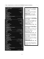
1
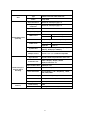
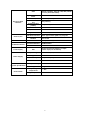
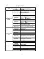
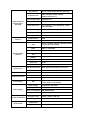
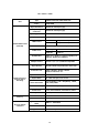
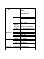
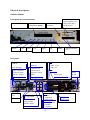
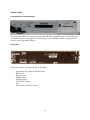
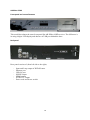
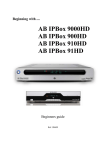
Digital HDTV receiver with Linux operating system AB IPBox 9900HD AB IPBox 9900HD plus AB IPBox 99HD AB IPBox 55HD User Manual www.abipbox.com 1 Introduction Thank you for purchasing our digital HDTV receiver. The receiver enables you to enjoy world of high definition television with excellent picture details and incredible surround sound. It also brings you an access to large amount of digital radio stations, Internet radios and other services. Thanks to AB Enigma2 HD operating system you can adjust your receiver to suit your personal needs and install new functions and modules. The receiver also enables playback of different multimedia files from built‐in HDD, other connected devices or via network. We wish you many pleasant experiences while using your receiver. 2 Content: Introduction 2 Safety Precautions 4 Technical specifications 5 Physical Description 14 Connection of AB IPBox HD receiver 17 Remote controller 19 Operation 20 Initial Setting 20 Channel list. 25 Program information bar of the channel (infobar) 26 Channels Searching 29 Tuner configuration 29 Automatic Scan 34 Manual scan 34 Adding channels into „Favorite“ lists (bouquets) 36 System setup 39 Allinone Panel 48 Recording 54 Timeshift 55 PIP (Picture In Picture) 55 Media Player 56 Timer 57 EPG (Electronic Program Guide) Standby / Restart 58 62 Conclusion 63 Installation of a new firmware Copyright 63 63 3 Safety Precautions Please read this manual thoroughly before the appliance is operated. Strictly follow all safety precautions! Install you receiver in dry environment, avoid any contact with water and humidity. Do not turn on the receiver after the contact with cold environment – condensated water may affect proper operation of the appliance. Wait several hours to dry up naturally. Do not put it near any heating sources. The appliance should not be exposed to dripping or splashing and no objects filled with liquid, such as vases, glasses, flowerpots should be placed on the appliance. If the appliance has been exposed to rain or water, or if liquid has been spilled or objects have fallen into the appliance, unplug the appliance from the wall outlet and refer servicing to qualified service personnel. Unplug the appliance from the wall outlet before cleaning. The appliance should be cleaned only with dry or slightly wet cloth. The appliance should be situated away from heat sources such as radiators, heat registers, or other appliances that produces heat. Slots and openings in the cabinet are provided for ventilation and ensure reliable operation of the appliance and to protect it from overheating. These openings should never be blocked or covered! The appliance should be operated only from the type of power source indicated on the marking label (100-240V 50-60Hz). Do not use the appliance when the power-supply cord or plug is damaged. Connect all other accessories to the appliance before connecting it to a wall outlet. Do not install and connect antenna during thunderstorm or high humidity. Be sure the antenna and cable system is grounded as to provide some protection against voltage surges and built-up static charges. Unplug the appliance from wall outlet and disconnect the antenna system if you are not going to use the appliance for longer period of time. Do not uncover the cabinet and do not conduct any repairs of the appliance! Any unauthorized repair may result to lose of warranty! There are not any fuses or user repairable parts inside the appliance. 4 Technical specification – comparison of AB IPBox HD models AB IPBox 9900 Plus HD 1st. tuner 2nd.tuner 2xCI CardReader HDD HDD bracket USB 2 RS 232 Display Scart RCA/YPBpBr Modulator Power Switch Flash Memory SPDIf Ethernet 0/12V 9900 HD 99 HD 55HD DVB-S2 embedded DVB-S2 embedded DVB-S2 embedded DVB-S2 P&P optional yes yes 2x 2x e-SATA/SATA e-SATA/S ATA yes yes 2x 2x yes yes VFD VF D DVB-S2 embedded DVB-S2 P&P optional no 1x SATA yes 1x no VFD DVB-S2 embedded no no 1x USB no 1x no 4 Digit LED 2x 2x yes yes yes yes yes yes 32MB 32M 256MB 25 yes yes yes yes yes yes 1x no no no 32MB 256MB yes yes no 1x no no yes 64MB 256MB yes yes no B 6MB Technical parameters of AB IPBox HD receivers: All AB IPBox 9900HD, 99HD and 55HD receivers are equipped with AB Enigma 2HD operating system. The AB IPBox 9900HD Plus receiver is standardly equipped with two DVB-S tuners that enables simultaneous watching and recording of 2 channels from different transponders/satellites. Technical parameters of the AB IPBox 9900HD Plus and AB IPBox 9900HD are the same. The only difference is that the AB IPBox 9900HD model is standardly equipped with just one DVB-S2 tuner and is equipped with connector for connecting another tuner: DVB-T terrestrial, DVB-C cable or DVB-S2 satellite. See table below for detailed technical specification. The AB IPBox 9900 models are equipped with 2 CI (Common Interface) slots and Conax card readers. All AB IPBox 99xxHD models are prepared for installation of internal 2,5“ SATA HDD up to 1,5 TB. 5 ABIPBOX 9900HD Plus Type CPU Data/Instruction Cache 32KB/16KB Input Connector IEC169-24 Female(F-type) X 2 Loop through Connector IEC169-24 Female(F-type) X 2 Input Signal Level -65 to -25dBm Frequency Range 950MHz to 2150MHz LNB Control Satellite 8PSK Tuner (DVB-S2) Waveform 22KHz Tone Symbol Rate DiSEqC Control Input Stream Profile & Level Input TS Data Rate MPEG Transport Stream & A/V Decoding Aspect Ratio Video Resolution Audio Decoding Memory 266MHz ST40-202 32bit RISC CPU Vertical 13V(400mA Max) Horizontal 18V(400mA Max) QPSK, 8PSK(C/KU band compatible) Frequency 22±2KHz Amplitude 0.6±0.2V QPSK( up to 45MS/s), DVB-S2 :QPSK(up to 36MS/S), 8PSK(up to 30MS/s) Version 1.0/1.1/1.2/USALS Compatible ISO/IEC 13818-2 Specification and H.264 MPEG-2 MP@ML, MP@HL, MPEG4 AP@HL/H.264 level 4.1 138Mbit/S max. 4:3, 16:9 with pan/scan vector 720 x 576(PAL), 720 x 480(NTSC), 1080i, 720P, 480i, 480P MPEG-1 Audio Layer 1,2, Musicam Audio Mode Stereo, Dual Channel, Joint Stereo, Mono Sample Rate 32, 44.1, and 48KHz Flash Memory DDR SDRAM 32MB 256MB (128MB + 128MB) 6 HDD e-SATA (1.5Gbps), 80/120/160/200/320GB and over (User Selectable) Digital interface for HDMI 1.1 with HDCP HDTV SCART I/F Storage & Rear connector CVBS & Audio R/L Out RCA (3 Ports) Component Out (YPbPr) RCA (3 Ports) RF-Modulator 0/12V Out Digital Audio Data In/Out Network Conditional Access Front Display USB Host Interface S/PDIF via Optical USB A-Type Female (USB 2.0) X 2 ports Ethernet RJ-45 (10/100BT) Common Interface 2 PCMCIA Slots Smartcard Interface 2 Slots VFD Vacuum Fluorescent Display as Alpha numeric style (14 dot matrix) AC100-240V~, 50/60Hz SMPS Power Consumption 30W (Standby:3W) Protection Size (W x H x D) Weight Environment Chinch 9 Pin D-Sub Type Physical Specification In & Out RS232C Input Voltage Power Supply TV & VCR (2 Ports) Operating Temperature Separate Internal Fuse and Chassis 340mm x 65mm x 250 mm 3.5Kg 0 ~ 45C Storage Temperature -40C ~ 65C 7 AB IPBox 9900HD Type CPU Data/Instruction Cache 32KB/16KB Input Connector IEC169-24 Female(F-type) Loop through Connector IEC169-24 Female(F-type) Input Signal Level -65 to -25dBm Frequency Range 950MHz to 2150MHz LNB Control Satellite 8PSK Tuner (DVB-S2) Waveform 22KHz Tone Symbol Rate DiSEqC Control Input Connector Loop through Connector Terrestrial OFDM Tuner Vertical 13V(400mA Max) Horizontal 18V(400mA Max) QPSK, 8PSK(C/KU band compatible) Frequency 22±2KHz Amplitude 0.6±0.2V QPSK( up to 45MS/s), DVB-S2 :QPSK(up to 36MS/S), 8PSK(up to 30MS/s) Version 1.0/1.1/1.2/USALS Compatible IEC169-2 female IEC169-2 male Frequency Range 50MHz to 870MHz Loop through Out Impedance 75 ohms nominal Band Width 7/8 MHz Carrier Mode 2k & 8k hierachical/non-hierachical mode Constellation Auto(QPSK, 16/64 QAM) Mode Rate Guard Interval Input Connector Loop through Connector Cable QAM Tuner 266MHz ST40-202 32bit RISC CPU Auto(1/2, 2/3, 3/4, 5/6 and 7/8) Auto(1/4, 1/8, 1/16 and 1/32) IEC169-2 female IEC169-2 male Frequency Range 47MHz to 862MHz Loop through Out Impedance 75 ohms nominal IF Bandwidth QAM mode Symbol rate 8MHz 16, 32, 64,128,256 QAM 0.87Mbaud~7Mbaud Max. 8 Input Stream Profile & Level Input TS Data Rate MPEG Transport Stream & A/V Decoding Aspect Ratio Video Resolution Audio Decoding Memory ISO/IEC 13818-2 Specification and H.264 MPEG-2 MP@ML, MP@HL, MPEG4 AP@HL/H.264 level 4.1 138Mbit/S max. 4:3, 16:9 with pan/scan vector 720 x 576(PAL), 720 x 480(NTSC), 1080i, 720P, 480i, 480P MPEG-1 Audio Layer 1,2, Musicam Audio Mode Stereo, Dual Channel, Joint Stereo, Mono Sample Rate 32, 44.1, and 48KHz Flash Memory DDR SDRAM HDD 32MB 256MB (128MB + 128MB) e-SATA (1.5Gbps), 80/120/160/200/320GB and over (User Selectable) Digital interface for HDMI 1.1 with HDCP HDTV SCART I/F Storage & Rear connector RCA (3 Ports) Component Out (YPbPr) RCA (3 Ports) RF-Modulator 0/12V Out Digital Audio Data In/Out Network Conditional Access Front Display USB Host Interface S/PDIF via Optical USB A-Type Female (USB 2.0) X 2 ports Ethernet RJ-45 (10/100BT) Common Interface 2 PCMCIA Slots Smartcard Interface 2 Slots VFD Vacuum Fluorescent Display as Alpha numeric style (14 dot matrix) AC100-240V~, 50/60Hz SMPS Power Consumption 30W (Standby:3W) Protection Size (W x H x D) Weight Environment Chinch 9 Pin D-Sub Type Physical Specification In & Out RS232C Input Voltage Power Supply TV & VCR (2 Ports) CVBS & Audio R/L Out Operating Temperature Separate Internal Fuse and Chassis 340mm x 65mm x 250 mm 3.5Kg 0 ~ 45C Storage Temperature -40C ~ 65C 9 AB IPBox 99HD Type CPU Data/Instruction Cache 32KB/16KB Input Connector IEC169-24 Female(F-type) Loop through Connector IEC169-24 Female(F-type) Input Signal Level -65 to -25dBm Frequency Range 950MHz to 2150MHz LNB Control Satellite 8PSK Tuner (DVB-S2) Waveform 22KHz Tone Symbol Rate DiSEqC Control Input Stream Profile & Level Input TS Data Rate MPEG Transport Stream & A/V Decoding Aspect Ratio Video Resolution Audio Decoding Memory Storage & Rear connector 266MHz ST40-202 32bit RISC CPU Vertical 13V(400mA Max) Horizontal 18V(400mA Max) QPSK, 8PSK(C/KU band compatible) Frequency 22±2KHz Amplitude 0.6±0.2V QPSK( up to 45MS/s), DVB-S2 :QPSK(up to 36MS/S), 8PSK(up to 30MS/s) Version 1.0/1.1/1.2/USALS Compatible ISO/IEC 13818-2 Specification and H.264 MPEG-2 MP@ML, MP@HL, MPEG4 AP@HL/H.264 level 4.1 138Mbit/S max. 4:3, 16:9 with pan/scan vector 720 x 576(PAL), 720 x 480(NTSC), 1080i, 720P, 480i, 480P MPEG-1 Audio Layer 1,2, Musicam Audio Mode Stereo, Dual Channel, Joint Stereo, Mono Sample Rate 32, 44.1, and 48KHz Flash Memory DDR SDRAM 32MB 256MB (128MB + 128MB) Digital interface for HDMI 1.1 with HDCP HDTV SCART I/F Digital Audio TV (1 Ports) S/PDIF via Optical 10 Data In/Out USB Host Interface Network Ethernet Conditional Access Front Display VFD Type Size (W x H x D) Weight Environment Vacuum Fluorescent Display as Alpha numeric style (14 dot matrix) AC100-240V~, 50/60Hz SMPS Power Consumption 30W (Standby:3W) Protection Physical Specification RJ-45 (10/100BT) Smartcard Interface 1 Slots Input Voltage Power Supply USB A-Type Female (USB 2.0) Operating Temperature Separate Internal Fuse and Chassis 340mm x 65mm x 250 mm 3.5Kg 0 ~ 45C Storage Temperature -40C ~ 65C AB IPBox 99HD, AB IPBox 55HD – basic features: AB IPBox 99HD and AB IPBox 55HD are equipped wit one built-in DVB-S2 tuner, the 99HD model is moreover equipped with a bracket for internal 2.5“ HDD SATA. AB IPBox 99HD and AB IPBox 55HD models (in comparison wit AB IPBox 9900HD model) are not equipped with: - Common Interface, - RF modulator, - 0/12V output, - YpBPr and composite A/V output, - e-SATA connector for external HDD, - AB IPBox 55HD is also not equipped with RS232 serial connector and does not support installation of HDD. Both models are equipped with: - just one Conax card reader, - just one Scart connector, - just one USB host connector (type 99 on front panel, type 55 on rear panel) There is no difference in picture and sound processing between AB IPBox 99HD/55HD and AB IPBox 9900HD. The AB IPBox 55HD receiver is additionally equipped with 64 MB Flash memory. 11 ABIPBOX 55HD Type CPU Data/Instruction Cache 32KB/16KB Input Connector IEC169-24 Female(F-type) Loop through Connector IEC169-24 Female(F-type) Input Signal Level -65 to -25dBm Frequency Range 950MHz to 2150MHz LNB Control Satellite 8PSK Tuner (DVB-S2) 266MHz ST40-202 32bit RISC CPU Waveform 22KHz Tone Symbol Rate DiSEqC Control Input Stream Profile & Level Vertical 13V(400mA Max) Horizontal 18V(400mA Max) QPSK, 8PSK(C/KU band compatible) Frequency 22±2KHz Amplitude 0.6±0.2V QPSK( up to 45MS/s), DVB-S2 :QPSK(up to 36MS/S), 8PSK(up to 30MS/s) Version 1.0/1.1/1.2/USALS Compatible ISO/IEC 13818-2 Specification and H.264 MPEG-2 MP@ML, MP@HL, MPEG4 AP@HL/H.264 level 4.1 Input TS Data Rate 138Mbit/S max. MPEG Transport Stream & A/V Decoding Aspect Ratio Video Resolution Audio Decoding Memory Storage & Rear connector Network Conditional Access 720 x 576(PAL), 720 x 480(NTSC), 1080i, 720P, 480i, 480P MPEG-1 Audio Layer 1,2, Musicam Audio Mode Stereo, Dual Channel, Joint Stereo, Mono Sample Rate 32, 44.1, and 48KHz Flash Memory DDR SDRAM 64MB 256MB (128MB + 128MB) Digital interface for HDMI 1.1 with HDCP HDTV SCART I/F Digital Audio Data In/Out 4:3, 16:9 with pan/scan vector TV (1 Ports) S/PDIF via Optical USB Host Interface USB -Type Female (USB 2.0) Ethernet RJ-45 (10/100BT) Smartcard Interface 1 Slots 12 Front Display LCD Input Voltage Power Supply Type Environment AC100-240V~, 50/60Hz SMPS Power Consumption 30W (Standby:3W) Protection Physical Specification Alpha numeric style Size (W x H x D) Weight Operating Temperature Separate Internal Fuse and Chassis 340mm x 65mm x 250 mm 3.4Kg 0 ~ 45C Storage Temperature -40C ~ 65C 13 Physical description: AB IPBox 9900HD Front panel and control buttons: Vacuum fluorescent alfanumeric display STANDBY MENU OK EXIT Left Card readers (insert card the way that golden chip is facing down) USB 2.0 host connector Right Up Down Common Interface (CA) Rear panel: LNB IN Loop Through IEC connectors (Tuner B input, DVB-T output) Ethernet Connector for connection of external e-SATA HDD RS232 port SCART VCR SCART TV Výstup HDMI USB 2.0. Optical audio S/PDIF output Fan Power cord RCA – outputs: YPbPr – component video output Y Video CVBS B Audio L R Audio R 14 RF Modulator TV output Antenna input Power switch AB IPBox 99HD Front panel and control buttons: This model has almost the same front panel like AB IPBox 9900HD receiver. The difference is behind the doors on the right side of front panel – the AB IPBox 99HD is equipped with just one card reader and USB port. Rear panel Rear panel consists of (from left side to the right): - Input and Loop output of DVB-S2 tuner RS232 port Ethernet port HDMI output S/PDIF output SCART TV output Fan Power cord and Power switch 15 AB IPBox 55HD Front panel and control buttons: This model has almost the same front panel like AB IPBox 99HD receiver. The difference is in using 4 digits LED display and absence of USB port behind the door. Real panel Rear panel consists of (from left side to the right): - Input and Loop output of DVB-S2 tuner Ethernet port USB 2.0 port S/PDIF output HDMI output SCART TV output Power cord and Power switch 16 Examples of possible connection of AB IPBox HD receiver: Example 1: TV USB flash Basic connection for High Definition display: - Connect your satellite dish to input LNB IN of DVB-S2 Tuner (1). - If the receiver is equipped with second Tuner, connect output from corresponding antenna dish to LNB IN (2) input (terrestrial antenna if it is DVB-T tuner or satellite antenna if it is DVB-S2 tuner). - Connect your TV to the receiver via HDMI cable (some older type of HD ready TVs may not contain HDMI connector, in such a case use YPbPr connector). - Connect your home cinema (A/V receiver) via digital optical S/PDIF output. - Connect Ethernet output to your home network – if possible to the router. - You can connect memory USB device with multimedia content to USB port. 17 Example 2: Basic connection for older type of TVs without HDMI connector – displays only in SD (Standard Definition) quality! TV AV 1 Videorecorder TV (AV 1) USB flash - Connect your satellite dish to input LNB IN of DVB-S2 Tuner (1). - If the receiver is equipped with second Tuner, connect output from corresponding antenna dish to LNB IN (2) input (terrestrial antenna if it is DVB-T tuner or satellite antenna if it is DVB-S2 tuner). - Connect your TV to the receiver via SCART cable (or 3x cinch). - Connect your home cinema (A/V receiver) via digital optical S/PDIF output or Cinch outputs AUDIO L/R (only stereo audio). - Connect Ethernet output to your home network – if possible to the router. - You can connect memory USB device with multimedia content to USB port. - You can use SCART AV output for connection of e.g. DVD recorder. 18 Remote controller description Note: The remote controller is not compatible with older type of AB IPBox receivers (AB IPBox 91HD, 910HD, 9000HD). STANDBY MUTE Files list TV channels Browser ‐ if installed Radio channels EPG Teletext EXIT MENU Cursors: left, right, up, down PAge Up / Down PLAY OK Not used Recording Stop FW REW Not used Pause ‐ Timeshift Color function buttons Swithing over the channels Volume Up / Down Info HELP Alphanumeric buttons Recall – back to previous channel Not used (restart of card reader) Picture resolution Picture size and ratio swithing over Subchannels (Sky De) Alternate audio track Subtitle Menu Note: Picture resolution button is to quick switch over the picture resolutions. If you set HDMI 1080i – picture is simultaneously transmitted onto component output in 1080i resolution. Press the button again to select SD PAL; output is transmitted on SCART and HDMI in 576i resolution. Press the button once more to select 720p, Scart output is disconnected; picture is transmitted on component and HDMI outputs in 720p resolution. Press the button for the third time to set 1080i again. 19 Operation: AB IPBox 9900HD PVR with AB Enigma2 HD firmware AB Enigma2 HD firmware was developed to enable simple and comfortable control of all functions of your receiver. Powering Up the receiver a) Before connecting the power cord, connect to the receiver your other components and antenna (see examples in previous chapter). Finally connect the power cord to a suitable wall outlet. b) Turn on your TV and select HDMI input in its menu (or different corresponding input according to your real physical connection). c) Press the POWER switch on the rear panel to turn on the power. Time indicator is displayed. Press the STANDBY button on the front panel or RC. Starting the receiver and booting the system may last about 2 minutes; initial logo is displayed during this process. Wait till the end of starting. Initial Setting If you do not see any picture on your TV, wait and check the message on the display. The receiver automatically switches over all outputs. Press the OK button when you see corresponding output on the display. Outputs are continuously switched over in following order: Component – SCART – HDMI. Select SCART (SD-PAL 50Hz) if you use SCART – SCART connection. Select 1080i if you use Component connection. Select 1080i if you use HDMI connection. The refresh frequency menu appears after selection of HDMI. Set 50 or 60Hz according to your TV. TV sets commonly used in Europe use 50 Hz – confirm the selection by pressing the OK button. If you accidentally set incorrect resolution and there is none or incorrect picture on your screen you can repeat the setting up: - Turn off the power of your IPBox by pressing the switch on the rear panel. - Turn on the receiver and watch the display. - Press and hold for a short while the MENU button on the front panel when IPBOX 9900 message appears on the display. - Available resolutions are displayed (SD-PAL, 720p, 1080i-50Hz, 1080i-60Hz…) - Use Right – Left arrow buttons to select corresponding resolution and press OK. New booting with new settings starts. - Wait until Installation wizard (guide) appears. 20 Screen test – “yes”, “no” After setting up the video resolution you will be asked if you want to set up the picture parameters. Select “no” to skip the menu or “yes” to adjust level of Brightness: Follow the instructions displayed on the screen. You can also return to this menu anytime later. Press OK to confirm your setting – menu for adjusting of Contrast appears. Adjust the level of Contrast and press OK. Language selection Select desired language and press OK. 21 Basic setting installation menu (preinstalled channel list) appears on the screen. If none setting is available, skip the menu otherwise choose desired one and press OK. Note: You can download Setting from the Internet or install it from your PC. Configuration Mode You can set up your antenna (outside dish) in this menu. There is „not configured“ setting preset in tuner configuration menu. Set desired configuration of tuner (tuners). „Simple“: Setting for using two LNB converters (or so called monoblock) connected DiSEqC switch ½ . Basic setting: Input 1 = A : Astra 19,2E. Input 2 = B : Hotbird 13E. Use cursor buttons to change satellites for A or B positions if your dish is aimed at different satellites. We recommend not changing the other settings. These are preset for the most common type of LNB - Universal. You can change configuration of tuners later on in the menu of the receiver. If your receiver is equipped with two tuners, second tuner is in the menu marked as tuner B. Second tuner can be also installed into your receiver additionally – type according to your requests: DVB - S2 satellite DVB – T terrestrial DVB – C cable The main advantages of using two tuners are wider channel list and possibility of simultaneous watching/recording of program from different satellites (services). Example of setting of DVB – T tuner: Configuration mode Terrestrial provider 5V active antenna Press OK to confirm. „enabled“ „21-69k“ “on” (if you use active antenna otherwise set “off”). The question message appears on the screen: „Do you want to install default sat list? “ Select „yes“ to choose one of following four preset satellites: Astra2 – 28.2E, Astra1 – 19.2E, Astra 3 – 23.5E, Hot Bird - 13E Select “yes” for satellite that should be installed. 22 Parental control “yes” – “no” Select “yes” to enter to the menu for setting up the parental control. Menu for inserting PIN code appears – insert preset code (0000). In the following window you can change PIN according to your choice: insert new PIN into first line and write down the same code into second line to confirm. Press Green function button to save new PIN code. You can block selected channels in the list by using PIN code. Press OK to continue the wizard. Network configuration Use interface – set up „yes“ Use DHCP – set up „yes“ if your receiver is connected a router that supports Auto DHCP function. In such a case the network will be automatically set according to data from the router. 23 For manual configuration of the network please set the item “Use DHCP” - „no“ . Set up appropriate values for parameters IP Address, Netmask, Use a Gateway and Gateway. Netmask value must be the same as it is in your computer; IP Address must differ from IP Address of your PC in last three digits. Example: IP address of your PC is 192.168.0.24, IP address of your receiver is 192.168.0.25. You can find out IP address of you PC by ipconfig /all command. (In your PC: Programs – Accessories – Command Line – write down: ipconfig /all and press enter. Network configuration of your PC should be displayed). Inserted IP Address must be unique – no other device connected to your network can use the same IP address. Press OK to finish the setup. Window asking the question if you want to activate the network will be displayed. Select “yes” and press OK. Two information windows about activation of the network will be displayed. Last window shows whether the activation is successful. You can also configure your network later on through the menu. Press OK to finish installation wizard. List of channels appears on the screen. If no setting has been installed the list is empty. 24 Channel list Channel sort, favourites groups - bouquets. Press OK and Blue function button to display „Favourites“ list. Favorites: Select desired Favourite group (e.g. Sport) and use cursor buttons to select desired channel. Press the OK button – selected channel will be displayed (if it is FTA channel or you have the authorization for wathing the channel). You can swith over the channels also without the menu by direct inserting corresponding number of the channel. 25 Selection of a channel from favorites Select desired channel in the favourite group (e.g. Eurosport HD) and press OK. List of channels disappears. Selected channel with information bar will be displayed. Program information bar of the channel (infobar) - description of displayed indications Actual time Position of the satellite Bar indicator of elapsed time of the program Channel Number Name of the channel Actual date Services symbols EPG Encrypted Teletext Subchannels Indicator of recording HD broadcasting Multi language audio Audio AC3 EPG 1st line: start time of actual program, its name and its duration time. EPG 2nd line: next program Widescreen 16:9 Video resolution Active tuner DVB-S A Provider name. 26 SNR = Signal/Noise Ratio. AGC = Automatic Gain Control. BER = Bit Error Rate – ideal value is zero. Higher value means „squered“ picture. Selecting a channel from ALL Press OK to display list of channels. Press Red function button to display list of „All“ channels. Use cursor buttons to select desired channel and press OK. Selecting a channel from Satellites list Press OK to display list of channels. Press Green function button (Satellites) to display list of available satellites. Use cursor buttons to select desired satellite and channel and press OK. Channels can be sorted into three subgroups: Services – All channels from selected satellite in alphabetical order. Providers – Displays list of providers. Select a provider and press OK. Channels of selected provider will be displayed. New – Only new channels after last searching will be displayed. 27 Selecting the channel from Provider list Press OK to display list of channels. Press Yellow function button (Provider) to display list of available providers. Use cursor buttons to select desired group (e.g. Skylink) and press OK. Names of providers and groups of channels are created automatically during searching accordingto NIT parameters from satellite and can not be changed. Example of channels by ARD TV provider from Astra 19,2E satellite. 28 Searching (Menu – Setup – Service Searching) Select „Service Searching“ and press OK to display „Tuner configuration“ menu. Tuner configuration (Menu – Setup – Service Searching - Tuner configuration) If you use also Tuner 2 in your AB IPBox it must be configurated separatelly. Example shows DVB-T tuner as Tuner 2. Choose Tuner Type and configuration of installed tuners is displayed in this menu. Select the tuner to be configured and press OK. 29 Tuner configuration for motor with USALS (GOTOX) system – example: Configuration Mode – advanced Example: Satellite – All satellites 1 Use cursor buttons to select desired satellite. LNB number is automatically allocated to selected satellite (e.g. LNB 33). All the data essencial for connecting your dish to USALS motor are preset in the table and if you use Universal type of LNB it is not needed to change them. Set up your geographical position (accuracy 0,100° ) In example: Longitude: 14.800° East Lattitude: 52,000° North Next page of the menu: Press OK to save the settings. Configuration of Tuner B. Example of configuration of DVB-T tuner: Configuration Mode – enabled Terrestrial provider – 21-69k Remain item „Enable 5V for active antenna“ set to „off“. Change it onto „on“ in a case that you use active antenna with built-in amlifier feeded via coaxial cable. 30 Tuner configurations for connection with DiSEqC switch for 4 satellites: Configuration Mode – advanced Selected satellite – 19,2 ASTRA LNB LNB 1 LNB convertor for Astra 19,2E is connected to input 1 = A= AA of DiSEqC switch. DiSEqC mode - selected 1.0. Commited DiSEqC command AA Configuration for second satellite: Selected satellite – 13E HOTBIRD LNB LNB 2 LNB convertor for HotBird 13E 2E is connected to input 2 = B = AB of DiSEqC switch. DiSEqC mode - 1.0 Commited DiSEqC comm. – AB Configuration for third satellite: Selected satellite – 23,5E ASTRA3 LNB LNB 3 LNB convertor for ASTRA3 23 is connected to input 3 = C = BA, AB of DiSEqC switch.. DiSEqC mode - 1.0 Commited DiSEqC comm. – BA Configuration for fourth satellite: Selected satellite – 0,8W THOR LNB LNB 4 LNB convertor for Thor 0,8W is connected to input 4 = D = BB of DiSEqC switch. DiSEqC mode - 1.0 Commited DiSEqC comm. – BB If you use switch with more then four inputs, set up „DiSEqC mode“ parameter - 1.1. 31 Manual configuration of DiSEqC 1.2 motor (Menu – Setup – Service Searching – Positioner setup) This setting is used only for DiSEqC motors without USALS system. Tuner is set for DiSEqC 1,2 , USALS is turned off and satellites to be aimed with motor are selected. „Tune“ – press Red function button to display menu for entering satellite and TP to be searched. Press OK for return to setup menu. You have to set up corresponding transponder for every satellite and save its position number. Positioner movement – use color function buttons (according to description) to control movement of the motor. Press the button once to start movement, press it for the second time to stop the movement.. Positioner fine movement step by step movement. Try to reach maximum value of SNR parameter. Positioner storage – press Green function button to save the position. Set limits – Setting up the east and west Service searching (Menu – Setup – Service Searching – Default services lists) This menu enables installation of basic (default) setting for basic satellites (Astra 28,2E, Astra 19,2E, Astra 23,5E and HotBird 13E) – same way like during initial configuration. Warning! Actual setting in your receiver will be removed during Default setting installation! If you need setting for more satellites you can install it as a plugin: Plugins (Menu – Plugins – Download Plugins) Press GREEN function button „Download Plugins“. Wait until downloading catalogue of plugins from the Internet. Select Settings item and press OK. 32 Select desired setting and press OK. Use the same way to install other plugins. You can also use DreamboxEdit software in your PC to install and edit the setting. 33 Automatic Scan (Menu – Setup – Service searching – Automatic Scan) Clear before scan – „yes“: Removes all channels searched before. Scan Tuner A (DVB-S2)-„yes“: Runs searching on all available satellites according to setting of the tuner (if you use a motor it can last several tens of minutes). Manual scan Tuner A or B Type of scan: Single satellite – select one sigle satellite to be searched on and press OK for starting the searching. Single transponder - insert parameters for one particular transponder and press OK: System – DVB-S or DVB-S2 . Satellite – name of satellite. Frequency – frequency of TP. Symbol rate Polarity FEC – set the right value or set „Auto“ Modulation: QPSK – 8PSK Network scan – if set to „yes“ it searches on all TPs of corresponding provider (if the service is supported by the provider). Only Free scan – searching only for FTA channels. Press OK to start searching. You can find specific parameters of satellites and transponders e.g. on: http://kingofsat.net , http://lyngsat.com , www.parabola.cz and other web pages. 34 Satellite Equipment setup (Menu – Setup – Service Searching – Satellite Equipment setup) We strongly recommend not changing the parameters in this menu if you are not an expert! Satfinder (Menu – Setup – Satfinder) Satfinder menu is used to help to adjust alingment of your antenna dish. SNR = Signal/Noise Ratio – quality of the signal. AGC= Automatic Gain Control – strength of the signal (including noise and interference) BER= Bit Error Rate To achieve the best quality reception try to reach maximum SNR value and zero BER. Tune – Manual transponder = use cursor and numerical buttons on RC to set up parameters manualy: Satellite – select corresponding satellite. System, Frequency, Symbol rate, Polarity and FEC – set up manualy according to parameters of transponder on witch you are going to check quality of the signal. or: Tune – Preset transponder = It sets up default (preset) transponder with all its parameters. Adjust the dish position very slowly. If the signal quality is sufficient for searching the channels, marker is displayed in Lock window. 35 Adding channels into „Favorite“ lists (bouquets) These lists (bouquets) are used for common simple orientating among your favorite channels. Select „New“ – new searched channels. New searched channels are automatically added to „All“ list, corresponding „Satellites“ and „Provider“ lists. Press OK to open the channel list. Use color function buttons to display corresponding list: All, Satellites, Providers, Favourites. Use cursor buttons to select the channel you want to add to „Favorites“ list. Press MENU button to open „Channellist menu“ menu… Channellist menu Select „add service to bouquet“ and press OK. „Select bouquet“ menu is displayed. Use cursor buttons to select desired bouquet group you want to add selected channel in and press OK. The channel will be added at the end of the bouquet list. Press EXIT to finish adding channels to bouquet list. 36 Changing position of channels in bouquet list OK – Blue button – select a bouquet containing the channel you want to change position in the list – OK. Select the channel to be moved. (The list is always opened on the first channel of the list. Press cursor button Up once to jump on the last channel in the list.) Press MENU button. Select „Channellist menu“ and press OK. Select „enable move mode“ and press OK... By pressing OK you return to the bouquet list – moving of channels in the list is enabled. Select the channel and press OK – the channel in the list is highlighted. Use Up/Down cursor buttons to move highlighted channel. Select desired position in the list and press OK. You can move channels in the list until the „enable move mode“ item in „Channellist menu“ is active. Press EXIT button to return to the last watched channel. 37 Direct selection of channel by numeric buttons. Channels from all bouquets are sequenced in „Favorites“ list according to their numbers. It enables their direct calling by entering their number (the number is also shown on infobar). We do not recommend adding the same channel to several bouquets. It will cause that one channel will be stored under several different numbers! If the channel is contained in more bouquets it is possible to use only the number shown on infobar for direct selection. Creating a new bouquet Use „Channellist menu“ menu to create a new bouquet. (OK – Blue – Blue – MENU) Select “add bouquet” and press OK. „Please enter name for the new bouquet“ windows appears on the screen. Use alphanumeric buttons on RC to write down a name of new bouquet into „Input“ window: Pg/Up - removes letter in front of the cursor Pg/Down – removes letter behind the cursor 1 – space, 1. 2 – a, b,c, 2, A, B, C 3 – d ,e, f, 3, D, E, F 4 – g, h, i, 4, G, H, I 5 – j, k, l, 5, J, K, L 6 – m, n, o, 6, M, N, O 7 – p, q, r, s, 7, P, Q, R, S 8 – t, u, v, 8, T, U, V 9 – w, x, y, z, 9, W, X, Y, Z 0-. ,?´+“0-()@:_/ Recal - . , ? ´ + “ 0 - ( ) @ : _ / Writing the name of new bouquet: 38 Press OK after finishing the writting. New bouquet will be added on the end of the list. To change its position in the list activate „move“ mode in service menu. Select the bouquet to be moved and press OK. Use cursor buttons to find a new position and press OK. System setup (Menu – Setup – System) To reach best performance of your receiver it is very important to set up its system properly. Use Down cursor button to list in next page of system menu. System menu - next page: 39 AV Setting (Menu – System – AV Setting) Select first item in System menu (A/V Setting) and press OK. Menu for setting up audio/video appears. Use cursor buttons to select desired item (parameter) and press OK. Use Left/Right cursor button to set selected parameter. Video Output: HDMI, HDMI-PC, Component, Scart Mode: 1080i, 576p, 720p Refresh Rate: 50 Hz for Europe, 60 Hz for USA Display 4:3 contend as: Pillarbox, Full screen, Wide Zoom, Pan & Scan Display 16:9 contend as: Letterbox, Full screen, Pan&Scan Color Format - Video RGB, 4.2.2, YUV. Audio Source - PCM – analogue, SPDIF = digital optical output AC3 default – permanently preset multichannel digital audio source. Options „yes“ – „no“. Recommended „no“. AC3 downmix – audio downmix on analogue outputs – „yes“ General AC3 Delay – use numerics to set up the parameter General PCM Delay – – use numerics to set up the parameter. Recommended „75“. Press GREEN function button to save your settings. 40 Language (Menu – Setup – System – Language) Use Up/Down cursor buttons to select desired language. Press OK to confirm your selection. Customize (Menu – Setup – System – Customize) This menu contains detailed system settings you can adjust. Do not change the setting of any parameter if you are not absolutely sure. Customize menu Page 1 Setup mode Simple, Intermediate, Expert. Default setting of the item is „Intermediate“. Use Left/Right buttons to set up the level of setting up your receiver. Change the „Setup Mode“ back to „Intermediate“ and press Green button and OK. It enables direct access to PLUGINS download from the menu. 41 Customize menu Page 2 Timezone (Menu – Setup – System – Timezone) Use Left/Right cursor buttons to adjust Timezone according your location. Correct setting up of Timezone is essential for correct function of automatic setting of time, EPG and recording timer. RF output (Menu – Setup – System – RF output) Setting up parameters for modulator. Set up „on“ to enable RF modulator. Set up number of UHF channel for modulator in the line „Channel“. Use Left/Right buttons to adjust frequency (Finetune). It is possible to use modulator for picture transmission only with mono sound and when SD-PAL 576 video resolution is used. 42 Harddisk (Menu – Setup – System – Harddisk) Harddisk setup – set up sleep time for your HDD in minutes. Initialization – select this item and confirm the selection to start formatting of your internal HDD or external USB memory disk (linux ext3). All data will be removed! After installing a new hardisk into your receiver it is necessary to format the disk to create essential file system. Filesystem Check –launches check of your HDD. We recommend conducting the check at least once in two months. It can last several minutes depending on the size of your HDD. Network Configuration: (Menu – Setup – System – Network Configuration) Opens menu with following options: Adapter settings – setting up parameters of network adapter. Nameserver setting – setting up DNS. Network test – conduct the test after setting up the parameters and connecting to the network. Correct contingent mistakes according to result of the test. Restart network – use after correcting the settings after faulty test. Network Wizard helps to connect to the network. 43 Adapter settings Possible example of setting of network parameters: Use interface: yes Use DHCP: no IP Address: must be from the group used in your network Netmask: the same address as in other devices connected to the network Use a gateway: yes Gateway: IP address of gateway Network Wizard helps you to set up the network by means of OSD information on the screen of your TV. Press OK to confirm your setting. Press BLUE function button to open DNS – nameserver setup menu. Keyboard (Menu – Setup – System – Keyboard) Use Left/Right cursor buttons to select keybord type of your IP box. Press Green function button to save the setting. Recording paths (Menu – Setup – System – Recording paths) Menu for setting up the path (locations on the disk) for your recordings. Select the item and press OK to open submenu for setting the location. 44 Selection of location of records for instant recordings A device you want to save your recordings on must be active – mounted on your receiver. Use BLUE function button (Remove Bookmark) to remove active path (location). Press OK to confirm and return to the Location menu. Select desired valid memory device and press Blue function button (Add Bookmarks). Select a folder for storage recordings. Press GREEN function button to confirm your setting and return to Recording paths menu. Press GREEN button once more to save the setting. Video Fine Tuning: (Menu – Setup – System – Video Fine – Tuning) Follow instructions on the screen of your TV to adjust „Brightness“ and „Contrast“ parameters. 45 Skin (Menu - Setup – System – Skin) Use cursor buttons to select a skin – graphical backround of the menu of your receiver. Small overview of particular skin is shown on the right side of the screen. Select desired skin and press OK to activate it. Additional skins can be installed as Plugins. Permanent Clock (Menu – Setup – System - Permanent Clock) Select „Activate permanent clock“ and press OK to activate permanent display of time clock on the screen of your TV. Select „Change permanent clock position“ and press OK to change position of the clock on the screen. Use cursor buttons to adjust the position. 46 Crashlog settings (Menu – Setup – System – Crashlog settings) Crashlog (system failure extract notes) setting can be done in this menu. There is no purpose for common user to deal with it. Cleanup settings (Menu – Setup – System – Cleanup settings) First line – activate or deactivate Cleanup Wizard (warning when free space of internal memory is below the value set in the second line): „yes“ – „no“ We do not recommend to lower the value. 47 Allinone Panel Aspect Ratio – consequently press Green function button to adjust Aspect Ratio for SD channel. Direct changing the Aspect Ratio = middle button on the second bottom line of your remote controller. Sleep timer – press Yellow unction button to activate menu for setting up Sleep timer (automatic shut down of your receiver after elapsing a set time). Skin Selector – press Blue function button to display list of all available (installed) skins. Use cursor buttons to select desired one. Sleep Timer (Menu – Allinone Panel – Sleep Timer) Use numeric buttons to set up „Shutdown Ipbox after“ time in minutes. Press Red function button to enable timer. Consequently press Green function button to set up Sleep timer mode (action). Consequently press Yellow function button to set up whether to ask before shutting down or not. Skin Selector (Menu – Allinone Panel – Skin Selector) Displays list of all available (installed) skins. Use cursor buttons to select desired one. You can see small overview on the right side of the screen. 48 Select Var (Menu – Allinone Panel - Select Var) You can set up one of the three memory medias for storage of setting and plugin files (var): Flash – internal memory – usually sufficient for troublefree operation (with limited number of installed plugins). USB – external USB flash memory – enables installation of more number of plugins – if demanded. Hdd – also enables installation of more number of plugins. Main disadvantage is that in that case HDD is permanent turned on (running). Script executor (Menu – Allinone Panel - Script executor) You can add some other standardly not installed functions to your receiver by installing so called „scripts„ – short created programs saved in /var/sbin/ folder. List of all available scripts is displayed on this menu. Use cursor buttons to select one and press Red function button (Execute) to run it. Common Interface (Menu – Allinone Panel - Common Interface) Common Interface is interface for inserting encrypting modules with corresponding access card to decode pay television. It is possible to use several types of modules e.g. Cryptoworks, Irdeto etc. And also programmable modules. Insert CI module. Corresponding menu of inserted module is displayed. You can initiate the CI module from the menu. 49 Image Setup (Menu – Allinone Panel - Image Setup) Snapshot and Lcd Setup – not active. It is prepared for further development. Network Setup – opens menu for setting up Ethernet. Software Manager opens menu for management, backup and installation of software. Software Manager (Menu – Allinone Panel - Image Setup - Software Manager) Install – extensions opens menu „Extensions management“ for downloading list of plugins from the Internet from preset servers. Software update opens menu for updating installed firmware from the Internet. Software restore opens menu „Image upgrade wizard“. 50 Software restore - Image upgrade wizard Follow the instructions on the screen. Select „OK, guide me through...“ and press OK to activate the wizard or select „Exit the wizard“ and press OK to exit. Select memory media for storage backup files – the corresponding folder path is displayed on the LCD display of your receiver: Harddisk /media/hdd/ Network Mount /media/net/ Temporary Folder /tmp/ (Example on the picture also USB) USB Mass Storage /autofs/sdb3/ Image upgrade wizard – page 2: Press OK to run backup saving. After successful action an information window appears. Press OK to continue the upgrade. Note: It is good to use USB memory (flash) when you want to set up the same way several receivers. In such a case setting up can be conducted simply by „Backup restore“ function. Take care of consumption of used USB flash memory for backup – both USB ports are protected against overloading! Use USB HUB with external power supply for USB flash memory devices with higher consumption. Flash format - FAT32 or format USB disk in the Ipbox - Linux. Ext3. 51 Image upgrade wizard –successful backup message screen: After image upgrade you can restore your settings with „Backup restore“ function. Image Infos (Menu – Allinone Panel - Image Infos) Use cursor buttons and OK button (or numeric buttons for direct selection) to display corresponding information window: = Image Info (firmware information) = Free RAM memory = Free HDD memory = Free USB memory = Free Flash memory = Top (info about running files and its locations) = Process List (info about running processes) = Mount (info about mounted accessories) = LAN setting info (Ethernet setting) Press Red function button (Back) to leave the menu. 52 System Infos (Menu – Allinone Panel - System Infos) Use cursor buttons and OK button (or numeric buttons for direct selection) to display corresponding information window: = DvbSnoop Infos (not active, prepared for future development) = CPU (processor information) = MemInfo (memory information) = Modules = Graphics Mode = Mtd (from mtd0 to mtd4) = Partitions = Swap (size, type and priority) = Uptime = Kernel (Linux version, author, release date) Menu config (Menu – Allinone Panel - Menu config) Activates/deactivates whether to display the option in the menu or not. 53 Subtitle Use cursor buttons to select desired subtitle and press OK. To enter this menu directly, press „Subtitle“ button on your remote controller (middle button on upper line of RC). Recording The AB IPBox is capable of recording selected programs and saving them on built-in hard disc or connected memory device with sufficient memory capacity. Instant recording of just watched program Press REC button, a confirmation window appears. Use cursor buttons and OK or numeric buttons to select a type of recording (finish time). Recording starts immediately after the selection (except for option “don’t record – this option cancels recording). Recording of channel different from just watched one The IPBox enables watching a program on a channel while recording different program on different channel. Capability of this function depends on tuners configuration in your receiver. If your receiver is equipped with only one tuner, it is possible to record and watch different channel but only from the same transponder . If your receiver is equipped with two tuners, it is possible to watch one channel and record two different channels from two different transponders. 54 Finishing the recording – press REC or TV button to open menu. If recording more programs, select the one to be finished and press OK. Deleting records Press FILES button to open records files list. Use cursor buttons to select particular file and press MENU. Select “Delete” option and press OK. Confirmation window appears – select “yes” and press OK. Selected file will be removed. Records (files) can be deleted only one by one. Timeshift Actual watched program is permanently automatically recorded. If you have to interrupt your watching and you do not want to miss the program, just press PAUSE button. Playback of the program will stop (freeze) but background recording will persist. After coming back to your TV, just press PAUSE button to continue playback from the stopped point (with corresponding time shift against real broadcasting). Pressing STOP button will terminate the timeshift playback – realtime playback will start. PIP (Picture In Picture) This function is available only during watching standard resolution program. Press BLUE function button to open the menu. Press BLUE button again to activate PIP function. Press OK to open channel list. Active channels are highlighted. Select the program for PIP function and press OK. Originally watched program will be displayed in small window; new selected program will be displayed regularly (full screen). Press BLUE and YELLOW buttons consequently to switch the channels. Press BLUE button twice to terminate PIP function. 55 Formatting of USB flash disk Use any of USB connector on your IPBox for connection of USB disk. Enter menu: Menu – Setup – System – Hard disk – Initialization. Select corresponding USB disk in the list and press OK. A confirmation window appears. Select “yes” to confirm your selection. Warning: Be careful - all data stored on the disk will be erased during initialization (formatting)! Disk will be formatted in linux ext3 system. Short (direct) selections: BLUE button and then 1 = opens Sleep Timer BLUE button and then 2 = opens Netcaster (internet radio plugin) BLUE button and then 3 = opens Software management Media Player The Media Player enables playback of media files stored on connected USB devices or devices connected through the network. List of connected (available) media devices are displayed in this menu Select desired device (memory) and press OK. Folder structure is displayed. Select a folder to display its content – media files to be played. Example: SAMSUNG HM250HI - folder “movie“ 56 Select desired file from „movie“ folder and press OK to play selected media file. Press STOP button to stop playback and return to the file list. Press EXIT to leave the menu and return watching last watched channel. Timer Enter Timer menu and press GREEN function button to open menu for setting up a new timer. Use alphanumeric buttons to enter „Name“ of the timer. Use Left/Right buttons to set up Timer Type (timer action: record or switch over). Use Left/Right buttons to set up Repeat Type: once, daily, weekly or user defined. Use alphanumeric buttons to set up Date, Start Time and End Time of the timer. Set up Channel, Location, After event options and press GREEN function button to save the timer setting. It is also possible to activate a timer directly from EPG (Electronic Program Guide) – see text bellow. 57 EPG (Electronic Program Guide) Press Yellow function button to display EPG of actually watched channel (if the channel provides EPG information). Press BLUE function button to open Multi EPG, bouquet list is displayed. Select desired bouquet and press OK... 58 Single EPG Recording of a program through EPG of the channel: Use cursor buttons to select a program you want to record. Press GREEN button (Add Timer), „Input Timer“ window with information from EPG is displayed. Use GREEN button to save the timer. Use RED function button to cancel the timer. Program that is set for timer recording is marked by clock symbol in the list. Press GREEN button in EPG list to remove marked timer - confirmation is needed. Multi EPG menu Press BLUE function button to open Multi EPG, bouquet list is displayed. Select desired bouquet and press OK.. Multi EPG menu is displayed. EPG information of actual running program of all channels in the bouquet (if the channel provides EPG) is shown. Use BLUE function button (Next) to display following programs, use YELLOW function button (Prev) to show previous programs. Use cursor buttons to select a channel – program and press GREEN function button (Add Timer) to set up the timer. Program is in the list marked by a clock symbol. If EPG information of your desired channel is not displayed the channel probably does not support EPG function. To set up planned recording on such a channel, you have to use „manual“ Timer (see corresponding chapter). EPG infos are mostly displayed just for channels of actual TP/Provider. Please, wait for a while until all channel’s EPG is displayed (if it is broadcasted). 59 In this menu you can see a list of all set timers showing its status. Use RED function button (Delete) to remove selected timer. Use YELLOW function button (Disable) to disable (deactivate) selected timer. Press YELLOW button again to enable the timer. Use GREEN function button (Add) to add a new timer. Default setting (Menu – Setup – Default setting) Choose whether you want to install selected „Default setting“ or not („yes“ – „no“) and press OK. Installation of the default setting will start immediately. Actual installed setting in your Ipbox will be erased and replaced by the default one. Factory reset (Menu – Setup – Factory reset) Select whether to conduct Factory reset or not („yes“ – „no“) and press OK. When selected „yes“ all your configuration data including bouquets, services, plugins etc. will be lost. All the configurations and installations will have to be done once again. The IPBox will automatically restart the system after Factory reset. 60 VCR scart VCR SCART connector provides video signal only when video resolution is set up on „576“ (PAL). Use first right button at second button line of the remote controller to set up the video output. Press EXIT to exit. Information Service = information about actual received service. About = hardware and firmware information. Service (Menu – Information – Service) Press RED function button to display information about actual running service (channel). Press GREEN function button to display PID information. Press YELLOW function button to display information about the transponder of actual service. Press BLUE function button to display tuner status information. 61 About (Menu – Information – About) At this window you will find information about: - firmware used in your IPBox (Enigma, Image), - used processor - tuners installed in your IPBox - hard disk (type, capacity and free space). Standby / Restart Use the menu or press and hold for a while STANDBY button on your remote controller to open Standby/Restart menu. Select desired type of action and press OK: Sleep Timer – opens Sleep Timer menu for setting up a time period. After elapsing the time, your receiver will be automatically shut down.. Standby – select this option to turn off your receiver into Standby mode. Restart – select this option to restart the system of your Ipbox. After restart, the receiver will come back to the same mode as it was before the restart. Restart GUI – restarts only Enigma2 (Warm reboot.) Deep Standby – select this option to turn off your receiver into Deep Standby mode. 62 Conclusion AB IPBox team consecutively improves and develops firmware for AB IPBox receivers. We try to create new useful functions and expand capability of the IPBox receivers. Thanks to open architecture of used operating system Linux, also anonymous users can participate on the development. Latest software and information can be found on our technical support web page (http://download.abcom.sk/) or on other independent servers and forums. Installation of a new firmware: Enigma2 firmware for AB IPBox 99xx receivers contains following two files: usb_rootfs.img usb_kernel.img There is a difference between firmware for AB IPBox 55HD, AB IPBox 99HD and 9900HD! They cannot be exchanged! Make sure, that you are going to install a correct firmware into your IPBox. 1. Copy both files (do not change the names) from your PC into main (root) folder of your USB flash disk (FAT32 or linux ext3. format). 2. Connect the USB disk with the files to USB connector on front or rear panel of your receiver. 3. Turn off the power by using power switch on the rear panel of the receiver. 4. Wait approximately 3 secs and turn on the power back. Watch the display. When message „loader…“appears on the display, immediately press and hold „Standby“ button on front panel. Hold until “USB UPGREADE” message is displayed. Release the button. 5. Installation process begins. Whole process lasts approximately 15 mins. Do not turn off the receiver or disconnect the USB flash disk during installation! Wait until the end of all installation! The end of the installation is indicated by „Update complete“ message on LCD display. 6. The IPBox will automatically restart newly installed image. 7. Wait until „Initial Setup Wizard“ menu is displayed. Follow the instructions at the beginning of this manual. We wish you good luck and plenty of great experiences with your AB IPBox receiver. Your ABCOM team. 63 Copyright The information, images and data contained on this document are copyrighted by AB-COM s.r.o. and may not be distributed, modified, reproduced in whole or in part without prior permission from a representative of AB-COM s.r.o. company. The Slovak, Czech , English and other languages translations of the document is also copyrighted byAB-COM s.r.o. The manual describes actual specifications and features of the appliance. Software and hardware used in the appliance is under permanent development. Specifications and features are subject to change without notice. Therefore the manufacturer or the seller is not responsible for potential inaccuracies or mistakes in this manual. Warning: AB COM s.r.o is not responsible for any damages or harms caused by installation and operation of illegal software or software not recommended by manufacturer. Watching a Pay TV without paying corresponding abonent fees is illegal and will be punished according the laws. 64 ––––––––––––––––––––––––––––––––––––––––––––––––––––––––––––––––––––––––––– ––––––––––––––––––––––––––––––––––––––––––––––––––––––––––––––––––––––––––– –––––––––––––––––––––––––––––––––––––––––––––––––––––––––––––––––––––––––––