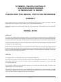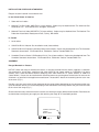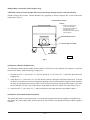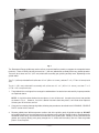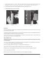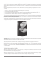
1
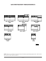
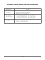
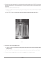
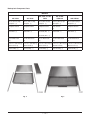
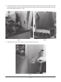
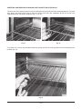
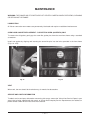
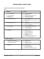
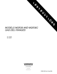
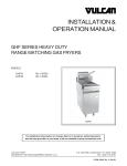
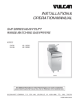
INSTALLATION &
OPERATION MANUAL
GAS RESTAURANT RANGES
90 SERIES AND VG SERIES
MODEL
24L
36L
48L
481L
148L
60L
160L
260L
VG24
VG36
VG48
VG60
VG160
VG260
ML-52947
ML-52948
ML-52949
ML-52950
ML-52951
ML-52952
ML-52953
ML-52954
ML-114553
ML-114554
ML-114957
ML-114555
ML-114556
ML-114557
MODEL 36L/VG36
VULCAN-HART
COMPANY,
FORM 31055 Rev. C (Mar. 2001)
P.O.
BOX
696,
LOUISVILLE,
KY
40201-0696,
TEL. (502) 7 7 8 - 2 7 9 1
IMPORTANT FOR YOUR SAFETY
THIS MANUAL HAS BEEN PREPARED FOR PERSONNEL QUALIFIED TO INSTALL GAS
EQUIPMENT, WHO SHOULD PERFORM THE INITIAL FIELD START-UP AND
ADJUSTMENTS OF THE EQUIPMENT COVERED BY THIS MANUAL.
POST IN A PROMINENT LOCATION THE INSTRUCTIONS TO BE FOLLOWED IN THE
EVENT THE SMELL OF GAS IS DETECTED. THIS INFORMATION CAN BE OBTAINED
FROM THE LOCAL GAS SUPPLIER.
IMPORTANT
IN THE EVENT A GAS ODOR IS DETECTED, SHUT
DOWN UNITS AT MAIN SHUTOFF VALVE AND
CONTACT THE LOCAL GAS COMPANY OR GAS
SUPPLIER FOR SERVICE.
FOR YOUR SAFETY
DO NOT STORE OR USE GASOLINE OR OTHER
FLAMMABLE VAPORS OR LIQUIDS IN THE
VICINITY OF THIS OR ANY OTHER APPLIANCE.
WARNING
IMPROPER INSTALLATION, ADJUSTMENT,
ALTERATION, SERVICE OR MAINTENANCE CAN
CAUSE PROPERTY DAMAGE, INJURY OR DEATH.
READ THE INSTALLATION, OPERATING AND
MAINTENANCE INSTRUCTIONS THOROUGHLY
BEFORE INSTALLING OR SERVICING THIS
EQUIPMENT.
IN THE EVENT OF A POWER FAILURE, DO NOT
ATTEMPT TO OPERATE THIS DEVICE.
—2—
TABLE OF CONTENTS
GAS RESTAURANT RANGE MODELS . . . . . . . . . . . . . . . . . . . . . . . . . . . . . . . . . . . . . . . . . . . . . . 4
OPTIONAL FIELD INSTALLABLE ACCESSORIES . . . . . . . . . . . . . . . . . . . . . . . . . . . . . . . . . . . . 5
GENERAL . . . . . . . . . . . . . . . . . . . . . . . . . . . . . . . . . . . . . . . . . . . . . . . . . . . . . . . . . . . . . . . . . . . . . 6
INSTALLATION . . . . . . . . . . . . . . . . . . . . . . . . . . . . . . . . . . . . . . . . . . . . . . . . . . . . . . . . . . . . . . . . . 6
Uncrating . . . . . . . . . . . . . . . . . . . . . . . . . . . . . . . . . . . . . . . . . . . . . . . . . . . . . . . . . . . . . . . . 6
Location . . . . . . . . . . . . . . . . . . . . . . . . . . . . . . . . . . . . . . . . . . . . . . . . . . . . . . . . . . . . . . . . . 6
Installation Codes and Standards . . . . . . . . . . . . . . . . . . . . . . . . . . . . . . . . . . . . . . . . . . . . . 7
Assembly . . . . . . . . . . . . . . . . . . . . . . . . . . . . . . . . . . . . . . . . . . . . . . . . . . . . . . . . . . . . . . . . 7
Ranges Mounted on Casters . . . . . . . . . . . . . . . . . . . . . . . . . . . . . . . . . . . . . . . . . . . 7
Bumper Bars (Convection Oven Ranges Only) . . . . . . . . . . . . . . . . . . . . . . . . . . . . 8
Installation of Broiler/Griddle Bricks . . . . . . . . . . . . . . . . . . . . . . . . . . . . . . . . . . . . . 8
Installation of Standard Griddle Top Bricks . . . . . . . . . . . . . . . . . . . . . . . . . . . . . . . 8
Installation of Hot Top Bricks . . . . . . . . . . . . . . . . . . . . . . . . . . . . . . . . . . . . . . . . . 11
Backsplash . . . . . . . . . . . . . . . . . . . . . . . . . . . . . . . . . . . . . . . . . . . . . . . . . . . . . . . . 11
Leveling . . . . . . . . . . . . . . . . . . . . . . . . . . . . . . . . . . . . . . . . . . . . . . . . . . . . . . . . . . . . . . . . 14
Gas Connections . . . . . . . . . . . . . . . . . . . . . . . . . . . . . . . . . . . . . . . . . . . . . . . . . . . . . . . . . 14
Testing the Gas Supply System . . . . . . . . . . . . . . . . . . . . . . . . . . . . . . . . . . . . . . . . . . . . . 15
Flue Connections . . . . . . . . . . . . . . . . . . . . . . . . . . . . . . . . . . . . . . . . . . . . . . . . . . . . . . . . . 16
Electrical Connections . . . . . . . . . . . . . . . . . . . . . . . . . . . . . . . . . . . . . . . . . . . . . . . . . . . . . 16
OPERATION . . . . . . . . . . . . . . . . . . . . . . . . . . . . . . . . . . . . . . . . . . . . . . . . . . . . . . . . . . . . . . . . . .
Controls . . . . . . . . . . . . . . . . . . . . . . . . . . . . . . . . . . . . . . . . . . . . . . . . . . . . . . . . . . . . . . . .
Before First Use . . . . . . . . . . . . . . . . . . . . . . . . . . . . . . . . . . . . . . . . . . . . . . . . . . . . . . . . . .
Lighting and Shutting Down Pilots . . . . . . . . . . . . . . . . . . . . . . . . . . . . . . . . . . . . . . . . . . .
Rack Arrangement - Standard Oven . . . . . . . . . . . . . . . . . . . . . . . . . . . . . . . . . . . . . . . . .
Rack Arrangement - Convection Oven . . . . . . . . . . . . . . . . . . . . . . . . . . . . . . . . . . . . . . . .
Inserting and Removing Standard and Convection Oven Racks . . . . . . . . . . . . . . . . . . .
Preheating . . . . . . . . . . . . . . . . . . . . . . . . . . . . . . . . . . . . . . . . . . . . . . . . . . . . . . . . . . . . . .
Loading and Unloading Standard and Convection Ovens . . . . . . . . . . . . . . . . . . . . . . . .
Cooking Chart . . . . . . . . . . . . . . . . . . . . . . . . . . . . . . . . . . . . . . . . . . . . . . . . . . . . . . . . . . .
Cleaning . . . . . . . . . . . . . . . . . . . . . . . . . . . . . . . . . . . . . . . . . . . . . . . . . . . . . . . . . . . . . . . .
17
17
17
17
22
22
23
24
24
25
28
MAINTENANCE . . . . . . . . . . . . . . . . . . . . . . . . . . . . . . . . . . . . . . . . . . . . . . . . . . . . . . . . . . . . . . . .
Lubrication . . . . . . . . . . . . . . . . . . . . . . . . . . . . . . . . . . . . . . . . . . . . . . . . . . . . . . . . . . . . . .
Oven Door Gasket Replacement - Convection Oven Only . . . . . . . . . . . . . . . . . . . . . . . .
Vent . . . . . . . . . . . . . . . . . . . . . . . . . . . . . . . . . . . . . . . . . . . . . . . . . . . . . . . . . . . . . . . . . . . .
Service and Parts Information . . . . . . . . . . . . . . . . . . . . . . . . . . . . . . . . . . . . . . . . . . . . . . .
31
31
31
31
31
TROUBLESHOOTING GUIDE . . . . . . . . . . . . . . . . . . . . . . . . . . . . . . . . . . . . . . . . . . . . . . . . . . . . 32
—3—
GAS RESTAURANT RANGE MODELS
60L, 60LC, 60LCC
VG60
48L/VG48
260L, 260LC, 260LCC
VG260
148L, 148LC
36L, 36LC
VG36
160L, 160LC
VG160
481L, 481LC
24L
VG24
PL-53007
NOTE: References to 90 Series Convection Ovens will include only the following models: 36LC, 148LC, 481LC,
60LC, 60LCC, 160LC, 260LC or 260LCC.
—4—
OPTIONAL FIELD INSTALLABLE ACCESSORIES
DESCRIPTION
OPTIONS
Flue Devices
1. Stainless steel backsplash with plate shelf.
2. Stainless steel 11" (27.9 cm) low riser.
Flex Hose and
Quick Disconnects
1.
2.
3.
Oven Racks
1. 1 extra rack – standard oven style.
2. 1 extra rack – convection oven style.
3
/4" (19 mm) flex hose/disconnect – 3 ft. (914.4 mm) long.
/4" (19 mm) flex hose/disconnect – 4 ft. (1219.2 mm) long.
3
/4" (19 mm) flex hose/disconnect – 5 ft. (1524 mm) long.
3
—5—
Installation, Operation and Care of
GAS RESTAURANT RANGES
90 SERIES AND VG SERIES
PLEASE KEEP THIS MANUAL FOR FUTURE REFERENCE
GENERAL
Vulcan ranges and ovens are produced with quality workmanship and material. Proper installation, usage and
maintenance of your range will result in many years of satisfactory performance.
Vulcan-Hart suggests that you thoroughly read this entire manual and carefully follow all of the instructions
provided.
INSTALLATION
UNCRATING
This range was inspected before leaving the factory. The transportation company assumes full responsibility for
safe delivery upon acceptance of the shipment. Immediately after unpacking, check for possible shipping damage.
If the range is found to be damaged, save the packaging material and contact the carrier within 15 days of delivery.
Uncrate unit carefully and place in a work-accessible area as near to its final installed position as possible. Remove
all shipping wire and wood blocking.
Before installing, check the electrical service (convection oven series ranges only) and type of gas supply (natural or
propane) to make sure they agree with the specifications on the rating plate located on the inside of the lower kick
panel. If the supply and equipment requirements do not agree, do not proceed with the installation. Contact your
dealer or Vulcan-Hart Company immediately.
LOCATION
The equipment area must be kept free and clear of combustible substances.
The range, when installed, must have a minimum clearance from combustible construction of 6" (152.4 mm) at the
sides and 6" (152.4 mm) at the rear. Clearance from non-combustible construction is 0" at the sides and
6" (152.4 mm) at the rear.
The installation location must allow adequate clearances for servicing and proper operation. A minimum front
clearance of 40" (101.6 cm) is required.
The range must be installed so that the flow of combustion and ventilation air will not be obstructed. Adequate
clearance for air openings into the combustion chamber must be provided. Make sure there is an adequate supply
of air in the room to allow for combustion of the gas at the burners.
—6—
INSTALLATION CODES AND STANDARDS
Ranges must be installed in accordance with:
In the United States of America
1. State and local codes.
2. National Fuel Gas Code, ANSI-Z223.1 (latest edition). Copies may be obtained from The American Gas
Association, Inc., 1515 Wilson Blvd., Arlington, VA 22209.
3. National Electrical Code ANSI/NFPA-70 (latest edition). Copies may be obtained from The National Fire
Protection Association, Batterymarch Park, Quincy, MA 02269.
In Canada
1. Local codes.
2. CAN/CGA-B149.1 Natural Gas Installation code (latest edition).
3. CAN/CGA-B149.2 Propane Installation Code (latest edition). Copies may be obtained from The Canadian
Standards Association, 178 Rexdale Blvd., Etobicoke, Ontario, Canada M9W 1R3.
4. Canadian Electrical Code, CSA Standard C22.2, Part 3 (latest edition). Copies may be obtained from The
Canadian Standards Association, 178 Rexdale Blvd., Etobicoke, Ontario, Canada M9W 1R3.
ASSEMBLY
Ranges Mounted on Casters
NOTICE: When the range is mounted on casters, it must be installed with the casters supplied, a connector
(not supplied by Vulcan-Hart) complying with either ANSI-Z21.69 (latest edition) or CAN/CGA-6.16 (latest
edition), and a quick-disconnect device complying with either ANSI-Z21.41 (latest edition) or CAN1-6.9
(latest edition). It must also be installed with restraining means to guard against transmission of strain to the
connector, as specified in the appliance manufacturer’s instructions. Attach the restraining device at the rear
of the oven (Fig. 1).
Provide a gas line strain relief to limit movement of the range without depending on the connector and/or any
quick-disconnect device or its associated piping to limit movement of the range. Attach the gas line strain relief
to the rear of the range (Fig. 1).
Should it be necessary to disconnect the restraint, turn off the gas supply before disconnection. Reconnect the
restraint before turning the gas supply on and returning the range to its installation position.
CONNECT GAS LINE
STRAIN
RELIEF HERE
PL-51219
Fig. 1
—7—
Bumper Bars (Convection Oven Ranges Only)
CAUTION: Failure to install bumper bars may cause motor damage and will void the warranty.
Remove existing #10 screws. Position bumper bars (supplied) as shown. Replace #10 screws and secure
bumper bars (Fig. 2).
REAR VIEW OF RANGE
NOTES:
1. Bumper bars required for all
Convection Oven Ranges.
2. Restraining device required for
all ranges with casters.
3. Restraining device not supplied by
unit manufacturer.
RESTRAINING DEVICE
#10 SHEET METAL SCREW
BUMPER BAR
PL-50109
Fig. 2
Installation of Broiler/Griddle Bricks
The Restaurant Range broiler/griddle utilizes ceramic fire bricks for heat radiation of the burners. Install the
broiler bricks before connecting the gas supply line.
1. Remove the six 51/4" (133.4 mm) x 21/4" (57 mm) and (6) 51/4" (133.4 mm) x 51/ 16" (128.6 mm) bricks from the
shipping box.
2. Install the six 51/4" (133.4 mm) x 21/ 4" (57 mm) bricks to the left- and right-hand sides of the burner. To install
the bricks, insert them one at a time through the opening in the front of the broiler. Angle the brick sideways
so that it will slip between the burner edges. Set the bricks flat in place resting on these edges. Push each
brick installed as far to the rear of the burner as possible so that the last brick will install easily (Fig. 3).
3. Install the six 51/4" (133.4 mm) x 51/16" (128.6 mm) bricks to the center burners as described in Step 2.
Installation of Standard Griddle Top Bricks
The griddle top section is extremely heavy. It will require three people to install the griddle and griddle brick —
two people to lift the griddle plate and one person to set the bricks and griddle thermostat capillary bulb(s)
in place.
—8—
Fig. 3
The Restaurant Range griddle top section utilizes a two-fold baffle assembly to support the composite/mortar
fire bricks. There will always be only one small 61/2" (165 mm) wide baffle assembly with every griddle top order.
There will be at least one 97/8" (251 mm) wide baffle assembly per griddle, possibly more, depending on the
griddle width.
The 61/ 2" (165 mm) wide baffle will utilize two 10" x 4" (254 x 101.6 mm), and two 7" x 4" (177.8 x 101.6 mm) brick
sets.
The 9 7 / 8 " (251 mm) wide baffle assembly will utilize two 10" x 4" (254 x 101.6 mm), and two 7" x 4"
(177.8 x 101.6 mm) brick sets.
1. The griddle bricks are shipped in a rectangular cardboard box. Locate the box and carefully inspect quantities
as explained above.
NOTE: If a brick has been broken into two pieces, it can still be used. Just place the pieces into position
as shown in Fig. 4. However, if a brick is broken into more than two pieces, it will need to be replaced.
Contact your local Vulcan servicer.
2. Clean anti-rust coating from top of griddle, following the procedures described in the CLEANING - GRIDDLE
PLATE section of this manual.
3. Remove griddle plate. With one person at either side of the griddle, gently lift griddle straight up. DO NOT
pull griddle forward until the third person has checked to ensure that the capillary bulb(s) (thermostatically
controlled models only) are freed from the underside of the griddle plate. If bulb(s) are still attached to the
griddle, pull capillary bulb(s) wire gently through the “V” shields until the bulb(s) are free. Rest the griddle
plate in a secure place.
—9—
4. Exercise caution when placing brick in a thermostatically controlled griddle section. DO NOT hit thermostat
bulb while installing bricks. The thermostat bulb is a sensitive device and may be easily knocked out of
adjustment.
Into the 61/2" (165 mm) wide baffle, install:
a. Two 10" x 4" (254 x 101.6 mm) bricks, placing the miter edge, one to each side of the front burner baffle
area (Fig. 4).
b. Two 7" x 4" (177.8 x 101.6 mm) bricks, one to each side of the rear burner baffle area (Fig. 4).
Fig. 4
5. Into the 97/8" (251 mm) wide baffle, install:
a. Two 10" x 4" (254 x 101.6 mm) bricks, placing the miter edge, one to each side of the front burner baffle
area (see Fig. 4).
b. Two 7" x 4" (177.8 x 101.6 mm) bricks, one to each side of the rear burner baffle area (see Fig. 4).
6. If burner has been strapped down, remove the wire strapping device, using wire cutters.
— 10 —
7. Check to ensure that all bricks and burners are secure. Carefully replace the griddle top section. When
replacing griddle top section, be sure that the griddle capillary and bulb(s) are not in a position to be crushed.
Gently pull the griddle capillary towards the front of the range and out from under the griddle area. While two
people (one on each side of the griddle) are lowering the griddle into place, the third person must gently feed
the griddle thermostat bulb(s) through the “V” shield(s) until completely covered. Also ensure that the
capillary is not positioned over the burner flame pattern. Continue to lower the plate into place until it is resting
evenly on top of the range.
Installation of Hot Top Bricks
The Restaurant Range hot top sections utilize composite/mortar fire bricks for heat distribution of the burners.
Install these bricks before connecting the gas supply line or installing the back riser.
1. The composite/mortar bricks are shipped in a rectangular cardboard box. Locate box and carefully remove
two 10" x 4" (254 x 101.6 mm), and two 7" x 4" (177.8 x 101.6 mm) bricks. There should be one box of bricks
per hot top section ordered.
NOTE: If a brick has been broken into two pieces, it can still be used. Just place the pieces into position
as shown in Fig. 4. However, if a brick is broken into more than two pieces, it will need to be replaced.
Contact your local Vulcan servicer.
2. Rest the hot top plate in a secure area.
3. Install two 10" x 4" (254 x 101.6 mm) composite/mortar bricks, placing the miter edge, one to each side of the
front burner baffle area (see Fig. 4).
4. Install two 7" x 4" (177.8 x 101.6 mm) bricks, one to each side of rear burner baffle area (see Fig. 4).
5. If burner has been strapped down, remove the wire strapping device, using wire cutters.
6. Check to ensure that all bricks and the burner are secure. Carefully replace the hot top section on top of the
range.
Backsplash
The standard Restaurant Range is equipped with a 23" (58.4 cm) high backsplash and shelf.
1. Remove the backsplash components from the crating materials.
2. Check the backsplash component parts against the list on page 12 to ensure that all the required parts for
the backsplash installation have been obtained. (See Fig’s. 5 & 6.) If any parts are missing, contact your
dealer or closest parts depot immediately.
3. Assemble the required components as shown in Fig’s. 5 and 6.
4. Lift the assembly up, sliding the channels into the space provided at the rear of the range (this may require
two people).
— 11 —
Backsplash Component Parts
MODELS
24L/VG24
36L/VG36
48L, 481L, & 148L
VG48
60L & 160L
VG60/160
260L/VG260
Std. 23" (58.4 cm) High
Backsplash (1)
Std. 23" (58.4 cm) High
Backsplash (1)
Std. 23" (58.4 cm) High
Backsplash (1)
Std. 23" (58.4 cm) High
Backsplash (1)
Std. 23" (58.4 cm) High
Backsplash (1)
Backsplash Channel
(2)
Backsplash Channel
(2)
Backsplash Channel
(2)
Riser Channel
(1)
Backsplash Channel
(2)
Heat Shield (1)
Heat Shield (1)
Heat Shield (48L) (1)
Heat Shield (1)
Heat Shield (1)
#10 Sht. Metal Screw
(20)
#10 Sht. Metal Screw
(4)
Heat Shield (481L) (1)
#10 Sht.Metal Screw
(16)
#10 Sht. Metal Screw
(16)
#10 Sht. Metal Screw
(16)
1
/4-20 x 25/16" (58.7 mm) Lg. 1/4-20 x 25/16" (58.7 mm) Lg. 1/4-20 x 25/16" (58.7 mm) Lg. 1/4-20 x 25/16" (58.7 mm) Lg. 1/4-20 x 25/16" (58.7 mm) Lg.
Machine Screw (4)
Machine Screw (4)
Machine Screw (4)
Machine Screw (4)
Machine Screw (6)
Shelf Assembly (1)
Shelf Assembly (1)
Shelf Assembly (1)
Fig. 5
Shelf Assembly (1)
Fig. 6
— 12 —
Shelf Assembly (1)
5. It may be necessary to pull the heat shield bottom out slightly in order to clear the oven flue box area. Be
sure the backsplash is resting evenly and the channel holes are lining up with the holes provided in the rightand left-hand body side (Fig’s. 7 & 8).
Fig. 7
Fig. 8
6. Install eight #10 sheet metal screws (4 to each channel leg) (Fig. 9).
Fig. 9
— 13 —
7. From the front, install four 1/4-20 x 25/16" (58.7 mm) long machine screws and secure bolts with locknuts. Do
not tighten the screws all the way down. Leave about 1/4" (6.3 mm) of play in each screw (Fig. 10).
8. Lift the shelf up and slide the shelf into position over the screw heads (Fig. 11).
9. Tighten the four screws to secure the shelf.
Fig. 10
Fig. 11
LEVELING
Check the leveling of the range. Place a carpenter’s level inside the oven cavity across the oven rack(s). Level
front-to-back and side-to-side.
To adjust the leveling, tilt the range to one side and, using channel locks, unscrew the adjustable leg insert as
required. Repeat this procedure as necessary for each leg.
Casters for this range are of the non-adjustable type. Therefore, the floor must be level. If floor surface is not
level, the range will experience cooking problems.
GAS CONNECTIONS
CAUTION: All gas supply connections and any pipe joint compound used must be resistant to the action
of propane gases.
Each range is factory-equipped for the type gas specified on the rating plate. The installation gas connection is
a 3/4" (19 mm) 14 FPT ANSI schedule #40 standard pipe.
Connect gas supply. Make sure the pipes are clean and free of obstructions.
Codes require that a gas shutoff valve be installed in the gas line ahead of the range.
Standard ranges are equipped with fixed burner orifices which coincide with installation elevation.
Install the gas pressure regulator.
Before installing, ensure that regulator supplied agrees with rating plate gas supply.
— 14 —
As of 7/11/90, the gas pressure regulator is NOT factory installed. The regulator for this gas type is sealed within
a plastic bag attached to the oven rack inside the oven cavity. This regulator must be field installed by a qualified
installer.
Natural gas regulators are preset for 3.7" W.C. (Water Column) (.92 kPa); propane gas regulators for 10.0" W.C.
(2.5 kPa)
1.
2.
3.
4.
Locate 3/4" (19 mm) gas connection pipe extending from rear of range.
Cover pipe threads with leak sealant.
Screw regulator hand-tight onto pipe with regulator arrow pointing towards range body back (Fig. 12).
Using pipe wrench, tighten regulator securely in an upright position (Fig. 12).
The arrow on the regulator shows the direction of the gas flow (Fig. 12). The pressure regulator must be mounted
horizontally to ensure proper preset outlet pressure. If the regulator is installed in any other position, the outlet
pressure must be reset for proper operation.
A leak limiter is supplied with every regulator to allow excess gas pressure to escape. Do not obstruct leak limiter
on gas pressure regulator, as obstruction may cause regulator to malfunction.
Fig. 12
WARNING: PRIOR TO LIGHTING, CHECK ALL JOINTS IN THE GAS SUPPLY LINE FOR LEAKS. USE SOAP
AND WATER SOLUTION. DO NOT USE AN OPEN FLAME.
After piping has been checked for leaks, all piping receiving gas should be fully purged to remove air.
Before operation, verify thermocouple is securely seated in the safety valve. The thermocouple should be
tightened a 1/4 turn past finger tight. DO NOT OVERTIGHTEN. Overtightening may damage the thermocouple
or safety magnet.
TESTING THE GAS SUPPLY SYSTEM
When gas supply pressure exceeds 1/2 psig (3.45 kPa), the range and its individual shutoff valve must be
disconnected from the gas supply piping system.
When gas supply pressure is 1/2 psig (3.45 kPa) or less, the range should be isolated from the gas supply
system by closing its individual manual shutoff valve until the range is ready for start-up.
— 15 —
FLUE CONNECTIONS
DO NOT obstruct the flow of flue gases from the flue located on the rear of the range. It is recommended that
the flue gases be ventilated to the outside of the building through a ventilation system installed by qualified
personnel.
From the termination of the flue to the filters of the hood venting system, a minimum clearance of 18" (457 mm)
must be maintained.
Information on the construction and installation of ventilating hoods may be obtained from the standard for the
"Removal of Vapors from Commercial Cooking Equipment”, NFPA No. 96 (latest edition), available from The
National Fire Protection Association, Batterymarch Park, Quincy, MA 02269.
ELECTRICAL CONNECTIONS (CONVECTION OVEN MODELS [90 SERIES] ONLY)
WARNING: ELECTRICAL AND GROUNDING CONNECTIONS MUST COMPLY WITH THE APPLICABLE
PORTIONS OF THE NATIONAL ELECTRICAL CODE AND/OR OTHER LOCAL ELECTRICAL CODES.
WARNING: DISCONNECT ELECTRICAL POWER SUPPLY AND PLACE A TAG AT THE DISCONNECT
SWITCH TO INDICATE YOU ARE WORKING ON THE CIRCUIT.
WARNING: APPLIANCES EQUIPPED WITH A FLEXIBLE ELECTRIC SUPPLY CORD ARE PROVIDED WITH
A THREE-PRONG GROUNDING PLUG. IT IS IMPERATIVE THAT THIS PLUG BE CONNECTED INTO A
PROPERLY GROUNDED THREE-PRONG RECEPTACLE. IF THE RECEPTACLE IS NOT THE PROPER
GROUNDING TYPE, CONTACT AN ELECTRICIAN. DO NOT REMOVE THE GROUNDING PRONG FROM
THIS PLUG.
The range is designed for 120 volt power supply or an optional 240 volt single-phase 15 Amp power supply.
All 120 volt ranges are supplied with a flexible electric supply cord and plug and must be plugged into the proper
receptacle before turning on gas. If the appliance is not equipped with a grounding plug and electric supply is
needed, ground the appliance by using the ground lug provided. All 240 volt electric systems are manufactured
for hard wire installation connections. (Refer to the wiring diagram inserted into this manual.) An electrical
diagram is attached to the back near the motor mounting area.
Do not connect the range to electrical supply until after gas connections have been made.
— 16 —
OPERATION
WARNING: THE RANGE AND ITS PARTS ARE HOT. BE VERY CAREFUL WHEN OPERATING, CLEANING
OR SERVICING THE RANGE.
CONTROLS
THERMOSTAT DIAL - STANDARD OVEN
— Allows operator to regulate oven temperature from low to
500°F (260°C).
THERMOSTAT DIAL - CONVECTION OVEN — Snap-acting type control which allows operator to regulate
oven temperature from 150°F to 500°F (65.5°C to 260°C).
OPEN TOP BURNER KNOB STANDARD AND CONVECTION OVENS
— Regulates gas flow to top burners. To increase heat, turn
knob counterclockwise; to decrease, turn knob clockwise.
POWER SWITCH - CONVECTION OVEN
—
HEATING LIGHT - CONVECTION OVEN
— When lit, indicates that the oven thermostat is calling for
heat to the oven.
GRIDDLE BURNER KNOB STANDARD AND CONVECTION OVENS
ON-OFF switch controls power supply to convection oven
control.
— Regulates gas flow to the griddle or hot top burner. To
increase heat, turn knob counterclockwise; to decrease,
turn knob clockwise.
BEFORE FIRST USE
Griddle Seasoning
CAUTION: This griddle plate is steel, but the surface is relatively soft and can be scored or dented by the
careless use of a spatula or scraper. Be careful not to dent, scratch, or gouge the plate surface. Do not
try to knock off loose food that may be on the spatula by tapping the corner edge of the spatula on the
griddle surface.
A new griddle surface must be seasoned to do a good cooking job. The metal surface of the griddle is porous.
Food tends to get trapped in these pores and stick; therefore, it is important to “season” or “fill up” these pores
with cooking oil before cooking. Seasoning gives the surface a slick, hard finish from which the food will release
easily.
To season, heat griddle top section at a low burner setting. Pour one ounce of cooking oil per square foot of
surface over the griddle top section. With an insulated cloth, spread the oil over the entire griddle surface to
create a thin film. Wipe off any excess oil with an insulated cloth.
Repeat this procedure 2 to 3 times until the griddle has a slick surface.
LIGHTING AND SHUTTING DOWN PILOTS
All adjustment procedures associated with pilot lighting must be performed by an authorized Vulcan-Hart
installation or service person.
— 17 —
Hot Top and Griddle Top Burners
1. Turn main gas supply ON.
2. Wait 30 seconds and, using a taper, light the hot top or griddle top pilot (Fig. 13).
Shown with old style burner knobs
New style burner knobs effective 1/98
Fig. 13
3. If pilot fails to light, turn main gas supply OFF. Wait 5 minutes and repeat the above procedures.
4. Turn one hot top or griddle top burner valve ON to remove air from the gas line. Turn burner valve OFF when
gas begins to flow.
Nightly Shutdown: Turn burner valve OFF; pilot will remain lit.
Complete Shutdown
1. Turn burner valve OFF; pilot will remain lit.
2. Turn main gas supply OFF.
Open Top Burners
1. Turn main gas supply ON.
2. Wait 30 seconds and, using a taper, light the open top pilot (Fig. 14).
Fig. 14
— 18 —
3. If pilot fails to light, turn main gas supply OFF. Wait 5 minutes and repeat the above procedures.
4. Turn one open top burner valve ON to remove air from the gas line. Turn burner OFF when gas begins to
flow.
Nightly Shutdown: Turn burner valve OFF; pilot will remain lit.
Complete Shutdown
1. Turn burner valve OFF; pilot will remain lit.
2. Turn main gas supply OFF.
Broiler/Griddle
1. Turn main gas supply ON.
2
Wait 30 seconds and, using a taper, light broiler/griddle pilot (see Fig. 13).
3. If pilot fails to light, turn main gas supply OFF. Wait 5 minutes and repeat Steps 1 and 2.
4. Turn burner valve ON to purge air from the lines. Turn burner valve OFF when gas begins to flow.
Nightly Shutdown: Turn burner valve OFF; pilot will remain lit.
Complete Shutdown
1. Turn burner valve OFF; pilot will remain lit.
2. Turn main gas supply OFF.
Standard Oven
Light open top/griddle pilots before lighting oven pilot.
1. Open kick panel and lift up the pilot lighting hole cover (Fig. 15).
Fig. 15
Fig. 16
2. Light pilot by depressing the reset button located behind the kick panel (Fig. 16). Continue to hold reset button
in for 1 minute. If pilot fails to light, turn main gas supply OFF and wait 5 minutes before repeating Step 2.
— 19 —
3. After pilot is lit, turn the thermostat to the desired setting.
Nightly Shutdown: Turn oven thermostat OFF.
Complete Shutdown
1. Turn oven thermostat OFF.
2. Turn main gas supply OFF.
Standard Oven with Spark Ignition (Fig. 17)
1. Move toggle switch to ON position. Oven On Light will illuminate. The oven pilot will automatically light.
2. Once the oven pilot is established, the oven READY light will illuminate.
3. Set oven thermostat to desired temperature.
Nightly Shutdown: Push toggle switch to OFF position.
Complete Shutdown
1. Push toggle switch to OFF position.
2. Turn main gas supply OFF.
THERMOSTAT
OVEN "ON"
LIGHT
TOGGLE
SWITCH
OVEN "READY"
LIGHT
PL-53531
Fig. 17
Convection (Snorkel®) Oven (90 Series Only)
Light open top/griddle pilots before lighting oven pilot.
1. Open the kick panel and lift up the pilot lighting hole cover (see Fig. 15).
2. Turn red gas valve ON (located behind the kick panel), purging the gas line of all air (Fig. 18). Turn gas valve
and power switch OFF. Close oven door.
3. Light oven pilot by depressing the reset button (Fig. 19) and, using a taper, ignite the pilot. Hold reset button
in for 30 seconds or until pilot remains lit. Turn gas valve ON.
— 20 —
4. If pilot fails to light, turn main gas supply OFF. Wait 5 minutes and repeat Steps 2 and 3.
5. After pilot is lit, push the power switch ON and turn the thermostat to the desired setting.
Nightly Shutdown: Turn the power switch OFF and the thermostat to 0 degrees.
Complete Shutdown
1.
2.
3.
4.
Push power switch OFF.
Turn red gas valve OFF (behind kick panel).
Turn main gas supply OFF.
Disconnect electrical supply cord.
Fig. 18
Fig. 19
Convection (Snorkel®) Oven With Spark Ignition (Fig. 20)
THERMOSTAT
KNOB
TOP SECTION
BURNER KNOB
OVEN "ON"
LIGHT
ROCKER
SWITCH
THERMOSTAT
LIGHT
OVEN READY
LIGHT
Fig. 20
— 21 —
PL-53530
1. Move rocker switch to ON position (oven ON light will illuminate). The oven pilot will automatically light.
2. Once the oven pilot is established, the oven READY light will illuminate.
3. Set oven thermostat to desired temperature. (The thermostat light will illuminate. This indicates that the
thermostat is calling for heat.)
The convection oven thermostat must be ON and calling for heat for the oven pilot to light.
Nightly Shutdown: Push rocker switch and turn all knobs to the OFF position.
Complete Shutdown
1. Push rocker switch and turn all knobs to the OFF position.
2. Turn main gas supply OFF.
RACK ARRANGEMENT - STANDARD OVEN
The standard oven has two rack positions and is supplied with one oven rack. Additional racks may be obtained
through a Vulcan-Hart parts depot.
For best results when baking cakes and pastries, it is recommended that only a single rack position be utilized.
However, proper rack usage and positioning is really determined by the individual cooking needs of the operator.
If you are cooking a large roast, the entire oven cavity may be utilized. Remove the oven rack completely from
the range and place the roasting pan directly on the oven bottom.
RACK ARRANGEMENT - CONVECTION OVEN (90 SERIES ONLY)
The convection (Snorkel®) oven is supplied with three oven racks (maximum capacity). The oven cavity provides
a 5-position rack support for maximum cooking flexibility. The arrangements described below are the most
commonly recommended. The rack positions are numerically sequenced starting at the bottom.
Arrangement #1
Three racks in Positions 1, 3, and 5 for oven broiling, baking cookies, or reconstitution of frozen meals. This is
also the recommended position arrangement for general baking in sheet pans with products not over
21/2" (63.5 mm) high.
Arrangement #2
Two racks in Positions 2 and 4 for general baking in sheet pans, muffin pans, pie or cake tins and pudding pans
31/2" (88.9 mm) high with products not over 4" (101.6 mm) high. This arrangement may also be used for
casseroles or meat dishes in #200 series food service pans 12" x 20" x 21/2" (304.8 x 508 x 63.5 mm).
Arrangement #3
Two racks in Positions 1 and 4 for baking breads or cakes in loaf or tube pans and high meringue pies. This
arrangement may also be used for casseroles, meat dishes or roasting in pans up to 41/2" (114.3 mm) deep with
products up to 5" (127 mm) high.
When mix loading of food products is a regular kitchen practice, some operators have developed other rack
position arrangements to suit their particular needs.
— 22 —
INSERTING AND REMOVING STANDARD AND CONVECTION OVEN RACKS
The oven rack has a stop to keep the rack from being pulled all the way out when unloading product. To install
rack, place rack along side of top of side liner runners and slide rack completely to the rear of the oven
compartment until rack drops into place (Fig’s. 21 & 22).
Fig. 21
Fig. 22
To remove rack, reverse the procedure above by raising rear of oven rack stop above runner and pulling rack
forward (Fig. 23).
Fig. 23
— 23 —
PREHEATING
Standard Oven
Turn thermostat control to the desired cooking temperature and preheat oven for 25 minutes. To save on gas
consumption, do not operate oven at maximum heat when it is not necessary. Turn thermostat down to 250°F
(121°C) or OFF when oven is not in use or during idle cooking periods.
Convection Oven (90 Series Only)
With power switch in the ON position, turn oven thermostat knob to the proper cooking temperature and allow
oven to preheat for 15 minutes. To save on gas and electrical consumption, turn thermostat to one-half the
cooking temperature or completely OFF during idle cooking periods.
Hot Top Burners
Turn burner ON to highest heat to heat hot top section quickly. Hot top will be ready to cook on in about 10
minutes. After top section has reached operation temperature, turn some of the burners down. You will save as
much as 80% of gas consumption and notice very little difference in cooking performance as long as you have
allowed the entire hot top section to preheat properly.
Open Top Burners
Open top burners ignite quickly and do not require any preheating time. When food comes to a rolling boil, cut
back to slower boil to conserve energy, yet continue boiling. Turn burners ON only when in use.
Broiler/Griddle
Turn the three manual gas valve knobs to full ON. After preheating for 5 minutes, turn valves down until desired
flame or heating level is achieved. Position the removable broiler grid into one of the two slide positions,
depending on which will achieve the proper product results.
LOADING AND UNLOADING STANDARD AND CONVECTION OVENS
WARNING: WHEN USING CONVECTION OVENS, DO NOT STAND DIRECTLY IN FRONT OF THE OVEN
WHILE OPENING THE OVEN DOOR. ALTHOUGH OPENING THE OVEN DOOR WILL AUTOMATICALLY
SHUT THE FAN OFF, SOME HEAT ESCAPES. STEP AWAY TO AVOID HOT AIR.
Open the door and load as quickly as practical to conserve heat. Take care to avoid spilling liquids while loading.
Close the door and refer to recipe for cooking time.
Provide adequate space for product unloading. Rapid unloading will conserve heat and reduce preheating for
the next load.
— 24 —
COOKING CHART
Recommended temperatures and times are intended as a guide only. Adjustments must be made to compensate
for elevation, variations in recipes, ingredients, preparation and personal preference on product appearance.
Meat roasting is most satisfactory at temperatures of 225°F to 325°F (107°C to 162.7°C) for beef, lamb, poultry and
ham, and 325°F (162.7°C) for fresh pork as recommended by USDA and American Meat Institute.
A pan, approximately 12" x 20" x 1" (304.8 x 508 x 25.4 mm), full of water may be placed in the oven bottom to
supply humidity; this will reduce shrinkage. Water should be added if necessary during roasting.
Roasting pans should be no deeper than necessary to hold drippings, usually 2" to 21/2" (50.8 to 63.5 mm).
Cooking time and shrinkage may vary with roasting temperature, cut, grade of meat and degree of doneness.
Smaller cuts will generally show greater time savings than larger cuts at a given temperature.
ROASTING TEMPERATURES AND TIMES
PRODUCT
TEMPERATURE
APPROXIMATE TIME
Standing Rib Roast
Oven Ready - 15 lbs. (6.8 kg)
250°F/121°C
3-4 Hrs. - Rare
4-41/2 Hrs. - Med.
Rolled Rib Roast - 20-22 lbs. (9.1-10 kg)
275°F/135°C
4 Hrs. - Med.
Veal Roast - 15 lbs. (6.8 kg)
300°F/148.9°C
3 Hrs. - Med. Well
Turkey - 15-20 lbs. (6.8-9.1 kg)
300°F/148.9°C
3 Hrs.
Meat Loaf - 8-10 lbs. (3.6-4.5 kg)
350°F/176.7°C
45 to 60 Min.
RECOMMENDED TEMPERATURES, TIMES AND LOADS FOR BAKING
TEMPERATURE
APPROXIMATE
TIME
(MIN.)
Sheet Cakes - 18 x 26 x 1" (457 x 661 x 25.4 mm) pan
300 to 325°F/148.9 to 162.8°C
18 to 25
Scaled 41/2 to 6 lbs. (2 to 2.7 kg) per pan
Scaled 6 to 71/2 lbs. (2.7 to 3.4 kg) per pan
325 to 360°F/162.8 to 182°C
335 to 350°F/168.3 to 176.7°C
20 to 23
22 to 25
PRODUCT
Cakes
Sheet Cakes - 18 x 26 x 2" (457 x 661 x 50.8 mm) pan
Equals 2-12 x 18 x 2" (304.8 x 661 x 50.8 mm) pans
300 to 325°F/148.9 to 162.8°C
Scaled 10-12 lbs. (4.5-5.4 kg) per
18 x 26 x 2" (457 x 661 x 50.8 mm) pan or
5-6 lbs. (2.3-2.7 kg) per 12 x 18 x 2" (305 x 457 x 50.8 mm)
— 25 —
25 to 35
TEMPERATURE
APPROXIMATE TIME
(MIN.)
300 to 325°F/148.9 to 162.8°C
15 to 20
315 to 340°F/157.2 to 171°C
20 to 30
Cup Cakes
350 to 400°F/176.7 to 204.4°C
6 to 12
Frozen Fruit Pies
350 to 375°F/176.7 to 190.5°C
30 to 45
Pumpkin or Custard Pies
300 to 350°F/148.9 to 176.7°C
30 to 45
Cobblers
12 x 18 x 2" or 12 x 20 x 21/2" pans
(304.8 x 661 x 50.8 mm or 304.8 x 508 x 63.5 mm)
350 to 400°F/176.7 to 204.4°C
30 to 45
Meringue Pies
350 to 425°F/176.7 to 218.3°C
6 to 10
Fruit Turnovers
Sheet pans
350 to 375°F/176.7 to 190.5°C
15 to 25
PRODUCT
Angel or Sponge Cakes
Sheet pans 18 x 26 x 1" (457 x 661 x 25.4 mm)
Scaled 5-6 lbs. (2.3-2.7 kg) per pan
Loaf or Tube Pans
NOTE: Cobblers, fruit, custard and pumpkin pies should be placed on sheet pans for baking.
Cookies
Rolled or Pressed
Drop
350 to 400°F /176.7 to 204.4°C
350 to 400°F/176.7 to 204.4°C
6 to 12
6 to 15
350°F/176.7°C
12 to 20
Rolls - 1 oz. (.28 grams)
11/2 to 21/2 oz. (42.5 to 70.8 grams)
350 to 400°F/176.7 to 204.4°C
350 to 400°F/176.7 to 204.4°C
5 to 10
8 to 15
Loaf Bread - 1 lb. (0.5 kg)
325 to 375°F/162.8 to 190.5°C
20 to 40
Sweet Rolls and Pastries
325 to 375°F/162.8 to 190.5°C
5 to 15
Biscuits - Rolled 1/2" (12.7 mm) thick
350 to 400°F/176.7 to 204.4°C
5 to 15
Muffins
325 to 375°F/162.8 to 190.5°C
6 to 18
Corn Bread
18 x 26 x 1" (457 x 661 x 25.4 mm) pan,
5-7 lbs. (2.3-3 kg) per pan
18 x 26 x 2" (457 x 661 x 50.8 mm) pan,
8-20 lbs. (3.6-9.1 kg) per pan
335 to 400°F/168.3 to 204.4°C
10 to 20
335 to 400°F/168.3 to 204.4°C
15 to 25
335 to 385°F/168.3 to 196°C
10 to 20
Brownies
Yeast Breads
NOTE: Yeast breads should be fully proofed for best results.
Corn Muffins
— 26 —
OVEN BROILING OR FRYING
TEMPERATURE
APPROXIMATE TIME
(MIN.)
Hamburger Patties
8 per lb. (0.5 kg) - Med. well done
6 per lb. (0.5 kg)
4 per lb. (0.5 kg)
400 to 450°F/204.4 to 232.2°C
400 to 450°F/204.4 to 232.2°C
375 to 385°F/190.5 to 196°C
5 to 6
7 to 10
8 to 12
Fish Sticks & Portions
Frozen bread. - 1 oz. (28.3 grams)
21⁄2 to 3 oz. (70.8 to 85 grams)
350 to 400°F/176.7 to 204.4°C
350 to 375°F/176.7 to 190.5°C
6 to 10
8 to 15
Chicken Pieces
Broiled or Oven Fried
2 to 21⁄2 lbs. (0.9 to 1.1 kg)
21⁄2 to 3 lbs. (1.1 to 1.4 kg)
375 to 425°F/190.5 to 218.3°C
350 to 400°F/176.7 to 204.4°C
8 to 15
15 to 25
Lobsters
1 to 11⁄2 lbs. (0.5 to 0.6 kg)
400 to 450°F/204.4 to 232.2°C
12 to 16
Lobster Tails
Frozen, 1⁄2 to 1 lb. (0.2 to 0.5 kg)
350 to 400°F/176.7 to 204.4°C
16 to 20
Frozen French Fries
400 to 450°F/204.4 to 232.2°C
6 to 8
Frozen TV Dinners
350 to 400°F/176.7 to 204.4°C
10 to 12
Frozen Entrees - 1" (25.4 mm) thick
300 to 350°F/148.9 to 176.7°C
10 to 20
Frozen Meals
8 oz. (0.2 kg) foil package
350 to 400°F/176.7 to 204.4°C
20 to 30
Food Service Pans
2" to 3" (50.8 to 76.2 mm) deep
3" to 4" (76.2 to 101.6 mm) deep
325 to 375°F/162.8 to 190.5°C
325 to 375°F/162.8 to 190.5°C
15 to 25
20 to 35
Ramekins or Foil Pans
Up to 11⁄2" (38 mm) Deep
Frozen
350 to 400°F/176.7 to 204.4°C
350 to 400°F/176.7 to 204.4°C
5 to 6
10 to 15
PRODUCT
REHEATING PREPARED FOODS
CASSEROLES
— 27 —
MISCELLANEOUS PRODUCTS
TEMPERATURE
APPROXIMATE TIME
(MIN.)
400 to 450°F/204.4 to 232.2°C
400 to 450°F/204.4 to 232.2°C
400 to 450°F/204.4 to 232.2°C
25 to 35
35 to 45
40 to 60
425 to 475°F/218.3 to 246°C
5 to 10
400 to 425°F/204.4 to 218.3°C
8 to 10
PRODUCT
Baked Potatoes
120 count per 50 lbs (22.7 kg)
100 count per 50 lbs. (22.7 kg)
80 count per 50 lbs. (22.7 kg)
Pizzas
Frozen or with prebaked
crust
Grilled Cheese Sandwiches
SPECIAL BAKING PROCEDURES
YEAST BREADS: Cooking starts immediately in the convection oven. Yeast breads do not usually rise as much
in the convection oven as in a conventional oven. Therefore, it is necessary to allow 21/ 2 to 3 times longer for the
dough to reach its proofing capacities.
PIES: When baking pies in your convection oven, 3 or 4 pies should be put on an 18 x 26" (457 x 661 mm) sheet
or bun pan. This procedure helps the bottom crust to bake, makes handling easier and reduces the possibility
of boil-over, spoiling the appearance of the pies on the lower racks.
CLEANING
Do not use Dawn® dish detergent to clean the exterior or interior components of the range.
Do not use scouring powder. It is extremely difficult to remove completely. It can build up accumulations that will
damage the oven.
Vulcan painted surfaces may be cleaned using a soft cloth and mild detergent solution.
RANGES
Daily:
Remove nickel-plated racks and clean in a sink.
While still warm, wipe top with a soft cloth or other grease absorbing material to remove spillovers, grease, etc.,
before they burn in. A crust on top of the hot top range looks unsightly and slows down cooking speed because
it reduces the flow of heat to the utensil.
— 28 —
Clean oven and oven door daily, especially if fruit pies or tomato sauces were baked, meats roasted, and if there
have been spillovers.
After processing some foods at low temperatures, odors may linger in the oven. These odors may be cleared
by setting the thermostat at 500°F (260°C) and allowing the oven to operate unloaded for 30 to 45 minutes.
Empty the broiler grease pan/trough daily or as often as necessary. CAUTION: Remove the grease pan/trough
slowly and be careful of liquid wave action. It is recommended that the grease pan/trough be emptied
whenever it is 3/4 filled. The drip shield, grids and grease pan/trough should be washed with a mild greasedissolving solution. Some chefs scrape the grid with a three-cornered metal scraper. Scrub the broiler chamber
and body front frequently and you will have less smoking.
Clean cast iron open top grates with a mild soap and water solution. Rinse thoroughly and dry with a clean, waterabsorbent towel. Immediately after drying (with grates still removed from the range top), season grates lightly
with liquid vegetable or Pam spray-type cooking oil.
After seasoning, replace grates onto the range. Turn all open top sections ON LOW and allow them to burn for
at least 15 minutes before using pots or pans on the range top.
Season the open top grates after each cleaning. Failure to season grates will cause grates to rust.
Weekly:
Boil burners in a solution of washing soda. Rinse and dry parts thoroughly. Flash rusting may occur. This is a
normal condition and will not affect the performance or the product prepared.
When reinstalling the burner back onto the range, be sure the burner heads are properly connected. Do not light
the pilot or turn burner valve ON with the burner head removed.
CONVECTION OVENS (90 SERIES) ONLY
The Snorkel tube opening must be kept clear from blockage. If usage of aluminum foil is a common practice
during the operation of this oven, be sure to periodically check the Snorkel tube for foil particles. Clean this tube
with standard oven cleaner at least once a week. Be sure to thoroughly clean all cleansing solution off the tube
before using oven again. It is also recommended that the oven be run at 400°F (204°C) for 20 minutes to burn
off any cleaning solution that was not thoroughly rinsed from the tube.
Oven Door Gasket: (90 Series Connection Ovens Only)
To clean the oven door gasket, use a soft cloth or sponge and a mild cleanser. DO NOT USE STRONG OVEN
CLEANERS SUCH AS EASY OFF® OR MR. MUSCLE®. Cleaners of this nature will destroy the gasket material.
GRIDDLE PLATE
Cleaning the griddle section will produce evenly cooked, perfectly browned griddle products and will keep the
cooking surface free from carbonized grease. Carbonized grease on the surface hinders the transfer of heat to
the food. This results in loss of cooking efficiency and spotty browning which gives foods an unappetizing
appearance. To keep the griddle clean and operating at peak efficiency, follow these simple instructions:
After Each Use:
Carefully clean griddle with wire brush or flexible spatula.
— 29 —
Daily:
Thoroughly clean backsplash, sides and front. Remove grease pan, empty and wash out in the same manner
as any ordinary cooking utensil.
Clean griddle surface thoroughly. If necessary, use a griddle stone, wire brush or steel wool over the surface.
Rub with the grain of the metal while still warm. A detergent may be used on the plate surface to help clean it,
but the cleaner must be thoroughly removed. After removal of detergent, the surface of the plate must be
reseasoned with a thin film of oil to prevent rusting and food sticking.
If the griddle is to be shut down for an extended period, put a heavy coat of grease over the griddle plate.
— 30 —
MAINTENANCE
WARNING: THE RANGE AND ITS PARTS ARE HOT. BE VERY CAREFUL WHEN OPERATING, CLEANING
OR SERVICING THE RANGE.
LUBRICATION
All Vulcan convection oven motors are permanently lubricated and require no additional maintenance.
OVEN DOOR GASKET REPLACEMENT - CONVECTION OVEN (90 SERIES) ONLY
To remove the old gasket, gently pry the arrow-like gasket pins from the oven front frame using a standard
screwdriver.
Install new gasket by aligning and inserting the arrow-like pins into the holes provided in the front frame
(Fig’s. 24 & 25).
Fig. 24
Fig. 25
VENT
When cool, the vent should be checked every six months for obstructions.
SERVICE AND PARTS INFORMATION
To obtain service and parts information concerning this range, contact the Vulcan-Hart Service Depot in your
area (refer to listing supplied with the range), or Vulcan-Hart Company Service Department at the address or
phone number shown on the front cover of this manual.
— 31 —
TROUBLESHOOTING GUIDE
STANDARD AND CONVECTION OVEN RESTAURANT RANGE
OVEN
PROBLEM
CAUSES
1. Too much bottom heat
a)
b)
c)
d)
e)
1a. Too low temperature
1b. Side burning
1c. Too much top heat
Insufficient ventilation
Improper fluing
Improper thermostat bypass setting
Thermostat out of calibration
Fluctuating gas pressure
2. Uneven bake side to side
a) Not level side to side
b) Oven burner, bottom or baffles improperly installed
c) Warped pans
3. Uneven bake front to rear
a) Overactive flue
b) Not level front to back; check casters and legs
c) Door not closing properly
4. Dried out products
a) Too low temperature (overcooking)
b) Too long baking time
c) Thermostat calibration
5. Pilot outage
a)
b)
c)
d)
e)
f)
g)
h)
Pilot flame too low
Restriction in pilot orifice
Problem with shutoff valve
Possible fluing problems
Low pressure
Improper gas line sizing
Burner box cover not properly installed
Oven cavity requires resealing
1. Improper burner combustion
Excessive valve handle temperatures
Sticking top burner valves
a)
b)
c)
d)
Improper ventilation
Poor door fit
Oven door left open
Improper use of excessively large pans or pots
2. Poor ignition
a)
b)
c)
d)
Insufficient input
Poor air-gas adjustment
Restriction in pilot orifice
Restriction in main burner ignition port
TOP BURNER OPERATION
FORM 31055 Rev. C (Mar. 2001)
— 32 —
PRINTED IN U.S.A.