1
CodeWarrior™
Development Studio for
Motorola® 56800/E
Hybrid Controllers:
MC56F83xx/DSP5685x
Family
Targeting Manual
Revised 2003/08/15
Metrowerks, the Metrowerks logo, and CodeWarrior are trademarks or registered trademarks of Metrowerks Corp. in
the US and/or other countries. All other tradenames and trademarks are the property of their respective owners.
Copyright © Metrowerks Corporation. 2003. ALL RIGHTS RESERVED.
The reproduction and use of this document and related materials are governed by a license agreement media,
it may be printed for non-commercial personal use only, in accordance with the license agreement related to the
product associated with the documentation. Consult that license agreement before use or reproduction of any
portion of this document. If you do not have a copy of the license agreement, contact your Metrowerks representative or call 800-377-5416 (if outside the US call +1 512-997-4700). Subject to the foregoing non-commercial
personal use, no portion of this documentation may be reproduced or transmitted in any form or by any means,
electronic or mechanical, without prior written permission from Metrowerks.
Metrowerks reserves the right to make changes to any product described or referred to in this document without further
notice. Metrowerks makes no warranty, representation or guarantee regarding the merchantability or fitness of its products for any particular purpose, nor does Metrowerks assume any liability arising out of the application or use of any
product described herein and specifically disclaims any and all liability. Metrowerks software is not authorized for
and has not been designed, tested, manufactured, or intended for use in developing applications where the failure, malfunction, or any inaccuracy of the application carries a risk of death, serious bodily injury, or damage
to tangible property, including, but not limited to, use in factory control systems, medical devices or facilities,
nuclear facilities, aircraft or automobile navigation or communication, emergency systems, or other applications with a similar degree of potential hazard.
USE OF ALL SOFTWARE, DOCUMENTATION AND RELATED MATERIALS ARE SUBJECT TO THE
METROWERKS END USER LICENSE AGREEMENT FOR SUCH PRODUCT.
How to Contact Metrowerks
2
Corporate Headquarters
Metrowerks Corporation
7700 West Parmer Lane
Austin, TX 78729
U.S.A.
World Wide Web
http://www.metrowerks.com
Ordering & Technical Support
Voice: (800) 377-5416
Fax: (512) 996-4910
Targeting MC56F83xx/DSP5685x Controllers
Table of Contents
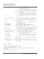
Table of Contents
1 Introduction
9
CodeWarrior IDE . . . . . . . . . . . . . . . . . . . . . . . . . . . 9
Motorola 56800/E Hybrid Controllers . . . . . . . . . . . . . . . . . . 11
References. . . . . . . . . . . . . . . . . . . . . . . . . . . . . 11
2 Getting Started
13
System Requirements . . . . . . . . . . . . . . . . . . . . . . . . 13
Installing the CodeWarrior IDE . . . . . . . . . . . . . . . . . . . . 13
Creating a Project . . . . . . . . . . . . . . . . . . . . . . . . . . 15
3 Development Studio Overview
29
CodeWarrior IDE . . . . . . . . . . . . . . . . . . . . . . . . . . 29
Development Process . . . . . . . . . . . . . . . . . . . . . . . . 30
Project Files . . . . . . . . . . . . . . . . . . . . . . . . . . . 32
Editing Code
. . . . . . . . . . . . . . . . . . . . . . . . . . 33
Building: Compiling and Linking . . . . . . . . . . . . . . . . . . 34
Debugging . . . . . . . . . . . . . . . . . . . . . . . . . . . 36
4 Target Settings
37
Target Settings Overview . . . . . . . . . . . . . . . . . . . . . . . 37
Target Setting Panels . . . . . . . . . . . . . . . . . . . . . . . 37
Changing Target Settings
. . . . . . . . . . . . . . . . . . . . . 39
Exporting and Importing Panel Options to XML Files . . . . . . . . . . 41
Restoring Target Settings
. . . . . . . . . . . . . . . . . . . . . 41
CodeWarrior IDE Target Settings Panels . . . . . . . . . . . . . . . . . 42
DSP56800E-Specific Target Settings Panels . . . . . . . . . . . . . . . 43
Target Settings . . . . . . . . . . . . . . . . . . . . . . . . . . 43
M56800E Target . . . . . . . . . . . . . . . . . . . . . . . . . 44
C/C++ Language . . . . . . . . . . . . . . . . . . . . . . . . . 45
Targeting MC56F83xx/DSP5685x Controllers
3
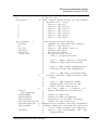
Table of Contents
C/C++ Preprocessor
. . . . . . . . . . . . . . . . . . . . . . . 48
C/C++ Warnings . . . . . . . . . . . . . . . . . . . . . . . . . 50
M56800E Assembler . . . . . . . . . . . . . . . . . . . . . . . 54
M56800E Processor
. . . . . . . . . . . . . . . . . . . . . . . 56
ELF Disassembler . . . . . . . . . . . . . . . . . . . . . . . . 59
M56800E Linker . . . . . . . . . . . . . . . . . . . . . . . . . 61
Remote Debugging . . . . . . . . . . . . . . . . . . . . . . . . 66
M56800E Target (Debugging)
. . . . . . . . . . . . . . . . . . . 67
Remote Debug Options . . . . . . . . . . . . . . . . . . . . . . 71
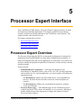
5 Processor Expert Interface
75
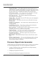
Processor Expert Overview . . . . . . . . . . . . . . . . . . . . . . 75
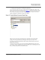
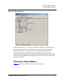
Processor Expert Code Generation . . . . . . . . . . . . . . . . . . 76
Processor Expert Beans . . . . . . . . . . . . . . . . . . . . . . 78
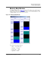
Processor Expert Menu . . . . . . . . . . . . . . . . . . . . . . 79
Processor Expert Windows . . . . . . . . . . . . . . . . . . . . . . 83
Bean Selector . . . . . . . . . . . . . . . . . . . . . . . . . . 83
Bean Inspector . . . . . . . . . . . . . . . . . . . . . . . . . . 84
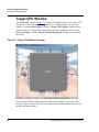
Target CPU Window . . . . . . . . . . . . . . . . . . . . . . . 86
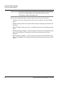
Memory Map Window
. . . . . . . . . . . . . . . . . . . . . . 91
CPU Types Overview . . . . . . . . . . . . . . . . . . . . . . . 92
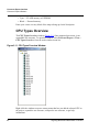
Resource Meter . . . . . . . . . . . . . . . . . . . . . . . . . 93
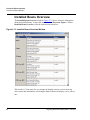
Installed Beans Overview
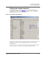
Peripherals Usage Inspector
. . . . . . . . . . . . . . . . . . . . . 94
. . . . . . . . . . . . . . . . . . . . 95
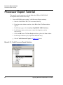
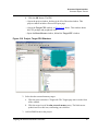
Processor Expert Tutorial . . . . . . . . . . . . . . . . . . . . . . . 96
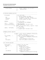
6 C for DSP56800E
113
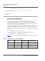
Number Formats . . . . . . . . . . . . . . . . . . . . . . . . . . 113
Calling Conventions and Stack Frames . . . . . . . . . . . . . . . . . 115
Passing Values to Functions
. . . . . . . . . . . . . . . . . . . . 115
Returning Values From Functions . . . . . . . . . . . . . . . . . . 116
Volatile and Non-Volatile Registers
Stack Frame and Alignment
4
. . . . . . . . . . . . . . . . . 116
. . . . . . . . . . . . . . . . . . . . 119
Targeting MC56F83xx/DSP5685x Controllers
Table of Contents
User Stack Allocation . . . . . . . . . . . . . . . . . . . . . . . . 120
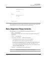
Data Alignment Requirements . . . . . . . . . . . . . . . . . . . . . 125
Word and Byte Pointers . . . . . . . . . . . . . . . . . . . . . . 126
Reordering Data for Optimal Usage
. . . . . . . . . . . . . . . . . 126
Code and Data Storage . . . . . . . . . . . . . . . . . . . . . . . . 127
Large Data Model Support . . . . . . . . . . . . . . . . . . . . . . 129
Extended Data Addressing Example . . . . . . . . . . . . . . . . . 130
Accessing Data Objects Examples . . . . . . . . . . . . . . . . . . 130
External Library Compatibility . . . . . . . . . . . . . . . . . . . 132
Optimizing Code . . . . . . . . . . . . . . . . . . . . . . . . . . 132
Deadstripping and Link Order . . . . . . . . . . . . . . . . . . . . . 133
7 Inline Assembly Language and Intrinsics
135
Inline Assembly Language . . . . . . . . . . . . . . . . . . . . . . 135
Inline Assembly Overview . . . . . . . . . . . . . . . . . . . . . 136
Assembly Language Quick Guide . . . . . . . . . . . . . . . . . . 137
Calling Assembly Language Functions from C Code . . . . . . . . . . . 138
Calling Functions from Assembly Language . . . . . . . . . . . . . . 140
Intrinsic Functions . . . . . . . . . . . . . . . . . . . . . . . . . 141
Implementation . . . . . . . . . . . . . . . . . . . . . . . . . 141
Fractional Arithmetic . . . . . . . . . . . . . . . . . . . . . . . 142
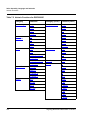
Intrinsic Functions for Math Support . . . . . . . . . . . . . . . . . 143
Modulo Addressing Intrinsic Functions . . . . . . . . . . . . . . . . 177
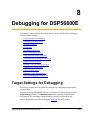
8 Debugging for DSP56800E
189
Target Settings for Debugging . . . . . . . . . . . . . . . . . . . . . 189
Command Converter Server . . . . . . . . . . . . . . . . . . . . . . 190
Essential Target Settings for Command Converter Server . . . . . . . . . 191
Changing the Command Converter Server Protocol to Parallel Port . . . . . 191
Changing the Command Converter Server Protocol to PCI . . . . . . . . 194
Setting Up a Remote Connection
. . . . . . . . . . . . . . . . . . 194
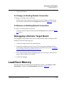
Debugging a Remote Target Board . . . . . . . . . . . . . . . . . . 197
Load/Save Memory . . . . . . . . . . . . . . . . . . . . . . . . . 197
Targeting MC56F83xx/DSP5685x Controllers
5
Table of Contents
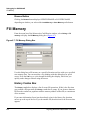
Fill Memory . . . . . . . . . . . . . . . . . . . . . . . . . . . . 200
Save/Restore Registers . . . . . . . . . . . . . . . . . . . . . . . . 202
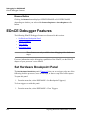
EOnCE Debugger Features . . . . . . . . . . . . . . . . . . . . . . 204
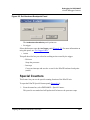
Set Hardware Breakpoint Panel . . . . . . . . . . . . . . . . . . . 204
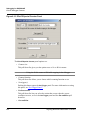
Special Counters . . . . . . . . . . . . . . . . . . . . . . . . . 205
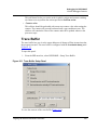
Trace Buffer
. . . . . . . . . . . . . . . . . . . . . . . . . . 207
Set Trigger Panel . . . . . . . . . . . . . . . . . . . . . . . . . 209
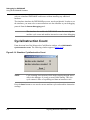
Using the DSP56800E Simulator . . . . . . . . . . . . . . . . . . . . 211
Cycle/Instruction Count . . . . . . . . . . . . . . . . . . . . . . 212
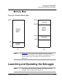
Memory Map . . . . . . . . . . . . . . . . . . . . . . . . . . 213
Launching and Operating the Debugger . . . . . . . . . . . . . . . . . 213
Setting Breakpoints . . . . . . . . . . . . . . . . . . . . . . . . 217
Setting Watchpoints . . . . . . . . . . . . . . . . . . . . . . . . 218
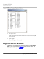
Viewing and Editing Register Values . . . . . . . . . . . . . . . . . 218
Register Details Window . . . . . . . . . . . . . . . . . . . . . . . 220
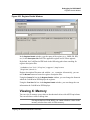
Viewing X: Memory
. . . . . . . . . . . . . . . . . . . . . . . 221
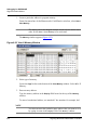
Viewing P: Memory
. . . . . . . . . . . . . . . . . . . . . . . 223
Loading a .elf File without a Project. . . . . . . . . . . . . . . . . . . 226
Command-Line Debugging . . . . . . . . . . . . . . . . . . . . . . 227
Tcl Support . . . . . . . . . . . . . . . . . . . . . . . . . . . 227
Command-Line Debugging Commands . . . . . . . . . . . . . . . . 232
System-Level Connect . . . . . . . . . . . . . . . . . . . . . . . . 264
Debugging in the Flash Memory . . . . . . . . . . . . . . . . . . . . 265
Flash Memory Commands . . . . . . . . . . . . . . . . . . . . . 265
Notes for Debugging on Hardware . . . . . . . . . . . . . . . . . . . 267
9 High-Speed Simultaneous Transfer
269
Host-Side Client Interface . . . . . . . . . . . . . . . . . . . . . . 269
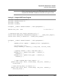
HSST Host Program Example
. . . . . . . . . . . . . . . . . . . 276
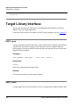
Target Library Interface . . . . . . . . . . . . . . . . . . . . . . . 278
HSST Target Program Example . . . . . . . . . . . . . . . . . . . 285
6
Targeting MC56F83xx/DSP5685x Controllers
Table of Contents
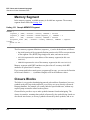
10 ELF Linker and Command Language
287
Structure of Linker Command Files . . . . . . . . . . . . . . . . . . . 287
Memory Segment
Closure Blocks
. . . . . . . . . . . . . . . . . . . . . . . . 288
. . . . . . . . . . . . . . . . . . . . . . . . . 288
Sections Segment
. . . . . . . . . . . . . . . . . . . . . . . . 289
Linker Command File Syntax . . . . . . . . . . . . . . . . . . . . . 290
Alignment
. . . . . . . . . . . . . . . . . . . . . . . . . . . 290
Arithmetic Operations . . . . . . . . . . . . . . . . . . . . . . . 291
Comments . . . . . . . . . . . . . . . . . . . . . . . . . . . 291
Deadstrip Prevention . . . . . . . . . . . . . . . . . . . . . . . 292
Variables, Expressions, and Integral Types . . . . . . . . . . . . . . . 292
File Selection . . . . . . . . . . . . . . . . . . . . . . . . . . 294
Function Selection . . . . . . . . . . . . . . . . . . . . . . . . 294
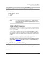
ROM to RAM Copying . . . . . . . . . . . . . . . . . . . . . . 295
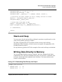
Stack and Heap
. . . . . . . . . . . . . . . . . . . . . . . . . 297
Writing Data Directly to Memory . . . . . . . . . . . . . . . . . . 297
Linker Command File Keyword Listing . . . . . . . . . . . . . . . . . 298
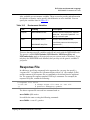
DSP56800E Command-Line Tools . . . . . . . . . . . . . . . . . . 308
Usage . . . . . . . . . . . . . . . . . . . . . . . . . . . . . 308
Response File . . . . . . . . . . . . . . . . . . . . . . . . . . 309
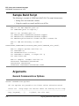
Sample Build Script
. . . . . . . . . . . . . . . . . . . . . . . 310
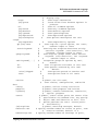
Arguments . . . . . . . . . . . . . . . . . . . . . . . . . . . 310
11 Libraries and Runtime Code
325
MSL for DSP56800E . . . . . . . . . . . . . . . . . . . . . . . . 325
Using MSL for DSP56800E
. . . . . . . . . . . . . . . . . . . . 325
Allocating Stacks and Heaps for the DSP56800E . . . . . . . . . . . . 328
Runtime Initialization . . . . . . . . . . . . . . . . . . . . . . . . 329
EOnCE Library . . . . . . . . . . . . . . . . . . . . . . . . . . . 332
Definitions . . . . . . . . . . . . . . . . . . . . . . . . . . . 343
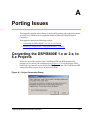
A Porting Issues
Converting the DSP56800E 1.x or 2.x, to 6.x Projects
Targeting MC56F83xx/DSP5685x Controllers
353
. . . . . . . . . . . 353
7
Table of Contents
Removing "illegal object_c on pragma directive" Warning . . . . . . . . . . 354
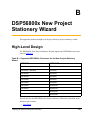
B DSP56800x New Project Stationery Wizard
355
High-Level Design . . . . . . . . . . . . . . . . . . . . . . . . . 355
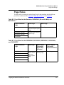
Page Rules . . . . . . . . . . . . . . . . . . . . . . . . . . . 357
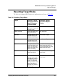
Resulting Target Rules
. . . . . . . . . . . . . . . . . . . . . . 359
Rule Notes . . . . . . . . . . . . . . . . . . . . . . . . . . . 360
DSP56800x New Project Stationery Wizard Graphical User Interface . . . . . 360
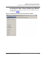
Invoking the New Project Stationery Wizard . . . . . . . . . . . . . . 361
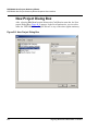
New Project Dialog Box . . . . . . . . . . . . . . . . . . . . . . 362
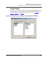
Target Pages
. . . . . . . . . . . . . . . . . . . . . . . . . . 363
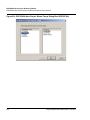
Program Choice Page without Processor Expert Option Page
. . . . . . . 366
Program Choice Page with Processor Expert Option Page . . . . . . . . . 367
Data Memory Model Page . . . . . . . . . . . . . . . . . . . . . 369
External/Internal Memory Page . . . . . . . . . . . . . . . . . . . 370
Finish Page . . . . . . . . . . . . . . . . . . . . . . . . . . . 371
C Pragmas for the DSP56800 and DSP56800E
373
Pragma Syntax . . . . . . . . . . . . . . . . . . . . . . . . . . . 373
Pragma Scope . . . . . . . . . . . . . . . . . . . . . . . . . . . 374
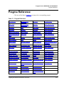
Pragma Reference . . . . . . . . . . . . . . . . . . . . . . . . . . 375
Illegal Pragmas . . . . . . . . . . . . . . . . . . . . . . . . . . . 432
Checking Settings . . . . . . . . . . . . . . . . . . . . . . . . . . 432
8
Targeting MC56F83xx/DSP5685x Controllers
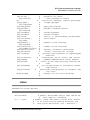
1
Introduction
This manual explains how to use the CodeWarrior™ Integrated Development
Environment (IDE) to develop code for the DSP56800E family of processors
(MC56F3xx and DSP56F5x).
This chapter contains the following sections:
• CodeWarrior IDE
• Motorola 56800/E Hybrid Controllers
• References
CodeWarrior IDE
The CodeWarrior IDE consists of a project manager, a graphical user interface,
compilers, linkers, a debugger, a source-code browser, and editing tools. You can edit,
navigate, examine, compile, link, and debug code, within the one CodeWarrior
environment. The CodeWarrior IDE lets you configure options for code generation,
debugging, and navigation of your project.
Unlike command-line development tools, the CodeWarrior IDE organizes all files
related to your project. You can see your project at a glance, so organization of your
source-code files is easy. Navigation among those files is easy, too.
When you use the CodeWarrior IDE, there is no need for complicated build scripts of
makefiles. To add files to your project or delete files from your project, you use your
mouse and keyboard, instead of tediously editing a build script.
For any project, you can create and manage several configurations for use on different
computer platforms. The platform on which you run the CodeWarrior IDE is called he
host. From the host, you use the CodeWarrior IDE to develop code to target various
platforms.
Note the two meanings of the term target:
• Platform Target — The operating system, processor, or microcontroller fin
which/on which your code will execute.
Targeting MC56F83xx/DSP5685x Controllers
9
Introduction
CodeWarrior IDE
• Build Target — The group of settings and files that determine what your code is,
as well as control the process of compiling and linking.
The CodeWarrior IDE lets you specify multiple build targets. For example, a project
can contain one build target for debugging and another build target optimized for a
particular operating system (platform target). These build targets can share files, even
though each build target uses its own settings. After you debug the program, the only
actions necessary to generate a final version are selecting the project’s optimized build
target and using a single Make command.
The CodeWarrior IDE’s extensible architecture uses plug-in compilers and linkers to
target various operating systems and microprocessors. For example, the IDE uses a
GNU tool adapter for internal calls to DSP56800E development tools.
Most features of the CodeWarrior IDE apply to several hosts, languages, and build
targets. However, each build target has its own unique features. This manual explains
the features unique to the CodeWarrior Development Studio for Motorola 56800/E
Hybrid Controllers.
For comprehensive information about the CodeWarrior IDE, see the CodeWarrior
IDE User’s Guide.
NOTE
10
For the very latest information on features, fixes, and other matters,
see the CodeWarrior Release Notes, on the CodeWarrior IDE CD.
Targeting MC56F83xx/DSP5685x Controllers
Introduction
Motorola 56800/E Hybrid Controllers
Motorola 56800/E Hybrid Controllers
The Motorola 56800/E Hybrid Controllers consist of two sub-families, which are
named the DSP56F80x/DSP56F82x (DSP56800) and the MC56F83xx/DSP5685x
(DSP56800E). The DSP56800E is an enhanced version of the DSP56800.
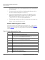
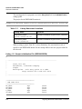
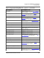
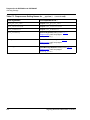
The processors in the the DSP56800 and DSP56800E sub-families are shown in Table
1.1.
With this product the following Targeting Manuals are included:
• Code Warrior Development Studio for Motorola 56800/E Hybrid Controllers:
DSP56F80x/DSP56F82x Family Targeting Manual
• Code Warrior Development Studio for Motorola 56800/E Hybrid Controllers:
MC56F83xx/DSP5685x Family Targeting Manual
NOTE
Please refer to the Targeting Manual specific to your processor.
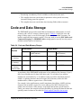
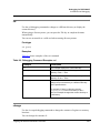
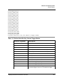
Table 1.1 Supported DSP56800x Processors for CodeWarrior Development Studio
for Motorola 56800/E Hybrid Controllers
DSP56800
DSP56800E
DSP56F801 (60 MHz)
DSP56852
DSP56F801 (80 MHz)
DSP56853
DSP56F802
DSP56854
DSP56F803
DSP56855
DSP56F805
DSP56857
DSP56F807
DSP56858
DSP56F826
MC56F8322
DSP56F827
MC56F8323
MC56F8345
MC56F8346
References
• Your CodeWarrior IDE includes these manuals:
Targeting MC56F83xx/DSP5685x Controllers
11
Introduction
References
– Code Warrior IDE User’s Guide
– Code Warrior Development Studio for Motorola 56800/E Hybrid Controllers:
DSP56F80x/DSP56F82x Family Targeting Manual
– Code Warrior Development Studio for Motorola 56800/E Hybrid Controllers:
MC56F83xx/DSP5685x Family Targeting Manual
– Assembler Reference Manual
– MSL C Reference (Metrowerks Standard C libraries)
– DSP56800 to DSP56800E Porting Guide. Motorola, Inc., 2002
– To learn more about the DSP56800E processor, refer to Motorola’s manual,
DSP56800E Family Manual, 2000.
To download electronic copies of these manuals or order printed versions, visit:
http://www.motorola.com/
12
Targeting MC56F83xx/DSP5685x Controllers
2
Getting Started
This chapter explains the setup and installation for the CodeWarrior™ IDE, including
hardware connections and communications protocols.
This chapter contains these sections:
• System Requirements
• Installing the CodeWarrior IDE
• Creating a Project
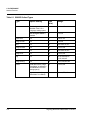
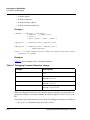
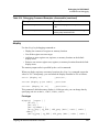
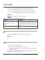
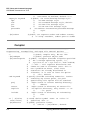
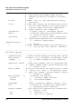
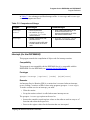
System Requirements
Table 2.1 lists system requirements for installing and using the CodeWarrior IDE for
DSP56800E.
Table 2.1 Requirements for the CodeWarrior IDE
Category
Requirement
Host Computer
Hardware
PC or compatible host computer with 133-megahertz Pentium®compatible processor, 64 megabytes of RAM, and a CD-ROM drive
Operating System
Microsoft® Windows® 98/2000/NT/XP
Hard Drive
600 megabytes of free space, plus space for user projects and source
code
DSP56800E
56800E EVM or custom 56800E development board, with JTAG
header
Other
Power supply
Installing the CodeWarrior IDE
Follow these steps:
Targeting MC56F83xx/DSP5685x Controllers
13
Getting Started
Installing the CodeWarrior IDE
1. Insert the CodeWarrior CD-ROM into your CD-ROM drive — an initial
welcome screen appears.
NOTE
If Auto Install is disabled, run program setup.exe, in the root
directory of the CD-ROM.
2. Click the Install button — the wizard welcome message box appears.
3. Follow the instructions of successive screens, clicking the Next or Yes button to
accept default values.
4. When a message asks about checking for updates, click the Yes button — the
CodeWarrior updater opens.
5. Click Check for Updates — the updater uses your internet browser to check for
available updates.
6. If updates are available, follow on-screen instructions to download the updates to
your computer.
7. When you see the message, Your version ... is up to date, click the OK button —
the message box closes.
8. Click the updater Close button — installation resumes. At the end of installation,
the wizard prompts you to restart your computer.
9. Select the Yes, restart option, then click the Finish button — the computer
restarts.
10. Follow screen instructions to register your CodeWarrior software — Metrowerks
emails your license key.
11. Install the license key:
a. Use NotePad or any standard text editor to open file license.dat, in your
CodeWarrior installation folder. (The default path is C: \Program
Files\Metrowerks\ CodeWarrior\license.dat.)
b. Start a new line at the bottom of this file.
c. Copy or type the license key onto the new line.
14
Targeting MC56F83xx/DSP5685x Controllers
Getting Started
Creating a Project
NOTE
Do not move the license.dat file after installation.
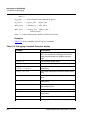
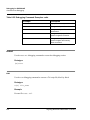
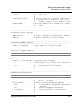
12. This completes installation: your CodeWarrior software is ready for use.
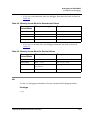
a. Table 2.2 lists the directories created during full installation.
b. To test your system, follow the instructions of the next section to create a
project.
Table 2.2 Installation Directories, CodeWarrior IDE for DSP56800E
Directory
Contents
Bin
The CodeWarrior IDE application and associated plug-in
tools.
CCS
Command converter server executable files and related
support files.
CodeWarrior Examples
Target-specific projects and code.
CodeWarrior Help
Core IDE and target-specific help files. (Access help files
through the Help menu or F1 key.)
CodeWarrior Manuals
The CodeWarrior documentation tree.
CW Release Notes
Release notes for the CodeWarrior IDE and each tool.
Licensing
The registration program and additional licensing
information.
M56800E_EABI_Tools
Drivers for the CCS and command line tools, plus IDE
default files for DSP56800E stationery.
M56800E Support
Metrowerks Standard Library (MSL).
Motorola Documentation
Documentation specific to the Motorola DSP56800E
series.
Stationery
Templates for creating DSP56800E projects. Each
template pertains to a specific debugging protocol.
Creating a Project
To test software installation, create a sample project. Follow these steps:
1. Select Start>Metrowerks CodeWarrior>CodeWarrior for
DSP56800R6.0>CodeWarrior IDE. The IDE starts; the main window appears.
Targeting MC56F83xx/DSP5685x Controllers
15
Getting Started
Creating a Project
To create a DSP56800x project use either the:
• DSP56800x new project wizard
• DSP56800x EABI stationery
To create a new project with the DSP56800x new project wizard, please see the subsection “Creating a New Project with the DSP56800x New Project Wizard.”
To create a new project with the DSP56800x EABI stationery, please see the subsection “Creating a New Project with the DSP56800x EABI Stationery.”
Creating a New Project with the DSP56800x New
Project Wizard
In this section of the tutorial, you work with the CodeWarrior IDE to create a project.
with the DSP56800x New Project Wizard.
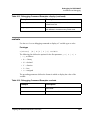
To create a project:
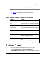
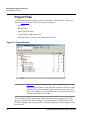
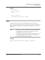
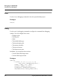
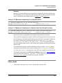
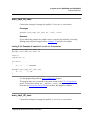
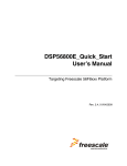
1. From the menu bar of the Metrowerks CodeWarrior window, select File>New.
The New dialog box (Figure 2.1) appears.
16
Targeting MC56F83xx/DSP5685x Controllers
Getting Started
Creating a Project
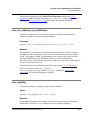
Figure 2.1 New Dialog Box
2. Select DSP56800x New Project Wizard.
3. In the Project Name text box, type the project name. For example, the_project.
4. In the Location text box, type the location where you want to save this project or
choose the default location.
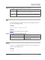
5. Click OK. The DSP56800x New Project Wizard
2.2) appears.
Targeting MC56F83xx/DSP5685x Controllers
— Target
dialog box (Figure
17
Getting Started
Creating a Project
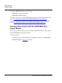
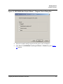
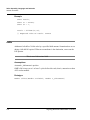
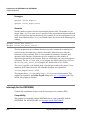
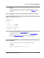
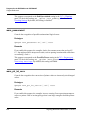
Figure 2.2 DSP56800x New Project Wizard — Target Dialog Box
6. Select the target board and processor
a. Select the family, such as DSPF6F80x, from the DSP56800x Family list.
b. Select a processor or simulator, such as 56800 simulator, from the Processors
list.
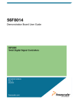
7. Click Next. The DSP56800x New Project Wizard — Program Choice dialog
box (Figure 2.3) appears.
18
Targeting MC56F83xx/DSP5685x Controllers
Getting Started
Creating a Project
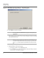
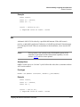
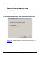
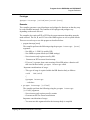
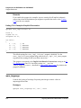
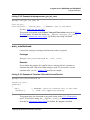
Figure 2.3 DSP56800x New Project Wizard — Program Choice Dialog Box
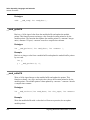
8. Select the example main[] program for this project, such as Simple C.
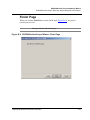
9. Click Next. The DSP56800x New Project Wizard — Finish dialog box (Figure
2.4) appears.
Targeting MC56F83xx/DSP5685x Controllers
19
Getting Started
Creating a Project
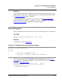
Figure 2.4 DSP56800x New Project Wizard — Finish Dialog Box
10. Click Finish to create the new project.
NOTE
For more details of the DSP56800x new project wizard, please see
Appendix B.
This completes project creation. You are ready to edit project contents, according
to the optional steps below.
NOTE
Stationery projects include source files that are placeholders for your
own files. If a placeholder file has the same name as your file (such
as main.c), you must replace the placeholder file with your source
file.
11. (Optional) Remove files from the project.
a. In the project window, select (highlight) the files.
b. Press the Delete key (or right-click the filename, then select Remove from the
context menu). The filenames disappear.
20
Targeting MC56F83xx/DSP5685x Controllers
Getting Started
Creating a Project
12. (Optional) Add source files to the project.
a. Method 1: From the main-window menu bar, select Project>Add Files. Then
use the Select files to add dialog box to specify the files.
b. Method 2: Drag files from the desktop or Windows Explorer to the project
window.
13. (Optional) Edit code in the source files.
a. Double-click the filename in the project window (or select the filename, then
press the Enter key).
b. The IDE opens the file in the editor window; you are ready to edit file
contents.
Creating a New Project with the DSP56800x EABI
Stationery
To create a sample project. Follow these steps:
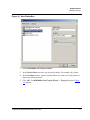
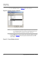
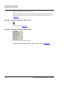
1. From the menu bar, select File>New. The New window (Figure 2.5) appears.
Figure 2.5 New Window
Targeting MC56F83xx/DSP5685x Controllers
21
Getting Started
Creating a Project
2. Specify a new DSP56800E project named NewProj1.
a. If necessary, click the Project tab to move the Project page to the front of the
window.
b. From the project list, select (highlight) DSP56800E EABI Stationery.
NOTE
Stationery is a set of project templates, including libraries and placeholders for source code. Using stationery is the quickest way to
create a new project.
c. In the Project name text box, type: NewProj1. (When you save this project,
the IDE automatically will add the .mcp extension to its filename.)
3. (Optional) Change the default project location.
a. Click the Set button. The Create New Project dialog box dialog box (Figure
2.6) appears:
Figure 2.6 Create New Project Dialog Box
b. Use the standard navigation controls of this dialog box to specify the path for
the project file. (Check the Create Folder checkbox to have the IDE create a
new folder for your project.)
c. Click the Save button. The IDE saves the specified pathname; the Create
New Project dialog box closes.
22
Targeting MC56F83xx/DSP5685x Controllers
Getting Started
Creating a Project
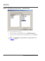
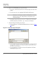
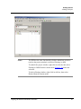
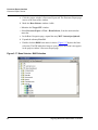
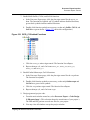
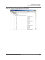
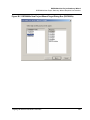
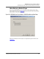
4. In the New window, click the OK button. The New Project window (Figure 2.7)
appears, listing board-specific project stationery.
Figure 2.7 New Project Window
5. Select the simulator C stationery target.
a. Click the expand control (+) for the M56800E Simulator. The tree expands to
show stationery selections.
Targeting MC56F83xx/DSP5685x Controllers
23
Getting Started
Creating a Project
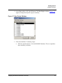
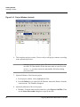
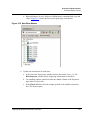
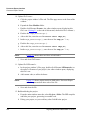
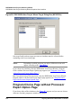
b. Select (highlight) Simple C. (Figure 2.8 shows this selection.)
Figure 2.8 Simulator Simple C Selection
NOTE
You should select a simulator target if your system is not connected
to a development board. If you do have a development board, your
target selection must correspond to the board’s processor.
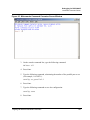
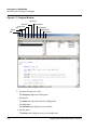
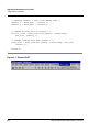
c. Click the OK button. A project window opens, listing the folders for project
NewProj1.mcp. Figure 2.9 shows this project window docked in the IDE
main window.
Figure 2.9 Project Window (docked)
24
Targeting MC56F83xx/DSP5685x Controllers
Getting Started
Creating a Project
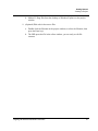
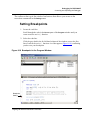
NOTE
The IDE has the same functionality whether subordinate windows
(such as the project window) are docked, floating, or child.
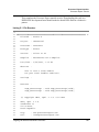
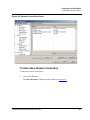
To undock the project window, right-click its title tab, then select
Floating or Child from the context menu. Figure 2.10 shows this
selection.
To dock a floating window, right-click its title bar, then select
Docked from the context menu.
Targeting MC56F83xx/DSP5685x Controllers
25
Getting Started
Creating a Project
Figure 2.10 Project Window (docked)
6. This completes project creation. You are ready to edit project contents, according
to the optional steps below.
NOTE
Stationery projects include source files that are placeholders for your
own files. If a placeholder file has the same name as your file (such
as main.c), you must remove the placeholder file before adding
your source file.
7. (Optional) Remove files from the project.
a. In the project window, select (highlight) the files.
b. Press the Delete key (or right-click the filename, then select Remove from the
context menu). The filenames disappear.
8. (Optional) Add source files to the project.
a. Method 1: From the main-window menu bar, select Project>Add Files. Then
use the Select files to add dialog box to specify the files.
26
Targeting MC56F83xx/DSP5685x Controllers
Getting Started
Creating a Project
b. Method 2: Drag files from the desktop or Windows Explorer to the project
window.
9. (Optional) Edit code in the source files.
a. Double-click the filename in the project window (or select the filename, then
press the Enter key).
b. The IDE opens the file in the editor window; you are ready to edit file
contents.
Targeting MC56F83xx/DSP5685x Controllers
27
Getting Started
Creating a Project
28
Targeting MC56F83xx/DSP5685x Controllers
3
Development Studio
Overview
This chapter describes the CodeWarrior™ IDE and explains application development
using the IDE. This chapter contains these sections:
• CodeWarrior IDE
• Development Process
If you are an experienced CodeWarrior IDE user, you will recognize the look and feel
of the user interface. However, you must become familiar with the DSP56800E
runtime software environment.
CodeWarrior IDE
The CodeWarrior IDE lets you create software applications. It controls the project
manager, the source-code editor, the class browser, the compiler, linker, and the
debugger.
You use the project manager to organize all the files and settings related to your
project. You can see your project at a glance and easily navigate among source-code
files. The CodeWarrior IDE automatically manages build dependencies.
A project can have multiple build targets. A build target is a separate build (with its
own settings) that uses some or all of the files in the project. For example, you can
have both a debug version and a release version of your software as separate build
targets within the same project.
The CodeWarrior IDE has an extensible architecture that uses plug-in compilers and
linkers to target various operating systems and microprocessors. The CodeWarrior CD
includes a C compiler for the DSP56800E family of processors. Other CodeWarrior
software packages include C, C++, and Java compilers for Win32, Mac OS, Linux,
and other hardware and software combinations.
The IDE includes:
Targeting MC56F83xx/DSP5685x Controllers
29
Development Studio Overview
Development Process
• CodeWarrior Compiler for DSP56800E — an ANSI-compliant C compiler,
based on the same compiler architecture used in all CodeWarrior C compilers.
Use this compiler with the CodeWarrior linker for DSP56800E to generate
DSP56800E applications and libraries.
NOTE
The CodeWarrior compiler for DSP56800E does not support C++.
• CodeWarrior Assembler for DSP56800E — an assembler that features easyto-use syntax. It assembles any project file that has a.asm filename extension.
For further information, refer to the Assembler Reference Manual.
• CodeWarrior Linker for DSP56800E — a linker that lets you generate either
Executable and Linker Format (ELF) or S-record output files for your
application.
• CodeWarrior Debugger for DSP56800E — a debugger that controls your
program’s execution, letting you see what happens internally as your program
runs. Use this debugger to find problems in your program.
The debugger can execute your program one statement at a time, suspending
execution when control reaches a specified point. When the debugger stops a
program, you can view the chain of function calls, examine and change the values
of variables, inspect processor register contents, and see the contents of memory.
• Metrowerks Standard Library (MSL) — a set of ANSI-compliant, standard C
libraries for use in developing DSP56800E applications. Access the library
sources for use in your projects. A subset of those used for all platform targets,
these libraries are customized and the runtime adapted for DSP56800E
development.
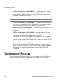
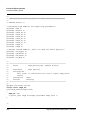
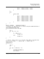
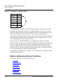
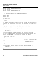
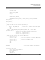
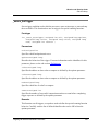
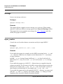
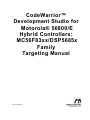
Development Process
The CodeWarrior IDE helps you manage your development work more effectively
than you can with a traditional command-line environment. Figure 3.1 depicts
application development using the IDE.
30
Targeting MC56F83xx/DSP5685x Controllers
Development Studio Overview
Development Process
Figure 3.1 CodeWarrior IDE Application Development
Start
Create/Manage Project
Manage Files (1)
Specify Target
(2)
Settings
Edit Files
(3)
Notes:
(1) Use any combination: stationery
(template) files, library files,
or your own source files.
(2) Compiler, linker, debugger
settings; target specification;
optimizations.
Build (Make) Project
(3) Edit source and resource files.
Compile Project
Success?
(4)
no
(4) Possible corrections:
adding a file, changing
settings, or editing a file.
yes
Link Project
Success?
no
yes
Debug Project
Error-Free?
no
yes
Release
End
Targeting MC56F83xx/DSP5685x Controllers
31
Development Studio Overview
Development Process
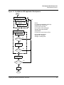
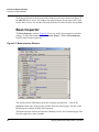
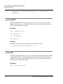
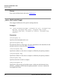
Project Files
A CodeWarrior project consists of source-code, library, and other files. The project
window (Figure 3.2) lists all files of a project, letting you:
• Add files,
• Remove files,
• Specify the link order,
• Assign files to build targets, and
• Direct the IDE to generate debug information for files.
Figure 3.2 Project Window
NOTE
Figure 3.2 shows a floating project window. Alternatively, you can
dock the project window in the IDE main window or make it a child
window. You can have multiple project windows open at the same
time; if the windows are docked, their tabs let you control which one
is at the front of the main window.
The CodeWarrior IDE automatically handles the dependencies among project files,
and stores compiler and linker settings for each build target. The IDE tracks which
files have changed since your last build, recompiling only those files during your next
project build.
32
Targeting MC56F83xx/DSP5685x Controllers
Development Studio Overview
Development Process
A CodeWarrior project is analogous to a collection of makefiles, as the same project
can contain multiple builds. Examples are a debug version and a release version of
code, both part of the same project. As earlier text explained, build targets are such
different builds within a single project.
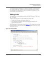
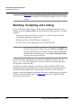
Editing Code
The CodeWarrior text editor handles text files in MS-DOS, Windows, UNIX, and
Mac OS formats.
To edit a source-code file (or any other editable project file), either:
• Double-click its filename in the project window, or
• Select (highlight) the filename, then drag the highlighted filename to the
CodeWarrior main window.
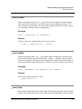
The IDE opens the file in the editor window (Figure 3.3). This window lets you switch
between related files, locate particular functions, mark locations within a file, or go to
a specific line of code.
Figure 3.3 Editor Window
CodeWarrior Build System
Targeting MC56F83xx/DSP5685x Controllers
33
Development Studio Overview
Development Process
NOTE
Figure 3.3 shows a floating editor window. Alternatively, you can
dock the editor window in the IDE main window or make it a child
window.
Building: Compiling and Linking
For the CodeWarrior IDE, building includes both compiling and linking. To start
building, you select Project>Make, from the IDE main-window menu bar. The IDE
compiler:
• Generates an object-code file from each source-code file of the build target,
incorporating appropriate optimizations.
• Updates other files of the build target, as appropriate.
• In case of errors, issues appropriate error messages and halts.
NOTE
It is possible to compile a single source file. To do so, highlight its
filename in the project window, then select Project > Compile, from
the main-window menu bar. Another useful option is compiling all
modified files of the build target: select Project>Bring Up to Date
from the main-window menu bar.
In UNIX and other command-line environments, the IDE stores object code in a
binary (.o or .obj) file. On Windows targets, the IDE stores and manages object
files internally in the data folder.
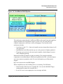
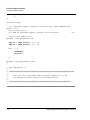
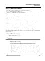
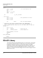
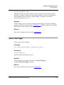
A proprietary compiler architecture at the heart of the CodeWarrior IDE handles
multiple languages and platform targets. Front-end language compilers generate an
intermediate representation (IR) of syntactically correct source code. This IR is
memory-resident and language-independent. Back-end compilers generate code from
the IR for specific platform targets. As Figure 3.4 depicts, the CodeWarrior IDE
manages this whole process.
34
Targeting MC56F83xx/DSP5685x Controllers
Development Studio Overview
Development Process
Figure 3.4 CodeWarrior Build System
This architecture means that the CodeWarrior IDE uses the same front-end compiler to
support multiple back-end platform targets. In some cases, the same back-end
compiler can generate code from a variety of languages. User benefits of this
architecture include:
• An advance in the C/C++ front-end compiler means an immediate advance in all
code generation.
• Optimizations in the IR mean that any new code generator is highly optimized.
• Targeting a new processor does not require compiler-related changes in source
code, simplifying porting.
Metrowerks builds all compilers as plug-in modules. The compiler and linker
components are modular plug-ins. Metrowerks publishes this API, so that developers
can create custom or proprietary tools. For more information, go to Metrowerks
Support:
http://www.metrowerks.com/MW/Support
When compilation succeeds, building moves on to linking. The IDE linker:
• Links the object files into one executable file. (You use the M56800E Target
settings panel to name the executable file.)
• In case of errors, issues appropriate error messages and halts.
Targeting MC56F83xx/DSP5685x Controllers
35
Development Studio Overview
Development Process
The IDE uses linker command files to control the linker, so you do not need to specify
a list of object files. The Project Manager tracks all the object files automatically; it
lets you specify the link order.
When linking succeeds, you are ready to test and debug your application.
Debugging
To debug your application, select Project>Debug from the main-window menu
bar. The debugger window opens, displaying your program code.
Run the application from within the debugger, to observe results. The debugger lets
you set breakpoints, and check register, parameter, and other values at specific points
of code execution.
When your code executes correctly, you are ready to add features, to release the
application to testers, or to release the application to customers.
NOTE
36
Another debugging feature of the CodeWarrior IDE is viewing
preprocessor output. This helps you track down bugs cause by macro
expansion or another subtlety of the preprocessor. To use this feature,
specify the output filename in the project window, then select
Project>Preprocess from the main-window menu bar. A new
window opens to show the preprocessed file.
Targeting MC56F83xx/DSP5685x Controllers
4
Target Settings
Each build target in a CodeWarrior™ project has its own settings. This chapter
explains the target settings panels for DSP56800E software development. The settings
that you select affect the DSP56800E compiler, linker, assembler, and debugger.
This chapter contains the following sections:
• Target Settings Overview
• CodeWarrior IDE Target Settings Panels
• DSP56800E-Specific Target Settings Panels
Target Settings Overview
The target settings control:
• Compiler options
• Linker options
• Assembler options
• Debugger options
• Error and warning messages
When you create a project using stationery, the build targets, which are part of the
stationery, already include default target settings. You can use those default target
settings (if the settings are appropriate), or you can change them.
NOTE
Use the DSP56800E project stationery when you create a new
project.
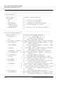
Target Setting Panels
Table 4.1 lists the target settings panels:
Targeting MC56F83xx/DSP5685x Controllers
37
Target Settings
Target Settings Overview
• Links identify the panels specific to DSP56800E projects. Click the link to go to
the explanation of that panel.
• The Use column explains the purpose of generic IDE panels that also can apply to
DSP56800E projects. For explanations of these panels, see the IDE User Guide.
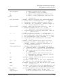
Table 4.1 Target Setting Panels
Group
Panel Name
Target
Target Settings
Use
Access Paths
Selects the paths that the IDE
searches to find files of your project.
Types include absolute and projectrelative.
Build Extras
Sets options for building a project,
including using a third-party debugger.
Runtime Settings
Sets such options as
• Host application for debugging
non-executable files
• Working directory
• Program arguments
• Environment variables.
File Mappings
Associates a filename extension, such
as .c, with a plug-in compiler.
Source Trees
Defines project -specific source trees
(root paths) for your project.
M56800E Target
Language Settings
C/C++ Language
C/C++ Preprocessor
C/C++ Warnings
M56800E Assembler
Code Generation
M56800E Processor
Global Optimization
Linker
Configures how the compiler
optimizes code.
ELF Disassembler
M56800E Linker
38
Targeting MC56F83xx/DSP5685x Controllers
Target Settings
Target Settings Overview
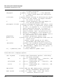
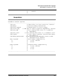
Table 4.1 Target Setting Panels (continued)
Group
Panel Name
Use
Editor
Custom Keywords
Changes colors for different types of
text.
Debugger
Debugger Settings
Specifies settings for the CodeWarrior
debugger.
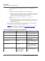
Remote Debugging
M56800E Target
(Debugging)
Remote Debug Options
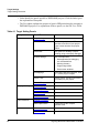
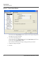
Changing Target Settings
To change target settings:
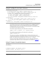
1. Select Edit > Target Name Settings.
Target
is the name of the current build target in the CodeWarrior project.
After you select this menu item, the CodeWarrior IDE displays the Target Settings
window (Figure 4.1).
Targeting MC56F83xx/DSP5685x Controllers
39
Target Settings
Target Settings Overview
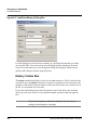
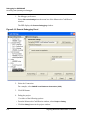
Figure 4.1 Target Settings Window
The left side of the Target Settings window contains a list of target settings panels
that apply to the current build target.
2. To view the Target Settings panel:
Click on the name of the Target Settings panel in the Target Settings panels list on
the left side of the Target Settings window.
The CodeWarrior IDE displays the target settings panel that you selected.
3. Change the settings in the panel.
4. Click OK.
40
Targeting MC56F83xx/DSP5685x Controllers
Target Settings
Target Settings Overview
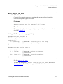
Exporting and Importing Panel Options to
XML Files
The CodeWarrior IDE can export options for the current settings panel to an
Extensible Markup Language (XML) file or import options for the current settings
panel from a previously saved XML file.
Exporting Panel Options to XML File
1. Click the Export Panel button.
2. Assign a name to the XML file and save the file in the desired location.
Importing Panel Options from XML File
1. Click the Import Panel button.
2. Locate the XML file to where you saved the options for the current settings panel.
3. Open the file to import the options.
Saving New Target Settings in Stationery
To create stationery files with new target settings:
1. Create your new project from an existing stationery.
2. Change the target settings in your new project for any or all of the build targets in
the project.
3. Save the new project in the Stationery folder.
Restoring Target Settings
After you change settings in an existing project, you can restore the previous settings
by using any of the following methods:
• To restore the previous settings, click Revert at the bottom of the Target Settings
window.
• To restore the settings to the factory defaults, click Factory Settings at the bottom
of the window.
Targeting MC56F83xx/DSP5685x Controllers
41
Target Settings
CodeWarrior IDE Target Settings Panels
CodeWarrior IDE Target Settings Panels
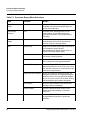
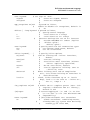
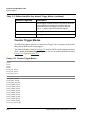
Table 4.2 lists and explains the CodeWarrior IDE target settings panels that can apply
to DSP56800E.
Table 4.2 Code Warrior IDE Target Settings Panels
42
Target Settings
Panels
Description
Access Paths
Use this panel to select the paths that the
CodeWarrior IDE searches to find files in your project.
You can add several kinds of paths including absolute
and project-relative.
See IDE User Guide.
Build Extras
Use this panel to set options that affect the way the
CodeWarrior IDE builds a project, including the use of a
third-party debugger.
See IDE User Guide.
Runtime Settings
Use this panel to set a variety of options, including:
A host application to use when debugging a nonexecutable file (for example, a shared library)
A working directory
Program arguments
Environment variables
See IDE User Guide.
File Mappings
Use this panel to associate a file name extension, such
as.c, with a plug-in compiler.
See IDE User Guide.
Source Trees
Use this panel to define project-specific source trees
(root paths) for use in your projects.
See IDE User Guide.
Custom Keywords
Use this panel to change the colors that the
CodeWarrior IDE uses for different types of text.
See IDE User Guide.
Other Executables
Use this panel to specify other executables to debug
while debugging the current target.
See IDE User Guide.
Global Optimizations
Use this panel to configure how the compiler optimizes
the object code.
See IDE User Guide.
Debugger Settings
Use this panel to specify settings for the CodeWarrior
debugger.
Targeting MC56F83xx/DSP5685x Controllers
Target Settings
DSP56800E-Specific Target Settings Panels
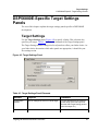
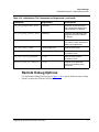
DSP56800E-Specific Target Settings
Panels
The rest of this chapter explains the target settings panels specific to DSP56800E
development.
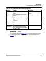
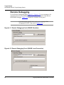
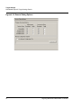
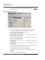
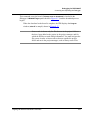
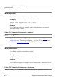
Target Settings
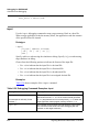
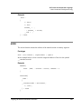
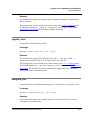
Use the Target Settings panel (Figure 4.2) to specify a linker. This selection also
specifies your target. Table 4.3 explains the elements of the Target Settings panel.
The Target Settings window changes its list of panels to reflect your linker choice. As
your linker choice determines which other panels are appropriate, it should be your
first settings action.
Figure 4.2 Target Settings Panel
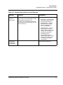
Table 4.3 Target Settings Panel Elements
Element
Purpose
Comments
Target Name
text box
Sets or changes the name of a build target.
For your development convenience,
not the name of the final output file.
(Use the AGB Target Setting panel to
name the output file.)
Linker list box
Specifies the linker.
Select M56800E Linker.
Targeting MC56F83xx/DSP5685x Controllers
43
Target Settings
DSP56800E-Specific Target Settings Panels
Table 4.3 Target Settings Panel Elements (continued)
Element
Purpose
Comments
Pre-linker list
box
Specifies a pre-linker.
Select None.
(No pre-linker is available for the
M56800E linker.)
Post-linker list
box
Specifies a post-linker.
Select None.
(No post-linker is available for the
M56800E linker.)
Output Directory
text box
Tells the IDE where to save the executable
file. To specify a different output directory,
click the Choose button, then use the
access-path dialog box to specify a
directory. (To delete such an alternate
directory, click the Clear button.)
Default: the directory that contains
the project file.
Save Project
Entries Using
Relative Paths
checkbox
Controls whether multiple project files can
have the same name:
Default: Clear — project entries must
have unique names.
• Clear — Each project entry must
have a unique name.
• Checked — The IDE uses relative
paths to save project entries; entry
names need not be unique.
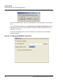
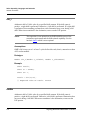
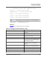
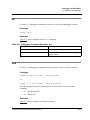
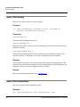
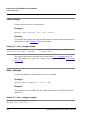
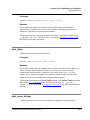
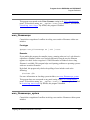
M56800E Target
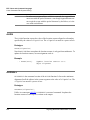
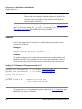
Use the M56800E Target panel (Figure 4.3) to specify the project type and the name
of the output file. Table 4.4 explains the elements of this panel.
Figure 4.3 M56800E Target Panel
44
Targeting MC56F83xx/DSP5685x Controllers
Target Settings
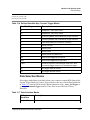
DSP56800E-Specific Target Settings Panels
Table 4.4 M56800E Target Panel Elements
Element
Purpose
Comments
Project Type list
box
Specifies an Application or Library
project.
Application is the usual selection.
Output File
Name text box
Specifies the name of the output file.
End application filenames with the .elf
extension; end library filenames with
the .lib extension.
NOTE
Be sure to name libraries with the extension .lib. It is possible to
use a different extension, but this requires a file-mapping entry in the
File Mappings panel. For more information, see the IDE User
Guide.
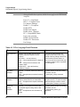
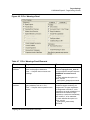
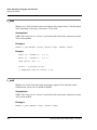
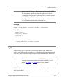
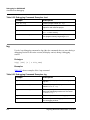
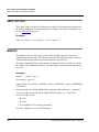
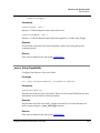
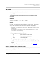
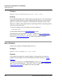
C/C++ Language
Use the C/C++ Language panel (Figure 4.4) to specify C language features. Table 4.5
explains the elements of this panel that apply to the DSP56800E processor, which
supports only the C language.
Figure 4.4 C/C++ Language Panel
Targeting MC56F83xx/DSP5685x Controllers
45
Target Settings
DSP56800E-Specific Target Settings Panels
NOTE
Always disable these options, which do not apply to the DSP56800E
compiler:
Force C++ compilation
ISO C++ Template Parser
Use Instance Manager
Enable C++ Exceptions
Enable RTTI
Enable bool Support
Enable wchar_t Support
EC++ Compatibility Mode
Legacy for-scooping
Enable C99 Extensions
Enable GCC Extensions
Pool Strings
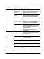
Table 4.5 C/C++ Language Panel Elements
Element
Purpose
Comments
Inline Depth list
box
Together with the ANSI Keyword Only
checkbox, specifies whether to inline
functions:
Don’t Inline — do not inline any
Smart — inline small functions to a depth of
2 to 4
1 to 8 — Always inline functions to the
number’s depth
Always inline — inline all functions,
regardless of depth
If you call an inline function, the
compiler inserts the function code,
instead of issuing calling instructions.
Inline functions execute faster, as
there is no call. But overall code may
be larger if function code is repeated
in several places.
Auto-Inline
checkbox
Checked — Compiler selects the functions
to inline
Clear — Compiler does not select functions
for inlining
To check whether automatic inlining
is in effect, use the
__option(auto_inline) command.
Deferred Inlining
checkbox
Checked — Compiler permits inlining of
functions called before their declarations.
Clear — Compiler does not permit deferred
inlining.
Deferred Inlining requires extra
compiler memory. To check whether
deferred inlining is in effect, use the
__option(defer_codegen) command.
Bottom-up
Inlining
checkbox
Checked — For a chain of function calls,
the compiler begins inlining with the last
function.
Clear — Compiler does not do bottom-up
inlining.
To check whether bottom-up inlining
is in effect, use the
__option(inline_bottom_up)
command.
46
Targeting MC56F83xx/DSP5685x Controllers
Target Settings
DSP56800E-Specific Target Settings Panels
Table 4.5 C/C++ Language Panel Elements (continued)
Element
Purpose
Comments
ANSI Strict
checkbox
Checked — Disables CodeWarrior compiler
extensions to C
Clear — Permits CodeWarrior compiler
extensions to C
Extensions are C++-style comments,
unnamed arguments in function
definitions, # not and argument in
macros, identifier after #endif,
typecasted pointers as lvalues,
converting pointers to same-size
types, arrays of zero length in
structures, and the D constant suffix.
To check whether ANSI strictness is
in effect, use the
__option(ANSI_strict) command.
ANSI Keywords
Only checkbox
Checked — Does not permit additional
keywords of CodeWarrior C.
Clear — Does permit additional keywords.
Additional keywords are asm (use the
compiler built-in assembler) and
inline (lets you declare a C function to
be inline).
To check whether this keyword
restriction is in effect, use the
__option(only_std_keywords)
command.
Expand
Trigraphs
checkbox
Checked — C Compiler ignores trigraph
characters.
Clear — C Compiler does not allow trigraph
characters, per strict ANSI/ISO standards.
Many common character constants
resemble trigraph sequences,
especially on the Mac OS. This
extension lets you use these
constants without including escape
characters.
NOTE: If this option is on, be careful
about initializing strings or multicharacter constants that include
question marks.
To check whether this option is on.
use the __option(trigraphs)
command.
Require Function
Prototypes
checkbox
Checked — Compiler does not allow
functions that do not have prototypes.
Clear — Compiler allows functions without
prototypes.
This option helps prevent errors from
calling a function before its
declaration or definition.
To check whether this option is in
effect, use the
__option(require_prototypes)
command.
Targeting MC56F83xx/DSP5685x Controllers
47
Target Settings
DSP56800E-Specific Target Settings Panels
Table 4.5 C/C++ Language Panel Elements (continued)
Element
Purpose
Comments
Enums Always
Int checkbox
Checked — Restricts all enumerators to the
size of a singed int.
Clear — Compiler converts unsigned int
enumerators to signed int, then chooses an
accommodating data type, char to long int.
To check whether this restriction is in
effect, use the
__option(enumalwasysint) command.
Use Unsigned
Chars checkbox
Checked — Compiler treats a char
declaration as an unsigned chard
declaration.
Clear — Compiler treats char and unsigned
char declarations differently.
Some libraries were compiled without
this option. Selecting this option may
make your code incompatible with
such libraries.
To check whether this option is in
effect, use the
__option(unsigned_char) command.
Reuse Strings
checkbox
Checked — Compiler stores only one copy
of identical string literals, saving memory
space.
Clear — Compiler stores each string literal.
If you select this option, changing one
of the strings affects them all.
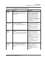
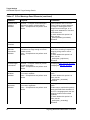
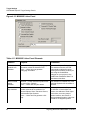
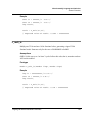
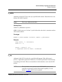
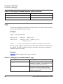
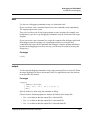
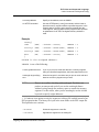
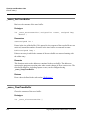
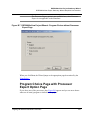
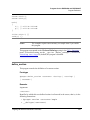
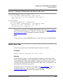
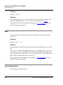
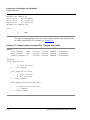
C/C++ Preprocessor
The C/C++ Preprocessor (Figure 4.5) panel controls how the preprocessor interprets
source code. By modifying the settings on this panel, you can control how the
preprocessor translates source code into preprocessed code.
More specifically, the C/C++ Preprocessor panel provides an editable text field that
can be used to #define macros, set #pragmas, or #include prefix files.
48
Targeting MC56F83xx/DSP5685x Controllers
Target Settings
DSP56800E-Specific Target Settings Panels
Figure 4.5 The C/C++ Preprocessor Panel
Table 4.6 provides information about the options in this panel.
Table 4.6 C/C++ Language Preprocessor Elements
Element
Purpose
Comments
Source encoding
Allows you to specify the default encoding
of source files. Multibyte and Unicode
source text is supported.
To replicate the obsolete option
“Multi-Byte Aware”, set this option to
System or Autodetect. Additionally,
options that affect the "preprocess"
request appear in this panel.
Use prefix text in
precompiled
header
Controls whether a *.pch or *.pch++ file
incorporates the prefix text into itself.
This option defaults to “off” to
correspond with previous versions of
the compiler that ignore the prefix file
when building precompiled headers.
If any #pragmas are imported from
old C/C++ Language Panel settings,
this option is set to “on”.
Emit file changes
Controls whether notification of file changes
(or #line changes) appear in the output.
Targeting MC56F83xx/DSP5685x Controllers
49
Target Settings
DSP56800E-Specific Target Settings Panels
Table 4.6 C/C++ Language Preprocessor Elements (continued)
Element
Purpose
Comments
Emit #pragmas
Controls whether #pragmas encountered in
the source text appear in the preprocessor
output.
This option is essential for producing
reproducible test cases for bug
reports.
Show full paths
Controls whether file changes show the full
path or the base filename of the file.
Keep comments
Controls whether comments are emitted in
the output.
Use #line
Controls whether file changes appear in
comments (as before) or in #line directives.
Keep whitespace
Controls whether whitespace is stripped out
or copied into the output.
This is useful for keeping the starting
column aligned with the original
source, though we attempt to
preserve space within the line. This
doesn’t apply when macros are
expanded.
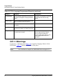
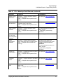
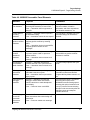
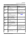
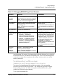
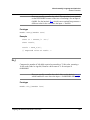
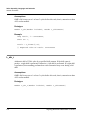
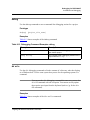
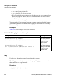
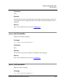
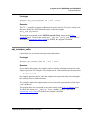
C/C++ Warnings
Use the C/C++ Warnings panel (Figure 4.6) to specify C language features for the
DSP56800E. Table 4.7 explains the elements of this panel.
NOTE
50
The CodeWarrior compiler for DSP56800E does not support C++.
Targeting MC56F83xx/DSP5685x Controllers
Target Settings
DSP56800E-Specific Target Settings Panels
Figure 4.6 C/C++ Warnings Panel
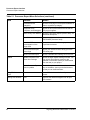
Table 4.7 C/C++ Warnings Panel Elements
Element
Purpose
Comments
Illegal Pragmas
checkbox
Checked — Compiler issues warnings
about invalid pragma statements.
Clear — Compiler does not issue such
warnings.
According to this option, the invalid
statement #pragma near_data off
would prompt the compiler response
WARNING: near data is not a
pragma.
To check whether this option is in
effect, use the
__option(warn_illpragma) command.
Possible Errors
checkbox
Checked — Compiler checks for common
typing mistakes, such as == for =.
Clear — Compiler does not perform such
checks.
If this option is in effect, any of these
conditions triggers a warning: an
assignment in a logical expression;
an assignment in a while, if, or for
expression; an equal comparison in a
statement that contains a single
expression; a semicolon immediately
after a while, if, or for statement.
To check whether this option is in
effect, use the
__option(warn_possunwant)
command.
Targeting MC56F83xx/DSP5685x Controllers
51
Target Settings
DSP56800E-Specific Target Settings Panels
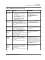
Table 4.7 C/C++ Warnings Panel Elements (continued)
Element
Purpose
Comments
Extended Error
Checking
checkbox
Checked — Compiler issues warnings in
response to specific syntax problems.
Clear — Compiler does not perform such
checks.
Syntax problems are: a non-void
function without a return statement,
an integer or floating-point value
assigned to an enum type, or an
empty return statement in a function
not declared void.
To check whether this option is in
effect, use the
__option(extended_errorcheck)
command.
Hidden Virtual
Functions
Leave clear.
Does not apply to C.
Implicit
Arithmetic
Conversions
checkbox
Checked — Compiler verifies that operation
destinations are large enough to hold all
possible results.
Clear — Compiler does not perform such
checks.
If this option is in effect, the compiler
would issue a warning in response to
assigning a long value to a char
variable.
To check whether this option is in
effect, use the
__option(warn_implicitconv)
command.
Pointer/Integral
Conversions
Checked — Compiler checks for pointer/
integral conversions.
Clear — Compiler does not perform such
checks.
See #pragma warn_any_ptr_int_conv
and #pragma warn_ptr_int_conv.
Unused
Variables
checkbox
Checked — Compiler checks for declared,
but unused, variables.
Clear — Compiler does not perform such
checks.
The pragma unused overrides this
option.
To check whether this option is in
effect, use the
__option(warn_unusedvar)
command.
Unused
Arguments
checkbox
Checked — Compiler checks for declared,
but unused, arguments.
Clear — Compiler does not perform such
checks.
The pragma unused overrides this
option.
Another way to override this option is
clearing the ANSI Strict checkbox of
the C/C++ Language panel, then not
assigning a name to the unused
argument.
To check whether this option is in
effect, use the
__option(warn_unusedarg)
command.
52
Targeting MC56F83xx/DSP5685x Controllers
Target Settings
DSP56800E-Specific Target Settings Panels
Table 4.7 C/C++ Warnings Panel Elements (continued)
Element
Purpose
Comments
Missing ‘return’
Statements
Checked — Compiler checks for missing
‘return’ statements.
Clear — Compiler does not perform such
checks.
See #pragma warn_missingreturn.
Expression Has
No Side Effect
Checked — Compiler issues warning if
expression has no side effect.
Clear — Compiler does not perform such
checks.
See #pragma warn_no_side_effect
Extra Commas
checkbox
Checked — Compiler checks for extra
commas in enums.
Clear — Compiler does not perform such
checks.
To check whether this option is in
effect, use the
__option(warn_extracomma)
command.
Inconsistent Use
of ‘class’ and
‘struct’ Keywords
checkbox
Leave clear.
Does not apply to C.
Empty
Declarations
checkbox
Checked — Compiler issues warnings
about declarations without variable names.
Clear — Compiler does not issue such
warnings.
According to this option, the
incomplete declaration int ; would
prompt the compiler response
WARNING.
To check whether this option is in
effect, use the
__option(warn_emptydecl)
command.
Include File
Capitialization
Checked — Compiler issues warning about
include file capitialization.
Clear — Compiler does not perform such
checks.
See #pragma warn_filenamecaps
Pad Bytes
Added
Checked — Compiler checks for pad bytes
added.
Clear — Compiler does not perform such
checks.
See #pragma warn_padding.
Undefined Macro
In #if
Checked — Compiler checks for undefined
macro in #if.
Clear — Compiler does not perform such
checks.
See #pragma warn_undefmacro.
Targeting MC56F83xx/DSP5685x Controllers
53
Target Settings
DSP56800E-Specific Target Settings Panels
Table 4.7 C/C++ Warnings Panel Elements (continued)
Element
Purpose
Comments
Non-Inlined
Functions
checkbox
Checked — Compiler issues a warning if
unable to inline a function.
Clear — Compiler does not issue such
warnings.
To check whether this option is in
effect, use the
__option(warn_notinlined) command.
Treat All
Warnings As
Errors checkbox
Checked — System displays warnings as
error messages.
Clear — System keeps warnings and error
messages distinct.
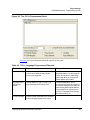
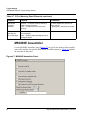
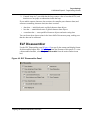
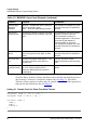
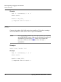
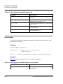
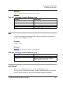
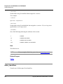
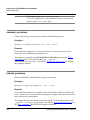
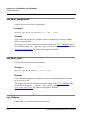
M56800E Assembler
Use the M56800E Assembler panel (Figure 4.7) to specify the format of the assembly
source files and the code that the DSP56800E assembler generates. Table 4.8 explains
the elements of this panel.
Figure 4.7 M56800E Assembler Panel
54
Targeting MC56F83xx/DSP5685x Controllers
Target Settings
DSP56800E-Specific Target Settings Panels
Table 4.8 M56800E Assembler Panel Elements
Element
Purpose
Comments
Generate Listing
File checkbox
Checked — Assembler generates a listing
file during IDE assembly of source files.
Clear — Assembler does not generate a
listing file.
A listing file contains the source file
with line numbers, relocation
information, and macro expansions.
The filename extension is .lst.
Expand Macros
in Listing
checkbox
Checked — Assembler macros expand in
the assembler listing.
Clear — Assembler macros do not expand.
This checkbox is available only if the
Generate Listing File checkbox is
checked.
Assert NOPs on
pipeline conflicts
checkbox
Checked — Assembler automatically
resolves pipeline conflicts by inserting
NOPs.
Clear — Assembler does not insert NOPs;
it reports pipeline conflicts in error
messages.
Emit Warnings
for NOP
Assertions
checkbox
Checked — Assembler issues a warning
any time it inserts a NOP to prevent a
pipeline conflict.
Clear — Assembler does not issue such
warnings.
This checkbox is available only if the
Assert NOPs on pipeline conflicts
checkbox is checked.
Emit Warnings
for Hardware
Stalls checkbox
Checked — Assembler warns that a
hardware stall will occur upon execution.
Clear — Assembler does not issue such
warnings.
This option helps optimize the cycle
count.
Allow legacy
instructions
checkbox
Checked — Assembler permits legacy
DSP56800 instruction syntax.
Clear — Assembler does not permit this
legacy syntax.
Selecting this option sets the Default
Data Memory Model and Default
Program Memory Model values to 16
bits.
Pad Pipeline for
Debugger
checkbox
Checked — Mandatory for using the
debugger. Inserts NOPs after certain
branch instructions to make breakpoints
work reliably.
Clear — Does not insert such NOPs.
If you select this option, you should
select the same option in the
M56800E Processor Settings panel.
Selecting this option increases code
size by 5 percent. But not selecting
this option risks nonrecovery after the
debugger comes to breakpoint
branch instructions.
Emit Warnings
for odd SP
Increment/
Decrement
checkbox
Checked — Enables assembler warnings
about instructions that could misalign the
stack frame.
Clear — Does not enable such warnings.
Targeting MC56F83xx/DSP5685x Controllers
55
Target Settings
DSP56800E-Specific Target Settings Panels
Table 4.8 M56800E Assembler Panel Elements (continued)
Element
Purpose
Comments
Default Data
Memory Model
list box
Specifies 16 or 24 bits as the default size.
Factory setting: 16 bits.
Default Program
Memory Model
list box
Specifies 16, 19, or 21 bits as the default
size.
Factory setting: 19 bits.
Prefix File text
box
Specifies a file to be included at the
beginning of every assembly file of the
project.
Lets you include common definitions
without using an include directive in
every file.
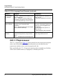
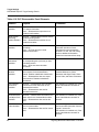
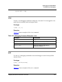
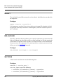
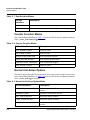
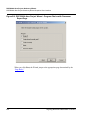
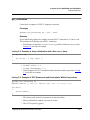
M56800E Processor
Use the M56800E Processor panel (Figure 4.8) to specify the kind of code the
compiler creates. This panel is available only if the current build target uses the
M56800E Linker. Table 4.9 explains the elements of this panel.
Figure 4.8 M56800E Processor Panel
56
Targeting MC56F83xx/DSP5685x Controllers
Target Settings
DSP56800E-Specific Target Settings Panels
Table 4.9 M56800E Processor Panel Elements
Element
Purpose
Comments
Hardware DO
Loops list box
Specifies the level of hardware DO loops:
If hardware DO loops are enabled,
debugging will be inconsistent about
stepping into loops.
Test immediately after this table
contains additional Do-loop
information.
• No Do Loops — Compiler does not
generate any
• No Nest DO Loops — Compiler
generates hardware DO loops, but
does not nest them
• Nested DO Loops — Compiler
generates hardware Do loops,
nesting them two deep.
Small Program
Model checkbox
Checked — Compiler generates a more
efficient switch table, provided that code fits
into the range 0x0—0xFFFF
Clear — Compiler generates an ordinary
switch table.
Do not check this checkbox unless
the entire program code fits into the
0x0—0xFFFF memory range.
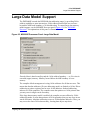
Large Data
Model checkbox
Checked — Extends DSP56800E
addressing range by providing 24-bit
address capability to instructions
Clear — Does not extend address range
24-bit address modes allow access
beyond the 64K-byte boundary of 16bit addressing.
Globals live in
lower memory
checkbox
Checked — Compiler uses 24-bit
addressing for pointer and stack
operations, 16-bit addressing for access to
global and static data.
Clear — Compiler uses 24-bit addressing
for all data access.
This checkbox is available only if the
Large Data Model checkbox is
checked.
Pad pipeline for
debugger
checkbox
Checked — Mandatory for using the
debugger. Inserts NOPs after certain
branch instructions to make breakpoints
work reliably.
Clear — Does not insert such NOPs.
If you select this option, you should
select the same option in the
M56800E Assembler panel. Selecting
this option increases code size by 5
percent. But not selectins this option
risks nonrecovery after the debugger
comes to breakpoint branch
instructions.
Emit separate
character data
section
checkbox
Checked — Compiler breaks out all
character data, placing it in appropriate
data sections (.data.char, .bss.char, or
.const.data.char).
Clear — Compiler does not break out this
data.
See additional information
immediately after this table.
Targeting MC56F83xx/DSP5685x Controllers
57
Target Settings
DSP56800E-Specific Target Settings Panels
Table 4.9 M56800E Processor Panel Elements (continued)
Element
Purpose
Comments
Zero-initialized
globals live in
data instead of
BSS checkbox
Checked — Globals initialized to zero
reside in the .data section.
Clear — Globals initialized to zero reside in
the .bss section.
Create Assembly
Output checkbox
Checked — Assembler generates
assembly code for each C file.
Clear — Assembler does not generate
assembly code for each C file.
The pragma #asmoutput overrides
this option for individual files.
Pipeline Conflict
Detection Inline
ASM list box
Specifies pipeline conflict detection during
compiling of inline assembly source code:
For more information about pipeline
conflicts, see the explanations of
pragmas check_c_src_pipeline and
check_inline_asm_pipeline.
• Not Detected — compiler does not
check for conflicts
• Conflict error — compiler issues
error messages if it detects
conflicts
• Conflict Error/Hardware Stall
Warning — compiler issues error
messages if it detects conflicts,
warnings if it detects hardware
stalls
Pipeline Conflict
Detection C
Language list
box
Specifies pipeline conflict detection during
compiling of C source code:
• Not Detected — compiler does not
check for conflicts
• Conflict error — compiler issues
error messages if it detects
conflicts
For more information about pipeline
conflicts, see the explanations of
pragmas check_c_src_pipeline and
check_inline_asm_pipeline.
The compiler generates hardware DO loops for two situations:
1. Aggregate (array and structure) initializations, and for struct copy, under any of
these conditions:
• The aggregate is byte aligned, and the aggregate size is greater than four bytes.
• The aggregate is word aligned, and the aggregate size is greater than four
words.
• The aggregate is long aligned, the aggregate size is greater than eight words,
and the Global Optimizations panel specifies Optimize for Smaller Code Size.
• The aggregate is long aligned, the aggregate size is greater than 32 words, and
the Global Optimizations panel specifies Optimize for Faster Execution.
58
Targeting MC56F83xx/DSP5685x Controllers
Target Settings
DSP56800E-Specific Target Settings Panels
2. Counted loops in C, provided that the loop counter value is less than 65536, and
that there are no jumps to subroutines inside the loop.
If you enable separate character data sections, the compiler puts character data (and
structures containing character data) into these sections:
• .data.char — initialized static or global character data objects
• .bss.char — uninitialized static or global character data objects
• .const.data.char — const qualified character objects and static string data
You can locate these data sections in the lower half of the memory map, making sure
that the data can be addressed.
ELF Disassembler
Use the ELF Disassembler panel (Figure 4.9) to specify the content and display format
for disassembled object files. Table 4.10 explains the elements of this panel. (To view
a disassembled module, select Project>Disassemble from the main-window menu
bar.)
Figure 4.9 ELF Disassembler Panel
Targeting MC56F83xx/DSP5685x Controllers
59
Target Settings
DSP56800E-Specific Target Settings Panels
Table 4.10 ELF Disassembler Panel Elements
Element
Purpose
Show Headers
checkbox
Checked — Disassembled output includes
ELF header information.
Clear — Disassembled output does not
include this information.
Show Symbol
and String
Tables checkbox
Checked — Disassembled modules include
symbol and string tables.
Clear — Disassembled modules do not
include these tables.
Verbose Info
checkbox
Checked — ELF file includes additional
information.
Clear — ELF file does not include
additional information.
Show
Relocations
checkbox
Checked — Shows relocation information
for corresponding text (.rela.text) or data
(.rela.data) section.
Clear — Does not show relocation
information.
Show Code
Modules
checkbox
Checked — Disassembler outputs ELF
code sections for the disassembled
module. Enables subordinate checkboxes.
Clear — Disassembler does not output
these sections. Disables subordinate
checkboxes.
Subordinate checkboxes are Use
Extended Mnemonics, Show
Addresses and Object Code, Show
Source Code, and Show Comments.
Use Extended
Mnemonics
checkbox
Checked — Disassembler lists extended
mnemonics for each instruction of the
disassembled module.
Clear — Disassembler does not list
extended mnemonics.
This checkbox is available only if the
Show Code Modules checkbox is
checked.
Show Addresses
and Object Code
checkbox
Checked — Disassembler lists address and
object code for the disassembled module.
Clear — Disassembler does not list this
code.
This checkbox is available only if the
Show Code Modules checkbox is
checked.
Show Source
Code checkbox
Checked — Disassembler lists source code
for the current module.
Clear — Disassembler does not list source
code.
Source code appears in mixed mode,
with line-number information from the
original C source file.
This checkbox is available only if the
Show Code Modules checkbox is
checked.
60
Comments
For the .symtab section, additional
information includes numeric
equivalents for some descriptive
constants. For the .line and .debug
sections, additional information
includes an unstructured hex dump.
Targeting MC56F83xx/DSP5685x Controllers
Target Settings
DSP56800E-Specific Target Settings Panels
Table 4.10 ELF Disassembler Panel Elements (continued)
Element
Purpose
Comments
Show Comments
checkbox
Checked — Disassembler comments
appear in sections that have comment
columns.
Clear — Disassembler does not produce
comments.
This checkbox is available only if the
Show Code Modules checkbox is
checked.
Show Data
Modules
checkbox
Checked — Disassembler outputs ELF
data sections, such as .data and .bss, for
the disassembled module.
Clear — Disassembler does not output ELF
data sections.
Disassemble
Exception Table
checkbox
Leave clear.
Show Debug
Info checkbox
Checked — Disassembler includes
DWARF symbol information in output.
Clear — Disassembler does not include this
information in output.
Does not apply to C.
M56800E Linker
Use the M56800E Linker panel (Figure 4.10) to specify linker behavior of the linker.
(This panel is only available if the current build target uses the M56800E Linker.)
Table 4.11 explains the elements of this panel.
Targeting MC56F83xx/DSP5685x Controllers
61
Target Settings
DSP56800E-Specific Target Settings Panels
Figure 4.10 M56800E Linker Panel
Table 4.11 M56800E Linker Panel Elements
Element
Purpose
Comments
Generate
Symbolic Info
checkbox
Checked — Linker generates debugging
information, within the linked ELF file.
Clear — Linker does not generate
debugging information.
If you select Project>Debug from the
main-window menu bar, the IDE
automatically enables this option.
Clearing this checkbox prevents you
from using the CodeWarrior
debugger on your project; it also
disables the subordinate Store Full
Path Names checkbox.
Store Full Path
Names
checkbox
Checked — Linker includes full path names
for source files. (Default)
Clear — Linker uses only file names.
This checkbox is available only if the
Generate Symbolic Info checkbox is
checked.
Generate Link
Map checkbox
Checked — Linker generates a link map.
Enables subordinate checkboxes List
Unused Objects, Show Transitive Closure,
and Annotate Byte Symbols.
Clear — Linker does not generate a link
map.
A link map shows which file provided
the definition of each object and
function, the address of each object
and function, a memory map of
section locations, and values of
linker-generated symbols. It also lists
unused but unstripped symbols.
62
Targeting MC56F83xx/DSP5685x Controllers
Target Settings
DSP56800E-Specific Target Settings Panels
Table 4.11 M56800E Linker Panel Elements (continued)
Element
Purpose
Comments
List Unused
Objects
checkbox
Checked — Linker includes unused objects
in the link map.
Clear — Linker does not include unused
objects in the link map.
This checkbox is available only if the
Generate Link Map checkbox is
checked.
Show Transitive
Closure
checkbox
Checked — Link map includes a list of all
objects that main( ) references.
Clear — Link map does not include this list.
Text after this table includes an
example list.
This checkbox is available only if the
Generate Link Map checkbox is
checked.
Annotate Byte
Symbols
Checked — Linker includes B annotation
for byte data types (e.g., char) in the Linker
Command File.
Clear — By default, the Linker does not
include the B annotation in the Linker
Command File. Everything without the B
annotation is a word address.
For an example of the Linker
Command File with and without the B
annotation, see Listing 4.3.
Disable
Deadstripping
checkbox
Checked — Prevents the linker from
stripping unused code or data.
Clear — Lets the linker deadstrip.
Generate ELF
Symbol Table
checkbox
Checked — Linker includes and ELF
symbol table and relocation list in the ELF
executable file.
Clear — Linker does not include these
items in the ELF executable file.
Suppress
Warning
Messages
checkbox
Checked — Linker does not display
warnings in the message window.
Clear — Linker displays warnings in the
message window.
Generate SRecord File
checkbox
Checked — Linker generates an output file
in S-record format. Activates subordinate
checkboxes.
Clear — Linker does not generate an Srecord file.
For the DSP56800E, this option
outputs three S-record files: .s (both
P and X memory contents), .p (P
memory contents), and .x (X memory
contents). The linker puts S-record
files in the output folder (a sub-folder
of the project folder.)
Sort By Address
checkbox
Checked — Enables the compiler to use
byte addresses to sort type S3 S-records
that the linker generates.
Clear — Does not enable byte-address
sorting.
This checkbox is available only if the
Generate S-Record File checkbox is
checked.
Targeting MC56F83xx/DSP5685x Controllers
63
Target Settings
DSP56800E-Specific Target Settings Panels
Table 4.11 M56800E Linker Panel Elements (continued)
Element
Purpose
Comments
Generate Byte
Addresses
checkbox
Checked — Enables the linker to generate
type S3 S-records in bytes.
Clear — Does not enable byte generation.
This checkbox is available only if the
Generate S-Record File checkbox is
checked.
Max Record
Length text box
Specifies the maximum length of type S3 Srecords that the linker generates, up to 256
bytes.
The CodeWarrior debugger handles
256-byte S-records. If you use
different software to load your
embedded application, This text box
should specify that software’s
maximum length for S-records.
This checkbox is available only if the
Generate S-Record File checkbox is
checked.
EOL Character
list box
Specifies the end-of-line character for the
type S3 S-record file: Mac, DOS, or UNIX
format.
This checkbox is available only if the
Generate S-Record File checkbox is
checked.
Entry Point text
box
Specifies the program starting point — the
first function the linker uses when the
program runs.
Text after this table includes
additional information about the entry
point.
Force Active
Symbols text box
Directs the linker to include symbols in the
link, even if those symbols are not
referenced. Makes symbols immune to
deadstripping.
Separate multiple symbols with single
spaces.
Check the Show Transitive Closure checkbox to have the link map include the list of
objects main( ) references. Consider the sample code of Listing 4.1. If the Show
Transitive Closure option is in effect and you compile this code, the linker generates a
link map file that includes the list of Listing 4.2.
Listing 4.1 Sample Code for Show Transitive Closure
void foot( void ){ int a = 100; }
void pad( void ){ int b = 101; }
int main( void ){
foot();
pad();
return 1;
}
64
Targeting MC56F83xx/DSP5685x Controllers
Target Settings
DSP56800E-Specific Target Settings Panels
Listing 4.2 Link Map File: List of main( ) references
# Link map of Finit_sim_
1] interrupt_vectors.text found in 56800E_vector.asm
2] sim_intRoutine (notype,local) found in 56800E_vector.asm
2] Finit_sim_ (func,global) found in 56800E_init.asm
3] Fmain (func,global) found in M56800E_main.c
4] Ffoot (func,global) found in M56800E_main.c
4] Fpad (func,global) found in M56800E_main.c
3] F__init_sections (func,global) found in Runtime 56800E.lib
initsections.o
4] Fmemset (func,global) found in MSL C 56800E.lib mem.o
5] F__fill_mem (func,global) found in MSL C 56800E.lib
mem_funcs.o
1] Finit_sim_ (func,global) found in 56800E_init.asm
Use the Entry Point text box to specify the starting point for a program. The default
function this text box names is in the startup code that sets up the DSP56800E
environment before your code executes. This function and its corresponding startup
code depend on your stationery selection.
For hardware-targeted stationery, the startup code is on the path:
support\<name of hardware, e.g., M56852E>\startup
For simulator-targeted stationery, the startup code is on the path:
support\M56800E\init
The startup code performs such additional tasks as clearing the hardware stack,
creating an interrupt table, and getting the addresses for the stack start and exception
handler. The final task for the startup code is call your main() function.
Check the Annotate Byte Symbols checkbox to have the link map include the B
annotation for byte addresses and no B annotation for word addresses (Listing 4.3).
Listing 4.3 Example of Annotate Byte Symbols
int myint;
char mychar;
B 0000049C 00000001 .bss Fmychar (main.c)
0000024F 00000001 .bss Fmyint (main.c)
Targeting MC56F83xx/DSP5685x Controllers
65
Target Settings
DSP56800E-Specific Target Settings Panels
Remote Debugging
Use the Remote Debugging panel (Figure 4.11, Figure 4.12) to set parameters for
communication between a DSP56800E board or Simulator and the CodeWarrior
DSP56800E debugger. Table 4.12 explains the elements of this panel.
NOTE
Communications specifications also involve settings of the
debugging M56800E Target panel (Figure 4.13).
Figure 4.11 Remote Debugging Panel (56800E Simulator)
Figure 4.12 Remote Debugging Panel (56800E Local Connection)
66
Targeting MC56F83xx/DSP5685x Controllers
Target Settings
DSP56800E-Specific Target Settings Panels
Table 4.12 Remote Debugging Panel Elements
Element
Purpose
Comments
Connection list
box
Specifies the connection type:
Selecting 56800E Simulator keeps
the panel as Figure 4.11 shows.
Selecting Local Hardware
Connection adds the JTAG Clock
Speed text box to the panel, as
Figure 4.12 shows.
• 56800E Simulator — appropriate
for testing code on the simulator
before downloading code to an
actual board.
• 56800E Local Hardware
Connection (CSS) — appropriate
for using your computer’s
command converter server,
connected to a DSP56800E board.
Remote
Download Path
text box
Not supported at this time.
Launch Remote
Host Application
checkbox
Not supported at this time.
JTAG Clock
Speed text box
Specifies the JTAG lock speed for local
hardware connection. (Default is 8000
kilohertz.)
This list box is available only if the
Connection list box specifies Local
Hardware Connection (CSS).
M56800E Target (Debugging)
Use the debugging M56800E Target panel (Figure 4.13) to set parameters for
communication between a DSP56800E board or Simulator and the CodeWarrior
DSP56800E debugger. Table 4.12 explains the elements of this panel.
NOTE
Communications specifications also involve settings of the Remote
Debugging panel (Figure 4.11, Figure 4.12).
Auto-clear previous breakpoint on new breakpoint
request
This option is only available when you enable the Use hardware breakpoints option.
When you also enable the Auto-clear previous hardware breakpoint and set a
breakpoint, the original breakpoint is automatically cleared and the new breakpoint is
immediately set. If you disable the Auto-clear previous hardware breakpoint option
and attempt to set another breakpoint, you will be prompted the following message:
Targeting MC56F83xx/DSP5685x Controllers
67
Target Settings
DSP56800E-Specific Target Settings Panels
If you click the Yes button, the previous breakpoint is cleared and the new breakpoint
is set.
If you click the Yes to all button, the Auto-clear previous hardware breakpoint option is
enabled and the previously set breakpoint is cleared out without prompting for every
subsequent occurrence.
If you click the No button, the previous breakpoint is kept and the new breakpoint
request is ignored.
Figure 4.13 Debugging M56800E Target Panel
68
Targeting MC56F83xx/DSP5685x Controllers
Target Settings
DSP56800E-Specific Target Settings Panels
Table 4.13 Debugging M56800E Target Panel Elements
Element
Purpose
Always reset on
download
checkbox
Checked — IDE issues a reset to the target
board each time you connect to the board.
Clear — IDE does not issue a reset each
time you connect to the target board.
Use initialization
file checkbox
Checked — After a reset, the IDE uses an
optional hardware initialization file before
downloading code.
Clear — IDE does not use a hardware
initialization file.
The Use initialization file text box
specifies the file.
Text immediately after this table gives
more information about initialization
files.
Use initialization
file text box
Specifies the initialization file.
Applicable only if the Use initialization
file checkbox is checked.
Breakpoint Mode
checkbox
Specifies the breakpoint mode:
Software breakpoints contain debug
instructions that the debugger writes
into your code. You cannot set such
breakpoints in flash, as it is read-only.
Hardware breakpoints use the onchip debugging capabilities of the
DSP56800E. The number of
available hardware breakpoints limits
these capabilities.
Note, Breakpoint Mode only effects
HW targets.
• Automatic — CodeWarrior
software determines when to use
software or hardware breakpoints.
• Software — CodeWarrior software
always uses software breakpoints.
• Hardware — CodeWarrior software
always uses the available
hardware breakpoints.
Auto-clear
previous
hardware
breakpoint
Comments
Checked — Automatically clears the
previous harware breakpoint.
Clear — Does not Automatically clears the
previous harware breakpoint.
An initialization file consists of text instructions telling the debugger how to initialize
the hardware after reset, but before downloading code. You can use initialization file
commands to assign values to registers and memory locations, and to set up flash
memory parameters.
The initialization files of your IDE are on the path:
{CodeWarrior path}\M56800E Support\initialization
The name of each initialization file includes the number of the corresponding
processor, such as 568345. Each file with “_ext” enables the processor’s external
memory. If the processor has Flash memory, the initialization file with “_flash”
enables both Flash and external memory.
To set up an initialization file:
Targeting MC56F83xx/DSP5685x Controllers
69
Target Settings
DSP56800E-Specific Target Settings Panels
1. In the debugging M56800E Target panel, check the Use initialization file
checkbox.
2. Specify the name of the initialization file, per either substep a or b:
a. Type the name in the Use initialization file text box. If the name is not a full
pathname, the debugger searches for the file in the project directory. If the file
is not in this directory, the debugger searches on the path:
{CodeWarrior path}\M56800E Support\ initialization
directory.
b. Click the Choose button; the Choose file dialog box appears. Navigate to the
appropriate file. When you select the file, the system puts its name in the Use
initialization file text box.
Each text line of a command file begins with a command or the comment symbol #.
The system ignores comment lines, as well as blank lines.
Table 4.14 lists the supported commands and their arguments. For a more detailed
description of the Flash Memory commands see “Flash Memory Commands.”
Table 4.14 Initialization File Commands and Arguments
Command
Arguments
Description
writepmem
<addr> <value>
Writes a 16-bit value to the
specified P: Memory location.
writexmem
<addr> <value>
Writes a 16-bit value to the
specified X: Memory location.
writereg
<regName> <value>
Writes a 16-bit value to the
specified register.
set_hfmclkd
<value>
Writes the flash memory’s clock
divider value to the hfmclkd
register
set_hfm_base
<address>
Sets the address of hfm_base.
This is the map location of the
flash memory control registers
in X: Memory.
add_hfm_unit
<startAddr><endAddr>
<bank><numSectors>
<pageSize><progMem>
<boot><interleaved>
Adds a flash memory unit to the
list and sets its parameter
values.
70
Targeting MC56F83xx/DSP5685x Controllers
Target Settings
DSP56800E-Specific Target Settings Panels
Table 4.14 Initialization File Commands and Arguments (continued)
Command
Arguments
Description
set_hfm_programmer_base
<address>
Specifies the address where
the onboard flash programmer
will be loaded in P: Memory.
set_hfm_prog_buffer_base
<address>
Specifies where the data to be
programmed will be loaded in
X: Memory.
set_hfm_prog_buffer_size
<size>
Specifies the size of the buffer
in X: Memory which will hold the
data to be programmed.
set_hfm_erase_mode
<units | pages | all>
Sets the erase mode.
set_hfm_verify_erase
<1 | 0>
Sets the flash memory erase
verification mode.
set_hfm_verify_program
<1 | 0>
Sets the flash program
verification mode.
unlock_flash_on_connect
<1 | 0>
Unlocks and erases flash
memory immediately upon
connection.
Remote Debug Options
Use the Remote Debug Options panel (Figure 4.14) to specify different remote debug
options. explains the elements of this panel.
Targeting MC56F83xx/DSP5685x Controllers
71
Target Settings
DSP56800E-Specific Target Settings Panels
Figure 4.14 Remote Debug Options
72
Targeting MC56F83xx/DSP5685x Controllers
Target Settings
DSP56800E-Specific Target Settings Panels
Table 4.15 Remote Debug Options Panel Elements
Element
Purpose
Comments
Program
Download
Options area
Checked Download checkboxes specify the
section types to be downloaded on initial
launch and on successive runs.
Checked Verify checkboxes specify the
section types to be verified (that is, read
back to the linker).
Section types:
• Executable — program-code
sections that have X flags in
the linker command file.
• Constant Data — programdata sections that do not
have X or W flags in the
linker command file.
• Initialized Data — programdata sections with initial
values. These sections have
W flags, but not X flags, in
the linker command file.
• Uninitialized Data —
program-data sections
without initial values. These
sections have W flags, but
not X flags, in the linker
command file.
Use Memory
Configuration
File checkbox
Targeting MC56F83xx/DSP5685x Controllers
Not supported at this time.
73
Target Settings
DSP56800E-Specific Target Settings Panels
74
Targeting MC56F83xx/DSP5685x Controllers
5
Processor Expert Interface
Your CodeWarrior™ IDE features a Processor Expert™ plug-in interface, for rapid
development of embedded applications. This chapter explains Processor Expert
concepts, and Processor Expert additions to the CodeWarrior visual interface. This
chapter includes a brief tutorial exercise.
This chapter contains these sections:
• Processor Expert Overview
• Processor Expert Windows
• Processor Expert Tutorial
Processor Expert Overview
The Processor Expert Interface (PEI) is an integrated development environment for
applications based on DSP56800/E (or many other) embedded microcontrollers. It
reduces development time and cost for applications. Its code makes very efficient use
of microcontroller and peripheral capabilities. Furthermore, it helps develop code that
is highly portable.
Features include:
• Embedded Beans™ components — Each bean encapsulates a basic
functionality of embedded systems, such as CPU core, CPU on-chip peripherals,
and virtual devices. To create an application, you select, modify, and combine the
appropriate beans.
– The Bean Selector window lists all available beans, in an expandable tree
structure. The Bean Selector describes each bean; some descriptions are
extensive.
– The Bean Inspector window lets you modify bean properties, methods,
events, and comments.
• Processor Expert page — This additional page for the CodeWarrior project
window lists project CPUs, beans, and modules, in a tree structure. Selecting or
double-clicking items of the page opens or changes the contents of related
Processor Expert windows.
Targeting MC56F83xx/DSP5685x Controllers
75
Processor Expert Interface
Processor Expert Overview
• Target CPU window — This window depicts the target microprocessor as a
simple package or a package with peripherals. As you move the cursor over this
picture’s pins, the window shows pin numbers and signals. Additionally, you can
have this window show a scrollable block diagram of the microprocessor.
• CPU Structure window — This window shows the relationships of all targetmicroprocessor elements, in an expandable-tree representation.
• CPU Types Overview — This reference window lists all CPUs that your
Processor Expert version supports.
• Memory Map — This window shows the CPU address space, plus mapping for
internal and external memory.
• Resource Meter — This window shows the resource allocation for the target
microprocessor.
• Peripheral Usage Inspector — This window shows which bean allocates each
on-chip peripheral.
• Installed Beans Overview — This reference window provides information
about all installed beans in your Processor Expert version.
• Driver generation — The PEI suggests, connects, and generates driver code for
embedded-system hardware, peripherals, and algorithms.
• Top-Down Design — A developer starts design by defining application
behavior, rather than by focussing on how the microcontroller works.
• Extensible beans library — This library supports many microprocessors,
peripherals, and virtual devices.
• Beans wizard — This external tool helps developers create their own custom
beans.
• Extensive help information — You access this information either by selecting
Help from the Program Expert menu, or by clicking the Help button of any
Processor Expert window or dialog box.
Processor Expert Code Generation
The PEI manages your CPU and other hardware resources, so that you can concentrate
on virtual prototyping and design. Your steps for application development are:
1. Creating a CodeWarrior project, specifying the Processor Expert stationery
appropriate for your target processor.
2. Configuring the appropriate CPU bean.
3. Selecting and configuring the appropriate function beans.
76
Targeting MC56F83xx/DSP5685x Controllers
Processor Expert Interface
Processor Expert Overview
4. Starting code design (that is, building the application).
As you create the project, the project window opens in the IDE main window. This
project window has a Processor Expert page (Figure 5.1). The Processor Expert Target
CPU window also appears at this time. So does the Processor Expert bean selector
window, although it is behind the Target CPU window.
Figure 5.1 Project Window: Processor Expert Page
When you start code design, the PEI generates commented code from the bean
settings. This code generation takes advantage of the Processor Expert CPU
knowledge system and solution bank, which consists of hand-written, tested code
optimized for efficiency.
To add new functionalities, you select and configure additional beans, then restart
code design. Another straightforward expansion of PEI code is combining other code
that you already had produced with different tools.
Targeting MC56F83xx/DSP5685x Controllers
77
Processor Expert Interface
Processor Expert Overview
Processor Expert Beans
Beans encapsulate the most-required functionalities for embedded applications.
Examples include port bit operations, interrupts, communication timers, and A/D
converters.
The Bean Selector (Figure 5.2) helps you find appropriate beans by category:
processor, MCU external devices, MCU internal peripherals, or on-chip peripherals.
To open he bean selector, select Processor Expert > View > Bean Selector, from the
main-window menu bar.
Figure 5.2 Bean Selector
The bean selector’s tree structures list all available beans; double-clicking the name
adds the bean to your project. Clicking the Quick Help button opens or closes an
explanation pane that describes the highlighted bean.
Once you determine the appropriate beans, you use the Bean Inspector (Figure 5.3) to
fine tune each bean, making it optimal for your application.
78
Targeting MC56F83xx/DSP5685x Controllers
Processor Expert Interface
Processor Expert Overview
Figure 5.3 Bean Inspector
Using the Bean Inspector to set a bean’s initialization properties automatically adds
bean initialization code to CPU initialization code. You use the Bean Inspector to
adjust bean properties, so that generated code is optimal for your application.
Beans greatly facilitate management of on-chip peripherals. When you choose a
peripheral from bean properties, the PEI presents all possible candidates. But the PEI
indicates which candidates already are allocated, and which are not compatible with
current bean settings.
Processor Expert Menu
Table 5.1 explains the selections of the Processor Expert menu.
Targeting MC56F83xx/DSP5685x Controllers
79
Processor Expert Interface
Processor Expert Overview
Table 5.1 Processor Expert Menu Selections
Item
Subitem
Action
Open Processor
Expert
none
Opens the PEI for the current project.
(Available only if the current project does not
already involve the PEI.)
Code Design
<Project>
none
Generates code, including drivers, for the
current project. Access these files via the
Generate Code folder, of the project-window
Files page.
Undo Last Code
Design
none
Deletes the most recently-generated code,
returning project files to their state after the
previous, error-free code generation.
View
Project Panel
Brings the Processor Expert page to the front of
the CodeWarrior project window.
(Not available if the project window does not
include a Processor Expert page.)
Bean Inspector
Opens the Bean Inspector window, which gives
you access to bean properties.
Bean Selector
Opens the Beans Selector window, which you
use to choose the most appropriate beans.
Target CPU Package
Opens the Target CPU Package window, which
depicts the processor. As you move your cursor
over the pins of this picture, text boxes show pin
numbers and signal names.
Target CPU Block Diagram
Opens the Target CPU Package window, but
portrays the processor as a large block diagram.
Scroll bars let you view any part of the diagram.
As you move your cursor over modules, floating
text boxes identify pin numbers and signals.
Error Window
Opens the Error Window, which shows hints,
warnings, and error messages.
Resource Meter
Opens the Resource Meter window, which
shows usage and availability of processor
resources.
Target CPU Structure
Opens the CPU Structure window, which uses
an expandible tree structure to portray the
processor.
View (continued)
80
Targeting MC56F83xx/DSP5685x Controllers
Processor Expert Interface
Processor Expert Overview
Table 5.1 Processor Expert Menu Selections (continued)
Item
Tools
Help
Help (continued)
Subitem
Action
Peripherals Usage
Inspector
Opens the Peripherals Usage Inspector window,
which shows which bean allocates each
peripheral.
Peripheral Initialization
Inspector
Opens the Peripherals Initialization Inspector
window, which show the initialization value and
value after reset for all peripheral register bits.
Installed Beans Overview
Opens the Beans Overview window, which
provides information about all beans in your
project.
CPU Types Overview
Opens the CPU Overview window, which lists
supported processors in an expandable tree
structure.
CPU Parameters Overview
Opens the CPU Parameters window, which lists
clock-speed ranges, number of pins, number of
timers, and other reference information for the
supported processors.
Memory Map
Opens the Memory Map window, which depicts
CPU address space, internal memory, and
external memory.
<tool name>
Starts the specified compiler, linker or other tool.
(You use the Tools Setup window to add tool
names to this menu.)
SHELL
Opens a command-line window.
Tools Setup
Opens the Tools Setup window, which you use
to add tools to this menu.
Processor Expert Help
Opens the help start page.
Introduction
Opens the PEI help introduction.
Benefits
Opens an explanation of PEI benefits.
User Interface
Opens an explanation of the PEI environment.
Tutorial
[None available for the DSP56800/E.]
Quick Start
Opens PEI quick start instructions.
Embedded Beans
Opens the first page of a description database of
all beans.
Targeting MC56F83xx/DSP5685x Controllers
81
Processor Expert Interface
Processor Expert Overview
Table 5.1 Processor Expert Menu Selections (continued)
Item
Subitem
Action
Embedded Beans
Categories
Opens the first page of a description database of
beans, organized by category.
Supported CPUs,
Compilers, and Debuggers
Opens the list of processors and tools that the
PEI plug-in supports.
PESL Library User Manual
Opens the Processor Expert System Library, for
advanced developers.
User Guide
Opens a .pdf guide that focuses on the
DSP56800/E processor family.
Search in PDF
Documentation of the
Target CPU
Opens documentation of the target processor, in
a .pdf search window.
Go to Processor Expert
Home Page
Opens your default browser, taking you to the
PEI home page.
About Processor Expert
Opens a standard About dialog box for the PEI.
Update Processor Exert
Beans from Package
Opens the Open Update Package window. You
can use this file-selection window to add
updated or new beans (which you downloaded
over the web) to your project.
Check Processor Expert
Web for updates
Checks for updates available over the web. If
any are available, opens your default browser,
so that you can download them.
Bring PE Windows to
Front
none
Moves PEI windows to the front of your monitor
screen.
Arrange PE Windows
none
Restores the default arrangement of all open
PEI windows.
Update
82
Targeting MC56F83xx/DSP5685x Controllers
Processor Expert Interface
Processor Expert Windows
Processor Expert Windows
This section illustrates important Processor Expert windows and dialog boxes.
Bean Selector
The Bean Selector window (Figure 5.4) explains which beans are available, helping
you identify those most appropriate for your application project. To open this window,
select Processor Expert > View > Bean Selector, from the main-window menu bar.
Figure 5.4 Bean Selector Window
The Bean Categories page, at the left side of this window, lists the available beans in
category order, in an expandable tree structure. Green string bean symbols identify
beans that have available licenses. Grey string bean symbols identify beans that do not
have available licenses.
The On-Chip Peripherals page lists beans available for specific peripherals, also in
an expandable tree structure. Yellow folder symbols identify peripherals fully
available. Light blue folder symbols identify partially used peripherals. Dark blue
folder symbols identify fully used peripherals.
Bean names are black; bean template names are blue. Double-click a bean name to add
it to your project.
Click the Quick Help button to add the explanation pane to the right side of the
window, as Figure 5.4 shows. This pane describes the selected (highlighted) bean. Use
the scroll bars to read descriptions that are long.
Targeting MC56F83xx/DSP5685x Controllers
83
Processor Expert Interface
Processor Expert Windows
Click the two buttons at the bottom of the window to activate or deactivate filters. If
the all/CPU filter is active, the window lists only the beans for the target CPU. If the
license filter is active, the window lists only the beans for which licenses are available.
Bean Inspector
The Bean Inspector window (Figure 5.5) lets you modify bean properties and other
settings. To open this window, select Processor Expert > View > Bean Inspector,
from the main-window menu bar.
Figure 5.5 Bean Inspector Window
This window shows information about the currently selected bean — that is, the
highlighted bean name in the project-window Processor Expert page. The title of the
Bean Inspector window includes the bean name.
The Bean Inspector consists of Properties, Methods, Events, and Comment pages. The
first three pages have these columns:
84
Targeting MC56F83xx/DSP5685x Controllers
Processor Expert Interface
Processor Expert Windows
• Item names — Items to be set. Double-click on group names to expand or
collapse this list. For the Method or Event page, double-clicking on an item may
open the file editor, at the corresponding code location.
• Selected settings — Possible settings for your application. To change any ON/
OFF-type setting, click the circular-arrow button. Settings with multiple possible
values have triangle symbols: click the triangle to open a context menu, then
select the appropriate value. Timing settings have an ellipsis (...) button: click this
button to open a setting dialog box.
• Setting status — Current settings or error statuses.
Use the comments page to write any notations or comments you wish.
NOTE
If you have specified a target compiler, the Bean Inspector includes
an additional Build options page for the CPU bean.
If your project includes external peripherals, the Bean Inspector
includes an additional Used page. Clicking a circular-arrow button
reserves a resource for connection to an external device. Clicking the
same button again frees the resource.
The Basic, Advanced, and Expert view mode buttons, at the bottom of the window, let
you change the detail level of Bean Inspector information.
The Bean Inspector window has its own menu bar. Selections include restoring default
settings, saving the selected bean as a template, changing the bean’s icon,
disconnecting from the CPU, and several kinds of help information.
Targeting MC56F83xx/DSP5685x Controllers
85
Processor Expert Interface
Processor Expert Windows
Target CPU Window
The Target CPU window (Figure 5.6) depicts the target processor as a realistic CPU
package, as a CPU package with peripherals, or as a block diagram. To open this
window, select Processor Expert > View > Target CPU Package, from the mainwindow menu bar. (To have this window show the block diagram, you may select
Processor Expert > View > Target CPU Block Diagram, from the main-window
menu bar.)
Figure 5.6 Target CPU Window: Package
Arrows on pins indicate input, output, or bidirectional signals. As you move your
cursor over the processor pins, text boxes at the bottom of this window show the pin
numbers and signal names.
86
Targeting MC56F83xx/DSP5685x Controllers
Processor Expert Interface
Processor Expert Windows
Use the control buttons at the left edge of this window to modify the depiction of the
processor. One button, for example, changes the picture view the CPU package with
peripherals. However, as Figure 5.7 shows, it is not always possible for the picture of a
sophisticated processor to display internal peripherals.
Figure 5.7 Target CPU Window: Package and Peripherals
Targeting MC56F83xx/DSP5685x Controllers
87
Processor Expert Interface
Processor Expert Windows
In such a case, you can click the Always show internal peripheral devices control
button. Figure 5.8 shows that this expands the picture size, as necessary, to allow the
peripheral representations. This view also includes bean icons (blue circles) attached
to the appropriate processor pins. Use the scroll bars to view other parts of the
processor picture.
Figure 5.8 Target CPU Window: Peripherals and Bean Icons
88
Targeting MC56F83xx/DSP5685x Controllers
Processor Expert Interface
Processor Expert Windows
Click the Show MCU Block Diagram to change the picture to a block diagram, as
Figure 5.9 shows. Use the scroll bars to view other parts of the diagram. (You can
bring up the block diagram as you open the Target CPU window, by selecting
Processor Expert > View > Target CPU Block Diagram, from the main-window
menu bar.)
Figure 5.9 Target CPU Window: Block Diagram
Other control buttons at the left edge of the window let you:
• Show bean icons attached to processor pins.
• Rotate the CPU picture clockwise 90 degrees.
• Toggle default and user-defined names of pins and peripherals.
• Print the CPU picture.
Targeting MC56F83xx/DSP5685x Controllers
89
Processor Expert Interface
Processor Expert Windows
NOTE
As you move your cursor over bean icons, peripherals, and modules,
text boxes or floating hints show information such as names,
descriptions, and the allocating beans.
And note these additional mouse control actions for the Target CPU window:
• Clicking a bean icon selects the bean in the project window’s Processor Expert
page.
• Double-clicking a bean icon open the Bean Inspector, displaying information for
that bean.
• Right-clicking a bean icon, a pin, or a peripheral opens the corresponding context
menu.
• Double-clicking an ellipsis (...) bean icon opens a context menu of all beans using
parts of the peripheral. Selecting one bean from this menu opens the Bean
Inspector.
• Right-clicking an ellipsis (...) bean icon opens a context menu of all beans using
parts of the peripheral. Selecting one bean from this menu opens the bean context
menu.
90
Targeting MC56F83xx/DSP5685x Controllers
Processor Expert Interface
Processor Expert Windows
Memory Map Window
The Memory Map window (Figure 5.10) depicts CPU address space, and the map of
internal and external memory. To open this window, select Processor Expert > View
> Memory Map, from the main-window menu bar.
Figure 5.10 Memory Map Window
The color key for memory blocks is:
• White — Non-usable space
• Dark Blue — I/O space
• Medium Blue — RAM
• Light Blue — ROM
Targeting MC56F83xx/DSP5685x Controllers
91
Processor Expert Interface
Processor Expert Windows
• Cyan — FLASH memory or EEPROM
• Black — External memory.
Pause your cursor over any block of the map to bring up a brief description.
CPU Types Overview
The CPU Types Overview window (Figure 5.11) lists supported processors, in an
expandable tree structure. To open this window, select Processor Expert > View >
CPU Types Overview, from the main-window menu bar.
Figure 5.11 CPU Types Overview Window
Right-click the window to open a context menu that lets you add the selected CPU to
the project, expand the tree structure, collapse the tree structure, or get help
information.
92
Targeting MC56F83xx/DSP5685x Controllers
Processor Expert Interface
Processor Expert Windows
Resource Meter
The Resource Meter window (Figure 5.12) shows the usage or availability of
processor resources. To open this window, select Processor Expert > View >
Resource Meter, from the main-window menu bar.
Figure 5.12 Resource Meter Window
Bars of this window indicate:
• The number of pins used
• The number of ports used
• Allocation of timer compare registers
• The number of timer capture registers used
• Allocation of serial communication channels
• Allocation of A/D converter channels.
Pausing your cursor over some fields of this window brings up details of specific
resources.
Targeting MC56F83xx/DSP5685x Controllers
93
Processor Expert Interface
Processor Expert Windows
Installed Beans Overview
The Installed Beans Overview window (Figure 5.13) shows reference information
about the installed beans. To open this window, select Processor Expert > View >
Installed Beans Overview, from the main-window menu bar.
Figure 5.13 Installed Beans Overview Window
This window’s View menu lets you change the display contents, such as showing
driver status and information, restricting the kinds of beans the display covers, and so
one.
94
Targeting MC56F83xx/DSP5685x Controllers
Processor Expert Interface
Processor Expert Windows
Peripherals Usage Inspector
The Peripherals Usage window (Figure 5.14) shows which bean allocates each
peripheral. To open this window, select Processor Expert > View > Peripherals
Usage Inspector, from the main-window menu bar.
Figure 5.14 Peripherals Usage Window
The pages of this window reflect the peripheral categories: I/O, interrupts, timers, and
channels. The columns of each page list peripheral pins, signal names, and the
allocating beans.
Pausing your cursor over various parts of this window brings up brief descriptions of
items. This window’s View menu lets you expand or collapse the display.
Targeting MC56F83xx/DSP5685x Controllers
95
Processor Expert Interface
Processor Expert Tutorial
Processor Expert Tutorial
This tutorial exercise generates code that flashes the LEDs of a DSP56836E
development board. Follow these steps:
1. Create a M568346 project, using C with Processor Expert stationery.
a. Start the CodeWarrior IDE, if it is not started already.
b. From the main-window menu bar, select File > New. The New window
appears.
c. In the Project page, select (highlight) Dsp56800/E EABI Stationery.
d. In the Project name text box, enter a name for the project, such as
LEDcontrol.
e. Click the OK button. The New Project window replaces the New window.
f. In the Project Stationery list, expand the M56836E entry.
g. Select C with Processor Expert, as Figure 5.15 shows.
Figure 5.15 C with Processor Expert Selection
96
Targeting MC56F83xx/DSP5685x Controllers
Processor Expert Interface
Processor Expert Tutorial
h. Click the OK button. The IDE:
• Opens the project window, docking it the left of the main window. This
project window includes a Processor Expert page.
• Opens the Target CPU window, as Figure 5.16 shows. This window shows
the CPU package and peripherals view.
• Opens the Bean Selector window, behind the Target CPU window.
Figure 5.16 Project, Target CPU Windows
2. Select the sdm external memory target.
a. Click the project window’s Targets tab. The Targets page moves to the front
of the window.
b. Click the target icon of the sdm external memory entry. The black arrow
symbol moves to this icon, confirming your selection.
3. Add six BitIO beans to the project.
Targeting MC56F83xx/DSP5685x Controllers
97
Processor Expert Interface
Processor Expert Tutorial
a. Click the project window’s Processor Expert tab. The Processor Expert page
moves to the front of the window.
b. Make the Bean Selector window visible:
• Minimize the Target CPU window.
• Select Processor Expert > View > Bean Selector, from the main-window
menu bar.
c. In the Bean Categories page, expand the entry MCU internal peripherals.
d. Expand the subentry Port I/O.
e. Double-click the BitIO bean name six times. (Figure 5.17 depicts this bean
selection.) The IDE adds these beans to your project; new bean icons appear
in the project window’s Processor Expert page.
Figure 5.17 Bean Selector: BitIO Selection
98
Targeting MC56F83xx/DSP5685x Controllers
Processor Expert Interface
Processor Expert Tutorial
NOTE
If new bean icons do not appear in the Processor Expert page, the
system still may have added them to the project. Close the project,
then reopen it. When you bring the Processor Expert page to the front
of the project window, the page should show the new bean icons.
4. Add two ExtInt beans to the project.
a. In the Bean Categories page of the Bean Selector window, expand the
Interrupts subentry.
b. Double-click the ExtInt bean name two times. The IDE adds these beans to
your project; new bean icons appear in the Processor Expert page.
c. You may close the Bean Inspector window.
5. Rename the eight beans GPIO_C0 — GPIO_C3, GPIO_D6, GPIO_D7, IRQA,
and IRQB.
a. In the project window’s Processor Expert page, right-click the name of the
first BitIO bean. A context menu appears.
b. Select Rename Bean. A change box appears around the bean name.
Targeting MC56F83xx/DSP5685x Controllers
99
Processor Expert Interface
Processor Expert Tutorial
c. Type the new name GPIO_C0, then press the Enter key. The list shows the
new name; as Figure 5.18 shows, this name still ends with BitIO.
Figure 5.18 New Bean Name
d. Repeat substeps a, b, and c for each of the other BitIO beans, renaming them
GPIO_C1, GPIO_C2, GPIO_C3, GPIO_D6, and GPIO_D7.
100
Targeting MC56F83xx/DSP5685x Controllers
Processor Expert Interface
Processor Expert Tutorial
e. Repeat substeps a, b, and c for the two ExtInt beans, renaming them IRQA and
IRQB. (Figure 5.19 shows the Processor Expert page at this point.)
Figure 5.19 New Bean Names
6. Update pin associations for each bean.
a. In the Processor Expert page, double-click the bean name GPIO_C0. The
Bean Inspector window opens, displaying information for this bean.
b. Use standard window controls to make the middle column of the Properties
page about 2 inches wide.
c. In the Pin for I/O line, click the triangle symbol of the middle-column list
box. The list box opens.
Targeting MC56F83xx/DSP5685x Controllers
101
Processor Expert Interface
Processor Expert Tutorial
d. Use this list box to select GPIOC0_SCLK1_TB0_PHASEA1. (Figure 5.20
depicts this selection.)
Figure 5.20 New Pin Association
e. In the project window’s Processor Expert page, select the bean name
GPIO_C1. The Bean Inspector information changes accordingly.
f. Use the Pin for I/O middle-column list box to select
GPIOC1_MOSI1_TB1_PHASEB1.
g. Repeat substeps e and f, for bean GPIO_C2, to change its associated pin to
GPIOC2_MISO1_TB2_INDEX1.
h. Repeat substeps e and f, for bean GPIO_C3, to change its associated pin to
GPIOC3_SSA_B_TB3_HOME1.
i. Repeat substeps e and f, for bean GPIO_D6, to change its associated pin to
GPIOD6_TxD1.
j. Repeat substeps e and f, for bean GPIO_D7, to change its associated pin to
GPIOD7_RxD1.
k. In the project window’s Processor Expert page, select the bean name IRQA.
The Bean Inspector information changes accordingly.
l. Use the Pin middle-column list box to select IRQA_B.
m. Repeat substeps k and l, for bean IRQB, to change its associated pin to
IRQB_B.
n. You may close the Bean Inspector window.
102
Targeting MC56F83xx/DSP5685x Controllers
Processor Expert Interface
Processor Expert Tutorial
7. Enable BitIO SetDir, ClrVal, and SetVal functions.
a. In the Processor Expert page, click the plus-sign control for the GPIO_C0
bean. The function list expands: red X symbols indicate disabled functions,
green check symbols indicate enabled functions.
b. Double-click function symbols as necessary, so that only SetDir, ClrVal, and
SetVal have green checks. (Figure 5.21 shows this configuration.)
Figure 5.21 GPIO_C3 Enabled Functions
c. Click the GPIO_C0 minus-sign control. The function list collapses.
d. Repeat substeps a, b, and c for beans GPIO_C1, GPIO_C2, GPIO_C3,
GPIO_D6, and GPIO_D7.
8. Enable ExtInt OnInterrupt, GetVal functions.
a. In the Processor Expert page, click the plus-sign control for the IRQA bean.
The function list expands.
b. Double-click function symbols as necessary, so that only OnInterrupt and
GetVal have green check symbols.
c. Click the IRQA minus-sign control. The function list collapses.
d. Repeat substeps a, b, and c for bean IRQB.
9. Design (generate) project code.
a. From the main-window menu bar, select Processor Expert > Code Design
‘LEDcontrol.mcp.’ (This selection shows the actual name of your project.)
The IDE and PEI generate several new files for your project.
b. You may close all windows except the project window.
Targeting MC56F83xx/DSP5685x Controllers
103
Processor Expert Interface
Processor Expert Tutorial
10. Update file Events.c.
a. Click the project window’s Files tab. The Files page moves to the front of the
window.
b. Expand the User Modules folder.
c. Double-click filename Events.c. An editor window opens, displaying this
file’s text. (Listing 5.1, at the end of this tutorial, shows this file’s contents.)
d. Find the line IRQB_OnInterrupt().
e. Above this line, enter the new line extern short IRQB_On;.
f. Inside IRQB_OnInterrupt(), enter the new line IRQB_On ^= 1;.
g. Find the line IRQA_OnInterrupt().
h. Above this line, enter the new line extern short IRQA_On;.
i. Inside IRQA_OnInterrupt(), enter the new line IRQA_On ^= 1;.
NOTE
Listing 5.1 shows these new lines as bold italics.
j. Save and close file Events.c.
11. Update file LEDcontrol.c.
a. In the project window’s Files page, double-click filename LEDcontrol.c (or
the actual .c filename of your project). An editor window opens, displaying
this file’s text.
b. Add custom code, to utilize the beans.
NOTE
Listing 5.2 shows custom entries as bold italics. Processor Expert
software generated all other code of the file.
c. Save and close the file.
12. Build and debug the project.
a. From the main-window menu bar, select Project > Make. The IDE compiles
and links your project, generating executable code.
b. Debug your project, as you would any other CodeWarrior project.
104
Targeting MC56F83xx/DSP5685x Controllers
Processor Expert Interface
Processor Expert Tutorial
This completes the Processor Expert tutorial exercise. Downloading this code to a
DSP56836E development board should make the board LEDs flash in a distinctive
pattern.
Listing 5.1 File Events.c
/*
** ################################################################# **
**
Filename : Events.C
**
**
Project
: LEDcontrol
**
**
Processor : DSP56F836
**
**
Beantype : Events
**
**
Version
: Driver 01.00
**
**
Compiler : Metrowerks DSP C Compiler
**
**
Date/Time : 3/24/2003, 1:18 PM
**
**
Abstract :
**
**
This is user's event module.
**
Put your event handler code here.
**
**
Settings :
**
**
**
Contents :
**
**
IRQB_OnInterrupt - void IRQB_OnInterrupt(void);
**
IRQA_OnInterrupt - void IRQA_OnInterrupt(void);
**
**
**
(c) Copyright UNIS, spol. s r.o. 1997-2002
**
**
UNIS, spol. s r.o.
**
Jundrovska 33
**
624 00 Brno
**
Czech Republic
**
**
http
: www.processorexpert.com
**
mail
: [email protected]
Targeting MC56F83xx/DSP5685x Controllers
105
Processor Expert Interface
Processor Expert Tutorial
**
** #########################################################
*/
/* MODULE Events */
/*Including used modules for compilling procedure*/
#include "Cpu.h"
#include "Events.h"
#include "GPIO_C0.h"
#include "GPIO_C1.h"
#include "GPIO_C2.h"
#include "GPIO_C3.h"
#include "GPIO_D6.h"
#include "GPIO_D7.h"
#include "IRQA.h"
#include "IRQB.h"
/*Include shared modules, which are used for whole project*/
#include "PE_Types.h"
#include "PE_Error.h"
#include "PE_Const.h"
#include "IO_Map.h"
/*
** ==========================================================
**
Event
: IRQB_OnInterrupt (module Events)
**
**
From bean
: IRQB [ExtInt]
**
Description :
**
This event is called when the active signal edge/level
**
occurs.
**
Parameters : None
**
Returns
: Nothing
** ==========================================================
*/
#pragma interrupt called
extern short IRQB_On;
void IRQB_OnInterrupt(void)
{
IRQB_On ^=1;
/* place your IRQB interrupt procedure body here */
}
/*
106
Targeting MC56F83xx/DSP5685x Controllers
Processor Expert Interface
Processor Expert Tutorial
** ==========================================================
**
Event
: IRQA_OnInterrupt (module Events)
**
**
From bean
: IRQA [ExtInt]
**
Description :
**
This event is called when the active signal edge/level
**
occurs.
**
Parameters : None
**
Returns
: Nothing
** ===================================================================
*/
#pragma interrupt called
extern short IRQA_On;
void IRQA_OnInterrupt(void)
{
IRQA_On ^= 1;
/* place your IRQA interrupt procedure body here */
}
/* END Events */
/*
** ########################################################
**
**
This file was created by UNIS Processor Expert 03.15 for
**
the Motorola DSP56x series of microcontrollers.
**
** ##########################################################
*/
Targeting MC56F83xx/DSP5685x Controllers
107
Processor Expert Interface
Processor Expert Tutorial
Listing 5.2 File LEDcontrol.c
/*
** ###################################################################
**
Filename : LEDcontrol.C
**
**
Project
: LEDcontrol
**
**
Processor : DSP56F836
**
**
Version
: Driver 01.00
**
**
Compiler : Metrowerks DSP C Compiler
**
**
Date/Time : 3/24/2003, 1:18 PM
**
**
Abstract :
**
**
Main module.
**
Here is to be placed user's code.
**
**
Settings :
**
**
**
Contents :
**
**
No public methods
**
**
**
(c) Copyright UNIS, spol. s r.o. 1997-2002
**
**
UNIS, spol. s r.o.
**
Jundrovska 33
**
624 00 Brno
**
Czech Republic
**
**
http
: www.processorexpert.com
**
mail
: [email protected]
**
** ###################################################################
*/
/* MODULE LEDcontrol */
/* Including used modules for compilling procedure */
#include "Cpu.h"
#include "Events.h"
108
Targeting MC56F83xx/DSP5685x Controllers
Processor Expert Interface
Processor Expert Tutorial
#include "GPIO_C0.h"
#include "GPIO_C1.h"
#include "GPIO_C2.h"
#include "GPIO_C3.h"
#include "GPIO_D6.h"
#include "GPIO_D7.h"
#include "IRQA.h"
#include "IRQB.h"
/* Include shared modules, which are used for whole project */
#include "PE_Types.h"
#include "PE_Error.h"
#include "PE_Const.h"
#include "IO_Map.h"
/*
* Application Description:
*
LED program for the 56836 EVM.
*
*
Pattern: "Count" from 0 to 63, using LEDs to represent the bits of
the number.
*
*
Pressing the IRQA button flips LED order: commands that previously
went to LED1 go to LED6, and so forth.
*
Pressing the IRQB button reverses the enabled/disabled LED states.
*
*/
/* global used as bitfield, to remember currently active bits, used to
* enable/disable all LEDs. */
long
num = 0;
short
IRQA_On,IRQB_On;
/* simple loop makes LED changes visible to the eye */
void wait(int);
voide wait(int count)
{
int i;
for (i=0; i<count; ++i);
}
/*set the given LED */
void setLED(int);
void setLED(int num)
{
if (!IRQA_On)
Targeting MC56F83xx/DSP5685x Controllers
109
Processor Expert Interface
Processor Expert Tutorial
{
num = 7-num;
}
if (!IRQB_On)
{
switch (num)
{
case
case
case
case
case
case
}
}
else
{
switch (num)
{
case
case
case
case
case
case
}
}
1:
2:
3:
4:
5:
6:
GPIO_C0_ClrVal();
GPIO_C1_ClrVal();
GPIO_C2_ClrVal();
GPIO_C3_ClrVal();
GPIO_D6_ClrVal();
GPIO_D7_ClrVal();
break;
break:
break;
break;
break;
break;
1:
2:
3:
4:
5:
6:
GPIO_C0_SetVal();
GPIO_C1_SetVal();
GPIO_C2_SetVal();
GPIO_C3_SetVal();
GPIO_D6_SetVal();
GPIO_D7_SetVal();
break;
break;
break;
break;
break;
break;
1:
2:
3:
4:
GPIO_C0_ClrVal();
GPIO_C1_ClrVal();
GPIO_C2_ClrVal():
GPIO_C3_ClrVal();
break;
break;
break;
break;
}
/* clear the given LED */
void clrLED(int);
void clrLED(int num)
{
if (!IRQA_On)
{
num = 7-num;
}
if (IRQB_On)
{
switch (num)
{
case
case
case
case
110
Targeting MC56F83xx/DSP5685x Controllers
Processor Expert Interface
Processor Expert Tutorial
case 5:
case 6:
GPIO_D6_ClrVal(); break;
GPIO_D7_ClrVal(); break;
}
}
else
{
switch (num)
{
case
case
case
case
case
case
}
1:
2:
3:
4:
5:
6:
GPIO_C0_SetVal();
GPIO_C1_SetVal();
GPIO_C2_SetVal();
GPIO_C3_SetVal();
GPIO_D6_SetVal();
GPIO_D7_SetVal();
break;
break;
break;
break;
break;
break;
}
}
#define CLEARLEDS
showNumberWithLEDs(0)
/* method to set each LED status to reflect the given number/bitfield */
void shwNumberWithLEDs(long);
void showNumberWithLEDs(long num)
{
int i;
for (i=0; i<6; ++i)
{
if ((num>>i) & 1
setLED(i+1);
else
clrLED(i+1);
}
}
/* Pattern: "Count" from 0 to 63 in binary using LEDs to represent bits
of the current number. 1 = enabled LED, 0 = disabled LED. */
void pattern();
void pattern()
{
long i;
int
j;
for (i=0; i<=0b111111; ++i)
{
showNumberWithLEDs(i);
wait(100000);
Targeting MC56F83xx/DSP5685x Controllers
111
Processor Expert Interface
Processor Expert Tutorial
}
}
void main(void)
{
/*** Processor Expert internal initialization. DON'T REMOVE THIS
CODE!!! ***/
PE_low_level_init();
/*** End of Processor Expert internal initialization.
***/
/*Write your code here*/
#pragma warn_possunwant off
IRQA_On = IRQA_GetVal() ? 1 : 0;
IRQB_On = IRQB_GetVal() ? 1 : 0;
for(;;); {
CLEARLEDS;
pattern();
}
#pragma
}
warn_possunwant reset
/* END LEDcontrol */
/*
** ###################################################################
/*
**
This file was created by UNIS Processor Expert 03.15 for
**
the Motorola DSP56x series of microcontrollers.
**
** ###############################################################
*/
112
Targeting MC56F83xx/DSP5685x Controllers
6
C for DSP56800E
This chapter explains considerations for using C with the DSP56800E processor. Note
that the DSP56800E processor does not support:
• The C++ language
• Standard C trigonometric and algebraic floating-point functions (such as sine,
cosine, tangent, and square root)
Furthermore, C pointers allow access only to X memory.
NOTE
The DSP56800E MSL implements a few trigonometric and algebraic
functions, but these are mere examples that the DSP56800E does not
support.
This chapter contains these sections:
• Number Formats
• Calling Conventions and Stack Frames
• User Stack Allocation
• Data Alignment Requirements
• Code and Data Storage
• Large Data Model Support
• Optimizing Code
• Deadstripping and Link Order
Number Formats
This section explains how the CodeWarrior compiler implements ordinal and floatingpoint number types for 56800E processors. For more information, read limits.h
and float.h, under the M56800E Support folder.
Table 6.1 shows the sizes and ranges of ordinal data types.
Targeting MC56F83xx/DSP5685x Controllers
113
C for DSP56800E
Number Formats
Table 6.1 56800E Ordinal Types
114
Type
Option Setting
Size
(bits)
Range
char
Use Unsigned Chars is
disabled in the C/C++
Language settings panel
8
-128 to 127
Use Unsigned Chars is
enabled
8
0 to 255
signed char
n/a
8
-128 to 127
unsigned char
n/a
8
0 to 255
short
n/a
16
-32,768 to 32,767
unsigned short
n/a
16
0 to 65,535
int
n/a
16
-32,768 to 32,767
unsigned int
n/a
16
0 to 65,535
long
n/a
32
-2,147,483,648 to
2,147,483,647
unsigned long
n/a
32
0 to 4,294,967,295
pointer
small data model (“Large
Data Model” is disabled in
the M56800E Processor
settings panel)
16
0 to 65,535
large data model (“Large
Data Model” is enabled)
24
0 to 16,777,215
Targeting MC56F83xx/DSP5685x Controllers
C for DSP56800E
Calling Conventions and Stack Frames
Table 6.2 shows the sizes and ranges of the floating-point types.
Table 6.2 M56800E Floating-Point Types
Type
Size
(bits)
Range
float
32
1.17549e-38 to 3.40282e+38
short double
32
1.17549e-38 to 3.40282e+38
double
32
1.17549e-38 to 3.40282e+38
long double
32
1.17549e-38 to 3.40282e+38
Calling Conventions and Stack Frames
The DSP56800E compiler stores data and call functions differently than does the
DSP56800 compiler. Advantages of the DSP56800E method include: more registers
for parameters and more efficient byte storage.
Passing Values to Functions
The compiler uses registers A,B, R1, R2, R3, R4, Y0, and Y1 to pass parameter
values to functions. Upon a function call, the compiler scans the parameter list from
left to right, using registers for these values:
• The first two 16-bit integer values — Y0 and Y1.
• The first two 32-bit integer or float values — A and B.
• The first four pointer parameter values — R2, R3, R4, and R1 (in that order).
• The third and fourth 16-bit integer values — A and B (provided that the compiler
does not use these registers for 32-bit parameter values).
• The third 16-bit integer value — B (provided that the compiler does not use this
register for a 32-bit parameter value).
The compiler passes the remaining parameter values on the stack. The system
increments the stack by the total amount of space required for memory parameters.
This incrementing must be an even number of words, as the stack pointer (SP) must be
continuously long-aligned. The system moves parameter values to the stack from left
to right, beginning with the stack location closest to the SP. Because a long parameter
must begin at an even address, the compiler introduces one-word gaps before long
parameter values, as appropriate.
Targeting MC56F83xx/DSP5685x Controllers
115
C for DSP56800E
Calling Conventions and Stack Frames
Returning Values From Functions
The compiler returns function results in registers A, R0, R2, and Y0:
• 16-bit integer values — Y0.
• 32-bit integer or float values — A.
• All pointer values — R2.
• Structure results — R0 contains a pointer to a temporary space allocated by the
caller. (The pointer is a hidden parameter value.)
Additionally, the compiler:
• Reserves R5 for the stack frame pointer when a function makes a dynamic
allocation. (This is the original stack pointer before allocations.) Otherwise, the
compiler saves R5 across function calls.
• Saves registers C10 and D10 across function calls.
• Does not save registers C2 and D2 across function calls.
Volatile and Non-Volatile Registers
Values in non-volatile registers can be saved across functions calls. Another term for
such registers is saved over a call registers (SOCs).
Values in volatile registers cannot be saved across functions calls. Another term for
such registers is non-SOC registers.
Table 6.3 lists both the volatile and non-volatile registers.
Table 6.3 Volatile and Non-Volatile Registers
Unit
Register
Size
Type
Arithmetic Logic Unit
(ALU)
Y1
16
Volatile (non-SOC)
Y0
16
Volatile (non-SOC)
Y
32
Volatile (non-SOC)
X0
16
Volatile (non-SOC)
A2
4
Volatile (non-SOC)
A1
16
Volatile (non-SOC)
A0
16
Volatile (non-SOC)
116
Comments
Targeting MC56F83xx/DSP5685x Controllers
C for DSP56800E
Calling Conventions and Stack Frames
Table 6.3 Volatile and Non-Volatile Registers (continued)
Unit
Register
Size
Type
Arithmetic Logic Unit
(ALU) (continued)
A10
32
Volatile (non-SOC)
A
36
Volatile (non-SOC)
B2
4
Volatile (non-SOC)
B1
16
Volatile (non-SOC)
B0
16
Volatile (non-SOC)
B10
32
Volatile (non-SOC)
B
36
Volatile (non-SOC)
C2
4
Volatile (non-SOC)
C1
16
Non-Volatile (SOC)
C0
16
Non-Volatile (SOC)
C10
32
Non-Volatile (SOC)
C
36
Volatile (non-SOC)
D2
4
Volatile (non-SOC)
D1
16
Non-Volatile (SOC)
D0
16
Non-Volatile (SOC)
D10
32
Non-Volatile (SOC)
D
36
Volatile (non-SOC)
R0
24
Volatile (non-SOC)
R1
24
Volatile (non-SOC)
R2
24
Volatile (non-SOC)
R3
24
Volatile (non-SOC)
R4
24
Volatile (non-SOC)
R5
24
Non-volatile (SOC)
N
24
Volatile (non-SOC)
Address Generation
Unit (AGU)
Targeting MC56F83xx/DSP5685x Controllers
Comments
Includes volatile register C2.
Includes volatile register D2.
If the compiler uses R5 as a
pointer, it becomes a volatile
register — its value can be
saved over called functions.
117
C for DSP56800E
Calling Conventions and Stack Frames
Table 6.3 Volatile and Non-Volatile Registers (continued)
Unit
Register
Size
Type
Address Generation
Unit (AGU)
(continued)
SP
24
Volatile (non-SOC)
N3
16
Volatile (non-SOC)
M01
16
Volatile (non-SOC)
PC
21
Volatile (non-SOC)
LA
24
Volatile (non-SOC)
LA2
24
Volatile (non-SOC)
HWS
24
Volatile (non-SOC)
FIRA
21
Volatile (non-SOC)
FISR
13
Volatile (non-SOC)
OMR
16
Volatile (non-SOC)
SR
16
Volatile (non-SOC)
LC
16
Volatile (non-SOC)
LC2
16
Volatile (non-SOC)
Program Controller
118
Comments
Certain registers must keep
specific values for proper C
execution — set this register to
0xFFFF.
Certain registers must keep
specific values for proper C
execution — in this register, set
the CM bit.
Targeting MC56F83xx/DSP5685x Controllers
C for DSP56800E
Calling Conventions and Stack Frames
Stack Frame and Alignment
Figure 6.1. depicts generation of the stack frame. The stack grows upward, so pushing
data onto the stack increments the stack pointer’s address value.
Figure 6.1 Stack Frame
called function stack space
SP
outgoing parameters
user and compiler locals
nonvolatile registers
status register
return address
callee’s SP
incoming parameters
calling function stack space
The stack pointer (SP) is a 24-bit register, always treated as a word pointer. During a
function execution, the stable position for the SP is at the top of the user and compiler
locals. The SP increases during the call if the stack is used for passed parameters.
The software stack supports structured programming techniques, such as parameter
passing to subroutines and local variables. These techniques are available for both
assembly-language and high-level-language programming. It is possible to support
passed parameters and local variables for a subroutine at the same time within the
stack frame.
The compiler stores local data by size. It stores smaller data closest to the SP,
exploiting SP addressing modes that have small offsets. This means that the compiler
packs all bytes two per word near the stack pointer. It packs the block of words next,
then blocks of longs. Aggregates (structs and arrays) are farthest from the stack
pointer, not sorted by size.
NOTE
When a function makes a dynamic allocation, the compiler reserves
R5 as a stack frame pointer. (This is the stack pointer before
allocations.)
Targeting MC56F83xx/DSP5685x Controllers
119
C for DSP56800E
User Stack Allocation
The compiler always must operate with the stack pointer long aligned. This means
that:
• The start-up code in the runtime first initializes the stack pointer to an odd value.
• At all times after that, the stack pointer must point to an odd word address.
• The compiler never generates an instruction that adds or subtracts an odd value
from the stack pointer.
• The compiler never generates a MOVE.W or MOVEU.W instruction that uses
the X:(SP)+ or X:(SP)- addressing mode.
User Stack Allocation
The 56800 compilers build frames for hierarchies of function calls using the stack
pointer register (SP) to locate the next available free X memory location in which to
locate a function call’s frame information. There is usually no explicit frame pointer
register. Normally, the size of a frame is fixed at compile time. The total amount of
stack space required for incoming arguments, local variables, function return
information, register save locations (including those in pragma interrupt functions) is
calculated and the stack frame is allocated at the beginning of a function call.
Sometimes, you may need to modify the SP at runtime to allocate temporary local
storage using inline assembly calls. This invalidates all the stack frame offsets from
the SP used to access local variables, arguments on the stack, etc. With the User Stack
Allocation feature, you can use inline assembly instructions (with some restrictions) to
modify the SP while maintaining accurate local variable, compiler temps, and
argument offsets, i.e., these variables can still be accessed since the compiler knows
you have modified the stack pointer.
The User Stack Allocation feature is enabled with the #pragma
check_inline_sp_effects [on|off|reset] pragma setting. The pragma may
be set on individual functions. By default the pragma is off at the beginning of
compilation of each file in a project.
The User Stack Allocation feature allows you to simply add inline assembly
modification of the SP anywhere in the function. The restrictions are straight-forward:
1. The SP must be modified by the same amount on all paths leading to a control
flow merge point
2. The SP must be modified by a literal constant amount. That is, address modes
such as “(SP)+N” and direct writes to SP are not handled.
3. The SP must remain properly aligned.
120
Targeting MC56F83xx/DSP5685x Controllers
C for DSP56800E
User Stack Allocation
4. You must not overwrite the compiler’s stack allocation by decreasing the SP into
the compiler allocated stack space.
Point 1 above is required when you think about an if-then-else type statement. If one
branch of a decision point modifies the SP one way and the other branch modifies SP
another way, then the value of the SP is run-time dependent, and the compiler is
unable to determine where stack-based variables are located at run-time. To prevent
this from happening, the User Stack Allocation feature traverses the control flow
graph, recording the inline assembly SP modifications through all program paths. It
then checks all control flow merge points to make sure that the SP has been modified
consistently in each branch converging on the merge point. If not, a warning is emitted
citing the inconsistency.
Once the compiler determined that inline SP modifications are consistent in the
control flow graph, the SP’s offsets used to reference local variables, function
arguments, or temps are fixed up with knowledge of inline assembly modifications of
the SP. Note, you may freely allocate local stack storage:
1. As long as it is equally modified along all branches leading to a control flow
merge point.
2. The SP is properly aligned. The SP must be modified by an amount the compiler
can determine at compile time.
A single new pragma is defined. #pragma check_inline_sp_effects
[on|off|reset] will generate a warning if the user specifies an inline assembly
instruction which modifies the SP by a run-time dependent amount. If the pragma is
not specified, then stack offsets used to access stack-based variables will be incorrect.
It is the user’s responsibility to enable #pragma check_inline_sp_effects, if
they desire to modify the SP with inline assembly and access local stack-based
variables. Note this pragma has no effect in function level assembly functions or
separate assembly only source files (.asm files).
In general, inline assembly may be used to create arbitrary flow graphs and not all can
be detected by the compiler.
For example:
REP #3
ADDA #2,SP
This example would modify the SP by three, but the compiler would only see a
modification of one. Other cases such as these might be created by the user using
inline jumps or branches. These are dangerous constructs and are not detected by the
compiler.
Targeting MC56F83xx/DSP5685x Controllers
121
C for DSP56800E
User Stack Allocation
In cases where the SP is modified by a run-time dependent amount, a warning is
issued.
Listing 6.1 Example 1 – Legal modification of SP Using Inline Assembly
#define EnterCritical() { asm(adda #2,SP);\
asm(move.l SR,X:(SP)+); \
asm(bfset #0x0300,SR); \
asm(nop); \
asm(nop);}
#define ExitCritical()
{ asm(deca.l SP);\
asm(move.l x:(SP)-,SR); \
asm(nop);\
asm(nop);}
#pragma check_inline_sp_effects on
int func()
{
int a=1, b=1, c;
EnterCritical();
C = a+b;
ExitCritical();
}
This case will work because there are no control flow merge points. SP is modified
consistently along all paths from the beginning to the end of the function and is
properly aligned.
Listing 6.2 Example 2 – Illegal Modification of SP using Inline Assembly
#define EnterCritical() { asm(adda #2,SP);\
asm(move.l SR,X:(SP)+); \
asm(bfset #0x0300,SR); \
asm(nop); \
asm(nop);}
#define ExitCritical()
122
{ asm(deca.l SP);\
asm(move.l x:(SP)-,SR); \
Targeting MC56F83xx/DSP5685x Controllers
C for DSP56800E
User Stack Allocation
asm(nop);\
asm(nop);}
#pragma check_inline_sp_effects on
int func()
{
int a=1, b=1, c;
if (a)
{
EnterCritical();
c = a+b;
}
else {
c = b++;
}
ExitCritical();
return (b+c);
}
This example will generate the following warning because the SP entering the
‘ExitCritical’ macro is different depending on which branch is taken in the if.
Therefore, accesses to variables a, b, or c may not be correct.
Warning : Inconsistent inline assembly modification of SP in this
function.
M56800E_main.c line 29
ExitCritical();
Listing 6.3 Example 3 – Modification of SP by a Run-time Dependent Amount
#define EnterCritical() { asm(adda R0,SP);\
asm(move,l SR,X:(SP)+); \
asm(bfset
#0x0300,SR); \
asm(nop); \
asm(nop);}
#define ExitCritical()
{ asm(deca.l SP);\
asm(move.l X:(SP)-,SR); \
asm(nop);\
Targeting MC56F83xx/DSP5685x Controllers
123
C for DSP56800E
User Stack Allocation
asm(nop);}
#pragma check_inline_sp_effects on
int func()
{
int a=1, b=1, c;
if (a)
{
EnterCritical();
c = a+b;
}
else {
EnterCritical();
c = b++;
}
return (b+c);
}
This example will generate the following warning:
Warning : Cannot determine SP modification value at compile time
M56800E_main.c line 20
EnterCritical();
This example is not legal since the SP is modified by run-time dependent amount.
If all inline assembly modifications to the SP along all branches are equal approaching
the exit of a function, it is not necessary to explicitly deallocate the increased stack
space. The compiler “cleans up” the extra inline assembly stack allocation
automatically at the end of the function.
Listing 6.4 Example 4 – Automatic Deallocation of Inline Assembly Stack
Allocation
#pragma check_inline_sp_effects on
int func()
{
int a=1, b=1, c;
if (a)
124
Targeting MC56F83xx/DSP5685x Controllers
C for DSP56800E
Data Alignment Requirements
{
EnterCritical();
c = a+b;
}
else {
EnterCritical();
c = b++;
}
return (b+c);
}
This example does not need to call the ‘ExitCritical’ macro because the compiler will
automatically clean up the extra inline assembly stack allocation.
Data Alignment Requirements
The data alignment rules for DSP56800E stack and global memory are:
• Bytes — byte boundaries.
Exception: bytes passed on the stack are always word-aligned, residing in the
lower bytes.
• Words — word boundaries.
• Longs, floats, and doubles — double-word boundaries:
– Least significant word is always on an even word address.
– Most significant word is always on an odd word address.
– Long accesses through pointers in AGU registers (for example, R0 through
R5 or N) point to the least significant word. That is, the address is even.
– Long accesses through pointers using SP point to the most significant word.
That is, the address in SP is odd.
• Structures — word boundaries (not byte boundaries).
NOTE
A structure containing only bytes still is word aligned.
Targeting MC56F83xx/DSP5685x Controllers
125
C for DSP56800E
Data Alignment Requirements
• Structures — double-word boundaries if they contain 32-bit elements, or if an
inner structure itself is double-word aligned.
• Arrays — the size of one array element.
Word and Byte Pointers
The alignment requirements explained above determine how the compiler uses
DSP56800E byte and word pointers to implement C pointer types. The compiler uses:
• Word pointers for all structures
• The SP to access the stack resident data of all types:
– Bytes
– Shorts
– Longs
– Floats
– Doubles
– Any pointer variables
• Word pointers to access:
– Shorts
– Longs
– Any pointer variables
• Byte pointers for:
– Single global or static byte variable, if accessed through a pointer using
X:(Rn)
– Global or static array of byte variables
The compiler does not use pointers to access scalar global or static byte
variables directly by their addresses. Instead, it uses an instruction with a .BP
suffix:
MOVE[U].BP
MOVE.BP
X:xxxx,<dest>
<src>,X:xxxx
Reordering Data for Optimal Usage
The compiler changes data order, for optimal usage. The data reordering follows these
guidelines:
126
Targeting MC56F83xx/DSP5685x Controllers
C for DSP56800E
Code and Data Storage
• Reordering is mandatory if local variables are allocated on the stack.
• The compiler does not reorder data for parameter values passed in memory
(instead of being passed in registers).
• The compiler does not reorder data when locating fields within a structure.
Code and Data Storage
The DSP56800E processor has a dual Harvard architecture with separate CODE (P:
memory) and DATA (X: memory) memory spaces. Table 6.4. shows the sizes and
ranges of these spaces, as well as the range of character data within X memory, for
both the small and large memory models. (You may need to use the ELF Linker and
Command Language or M56800E Linker settings panel to specify how the projectdefined sections map to real memory.)
Table 6.4 Code and Data Memory Ranges
Section
Small Model
Large Model
Size
Size
Range
(Word Address)
Range
(Word Address)
CODE
(P: memory)
128 KB
0 - 0xFFFF
1 MB
0 - 0x7FFFF
DATA
(X: memory)
128 KB
0 - 0xFFFF
32 MB
0 - 0xFFFFFF
DATA
(X: memory)
character data
64 KB
0 - 0x7FFF
16 MB
0 - 0x7FFFFF
A peculiarity of the DSP56800E architecture is byte addresses for character (1-byte)
data, but word addresses for data of all other types. To calculate a byte address,
multiply the word address by 2. An address cannot exceed the maximum physical
address, so placing character data in the upper half of memory makes the data
unaddressable. (Address registers have a fixed width.)
For example, in the small memory model (maximum data address: 64 KB), placing
character data at 0x8001 requires an access address of 0x10002. But this access
address does not fit into 16-bit storage, as the small data memory model requires.
Under your control, the compiler increases flexibility by placing all character data into
specially-named sections as described in “Emit separate character data section
Targeting MC56F83xx/DSP5685x Controllers
127
C for DSP56800E
Code and Data Storage
checkbox.”. You can locate these sections in the lower half of the memory map,
making sure that the data can be addressed.
128
Targeting MC56F83xx/DSP5685x Controllers
C for DSP56800E
Large Data Model Support
Large Data Model Support
The DSP56800E extends the DSP56800 data addressing range, by providing 24-bit
address capability to some instructions. 24-bit address modes allow user accesses
beyond the 64K-word boundary of 16-bit addressing. To control large data memory
model support, use the M56800E Processor panel (Figure 6.2). See “M56800E
Processor” for explanations of this panel’s elements.
Figure 6.2 M56800E Processor Panel: Large Data Model
Extended data is data located beyond the 16-bit address boundary — as if it exists in
extended (upper) memory. Memory located below the 64K boundary is lower
memory.
The compiler default arrangement is using 16-bit addresses for all data accesses. This
means that absolute addresses (X:xxxx addressing mode) are limited to 16 bits. Direct
addressing or pointer registers load or store 16-bit addresses. Indexed addressing
indexes are 16-bit quantities. The compiler treats data pointers as 16-bit pointers that
you may store in single words of memory.
If the large data memory model is enabled, the compiler accesses all data by 24-bit
addressing modes. It treats data pointers as 24-bit quantities that you may store in two
words of memory. Absolute addressing occurs as 24-bit absolute addresses. Thus, you
may access the entire 24-bit data memory, locating data objects anywhere.
Targeting MC56F83xx/DSP5685x Controllers
129
C for DSP56800E
Large Data Model Support
You do not need to change C source code to take advantage of the large data memory
model.
Examples in DSP56800E assembly code of extended data addressing are:
Extended Data Addressing Example
Consider the code of Listing 6.5:
Listing 6.5 Addressing Extended Data
move.w x:0x123456,A1
; move int using 24 bit absolute address
tst.l
x:(R0-0x123456) ; test a global long for zero using 24-bit
; pointer indexed addressing
move.l r0,x:(R0)+
; r0 stored as 24-bit quantity
cmpa r0,r1
; compare pointer registers as 24 bit
; quantities
The large data memory model is convenient because you can place data objects
anywhere in the 24-bit data memory map. But the model is inefficient because
extended data addressing requires more program memory and additional execution
cycles.
However, all global and static data of many target applications easily fits within the 64
KB word memory boundary. With this in mind, you can check the Globals live in
lower memory checkbox of the M56800E Processor settings panel. This tells the
compiler to access global and static data with 16-bit addresses, but to use 24-bit
addressing for all pointer and stack operations. This arrangement combines the
flexibility of the large data memory model with the efficiency of the small data
model’s access to globals and statics.
NOTE
If you check the Globals live in lower memory checkbox, be sure to
store data in lower memory.
Accessing Data Objects Examples
Table 6.5 and Table 6.6 show appropriate ways to access a global integer and a global
pointer variable. The first two columns of each table list states of two checkboxes,
Large Data Model and Globals live in lower memory. Both checkboxes are in the
M56800E Processor settings panel. Note that the first enables the second.
130
Targeting MC56F83xx/DSP5685x Controllers
C for DSP56800E
Large Data Model Support
Table 6.5 lists ways to access a global integer stored at address X:0x1234.
int g1;
Table 6.5 Accessing a Global Integer
Large Data
Model checkbox
Globals live in
lower memory
checkbox
Instruction
Comments
Clear
Clear
move.w X:0x1234,y0
Default values
Checked
Clear
move.w
X:0x001234,y0
Clear
Checked
Combination not
allowed
Checked
Checked
move.w X:0x1234,y0
Global accesses use 16bit addressing
Table 6.6 lists ways to load a global pointer variable, at X:0x4567, into an address
register.
int * gp1;
Table 6.6 Loading a Global Pointer Variable
Large Data
Model checkbox
Globals live in
lower memory
checkbox
Instruction
Comments
Clear
Clear
move.w X:0x4567,r0
Default 16-bit addressing,
16-bit pointer value
Checked
Clear
move.l
X:0x004567,r0
24-bit addressing, pointer
value is 24-bit
Clear
Checked
Combination not
allowed
Checked
Checked
move.l X:0x4567,r0
Targeting MC56F83xx/DSP5685x Controllers
16-bit addressing, pointer
value is 24-bit
131
C for DSP56800E
Optimizing Code
External Library Compatibility
If you enable the large data model when the compiler builds your main application,
external libraries written in C also must be built with the large data model enabled.
The linker enforces this requirement, catching global objects located out of range for
particular instructions.
A more serious compatibility problem involves pointer parameters. Applications built
with the large data memory model may pass pointer parameter values in two words of
the stack. But libraries built using the small memory model may expect pointer
arguments to occupy a single word of memory. This incompatibility will cause
runtime stack corruption.
You may or may not build external libraries or modules written in assembly with
extended addressing modes. The linker does not enforce any compatibility rules on
assembly language modules or libraries.
The compiler encodes the memory model into the object file. The linker verifies that
all objects linked into an executable have compatible memory models. The ELF
header’s e_flags field includes the bit fields that contain the encoded data memory
model attributes of the object file:
#define EF_M56800E_LDMM 0x00000001 /* Large data memory model
flag */
Additionally, C language objects are identified by an ELF header flag.
#define EF_M56800E_C 0x00000002 /* Object file generated from C
source */
Optimizing Code
Register coloring is an optimization specific to DSP56800E development. The
compiler assigns two (or more) register variables to the same register, if the code does
not use the variables at the same time. The code of Listing 6.6 does not use variables i
and j at the same time, so the compiler could store them in the same register:
Listing 6.6 Register Coloring Example
short i;
int j;
132
Targeting MC56F83xx/DSP5685x Controllers
C for DSP56800E
Deadstripping and Link Order
for (i=0; i<100; i++) { MyFunc(i); }
for (j=0; j<100; j++) { MyFunc(j); }
However, if the code included the expression MyFunc (i+j), the variables would
be in use at the same time. The compiler would store the two variables in different
registers.
For DSP56800E development, you can instruct the compiler to:
1. Store all local variables on the stack. — (That is, do not perform register
coloring.) The compiler loads and stores local variables when you read them and
write to them. You may prefer this behavior during debugging, because it
guarantees meaningful values for all variables, from initialization through the end
of the function. To have the compiler behave this way, specify optimization
Level 0, in the Global Optimizations settings panel.
2. Place as many local variables as possible in registers. — (That is, do perform
register coloring.) To have the compiler behave this way, specify optimization
Level 1 or higher, in the Global Optimizations settings panel.
NOTE
Optimization Level 0 is best for code that you will debug after
compilation. Other optimization levels include register coloring. If
you compile code with an optimization level greater than 0, then
debug the code, register coloring could produce unexpected results.
Variables declared volatile (or those that have the address taken) are not kept
in registers and may be useful in the presence of interrupts.
3. Run Peephole Optimization. — The compiler eliminates some compare
instructions and improves branch sequences. Peephole optimizations are small
and local optimizations that eliminate some compare instructions and improve
branch sequences. To have the compiler behave this way, specify optimization
Levels 1 through 4, in the Global Optimizations settings panel.
Deadstripping and Link Order
The M56800E Linker deadstrips unused code and data only from files compiled by the
CodeWarrior C compiler. The linker never deadstrips assembler relocatable files or C
object files built by other compilers.
Targeting MC56F83xx/DSP5685x Controllers
133
C for DSP56800E
Deadstripping and Link Order
Libraries built with the CodeWarrior C compiler contribute only the used objects to
the linked program. If a library has assembly files or files built with other C compilers,
the only files that contribute to the linked program are those that have at least one
referenced object. If you enable deadstripping, the linker completely ignores files
without any referenced objects.
The Link Order page of the project window specifies the order (top to bottom) in
which the DSP56800E linker processes C source files, assembly source files, and
archive (.a and .lib) files. If both a source-code file and a library file define a symbol,
the linker uses the definition of the file that appears first, in the link order. To change
the link order, drag the appropriate filename to a different place, in this page’s list.
134
Targeting MC56F83xx/DSP5685x Controllers
7
Inline Assembly Language
and Intrinsics
The CodeWarrior™ compiler supports inline assembly language and intrinsic
functions. This chapter explains the IDE implementation of Motorola assembly
language, with regard to DSP56800E development. It also explains the relevant
intrinsic functions.
This chapter contains these sections:
• Inline Assembly Language
• Intrinsic Functions
Inline Assembly Language
This section explains how to use inline assembly language. It contains these sections:
• Inline Assembly Overview
• Assembly Language Quick Guide
• Calling Assembly Language Functions from C Code
• Calling Functions from Assembly Language
Targeting MC56F83xx/DSP5685x Controllers
135
Inline Assembly Language and Intrinsics
Inline Assembly Language
Inline Assembly Overview
To specify assembly-language interpretation for a block of code in your file, use the
asm keyword and standard DSP56800E instruction mnemonics.
NOTE
To make sure that the C compiler recognizes the asm keyword, you
must clear the ANSI Keywords Only checkbox of the C/C++
Language settings panel.
Differences in calling conventions mean that you cannot re-use
DSP56800 assembly code in the DSP56800E compiler.
Listing 7.1 shows how to use the asm keyword with braces, to specify that an entire
function is in assembly language.
Listing 7.1 Function-Level Syntax
asm <function header>
{
<local declarations>
<assembly instructions>
}
The function header can be any valid C function header; the local declarations are any
valid C local declarations.
Listing 7.2 shows how to use the asm keyword with braces, to specify that a block of
statements or a single statement is in assembly language.
Listing 7.2 Statement-Level Syntax
asm { inline assembly statement
inline assembly statement
...
}
asm {inline assembly statement}
The inline assembly statement is any valid assembly-language statement.
136
Targeting MC56F83xx/DSP5685x Controllers
Inline Assembly Language and Intrinsics
Inline Assembly Language
Listing 7.3 shows how to use the asm keyword with parentheses, to specify that a
single statement is in assembly language. Note that a semicolon must follow the close
parenthesis.
Listing 7.3 Alternate Single-Statement Syntax
asm (inline assembly statement);
NOTE
If you apply the asm keyword to one statement or a block of
statements within a function, you must not define local variables
within any of the inline-assembly statements.
Assembly Language Quick Guide
Keep these rules in mind as you write assembly language functions:
1. Each statement must be a label or a function.
2. A label can be any identifier not already declared as a local variable.
3. All labels must follow the syntax:
[LocalLabel:]
Listing 7.4 illustrates the use of labels.
Listing 7.4 Labels in M56800E Assembly
x1:
x2:
x3
add
x0,y1,a
add
add
x0,y1,a
x0,y1,a
//ERROR, MISSING COLON
4. All instructions must follow the syntax:
( (instruction) [operands] )
5. Each statement must end with a new line
Targeting MC56F83xx/DSP5685x Controllers
137
Inline Assembly Language and Intrinsics
Inline Assembly Language
6. Assembly language directives, instructions, and registers are not case-sensitive.
The following two statements are the same:
add
x0,y0
ADD
X0,Y0
7. Comments must have the form of C or C++ comments; they must not begin with
the ; or # characters. Listing 7.5 shows the valid syntax for comments.
Listing 7.5 Valid Comment Syntax
move.w
add.w
move.w
adda
x:(r3),y0
x0,y0
r2,x:(sp)
r0,r1,n
# ERROR
// OK
; ERROR
/* OK */
8. To optimize a block of inline assembly source code, use the inline assembly
directive .optimize_iasm on before the code block. Then use the directive
.optimize_iasm off at the end of the block. (Omitting
.optimize_iasm off means that optimizations continue to the end of the
function.)
Calling Assembly Language Functions
from C Code
You can call assembly language functions from C just as you would call any standard
C function, using standard C syntax.
Calling Inline Assembly Language Functions
Listing 7.6 demonstrates how to create an inline assembly language function in a C
source file. This example adds two 16-bit integers and returns the result.
Notice that you are passing two 16-bit addresses to the add_int function. You pick
up those addresses in R2 and R3, passing the sum back in Y0.
Listing 7.6 Sample Code - Creating an Inline Assembly Language Function
asm int add_int( int * i, int * j )
{
move.w
x:(r2),y0
move.w
x:(r3),x0
138
Targeting MC56F83xx/DSP5685x Controllers
Inline Assembly Language and Intrinsics
Inline Assembly Language
add
x0,y0
// int result returned in y0
rts
}
Listing 7.7 shows the C calling statement for this inline-assembly-language function.
Listing 7.7 Sample Code - Calling an Inline Assembly Language Function
int x = 4, y = 2;
y = add_int( &x, &y ); /* Returns 6 */
Calling Pure Assembly Language Functions
If you want C code to call assembly language files, you must specify a SECTION
mapping for your code, for appropriate linking. You must also specify a memory
space location. Usually, this means that the ORG directive specifies code to program
memory (P) space.
In the definition of an assembly language function, the GLOBAL directive must specify
the current-section symbols that need to be accessible by other sections.
Listing 7.8 is an example of a complete assembly language function. This function
writes two 16-bit integers to program memory. A separate function is required for
writing to P: memory, because C pointer variables allow access only to X: data
memory.
The first parameter is a short value and the second parameter is the 16-bit address.
Listing 7.8 Sample Code - Creating an Assembly Language Function
SECTION user
ORG P:
GLOBAL
Fpmemwrite
Fpmemwrite:
MOVE
Y1,R0
NOP
MOVE
Y0,P:(R0)+
;”my_asm.asm”
;map to user defined section in CODE
;put the following program in P
;memory
;This symbol is defined within the
;current section and should be
;accessible by all sections
;Set up pointer to address
;Pipeline delay for R0
;Write 16-bit value to address
Targeting MC56F83xx/DSP5685x Controllers
139
Inline Assembly Language and Intrinsics
Inline Assembly Language
rts
;pointed to by R0 in P: memory and
;post-increment R0
;return to calling function
ENDSEC
END
;End of section
;End of source program
Listing 7.9 shows the C calling statement for this assembly language function.
Listing 7.9 Sample Code - Calling an Assembly Language Function from C
void pmemwrite( short, short );/* Write a value into P: memory */
void main( void )
{
// ...other code
// Write the value given in the first parameter to the address
// of the second parameter in P: memory
pmemwrite( (short)0xE9C8, (short)0x0010 );
// other code...
}
Calling Functions from Assembly
Language
Assembly language programs can call functions written in either C or assembly
language.
• From within assembly language instructions, you can call C functions. For
example, if the C function definition is:
void foot( void ) {
/* Do something */
}
Your assembly language calling statement is:
jsr
Ffoot
• From within assembly language instructions, you can call assembly language
functions. For example, if pmemwrite is an assembly language function, the
assembly language calling statement is:
jsr
140
Fpmemwrite
Targeting MC56F83xx/DSP5685x Controllers
Inline Assembly Language and Intrinsics
Intrinsic Functions
Intrinsic Functions
This section explains CodeWarrior intrinsic functions. It consists of these sections:
• Implementation
• Fractional Arithmetic
• Intrinsic Functions for Math Support
• Modulo Addressing Intrinsic Functions
Implementation
The CodeWarrior IDE for DSP56800E has intrinsic functions to generate inlineassembly-language instructions. These intrinsic functions are a CodeWarrior
extension to ANSI C.
Use intrinsic functions to target specific processor instructions. For example:
• Intrinsic functions let you pass in data for specific optimized computations. For
example, ANSI C data-representation rules may make certain calculations
inefficient, forcing the program to jump to runtime math routines. Such
calculations would be coded more efficiently as assembly language instructions
and intrinsic functions.
• Intrinsic functions can control small tasks, such as enabling saturation. One
method is using inline assembly language syntax, specifying the operation in an
asm block, every time that the operation is required. But intrinsic functions let
you merely set the appropriate bit of the operating mode register.
The IDE implements intrinsic functions as inline C functions in file
intrinsics_56800E.h, in the MSL directory tree. These inline functions contain
mostly inline assembly language code. An example is the abs_s intrinsic, defined as:
Listing 7.10 Example Code - Definition of Intrinsic Function: abs_s
#define
abs_s(a) __abs_s(a)
/* ABS_S */
inline Word16 __abs_s(register Word16 svar1)
{
/*
*
Defn: Absolute value of a 16-bit integer or fractional value
*
returning a 16-bit result.
*
Returns $7fff for an input of $8000
*
*
DSP56800E instruction syntax: abs FFF
*
Allowed src regs: FFF
Targeting MC56F83xx/DSP5685x Controllers
141
Inline Assembly Language and Intrinsics
Intrinsic Functions
*
*
*
*
*/
Allowed dst regs:
(same)
Assumptions: OMR's SA bit was set to 1 at least 3 cycles
before this code.
asm(abs svar1);
return svar1;
}
Fractional Arithmetic
Many of the intrinsic functions use fractional arithmetic with implied fractional
values. An implied fractional value is a symbol declared as an integer type, but
calculated as a fractional type. Data in a memory location or register can be interpreted
as fractional or integer, depending on program needs.
All intrinsic functions that generate multiply or divide instructions perform fractional
arithmetic on implied fractional values. (These intrinsic functions are DIV, MPY,
MAC, MPYR, and MACR) The relationship between a 16-bit integer and a fractional
value is:
Fractional Value = Integer Value / (215)
The relationship between a 32-bit integer and a fractional value is similar:
Fractional Value = Long Integer Value / (231)
Table 7.1 shows how 16- and 32-bit values can be interpreted as either fractional or
integer values.
Table 7.1 Interpretation of 16- and 32-bit Values
142
Type
Hex
Integer Value
Fixed-point Value
short int
0x2000
8192
0.25
short int
0xE000
-8192
-0.25
long int
0x20000000
536870912
0.25
long int
0xE0000000
-536870912
-0.25
Targeting MC56F83xx/DSP5685x Controllers
Inline Assembly Language and Intrinsics
Intrinsic Functions
NOTE
Intrinsic functions us these macros:
Word16. — A macro for signed short.
Word32. — A macro for signed long.
Intrinsic Functions for Math Support
Table 7.2 lists the math intrinsic functions. See section “Modulo Addressing Intrinsic
Functions.” for explanations of the remaining intrinsic functions.
For the latest information about intrinsic functions, refer to file
intrinsics_56800E.h.
Targeting MC56F83xx/DSP5685x Controllers
143
Inline Assembly Language and Intrinsics
Intrinsic Functions
Table 7.2 Intrinsic Functions for DSP56800E
Category
Function
Category (cont.)
Function (cont.)
Absolute/Negate
abs_s
Multiplication/MAC
mac_r
Addition/
Subtraction
Control
Deposit/Extract
Division
negate
msu_r
L_abs
mult
L_negate
mult_r
add
L_mac
sub
L_msu
L_add
L_mult
L_sub
L_mult_ls
stop
Normalization
ffs_s
wait
norm_s
turn_off_conv_rndg
ffs_l
turn_off_sat
norm_l
turn_on_conv_rndg
Rounding
round
turn_on_sat
Shifting
shl
extract_h
shlftNs
extract_l
shlfts
L_deposit_h
shr
L_deposit_l
shr_r
div_s
shrtNs
div_s4q
L_shl
div_ls
L_shlftNs
div_ls4q
L_shlfts
L_shr
L_shr_r
L_shrtNs
144
Targeting MC56F83xx/DSP5685x Controllers
Inline Assembly Language and Intrinsics
Intrinsic Functions
Absolute/Negate
The intrinsic functions of the absolute-value/negate group are:
• abs_s
• negate
• L_abs
• L_negate
abs_s
Absolute value of a 16-bit integer or fractional value returning a 16-bit result. Returns
0x7FFF for an input of 0x8000.
Assumptions
OMR’s SA bit was set to 1 at least 3 cycles before this code, that is, saturation on data
ALU results enabled.
Prototype
Word16 abs_s(Word16 svar1)
Example
int result, s1 = 0xE000;
/*
- 0.25
*/
result = abs_s(s1);
// Expected value of result: 0x2000 = 0.25
negate
Negates a 16-bit integer or fractional value returning a 16-bit result. Returns 0x7FFF
for an input of 0x8000.
Assumptions
OMR’s SA bit was set to 1 at least 3 cycles before this code, that is, saturation on data
ALU results enabled.
Targeting MC56F83xx/DSP5685x Controllers
145
Inline Assembly Language and Intrinsics
Intrinsic Functions
Prototype
Word16 negate(Word16 svar1)
Example
int result, s1 = 0xE000;
/*
- 0.25
*/
result = negate(s1);
// Expected value of result: 0x2000 = 0.25
L_abs
Absolute value of a 32-bit integer or fractional value returning a 32-bit result. Returns
0x7FFFFFFF for an input of 0x80000000.
Assumptions
OMR’s SA bit was set to 1 at least 3 cycles before this code, that is, saturation on data
ALU results enabled.
Prototype
Word32 L_abs(Word32 lvar1)
Example
long result, l = 0xE0000000;
/*
- 0.25
*/
result = L_abs(s1);
// Expected value of result: 0x20000000 = 0.25
L_negate
Negates a 32-bit integer or fractional value returning a 32-bit result. Returns
0x7FFFFFFF for an input of 0x80000000.
Assumptions
OMR’s SA bit was set to 1 at least 3 cycles before this code, that is, saturation on data
ALU results enabled.
146
Targeting MC56F83xx/DSP5685x Controllers
Inline Assembly Language and Intrinsics
Intrinsic Functions
Prototype
Word32 L_negate(Word32 lvar1)
Example
long result, l = 0xE0000000;
/*
- 0.25
*/
result = L_negate(s1);
// Expected value of result: 0x20000000 = 0.25
Addition/Subtraction
The intrinsic functions of the addition/subtraction group are:
• add
• sub
• L_add
• L_sub
add
Addition of two 16-bit integer or fractional values, returning a 16-bit result.
Assumptions
OMR’s SA bit was set to 1 at least 3 cycles before this code, that is, saturation on data
ALU results enabled.
Prototype
Word16 add(Word16 src_dst, Word16 src2)
Targeting MC56F83xx/DSP5685x Controllers
147
Inline Assembly Language and Intrinsics
Intrinsic Functions
Example
short s1 = 0x4000;
/* 0.5
*/
short s2 = 0x2000;
/* 0.25 */
short result;
result = add(s1,s2);
// Expected value of result: 0x6000 = 0.75
sub
Subtraction of two 16-bit integer or fractional values, returning a 16-bit result.
Assumptions
OMR’s SA bit was set to 1 at least 3 cycles before this code, that is, saturation on data
ALU results enabled.
Prototype
Word16 sub(Word16 src_dst, Word16 src2)
Example
short s1 = 0x4000;
/* 0.5
*/
short s2 = 0xE000;
/* -0.25 */
short result;
result = sub(s1,s2);
// Expected value of result: 0x6000 = 0.75
148
Targeting MC56F83xx/DSP5685x Controllers
Inline Assembly Language and Intrinsics
Intrinsic Functions
L_add
Addition of two 32-bit integer or fractional values, returning a 32-bit result.
Assumptions
OMR’s SA bit was set to 1 at least 3 cycles before this code, that is, saturation on data
ALU results enabled.
Prototype
Word32 L_add(Word32 src_dst, Word32 src2)
Example
long la = 0x40000000;
/* 0.5
*/
long lb = 0x20000000;
/* 0.25 */
long result;
result = L_add(la,lb);
// Expected value of result: 0x60000000 = 0.75
L_sub
Subtraction of two 32-bit integer or fractional values, returning a 32-bit result.
Assumptions
OMR’s SA bit was set to 1 at least 3 cycles before this code, that is, saturation on data
ALU results enabled.
Prototype
Word32 L_sub(Word32 src_dst, Word32 src2)
Targeting MC56F83xx/DSP5685x Controllers
149
Inline Assembly Language and Intrinsics
Intrinsic Functions
Example
long la = 0x40000000;
/* 0.5
*/
long lb = 0xE0000000;
/* -0.25 */
long result;
result = L_sub(la,lb);
// Expected value of result: 0x60000000 = 0.75
Control
The intrinsic functions of the control group are:
• stop
• wait
• turn_off_conv_rndg
• turn_off_sat
• turn_on_conv_rndg
• turn_on_sat
stop
Generates a STOP instruction which places the processor in the low power STOP
mode.
Prototype
void
stop(void)
Usage
stop();
150
Targeting MC56F83xx/DSP5685x Controllers
Inline Assembly Language and Intrinsics
Intrinsic Functions
wait
Generates a WAIT instruction which places the processor in the low power WAIT
mode.
Prototype
void
wait(void)
Usage
wait();
turn_off_conv_rndg
Generates a sequence for disabling convergent rounding by setting the R bit in the
OMR register and waiting for the enabling to take effect.
NOTE
If convergent rounding is disabled, the assembler performs 2’s
complement rounding.
Prototype
void
turn_off_conv_rndg(void)
Usage
turn_off_conv_rndg();
turn_off_sat
Generates a sequence for disabling automatic saturation in the MAC Output Limiter
by clearing the SA bit in the OMR register and waiting for the disabling to take effect.
Targeting MC56F83xx/DSP5685x Controllers
151
Inline Assembly Language and Intrinsics
Intrinsic Functions
Prototype
void
turn_off_sat(void)
Usage
turn_off_sat();
turn_on_conv_rndg
Generates a sequence for enabling convergent rounding by clearing the R bit in the
OMR register and waiting for the enabling to take effect.
Prototype
void
turn_on_conv_rndg(void)
Usage
turn_on_conv_rndg();
turn_on_sat
Generates a sequence for enabling automatic saturation in the MAC Output Limiter by
setting the SA bit in the OMR register and waiting for the enabling to take effect.
Prototype
void
turn_on_sat(void)
Usage
turn_on_sat();
152
Targeting MC56F83xx/DSP5685x Controllers
Inline Assembly Language and Intrinsics
Intrinsic Functions
Deposit/Extract
The intrinsic functions of the deposit/extract group are:
• extract_h
• extract_l
• L_deposit_h
• L_deposit_l
extract_h
Extracts the 16 MSBs of a 32-bit integer or fractional value. Returns a 16-bit value.
Does not perform saturation. When an accumulator is the destination, zeroes out the
LSP portion. Corresponds to truncation when applied to fractional values.
Prototype
Word16 extract_h(Word32 lsrc)
Example
long l = 0x87654321;
short result;
result = extract_h(l);
// Expected value of result: 0x8765
extract_l
Extracts the 16 LSBs of a 32-bit integer or fractional value. Returns a 16-bit value.
Does not perform saturation. When an accumulator is the destination, zeroes out the
LSP portion.
Prototype
Word16 extract_l(Word32 lsrc)
Targeting MC56F83xx/DSP5685x Controllers
153
Inline Assembly Language and Intrinsics
Intrinsic Functions
Example
long l = 0x87654321;
short result;
result = extract_l(l);
// Expected value of result: 0x4321
L_deposit_h
Deposits the 16-bit integer or fractional value into the upper 16 bits of a 32-bit value,
and zeroes out the lower 16 bits of a 32-bit value.
Prototype
Word32 L_deposit_h(Word16 ssrc)
Example
short s1 = 0x3FFF;
long result;
result = L_deposit_h(s1);
// Expected value of result: 0x3fff0000
L_deposit_l
Deposits the 16-bit integer or fractional value into the lower 16 bits of a 32- bit value,
and sign extends the upper 16 bits of a 32-bit value.
Prototype
Word32 L_deposit_l(Word16 ssrc)
154
Targeting MC56F83xx/DSP5685x Controllers
Inline Assembly Language and Intrinsics
Intrinsic Functions
Example
short s1 = 0x7FFF;
long result;
result = L_deposit_l(s1);
// Expected value of result: 0x00007FFF
Division
The intrinsic functions of the division group are:
• div_s
• div_s4q
• div_ls
• div_ls4q
div_s
Single quadrant division, that is, both operands are of positive 16-bit fractional values,
returning a 16-bit result. If both operands are equal, returns 0x7FFF (occurs naturally).
NOTE
Does not check for division overflow or division by zero.
Prototype
Word16 div_s(Word16 s_numerator, Word16 s_denominator)
Targeting MC56F83xx/DSP5685x Controllers
155
Inline Assembly Language and Intrinsics
Intrinsic Functions
Example
short s1=0x2000; /*
0.25 */
short s2=0x4000; /*
0.5
*/
short result;
result = div_s(s1,s2);
// Expected value of result: 0.25/0.5 = 0.5 = 0x4000
div_s4q
Four quadrant division of two 16-bit fractional values, returning a 16-bit result.
NOTE
Does not check for division overflow or division by zero.
Prototype
Word16 div_s4q(Word16 s_numerator, Word16 s_denominator)
Example
short s1=0xE000;/*
-0.25 */
short s2=0xC000;/*
-0.5
*/
short result;
result = div_s4q(s1,s2);
// Expected value of result: -0.25/-0.5 = 0.5 = 0x4000
div_ls
Single quadrant division, that is, both operands are positive two 16-bit fractional
values, returning a 16-bit result. If both operands are equal, returns 0x7FFF (occurs
naturally).
156
Targeting MC56F83xx/DSP5685x Controllers
Inline Assembly Language and Intrinsics
Intrinsic Functions
NOTE
Does not check for division overflow or division by zero.
Prototype
Word16 div_ls(Word32 l_numerator, Word16 s_denominator)
Example
long
l =0x20000000;/*
short s2=0x4000;/*
0.25 */
0.5
*/
short result;
result = div_ls(l,s2);
// Expected value of result: 0.25/0.5 = 0.5 = 0x4000
div_ls4q
Four quadrant division of a 32-bit fractional dividend and a 16-bit fractional divisor,
returning a 16-bit result.
NOTE
Does not check for division overflow or division by zero.
Prototype
Word16 div_ls4q(Word32 l_numerator, Word16 s_denominator)
Example
long
l =0xE0000000;/*
short s2=0xC000;/*
-0.25 */
-0.5
*/
short result;
result = div_ls4q(s1,s2);
// Expected value of result: -0.25/-0.5 = 0.5 = 0x4000
Targeting MC56F83xx/DSP5685x Controllers
157
Inline Assembly Language and Intrinsics
Intrinsic Functions
Multiplication/MAC
The intrinsic functions of the multiplication/MAC group are:
• mac_r
• msu_r
• mult
• mult_r
• L_mac
• L_msu
• L_mult
• L_mult_ls
mac_r
Multiply two 16-bit fractional values and add to 32-bit fractional value. Round into a
16-bit result, saturating if necessary. When an accumulator is the destination, zeroes
out the LSP portion.
Assumptions
OMR’s SA bit was set to 1 at least 3 cycles before this code, that is, saturation on data
ALU results enabled.
OMR’s R bit was set to 1 at least 3 cycles before this code, that is, 2’s complement
rounding, not convergent rounding.
Prototype
Word16 mac_r(Word32 laccum, Word16 sinp1, Word16 sinp2)
158
Targeting MC56F83xx/DSP5685x Controllers
Inline Assembly Language and Intrinsics
Intrinsic Functions
Example
short s1 = 0xC000;/* - 0.5 */
short s2 = 0x4000;/*
0.5 */
short result;
long Acc = 0x0000FFFF;
result = mac_r(Acc,s1,s2);
// Expected value of result: 0xE001
msu_r
Multiply two 16-bit fractional values and subtract this product from a 32-bit fractional
value. Round into a 16-bit result, saturating if necessary.
When an accumulator is
the destination, zeroes out the LSP portion.
Assumptions
OMR’s SA bit was set to 1 at least 3 cycles before this code, that is, saturation on data
ALU results enabled.
OMR’s R bit was set to 1 at least 3 cycles before this code, that is, 2’s complement
rounding, not convergent rounding.
Prototype
Word16 msu_r(Word32 laccum, Word16 sinp1, Word16 sinp2)
Example
short s1 = 0xC000;/* - 0.5 */
short s2 = 0x4000;/*
0.5 */
short result;
long Acc = 0x20000000;
result = msu_r(Acc,s1,s2);
// Expected value of result: 0x4000
Targeting MC56F83xx/DSP5685x Controllers
159
Inline Assembly Language and Intrinsics
Intrinsic Functions
mult
Multiply two 16-bit fractional values and truncate into a 16-bit fractional result.
Saturates only for the case of 0x8000 x 0x8000. When an accumulator is the
destination, zeroes out the LSP portion.
Assumptions
OMR’s SA bit was set to 1 at least 3 cycles before this code, that is, saturation on data
ALU results enabled.
Prototype
Word16 mult(Word16 sinp1, Word16 sinp2)
Example
short s1 = 0x2000;/*
0.25 */
short s2 = 0x2000;/*
0.25 */
short result;
result = mult(s1,s2);
// Expected value of result: 0.625 = 0x0800
mult_r
Multiply two 16-bit fractional values, round into a 16-bit fractional result. Saturates
only for the case of 0x8000 x 0x8000. When an accumulator is the destination, zeroes
out the LSP portion.
Assumptions
OMR’s SA bit was set to 1 at least 3 cycles before this code, that is, saturation on data
ALU results enabled.
OMR’s R bit was set to 1 at least 3 cycles before this code, that is, 2’s complement
rounding, not convergent rounding.
160
Targeting MC56F83xx/DSP5685x Controllers
Inline Assembly Language and Intrinsics
Intrinsic Functions
Prototype
Word16 mult_r(Word16 sinp1, Word16 sinp2)
Example
short s1 = 0x2000;/*
0.25 */
short s2 = 0x2000;/*
0.25 */
short result;
result = mult_r(s1,s2);
// Expected value of result: 0.0625 = 0x0800
L_mac
Multiply two 16-bit fractional values and add to 32-bit fractional value, generating a
32-bit result, saturating if necessary.
Assumptions
OMR’s SA bit was set to 1 at least 3 cycles before this code, that is, saturation on data
ALU results enabled.
Prototype
Word32 L_mac(Word32 laccum, Word16 sinp1, Word16 sinp2)
Example
short s1 = 0xC000;/* - 0.5 */
short s2 = 0x4000;/*
0.5 */
long result, Acc = 0x20000000;/*
0.25 */
result = L_mac(Acc,s1,s2);
// Expected value of result: 0
Targeting MC56F83xx/DSP5685x Controllers
161
Inline Assembly Language and Intrinsics
Intrinsic Functions
L_msu
Multiply two 16-bit fractional values and subtract this product from a 32-bit fractional
value, saturating if necessary. Generates a 32-bit result.
Assumptions
OMR’s SA bit was set to 1 at least 3 cycles before this code, that is, saturation on data
ALU results enabled.
Prototype
Word32 L_msu(Word32 laccum, Word16 sinp1, Word16 sinp2)
Example
short s1 = 0xC000;/* - 0.5 */
short s2 = 0xC000;/* - 0.5 */
long result, Acc = 0;
result = L_msu(Acc,s1,s2);
// Expected value of result: 0.25
L_mult
Multiply two 16-bit fractional values generating a signed 32-bit fractional result.
Saturates only for the case of 0x8000 x 0x8000.
Assumptions
OMR’s SA bit was set to 1 at least 3 cycles before this code, that is, saturation on data
ALU results enabled.
Prototype
Word32 L_mult(Word16 sinp1, Word16 sinp2)
162
Targeting MC56F83xx/DSP5685x Controllers
Inline Assembly Language and Intrinsics
Intrinsic Functions
Example
short s1 = 0x2000;/*
0.25 */
short s2 = 0x2000;/*
0.25 */
long result;
result = L_mult(s1,s2);
// Expected value of result: 0.0625 = 0x08000000
L_mult_ls
Multiply one 32-bit and one-16-bit fractional value, generating a signed 32-bit
fractional result. Saturates only for the case of 0x80000000 x 0x8000.
Assumptions
OMR’s SA bit was set to 1 at least 3 cycles before this code, that is, saturation on data
ALU results enabled.
Prototype
Word32 L_mult_ls(Word32 linp1, Word16 sinp2)
Example
long l1 = 0x20000000;/* 0.25 */
short s2 = 0x2000;/* 0.25 */
long result;
result = L_mult(l1,s2);
// Expected value of result: 0.625 = 0x08000000
Targeting MC56F83xx/DSP5685x Controllers
163
Inline Assembly Language and Intrinsics
Intrinsic Functions
Normalization
The intrinsic functions of the normalization group are:
• ffs_s
• norm_s
• ffs_l
• norm_l
ffs_s
Computes the number of left shifts required to normalize a 16-bit value, returning a
16-bit result (finds 1st sign bit). Returns a shift count of 31 for an input of 0x0000.
NOTE
Does not actually normalize the value! Also see the intrinsic norm_s
which handles the case where the input == 0x0000 differently.
Prototype
Word16 ffs_s(Word16 ssrc)
Example
short s1 = 0x2000;/* .25 */
short result;
result = ffs_s(s1);
// Expected value of result: 1
norm_s
Computes the number of left shifts required to normalize a 16-bit value, returning a
16-bit result. Returns a shift count of 0 for an input of 0x0000.
164
Targeting MC56F83xx/DSP5685x Controllers
Inline Assembly Language and Intrinsics
Intrinsic Functions
NOTE
Does not actually normalize the value! This operation is not optimal
on the DSP56800E because of the case of returning 0 for an input of
0x0000. See the intrinsic ffs_s which is more optimal but generates a
different value for the case where the input == 0x0000.
Prototype
Word16 norm_s(Word16 ssrc)
Example
short s1 = 0x2000;/* .25 */
short result;
result = norm_s(s1);
// Expected value of result: 1
ffs_l
Computes the number of left shifts required to normalize a 32-bit value, returning a
16-bit result (finds 1st sign bit). Returns a shift count of 31 for an input of
0x00000000.
NOTE
Does not actually normalize the value! Also, see the intrinsic norm_l
which handles the case where the input == 0x00000000 differently.
Prototype
Word16 ffs_l(Word32 lsrc)
Targeting MC56F83xx/DSP5685x Controllers
165
Inline Assembly Language and Intrinsics
Intrinsic Functions
Example
long ll = 0x20000000;/* .25 */
short result;
result = ffs_l(ll);
// Expected value of result: 1
norm_l
Computes the number of left shifts required to normalize a 32-bit value, returning a
16-bit result. Returns a shift count of 0 for an input of 0x00000000.
NOTE
Does not actually normalize the value! This operation is not optimal
on the DSP56800E because of the case of returning 0 for an input of
0x00000000. See the intrinsic ffs_l which is more optimal but
generates a different value for the case where the input ==
0x00000000.
Prototype
Word16 norm_l(Word32 lsrc)
Example
long ll = 0x20000000;/* .25 */
short result;
result = norm_l(ll);
// Expected value of result: 1
166
Targeting MC56F83xx/DSP5685x Controllers
Inline Assembly Language and Intrinsics
Intrinsic Functions
Rounding
The intrinsic function of the rounding group is:
• round
round
Rounds a 32-bit fractional value into a 16-bit result. When an accumulator is the
destination, zeroes out the LSP portion.
Assumptions
OMR’s R bit was set to 1 at least 3 cycles before this code, that is, 2’s complement
rounding, not convergent rounding.
OMR’s SA bit was set to 1 at least 3 cycles before this code, that is, saturation on data
ALU results enabled.
Prototype
Word16 round(Word32 lvar1)
Example
long l = 0x12348002;/*if low 16 bits = 0xFFFF > 0x8000 then
add 1 */
short result;
result = round(l);
// Expected value of result: 0x1235
Targeting MC56F83xx/DSP5685x Controllers
167
Inline Assembly Language and Intrinsics
Intrinsic Functions
Shifting
The intrinsic functions of the shifting group are:
• shl
• shlftNs
• shlfts
• shr
• shr_r
• shrtNs
• L_shl
• L_shlftNs
• L_shlfts
• L_shr
• L_shr_r
• L_shrtNs
shl
Arithmetic shift of 16-bit value by a specified shift amount. If the shift count is
positive, a left shift is performed. Otherwise, a right shift is performed. Saturation may
occur during a left shift. When an accumulator is the destination, zeroes out the LSP
portion.
NOTE
This operation is not optimal on the DSP56800E because of the
saturation requirements and the bidirectional capability. See the
intrinsic shlftNs or shlfts which are more optimal.
Assumptions
OMR’s SA bit was set to 1 at least 3 cycles before this code, that is, saturation on data
ALU results enabled.
Prototype
Word16 shl(Word16 sval2shft, Word16 s_shftamount)
168
Targeting MC56F83xx/DSP5685x Controllers
Inline Assembly Language and Intrinsics
Intrinsic Functions
Example
short result;
short s1 = 0x1234;
short s2 = 1;
result = shl(s1,s2);
// Expected value of result: 0x2468
shlftNs
Arithmetic shift of 16-bit value by a specified shift amount. If the shift count is
positive, a left shift is performed. Otherwise, a right shift is performed. Saturation does
not occur during a left shift. When an accumulator is the destination, zeroes out the
LSP portion.
NOTE
Ignores upper N-5 bits of s_shftamount except the sign bit (MSB).
If s_shftamount is positive and the value in the lower 5 bits of
s_shftamount is greater than 15, the result is 0.
If s_shftamount is negative and the absolute value in the lower 5 bits
of s_shftamount is greater than 15, the result is 0 if sval2shft is
positive, and 0xFFFF if sval2shft is negative.
Prototype
Word16 shlftNs(Word16 sval2shft, Word16 s_shftamount)
Targeting MC56F83xx/DSP5685x Controllers
169
Inline Assembly Language and Intrinsics
Intrinsic Functions
Example
short result;
short s1 = 0x1234;
short s2 = 1;
result = shlftNs(s1,s2);
// Expected value of result: 0x2468
shlfts
Arithmetic left shift of 16-bit value by a specified shift amount. Saturation does occur
during a left shift if required. When an accumulator is the destination, zeroes out the
LSP portion.
NOTE
This is not a bidirectional shift.
Assumptions
Assumed s_shftamount is positive.
OMR’s SA bit was set to 1 at least 3 cycles before this code, that is, saturation on data
ALU results enabled.
Prototype
Word16 shlfts(Word16 sval2shft, Word16 s_shftamount)
170
Targeting MC56F83xx/DSP5685x Controllers
Inline Assembly Language and Intrinsics
Intrinsic Functions
Example
short result;
short s1 = 0x1234;
short s2 = 3;
result = shlfts(s1,s2);
// Expected value of result: 0x91a0
shr
Arithmetic shift of 16-bit value by a specified shift amount. If the shift count is
positive, a right shift is performed. Otherwise, a left shift is performed. Saturation may
occur during a left shift. When an accumulator is the destination, zeroes out the LSP
portion.
NOTE
This operation is not optimal on the DSP56800E because of the
saturation requirements and the bidirectional capability. See the
intrinsic shrtNs which is more optimal.
Assumptions
OMR’s SA bit was set to 1 at least 3 cycles before this code, that is, saturation on data
ALU results enabled.
Prototype
Word16 shr(Word16 sval2shft, Word16 s_shftamount)
Example
short result;
short s1 = 0x2468;
short s2= 1;
result = shr(s1,s2);
// Expected value of result: 0x1234
Targeting MC56F83xx/DSP5685x Controllers
171
Inline Assembly Language and Intrinsics
Intrinsic Functions
shr_r
Arithmetic shift of 16-bit value by a specified shift amount. If the shift count is
positive, a right shift is performed. Otherwise, a left shift is performed. If a right shift
is performed, then rounding performed on result. Saturation may occur during a left
shift. When an accumulator is the destination, zeroes out the LSP portion.
NOTE
This operation is not optimal on the DSP56800E because of the
saturation requirements and the bidirectional capability. See the
intrinsic shrtNs which is more optimal.
Assumptions
OMR’s SA bit was set to 1 at least 3 cycles before this code, that is, saturation on data
ALU results enabled.
Prototype
Word16 shr_r(Word16 s_val2shft, Word16 s_shftamount)
Example
short result;
short s1 = 0x2468;
short s2= 1;
result = shr(s1,s2);
// Expected value of result: 0x1234
shrtNs
Arithmetic shift of 16-bit value by a specified shift amount. If the shift count is
positive, a right shift is performed. Otherwise, a left shift is performed. Saturation does
not occur during a left shift. When an accumulator is the destination, zeroes out the
LSP portion.
172
Targeting MC56F83xx/DSP5685x Controllers
Inline Assembly Language and Intrinsics
Intrinsic Functions
NOTE
Ignores upper N-5 bits of s_shftamount except the sign bit (MSB).
If s_shftamount is positive and the value in the lower 5 bits of
s_shftamount is greater than 15, the result is 0 if sval2shft is positive,
and 0xFFFF is sval2shft is negative.
If s_shftamount is negative and the absolute value in the lower 5 bits
of s_shftamount is greater than 15, the result is 0.
Prototype
Word16 shrtNs(Word16 sval2shft, Word16 s_shftamount)
Example
short result;
short s1 = 0x2468;
short s2= 1;
result = shrtNs(s1,s2);
// Expected value of result: 0x1234
L_shl
Arithmetic shift of 32-bit value by a specified shift amount. If the shift count is
positive, a left shift is performed. Otherwise, a right shift is performed. Saturation may
occur during a left shift. When an accumulator is the destination, zeroes out the LSP
portion.
NOTE
This operation is not optimal on the DSP56800E because of the
saturation requirements and the bidirectional capability. See the
intrinsic L_shlftNs or L_shlfts which are more optimal.
Assumptions
OMR’s SA bit was set to 1 at least 3 cycles before this code, that is, saturation on data
ALU results enabled.
Targeting MC56F83xx/DSP5685x Controllers
173
Inline Assembly Language and Intrinsics
Intrinsic Functions
Prototype
Word32 L_shl(Word32 lval2shft, Word16 s_shftamount)
Example
long result, l = 0x12345678;
short s2 = 1;
result = L_shl(l,s2);
// Expected value of result: 0x2468ACF0
L_shlftNs
Arithmetic shift of 32-bit value by a specified shift amount. If the shift count is
positive, a left shift is performed. Otherwise, a right shift is performed. Saturation does
not occur during a left shift.
NOTE
Ignores upper N-5 bits of s_shftamount except the sign bit (MSB).
Prototype
Word32 L_shlftNs(Word32 lval2shft, Word16 s_shftamount)
Example
long result, l = 0x12345678;
short s2= 1;
result = L_shlftNs(l,s2);
// Expected value of result: 0x2468ACF0
174
Targeting MC56F83xx/DSP5685x Controllers
Inline Assembly Language and Intrinsics
Intrinsic Functions
L_shlfts
Arithmetic left shift of 32-bit value by a specified shift amount. Saturation does occur
during a left shift if required.
NOTE
This is not a bidirectional shift.
Assumptions
Assumed s_shftamount is positive.
OMR’s SA bit was set to 1 at least 3 cycles before this code, that is, saturation on data
ALU results enabled.
Prototype
Word32 L_shlfts(Word32 lval2shft, Word16 s_shftamount)
Example
long result, l = 0x12345678;
short s1 = 3;
result = shlfts(l, s1);
// Expected value of result: 0x91A259E0
L_shr
Arithmetic shift of 32-bit value by a specified shift amount. If the shift count is
positive, a right shift is performed. Otherwise, a left shift is performed. Saturation may
occur during a left shift. When an accumulator is the destination, zeroes out the LSP
portion.
NOTE
This operation is not optimal on the DSP56800E because of the
saturation requirements and the bidirectional capability. See the
intrinsic L_shrtNs which is more optimal.
Targeting MC56F83xx/DSP5685x Controllers
175
Inline Assembly Language and Intrinsics
Intrinsic Functions
Assumptions
OMR’s SA bit was set to 1 at least 3 cycles before this code, that is, saturation on data
ALU results enabled.
Prototype
Word32 L_shr(Word32 lval2shft, Word16 s_shftamount)
Example
long result, l = 0x24680000;
short s2= 1;
result = L_shrtNs(l,s2);
// Expected value of result: 0x12340000
L_shr_r
Arithmetic shift of 32-bit value by a specified shift amount. If the shift count is
positive, a right shift is performed. Otherwise, a left shift is performed. If a right shift
is performed, then rounding performed on result. Saturation may occur during a left
shift.
Assumptions
OMR's SA bit was set to 1 at least 3 cycles before this code, that is, saturation on data
ALU results enabled.
Prototype
Word32 L_shr_r(Word32 lval2shft, Word16 s_shftamount)
176
Targeting MC56F83xx/DSP5685x Controllers
Inline Assembly Language and Intrinsics
Intrinsic Functions
Example
long l1 = 0x41111111;
short s2 = 1;
long result;
result = L_shr_r(l1,s2);
// Expected value of result: 0x20888889
L_shrtNs
Arithmetic shift of 32-bit value by a specified shift amount.If the shift count is
positive, a right shift is performed. Otherwise, a left shift is performed. Saturation does
not occur during a left shift.
NOTE
Ignores upper N-5 bits of s_shftamount except the sign bit (MSB).
Prototype
Word32 L_shrtNs(Word32 lval2shft, Word16 s_shftamount)
Example
long result, l = 0x24680000;
short s2= 1;
result = L_shrtNs(l,s2);
// Expected value of result: 0x12340000
Modulo Addressing Intrinsic Functions
A modulo buffer is a buffer in which the data pointer loops back to the beginning of
the buffer once the pointer address value exceeds a specified limit.
Figure 7.1 depicts a modulo buffer with the limit six. Increasing the pointer address
value to 0x106 makes it point to the same data it would point to if its address value
were 0x100.
Targeting MC56F83xx/DSP5685x Controllers
177
Inline Assembly Language and Intrinsics
Intrinsic Functions
Figure 7.1 Example of a Modulo Buffer
Address
0x100
Data
0.68
0x101
0.73
0x102
0.81
0x103
0.86
0x104
0.90
0x105
0.95
The CodeWarrior C compiler for DSP56800E uses intrinsic functions to create and
manipulate modulo buffers. Normally, a modulo operation, such as the % operator,
requires a runtime function call to the arithmetic library. For normally timed critical
DSP loops, this binary operation imposes a large execution-time overhead.
The CodeWarrior implementation, however, replaces the runtime call with an efficient
implementation of circular-address modification, either by using hardware resources
or by manipulating the address mathematically.
Processors such as the DSP56800E have on-chip hardware support for modulo
buffers. Modulo control registers work with the DSP pointer update addressing modes
to access a range of addresses instead of a continuous, linear address space. But
hardware support imposes strict requirements on buffer address alignment, pointer
register resources, and limited modulo addressing instructions. For example, R0 and
R1 are the only registers available for modulo buffers.
Accordingly, the CodeWarrior C compiler uses a well-defined set of instrinsic APIs to
implement modulo buffers.
Modulo Addressing Intrinsic Functions
The intrinsic functions for modulo addressing are:
• __mod_init
• __mod_initint16
• __mod_start
• __mod_access
• __mod_update
• __mod_stop
• __mod_getint16
178
Targeting MC56F83xx/DSP5685x Controllers
Inline Assembly Language and Intrinsics
Intrinsic Functions
• __mod_setint16
• __mod_error
__mod_init
Initialize a modulo buffer pointer with arbitrary data using the address specified by the
<addr_expr>. This function expects a byte address. <addr_expr> is an arbitrary C
expression which normally evaluates the address at the beginning of the modulo
buffer, although it may be any legal buffer address. The <mod_desc> evaluates to a
compile time constant of either 0 or 1, represented by the modulo pointers R0 or R1,
respectively. The <mod_sz> is a compile time integer constant representing the size of
the modulo buffer in bytes. The <data_sz> is a compile time integer constant
representing the size of data being stored in the buffer in bytes. <data_sz> is usually
derived from the sizeof() operator.
The __mod_init function may be called independently for each modulo pointer
register.
If __mod_error has not been previously called, no record of __mod_init errors are
saved.
If __mod_error has been previously called, __mod_init may set one of the error
condition in the static memory location defined by __mod_error. (See __mod_error
description for a complete list of error conditions).
Prototype
void __mod_init (
int <mod_desc>,
void * <addr_expr>,
int <mod_sz>,
int <data_sz>
);
Example
Initialize a modulo buffer pointer with a buffer size of 3 and where each element is a
structure:
Targeting MC56F83xx/DSP5685x Controllers
179
Inline Assembly Language and Intrinsics
Intrinsic Functions
__mod_init(0, (void *)&struct_buf[0], 3, sizeof(struct
mystruct) );
__mod_initint16
Initialize modulo buffer pointer with integer data. The __mod_initint16 function
behaves similarly to the __mod_init function, except that word addresses are used to
initialize the modulo pointer register.
Prototype
void __mod_initint16(
int <mod_desc>,
int * <addr_expr>,
int <mod_sz> );
Example
Initialize an integer modulo buffer pointer with a buffer size of 10.
__mod_initint16(0, &int_buf[9], 10);
__mod_start
Write the modulo control register. The __mod_start function simply writes the modulo
control register (M01) for each modulo pointer register which has been previously
initialized. The values written to M01 depends on the size of the modulo buffer and
which pointers have been initialized.
Prototype
void __mod_start( void );
180
Targeting MC56F83xx/DSP5685x Controllers
Inline Assembly Language and Intrinsics
Intrinsic Functions
__mod_access
Retrieve the modulo pointer. The __mod_access function returns the modulo pointer
value specified by <mod_desc> in the R2 register, as per calling conventions. The
value returned is a byte address. The data in the modulo buffer may be read or written
by a cast and dereference of the resulting pointer.
Prototype
void
*__mod_access( int <mod_desc>);
Example
Assign a value to the modulo buffer at the current pointer.
*((char *)__mod_access(0)) = (char)i;
__mod_update
Update the modulo pointer. The __mod_update function updates the modulo pointer
by the number of data type units specified in <amount>. <amount> may be negative.
Of course, the pointer will wrap to the beginning of the modulo buffer if the pointer is
advanced beyond the modulo boundaries. <amount> must be a compile time constant.
Prototype
void
__mod_update( int <mod_desc>, int <amount>);
Example
Advance the modulo pointer by 2 units.
__mod_access(0, 2);
__mod_stop
Reset modulo addressing to linear addressing. This function writes the modulo control
register with a value which restore linear addressing to the R0 and R1 pointer registers.
Targeting MC56F83xx/DSP5685x Controllers
181
Inline Assembly Language and Intrinsics
Intrinsic Functions
Prototype
void
__mod_stop( int <mod_desc );
__mod_getint16
Retrieve a 16-bit signed value from the modulo buffer and update the modulo
pointer.This function returns an integer value from the location pointed to by the
modulo pointer. The function then updates the modulo pointer by <amount> integer
units (<amount>*2 bytes). <amount> must be a compile time constant.
Prototype
int __mod_getint16( int <mod_desc>, int <amount> );
Example
Retrieve an integer value from a modulo buffer and update the modulo buffer pointer
by one word.
int y;
y = __mod_getint16(0, 1);
__mod_setint16
Write a 16-bit signed integer to the modulo buffer and update the pointer. This
function evaluates <int_expr> and copies the value to the location pointed to by the
modulo pointer. The modulo pointer is then updated by <amount>. <amount> must be
a compile time constant.
Prototype
int __mod_setint16( int <mod_desc>, int <int_expr>, int <amount>
);
Example
Write the modulo buffer with a value derived from an expression, do not update
modulo pointer.
182
Targeting MC56F83xx/DSP5685x Controllers
Inline Assembly Language and Intrinsics
Intrinsic Functions
__mod_setint16( 0, getrandomint(), 0 );
__mod_error
Set up a modulo error variable. This function registers a static integer address to hold
the error results from any of the modulo buffer API calls. The function returns 0 if it is
successful, 1 otherwise. The argument must be the address of a static, global integer
variable. This variable holds the result of calling each of the previously defined API
functions. This allows the user to monitor the status of the error variable and take
action if the error variable is non-zero. Typically, the user would use __mod_error
during development and remove it once debugging is complete. __mod_error
generates no code, although the error variable may occupy a word of memory. A nonzero value in the error variable indicates a misuse of the one of the API functions.
Once the error variable is set it is reset when __mod_stop is called. The error variable
contains the error number of the last error. A successful call to an API function will
not reset the error variable; only __mod_stop will reset the error variable.
Prototype
int __mod_error( int * <static_object_addr>);
Example
Register the error number variable
static int myerrno;
assert( __mod_error(&myerrno) == 0 ) ;
Modulo Buffer Examples
Listing 7.11 and Listing 7.12.are two modulo buffer examples.
Listing 7.11 Modulo Buffer Example 1
#pragma define_section DATA_INT_MODULO ".data_int_modulo"
/* Place the buffer object in a unique section so the it can be aligned
properly in the linker control file. */
Targeting MC56F83xx/DSP5685x Controllers
183
Inline Assembly Language and Intrinsics
Intrinsic Functions
#pragma section DATA_INT_MODULO begin
int int_buf[10];
#pragma section DATA_INT_MODULO end
/* Convenient defines for modulo descriptors */
#define M0 0
#define M1 1
int main ( void )
{
int i;
/*
Modulo buffer will be initialized. R0 will be the modulo pointer
register. The buffer size is 10 units. The unit size is ‘sizeof(int)’.
*/
__mod_init(M0, (void *)&int_buf[0], 10, sizeof(int));
/* Write the modulo control register */
__mod_start();
/* Write int_buf[0] through int_buf[9]. R0 initially points at
int_buf[0] and wraps when the pointer value exceeds int_buf[9]. The
pointer is updated by 1 unit each time through the loop */
for ( i=0; i<100; i++ )
{
*((int *)__mod_access(M0))
= i;
__mod_update(M0, 1);
}
/* Reset modulo control register to linear addressing mode */
__mod_stop();
}
184
Targeting MC56F83xx/DSP5685x Controllers
Inline Assembly Language and Intrinsics
Intrinsic Functions
Listing 7.12 Modulo Buffer Example 2
/* Set up a static location to save error codes */
if ( ! __mod_error(&err_codes)) {
printf (“__mod_error set up failed\n”);
}
/* Initialize a modulo buffer pointer, pointing to an array of 10 ints.
*/
__mod_initint16(M0, &int_buf[9], 10);
/* Check for success of previous call */
if ( err_code ) { printf (
“__mod_initint16 failed\n” ) };
__mod_start();
/* Write modulo buffer with the result of the expression “i”.
Decrement the buffer pointer for each execution of the loop.
The modulo buffer wraps from index 0 to 9 through the entire execution
of the loop. */
for ( i=100; i>0; i-- ) {
__mod_setint16(M0, i, -1);
}
__mod_stop();
Points to Remember
As you use modulo buffer intrinsic functions, keep these points in mind:
1. You must align modulo buffers properly, per the constraints that the M56800E
User’s Manual explains. There is no run-time validation of alignment. Using the
modulo buffer API on unaligned buffers will cause erratic, unpredictable
behavior during data accesses.
2. Calling __mod_start() to write to the modulo control register effectively
changes the hardware’s global-address-generation state. This change of state
Targeting MC56F83xx/DSP5685x Controllers
185
Inline Assembly Language and Intrinsics
Intrinsic Functions
affects all user function calls, run-time supporting function calls, standard library
calls, and interrupts.
3. You must account for any side-effects of enabling modulo addressing. Such a
side-effect is that R0 and R1update in a modulo way.
4.
If you need just one modulo pointer is required, use the R0 address register.
Enabling the R1 address register for modulo use also enables the R0 address
register for modulo use. This is true even if __mod_init() or
__mod_initint16() have not explicitly initialized R0.
5. A successful API call does not clear the error code from the error variable. Only
function __mod_stop clears the error code.
Modulo Addressing Error Codes
If you want to register a static variable for error-code storage, use __mod_error().
In case of an error occur, this static variable will contain one of the values Table 7.3
explains. Table 7.4. lists the error codes possible for each modulo addressing intrinsic
function.
Table 7.3 Modulo Addressing Error Codes
186
Code
Meaning
11
<mod_desc> parameter must be zero or one.
12
R0 modulo pointer is already initialized. An extraneous call to __mod_init
or __mod_initint16 to initialize R0 has been made.
13
R1 modulo pointer is already initialized. An extraneous call to __mod_init
or __mod_initint16 to initialize R1 has been made.
14
Modulo buffer size must be a compile time constant.
15
Modulo buffer size must be greater than one.
16
Modulo buffer size is too big.
17
Modulo buffer size for R0 and R1 must be the same.
18
Modulo buffer data types for R0 and R1 must be the same.
19
Modulo buffer has not been initialized.
20
Modulo buffer has not been started.
21
Parameter is not a compile time constant.
Targeting MC56F83xx/DSP5685x Controllers
Inline Assembly Language and Intrinsics
Intrinsic Functions
Table 7.3 Modulo Addressing Error Codes (continued)
Code
Meaning
22
Attempt to use word pointer functions with byte pointer initialization.
__mod_getint16 and __mod_setint16 were called but __mod_init
was used for initialization. __mod_initint16 is required for pointer
initialization.
23
Modulo increment value exceeds modulo buffer size.
24
Attempted use of R1 as a modulo pointer without initializing R0 for modulo
use.
Table 7.4 Possible Error Codes
Function
Possible Error Code
__mod_init
11, 12, 13, 14, 15, 16, 17, 18, 21
__mod_stop
none
__mod_getint16
11, 14, 20, 22, 24
__mod_setint16
11, 14, 20, 22, 24
__mod_start
none
__mod_access
11, 19, 20, 24
__mod_update
11, 14, 20, 23, 24
__mod_initint16
11, 12, 13, 14, 15, 16, 17
Targeting MC56F83xx/DSP5685x Controllers
187
Inline Assembly Language and Intrinsics
Intrinsic Functions
188
Targeting MC56F83xx/DSP5685x Controllers
8
Debugging for DSP56800E
This chapter, which explains the generic features of the CodeWarrior™ debugger,
consists of these sections:
• Target Settings for Debugging
• Command Converter Server
• Load/Save Memory
• Fill Memory
• Save/Restore Registers
• EOnCE Debugger Features
• Using the DSP56800E Simulator
• Launching and Operating the Debugger
• Register Details Window
• Loading a .elf File without a Project
• Command-Line Debugging
• System-Level Connect
• Debugging in the Flash Memory
• Notes for Debugging on Hardware
Target Settings for Debugging
This section explains how to control the debugger by modifying the appropriate
settings panels.
To properly debug DSP56800E software, you must set certain preferences in the
Target Settings window. The M56800E Target panel is specific to DSP56800E
development. The remaining settings panels are generic to all build targets.
Other settings panels can affect debugging. Table 8.1 lists these panels.
Targeting MC56F83xx/DSP5685x Controllers
189
Debugging for DSP56800E
Command Converter Server
Table 8.1 Setting Panels that Affect Debugging
This panel…
Affects…
Refer to…
M56800E Linker
symbolics, linker
warnings
“Deadstripping and Link Order”
M56800E Processor
optimizations
“Optimizing Code”
Debugger Settings
Debugging options
Remote Debugging
Debugging
communication
protocol
“Remote Debugging”
Remote Debug
Options
Debugging options
“Remote Debug Options”
The M56800E Target panel is unique to DSP56800E debugging. The available options
in this panel depend on the DSP56800E hardware you are using and are described in
detail in the section on “Remote Debug Options”.
Command Converter Server
The command converter server (CCS) handles communication between the
CodeWarrior debugger and the target board. An icon in the status bar indicates the
CCS is running. The CCS is automatically launched by your project when you start a
CCS debug session if you are debugging a target board using a local machine.
However, when debugging a target board connected to a remote machine, see “Setting
Up a Remote Connection.”
NOTE
190
Projects are set to debug locally by default. The protocol the
debugger uses to communicate with the target board, for example,
PCI, is determined by how you installed the CodeWarrior software.
To modify the protocol, make changes in the Metrowerks Command
Converter Server window (Figure 8.3).
Targeting MC56F83xx/DSP5685x Controllers
Debugging for DSP56800E
Command Converter Server
Essential Target Settings for Command
Converter Server
Before you can download programs to a target board for debugging, you must specify
the target settings for the command converter server:
• Local Settings
If you specify that the CodeWarrior IDE start the command converter server
locally, the command converter server uses the connection port (for example,
LPT1) that you specified when you installed CodeWarrior Development Studio
for Motorola 56800/E Hybrid Controllers.
• Remote Settings
If you specify that the CodeWarrior IDE start the command converter server on a
remote machine, specify the IP address of the remote machine on your network
(as described in “Setting Up a Remote Connection.”)
• Default Settings
By default, the command converter server listens on port 41475. You can specify
a different port number for the debugger to connect to if needed (as described in
“Setting Up a Remote Connection.”) This is necessary if the CCS is configured to
a port other than 41475.
After you have specified the correct settings for the command converter server (or
verified that the default settings are correct), you can download programs to a target
board for debugging.
The CodeWarrior IDE starts the command converter server at the appropriate time if
you are debugging on a local target.
Before debugging on a board connected to a remote machine, ensure the following:
• The command converter server is running on the remote host machine.
• Nobody is debugging the board connected to the remote host machine.
Changing the Command Converter Server
Protocol to Parallel Port
If you specified the wrong parallel port for the command converter server when you
installed CodeWarrior Development Studio for Motorola 56800/E Hybrid Controllers,
you can change the port.
Change the parallel port:
Targeting MC56F83xx/DSP5685x Controllers
191
Debugging for DSP56800E
Command Converter Server
1. Click the command converter server icon.
While the command converter server is running, locate the command converter
server icon on the status bar. Right-click on the command converter server icon
(Figure 8.1):
Figure 8.1 Command Converter Server Icon
A menu appears (Figure 8.2):
Figure 8.2 Command Converter Server Menu
2. Select Show console from the menu.
The Metrowerks Command Converter Server window appears (Figure 8.3).
192
Targeting MC56F83xx/DSP5685x Controllers
Debugging for DSP56800E
Command Converter Server
Figure 8.3 Metrowerks Command Converter Server Window
3. On the console command line, type the following command:
delete all
4. Press Enter.
5. Type the following command, substituting the number of the parallel port to use
(for example, 1 for LPT1):
config cc parallel:1
6. Press Enter.
7. Type the following command to save the configuration:
config save
8. Press Enter.
Targeting MC56F83xx/DSP5685x Controllers
193
Debugging for DSP56800E
Command Converter Server
Changing the Command Converter Server
Protocol to PCI
To change the command converter server to a PCI Connection:
1. While the command converter server is running, right-click on the command
converter server icon shown in Figure 8.1 or double click on it.
2. From the menu shown in Figure 8.2, select Show Console.
3. At the console command line in the Metrowerks Command Converter Server
window shown in Figure 8.3, type the following command:
delete all
4. Press Enter.
5. Type the following command:
config cc pci
6. Press Enter.
7. Type the following command to save the configuration:
config save
8. Press Enter.
Setting Up a Remote Connection
A remote connection is a type of connection to use for debugging along with any
preferences that connection may need. To change the preferences for a remote
connection or to create a new remote connection:
1. On the main menu, select Edit > Preferences.
The IDE Preferences Window appears.
2. Click Remote Connections in the left column.
The Remote Connections panel shown in Figure 8.4 appears.
194
Targeting MC56F83xx/DSP5685x Controllers
Debugging for DSP56800E
Command Converter Server
Figure 8.4 Remote Connections Panel
To Add a New Remote Connection
To add a new remote connection:
1. Click the Add button.
The New Connection window appears as shown in Figure 8.5.
Targeting MC56F83xx/DSP5685x Controllers
195
Debugging for DSP56800E
Command Converter Server
Figure 8.5 New Connection Window
2. In the Name edit box, type in the connection name.
3. Check Use Remote CCS checkbox.
Select this checkbox to specify that the CodeWarrior IDE is connected to a
remote command converter server. Otherwise, the IDE starts the command
converter server locally
4. Enter the Server IP address or host machine name.
Use this text box to specify the IP address where the command converter server
resides when running the command converter server from a location on the
network.
5. Enter the Port # to which the command converter server listens or use the default
port, which is 41475.
196
Targeting MC56F83xx/DSP5685x Controllers
Debugging for DSP56800E
Load/Save Memory
6. Click the OK button.
To Change an Existing Remote Connection
To change an existing remote connection:
Double click on the connection name that you want to change, or click once on
the connection name and click the Change button (shown in Figure 8.4 in grey).
To Remove an Existing Remote Connection
To remove an existing remote connection:
Click once on the connection name and click the Remove button (shown in Figure
8.4 in grey).
Debugging a Remote Target Board
For debugging a target board connected to a remote machine with Code Warrior IDE
installed, perform the following steps:
1. Connect the target board to the remote machine.
2. Launch the command converter server (CCS) on the remote machine with the
local settings configuration using instructions described in the section “Essential
Target Settings for Command Converter Server”.
3. In the Target Settings>Remote Debugging panel for your project, make sure the
proper remote connection is selected.
4. Launch the debugger.
Load/Save Memory
From the menu bar of the Metrowerks CodeWarrior window, select Debug > Load/
Save Memory to display the Load/Save Memory dialog box (Figure 8.6).
Targeting MC56F83xx/DSP5685x Controllers
197
Debugging for DSP56800E
Load/Save Memory
Figure 8.6 Load/Save Memory Dialog Box
Use this dialog box to load and save memory at a specified location and size with a
user-specified file. You can associate a key binding with this dialog box for quick
access. Press the Tab key to cycle through the dialog box displays, which lets you
quickly make changes without using the mouse.
History Combo Box
The History combo box displays a list of recent loads and saves. If this is the first time
you load or save, the History combo box is empty. If you load/save more than once, the
combo box fills with the memory address of the start of the load or save and the size of
the fill, to a maximum of ten sessions.
If you enter information for an item that already exists in the history list, that item
moves up to the top of the list. If you perform another operation, that item appears
first.
NOTE
198
By default, the History combo box displays the most recent
settings on subsequent viewings.
Targeting MC56F83xx/DSP5685x Controllers
Debugging for DSP56800E
Load/Save Memory
Radio Buttons
The Load/Save Memory dialog box has two radio buttons:
• Load Memory
• Save Memory
The default is Load Memory.
Memory Type Combo Box
The memory types that appear in the Memory Type Combo box are:
• P: Memory (Program Memory)
• X: Memory (Data Memory)
Address Text Field
Specify the address where you want to write the memory. If you want your entry to be
interpreted as hex, prefix it with 0x; otherwise, it is interpreted as decimal.
Size Text Field
Specify the number of words to write to the target. If you want your entry to be
interpreted as hex, prefix it with 0x; otherwise, it is interpreted as decimal.
Dialog Box Controls
Cancel, Esc, and OK
In Load and Save operations, all controls are disabled except Cancel for the duration of
the load or save. The status field is updated with the current progress of the operation.
Clicking Cancel halts the operation, and re-enables the controls on the dialog box.
Clicking Cancel again closes the dialog box. Pressing the Esc key is same as clicking
the Cancel button.
With the Load Memory radio button selected, clicking OK loads the memory from the
specified file and writes it to memory until the end of the file or the size specified is
reached. If the file does not exist, an error message appears.
With the Save Memory radio button selected, clicking OK reads the memory from the
target piece by piece and writes it to the specified file. The status field is updated with
the current progress of the operation.
Targeting MC56F83xx/DSP5685x Controllers
199
Debugging for DSP56800E
Fill Memory
Browse Button
Clicking the Browse button displays OPENFILENAME or SAVEFILENAME,
depending on whether you selected the Load Memory or Save Memory radio button.
Fill Memory
From the menu bar of the Metrowerks CodeWarrior window, select Debug > Fill
memory to display the Fill Memory dialog box (Figure 8.7).
Figure 8.7 Fill Memory Dialog Box
Use this dialog box to fill memory at a specified location and size with user- specified
raw memory data. You can associate a key binding with this dialog box for quick
access. Press the Tab key to cycle through the dialog box display, which lets you
quickly make changes without using the mouse.
History Combo Box
The History combo box displays a list of recent fill operations. If this is the first time
you perform a fill operation, the History combo box is empty. If you do more than one
fill, then the combo box populates with the memory address of that fill, to a maximum
of ten sessions.
If you enter information for an item that already exists in the history list, that item
moves up to the top of the list. If you do another fill, then this item is the first one that
appears.
200
Targeting MC56F83xx/DSP5685x Controllers
Debugging for DSP56800E
Fill Memory
NOTE
By default, the History combo box displays the most recent
settings on subsequent viewings.
Memory Type Combo Box
The memory types that can appear in the Memory Type Combo box are:
• P:Memory (Program Memory)
• X:Memory (Data Memory)
Address Text Field
Specify the address where you want to write the memory. If you want it to be
interpreted as hex, prefix it with 0x; otherwise, it is interpreted as decimal.
Size Text Field
Specify the number of words to write to the target. If you want it to be interpreted as
hex, prefix your entry with 0x; otherwise, it is interpreted as decimal.
Fill Expression Text Field
Fill writes a set of characters to a location specified by the address field on the target,
repeatedly copying the characters until the user-supplied fill size has been reached.
Size is the total words written, not the number of times to write the string.
Interpretation of the Fill Expression
The fill string is interpreted differently depending on how it is entered in the Fill String
field. Any words prefixed with 0x is interpreted as hex bytes. Thus, 0xBE 0xEF
would actually write 0xBEEF on the target. Optionally, the string could have been set
to 0xBEEF and this would do the same thing. Integers are interpreted so that the
equivalent signed integer is written to the target.
ASCII Strings
ASCII strings can be quoted to have literal interpretation of spaces inside the quotes.
Otherwise, spaces in the string are ignored. Note that if the ASCII strings are not
quoted and they are numbers, it is possible to create illegal numbers. If the number is
illegal, an error message is displayed.
Targeting MC56F83xx/DSP5685x Controllers
201
Debugging for DSP56800E
Save/Restore Registers
Dialog Box Controls
OK, Cancel, and Esc
Clicking OK writes the memory piece by piece until the target memory is filled in. The
Status field is updated with the current progress of the operation. When this is in
progress, the entire dialog box grays out except the Cancel button, so the user cannot
change any information. Clicking the Cancel button halts the fill operation, and reenables the controls on the dialog box. Clicking the Cancel button again closes the
dialog box. Pressing the Esc key is same as pressing the Cancel button.
Save/Restore Registers
From the menu bar of the Metrowerks CodeWarrior window, select Debug > Save/
Restore Registers to display the Save/Restore Registers dialog box (Figure 8.8).
Figure 8.8 Save/Restore Registers Dialog Box
Use this dialog box to save and restore register groups to and from a user-specified
file.
202
Targeting MC56F83xx/DSP5685x Controllers
Debugging for DSP56800E
Save/Restore Registers
History Combo Box
The History combo box displays a list of recent saves and restores. If this is the first
time you have saved or restored, the History combo box is empty. If you saved or
restored before, the combo box remembers your last ten sessions. The most recent
session will appear at the top of the list.
Radio Buttons
The Save/Restore Registers dialog box has two radio buttons:
• Save Registers
• Restore Registers
The default is Save Registers.
Register Group List
This list is only available when you have selected Save Registers. If you have selected
Restore Registers, the items in the list are greyed out. Select the register group that
you wish to save.
Dialog Box Controls
Cancel, Esc, and OK
In Save and Restore operations, all controls are disabled except Cancel for the duration
of the load or save. The status field is updated with the current progress of the
operation. Clicking Cancel halts the operation, and re-enables the controls on the
dialog box. Clicking Cancel again closes the dialog box. Pressing the Esc key is same
as clicking the Cancel button.
With the Restore Registers radio button selected, clicking OK restores the registers
from the specified file and writes it to the registers until the end of the file or the size
specified is reached. If the file does not exist, an error message appears.
With the Save Register radio button selected, clicking OK reads the registers from the
target piece by piece and writes it to the specified file. The status field is updated with
the current progress of the operation.
Targeting MC56F83xx/DSP5685x Controllers
203
Debugging for DSP56800E
EOnCE Debugger Features
Browse Button
Clicking the Browse button displays OPENFILENAME or SAVEFILENAME,
depending on whether you selected the Restore Registers or Save Registers radio
button.
EOnCE Debugger Features
The following EOnCE Debugger features are discussed in this section:
•
Set Hardware Breakpoint Panel
•
Special Counters
•
Trace Buffer
•
Set Trigger Panel
NOTE
These features are only available when debugging with a hardware
target.
For more information on the debugging capabilities of the EOnCE, see the EOnCE
chapter of your processor’s user manual.
Set Hardware Breakpoint Panel
The Set Hardware BreakPoint panel (Figure 8.9) lets you set a trigger to do one of the
following: halt the processor, cause an interrupt, or start or stop trace buffer capture.
To open this panel:
1. From the menu bar, select DSP56800E > Set Breakpoint Trigger(s).
To clear triggers set with this panel:
1. From the menu bar, select DSP56800E > Clear Triggers.
204
Targeting MC56F83xx/DSP5685x Controllers
Debugging for DSP56800E
EOnCE Debugger Features
Figure 8.9 Set Hardware Breakpoint Panel
The Set Hardware BreakPoint panel options are:
• Set trigger
Select this button to open the Set Trigger panel (Figure 8.13). For more information on
using this panel, see “Set Trigger Panel.”
• Action
This pull down list lets you select the resulting action caused by the trigger.
– Halt core
Stops the processor.
– Interrupt
Causes an interrupt and uses the vector for the EOnCE hardware breakpoint
(unit 0).
Special Counters
This feature lets you use the special counting function of the EOnCE unit.
To open the EOnCE Special Counter panel (Figure 8.10):
1. From the menu bar, select DSP56800E > Special Counter.
This panel is non-modal and will update itself whenever the processor stops.
Targeting MC56F83xx/DSP5685x Controllers
205
Debugging for DSP56800E
EOnCE Debugger Features
Figure 8.10 EOnCE Special Counter Panel
The EOnCE Special Counter panel options are:
•
Counter size
This pull down list gives you the option to use a 16 or 40-bit counter.
NOTE
•
Using the 40-bit counter will disable stepping in the debugger.
Counter function
This pull down list allows you to choose which counting function to use.
•
Set trigger(s)
Pushing this button opens the Set Trigger panel. For more information on using
this panel, see “Set Trigger Panel.”.
•
Perform action
This pull down list lets you select the action that occurs when the correct
conditions are met, as set in the Set Trigger panel and the On condition pull
down list.
•
206
On condition
Targeting MC56F83xx/DSP5685x Controllers
Debugging for DSP56800E
EOnCE Debugger Features
This pull down list lets you set the order in which a trigger and counter reaching
zero must occur to perform the action specified in Perform action.
•
Counter value
This edit box should be preloaded with a non-zero counter value when setting the
counter. The counter will proceed backward until a stop condition occurs. The
edit box will contain the value of the counter and will be updated whenever the
processor stops.
Trace Buffer
The trace buffer lets you view the target addresses of change-of-flow instructions that
the program executes. The trace buffer is configured with the Trace Buffer Setup panel
(Figure 8.11).
To open this panel:
1. From the IDE menu bar, select DSP56800E > Setup Trace Buffer.
Figure 8.11 Trace Buffer Setup Panel
To view the contents of the trace buffer (Figure 8.12):
Targeting MC56F83xx/DSP5685x Controllers
207
Debugging for DSP56800E
EOnCE Debugger Features
1. From the IDE menu bar, select DSP56800E > Dump Trace Buffer.
Figure 8.12 Contents of Trace Buffer
To clear triggers set with the Trace Buffer Setup panel (Figure 8.11):
1. From the menu bar, select DSP56800E > Clear Triggers.
The Trace Buffer Setup panel options are:
•
Capture Events
Select this set of checkboxes to specify which instructions get captured by the
trace buffer.
– Change of flow not taken
Select this checkbox to capture target addresses of conditional branches and
jumps that are not taken.
– Interrupt
208
Targeting MC56F83xx/DSP5685x Controllers
Debugging for DSP56800E
EOnCE Debugger Features
Select this checkbox to capture addresses of interrupt vector fetches and target
addresses of RTI instructions.
– Subroutine
Select this checkbox to capture target addresses of JSR, BSR, and RTS
instructions.
– Forward branches and JCC Backward branches
Select this checkbox to capture target addresses of the following taken
instructions:
BCC forward branch
BRSET forward branch
BRCLR forward branch
JCC forward and backward branches
– Backward branches excluding JCC backward branches
Select this checkbox to capture target addresses of the following taken
instructions:
BCC backward branch
BRSET backward branch
BRCLR backward branch
•
Set trigger(s)
Select this button to open the Set Trigger panel (Figure 8.13). For more
information on using this panel, see “Set Trigger Panel.”. The resulting trigger
halts trace buffer capture.
•
Capture initially halted, started by trigger
When this option is checked, the trace buffer starts off halted.
•
Buffer full action
This pull down list lets you select the resulting action caused by the trace buffer
filling.
Set Trigger Panel
The Set Trigger panel (Figure 8.13) lets you set triggers for all the EOnCE functions. It
can be accessed from the panels used to configure those functions. The options
available change depending on the function being configured.
Targeting MC56F83xx/DSP5685x Controllers
209
Debugging for DSP56800E
EOnCE Debugger Features
Figure 8.13 Set Trigger Panel
The Set Trigger panel options are:
•
Primary trigger type
This pull down list contains the general categories of triggers that can be set.
•
Primary trigger
This pull down list contains the specific forms of the triggers that can be set. This
list changes depending on the selection made in the Primary trigger type option.
The # symbol contained in some of the triggers' descriptions specifies that the
sub-trigger that it precedes must occur the number of times specified in the
Breakpoint counter option to cause a trigger. The -> symbol specifies that the
first sub-trigger must occur, then the second sub-trigger must occur to cause a
trigger.
•
Value options
There are two edit boxes used to specify addresses and data values. The
descriptions next to the boxes change according to the selection in Primary
trigger type and Primary trigger. According to these options, only one value
may be available.
210
Targeting MC56F83xx/DSP5685x Controllers
Debugging for DSP56800E
Using the DSP56800E Simulator
•
Data compare length
When the data trigger (address and data) compare trigger is selected, this set of
radio buttons becomes available. These options allow you to specify the length of
data being compared at that address.
•
Data mask
When a data compare trigger is selected, this edit box becomes available. This
value specifies which bits of the data value are compared.
•
Invert data compare
When a data compare trigger is selected, this checkbox becomes available. When
checked, the comparison result of the data value is inverted (logical NOT).
•
Breakpoint counter
This edit box specifies the number of times a sub-trigger preceded by a # (see
above) must occur to cause a trigger.
•
Advanced trigger
This pull down list contains options for combining triggers. The types of triggers
that can be combined are triggers set in this panel and core events.
•
Core events
This set of checkboxes specify which core events are allowed to enter the
breakpoint logic and cause a trigger.
– DEBUGEV trigger enabled
When this checkbox is selected, the DEBUGEV instruction causes a core
event.
– Overflow trigger enabled
When this checkbox is selected, overflow and saturation conditions in the
processor cause core events.
•
Use step counter to execute
When this checkbox is selected, the processor steps through additional
instructions after a trigger is signalled. The number of instructions to be
stepped is specified in the edit box that is enabled when this checkbox is
checked.
Using the DSP56800E Simulator
The CodeWarrior Development Studio for Motorola 56800/E Hybrid Controllers
includes the Motorola DSP56800E Simulator. This software lets you run and debug
Targeting MC56F83xx/DSP5685x Controllers
211
Debugging for DSP56800E
Using the DSP56800E Simulator
code on a simulated DSP56800E architecture without installing any additional
hardware.
The simulator simulates the DSP56800E processor, not the peripherals. In order to use
the simulator, you must select a connection that uses the simulator as your debugging
protocol from the Remote Debugging panel.
NOTE
The simulator also enables the DSP56800E menu for retrieving the
machine cycle count and machine instruction count when debugging.
Cycle/Instruction Count
From the menu bar of the Metrowerks CodeWarrior window, select DSP56800E >
Cycle/Instruction count. The following window appears (Figure 8.14):
Figure 8.14 Simulator Cycle/Instruction Count
NOTE
Cycle counting is not accurate while single stepping through source
code in the debugger. It is only accurate while running. Thus, the
cycle counter is more of a profiling tool than an interactive tool.
Press the Reset button to zero out the current machine-cycle and machine-instruction
readings.
212
Targeting MC56F83xx/DSP5685x Controllers
Debugging for DSP56800E
Launching and Operating the Debugger
Memory Map
Figure 8.15 Simulator Memory Map
$FFFF
$FFFF
Reserved
$FFCO
X Data
Memory
Space
Program
Memory
Space
$2000
Reserved
$1300
$7F
Interrupt
Vectors
$0
$0
X:
P:
NOTE
Figure 8.15 is the memory map configuration for the simulator.
Therefore, the simulator does not simulate each DSP568xx device’s
specific memory map, but assumes the memory map of the
DSP56824.
Launching and Operating the Debugger
NOTE
CodeWarrior IDE automatically enables the debugger and sets
debugger-related settings within the project.
Targeting MC56F83xx/DSP5685x Controllers
213
Debugging for DSP56800E
Launching and Operating the Debugger
1. Set debugger preferences.
Select Edit >sdm Settings from the menu bar of the Metrowerks CodeWarrior
window.
The IDE displays the Remote Debugging window.
Figure 8.16 Remote Debugging Panel
2. Select the Connection.
For example, select 56800E Local Hardware Connection (CCS).
3. Click OK button.
4. Debug the project.
Use either of the following options:
• From the Metrowerks CodeWarrior window, select Project > Debug.
• Click the Debug button in the project window.
214
Targeting MC56F83xx/DSP5685x Controllers
Debugging for DSP56800E
Launching and Operating the Debugger
This command resets the board (if Always reset on download is checked in the
Debugger’s M56800E Target panel shown in Figure 4.13) and the download process
begins.
When the download to the board is complete, the IDE displays the Program
window (sdm.elf in sample) shown in Figure 8.17.
NOTE
Source code is shown only for files that are in the project folder or
that have been added to the project in the project manager, and for
which the IDE has created debug information. You must navigate the
file system in order to locate sources that are outside the project
folder and not in the project manager, such as library source files.
Targeting MC56F83xx/DSP5685x Controllers
215
Debugging for DSP56800E
Launching and Operating the Debugger
Figure 8.17 Program Window
Step Out
Step Into
Step Over
Kill
Break
Run
Breakpoint
Watchpoint
Expressions
Symbolics
5. Navigate through your code.
The Program window has three panes:
• Stack pane
The Stack pane shows the function calling stack.
• Variables pane
The Variables pane displays local variables.
• Source pane
The Source pane displays source or assembly code.
216
Targeting MC56F83xx/DSP5685x Controllers
Debugging for DSP56800E
Launching and Operating the Debugger
The toolbar at the top of the window has buttons that allows you access to the
execution commands in the Debug menu.
Setting Breakpoints
1. Locate the code line.
Scroll through the code in the Source pane of the Program window until you
come across the main() function.
2. Select the code line.
Click the gray dash in the far left-hand column of the window, next to the first
line of code in the main() function. A red dot appears (Figure 8.18), confirming
you have set your breakpoint.
Figure 8.18 Breakpoint in the Program Window
Breakpoint
Setting
Targeting MC56F83xx/DSP5685x Controllers
217
Debugging for DSP56800E
Launching and Operating the Debugger
NOTE
To remove the breakpoint, click the red dot. The red dot disappears.
Setting Watchpoints
For details on how to set and use watchpoints, see the CodeWarrior IDE User’s Guide.
NOTE
For the DSP56800E only one watchpoint is available. This
watchpoint is only available on hardware targets.
Viewing and Editing Register Values
Registers are platform-specific. Different chip architectures have different registers.
1. Access the Registers window.
From the menu bar of the Metrowerks CodeWarrior window, select View >
Registers.
Expand the General Purpose Registers tree control to view the registers as in
Figure 8.19, or double-click on General Purpose Registers to view the registers as
in Figure 8.20.
218
Targeting MC56F83xx/DSP5685x Controllers
Debugging for DSP56800E
Launching and Operating the Debugger
Figure 8.19 General Purpose Registers for DSP56800E
Targeting MC56F83xx/DSP5685x Controllers
219
Debugging for DSP56800E
Register Details Window
Figure 8.20 General Purpose Registers Window
2. Edit register values.
To edit values in the register window, double-click a register value. Change the
value as you wish.
3. Exit the window.
The modified register values are saved.
Register Details Window
From the menu bar of the Metrowerks CodeWarrior window, select View > Register
Details or in the Registers window (Figure 8.19) double-click on the register. The
Register Details window appears (Figure 8.21).
220
Targeting MC56F83xx/DSP5685x Controllers
Debugging for DSP56800E
Register Details Window
Figure 8.21 Register Details Window
In the Register Details window, type the name of the register (e.g., OMR, SR, IPR,
etc.) in the Description File field. The applicable register and its values appears.
By default, the CodeWarrior IDE looks in the following path when searching for
register description files.
\CodeWarrior\bin\Plugins\support\Registers
\dsp568e\Generic
Register description files must end with the .xml extension. Alternatively, you can
use the Browse button to locate the register description files.
Using the Format list box in the Register Details window, you can change the format in
which the CodeWarrior IDE displays the registers.
Using the Text View list box in the Register Details window, you can change the text
information the CodeWarrior IDE displays.
Viewing X: Memory
You can view X memory space values as hexadecimal values with ASCII equivalents.
You can edit these values at debug time.
On targets that have Flash ROM, you cannot edit those values in the
memory window that reside in Flash memory.
Targeting MC56F83xx/DSP5685x Controllers
221
Debugging for DSP56800E
Register Details Window
1. Locate a particular address in program memory.
From the menu bar of the Metrowerks CodeWarrior window, select Data >
View Memory.
NOTE
The Source pane in the Program window needs to be the active one in
order for the Data > View Memory to be activated.
The Memory window appears (Figure 8.22).
Figure 8.22 View X:Memory Window
2. Select type of memory.
Locate the Page list box at the bottom of the View Memory window. Select X for X
Memory.
3. Enter memory address.
Type the memory address in the Display field located at the top of the Memory
window.
To enter a hexadecimal address, use standard C hex notation, for example, 0x0.
NOTE
You also can enter the symbolic name whose value you want to view
by typing its name in the Display field of the Memory window.
222
Targeting MC56F83xx/DSP5685x Controllers
Debugging for DSP56800E
Register Details Window
NOTE
The other view options (Disassembly, Source and Mixed) do not
apply when viewing X memory.
Viewing P: Memory
You can view P memory space and edit the opcode hexadecimal values at debug time.
NOTE
On targets that have Flash ROM, you cannot edit those values in the
memory window that reside in Flash memory.
1. Locate a particular address in program memory.
To view program memory, from the menu bar of the Metrowerks
CodeWarrior window, select Data > View Memory.
The Memory window appears (Figure 8.22).
2. Select type of memory.
Locate the Page list box at the bottom of the View Memory window. Select P for P
Memory.
3. Enter memory address.
Type the memory address in the Display field located at the top of the Memory
window.
To enter a hexadecimal address, use standard C hex notation, for example: 0x82.
4. Select how you want to view P memory.
Using the View list box, you have the option to view P Memory in four different
ways.
• Raw Data (Figure 8.23).
Targeting MC56F83xx/DSP5685x Controllers
223
Debugging for DSP56800E
Register Details Window
Figure 8.23 View P:Memory (Raw Data) Window
• Disassembly (Figure 8.24).
Figure 8.24 View P:Memory (Disassembly) Window
• Source (Figure 8.25).
224
Targeting MC56F83xx/DSP5685x Controllers
Debugging for DSP56800E
Register Details Window
Figure 8.25 View P:Memory (Source) Window
• Mixed (Figure 8.26).
Figure 8.26 View P:Memory (Mixed) Window
Targeting MC56F83xx/DSP5685x Controllers
225
Debugging for DSP56800E
Loading a .elf File without a Project
Loading a .elf File without a Project
You can load and debug a .elf file without an associated project. To load a .elf
file for debugging without an associated project:
1. Launch the CodeWarrior IDE.
2. Choose File > Open and specify the file to load in the standard dialog box that
appears.
Alternatively, you can drag and drop a .elf file onto the IDE.
3. You may have to add additional access paths in the Access Path preference panel
in order to see all of the source code.
4. Choose Project > Debug to begin debugging the application.
NOTE
When you debug a .elf file without a project, the IDE sets the
Build before running setting on the Build Settings panel of the IDE
Preference panels to Never. Consequently, if you open another
project to debug after debugging a .elf file, you must change the
Build before running setting before you can build the project.
The project that the CodeWarrior tools uses to create a new project for the given .elf
file is 56800E_Default_Project.xml, which is in the directory located in the
path:
CodeWarrior\bin\plugins\support
You can create your own version of this file to use as a default setting when opening a
.elf file:
1. Create a new project with the default setting you want.
2. Export the project to xml format.
3. Rename the xml format of the project to 56800E_Default_Project.xml and place
it in the support directory.
NOTE
226
Back up or rename the original version of the default xml project
before overwriting it with your own customized version.
Targeting MC56F83xx/DSP5685x Controllers
Debugging for DSP56800E
Command-Line Debugging
Command-Line Debugging
In addition to using the regular CodeWarrior IDE debugger windows, you also can
debug on the command-line. When you debug on the command-line, you can use:
• Commands included in the Tcl script language
• Additional debugging commands that are specific to the debugger
Tcl Support
This section describes how the command-line debugger handles Tcl support.
Automatically resolving clashing commands
Several command-line debugging commands clash with built-in Tcl commands. The
command-line debugger resolves them as shown in Table 8.2 when the mode is set to
auto.
Table 8.2 Resolving Clashing Commands
Command
Resolution
load
When you enter the command with one argument containing .eld or
.mcp, the command-line debugger loads the project. Otherwise, the
debugger calls the Tcl load command.
break
When you enter the command with no argument and in a script file, the
command-line debugger calls the built-in Tcl break command. Otherwise,
the debugger uses the break command to control breakpoints.
close
When you enter the close command with no argument, the command-line
debugger closes the current debugging session. Otherwise, the
debugger calls the built-in Tcl close command.
Tcl support for executing script files
Tcl usually executes a script file as one large block; Tcl returns only after the entire
file executes. However, the run debugging command executes script files line by line.
If a particular line is not a complete Tcl command, the run command appends the
next line until it gets a complete Tcl script block.
For example, the Tcl source command executes the script in Listing 8.1 as one
block, but the run debugging command executes it as two blocks: the set statement
and the while loop.
Targeting MC56F83xx/DSP5685x Controllers
227
Debugging for DSP56800E
Command-Line Debugging
Listing 8.1 Example Tcl Script
set x 0;
while {$x < 5}
{
puts "x is $x";
set x [expr $x + 1]
}
NOTE
The run debugging command synchronizes the debug events
between blocks in a script file. For example, after a go, next, or
step debugging command, run polls the debugging thread state
and refrains from executing the next line or block until the debugging
thread stops. However, the Tcl source command does not consider
the state of the debugging thread. Consequently, use the run
debugging command to execute script files that contain these
debugging commands: debug, go, next, stop, and kill.
Tcl support for using a start-up script
You can use a start-up script with the command-line debugger. (You can specify
command-line debugger commands in the script. For example, you might want to set
an alias or a color configuration.)
Name the start-up script CmdLineDefault.tcl. The command-line debugger
executes the start-up script the first time you open the command-line debugger
window, provided that the file is in the correct directory for the host platform you are
using. For Windows, place CmdLineDefault.tcl in the
\bin\Plugins\Support folder.
NOTE
228
Backup or rename the original version of CmdLineDefault.tcl
before overwriting it with your own customized version. It is always
a good idea to include any commands in the original
CmdLineDefault.tcl script in your customized version.
Targeting MC56F83xx/DSP5685x Controllers
Debugging for DSP56800E
Command-Line Debugging
NOTE
There is no synchronization of debug events in the startup script.
Consequently, add the run debugging command to the startup script
and place the following debugging commands in another script to
execute them: debug, go, stop, kill, next, and step.
Command-Line Debugging Tasks
This section describes some tasks for command-line debugging.
Open a Command-Line Debugging Window
To open a command-line debugging window, choose Debug > Command Line
Debugger.
When the debugging window opens, it displays several command hints at the bottom
of the window.
Enter a Single Command-Line Debugging Command
To enter a single debugging command:
1. Type a command (or its shortcut followed by a space) on the command line.
(For example, the shortcut for the break command is b.)
2. If needed, type any options, separating them from the command and each other
with spaces.
3. Press Enter.
Enter Multiple Command-Line Debugging Commands
To enter multiple debugging commands:
1. Decide which commands (Tcl and debugger-specific) to use.
2. Type the commands into a file.
3. Save the file with a .tcl extension to indicate that it is a Tcl script.
4. Enter the run command to run the script.
Targeting MC56F83xx/DSP5685x Controllers
229
Debugging for DSP56800E
Command-Line Debugging
View Debugging Command Hints
You can view debugging command hints as follows:
• To view the hint for a particular debugger-specific command, type the command
followed by a space.
• The hint shows the syntax for the remainder of the command.
• To scroll through all of the debugger-specific commands that you can use on the
command line, press the space bar when the cursor is at the start of the command
line in the debugging window.
The highlighted portions of the commands indicate shortcuts that can be used for
commands. Press the space bar after typing a shortcut to complete the command
automatically.
Repeat a Command-Line Debugging Command
To execute a debugging command again in the command-line debugging window:
1. Type the debugging command and press Enter.
This executes the command the first time.
2. Press Enter again.
This executes the same command again.
Alternatively, type an exclamation point (!) followed by the ID number of the
command and press Enter.
NOTE
To see the ID numbers of commands, execute the history
debugging command.
Review Previously Entered Commands
To sequentially review previously entered commands, press the Up-Arrow and DownArrow keys.
Clear a Command from the Command Line
To clear a command from the command line that you have typed but not yet executed,
press the Escape key.
230
Targeting MC56F83xx/DSP5685x Controllers
Debugging for DSP56800E
Command-Line Debugging
Stop an Executing Script
To stop a script that is executing, press the Escape key.
Switch between Insert and Overwrite Mode
To switch between insert and overwrite mode when entering commands on the
command line, press the Insert key.
Scroll Text in the Command-Line Debugging Window
The scrolling line number can be set by the config debugging command.
To scroll text in the command-line debugging window:
• To scroll up one screen of text, press the Page Up key.
• To scroll down one screen of text, press the Page Down key.
NOTE
By default, the number of lines scrolled by the Page Up and Page
Down keys is the number of lines displayed in the debugging
window. If you resize the window, the number of lines scrolled
changes accordingly. You also can use the debugger-specific
config command to change the number of lines scrolled by the
Page Up and Page Down keys.
• To scroll up one line of text, press Ctrl-Up-Arrow key.
• To scroll down one line of text, press Ctrl-Down-Arrow key.
• To scroll left one column, press Ctrl-Left-Arrow key.
• To scroll right one column, press Ctrl-Right-Arrow key.
• To scroll to the beginning of the displayed buffer, press Ctrl-Home.
• To scroll to the end of the displayed buffer, press Ctrl-End.
Copy Text from the Command-Line Debugging
Window
To copy text from the window to the clipboard:
1. Drag your mouse over the text to copy.
Targeting MC56F83xx/DSP5685x Controllers
231
Debugging for DSP56800E
Command-Line Debugging
2. Press Enter or choose Edit > Copy.
Paste Text into the Command-Line Debugging
Window
To paste text from the clipboard into the window:
1. Place the mouse cursor on the command line.
2. Click the right mouse button or choose Edit > Paste.
Command-Line Debugging Commands
This section describes the command-line debugging commands.
NOTE
The default number base for entering commands and displaying
registers and memory is hexadecimal. You can change it with the
radix command, or you can override it when entering an individual
value. To specify a hexadecimal constant, precede the constant with a
dollar sign ($). To specify a decimal constant, precede the constant
with a grave accent (`). To specify a binary value, precede the
constant with a percent sign (%). To specify a fraction value, precede
the constant with a caret (^).
alias
Use the alias debugging command to:
• Create a pseudonym for a debugging command
• Remove a pseudonym for a debugging command
• List all currently defined aliases
Prototype
al[ias] [alias_name] [alias_definition]
232
Targeting MC56F83xx/DSP5685x Controllers
Debugging for DSP56800E
Command-Line Debugging
Examples
Table 8.3 shows examples of the alias command.
Table 8.3 Debugging Command Examples: alias
Example
Description
alias .. cd ..
This example creates a command named .. to go to the
parent directory.
alias
This example lists all the currently set aliases.
alias ..
This example removes a previously specified alias
(named ..).
break
Use the break debugging command to:
• Set a breakpoint
• Remove a breakpoint
• Display all currently set breakpoints
Prototype
b[reak] [func_name | machine_addr] |
[file_name line_num [column_number]] |
[func_name | brkpt_num off]
Examples
Table 8.4 shows examples of the break command.
b
Table 8.4 Debugging Command Examples: break
Example
Description
break foo
This example sets a breakpoint on the function foo.
break foo off
This example removes the breakpoint from the function
foo.
Targeting MC56F83xx/DSP5685x Controllers
233
Debugging for DSP56800E
Command-Line Debugging
Table 8.4 Debugging Command Examples: break (continued)
Example
Description
break p:$1048a
This example sets a breakpoint on the machine address
1048a.
break
This example displays all the breakpoints.
break #4 off
This example removes breakpoint number 4.
(To determine the number assigned to a particular
breakpoint, execute the break command.)
break main.c `15
This example sets a breakpoint on line 15 in main.c
(Please note: The filename argument is case-sensitive.
You may get an error message if it is typed incorrectly.)
bringtofront
Use the bringtofront debugging command to indicate whether to always display
the command-line debugging window in front of all other windows on the screen.
Prototype
bri[ngtofront] [on |off]
Examples
Table 8.5 shows examples of the bringtofront command.
Table 8.5 Debugging Command Examples: bringtofront
234
Example
Description
bringtofront
This example toggles the current bringtofront
setting of the window.
bringtofront on
This example sets the command-line debugger
window to always display in front of other windows.
Targeting MC56F83xx/DSP5685x Controllers
Debugging for DSP56800E
Command-Line Debugging
cd
Use the cd debugging command to change to a different directory or display the
current directory.
When typing a directory name, you can press the Tab key to complete the name
automatically.
You can use an asterisk as a wild card when entering directory names.
Prototype
cd [path]
Examples
Table 8.6 shows examples of the cd command.
Table 8.6 Debugging Command Examples: cd
Example
Description
cd
This example displays the current directory.
cd c:/
This example changes the directory to the root
directory of the C: drive.
cd d:/mw/0622/test
This example changes the directory to the specified
directory on the D: drive.
cd c:/p*s
This example uses a wild card character (*) to
change the current directory to a different directory
on the specified drive.
For example, if there is a directory named
Program_Files in the root directory of the C:
drive, this example changes the current directory to
that directory.
change
Use the change debugging command to change the contents of registers or memory
locations.
You can change the contents of:
Targeting MC56F83xx/DSP5685x Controllers
235
Debugging for DSP56800E
Command-Line Debugging
• A single register
• A block of registers
• A single memory address
• A block of memory addresses
Prototype
c[hange] [ register | reg_block
| address
| addr_block ]
[ value ]
[ 8bit |16bit | 32bit | 64bit ]
reg_block ::= register_first..register_last
addr_block ::= address_first..address_last |
address#count
count ::= a value indicating the number of memory locations whose
contents to change
Examples
Table 8.7 shows examples of the change command.
Table 8.7 Debugging Command Examples: change
Example
Description
change R1 $123
This example changes the contents of R1 to
123.
change R1..R5 $5432
This example changes the contents of R1
through R5 to 5432.
change p:10..17 3456
This example changes p memory address 10
through 17 to 3456.
change p:18..1f $03456
This example changes p memory addresses 18
through 1f to 00003456.
When you change the contents of one or more memory locations, you do not have to
specify the memory access mode (whether the mode is eight-bit, 16-bit, 32-bit, or 64bit).
If you do not specify the memory access mode, the debugger determines it as follows:
• If value is a fractional value, the mode is 16-bit.
236
Targeting MC56F83xx/DSP5685x Controllers
Debugging for DSP56800E
Command-Line Debugging
• If value is a hexadecimal value, the debugger determines the mode as shown in
Table 8.8:
Table 8.8 Memory Access Mode for Hexadecimal Values
Memory
Access Mode
When value Length Is...
Examples
Eight-bit (8bit)
length <= 2
$1, $12, $01
16-bit (16bit)
2 < length <= 4
$0001, $123
32-bit (32bit)
4 < length <= 8
$00000123, $1234567
64-bit (64bit)
length > 8
$123456789
• If value is a decimal value, the debugger determines the mode as shown in
Table 8.9:
Table 8.9 Memory Access Mode for Decimal Values
Memory
Access Mode
When value Is...
Examples
Eight-bit (8bit)
value <= 0xff
0,54,255
16-bit (16bit)
value > 0xff
256,65535,1000
32-bit (32bit)
0xffff < value <=
0xffffffff
65536,3253532
64-bit (64bit)
value > 0xffffffff
4294967296
cls
Use the cls debugging command to clear the command-line debugging window.
Prototype
cl[s]
Targeting MC56F83xx/DSP5685x Controllers
237
Debugging for DSP56800E
Command-Line Debugging
close
Use the close debugging command to close the opened default project.
Prototype
clo[se]
config
Use the config debugging command to configure the command-line debugging
window. You can configure these items:
• Window colors
• Scrolling size
• Mode
• The default build target
• The hexadecimal prefix
• The memory identifier
• The processor name
• The subprocessor name
In addition, you can perform these actions:
• Get the default build target name
• Get the default project name
Prototype
conf[ig]
[ c[olor] [r | m | c | s | e | n]
text_color [background_color] |
m[ode] [ dsp | tcl | auto] |
s[croll] number_of_lines |
h[exprefix] hexadecimal_prefix |
mem[identifier] memory_identifier |
238
Targeting MC56F83xx/DSP5685x Controllers
Debugging for DSP56800E
Command-Line Debugging
p[rocessor] processor_name [subprocessor_name] ]
text_color ::= [R_value G_value B_value]
background_color ::= [R_value G_value B_value]
R_value ::= the R value of an RGB color
G_value ::= the G value of an RGB color
B_value ::= the B value of an RGB color
NOTE
The valid values to specify an RGB color are from 0 through 255.
number_of_lines ::= the number of lines to scroll
Examples
Table 8.10 shows examples of the config command.
Table 8.10 Debugging Command Examples: config
Example
Description
config
Display all current configuration status
information.
config c e $ff $0 $0
Set the error text color to red.
config c r $0 $0 $0 $ff $ff $ff
Set the register display color to black and the
background color to white.
config s $10
Set the page scrolling size to decimal 16 lines.
config m dsp
Set the command-line debugging window to
dsp mode; use the command-line debugging
commands when clashing.
config m tcl
Set the command-line debugging window to
Tcl mode; use the Tcl commands when
clashing.
config m auto
Set the command-line debugging window to
auto mode; resolve clashing automatically.
config hexprefix 0x
Show hexadecimal numbers with 0x prefix.
config memidentifier m
Set the memidentifier to m.
config processor Dsp568E-Generic
Set the processor to DSP56800E
config target
Get the default build target name.
Targeting MC56F83xx/DSP5685x Controllers
239
Debugging for DSP56800E
Command-Line Debugging
Table 8.10 Debugging Command Examples: config (continued)
Example
Description
config project
Get the default project name.
config target sdm
Change the default build target to sdm.
copy
Use the copy debugging command to copy the contents of a memory address or block
of addresses to another memory location.
Prototype
co[py] addr_group addr
addr_group ::= address | addr_block
addr_block ::= address_first..address_last |
address#count
count ::= a value indicating the number of memory locations
The addr_group symbol is the location (or locations) from which the command copies
the contents. The addr variable specifies the first address in memory to which the
command copies the contents.
Examples
Table 8.11 shows examples of the copy command.
Table 8.11 Debugging Command Examples: copy
240
Example
Description
copy p:00..1f p:30
This example copies the contents of p memory
addresses 00 through 1f to a contiguous block
of p memory beginning at address 30.
copy p:20#10 p:50
This example copies the contents of 10
consecutive p memory locations that start at
address 20 to a contiguous block of p memory
beginning at address 50.
Targeting MC56F83xx/DSP5685x Controllers
Debugging for DSP56800E
Command-Line Debugging
debug
Use the debug command to start a command-line debugging session for a project.
Prototype
de[bug] [project_file_name]
Examples
Table 8.12 shows examples of the debug command.
Table 8.12 Debugging Command Examples: debug
Example
Description
debug
This example starts a debugging session for the
open default project.
debug des.mcp
This example starts a debugging session for the
project named des.mcp.
dir or ls
Use the dir debugging command to list the contents of a directory when developing
on a Windows host. Use the same syntax that you use for the operating system dir
command.
NOTE
You can use the dir debugging command the same way you use the
dir OS command with one exception. You cannot use any option
that requires user input from the keyboard (such as /p for the dir
OS command).
Examples
Table 8.13 shows examples of the dir and ls commands.
Targeting MC56F83xx/DSP5685x Controllers
241
Debugging for DSP56800E
Command-Line Debugging
Table 8.13 Debugging Command Examples: dir
Example
Description
dir
This example lists all files in the current
directory.
dir *.txt
This example lists all files in the current directory
that have a file extension of .txt.
dir c:/tmp
This example lists all files in the tmp directory of
the C: drive.
dir /ad
This example lists only the subdirectories in the
current directory.
ls /usr
This example lists the contents of the
subdirectory called usr.
disassemble
Use the disassemble debugging command to disassemble the instructions in the
specified memory block.
Prototype
di[sassemble] addr_block
addr_block ::= address_first..address_last |
address#count
count ::= a value indicating the number of memory locations
Examples
Table 8.14 shows examples of the disassemble command.
Table 8.14 Debugging Command Examples: disassemble
242
Example
Description
disassemble
Disassembles instructions from PC (if changed)/
last address.
Targeting MC56F83xx/DSP5685x Controllers
Debugging for DSP56800E
Command-Line Debugging
Table 8.14 Debugging Command Examples: disassemble (continued)
Example
Description
disassemble p:0..20
Disassembles program memory address block 0
to 20.
disassemble p:$50#10
Disassembles 10 memory locations starting at
memory map hexadecimal 50.
display
Use the display debugging command to:
• Display the contents of a register or memory location
• List all the register sets on a target
• Add one or more register sets, registers, or memory locations to the default
display items
• Remove one or more register sets, registers, or memory locations from the default
display items
The memory output radix is specified by the radix command.
When you display registers or memory locations, the display command returns the
values to Tcl. Consequently, you can embed the display command to Tcl as follows:
set r0 [display r0]
; puts $r0 ;
set r0M [display p:$r0 32bit] ; puts $r0M
set r0r1 [display r0..r1]
; puts $r0r1 ;
This command’s default memory display is 16-bits per unit; you can change that by
specifying unit size as 8bit, 16bit, 32bit, 64bit.
Prototype
d[isplay] [ regset ] |
[on all] |
[off all] |
[off id_number ] |
[on reg_group | reg_block | addr_group [8bit | 16bit | 32bit |
64bit]] |
[off reg_group | reg_block | addr_group [8bit | 16bit | 32bit |
Targeting MC56F83xx/DSP5685x Controllers
243
Debugging for DSP56800E
Command-Line Debugging
64bit]]
reg_group ::= a list of register sets separated by spaces
reg_block ::= register_first..register_last
addr_group ::= address | addr_block
addr_block ::= address_first..address_last |
address#count
count ::= a value indicating the number of memory locations
Examples
Table 8.15 shows examples of the display command.
Table 8.15 Debugging Command Examples: display
244
Example
Description
display
Displays the default items (for example, register
sets). The command-line debugger executes the
display command whenever program execution
stops.
display on
Lists the default display items.
display regset
Lists all the available register sets on the target chip.
display on
<regset1><regset2>...
Add regset1 and regset2 register sets to the default
display items.
display off SIM
Remove the SIM register set from the default display
items.
display on ALL
Add all supported register sets to the default display
items.
display on p:230#10
Add the specified memory locations to the default
display items.
display off p:230#10
Remove the specified memory locations from the
default display items.
display off all
Remove all the items from the default display items.
display off #2
Remove the item whose ID is 2 from the default
display items.
display PC
Lists the value of register PC and returns to Tcl.
display R1..R5
Lists the contents of registers R1 through R5.
Targeting MC56F83xx/DSP5685x Controllers
Debugging for DSP56800E
Command-Line Debugging
Table 8.15 Debugging Command Examples: display (continued)
Example
Description
display p:00..$100
Displays the p memory contents from address 0 to
hexadecimal 100.
display p:00#$200 8bit
Display hexadecimal 200 memory units’ contents
from address 0. Access memory in 8bit mode.
evaluate
Use the evaluate debugging command to display a C variable type or value.
Prototype
e[valuate] [ b | d |f | h | u] variable
The following list defines the options for the first parameter, [ b | d | f | h
| u ], as follows:
• b = binary
• d = decimal
• f = fraction
• h = hex
• u = unsigned
The preceding parameter defines the format in which to display the value of the
variable.
Table 8.16 Debugging Command Examples: evaluate
Example
Description
evaluate
Lists the types for all the variables in the current and
global stack.
evaluate i
Returns the value of the variable i.
Targeting MC56F83xx/DSP5685x Controllers
245
Debugging for DSP56800E
Command-Line Debugging
exit
Use the exit debugging command to close the command-line debugging window.
Prototype
[ex]it
go
Use the go debugging command to start the program that you are debugging from the
current instruction.
Prototype
g[o] [ all | time_period ]
If you execute the go command interactively, the command returns immediately. The
target program starts to run.
Then you can either wait for the target program to stop executing (for example, on a
breakpoint) or type the stop debugging command to stop the execution of the target
program.
If you execute the go command in a script, the command-line debugger polls until the
debugger stops (for example, on a breakpoint) and then executes the next command in
the script. (If the command-line debugger continues polling indefinitely because the
debugging process does not stop, you can stop the script by pressing the Escape key.)
Table 8.17 shows examples of the go command.
Table 8.17 Debugging Command Examples: go
246
Example
Description
go
This command returns immediately. The program stops at the first
occurrence of a breakpoint. You also can use the stop debugging
command to break the program.
Targeting MC56F83xx/DSP5685x Controllers
Debugging for DSP56800E
Command-Line Debugging
Table 8.17 Debugging Command Examples: go (continued)
Example
Description
go 1
This command stops polling the target when no breakpoint is reached
within 1 second. It also sets a Tcl variable called $still_running to
1.
go all
This command starts all the target programs when debugging multiple
cores.
help
Use the help debugging command to display help for the debugging commands in
the command-line debugger window.
Prototype
h[elp] [command | command_shortcut]
Examples
Table 8.18 shows examples of the help command.
Table 8.18 Debugging Command Examples:help
Example
Description
help
This example lists all the debugging commands.
help b
This example displays help for the break
debugging command.
history
Use the history debugging command to list the history of the commands entered
during the current debugging session.
Prototype
hi[story]
Targeting MC56F83xx/DSP5685x Controllers
247
Debugging for DSP56800E
Command-Line Debugging
hsst_attach_listener
Use the hsst_attach_listener command to set up a Tcl procedure that the
debugger notifies whenever there is data in a communication channel.
Prototype
hsst_a[ttach_listener] channel_id tcl_proc_name
Example
Execute the procedure call_back automatically when a communication channel
has data available from the target.
proc call_back { } {
global hsst_descriptor;
global hsst_nmemb;
global hsst_size;
puts [ hsst_read $hsst_size $hsst_nmemb $hsst_descriptor ]
}
set cid [ hsst_open channel1 ]
hsst_attach_listener $cid call_back;
hsst_block_mode
Use the hsst_block_mode command to configure a communication channel in
blocking mode. Doing so causes all calls to hsst_read to block until the requested
amount of data is available from the target.
The default setting is for all channels to be in blocking mode.
Prototype
hsst_b[lock_mode] channel_id
Example
Configure a channel in blocking mode:
248
Targeting MC56F83xx/DSP5685x Controllers
Debugging for DSP56800E
Command-Line Debugging
hsst_block_mode $cid
hsst_close
Use the hsst_close debugging command to close a communication channel with
the host machine.
Prototype
hsst_c[lose] channel_id
Example
Close a channel and set the result to the variable $cid:
hsst_close $cid
hsst_detach_listener
Use the hsst_detach_listener command to detach a listener that had been
previously attached for automatic data notification.
Prototype
hsst_d[etach_listener] channel_id
Example
Detach a listener that previously was attached:
hsst_detach_listener $cid
hsst_log
Use the hsst_log debugging command to log the data to a directory.
Targeting MC56F83xx/DSP5685x Controllers
249
Debugging for DSP56800E
Command-Line Debugging
Prototype
hsst_l[og] cid [ directory_name ]
Examples
Table 8.19 shows examples of the hsst_log command:
Table 8.19 Debugging Command Examples: hsst_log
Example
Description
hsst_log cid c:\logdata
The debugger logs the data to the specified
directory.
hsst_log cid 0
The debugger turns off the log.
hsst_noblock_mode
Use the hsst_noblock_mode command to configure a communication channel in
non-blocking mode. Dong so causes all calls to hsst_read to return immediately
with any available data (limited by the requested size).
Prototype
hsst_n[oblock_mode] channel_id
Example
Configure a channel in non-blocking mode:
set cid [ hsst_open channel1 ]
hsst_noblock_mode $cid
hsst_open
Use the hsst_open debugging command to open a communication channel with the
host machine.
250
Targeting MC56F83xx/DSP5685x Controllers
Debugging for DSP56800E
Command-Line Debugging
Prototype
hsst_o[pen] channel_name
Example
Open a channel and set the returned ID to the variable $cid:
set cid [hsst_open ochannel1]
hsst_read
Use the hsst_read debugging command to read data from an opened
communication channel.
Prototype
hsst_r[ead] size nmemb cid
Example
Read 15 data items (each 1 byte in length) from the channel identified by the variable
$cid:
puts [hsst_read 1 15 $cid]
The debugger returns and displays the data.
hsst_write
Use the hsst_write debugging command to write data to an opened
communication channel.
Prototype
hsst_w[rite] size data cid
Example
Write 0x1234 as 2 bytes of data to the channel identified by the variable $cid:
Targeting MC56F83xx/DSP5685x Controllers
251
Debugging for DSP56800E
Command-Line Debugging
hsst_write 2 0x1234 $cid
input
Use the input debugging command to map a target memory block to a host file.
When a target application reads the memory block, the application reads the contents
of the specified host file instead.
Prototype
i[nput]
[ id_num | address filename
[ -rd | -rf | -rh | -ru ]] |
[ off ]
Specify address when using the simulator to debug. Specify id_num when using
target hardware to debug.
Choose from the following options to indicate the format of the input file:
• Use -rd to indicate that the input file is a decimal file.
• Use -rf to indicate that the input file is a fractional file.
• Use -rh to indicate that the input file is a hexadecimal file.
• Use -ru to indicate that the input file is an unsigned decimal file.
Examples
Table 8.20 shows examples of the input command.
Table 8.20 Debugging Command Examples: input
Example
Description
input p:$100 in.dat -RD
This example sets up the input feature so that the simulator
gets values from the in.dat file in decimal format (specified
by -RD) and places them in a memory block p:$100 when the
target application reads program memory location $100.
(This example is valid only for the
simulator.)
input off
252
This example closes all input files and stops the input feature.
(The command is the same both when debugging with the
simulator or with target hardware.)
Targeting MC56F83xx/DSP5685x Controllers
Debugging for DSP56800E
Command-Line Debugging
kill
Use the kill debugging command to close one or all current debugging sessions.
Prototype
k[ill] [all]
Examples
Table 8.21 shows examples of the kill command.
Table 8.21 Debugging Command Examples: kill
Example
Description
kill
Kills the current debugging session.
kill all
Kills all the debug sessions when debugging
multiple cores.
load
Use the load debugging command to open a project or load records into memory.
Prototype
l[oad] project_file_name | eld_file_name
or
l[oad] -h | -b file_name [ memory_location ]
The following list defines the first parameter of the second version of the load
command:
• -h = hexadecimal file
• -b = binary file
Examples
Table 8.22 shows examples of the load command.
Targeting MC56F83xx/DSP5685x Controllers
253
Debugging for DSP56800E
Command-Line Debugging
Table 8.22 Debugging Command Examples: load
Example
Description
load des.mcp
Loads a project named des.mcp.
load des.eld
Creates a default project from the des.eld
object file and loads the project.
load -h dat.lod
Loads the contents of the hexadecimal file
dat.lod into memory.
load -b dat.lod p:$20
Loads the contents of the binary file dat.lod
into program memory beginning at $20.
log
Use the log debugging command to log either the commands that you enter during a
debugging session or the entire session (all display entries) during a debugging
session.
Prototype
lo[g] [off] [c | s file_name]
Examples
Table 8.23 shows examples of the log command.
Table 8.23 Debugging Command Examples: log
Example
Description
254
log
This example displays a list of currently opened
log files.
log s session.log
This example logs all display entries to a file
named session.log.
log c command.log
This example logs the commands that you enter
during the debugging session to a file named
command.log
log off c
This example ends command logging.
log off
This example ends all logging in the commandline debugging window.
Targeting MC56F83xx/DSP5685x Controllers
Debugging for DSP56800E
Command-Line Debugging
next
Use the next debugging command to step over subroutine calls.
If you execute the next command interactively, the command returns immediately.
The target program starts to run.
Then you can either wait for the target program to stop executing (for example, on a
breakpoint) or type the stop debugging command to stop the execution of the target
program.
If you execute the next command in a script, the command-line debugger polls until
the debugger stops (for example, on a breakpoint) and then executes the next
command in the script. (If the command-line debugger continues polling indefinitely
because the debugging process does not stop, you can stop the script by pressing the
Escape key.)
Prototype
n[ext]
output
Use the output debugging command to map a target memory block to a host file. When
the target application writes to the memory block, the application writes the contents
to the specified file instead.
Prototype
o[utput]
[ address filename
[ -rd | -rf | -rh | -ru ] [-a/-o] ] |
[ off ]
Specify address when using the simulator to debug.
Choose from the following options to indicate the format of the output file:
• Use -rd to indicate that the output file is a decimal file.
• Use -rf to indicate that the output file is a fractional file.
• Use -rh to indicate that the output file is a hexadecimal file.
Targeting MC56F83xx/DSP5685x Controllers
255
Debugging for DSP56800E
Command-Line Debugging
• Use -ru to indicate that the output file is an unsigned decimal file.
Choose from the following options to indicate how to write to the output file:
• Use -a to cause the debugger to append to the output file if it already exists.
• Use -o to cause the debugger to overwrite the output file if it already exists.
Examples
Table 8.24 shows examples of the output command.
Table 8.24 Debugging Command Examples: Output
Example
Description
output p:$0 out.dat -RD -A
(This example is valid only for the
simulator.)
output off
This example stores values (which are written to the
memory location p:0 by the target application) to the file
out.dat in decimal format (indicated by -RD). The -A option
appends the values to file out.dat if the file already
exists.
This example closes all output files and stops the output
feature.
pwd
Use the pwd debugging command to display the working directory.
Prototype
pwd
radix
Use the radix debugging command to:
• Display the current default input radix (number base)
• Change the default number base for command entry or for display of registers
and memory locations.
Changing the default input radix lets you enter constants in the chosen radix without
typing a radix specifier before each constant.
256
Targeting MC56F83xx/DSP5685x Controllers
Debugging for DSP56800E
Command-Line Debugging
The default input and display radix is 16: hexadecimal input and display values.
NOTE
You can override the default input radix when entering an individual
value. To specify a hexadecimal constant, precede the constant with a
dollar sign ($). To specify a decimal constant, precede the constant
with a grave accent (`). To specify a binary value, precede the
constant with a percent sign (%). To specify a fraction value, precede
the constant with a caret (^).
Prototype
r[adix] [b | d | f | h | u]
[ register | reg_block | addr_group ]...
The possible parameter values mean:
• b = 2 binary numbers)
• d = 10 (decimal numbers)
• f = fractional numbers
• h = 16 (hexadecimal numbers)
• u = unsigned numbers
The preceding parameter, when not followed by register names or memory locations,
specifies the radix to use as the default input radix. When followed by register names
or memory locations, the radix is the default display radix when displaying the values
contained in the specified register or memory location.
reg_block ::= register_first..register_last
addr_group ::= address | addr_block
addr_block ::= address_first..address_last |
address#count
count ::= a value indicating the number of memory locations
If you enter the radix command without any parameters, the debugging window
displays the current default input radix.
Examples
Table 8.25 shows examples of the radix command.
Targeting MC56F83xx/DSP5685x Controllers
257
Debugging for DSP56800E
Command-Line Debugging
Table 8.25 Debugging Command Examples: radix
Example
Description
radix
Displays the currently enabled radix.
radix D
Changes the input radix to decimal.
radix H
Changes the input radix to
hexadecimal.
radix f r0..r7
Changes the display radix for the
specified registers to fraction.
radix d x:0#10 r1
Changes the display radix for the
specified register and memory
blocks to decimal.
restart
Use the restart debugging command to restart the debugging session.
Prototype
[re]start
run
Use the run debugging command to execute a Tcl script file, block by block.
Prototype
ru[n] file_name
Example
Execute file test.tcl:
258
Targeting MC56F83xx/DSP5685x Controllers
Debugging for DSP56800E
Command-Line Debugging
run test.tcl
NOTE
You can use the run command to run a script that includes these
commands: load, close, debug, kill, and run. However, the
preceding commands cannot reside in a block (such as a loop).
For example, this script is invalid:
set x 0
while {$x < 5}
{
load a.mcp
debug
kill
}
save
Use the save debugging command to save the contents of specified memory
locations to a binary file or a text file in hexadecimal format.
Prototype
sa[ve] -h | -b addr_block ... filename [-a | -c | -o]
addr_block ::= address_first..address_last |
address#count
count ::= a value indicating the number of memory locations
The following list defines the first parameter to the save command:
• -h = write a text file in hexadecimal format
• When you save to a file in hexadecimal text format, the debugger saves the
memory location information in the file. Consequently, when you load a file
saved in this format, you do not have to specify the memory address.
• -b = write a binary file
• When you save to a binary file, the debugger does not save the memory location
information in the file. Consequently, when you load a file saved in this format,
you must specify the memory address.
The following list defines the last parameter to the save command:
Targeting MC56F83xx/DSP5685x Controllers
259
Debugging for DSP56800E
Command-Line Debugging
• -a = append to an existing file
• -c = write if the file does not yet exist
• If the file to which you are trying to save already exists, the save command does
not overwrite the file. Instead, the save command cancels and returns without
changing the file.
• -o = overwrite an existing file
You can use the Tcl set command to assign a name to a particular block of memory.
You can then substitute that name instead of typing the specification for the memory
block repeatedly.
Examples
Table 8.26 shows examples of the save command.
Table 8.26 Debugging Command Examples: save
Example
Description
set addressBlock1 "p:10..`31"
set addressBlock2 "p:10000#20"
save -h $addressBlock1 $addressBlock2 hexfile -a
Dumps the contents of
two memory blocks to
a text file called
hexfile.lod in
append mode.
set addressBlock1 "p:10..`31"
set addressBlock2 "p:10000#20"
save -b $addressBlock1 $addressBlock2 binfile -o
Dumps the contents of
two memory blocks to
a binary text file called
binfile.lod in
overwrite mode.
step
Use the step debugging command to step through a program.
The debugger automatically executes the display debugging command each time
that you invoke the step command.
Prototype
st[ep] [li | in | into | out]
260
Targeting MC56F83xx/DSP5685x Controllers
Debugging for DSP56800E
Command-Line Debugging
Examples
Table 8.27 shows examples of the step command.
\
Table 8.27 Debugging Command Examples: step
Example
Description
step li
This example steps one line.
step in
This example steps one instruction.
step into
This example steps into a function.
step out
This example steps out of a function.
stop
Use the stop debugging command to stop a running program after invoking a go,
step, or next debugging command.
Prototype
s[top] [all]
Examples
Table 8.28 shows examples of the stop command.
Table 8.28 Debugging Command Examples: stop
Example
Description
stop
Stops the currently running target program.
stop all
Stops all currently running target programs
when debugging multiple cores.
switchtarget
When you are performing multi-core or multi-chip debugging, use the
switchtarget debugging command to list the available debugging sessions and to
specify to which session you want to send subsequent debugging commands.
Targeting MC56F83xx/DSP5685x Controllers
261
Debugging for DSP56800E
Command-Line Debugging
Prototype
sw[itchtarget] [index]
Examples
Table 8.29 shows examples of the switchtarget command.
Table 8.29 Debugging Command Examples: switchtarget
Example
Description
switchtarget
This example lists the currently
available debugging sessions.
switchtarget 0
Choose the debugging session
whose session ID is 0 to send
subsequent debugging commands
to.
system
Use the system debugging command to execute a system command.
NOTE
The command-line debugger supports executing system commands
that require keyboard input. However, the command-line debugger
does not support commands that use the full screen display (such as
the DOS edit command).
Prototype
sy[stem] system_command
Example
Delete all files in the current directory that have the .tmp filename extension:
262
Targeting MC56F83xx/DSP5685x Controllers
Debugging for DSP56800E
Command-Line Debugging
system del *.tmp
view
Use the view debugging command to change the view mode. You can toggle the view
mode between assembly mode and register mode.
Prototype
v[iew] [a | r]
Examples
Table 8.30 shows examples of the view command.
Table 8.30 Debugging Command Examples: view
Example
Description
view
Toggle the view mode.
view a
Set the view mode to assembly mode.
view r
Set the view mode to register mode.
view a $100
Display the assembly that begins at
hexadecimal address 100.
wait
Use the wait debugging command to cause the debugger to wait for the specified
amount of time.
Prototype
w[ait] [milliseconds]
Examples
Table 8.31 shows examples of the wait command:
Targeting MC56F83xx/DSP5685x Controllers
263
Debugging for DSP56800E
System-Level Connect
Table 8.31 Debugging Command Examples: wait
Example
Description
wait
The debugger waits until you press the space
bar on the keyboard.
wait 2
The debugger waits for two milliseconds.
watchpoint
Use the watchpoint debugging command to add, remove, or display a watchpoint.
NOTE
Due to hardware resource limitations, you can set only one
watchpoint at a time.
Prototype
wat[chpoint] [variable_name | watchpoint_id off]
Examples
Table 8.31 shows examples of the watchpoint command:
Table 8.32 Debugging Command Examples: watchpoint
Example
Description
watchpoint
The debugger displays the watchpoint list.
watchpoint i
The debugger adds the variable i to the
watchpoint list.
System-Level Connect
The CodeWarrior DSP56800E debugger lets you connect to a loaded target board and
view system registers and memory. A system-level connect does not let you view
symbolic information during a connection.
264
Targeting MC56F83xx/DSP5685x Controllers
Debugging for DSP56800E
Debugging in the Flash Memory
NOTE
The following procedure explains how to connect in the context of
developing and debugging code on a target board. However, you can
select the Debug > Connect command anytime you have a project
window open, even if you have not yet downloaded a file to your
target board.
To perform a system-level connect:
1. Select the Project window for the program you downloaded.
2. From the menu bar, select Debug > Connect.
The debugger connects to the board. You can now examine registers and the
contents of memory on the board.
Debugging in the Flash Memory
The debugger is capable of programming flash memory. The programming occurs at
launch, during download. The flash programming option is turned on and the
parameters are set in the initialization file. This file is specified in the
Debugger>M56800E Target preference panel. A list of flash memory commands is
given in the next section.
The stationery provides an example of how to specify a default initialization file, how
to write a linker command file for flash memory, and how to copy initialized data from
ROM to RAM using provided library functions.
Flash Memory Commands
The following is a list of flash memory commands that can be included in your
initialization file.
For more information on flash memory commmands and initialization of the flash, see
“M56800E Target (Debugging).”
set_hfmclkd <value>
This command writes the value which represents the clock divider for the flash
memory to the hfmclkd register.
Targeting MC56F83xx/DSP5685x Controllers
265
Debugging for DSP56800E
Debugging in the Flash Memory
The value for the set_hfmclkd command depends on the frequency of the clock.
If you are using a supported EVM, this value should not be changed from the value
provided in the default initialization file. However, if you are using an unsupported
board and the clock frequency is different from that of the supported EVM, a new
value must be calculated as described in the user’s manual of the particular processor
that you are using.
NOTE
The set_hfmclkd, set_hfm_base, and at least one
add_hfm_unit command must exist to enable flash
programming. All other flash memory commands are
optional.
set_hfm_base <address>
This command sets the address of hfm_base, which is where the flash control
registers are mapped in X: memory.
NOTE
The set_hfm_base and add_hfm_unit commands should
not be changed for a particular processor. Their values will
always be the same.
set_hfm_config_base <address>
This command sets the address of hfm_config_base, which is where the flash
security values are written in program flash memory. If this command is present, the
debugger used the address to mimic part of the hardware reset behavior by copying the
protection values from the configuration field to the appropriate flash control registers.
add_hfm_unit <startAddr> <endAddr> <bank> <numSectors> <page-
266
Targeting MC56F83xx/DSP5685x Controllers
Debugging for DSP56800E
Notes for Debugging on Hardware
Size> <progMem> <boot> <interleaved>
This command adds a flash unit to the list and sets its parameters.
NOTE
The set_hfm_base and add_hfm_unit commands should
not be changed for a particular processor. Their values will
always be the same.
set_hfm_erase_mode units | pages | all
This command sets the erase mode as units, pages or all. If you set this to
units, the units that are programmed are mass erased. If set this to pages, the pages
that are programmed are erased. If you set this to all, all units are mass erased
including those that have not been programmed. If you omit this command, the erase
mode defaults to the unit mode.
set_hfm_verify_erase 1 | 0
If you set this to 1, the debugger verifies that the flash memory has been erased, and
alerts you if the erase failed. If this command is omitted, the flash erase is not verified.
set_hfm_verify_program 1 | 0
If you set this to 1, the debugger verifies that the flash has been programmed correctly,
and alerts you if the programming failed. If you omit this command, flash
programming is not verified.
Notes for Debugging on Hardware
Below are some tips and somethings to be aware of when debugging on a hardware
target:
Targeting MC56F83xx/DSP5685x Controllers
267
Debugging for DSP56800E
Notes for Debugging on Hardware
• Ensure your Flash data size fits into Flash memory.
The linker command file specifies where data is written to. There is no bounds
checking for Flash programming.
• The standard library I/O function such as printf uses large amount of memory
and may not fit into flash targets.
• Use the Flash stationery when creating a new project intended for ROM.
The default stationery contains the Flash configuration file and debugger settings
required to use the Flash programmer.
• There is only one hardware breakpoint available, which is shared by IDE
breakpoints (when the Breakpoint Mode is set to hardware in the M56800E Target
panel), watchpoints, and EOnCE triggers. Only one of these may be set at a time.
• When a hardware breakpoint trigger is set to react to an instruction fetch (IDE
hardware breakpoint or EOnCE trigger) be aware that the hardware will react to
the fetch whether or not the fetched instruction is executed. For example, if a
hardware breakpoint is set just after a loop, the processor will stop with the
execution point inside the loop. This is because the target instruction will be
fetched while the program is in the loop due to the large pipeline. A branch will
occur to facilitate the loop; however, the processor will stop because the target
instruction has already been fetched.
• The M56800E cannot single step over certain two and three-word uninterrupted
sequences. However, the debugger compensates using software breakpoints and
the trace buffer to allow single stepping in these situations. But, if these
techniques cannot be used (e.g., debugging in ROM or the trace buffer in use)
single stepping over these sequences results in the processor executing each
instruction in the sequence before stopping. The execution will be correct. Just be
aware of this "slide" in these situations.
268
Targeting MC56F83xx/DSP5685x Controllers
9
High-Speed Simultaneous
Transfer
High-Speed Simultaneous Transfer (HSST) facilitates data transfer between low-level
targets (hardware or simulator) and host-side client applications. The data transfer
occurs without stopping the core.
The host-side client must be an IDE plug-in or a script run through the command-line
debugger.
When the customer links their application to the target side hsst lib, the debugger
detects that the customer wants to use hsst and automatically enables hsst
communications.
NOTE
To use HSST, you must launch the target side application through the
debugger.
Host-Side Client Interface
This section describes the API calls for using High-Speed Simultaneous Transfer
(HSST) from your host-side client application.
At the end of this section, an example of a HSST host-side program is given (Listing
9.1).
hsst_open
A host-side client application uses this function to open a communication channel with
the low-level target. Opening a channel that has already been opened will result in the
same channel ID being returned.
Targeting MC56F83xx/DSP5685x Controllers
269
High-Speed Simultaneous Transfer
Host-Side Client Interface
Prototype
HRESULT hsst_open (
const char* channel_name,
size_t *cid );
Parameters
channel_name
Specifies the communication channel name.
cid
Specifies the channel ID associated with the communication channel.
Returns
S_OK if the call succeeds or S_FALSE if the call fails.
hsst_close
A host-side client application uses this function to close a communication channel
with the low-level target.
Prototype
HRESULT hsst_close ( size_t channel_id ) ;
Parameters
channel_id
Specifies the channel ID of the communication channel to close.
Returns
S_OK if the call succeeds or S_FALSE if the call fails.
270
Targeting MC56F83xx/DSP5685x Controllers
High-Speed Simultaneous Transfer
Host-Side Client Interface
hsst_read
A host-side client application uses this function to read data sent by the target
application without stopping the core.
Prototype
HRESULT hsst_read (
void *data,
size_t size,
size_t nmemb,
size_t channel_id,
size_t *read );
Parameters
data
Specifies the data buffer into which data is read.
size
Specifies the size of the individual data elements to read.
nmemb
Specifies the number of data elements to read.
channel_id
Specifies the channel ID of the communication channel from which to read.
read
Contains the number of data elements read.
Returns
S_OK if the call succeeds or S_FALSE if the call fails.
Targeting MC56F83xx/DSP5685x Controllers
271
High-Speed Simultaneous Transfer
Host-Side Client Interface
hsst_write
A host-side client application uses this function to write data that the target application
can read without stopping the core.
Prototype
HRESULT hsst_write (
void *data,
size_t size,
size_t nmemb,
size_t channel_id,
size_t *written );
Parameters
data
Specifies the data buffer that holds the data to write.
size
Specifies the size of the individual data elements to write.
nmemb
Specifies the number of data elements to write.
channel_id
Specifies the channel ID of the communication channel to write to.
written
Contains the number of data elements written.
Returns
S_OK if the call succeeds or S_FALSE if the call fails.
272
Targeting MC56F83xx/DSP5685x Controllers
High-Speed Simultaneous Transfer
Host-Side Client Interface
hsst_size
A host-side client application uses this function to determine the size of unread data
(in bytes) in the communication channel.
Prototype
HRESULT hsst_size (
size_t channel_id,
size_t *unread );
Parameters
channel_id
Specifies the channel ID of the applicable communication channel.
unread
Contains the size of unread data in the communication channel.
Returns
S_OK if the call succeeds or S_FALSE if the call fails.
hsst_block_mode
A host-side client application uses this function to set a communication channel in
blocking mode. All calls to read from the specified channel block indefinitely until the
requested amount of data is available. By default, a channel starts in the blocking
mode.
Prototype
HRESULT hsst_block_mode ( size_t channel_id );
Parameters
channel_id
Specifies the channel ID of the communication channel to set in blocking mode.
Targeting MC56F83xx/DSP5685x Controllers
273
High-Speed Simultaneous Transfer
Host-Side Client Interface
Returns
S_OK if the call succeeds or S_FALSE if the call fails.
hsst_noblock_mode
A host-side client application uses this function to set a communication channel in
non-blocking mode. Calls to read from the specified channel do not block for data
availability.
Prototype
HRESULT hsst_noblock_mode ( size_t channel_id );
Parameters
channel_id
Specifies the channel ID of the communication channel to set in non-blocking mode.
Returns
S_OK if the call succeeds or S_FALSE if the call fails.
hsst_attach_listener
Use this function to attach a host-side client application as a listener to a specified
communication channel. The client application receives a notification whenever data
is available to read from the specified channel.
HSST notifies the client application that data is available to read from the specified
channel. The client must implement this function:
void NotifiableHSSTClient:: Update (size_t descriptor, size_t
size, size_t nmemb);
HSST calls the Notifiable HSST Client:: Update function when data is
available to read.
274
Targeting MC56F83xx/DSP5685x Controllers
High-Speed Simultaneous Transfer
Host-Side Client Interface
Prototype
HRESULT hsst_attach_listener (
size_t cid,
NotifiableHSSTClient *subscriber );
Parameters
cid
Specifies the channel ID of the communication channel to listen to.
subscriber
Specifies the address of the variable of class Notifiable HSST Client.
Returns
S_OK if the call succeeds or S_FALSE if the call fails.
hsst_detach_listener
Use this function to detach a host-side client application that you previously attached
as a listener to the specified communication channel.
Prototype
HRESULT hsst_detach_listener ( size_t cid );
Parameters
cid
Specifies the channel ID of the communication channel from which to detach a
previously specified listener.
Returns
S_OK if the call succeeds or S_FALSE if the call fails.
Targeting MC56F83xx/DSP5685x Controllers
275
High-Speed Simultaneous Transfer
Host-Side Client Interface
hsst_set_log_dir
A host-side client application uses this function to set a log directory for the specified
communication channel.
This function allows the host-side client application to use data logged from a previous
High-Speed Simultaneous Transfer (HSST) session rather than reading directly from
the board.
After the initial call to hsst_set_log_dir, the CodeWarrior software examines
the specified directory for logged data associated with the relevant channel instead of
communicating with the board to get the data. After all the data has been read from the
file, all future reads are read from the board.
To stop reading logged data, the host-side client application calls
hsst_set_log_dir with NULL as its argument. This call only affects host-side
reading.
Prototype
HRESULT hsst_set_log_dir (
size_t cid,
const char* log_directory );
Parameters
cid
Specifies the channel ID of the communication channel from which to log data.
log_directory
Specifies the path to the directory in which to store temporary log files.
Returns
S_OK if the call succeeds or S_FALSE if the call fails.
HSST Host Program Example
In Listing 9.1 the host is the IDE plugin (DLL) to the interface with the HSST target
(DSP56800E) project. This establishes data transfer between the host (your computer)
and the target (the DSP56800E board).
276
Targeting MC56F83xx/DSP5685x Controllers
High-Speed Simultaneous Transfer
Host-Side Client Interface
NOTE
Before launching the program, the IDE plugin needs to be created
and placed in the folder: CodeWarrior\bin\Plugins\Com.
Listing 9.1 Sample HSST Host Program
#include
#include
#include
#include
"CodeWarriorCommands.h"
"HSSTInterface.h"
<cstdio>
<cstdlib>
unsigned __stdcall HSSTClientMain ( void *pArguments );
#define buf_size
1000
/* Data size */
/* Assigning name for Plugin and Menu Title */
extern const CWPluginID kToolbarTestPluginID =
"HSST_host_sample";
extern const wchar_t* MenuTitle = L"HSST_host_sample";
unsigned __stdcall HSSTClientMain ( void *pArguments )
{
IMWHSST_Client *pHSST = (IMWHSST_Client *)pArguments;
long data[buf_size];
size_t channel_1, channel_2, read_items, written_items;
* Opening channel 1 and 2 from HOST side */
HRESULT hr_1 = pHSST->hsst_open ( "channel_1",
&channel_1 );
HRESULT hr_2 = pHSST->hsst_open ( "channel_2",
&channel_2 );
/* HOST reading data from channel 1 */
pHSST->hsst_read ( data, sizeof(long), buf_size, channel_1,
&read_items );
/* HOST writing data to channel 2 */
pHSST->hsst_write( data, sizeof(long), buf_size, channel_2,
&written_items );
Targeting MC56F83xx/DSP5685x Controllers
277
High-Speed Simultaneous Transfer
Target Library Interface
return 0;
}
Target Library Interface
This section describes the API calls for using High-Speed Simultaneous Transfer
(HSST) from your target application.
At the end of this section, an example of a HSST target program is given (Listing 9.2).
HSST_open
A target application uses this function to open a bidirectional communication channel
with the host. The default setting is for the function to open an output channel in
buffered mode. Opening a channel that has already been opened will result in the same
channel ID being returned.
Prototype
HSST_STREAM*
HSST_open
( const char *stream );
Parameters
stream
Passes the communication channel name.
Returns
The stream associated with the opened channel.
HSST_close
A target application uses this function to close a communication channel with the host.
278
Targeting MC56F83xx/DSP5685x Controllers
High-Speed Simultaneous Transfer
Target Library Interface
Prototype
int
HSST_close ( HSST_STREAM *stream );
Parameters
stream
Passes a pointer to the communication channel.
Returns
0 if the call was successful or -1 if the call was unsuccessful.
HSST_setvbuf
A target application can use this function to perform the following actions:
• Set an open channel opened in write mode to use buffered mode
NOTE
This can greatly improve performance.
• Resize the buffer in an existing buffered channel opened in write mode
• Provide an external buffer for an existing channel opened in write mode
• Reset buffering to unbuffered mode
You can use this function only after you successfully open the channel.
The contents of a buffer (either internal or external) at any time are indeterminate.
Prototype
int
HSST_setvbuf (
HSST_STREAM *rs,
unsigned char *buf,
int mode,
size_t size );
Parameters
rs
Specifies a pointer to the communication channel.
Targeting MC56F83xx/DSP5685x Controllers
279
High-Speed Simultaneous Transfer
Target Library Interface
buf
Passes a pointer to an external buffer.
mode
Passes the buffering mode as either buffered (specified as HSSTFBUF) or unbuffered
(specified as HSSTNBUF).
size
Passes the size of the buffer.
Returns
0 if the call was successful or -1 if the call was unsuccessful.
NOTE
You must flush the buffers before exiting the program to ensure that
all the data that has been written is sent to the host. For more details,
see HSST_flush.
HSST_write
A target application uses this function to write data for the host-side client application
to read.
Prototype
size_t
HSST_write (
void *data,
size_t size,
size_t nmemb,
HSST_STREAM *stream );
Parameters
data
Passes a pointer to the data buffer holding the data to write.
size
Passes the size of the individual data elements to write.
280
Targeting MC56F83xx/DSP5685x Controllers
High-Speed Simultaneous Transfer
Target Library Interface
nmemb
Passes the number of data elements to write.
stream
Passes a pointer to the communication channel.
Returns
The number of data elements written.
HSST_read
A target application uses this function to read data sent by the host.
Prototype
size_t
HSST_read (
void *data,
size_t size,
size_t nmemb,
HSST_STREAM *stream );
Parameters
data
Passes a pointer to the data buffer into which to read the data.
size
Passes the size of the individual data elements to read.
nmemb
Passes the number of data elements to read.
stream
Passes a pointer to the communication channel.
Returns
The number of data elements read.
Targeting MC56F83xx/DSP5685x Controllers
281
High-Speed Simultaneous Transfer
Target Library Interface
HSST_flush
A target application uses this function to flush out data buffered in a buffered output
channel.
Prototype
int HSST_flush ( HSST_STREAM *stream );
Parameters
stream
Passes a pointer to the communication channel. The High-Speed Simultaneous
Transfer (HSST) feature flushes all open buffered communication channels if this
parameter is null.
Returns
0 if the call was successful or -1 if the call was unsuccessful.
HSST_size
A target application uses this function to determine the size of unread data (in bytes)
for the specified communication channel.
Prototype
size_t HSST_size ( HSST_STREAM *stream );
Parameters
stream
Passes a pointer to the communication channel.
Returns
The number of bytes of unread data.
282
Targeting MC56F83xx/DSP5685x Controllers
High-Speed Simultaneous Transfer
Target Library Interface
HSST_raw_read
A target application uses this function to read raw data from a communication channel
(without any automatic conversion for endianness while communicating).
Prototype
size_t
HSST_raw_read
void *ptr,
size_t length,
HSST_STREAM *rs );
(
Parameters
ptr
Specifies the pointer that points to the buffer into which data is read.
length
Specifies the size of the buffer in bytes.
rs
Specifies a pointer to the communication channel.
Returns
The number of bytes of raw data read.
NOTE
This function is useful for sending data structures (e.g., C-type
structures).
HSST_raw_write
A target application uses this function to write raw data to a communication channel
(without any automatic conversion for endianness while communicating).
Targeting MC56F83xx/DSP5685x Controllers
283
High-Speed Simultaneous Transfer
Target Library Interface
Prototype
size_t
HSST_raw_write (
void *ptr,
size_t length,
HSST_STREAM *rs );
Parameters
ptr
Specifies the pointer that points to the buffer that holds the data to write.
length
Specifies the size of the buffer in bytes.
rs
Specifies a pointer to the communication channel.
Returns
The number of data elements written.
NOTE
This function is useful for sending data structures (e.g., C-type
structures).
HSST_set_log_dir
A target application uses this function to set the host-side directory for storing
temporary log files. Old logs that existed prior to the call to
HSST_set_log_dir() are over-written. Logging stops when the channel is
closed or when HSST_set_log_dir() is called with a null argument. These logs
can be used by the host-side function HSST_set_log_dir.
Prototype
int
284
HSST_set_log_dir (
HSST_STREAM *stream,
char *dir_name );
Targeting MC56F83xx/DSP5685x Controllers
High-Speed Simultaneous Transfer
Target Library Interface
Parameters
stream
Passes a pointer to the communication channel.
dir_name
Passes a pointer to the path to the directory in which to store temporary log files.
Returns
0 if the call was successful or -1 if the call was unsuccessful.
HSST Target Program Example
In Listing 9.2 the HSST target program runs in parallel with the host plugin. The target
communicates with the host-side (your computer).
NOTE
To restart the program after execution, click on Restart HSST as
shown in Figure 9.1.
Listing 9.2 Sample HSST Target Program
#include <stdio.h>
#include <stdlib.h>
#include "HSST.h"
#define buf_size
1000
/* Data size */
long i, test_buffer[buf_size];
int main ( )
{
HSST_STREAM *channel_1, *channel_2;
int written_items=0;
int read_items=0;
for ( i = 0; i < buf_size; ++ i )
{
test_buffer[i] = i;
}
Targeting MC56F83xx/DSP5685x Controllers
285
High-Speed Simultaneous Transfer
Target Library Interface
/* Opening channel 1 and 2 from TARGET side */
channel_1 = HSST_open ( "channel_1" );
channel_2 = HSST_open ( "channel_2" );
/* TARGET writing data to channel 1 */
written_items = HSST_write(test_buffer, sizeof(long),
buf_size, channel_1);
/* TARGET reading data from channel 2 */
read_items = HSST_read(test_buffer, sizeof(long), buf_size,
channel_2);
return 0;
}
Figure 9.1 Restart HSST
286
Targeting MC56F83xx/DSP5685x Controllers
10
ELF Linker and Command
Language
The CodeWarrior™ Executable and Linking Format (ELF) Linker makes a program
file out of the object files of your project. The linker also allows you to manipulate
code in different ways. You can define variables during linking, control the link order
to the granularity of a single function, change the alignment, and even compress code
and data segments so that they occupy less space in the output file.
All of these functions are accessed through commands in the linker command file
(LCF). The linker command file has its own language complete with keywords,
directives, and expressions, that are used to create the specifications for your output
code. The syntax and structure of the linker command file is similar to that of a
programming language.
This chapter contains the following sections:
• Structure of Linker Command Files
• Linker Command File Syntax
• Linker Command File Keyword Listing
• DSP56800E Command-Line Tools
Structure of Linker Command Files
Linker command files contain three main segments:
• Memory Segment
• Closure Blocks
• Sections Segment
A command file must contain a memory segment and a sections segment. Closure
segments are optional.
Targeting MC56F83xx/DSP5685x Controllers
287
ELF Linker and Command Language
Structure of Linker Command Files
Memory Segment
In the memory segment, available memory is divided into segments. The memory
segment format looks like Listing 10.1.
Listing 10.1 Sample MEMORY Segment
MEMORY {
segment_1 (RWX): ORIGIN = 0x8000, LENGTH = 0x1000
segment_2 (RWX): ORIGIN = AFTER(segment_1), LENGTH = 0
data
(RW) : ORIGIN = 0x2000, LENGTH = 0x0000
#segment_name (RW) : ORIGIN = memory address, LENGTH = segment
length
#and so on...
}
The first memory segment definition (segment_1) can be broken down as follows:
• the (RWX) portion of the segment definition pertains to the ELF access permission
of the segment. The (RWX) flags imply read, write, and execute access.
• ORIGIN represents the start address of the memory segment (in this case
0x8000).
• LENGTH represents the size of the memory segment (in this case 0x1000).
Memory segments with RWX attributes are placed in to P: memory while RW
attributes are placed into X: memory.
If you cannot predict how much space a segment will occupy, you can use the function
AFTER and LENGTH = 0 (unlimited length) to fill in the unknown values.
Closure Blocks
The linker is very good at deadstripping unused code and data. Sometimes, however,
symbols need to be kept in the output file even if they are never directly referenced.
Interrupt handlers, for example, are usually linked at special addresses, without any
explicit jumps to transfer control to these places.
Closure blocks provide a way to make symbols immune from deadstripping. The
closure is transitive, meaning that symbols referenced by the symbol being closed are
also forced into closure, as are any symbols referenced by those symbols, and so on.
288
Targeting MC56F83xx/DSP5685x Controllers
ELF Linker and Command Language
Structure of Linker Command Files
NOTE
The closure blocks need to be in place before the SECTIONS
definition in the linker command file.
The two types of closure blocks available are:
• Symbol-level
Use FORCE_ACTIVE to include a symbol into the link that would not be
otherwise included. An example is shown in Listing 10.2.
Listing 10.2 Sample Symbol-level Closure Block
FORCE_ACTIVE {break_handler, interrupt_handler, my_function}
• Section-level
Use KEEP_SECTION when you want to keep a section (usually a user-defined
section) in the link. Listing 10.3 shows an example.
Listing 10.3 Sample Section-level Closure Block
KEEP_SECTION {.interrupt1, .interrupt2}
A variant is REF_INCLUDE. It keeps a section in the link, but only if the file where it
is coming from is referenced. This is very useful to include version numbers. Listing
10.4 shows an example of this.
Listing 10.4 Sample Section-level Closure Block With File Dependency
REF_INCLUDE {.version}
Sections Segment
Inside the sections segment, you define the contents of your memory segments, and
define any global symbols to be used in the output file.
The format of a typical sections block looks like Listing 10.5.
NOTE
As shown in Listing 10.5, the .bss section needs to go after the
.data section.
Targeting MC56F83xx/DSP5685x Controllers
289
ELF Linker and Command Language
Linker Command File Syntax
Listing 10.5 Sample SECTIONS Segment
SECTIONS {
.section_name : #the section name is for your reference
{
#the section name must begin with a '.'
filename.c (.text) #put the .text section from filename.c
filename2.c (.text) #then the .text section from filename2.c
filename.c (.data)
filename2.c (.data)
filename.c (.bss)
filename2.c (.bss)
. = ALIGN (0x10); #align next section on 16-byte boundary.
} > segment_1
#this means "map these contents to segment_1"
.next_section_name:
{
more content descriptions
} > segment_x
# end of .next_section_name definition
}
# end of the sections block
Linker Command File Syntax
This section explains some practical ways in which to use the commands of the linker
command file to perform common tasks.
Alignment
To align data on a specific byte-boundary, use the ALIGN and ALIGNALL
commands to bump the location counter to the preferred boundary. For example, the
following fragment uses ALIGN to bump the location counter to the next 16-byte
boundary. An example is given in Listing 10.6.
Listing 10.6 Sample ALIGN Command Usage
file.c (.text)
. = ALIGN (0x10);
file.c (.data)
# aligned on a 16-byte boundary.
You can also align data on a specific byte-boundary with ALIGNALL, as shown in
Listing 10.7.
290
Targeting MC56F83xx/DSP5685x Controllers
ELF Linker and Command Language
Linker Command File Syntax
Listing 10.7 Sample ALIGNALL Command Usage
file.c (.text)
ALIGNALL (0x10);
file.c (.data)
#everything past this point aligned on 16 bytes
Arithmetic Operations
Standard C arithmetic and logical operations may be used to define and use symbols in
the linker command file. Table 10.1 shows the order of precedence for each operator.
All operators are left-associative.
Table 10.1 Arithmetic Operators
Precedence
Operators
highest (1)
- ˜ !
2
*
/
3
+
-
4
>>
5
==
6
&
7
|
8
&&
9
||
%
<<
!=
>
<
<=
>=
Comments
Comments may be added by using the pound character (#) or C++ style doubleslashes (//). C-style comments are not accepted by the LCF parser. Listing 10.8
shows examples of valid comments.
Listing 10.8 Sample Comments
# This is a one-line comment
* (.text) // This is a partial-line comment
Targeting MC56F83xx/DSP5685x Controllers
291
ELF Linker and Command Language
Linker Command File Syntax
Deadstrip Prevention
The M56800E linker removes unused code and data from the output file. This process
is called deadstripping. To prevent the linker from deadstripping unreferenced code
and data, use the FORCE_ACTIVE, KEEP_SECTION, and REF_INCLUDE
directives to preserve them in the output file.
Variables, Expressions, and Integral Types
This section explains variables, expressions, and integral types.
Variables and Symbols
All symbol names within a Linker Command File (LCF) start with the underscore
character (_), followed by letters, digits, or underscore characters. Listing 10.9 shows
examples of valid lines for a command file:
Listing 10.9 Valid Command File Lines
_dec_num = 99999999;
_hex_num_ = 0x9011276;
Variables that are defined within a SECTIONS section can only be used within a
SECTIONS section in a linker command file.
Global Variables
Global variables are accessed in a linker command file with an ‘F’ prepended to the
symbol name. This is because the compiler adds an ‘F’ prefix to externally defined
symbols.
Listing 10.10 shows an example of using a global variable in a linker command file.
This example sets the global variable _foot, declared in C with the extern
keyword, to the location of the address location current counter.
Listing 10.10 Using a Global Variable in the LCF
F_foot = .;
If you use a global symbol in an LCF, as in Listing 10.10, you can access it from C
program sources as shown in Listing 10.11.
292
Targeting MC56F83xx/DSP5685x Controllers
ELF Linker and Command Language
Linker Command File Syntax
Listing 10.11 Accessing a Global Symbol From C Program Sources
extern unsigned long _foot;
void main( void ) {
unsigned long i;
// ...
i = _foot;
// _foot value determined in LCF
// ...
}
Expressions and Assignments
You can create symbols and assign addresses to those symbols by using the standard
assignment operator. An assignment may only be used at the start of an expression,
and a semicolon is required at the end of an assignment statement. An example of
standard assignment operator usage is shown in Listing 10.12.
Listing 10.12 Standard Assignment Operator Usage
_symbolicname = some_expression;
_sym1 + _sym2 = _sym3;
# ILLEGAL!
# Legal
When an expression is evaluated and assigned to a variable, it is given either an
absolute or a relocatable type. An absolute expression type is one in which the symbol
contains the value that it will have in the output file. A relocatable expression is one in
which the value is expressed as a fixed offset from the base of a section.
Integral Types
The syntax for linker command file expressions is very similar to the syntax of the C
programming language. All integer types are long or unsigned long.
Octal integers (commonly know as base eight integers) are specified with a leading
zero, followed by numeral in the range of zero through seven. Listing 10.13 shows
valid octal patterns that you can put into your linker command file.
Listing 10.13 Sample Octal Patterns
_octal_number = 012;
_octal_number2 = 03245;
Targeting MC56F83xx/DSP5685x Controllers
293
ELF Linker and Command Language
Linker Command File Syntax
Decimal integers are specified as a non-zero numeral, followed by numerals in the
range of zero through nine. To create a negative integer, use the minus sign (-) in front
of the number. Listing 10.14 shows examples of valid decimal integers that you can
write into your linker command file.
Listing 10.14 Sample Decimal Integers
_dec_num
= 9999;
_decimalNumber = -1234;
Hexadecimal (base sixteen) integers are specified as 0x or 0X (a zero with an X),
followed by numerals in the range of zero through nine, and/or characters A through F.
Examples of valid hexadecimal integers that you can put in your linker command file
appear in Listing 10.15.
Listing 10.15 Sample Hex Integers
_somenumber
= 0x0F21;
_fudgefactorspace = 0XF00D;
_hexonyou
= 0xcafe;
File Selection
When defining the contents of a SECTION block, specify the source files that are
contributing to their sections.
In a large project, the list can become very long. For this reason, you have to use the
asterisk (*) keyword. The * keyword represents the filenames of every file in your
project. Note that since you have already added the .text sections from the
main.c, file2.c, and file3.c files, the * keyword does not include the
.text sections from those files again.
Function Selection
The OBJECT keyword allows precise control over how functions are placed within a
section. For example, if the functions pad and foot are to be placed before
anything else in a section, use the code as shown in the example in Listing 10.16.
294
Targeting MC56F83xx/DSP5685x Controllers
ELF Linker and Command Language
Linker Command File Syntax
Listing 10.16 Sample Function Selection Using OBJECT Keyword
SECTIONS {
.program_section :
{
OBJECT (Fpad, main.c)
OBJECT (Ffoot, main.c)
* (.text)
} > ROOT
}
NOTE
If an object is written once using the OBJECT function selection
keyword, the same object will not be written again if you use the '*'
file selection keyword.
ROM to RAM Copying
In embedded programming, it is common to copy a portion of a program resident in
ROM into RAM at runtime. For example, program variables cannot be accessed until
they are copied to RAM.
To indicate data or code that is meant to be copied from ROM to RAM, the data or
code is assigned two addresses. One address is its resident location in ROM (where it
is downloaded). The other is its intended location in RAM (where it is later copied in
C code).
Use the MEMORY segment to specify the intended RAM location, and the
AT(address) parameter to specify the resident ROM address.
For example, you have a program and you want to copy all your initialized data into
RAM at runtime. Listing 10.17 shows the LCF you use to set up for writing data to
ROM.
Listing 10.17 LCF to Setup for ROM to RAM Copy
MEMORY {
.text (RWX) : ORIGIN = 0x8000, LENGTH = 0x0
.data (RW) : ORIGIN = 0x3000, LENGTH = 0x0
}
# code (p:)
# data (x:)-> RAM
SECTIONS{
Targeting MC56F83xx/DSP5685x Controllers
295
ELF Linker and Command Language
Linker Command File Syntax
.main_application :
{
# .text sections
*(.text)
*(.rtlib.text)
*(.fp_engine.txt)
*(user.text)
} > .text
__ROM_Address = 0x2000
.data : AT(__ROM_Address)
# ROM Address definition
{
# .data sections
F__Begin_Data = .;
*(.data)
*(fp_state.data);
*(rtlib.data);
F__End_Data = .;
# Start location for RAM (0x3000)
# Write data to the section (ROM)
# Get end location for RAM
# .bss sections
* (rtlib.bss.lo)
* (.bss)
F__ROM_Address = __ROM_Address
} > .data
}
To make the runtime copy from ROM to RAM, you need to know where the data starts
in ROM (__ROM_Address) and the size of the block in ROM you want to copy to
RAM. In the following example (Listing 10.18), copy all variables in the data section
from ROM to RAM in C code.
Listing 10.18 ROM to RAM Copy From C After Writing Data Flash
#include <stdio.h>
#include <string.h>
int GlobalFlash = 6;
// From linker command file
extern __Begin_Data, __ROMAddress, __End_Data;
void main( void )
{
296
Targeting MC56F83xx/DSP5685x Controllers
ELF Linker and Command Language
Linker Command File Syntax
unsigned short a = 0, b = 0, c = 0;
unsigned long dataLen = 0x0;
unsigned short __myArray[] = { 0xdead, 0xbeef, 0xcafe };
// Calculate the data length of the X: memory written to Flash
dataLen = (unsigned long)&__End_Data unsigned long)&__Begin_Data;
// Block move from ROM to RAM
memcpy( (unsigned long *)&__Begin_Data,
(const unsigned long *)&__ROMAddress,dataLen );
a = GlobalFlash;
return;
}
Stack and Heap
To reserve space for the stack and heap, arithmetic operations are performed to set the
values of the symbols used by the runtime.
The Linker Command File (LCF) performs all the necessary stack and heap
initialization. When Stationery is used to create a new project, the appropriate LCFs
are added to the new project.
See any Stationery-generated LCFs for examples of how stack and heap are initialized.
Writing Data Directly to Memory
You can write data directly to memory using the WRITEx command in the linker
command file. The WRITEB command writes a byte, the WRITEH command writes
two bytes, and the WRITEW command writes four bytes. You insert the data at the
section’s current address.
Listing 10.19 Embedding Data Directly Into Output
.example_data_section :
{
WRITEB 0x48; // 'H'
WRITEB 0x69; // 'i'
Targeting MC56F83xx/DSP5685x Controllers
297
ELF Linker and Command Language
Linker Command File Keyword Listing
WRITEB 0x21;
//
'!'
}
Linker Command File Keyword Listing
This section explains the keywords available for use when creating CodeWarrior
Development Studio for Motorola 56800/E Hybrid Controllers application objects
with the linker command file. Valid linker command file functions, keywords,
directives, and commands are:
. (location counter)
The period character (.) always maintains the current position of the output location.
Since the period always refers to a location in a SECTIONS block, it can not be used
outside a section definition.
A period may appear anywhere a symbol is allowed. Assigning a value to period that
is greater than its current value causes the location counter to move, but the location
counter can never be decremented.
This effect can be used to create empty space in an output section. In the example
below, the location counter is moved to a position that is 0x1000 bytes past the symbol
FSTART_.
298
Targeting MC56F83xx/DSP5685x Controllers
ELF Linker and Command Language
Linker Command File Keyword Listing
Example
.data :
{
*(.data)
*(.bss)
FSTART_ = .;
. = FSTART_ + 0x1000;
__end = .;
} > DATA
ADDR
The ADDR function returns the address of the named section or memory segment.
Prototype
ADDR (sectionName | segmentName | symbol)
In the example below, ADDR is used to assign the address of ROOT to the symbol
__rootbasecode.
Example
MEMORY{
ROOT
(RWX) : ORIGIN = 0x8000, LENGTH = 0
}
SECTIONS{
.code :
{
__rootbasecode = ADDR(ROOT);
*(.text);
} > ROOT
}
Targeting MC56F83xx/DSP5685x Controllers
299
ELF Linker and Command Language
Linker Command File Keyword Listing
NOTE
In order to use segmentName with this command, the segmentName
must start with the period character even though segmentNames are
not required to start with the period character by the linker, as is the
case with sectionName.
ALIGN
The ALIGN function returns the value of the location counter aligned on a boundary
specified by the value of alignValue. The alignValue must be a power of two.
Prototype
ALIGN(alignValue)
Note that ALIGN does not update the location counter; it only performs arithmetic. To
update the location counter, use an assignment such as:
Example
. = ALIGN(0x10);
#update location counter to 16
#byte alignment
ALIGNALL
ALIGNALL is the command version of the ALIGN function. It forces the minimum
alignment for all the objects in the current segment to the value of alignValue. The
alignValue must be a power of two.
Prototype
ALIGNALL(alignValue);
Unlike its counterpart ALIGN, ALIGNALL is an actual command. It updates the
location counter as each object is written to the output.
300
Targeting MC56F83xx/DSP5685x Controllers
ELF Linker and Command Language
Linker Command File Keyword Listing
Example
.code :
{
ALIGNALL(16);
*
(.init)
*
(.text)
ALIGNALL(16);
*
// Align code on 16 byte boundary
//align data on 16 byte boundary
(.rodata)
} > .text
FORCE_ACTIVE
The FORCE_ACTIVE directive allows you to specify symbols that you do not want
the linker to deadstrip. You must specify the symbol(s) you want to keep before you
use the SECTIONS keyword.
Prototype
FORCE_ACTIVE{ symbol[, symbol] }
INCLUDE
The INCLUDE command let you include a binary file in the output file.
Prototype
INCLUDE filename
Targeting MC56F83xx/DSP5685x Controllers
301
ELF Linker and Command Language
Linker Command File Keyword Listing
KEEP_SECTION
The KEEP_SECTION directive allows you to specify sections that you do not want
the linker to deadstrip. You must specify the section(s) you want to keep before you
use the SECTIONS keyword.
Prototype
KEEP_SECTION{ sectionType[, sectionType] }
MEMORY
The MEMORY directive allows you to describe the location and size of memory
segment blocks in the target. This directive specifies the linker the memory areas to
avoid, and the memory areas into which it links the code and date.
The linker command file may only contain one MEMORY directive. However, within
the confines of the MEMORY directive, you may define as many memory segments as
you wish.
Prototype
MEMORY { memory_spec }
The memory_spec is:
segmentName (accessFlags) : ORIGIN = address, LENGTH = length, [COMPRESS]
[> fileName]
segmentName can include alphanumeric characters and underscore '_' characters.
accessFlags are passed into the output ELF file (Phdr.p_flags). The
accessFlags can be:
• R-read
• W-write
• X-executable (for P: memory placement)
ORIGIN address is one of the following:
302
Targeting MC56F83xx/DSP5685x Controllers
ELF Linker and Command Language
Linker Command File Keyword Listing
a memory address
Specify a hex address, such as 0x8000.
an AFTER command
Use the AFTER(name [,name]) command to tell the linker to
place the memory segment after the specified segment. In the
example below, overlay1 and overlay2 are placed after the
code segment. When multiple memory segments are specified
as parameters for AFTER, the highest memory address is
used.
Example
memory{
code
(RWX)
: ORIGIN = 0x8000,
LENGTH = 0
overlay1 (RWX)
: ORIGIN = AFTER(code), LENGTH = 0
overlay2 (RWX)
: ORIGIN = AFTER(code), LENGTH = 0
data
: ORIGIN = 0x1000,
(RW)
LENGTH = 0
}
ORIGIN is the assigned address.
LENGTH is one of the following:
a value greater than zero
If you try to put more code and data into a memory segment
than your specified length allows, the linker stops with an error.
autolength by specifying
zero
When the length is 0, the linker lets you put as much code and
data into a memory segment as you want.
NOTE
There is no overflow checking with autolength. The linker can
produce an unexpected result if you use the autolength feature
without leaving enough free memory space to contain the memory
segment. For this reason, when you use autolength, use the AFTER
keyword to specify origin addresses.
> fileName is an option to write the segment to a binary file on disk instead of an
ELF program header. The binary file is put in the same folder as the ELF output file.
This option has two variants:
>fileName
Writes the segment to a new file.
>>fileName
Appends the segment to an existing file.
Targeting MC56F83xx/DSP5685x Controllers
303
ELF Linker and Command Language
Linker Command File Keyword Listing
OBJECT
The OBJECT keyword allows control over the order in which functions are placed in
the output file.
Prototype
OBJECT (function, sourcefile.c)
It is important to note that if you write an object to the output file using the OBJECT
keyword, the same object will not be written again by either the GROUP keyword or
the '*' wildcard.
REF_INCLUDE
The REF_INCLUDE directive allows you to specify sections that you do not want the
linker to deadstrip, but only if they satisfy a certain condition: the file that contains the
section must be referenced. This is useful if you want to include version information
from your source file components. You must specify the section(s) you want to keep
before you use the SECTIONS keyword.
Prototype
REF_INCLUDE{ sectionType [, sectionType]}
SECTIONS
A basic SECTIONS directive has the following form:
Prototype
SECTIONS { <section_spec> }
section_spec is one of the following:
• sectionName: [AT (loadAddress)] {contents} > segmentName
• sectionName: [AT (loadAddress]] {contents} >> segmentName
304
Targeting MC56F83xx/DSP5685x Controllers
ELF Linker and Command Language
Linker Command File Keyword Listing
sectionName is the section name for the output section. It must start with a period
character. For example, ".mysection".
AT (loadAddress) is an optional parameter that specifies the address of the
section. The default (if not specified) is to make the load address the same as the
relocation address.
contents are made up of statements. These statements can:
• Assign a value to a symbol.
• Describe the placement of an output section, including which input sections are
placed into it.
segmentName is the predefined memory segment into which you want to put the
contents of the section. The two variants are:
>segmentName
Places the section contents at the beginning of the memory
segment segmentName.
>>segmentName
Appends the section contents to the memory segment
segmentName.
Targeting MC56F83xx/DSP5685x Controllers
305
ELF Linker and Command Language
Linker Command File Keyword Listing
Example
SECTIONS {
.text : {
F_textSegmentStart = .;
footpad.c (.text)
. = ALIGN (0x10);
padfoot.c (.text)
F_textSegmentEnd = .;
} > TEXT
.data : { *(.data) } > DATA
.bss
: { *(.bss) > BSS
*(COMMON)
}
}
SIZEOF
The SIZEOF function returns the size of the given segment or section. The return
value is the size in bytes.
Prototype
SIZEOF(sectionName | segmentName | symbol)
NOTE
306
In order to use segmentName with this command, the segmentName
must start with the period character even though segmentNames are
not required to start with the period character by the linker, as is the
case with sectionName.
Targeting MC56F83xx/DSP5685x Controllers
ELF Linker and Command Language
Linker Command File Keyword Listing
SIZEOFW
The SIZEOFW function returns the size of the given segment or section. The return
value is the size in words.
Prototype
SIZEOFW(sectionName | segmentName | symbol)
In order to use segmentName with this command, the segmentName
must start with the period character even though segmentNames are
not required to start with the period character by the linker, as is the
case with sectionName.
WRITEB
The WRITEB command inserts a byte of data at the current address of a section.
Prototype
WRITEB (expression);
expression is any expression that returns a value 0x00 to 0xFF.
WRITEH
The WRITEH command inserts two bytes of data at the current address of a section.
Prototype
WRITEH (expression);
expression is any expression that returns a value 0x0000 to 0xFFFF.
Targeting MC56F83xx/DSP5685x Controllers
307
ELF Linker and Command Language
DSP56800E Command-Line Tools
WRITEW
The WRITEW command inserts 4 bytes of data at the current address of a section.
Prototype
WRITEW (expression);
expression is any expression that returns a value 0x00000000 to
0xFFFFFFFF.
DSP56800E Command-Line Tools
This section contains the following topics:
• Usage
• Response File
• Sample Build Script
• Arguments
Usage
To call the command-line tools, use the following format:
Table 10.2
Format
Tools
File Names
Format
Compiler
mwcc56800e.exe
compiler-options [linker-options] file-list
Linker
mwld56800e.exe
linker-options file-list
Assembler
mwasm56800e.exe
assembler-options file-list
The compiler automatically calls the linker by default and any options from the linker
is passed on by the compiler to the assembler. However, you may choose to only
compile with the –c flag. In this case, the assembler will only assemble and will not
call the linker.
308
Targeting MC56F83xx/DSP5685x Controllers
ELF Linker and Command Language
DSP56800E Command-Line Tools
Also, available are environment variables. These are used to provide path information
for includes or libraries, and to specify which libraries are to be included. You can
specify the variables listed in Table 10.3.
Table 10.3
Environment Variables
Tool
Library
Description
Compiler
MWC56800EIncludes
Similar to Access Paths panel; separate
paths with ‘;’ and prefix a path with ‘+’ to
specify a recursive path
Linker
MW56800ELibraries
Similar to MWC56800EIncludes
MW56800ELibraryFiles
List of library names to link with project;
separate with ‘;’
MWAsm56800EIncludes
(similar to MWC56800EIncludes)
Assembler
These are the target-specific variables, and will only work with the DSP56800E tools.
The generic variables MWCIncludes, MWLibraries, MWLibraryFiles, and
MWAsmIncludes apply to all target tools on your system (such as Windows). If you
only have the DSP56800E tools installed, then you may use the generic variables if
you prefer.
Response File
In addition to specifying commands in the argument list, you may also specify a
“response file”. A response file’s filename begins with an ‘@’ (for example, @file),
and the contents of the response file are commands to be inserted into the argument
list. The response file supports standard UNIX-style comments. For example, the
response file @file, contain the following:
# Response file @file
-o out.elf
# change output file name to ‘out.elf’
-g
# generate debugging symbols
The above response file can used in a command such as:
mwcc56800e @file main.c
It would be the same as using the following command:
mwcc56800e –o out.elf –g main.c
Targeting MC56F83xx/DSP5685x Controllers
309
ELF Linker and Command Language
DSP56800E Command-Line Tools
Sample Build Script
This following is a sample of a DOS batch (BAT) file. The sample demonstrates:
• Setting of the environmental variables.
• Using the compiler to compile and link a set of files.
REM *** set GUI compiler path ***
set COMPILER={path to compiler}
REM
set
set
set
*** set includes path ***
MWCIncludes=+%COMPILER%\M56800E Support
MWLibraries=+%COMPILER%\M56800E Support
MWLibraryFiles=Runtime 56800E.Lib;MSL C 56800E.lib
REM *** add CLT directory to PATH ***
set
PATH=%PATH%;%COMPILER%\DSP56800E_EABI_Tools\Command_Line_Tools\
REM
set
set
set
set
*** compile options and files ***
COPTIONS=-O3
CFILELIST=file1.c file2.c
LOPTIONS=-m FSTART_ -o output.elf -g
LCF=linker.cmd
REM *** compile, assemble and link ***
mwcc56800e %COPTIONS% %CFILELIST%
mwasm56800e %AFILELIST%
mwld56800e %LOPTIONS% %LFILELIST% %LCF%
Arguments
General Command-Line Options
---------------------------------------------------------------------General Command-Line Options
All the options are passed to the linker unless otherwise noted.
Please see '-help usage' for details about the meaning of this help.
----------------------------------------------------------------------help [keyword[,...]]
# global; for this tool;
310
Targeting MC56F83xx/DSP5685x Controllers
ELF Linker and Command Language
DSP56800E Command-Line Tools
#
#
#
#
#
#
#
#
#
#
usage
[no]spaces
all
[no]normal
[no]obsolete
[no]ignored
[no]deprecated
[no]meaningless
target
[no]compatible
opt[ion]=name
search=keyword
group=keyword
tool=keyword[,...]
all
this
other|skipped
both
-version
date
-timing
-progress
-v[erbose]
-search
-[no]wraplines
-maxerrors max
-maxwarnings max
display help
show usage information
insert blank lines between options in
printout
show all standard options
show only standard options
show obsolete options
show ignored options
show deprecated options
show options meaningless for this
#
show compatibility options
show help for a given option; for 'name',
#
maximum length 63 chars
show help for an option whose name or help
contains 'keyword' (case-sensitive); for
'keyword', maximum length 63 chars
show help for groups whose names contain
'keyword' (case-sensitive); for 'keyword'
#
maximum length 63 chars
categorize groups of options by tool;
#
default
show all options available in this tool
show options executed by this tool
#
default
#
show options passed to another tool
#
show options used in all tools
#
#
# global; for this tool;
#
show version, configuration, and build
#
#
#
#
#
#
#
#
#
# global; collect timing statistics
# global; show progress and version
# global; verbose information; cumulative;
#
implies -progress
# global; search access paths for source files
#
specified on the command line; may specify
#
object code and libraries as well; this
#
option provides the IDE's 'access paths'
#
functionality
# global; word wrap messages; default
# specify maximum number of errors to print, zero
#
means no maximum; default is 0
# specify maximum number of warnings to print,
Targeting MC56F83xx/DSP5685x Controllers
311
ELF Linker and Command Language
DSP56800E Command-Line Tools
-msgstyle keyword
mpw
std
gcc
IDE
parseable
-[no]stderr
#
zero means no maximum; default is 0
# global; set error/warning message style
#
use MPW message style
#
use standard message style; default
#
use GCC-like message style
#
use CW IDE-like message style
#
use context-free machine-parseable message
#
style
#
# global; use separate stderr and stdout streams;
#
if using -nostderr, stderr goes to stdout
Compiler
---------------------------------------------------------------Preprocessing, Precompiling, and Input File Control Options
----------------------------------------------------------------c
# global; compile only, do not link
-[no]codegen
# global; generate object code
-[no]convertpaths
# global; interpret #include filepaths specified
#
for a foreign operating system; i.e.,
#
<sys/stat.h> or <:sys:stat.h>; when enabled,
#
'/' and ':' will separate directories and
#
cannot be used in filenames (note: this is
#
not a problem on Win32, since these
#
characters are already disallowed in
#
filenames; it is safe to leave the option
#
'on'); default
-cwd keyword
# specify #include searching semantics: before
#
searching any access paths, the path
#
specified by this option will be searched
proj
#
begin search in current working directory;
#
default
source
#
begin search in directory of source file
explicit
#
no implicit directory; only search '-I' or
#
'-ir' paths
include
#
begin search in directory of referencing
#
file
#
-D+ | -d[efine
# cased; define symbol 'name' to 'value' if
name[=value]
#
specified, else '1'
-[no]defaults
# global; passed to linker;
#
same as '-[no]stdinc'; default
312
Targeting MC56F83xx/DSP5685x Controllers
ELF Linker and Command Language
DSP56800E Command-Line Tools
-dis[assemble]
-E
-EP
#line
# global; passed to all tools;
#
disassemble files to stdout
# global; cased; preprocess source files
# global; cased; preprocess and strip out
#
directives
# global; specify extension for generated object
#
files; with a leading period ('.'), appends
#
extension; without, replaces source file's
#
extension; for 'extension', maximum length 14
#
chars; default is none
-gccinc[ludes]
# global; adopt GCC #include semantics: add '-I'
#
paths to system list if '-I-' is not
#
specified, and search directory of
#
referencing file first for #includes (same as
#
'-cwd include')
-i- | -I# global; change target for '-I' access paths to
#
the system list; implies '-cwd explicit';
#
while compiling, user paths then system paths
#
are searched when using '#include "..."; only
#
system paths are searched with '#include
#
<...>'
-I+ | -i p
# global; cased; append access path to current
#
#include list(see '-gccincludes' and '-I-')
-ir path
# global; append a recursive access path to
#
current #include list
-[no]keepobj[ects]
# global; keep object files generated after
#
invoking linker; if disabled, intermediate
#
object files are temporary and deleted after
#
link stage; objects are always kept when
#
compiling
-M
# global; cased; scan source files for
#
dependencies and emit Makefile, do not
#
generate object code
-MM
# global; cased; like -M, but do not list system
#
include files
-MD
# global; cased; like -M, but write dependency
#
map to a file and generate object code
-MMD
# global; cased; like -MD, but do not list system
#
include files
-make
# global; scan source files for dependencies and
#
emit Makefile, do not generate object
code -nofail
# continue working after errors in earlier files
-nolink
# global; compile only, do not link
-noprecompile
# do not precompile any files based on the
-ext extension
Targeting MC56F83xx/DSP5685x Controllers
313
ELF Linker and Command Language
DSP56800E Command-Line Tools
#
filename extension
-nosyspath
# global; treat #include <...> like #include
#
"..."; always search both user and system
#
path lists
-o file|dir
# specify output filename or directory for object
#
file(s) or text output, or output filename
#
for linker if called
-P
# global; cased; preprocess and send output to
#
file; do not generate code
-precompile file|di # generate precompiled header from source; write
#
header to 'file' if specified, or put header
#
in 'dir'; if argument is "", write header to
#
source-specified location; if neither is
#
defined, header filename is derived from
#
source filename; note: the driver can tell
#
whether to precompile a file based on its
#
extension; '-precompile file source' then is
#
the same as '-c -o file source'
-preprocess
# global; preprocess source files
-prefix file
# prefix text file or precompiled header onto all
#
source files
-S
# global; cased; passed to all tools;
#
disassemble and send output to file
-[no]stdinc
# global; use standard system include paths
#
(specified by the environment variable
#
%MWCIncludes%); added after all system '-I'
#
paths; default
-U+ | -u[ndefine] name
# cased; undefine symbol 'name'
---------------------------------------------------------------------Front-End C/C++ Language Options
----------------------------------------------------------------------ansi keyword
# specify ANSI conformance options, overriding
#
the given settings
off
#
same as '-stdkeywords off', '-enum min', and
#
'-strict off'; default
on|relaxed
#
same as '-stdkeywords on', '-enum min', and
#
'-strict on'
strict
#
same as '-stdkeywords on', '-enum int', and
#
'-strict on'
#
-ARM on|off
# check code for ARM (Annotated C++ Reference
#
Manual) conformance; default is off
-bool on|off
# enable C++ 'bool' type, 'true' and 'false'
#
constants; default is off
314
Targeting MC56F83xx/DSP5685x Controllers
ELF Linker and Command Language
DSP56800E Command-Line Tools
-char keyword
signed
unsigned
# set sign of 'char'
#
chars are signed; default
#
chars are unsigned
#
-Cpp_exceptions on|off
# passed to linker;
#
enable or disable C++ exceptions; default is
#
on
-dialect | -lang keyword # passed to linker;
#
specify source language
c
#
treat source as C always
c++
#
treat source as C++ always
ec++
#
generate warnings for use of C++ features
#
outside Embedded C++ subset (implies
#
'dialect cplus')
#
‘dialect cplus’)
-enum keyword
# specify word size for enumeration types
min
#
use minimum sized enums; default
int
#
use int-sized enums
#
-inline keyword[,...]
# specify inline options
on|smart
#
turn on inlining for 'inline' functions;
#
default
none|off
#
turn off inlining
auto
#
auto-inline small functions (without
#
'inline' explicitly specified)
noauto
#
do not auto-inline; default
all
#
turn on aggressive inlining: same as
#
'-inline on, auto'
deferred
#
defer inlining until end of compilation
#
unit; this allows inlining of functions in
#
both directions
level=n
#
cased; inline functions up to 'n' levels
#
deep; level 0 is the same as '-inline on';
#
for 'n', range 0 - 8
#
-iso_templates on|off
# enable ISO C++ template parser (note: this
#
requires a different MSL C++ library);
#
default is off
-[no]mapcr
# reverse mapping of '\n' and '\r' so that
#
'\n'==13 and '\r'==10 (for Macintosh MPW
#
compatability)
-msext keyword
# [dis]allow Microsoft VC++ extensions
on
#
enable extensions: redefining macros,
#
allowing XXX::yyy syntax when declaring
#
method yyy of class XXX,
Targeting MC56F83xx/DSP5685x Controllers
315
ELF Linker and Command Language
DSP56800E Command-Line Tools
#
#
allowing extra commas,
ignoring casts to the same type,
#
treating function types with equivalent
#
parameter lists but different return types
#
as equal,
#
allowing pointer-to-integer conversions,
#
and various syntactical differences
off
#
disable extensions; default on non-x86
#
targets
#
-[no]multibyte[aware]
# enable multi-byte character encodings for
#
source text, comments, and strings
-once
# prevent header files from being processed more
# than once
-pragma
# define a pragma for the compiler such as
# "#pragma ..."
-r[equireprotos]
# require prototypes
-relax_pointers
# relax pointer type-checking rules
-RTTI on|off
# select run-time typing information (for C++);
#
default is on
-som
# enable Apple's Direct-to-SOM implementation
-som_env_check
# enables automatic SOM environment and new
#
allocation checking; implies -som
-stdkeywords on|off
# allow only standard keywords; default is off
-str[ings] keyword[,...] # specify string constant options
[no]reuse
#
reuse strings; equivalent strings are the
#
same object; default
[no]pool
#
pool strings into a single data object
[no]readonly
#
make all string constants read-only
#
-strict on|off
# specify ANSI strictness checking; default is
#
off
-trigraphs on|off
# enable recognition of trigraphs; default is off
-wchar_t on|off
# enable wchar_t as a built-in C++ type; default
#
is on
---------------------------------------------------------------------Optimizer Options
Note that all options besides '-opt
off|on|all|space|speed|level=...' are
for backwards compatibility; other optimization options may be
superceded
by use of '-opt level=xxx'.
----------------------------------------------------------------------
316
Targeting MC56F83xx/DSP5685x Controllers
ELF Linker and Command Language
DSP56800E Command-Line Tools
-O
-O+keyword[,...]
# same as '-O2'
# cased; control optimization; you may combine
#
options as in '-O4,p'
0
#
same as '-opt off'
1
#
same as '-opt level=1'
2
#
same as '-opt level=2'
3
#
same as '-opt level=3'
4
#
same as '-opt level=4'
p
#
same as '-opt speed'
s
#
same as '-opt space'
#
-opt keyword[,...]
# specify optimization options
off|none
#
suppress all optimizations; default
on
#
same as '-opt level=2'
all|full
#
same as '-opt speed, level=4'
[no]space
#
optimize for space
[no]speed
#
optimize for speed
l[evel]=num
#
set optimization level:
#
level 0: no optimizations
#
#
level 1: global register allocation,
#
peephole, dead code elimination
#
#
level 2: adds common subexpression
#
elimination and copy propagation
#
#
level 3: adds loop transformations,
#
strength reduction, loop-invariant code
#
motion
#
#
level 4: adds repeated common
#
subexpression elimination and
#
loop-invariant code motion
#
; for 'num', range 0 - 4; default is 0
[no]cse
#
common subexpression elimination
[no]commonsubs
#
[no]deadcode
#
removal of dead code
[no]deadstore
#
removal of dead assignments
[no]lifetimes
#
computation of variable lifetimes
[no]loop[invariants]
#
removal of loop invariants
[no]prop[agation] # propagation of constant and copy assignments
[no]strength
#
strength reduction; reducing multiplication
#
by an index variable into addition
[no]dead
#
same as '-opt [no]deadcode' and '-opt
#
[no]deadstore'
Targeting MC56F83xx/DSP5685x Controllers
317
ELF Linker and Command Language
DSP56800E Command-Line Tools
display|dump
#
#
#
display complete list of active
optimizations
---------------------------------------------------------------------DSP M56800E CodeGen Options
----------------------------------------------------------------------DO keyword
# for this tool;
#
specify hardware DO loops
off
#
no hardware DO loops; default
nonested
#
hardware DO loops but no nested ones
nested
#
nested hardware DO loops
#
-padpipe
# for this tool;
#
pad pipeline for debugger
-ldata | -largedata
# for this tool;
# data space not limited to 64K
-globalsInLowerMemory
# for this tool;
#
globals live in lower memory; implies '-large
#
data model'
-sprog | -smallprog
# for this tool;
#
program space limited to 64K
---------------------------------------------------------------------Debugging Control Options
----------------------------------------------------------------------g
# global; cased; generate debugging information;
#
same as '-sym full'
-sym keyword[,...]
# global; specify debugging options
off
#
do not generate debugging information;
#
default
on
#
turn on debugging information
full[path]
#
store full paths to source files
#
---------------------------------------------------------------------C/C++ Warning Options
----------------------------------------------------------------------w[arn[ings]]
# global; for this tool;
keyword[,...]
#
warning options
off
#
passed to all tools;
#
turn off all warnings
on
#
passed to all tools;
#
turn on most warnings
[no]cmdline
#
passed to all tools;
#
command-line driver/parser warnings
318
Targeting MC56F83xx/DSP5685x Controllers
ELF Linker and Command Language
DSP56800E Command-Line Tools
[no]err[or] |
#
passed to all tools;
[no]iserr[or]
#
treat warnings as errors
all
#
turn on all warnings, require prototypes
[no]pragmas |
#
illegal #pragmas
[no]illpragmas
#
[no]empty[decl]
#
empty declarations
[no]possible |
#
possible unwanted effects
[no]unwanted
#
[no]unusedarg
#
unused arguments
[no]unusedvar
#
unused variables
[no]unused
#
same as -w [no]unusedarg,[no]unusedvar
[no]extracomma |
#
extra commas
[no]comma
#
[no]pedantic |
#
pedantic error checking
[no]extended
#
[no]hidevirtual |
#
hidden virtual functions
[no]hidden[virtual] #
[no]implicit[conv]
#
implicit arithmetic conversions
[no]notinlined
#
'inline' functions not inlined
[no]largeargs
#
passing large arguments to unprototyped
#
functions
[no]structclass
#
inconsistent use of 'class' and 'struct'
[no]padding
#
padding added between struct members
[no]notused
#
result of non-void-returning function not
#
used
[no]unusedexpr
#
use of expressions as statements without
#
side effects
[no]ptrintconv
#
conversions from pointers to integers, and
#
vice versa
display|dump
#
display list of active warnings
#
Linker
---------------------------------------------------------------------Command-Line Linker Options
-dis[assemble]
-L+ | -l path
# global; disassemble object code and do not
#
link; implies '-nostdlib'
# global; cased; add library search path; default
#
is to search current working directory and
#
then system directories (see '-defaults');
Targeting MC56F83xx/DSP5685x Controllers
319
ELF Linker and Command Language
DSP56800E Command-Line Tools
-lr path
-l+file
-[no]defaults
-nofail
-[no]stdlib
#
search paths have global scope over the
#
command line and are searched in the order
#
given
# global; like '-l', but add recursive library
#
search path
# cased; add a library by searching access paths
#
for file named lib<file>.<ext> where <ext> is
#
a typical library extension; added before
#
system libraries (see '-defaults')
# global; same as -[no]stdlib; default
# continue importing or disassembling after
#
errors in earlier files
# global; use system library access paths
#
(specified by %MWLibraries%) and add system
#
libraries (specified by
%MWLibraryFiles%);
-S
#
default
# global; cased; disassemble and send output to
#
file; do not link; implies '-nostdlib'
---------------------------------------------------------------------ELF Linker Options
----------------------------------------------------------------------[no]dead[strip]
# enable dead-stripping of unused code; default
-force_active
# specify a list of symbols as undefined; useful
symbol[,...]
#
to force linking of static libraries
#
-keep[local] on|off
# keep local symbols (such as relocations and
#
output segment names) generated during link;
#
default is on
-m[ain] symbol
# set main entry point for application or shared
#
library; use '-main ""' to specify no entry
#
point; for 'symbol', maximum length 63 chars;
#
default is 'FSTART_'
-map [keyword[,...]]
# generate link map file
closure
#
calculate symbol closures
unused
#
list unused symbols
#
-sortbyaddr
# sort S-records by address; implies '-srec'
-srec
# generate an S-record file; ignored when
#
generating static libraries
-sreceol keyword
# set end-of-line separator for S-record file;
#
implies '-srec'
mac
#
Macintosh ('\r')
dos
#
DOS ('\r\n'); default
320
Targeting MC56F83xx/DSP5685x Controllers
ELF Linker and Command Language
DSP56800E Command-Line Tools
unix
-sreclength length
-usebyteaddr
-o file
#
Unix ('\n')
#
# specify length of S-records (should be a
#
multiple of 4); implies '-srec'; for
#
'length', range 8 - 252; default is 64
# use byte address in S-record file; implies
#
'-srec'
# specify output filename
---------------------------------------------------------------------DSP M56800E Project Options
----------------------------------------------------------------------application
# global; generate an application; default
-library
# global; generate a static library
---------------------------------------------------------------------DSP M56800E CodeGen Options
----------------------------------------------------------------------ldata | -largedata
# data space not limited to 64K
---------------------------------------------------------------------Linker C/C++ Support Options
----------------------------------------------------------------------Cpp_exceptions on|off # enable or disable C++ exceptions; default is
on
-dialect | -lang keyword # specify source language
c
#
treat source as C++ unless its extension is
#
'.c', '.h', or '.pch'; default
c++
#
treat source as C++ always
#
---------------------------------------------------------------------Debugging Control Options
----------------------------------------------------------------------g
# global; cased; generate debugging information;
#
same as '-sym full'
-sym keyword[,...]
# global; specify debugging options
off
#
do not generate debugging information;
#
default
on
#
turn on debugging information
full[path]
#
store full paths to source files
#
Targeting MC56F83xx/DSP5685x Controllers
321
ELF Linker and Command Language
DSP56800E Command-Line Tools
---------------------------------------------------------------------Warning Options
----------------------------------------------------------------------w[arn[ings]]
# global; warning options
keyword[,...]
#
off
#
turn off all warnings
on
#
turn on all warnings
[no]cmdline
#
command-line parser warnings
[no]err[or] |
#
treat warnings as errors
[no]iserr[or]
#
display|dump
#
display list of active warnings
#
---------------------------------------------------------------------ELF Disassembler Options
----------------------------------------------------------------------show keyword[,...]
# specify disassembly options
only|none
#
as in '-show none' or, e.g.,
#
'-show only,code,data'
all
#
show everything; default
[no]code | [no]text # show disassembly of code sections; default
[no]comments
# show comment field in code; implies '-show
#
code'; default
[no]extended
#
show extended mnemonics; implies '-show
#
code'; default
[no]data
#
show data; with '-show verbose', show hex
#
dumps of sections; default
[no]debug | [no]sym
#
show symbolics information; default
[no]exceptions
# show exception tables; implies '-show data';
#
default
[no]headers
#
show ELF headers; default
[no]hex
#
show addresses and opcodes in code
#
disassembly; implies '-show code'; default
[no]names
#
show symbol table; default
[no]relocs
#
show resolved relocations in code and
#
relocation tables; default
[no]source
#
show source in disassembly; implies '-show
#
code'; with '-show verbose', displays
#
entire source file in output, else shows
#
only four lines around each function;
#
default
[no]xtables
#
show exception tables; default
[no]verbose
# show verbose information, including hex dump
#
of program segments in applications;
322
Targeting MC56F83xx/DSP5685x Controllers
ELF Linker and Command Language
DSP56800E Command-Line Tools
#
#
default
Assembler
---------------------------------------------------------------------Assembler Control Options
----------------------------------------------------------------------[no]case
# identifiers are case-sensitive; default
-[no]debug
# generate debug information
-[no]macro_expand
# expand macro in listin output
-[no]assert_nop
# add nop to resolve pipeline dependency; default
-[no]warn_nop
# emit warning when there is a pipeline
#
dependency
-[no]warn_stall
# emit warning when there is a hardware stall
-[no]legacy
# allow legacy DSP56800 instructions(imply
#
data/prog 16)
-[no]debug_workaround
# Pad nop workaround debuggin issue in some
#
implementation; default
-data keyword
# data memory compatibility
16
#
16 bit; default
24
#
24 bit
#
-prog keyword
# program memory compatibility
16
#
16 bit; default
19
#
19 bit
21
#
21 bit
#
----------------------------------------------------------------------
Targeting MC56F83xx/DSP5685x Controllers
323
ELF Linker and Command Language
DSP56800E Command-Line Tools
324
Targeting MC56F83xx/DSP5685x Controllers
11
Libraries and Runtime
Code
You can use a variety of libraries with the CodeWarrior™ IDE. The libraries include
ANSI-standard libraries for C, runtime libraries, and other codes. This chapter
explains how to use these libraries for DSP56800E development.
With respect to the Metrowerks Standard Library (MSL) for C, this chapter is an
extension of the MSL C Reference. Consult that manual for general details on the
standard libraries and their functions.
This chapter contains the following sections:
• MSL for DSP56800E
• Runtime Initialization
• EOnCE Library
MSL for DSP56800E
This section explains the Metrowerks Standard Library (MSL) that has been modified
for use with DSP56800E.
Using MSL for DSP56800E
CodeWarrior Development Studio for Motorola 56800/E Hybrid Controllers includes
a version of the Metrowerks Standard Library (MSL). MSL is a complete C library for
use in embedded projects. All of the sources necessary to build MSL are included in
CodeWarrior Development Studio for Motorola 56800/E Hybrid Controllers, along
with the project files for different configurations of MSL. If you already have a
version of the CodeWarrior IDE installed on your computer, the CodeWarrior installer
adds the new files needed for building versions of MSL for DSP56800E.
The project directory for the DSP56800E MSL is:
Targeting MC56F83xx/DSP5685x Controllers
325
Libraries and Runtime Code
MSL for DSP56800E
CodeWarrior\M56800E Support\msl\MSL_C\DSP_56800E\projects\MSL C
56800E.mcp
Do not modify any of the source files included with MSL. If you need to make
changes based on your memory configuration, make changes to the runtime libraries.
Ensure that you include one or more of the header files located in the following
directory:
CodeWarrior\M56800E Support\msl\MSL_C\DSP_56800E\inc
When you add the relative-to-compiler path to your project, the appropriate MSL and
runtime files will be found by your project. If you create your project from Stationery,
the new project will have the proper support access path.
Console and File I/O
DSP56800E Support provides standard C calls for I/O functionality with full ANSI/
ISO standard I/O support with host machine console and file I/O for debugging
sessions (Host I/O) through the JTAG port or HSST in addition to such standard C
calls such as memory functions malloc() and free().
A minimal "thin" printf via "console_write" and "fflush_console" is provided in
addition to standard I/O.
See the MSL C Reference manual (Metrowerks Standard Library).
Library Configurations
There are Large Data Model and Small Data Model versions of all libraries. (Small
Program Model default is off for all library and Stationery targets.)
Metrowerks Standard Library (MSL) provides standard C library support.
The Runtime libraries provide the target-specific low-level functions below the highlevel MSL functions. There are two types of Runtime libraries:
• JTAG-based Host I/O
• HSST-based Host I/O.
For each project requiring standard C library support, a matched pair of MSL and
Runtime libraries are required (SDM or LDM pairs).
The HSST library is added to HSST client-to-client DSP56800E targets. For
more information see “High-Speed Simultaneous Transfer”.
326
Targeting MC56F83xx/DSP5685x Controllers
Libraries and Runtime Code
MSL for DSP56800E
NOTE
DSP56800E stationery creates new projects with LDM and SDM
targets and the appropriate libraries.
Below is a list of the DSP56800E libraries:
• Metrowerks Standard Libraries (MSL)
– MSL C 56800E.lib
Standard C library support for Small Data Model.
– MSL C 56800E lmm.lib
Standard C library support for Large Data Model.
• Runtime Libraries
– runtime 56800E.lib
Low-level functions for MSL support for Small Data Model with Host I/O via
JTAG port.
– runtime 56800E lmm.lib
Low-level functions for MSL support for Large Data Model with Host I/O via
JTAG port.
– runtime_hsst_56800E.lib
Low-level functions for MSL support for Small Data Model with Host I/O via
HSST.
– runtime_hsst_56800E_lmm.lib
Low-level functions for MSL support for Large Data Model with Host I/O via
HSST.
• HSST Libraries
There are debug and release targets for SDM and LDM. The release targets have
maximum optimization settings and debug info turned off. For more information
see “High-Speed Simultaneous Transfer”.
– hsst_56800E.lib
DSP 56800E HSST client functions for Small Data Model.
– hsst_56800E_lmm.lib
DSP56800E HSST client functions for Large Data Model.
Host File Location
Files are created with fopen on the host machine as shown in Table 11.1.
Targeting MC56F83xx/DSP5685x Controllers
327
Libraries and Runtime Code
MSL for DSP56800E
Table 11.1 Host File Creation Location
fopen Filename Parameter
Host Creation Location
filename with no path
target project file folder
full path
location of full path
Allocating Stacks and Heaps for the
DSP56800E
Stationery linker command files (LCF) define heap, stack, and bss locations. LCFs are
specific to each target board. When you use M56800E stationery to create a new
project, CodeWarrior automatically adds the LCF to the new project.
See “ELF Linker and Command Language,” for general LCF information. See each
specific target LCF in Stationery for specific LCF information.
See Table 11.2 for the variables defined in each Stationery LCF.
Table 11.2 LCF Variables and Address
Variables
Address
_stack_addr
the start address of the stack
_heap_size
the size of the heap
_heap_addr
the start address of the heap
_heap_end
the end address of the heap
_bss_start
start address of memory reserved for uninitialized variables
_bss_end
end address of bss
To change the locations of these default values, modify the linker command file in
your DSP56800E project.
NOTE
328
Ensure that the stack and heap memories reside in data memory.
Targeting MC56F83xx/DSP5685x Controllers
Libraries and Runtime Code
Runtime Initialization
Definitions
Stack
The stack is a last-in-first-out (LIFO) data structure. Items are pushed on the stack and
popped off the stack. The most recently added item is on top of the stack. Previously
added items are under the top, the oldest item at the bottom. The "top" of the stack
may be in low memory or high memory, depending on stack design and use. M56800E
uses a 16-bit-wide stack.
Heap
Heap is an area of memory reserved for temporary dynamic memory allocation and
access. MSL uses this space to provide heap operations such as malloc. M56800E
does not have an operating system (OS), but MSL effectively synthesizes some OS
services such as heap operations.
BSS
BSS is the memory space reserved for uninitialized data. The compiler will put all
uninitialized data here. If the Zero initialized globals live in data instead of BSS
checkbox in the M56800E Processor Panel is checked, the globals that are initialized
to zero reside in the .data section instead of the .bss section. The stationery init
code zeroes this area at startup. See the M56852 init (startup) code in this chapter for
general information and the stationery init code files for specific target
implementation details.
NOTE
Instead of accessing the original Stationery files themselves (in the
Stationery folder), create a new project using Stationery which will
make copies of the specific target board files such as the LCF.
Runtime Initialization
The default init function is the bootstrap or glue code that sets up the DSP56800E
environment before your code executes. This function is in the init file for each boardspecific stationery project. The routines defined in the init file performs other tasks
such as clearing the hardware stack, creating an interrupt table, and retrieving the stack
start and exception handler addresses.
The final task performed by the init function is to call the main() function.
Targeting MC56F83xx/DSP5685x Controllers
329
Libraries and Runtime Code
Runtime Initialization
The starting point for a program is set in the Entry Point field in the M56800E Linker
settings panel.
The project for the DSP56800E runtime is:
CodeWarrior\M56800E Support\runtime_56800E\projects\Runtime 56800E.mcp
Table 11.3
Library Names and Locations
Library Name
Location
Large Memory Model
Runtime 56800E lmm.lib
CodeWarrior\M56800E Support\runtime_56800E\lib
Small Memory Model
Runtime 56800E.Lib
CodeWarrior\M56800E Support\runtime_56800E\lib
When creating a project from R1.1 or later Stationery, the associated init code is
specific to the DSP56800E board. See the startup folder in the new project folder for
the init code.
Listing 11.1 Sample Initialization File (DSP56852EVM)
#
; ------------------------------------------------------;
;
56852_init.asm
;
Metrowerks, a Motorola Company
;
sample
description: main entry point to C code.
;
setup runtime for C and call main
;
; -------------------------------------------------------
;===============================
; OMR mode bits
;===============================
NL_MODE
EQU
CM_MODE
EQU
XP_MODE
EQU
R_MODE
EQU
SA_MODE
EQU
$8000
$0100
$0080
$0020
$0010
330
Targeting MC56F83xx/DSP5685x Controllers
Libraries and Runtime Code
Runtime Initialization
section rtlib
XREF F_stack_addr
org p:
GLOBAL Finit_M56852_
SUBROUTINE "Finit_M56852_",Finit_M56852_,Finit_M56852ENDFinit_M56852_
Finit_M56852_:
;
; setup the OMr with the values required by C
;
bfset
#NL_MODE,omr
; ensure NL=1 (enables nsted DO loops)
nop
nop
bfclr
#(CM_MODE|XP_MODE|R_MODE|SA_MODE),omr ; ensure CM=0
(optional for C)
; ensure XP=0 to enable harvard architecture
; ensure R=0 (required for C)
; ensure SA=0 (required for C)
; Setup the m01 register for linear addressing
move.w #-1,x0
moveu.w x0,m01
; Set the m register to linear addressing
moveu.w hws,la
moveu.w hws,la
nop
nop
; Clear the hardware stack
CALLMAIN:
; Initialize compiler environment
;Initialize the Stack
move.l #>>F_Lstack_addr,r0
bftsth #$0001,r0
bcc noinc
adda #1,r0
Targeting MC56F83xx/DSP5685x Controllers
331
Libraries and Runtime Code
EOnCE Library
noinc:
tfra
move.w
nop
move.w
adda
r0,sp
#0,r1
; set stack pointer too
r1,x:(sp)
#1,sp
jsr
F__init_sections
; Call main()
move.w
move.w
move.w
#0,y0
#0,R2
#0,R3
; Pass parameters to main()
jsr
Fmain
; Call the Users program
;
; The fflush calls where removed because they added code
; growth in cases where the user is not using any debugger IO.
; Users should now make these calls at the end of main if they use
debugger IO
;
;
move.w #0,r2
;
jsr
Ffflush
; Flush File IO
;
jsr
Ffflush_console
; Flush Console IO
;
end of program; halt CPU
debughlt
rts
Finit_M56852END:
endsec
EOnCE Library
The EOnCE (Enhanced On Chip Emulator) library provides functions, which allows
your program to control the EOnCE. The library lets you set and clear triggers for
breakpoints, watchpoints, program traces, and counters. With several option
enumerations, the library greatly simplifies using the EOnCE from within the core,
and thus eliminates the need for a DSP56800E User Manual. The library and the
debugger are coordinated so that the debugger does not overwrite a trigger set by the
library, and vice versa.
332
Targeting MC56F83xx/DSP5685x Controllers
Libraries and Runtime Code
EOnCE Library
To use the EOnCE library, you must include it in your project. The name of the file is
eonce 56800E lmm.lib and it is located at:
CodeWarrior\M56800ESupport\eonce\lib
The Large Data Model option must be enabled in the M56800E Processor preference
panel. Any source file that contains code that calls any of the EOnCE Library
functions must #include eonceLib.h. This header file is located at:
CodeWarrior\M56800E Support\eonce\include
The library functions are listed below:
• _eonce_Initialize
• _eonce_SetTrigger
• _eonce_SetCounterTrigger
• _eonce_ClearTrigger
• _eonce_GetCounters
• _eonce_GetCounterStatus
• _eonce_SetupTraceBuffer
• _eonce_GetTraceBuffer
• _eonce_ClearTraceBuffer
• _eonce_StartTraceBuffer
• _eonce_HaltTraceBuffer
• _eonce_EnableDEBUGEV
• _eonce_EnableLimitTrigger
The sub-section “Definitions” defines:
• Return Codes
• Normal Trigger Modes
• Counter Trigger Modes
• Data Selection Modes
• Counter Function Modes
• Normal Unit Action Options
• Counter Unit Action Options
• Accumulating Trigger Options
• Miscellaneous Trigger Options
Targeting MC56F83xx/DSP5685x Controllers
333
Libraries and Runtime Code
EOnCE Library
• Trace Buffer Capture Options
• Trace Buffer Full Options
• Miscellaneous Trace Buffer Option
_eonce_Initialize
Initializes the library by setting the necessary variables.
Prototype
void _eonce_Initialize( unsigned long baseAddr, unsigned int
units )
Parameters
baseAddrunsigned long
Specifies the location in X: memory where the EOnCE registers are located.
unitsunsigned int
Specifies the number of EOnCE breakpoint units available.
Remarks
This function must be called before any other library function is called. Its parameters
are dependent on the processor being used. Instead of calling this function directly,
one of the defined macros can be called in its place. These include
_eonce_Initialize56838E(), _eonce_Initialize56852E(), and
_eonce_Initialize56858E(). These macros call _eonce_Initialize with the correct
parameters for the 56838, 56852, and 56858, respectively.
Returns
Nothing.
334
Targeting MC56F83xx/DSP5685x Controllers
Libraries and Runtime Code
EOnCE Library
_eonce_SetTrigger
Sets a trigger condition used to halt the processor, cause an interrupt, or start and stop
the trace buffer. This function does not set triggers for special counting functions.
Prototype
int _eonce_SetTrigger( unsigned int unit, unsigned long options,
unsigned long value1, unsigned long value2, unsigned long
mask, unsigned int counter )
Parameters
unitunsigned int
Specifies which breakpoint unit to use.
optionsunsigned long
Describes the behavior of the trigger. For more information on the identifiers for this
parameter, please see the sub-section “Definitions”.
value1unsigned long
Specifies the address or data value to compare as defined by the options parameter.
value2unsigned long
Specifies the address or data value to compare as defined by the options parameter.
maskunsigned long
Specifies which bits of value2 to compare.
counterunsigned int
Specifies the number of successful comparison matches to count before completing
trigger sequence as defined by the options parameter
Remarks
This function sets all triggers, except those used to define the special counting function
behavior. Carefully read the list of defined identifiers that can be OR’ed into the
options parameter.
Targeting MC56F83xx/DSP5685x Controllers
335
Libraries and Runtime Code
EOnCE Library
Returns
Error code as defined in the sub-section “Definitions.”
_eonce_SetCounterTrigger
Sets a trigger condition used for special counting functions.
Prototype
int _eonce_SetCounterTrigger( unsigned int unit, unsigned long
options, unsigned long value1, unsigned long value2,
unsigned long mask, unsigned int counter, unsigned long
counter2 )
Parameters
unitunsigned int
Specifies which breakpoint unit to use.
optionsunsigned long
Describes the behavior of the trigger. For more information on the identifiers for this
parameter, please see the sub-section “Definitions”.
value1unsigned long
Specifies the address or data value to compare as defined by the options parameter.
value2unsigned long
Specifies the address or data value to compare as defined by the options parameter.
maskunsigned long
Specifies which bit of value2 to compare.
counterunsigned int
Specifies the value used to pre-load the counter, which proceeds backward when
EXTEND_COUNTER is OR’ed into the options parameter. counter contains the
least significant 16-bits.
336
Targeting MC56F83xx/DSP5685x Controllers
Libraries and Runtime Code
EOnCE Library
counter2unsigned long
Specifies the value used to pre-load the counter, which proceeds backward. When
EXTEND_COUNTER is OR’ed into the options parameter. counter2 contains the
most significant 24-bits. However, when EXTEND_COUNTER is not OR’ed
counter2 should be set to 0.
Remarks
This function is used to set special counting function triggers. The special counting
options are defined in the sub-section “Definitions.” Carefully read the list of defined
identifiers that can be OR’ed into the options parameter.
Returns
Error code as defined in the sub-section “Definitions.”
_eonce_ClearTrigger
Clears a previously set trigger.
Prototype
int _eonce_ClearTrigger( unsigned int unit )
Parameters
unitunsigned int
Specifies which breakpoint unit to use.
Remarks
This function clears a trigger set with the _eonce_SetTrigger or
_eonce_SetCounterTrigger functions.
Returns
Error code as defined in the sub-section “Definitions.”
Targeting MC56F83xx/DSP5685x Controllers
337
Libraries and Runtime Code
EOnCE Library
_eonce_GetCounters
Retrieves the values in the two counter registers.
Prototype
int _eonce_GetCounters( unsigned int unit, unsigned int
*counter, unsigned long *counter2 )
Parameters
unitunsigned int
Specifies which breakpoint unit to use.
counterunsigned int *
Holds the value of the counter, or the least significant 16-bits, if the counter has been
extended to 40-bits.
counter2unsigned long *
Holds the most significant 24-bits if the counter has been extended to 40-bits. This
parameter must be a valid pointer even if the counter has not been extended.
Remarks
This function retrieves the value of the counter of the specified breakpoint unit. This
function is most useful when using the special counting function of the breakpoint, but
can also be used to retrieve the trigger occurrence counter.
Returns
Error code as defined in the sub-section “Definitions.”
_eonce_GetCounterStatus
Retrieves the status of the breakpoint counter.
Prototype
int _eonce_GetCounters( char *counterIsZero, char
338
Targeting MC56F83xx/DSP5685x Controllers
Libraries and Runtime Code
EOnCE Library
*counterIsStopped )
Parameters
counterIsZero
char *
Returns a 1 if the breakpoint counter has reached zero.
counterIsStopped
char *
Returns a 1 if the breakpoint counter has been stopped by a Counter Stop Trigger.
Remarks
This function returns the state of the breakpoint counter when using the special
counting function.
Returns
Error code as defined in the sub-section “Definitions.”
_eonce_SetupTraceBuffer
Configures the behavior of the trace buffer.
Prototype
int _eonce_SetupTraceBuffer( unsigned int options )
Parameters
optionsunsigned int
Describes the behavior of the trace buffer. Please see the section Definitions for more
information on the identifiers for this parameter.
Remarks
Sets the behavior of the trace buffer. Triggers can also be set to start and stop trace
buffer capture using the _eonce_SetTrigger function.
Returns
Error code as defined in the sub-section “Definitions.”
Targeting MC56F83xx/DSP5685x Controllers
339
Libraries and Runtime Code
EOnCE Library
_eonce_GetTraceBuffer
Retrieves the contents of the trace buffer.
Prototype
int _eonce_GetTraceBuffer( unsigned int *count, unsigned long
*buffer )
Parameters
countunsigned int *
Passes in the size of the buffer; if 0 is passed in, the contents of the trace buffer are not
retrieved, instead the number of entries in the trace buffer are returned in count.
bufferunsigned long *
Points to an array in which the contents of the trace buffer are returned starting with
the oldest entry.
Remarks
This function retrieves the addresses contained in the trace buffer. The addresses
represent the program execution point when certain change-of-flow events occur. The
trace buffer behavior, including capture events, can be configured using
_eonce_SetupTraceBuffer.
Returns
Error code as defined in the sub-section “Definitions.”
_eonce_ClearTraceBuffer
Clears the contents of the trace buffer.
Prototype
int _eonce_ClearTraceBuffer( )
340
Targeting MC56F83xx/DSP5685x Controllers
Libraries and Runtime Code
EOnCE Library
Parameters
None.
Remarks
This function clears the trace buffer and is useful when you want a fresh set of data. It
is necessary to resume capturing when the trace buffer is full and configured to stop
capturing.
Returns
Error code as defined in the sub-section “Definitions.”
_eonce_StartTraceBuffer
Resumes trace buffer capturing.
Prototype
int _eonce_StartTraceBuffer( )
Parameters
None.
Remarks
This function causes the trace buffer to immediately start capturing.
Returns
Error code as defined in the sub-section “Definitions.”
_eonce_HaltTraceBuffer
Halts trace buffer capturing.
Prototype
int _eonce_HaltTraceBuffer( )
Targeting MC56F83xx/DSP5685x Controllers
341
Libraries and Runtime Code
EOnCE Library
Parameters
None.
Remarks
Causes the trace buffer to immediately stop capturing.
Returns
Error code as defined in the sub-section “Definitions.”
_eonce_EnableDEBUGEV
Allows or disallows a DEBUGEV instruction to cause a core event in breakpoint unit
0.
Prototype
int _eonce_EnableDEBUGEV( char enable )
Parameters
enablechar
If a non-zero value, allows the DEBUGEV instruction to cause a core event. If a zero
value, prevents the DEBUGEV instruction from causing a core event.
Remarks
This function configures the behavior for the DEBUGEV instructions. For a core
event to occur, breakpoint unit 0 must be activated by setting a trigger using the
_eonce_SetTrigger or _eonce_SetCounterTrigger functions.
Returns
Error code as defined in the sub-section “Definitions.”
_eonce_EnableLimitTrigger
Allows or disallows a limit trigger to cause a core event in breakpoint unit 0.
342
Targeting MC56F83xx/DSP5685x Controllers
Libraries and Runtime Code
EOnCE Library
Prototype
int _eonce_EnableLimitTrigger( char enable )
Parameters
enablechar
If a non-zero value, allows this instruction to cause a core event. If a zero value,
prevents this instruction from causing a core event.
Remarks
This function configures the behavior for overflow and saturation conditions in the
processor core. For a core event to occur, breakpoint unit 0 must be activated by
setting a trigger using the _eonce_SetTrigger or _eonce_SetCounterTrigger
functions.
Returns
Error code as defined in the sub-section “Definitions.”
Definitions
This sub-section defines:
• Return Codes
• Normal Trigger Modes
• Counter Trigger Modes
• Data Selection Modes
• Counter Function Modes
• Normal Unit Action Options
• Counter Unit Action Options
• Accumulating Trigger Options
• Miscellaneous Trigger Options
• Trace Buffer Capture Options
• Trace Buffer Full Options
• Miscellaneous Trace Buffer Option
Targeting MC56F83xx/DSP5685x Controllers
343
Libraries and Runtime Code
EOnCE Library
Return Codes
Every function except _eonce_Initialize returns one of the error codes in Table 11.4.
Table 11.4 Error Codes
Error Code
Description
EONCE_ERR_NONE
No error.
EONCE_ERR_NOT_INITIALIZED
The _eonce_Initialize function has not been called
before the current function.
EONCE_ERR_UNIT_OUT_OF_RANGE
The unit parameter is greater than or equal to the number
of units specified in _eonce_Initialize.
EONCE_ERR_LOCKED_OUT
The core cannot access the EOnCE registers because
the debugger has locked out the core. This occurs when
a trigger has been set using the EOnCE GUI panels or
through an IDE breakpoint or watchpoint.
Normal Trigger Modes
One of the defined identifiers listed in Listing 11.2 must be OR’ed into the options
parameter of the _eonce_SetTrigger function. A key for the defined identifiers listed
in Listing 11.2 is given in Table 11.5.
Listing 11.2 Normal Trigger Modes
B1PA_N
B1PR_N
B1PW_N
B2PF_N
B1XA_OR_B2PF_N
B1XA_N_OR_B2PF
B1PF_OR_B2PF_N
B1PA_OR_B2PF_N
B1PA_N_OR_B2PF
B1PF_OR_N_B2PF
B1PA_OR_N_B2PF
B1XR_AND_N_B2DR
B1XW_AND_N_B2DW
B1XA_AND_N_B2DRW
B1PF_N_THEN_B2PF
B2PF_THEN_B1PF_N
B1PA_N_THEN_B2PF
344
Targeting MC56F83xx/DSP5685x Controllers
Libraries and Runtime Code
EOnCE Library
B1PA_THEN_B2PF_N
B2PF_N_THEN_B1PA
B2PF_THEN_B1PA_N
B1XA_N_THEN_B2PF
B1XA_THEN_B2PF_N
B2PF_N_THEN_B1XA
B2PF_THEN_B1XA_N
B1XW_N_THEN_B2PF
B1XW_THEN_B2PF_N
B2PF_N_THEN_B1XW
B2PF_THEN_B1XW_N
B1XR_N_THEN_B2PF
B1XR_THEN_B2PF_N
B2PF_N_THEN_B1XR
B2PF_THEN_B1XR_N
B1PF_STB_B2PF_HTB
B1PA_STB_B2PF_HTB
B2PF_STB_B1PA_HTB
Defined Identifier Key for Normal Trigger Modes
Table 11.5 Defined Identifier Key: Normal Trigger Modes
Identifier Fragments
Description
B1
breakpoint 1; value set in value1
B2
breakpoint 2; value set in value2
P
p-memory address; this is followed by a type of access
X
x-memory address; this is followed by a type of access
D
value being read from or written to x-memory
A
memory access
R
memory read
W
memory write
F
memory fetch; only follows a P
OR
links two sub-triggers by a logical or
AND
links two sub-triggers by a logical and
THEN
creates a sequence; first sub-trigger must occur, then
second sub-trigger must occur to complete the trigger
Targeting MC56F83xx/DSP5685x Controllers
345
Libraries and Runtime Code
EOnCE Library
Table 11.5 Defined Identifier Key: Normal Trigger Modes (continued)
Identifier Fragments
Description
N
the sub-trigger it follows must occur N times as set in the
count parameter; if N follows an operation, then the
combination of the sub-triggers must occur N times;
(count - 1) will be written to the BCNTR register
STB
sub-trigger starts the trace buffer
HTB
sub-trigger halts the trace buffer
Counter Trigger Modes
The following triggers generate a Counter Stop Trigger. The exceptions are the modes
that generate both start and stop triggers.
The defined identifiers listed in Listing 11.3 must be OR’ed into the options parameter
of the _eonce_SetCounterTrigger function. A key for the defined identifiers listed in
Listing 11.3 is given in Table 11.6
Listing 11.3 Counter Trigger Modes
B1PA
B1PR
B1PW
B2PF
B1XA_OR_B2PF
B1PF_OR_B2PF
B1PA_OR_B2PF
B1XR_AND_B2DR
B1XW_AND_B2DW
B1XA_AND_B2DRW
B1PF_THEN_B2PF
B1PA_THEN_B2PF
B2PF_THEN_B1PA
B1XA_THEN_B2PF
B2PF_THEN_B1XA
B1XW_THEN_B2PF
B2PF_THEN_B1XW
B1XR_THEN_B2PF
B2PF_THEN_B1XR
B1PF_SC_B2PF_HC
346
Targeting MC56F83xx/DSP5685x Controllers
Libraries and Runtime Code
EOnCE Library
B1PA_SC_B2PF_HC
B2PF_SC_B1PA_HC
Table 11.6 Defined Identifier Key: Counter Trigger Modes
Identifier Fragments
Description
B1
breakpoint 1; value set in value1
B2
breakpoint 2; value set in value2
P
p-memory address; this is followed by a type of access
X
x-memory address; this is followed by a type of access.
D
value being read from or written to x-memory
A
memory access
R
memory read
W
memory write
F
memory fetch; only follows a P
OR
links two sub-triggers by a logical or
AND
links two sub-triggers by a logical and
THEN
creates a sequence; first sub-trigger must occur, then
second sub-trigger must occur to complete the trigger
SC
sub-trigger starts the counter
HC
sub-trigger halts the counter
Data Selection Modes
If the trigger mode being set includes a data value compare (contains B2D from the list
Normal Trigger Modes or Counter Trigger Modes), then one of the defined identifiers
in Table 11.7 must be OR’ed into the options parameter of the _eonce_SetTrigger or
_eonce_SetCounterTrigger function. If not, then do not OR in any of these
identifiers.
Table 11.7 Data Selection Modes
Defined
Identifiers
Description
B2D_BYTE
makes a comparison when the data being moved is of byte-length
Targeting MC56F83xx/DSP5685x Controllers
347
Libraries and Runtime Code
EOnCE Library
Table 11.7 Data Selection Modes
Defined
Identifiers
Description
B2D_WORD
makes a comparison when the data being moved is of word-length
B2D_LONG
makes a comparison when the data being moved is of long-length
Counter Function Modes
One of the defined identifiers in Table 11.8 must be OR’ed into the options parameter
of the _eonce_SetCounterTrigger function.
Table 11.8 Counter Function Modes
Defined Identifiers
Description
PCLK_CLOCK_CYCLES
count pclk cycles
CLK_CLOCK_CYCLES
count clk cycles
INSTRUCTIONS_EXECUTED
count instructions executed
TRACE_BUFFER_WRITES
count writes to the trace buffer
COUNTER_START_TRIGGERS
count Counter Start Triggers
PCLK_CLOCK_CYCLES
count pclk cycles
Normal Unit Action Options
This list of options describes the action taken when a non-counter trigger is generated.
One of the defined identifiers in Table 11.9 must be OR’ed into the options parameter
of the _eonce_SetTrigger function.
Table 11.9 Normal Unit Actions Options Mode
348
Defined Identifiers
Description
UNIT_ACTION
enters debug mode is unit 0, else passes signal on to
next unit
INTERRUPT_CORE
interrupts to vector set for this unit
HALT_TRACE_BUFFER
trace buffer capture is halted
START_TRACE_BUFFER
trace buffer capture is started
UNIT_ACTION
enters debug mode is unit 0, else passes signal on to
next unit
Targeting MC56F83xx/DSP5685x Controllers
Libraries and Runtime Code
EOnCE Library
Counter Unit Action Options
This list of options describes the action taken when a counter trigger is generated. One
of the defined identifiers in Table 11.10 must be OR’ed into the options parameter of
the _eonce_SetCounterTrigger function. Identifiers that include
ZERO_BEFORE_TRIGGER only perform the action when the counter counts down
to zero before the Counter Stop Trigger occurs. Identifiers that include
TRIGGER_BEFORE_ZERO only perform the action when the Counter Stop Trigger
occurs before the counter counts down to zero.
Table 11.10 Counter Unit Actions Options Mode
Defined Identifiers
Description
NO_ACTION
counter status bits still get set
UNIT_ACTION_ZERO_BEFORE_TRIGGER
enters debug mode is unit 0, else passes
signal on to next unit
INTERRUPT_CORE_ZERO_BEFORE_TRI
GGER
interrupts to vector set for this unit
UNIT_ACTION_TRIGGER_BEFORE_ZERO
enters debug mode is unit 0, else passes
signal on to next unit
INTERRUPT_CORE_TRIGGER_BEFORE_
ZERO
interrupts to vector set for this unit
Accumulating Trigger Options
One of the defined identifiers in Table 11.11 must be OR’ed into the options parameter
of the _eonce_SetTrigger function when breakpoint unit 0 is being configured.
Table 11.11 Accumulating Trigger Options Mode with Breakpoint Unit 0
Defined Identifiers
Description
PREV_UNIT_OR_THIS_TRIGGER_OR_
CORE_EVENT
a trigger is generated if the previous
breakpoint unit passes in a trigger signal or
this breakpoint unit creates a trigger signal
or if a core event occurs
PREV_UNIT_THEN_THIS_TRIGGER_OR_
CORE_EVENT
a trigger is generated if the previous
breakpoint unit passes in a trigger signal
followed by either this breakpoint unit
creating a trigger signal or a core event
occurring
Targeting MC56F83xx/DSP5685x Controllers
349
Libraries and Runtime Code
EOnCE Library
Table 11.11 Accumulating Trigger Options Mode with Breakpoint Unit 0
Defined Identifiers
Description
THIS_TRIGGER_THEN_CORE_EVENT
a trigger is generated if this breakpoint unit
creates a trigger signal followed by a core
event occurring
PREV_UNIT_THEN_THIS_TRIGGER_
THEN_CORE_EVENT
a trigger is generated if the previous
breakpoint unit passes in a trigger signal
followed by this breakpoint unit creating a
trigger signal followed by a core event
occurring
One of the defined identifiers in Table 11.12 must be OR’ed into the options parameter
of the _eonce_SetTrigger function when a breakpoint unit other than unit 0 is being
configured.
Table 11.12 Accumulating Trigger Options Mode, Non-0 Breakpoint Unit
Defined Identifiers
Description
PREV_UNIT_OR_THIS_TRIGGER
a trigger is generated if the previous
breakpoint unit passes in a trigger signal or
this breakpoint unit creates a trigger signal
PREV_UNIT_THEN_THIS_TRIGGER
a trigger is generated if the previous
breakpoint unit passes in a trigger signal
followed by this breakpoint unit creating a
trigger signal
Miscellaneous Trigger Options
The defined identifiers in Table 11.13 are optional.
350
Targeting MC56F83xx/DSP5685x Controllers
Libraries and Runtime Code
EOnCE Library
Table 11.13 Miscellaneous Trigger Options
Defined Identifiers
Description
INVERT_B2_COMPARE
the signal from breakpoint 2 is inverted before entering the
combination logic; this can be OR’ed into the options
parameter of the _eonce_SetTrigger or
_eonce_SetCounterTrigger function
EXTEND_COUNTER
the counter, when using the special counting function, is
extended to 40-bits by using the OSCNTR as the most
significant 24-bits; this can be OR’ed into the options
parameter of the _eonce_SetCounterTrigger function when
configuring breakpoint unit 0; WARNING: It is not
recommended that this option be used if the processor will
enter debug mode (breakpoint, console or file I/O) before the
counter is read, because the OSCNTR is needed for
stepping and would corrupt the counter
Trace Buffer Capture Options
The options in Table 11.14 determine which kind of changes-of-flow will be captured.
OR in as many of the following defined identifiers into the options parameter of the
_eonce_SetupTraceBuffer function.
Table 11.14 Trace Buffer Capture Options
Defined Identifiers
Description
CAPTURE_CHANGE_OF_FLOW_
NOT_TAKEN
saves target addresses of conditional branches
and jumps that are not taken to the trace buffer
CAPTURE_CHANGE_OF_FLOW_
INTERRUPT
saves addresses of interrupt vector fetches and
target addresses of RTI instructions to the trace
buffer
CAPTURE_CHANGE_OF_FLOW_
SUBROUTINE
saves the target addresses of JSR, BSR, and RTS
instructions to the trace buffer
Targeting MC56F83xx/DSP5685x Controllers
351
Libraries and Runtime Code
EOnCE Library
Table 11.14 Trace Buffer Capture Options (continued)
Defined Identifiers
Description
CAPTURE_CHANGE_OF_FLOW_0
saves the target addresses of the following taken
instructions to the trace buffer:
BCC forward branch
BRSET forward branch
BRCLR forward branch
JCC forward and backward branches
CAPTURE_CHANGE_OF_FLOW_1
saves the target addresses of the following taken
instructions to the trace buffer:
BCC backward branch
BRSET backward branch
BRCLR backward branch
Trace Buffer Full Options
The options in Table 11.15 describe what action to take when the trace buffer is full.
One of the following defined identifiers must be OR’ed into the options parameter of
the _eonce_SetupTraceBuffer function.
Table 11.15 Trace Buffer Full Options
Defined Identifiers
Description
TB_FULL_NO_ACTION
capture continues, overwriting previous
entries
TB_FULL_HALT_CAPTURE
capture is halted
TB_FULL_DEBUG
processor enters debug mode
TB_FULL_INTERRUPT
processor interrupts to vector specified as
Trace Buffer Interrupt
Miscellaneous Trace Buffer Option
The TRACE_BUFFER_HALTED option may be OR’ed into the options parameter of
the _eonce_SetupTraceBuffer function. This option puts the trace buffer in a halted
state when leaving _eonce_SetupTraceBuffer function. This is most useful when
setting a trigger, by calling _eonce_SetTrigger, to start the trace buffer when a
specific condition is met.
352
Targeting MC56F83xx/DSP5685x Controllers
A
Porting Issues
This appendix explains issues relating to successfully porting code to the most current
version of the CodeWarrior Development Studio for Motorola 56800/E Hybrid
Controllers.
This appendix contains the following sections:
• Converting the DSP56800E 1.x or 2.x, to 6.x Projects
• Removing "illegal object_c on pragma directive" Warning
Converting the DSP56800E 1.x or 2.x, to
6.x Projects
When you open older projects in the CodeWarrior IDE, the IDE automatically
prompts you to convert your existing project (Figure A.1). Your old project will be
backed up if you need to access that project file at a later time. The CodeWarrior IDE
cannot open older projects if you do not convert them.
Figure A.1 Project Conversion Dialog
Targeting MC56F83xx/DSP5685x Controllers
353
Porting Issues
Removing "illegal object_c on pragma directive" Warning
Removing "illegal object_c on pragma
directive" Warning
If after porting a project to DSP56800E 6.x, you get a warning that says illegal
object_c on pragma directive, you need to remove it. To remove this
warning:
1. Open the project preference and go to the C/C++ Preprocessor.
2. Remove the line #pragma objective_con from the prefix text field.
354
Targeting MC56F83xx/DSP5685x Controllers
B
DSP56800x New Project
Stationery Wizard
This appendix explains the high-level design of the new project stationery wizard.
High-Level Design
The DSP56800x New Project Stationery Wizard supports the DSP56800x processors
listed in Table B.1.
Table B.1 Supported DSP56800x Processors for the New Project Stationery
Wizard
DSP56800
DSP56800E
DSP56F801 (60 MHz)
DSP56852
DSP56F801 (80 MHz)
DSP56853
DSP56F802
DSP56854
DSP56F803
DSP56855
DSP56F805
DSP56857
DSP56F807
DSP56858
DSP56F826
MC56F8322
DSP56F827
MC56F8323
MC56F8345
MC56F8346
Wizard rules for the DSP56800x New Project Stationery Wizard are described in the
following sub-sections:
• Page Rules
Targeting MC56F83xx/DSP5685x Controllers
355
DSP56800x New Project Stationery Wizard
High-Level Design
• Resulting Target Rules
• Rule Notes
Click on the following link for details about the DSP56800x New Project Stationery
Wizard Graphical User Interface:
• DSP56800x New Project Stationery Wizard Graphical User Interface
356
Targeting MC56F83xx/DSP5685x Controllers
DSP56800x New Project Stationery Wizard
High-Level Design
Page Rules
The page rules governing the wizard page flow for the simulator and the different
processors are shown in the Table B.2, Table B.3, Table B.4, and Table B.5.
Table B.2 Page Rules for the Simulator, DSP56F801 (60 and 80 MHz) and
DSP56F802
Target Selection
Page
Next Page
Next Page
any simulator
Program Choice without
Processor Expert Option
Page
Finish Page
DSP56F801 60 MHz
Program Choce with PE
Option Page
DSP56F801 80 MHz
DSP56F802
Table B.3 Page Rules for the DSP56F803, DSP56F805, DSP56F807, DSP56F826,
and DSP56F827
Target Selection
Page
Next Page
Next Page if
Processor
Expert Not
Selected
Next Page or
Processor
Expert Selected
DSP56F803
Program
Choice without
Processor
Expert Option
Page
External/Internal
Memory Page
Finish Page
DSP56F805
DSP56807
DSP56F826
DSP56F827
Targeting MC56F83xx/DSP5685x Controllers
357
DSP56800x New Project Stationery Wizard
High-Level Design
Table B.4 Page Rules for the DSP56852, DSP56853, DSP56854, DSP56855,
DSP56857, and DSP56858
Target Selection
Page
Next Page
Next Page
DSP56852
Program
Choice with
Processor
Expert Option
Page
Finish Page
DSP56853
DSP56854
DSP56855
DSP56857
DSP56858
Table B.5 Page Rules for the MC56F8322, MC56F8323, MC56F8345, and
MC56F8346
Target
Selection
Page
Next Page
Next Page
Next Page if
Processor
Expert Not
Selected
Next Page
MC56F8322
Program
Choice with
Processor
Expert Option
Page
Data Memory
Model Page
External/Internal
Memory Page
Finish Page
MC56F8323
MC56F8345
MC56F8346
358
Targeting MC56F83xx/DSP5685x Controllers
DSP56800x New Project Stationery Wizard
High-Level Design
Resulting Target Rules
The rules governing possible final project configurations are shown in Table B.6.
Table B.6 Resulting Target Rules
Target
Possible Targets
Except Processor
Expert Program
Choice Option
Possible Targets
Processor Expert
Option
56800 Simulator
Target with Non-HostIO
Library and Target with
Host IO Library
Not Applicable
56800E Simulator
Small Data Model and
Large Data Model
Not Applicable
DSP5680x
External Memory and/or
Internal Memory with
pROM-to-xRAM Copy
One Generic Target
DSP5682x
External Memory and/or
Internal Memory with
pROM-to-xRAM Copy
One Generic Target
DSP5685x
(Small Data Model and
Small Data Model with
HSST) or (Large Data
Model and Large Data
Model with HSST)
(Small Data Model and Small
Data Model with HSST) or
(Large Data Model and Large
Data Model with HSST)
MC56F832x
Small Data Model or
Large Data Model
Small Data Model or Large
Data Model
MC56F834x
(Small Data Memory
External and/or Small
Data Memory Internal
with pROM-to-xRAM
Copy) or (Large Data
Memory External and/or
Large Data Memory
Internal with pROM-toxRAM Copy)
Small Data Model or Large
Data Model
Targeting MC56F83xx/DSP5685x Controllers
359
DSP56800x New Project Stationery Wizard
DSP56800x New Project Stationery Wizard Graphical User Interface
Rule Notes
Additional notes for the DSP56800x New Project Stationery Wizard rules are:
• The DSP56800x New Project Stationery Wizard uses the DSP56800x EABI
Stationery for all projects. Anything that is in the DSP56800x EABI
Stationery will be in the wizard-created projects depending on the wizard
choices.
• The DSP56800x EABI Stationery has all possible targets, streamlined and tuned
with the DSP56800x New Project Stationery Wizard in mind.
• The DSP56800x New Project Stationery Wizard creates the entire simulator
project with all the available targets in context of “Stationery as documentation
and example.”
DSP56800x New Project Stationery
Wizard Graphical User Interface
This section describe the DSP56800x New Project Stationery Wizard graphical user
interface.
The subsections in this section are:
• Invoking the New Project Stationery Wizard
• New Project Dialog Box
• Target Pages
• Program Choice Page without Processor Expert Option Page
• Program Choice Page with Processor Expert Option Page
• Data Memory Model Page
• External/Internal Memory Page
• Finish Page
360
Targeting MC56F83xx/DSP5685x Controllers
DSP56800x New Project Stationery Wizard
DSP56800x New Project Stationery Wizard Graphical User Interface
Invoking the New Project Stationery Wizard
To invoke the New Project dialog box, from the Metrowerks CodeWarrior menu bar,
select File>New (Figure B.1).
Figure B.1 Invoking the DSP56800x New Project Stationery Wizard
Targeting MC56F83xx/DSP5685x Controllers
361
DSP56800x New Project Stationery Wizard
DSP56800x New Project Stationery Wizard Graphical User Interface
New Project Dialog Box
After selecting File>New from the Metrowerks CodeWarrior menu bar, the New
project Dialog Box (Figure B.2) appears. In the list of stationeries, you can select
either the “DSP56800x New Project Wizard” or any of the other regular stationery.
Figure B.2 New Project Dialog Box
362
Targeting MC56F83xx/DSP5685x Controllers
DSP56800x New Project Stationery Wizard
DSP56800x New Project Stationery Wizard Graphical User Interface
Target Pages
When invoked, the New Project Stationery Wizard first shows a dynamically created
list of supported target families and processors or simulators. Each DSP56800x family
is associated with a subset of supported processors and a simulator ( Figure B.3,
Figure B.4, Figure B.5, and Figure B.6).
Figure B.3 DSP56800x New Project Wizard Target Dialog Box (DSP56F80x)
Targeting MC56F83xx/DSP5685x Controllers
363
DSP56800x New Project Stationery Wizard
DSP56800x New Project Stationery Wizard Graphical User Interface
Figure B.4 DSP56800x New Project Wizard Target Dialog Box (DSP56F82x)
364
Targeting MC56F83xx/DSP5685x Controllers
DSP56800x New Project Stationery Wizard
DSP56800x New Project Stationery Wizard Graphical User Interface
Figure B.5 DSP56800x New Project Wizard Target Dialog Box (DSP5685x)
Targeting MC56F83xx/DSP5685x Controllers
365
DSP56800x New Project Stationery Wizard
DSP56800x New Project Stationery Wizard Graphical User Interface
Figure B.6 DSP56800x New Project Wizard Target Dialog Box (MC56F83x)
One target family and one target processor or simulator must be selected before
continuing to the next wizard page.
NOTE
Depending on which processor you select, different screens will
appear according to the “Page Rules.”
If you choose the simulator, then the DSP56800x New Project Wizard - Program
Choice without Processor Expert Option page appears (see “Program Choice Page
without Processor Expert Option Page.” )
But if you choose any of the processors , then the DSP56800x New Project Wizard Program Choice with Procesor Expert Option page appears (see “Program Choice
Page with Processor Expert Option Page.” )
Program Choice Page without Processor
Expert Option Page
If you chose either of the simulators, then Figure B.7 appears and you can now choose
what sort of main() program to include in the project.
366
Targeting MC56F83xx/DSP5685x Controllers
DSP56800x New Project Stationery Wizard
DSP56800x New Project Stationery Wizard Graphical User Interface
NOTE
The Processor Expert option is not available here, since Processor
Expert is not applicable to the Simulator.
Figure B.7 DSP56800x New Project Wizard - Program Choice without Processor
Expert Page
When you click Next, the Wizard jumps to the appropriate page determined by the
“Page Rules.”
Program Choice Page with Processor
Expert Option Page
If you chose one of the processors, then Figure B.8 appears and you can now choose
what sort of main() program to include in the project.
Targeting MC56F83xx/DSP5685x Controllers
367
DSP56800x New Project Stationery Wizard
DSP56800x New Project Stationery Wizard Graphical User Interface
Figure B.8 DSP56800x New Project Wizard - Program Choice with Processor
Expert Page
When you click Next, the Wizard jumps to the appropriate page determined by the
“Page Rules.”
368
Targeting MC56F83xx/DSP5685x Controllers
DSP56800x New Project Stationery Wizard
DSP56800x New Project Stationery Wizard Graphical User Interface
Data Memory Model Page
If you select a DSP56800E processor (56F83xx or 5685x family), then the Data
Memory Model page appears (Figure B.9) and you must select either the Small Data
Model (SDM) or Large Data Model (LDM).
Figure B.9 DSP56800x New Project Wizard - 56800E Data Memory Model Page
When you click Next, the Wizard jumps to the appropriate page determined by the
“Page Rules.”
Targeting MC56F83xx/DSP5685x Controllers
369
DSP56800x New Project Stationery Wizard
DSP56800x New Project Stationery Wizard Graphical User Interface
External/Internal Memory Page
Depending on the processor that you select, the External/Internal Memory page may
appear (Figure B.10) and you must select either external or internal memory.
NOTE
Multiple memory targets can be checked.
Figure B.10 DSP56800x New Project Wizard - External/Internal Memory Page
When you click Next, the Wizard jumps to the appropriate page determined by the
“Page Rules.”
370
Targeting MC56F83xx/DSP5685x Controllers
DSP56800x New Project Stationery Wizard
DSP56800x New Project Stationery Wizard Graphical User Interface
Finish Page
When you click the Finish button on the Finish Page (Figure B.11), the project
creation process start.
NOTE
All target choices end on this page.
Figure B.11 DSP56800x New Project Wizard - Finish Page
Targeting MC56F83xx/DSP5685x Controllers
371
DSP56800x New Project Stationery Wizard
DSP56800x New Project Stationery Wizard Graphical User Interface
372
Targeting MC56F83xx/DSP5685x Controllers
C
Pragmas for the DSP56800
and DSP56800E
You can configure the compiler globally for a project by changing the settings in the
C/C++ Language panel. You can also control compiler behavior in your code in a
localized manner by including the appropriate pragmas.
Many of the pragmas correspond to settings in the C/C++ Language panel and the
settings panels for processors and operating systems.
Typically, you use these panels to select the settings for most of your code and use
pragmas to change settings for special cases. For example, within the C/C++
Language panel, you can disable a time-consuming optimization and then use a
pragma to re-enable the optimization only for the code that benefits the most.
The sections in this chapter are:
• Pragma Syntax
• Pragma Scope
• Pragma Reference
• Illegal Pragmas
• Checking Settings
Pragma Syntax
Most pragmas have this syntax:
#pragma setting-name on | off | reset
Generally, use on or off to change the setting, then use reset to restore the original
setting, as shown below:
#pragma profile off
// If the Generate Profiler Calls setting is on,
// turns it off for these functions.
Targeting MC56F83xx/DSP5685x Controllers
373
Pragmas for the DSP56800 and DSP56800E
Pragma Scope
#include <smallfuncs.h>
#pragma profile reset
// If the Generate Profiler Calls setting was originally on,
// turns it back on. Otherwise, the setting remains off
Suppose that you use #pragma profile on instead of #pragma profile
reset. If you later disable Generate Profiler Calls from the Preference dialog
box, that pragma turns it on. Using reset ensures that you do not inadvertently
change the settings in the Project Settings dialog box.
TIP
To catch pragmas that the CodeWarrior C compiler does not
recognize or the DSP56800/E target does not support, use the
warn_illpragma pragma. See also “Illegal Pragmas.”
Pragma Scope
The scope of a pragma setting is usually limited to a single file.
As discussed in Pragma Syntax you should use on or off after the name of the
pragma to change its setting to the desired condition. All code after that point is
compiled with that setting until either:
• You change the setting with on, off, or (preferred) reset.
• You reach the end of the file.
At the beginning of each file, the compiler reverts to the project or default settings.
374
Targeting MC56F83xx/DSP5685x Controllers
Pragmas for the DSP56800 and DSP56800E
Pragma Reference
Pragma Reference
Click any of the links in Table C.1 to jump to the corresponding pragma.
Table C.1 Pragma Reference
always_inline
interrupt (for the
DSP56800)
packstruct
warn_illpragma
ANSI_strict
interrupt (for the
DSP56800E)
peephole
warn_impl_i2f_conv
asmoutput
mark
pool_strings
warn_impl_s2u_conv
auto_inline
message
pop, push
warn_implicitconv
check_c_src_pipeline
mpwc_newline
readonly_strings
warn_largeargs
check_inline_asm_pip
eline
mpwc_relax
require_prototypes
warn_missingreturn
const_strings
notonce
reverse_bitfields
warn_no_side_effect
defer_codegen
once
section
warn_notinlined
define_section
only_std_keywords
simple_prepdump
warn_on_unknown_sp_m
odification
dollar_identifiers
opt_common_subs
suppress_init_code
warn_padding
dont_inline
opt_dead_assignment
s
suppress_warnings
warn_possunwant
dont_reuse_strings
opt_dead_code
syspath_once
warn_ptr_int_conv
enumsalwaysint
opt_lifetimes
unsigned_char
warn_resultnotused
explicit_zero_data
opt_loop_invariants
unused
warn_undefmacro
extended_errorcheck
opt_propagation
use_rodata
warn_unusedarg
fullpath_prepdump
opt_strength_reduction
warn_any_ptr_int_con
v
warn_unusedvar
gcc_extensions
opt_strength_reduction
_strict
warn_any_ptr_int_con
v
warning_errors
initializedzerodata
opt_unroll_loops
warn_extracomma
inline_bottom_up
optimization_level
warn_filenamecaps
inline_depth
optimize_for_size
warn_filenamecaps_s
ystem
Targeting MC56F83xx/DSP5685x Controllers
375
Pragmas for the DSP56800 and DSP56800E
Pragma Reference
always_inline
Controls the use of inlined functions.
Prototype
#pragma always_inline on | off | reset
Remarks
This pragma is strongly deprecated. Use the inline_depth() pragma instead.
If you enable this pragma, the compiler ignores all inlining limits and attempts to
inline all functions where it is legal to do so.
This pragma does not correspond to any panel setting. To check this setting, use
__option (always_inline), described in Checking Settings. By
default, this pragma is disabled.
ANSI_strict
Controls the use of non-standard language features.
Prototype
#pragma ANSI_strict on | off | reset
Remarks
If you enable the pragma ANSI_strict, the compiler generates an error if it
encounters any of the following common ANSI extensions:
• C++-style comments. Listing C.1 shows an example.
Listing C.1 C++ Comments
a = b;
// This is a C++-style comment
• Unnamed arguments in function definitions. Listing C.2 shows an example.
376
Targeting MC56F83xx/DSP5685x Controllers
Pragmas for the DSP56800 and DSP56800E
Pragma Reference
Listing C.2 Unnamed Arguments
void f(int ) {} /* OK, if ANSI Strict is disabled */
void f(int i) {} /* ALWAYS OK
*/
• A # token that does not appear before an argument in a macro definition. Listing
C.3 shows an example.
Listing C.3 Using # in Macro Definitions
#define add1(x) #x #1
/* OK, if ANSI_strict is disabled,
but probably not what you wanted:
add1(abc) creates "abc"#1
*/
#define add2(x) #x "2"
/* ALWAYS OK: add2(abc) creates "abc2"
*/
• An identifier after #endif. Listing C.4 shows an example.
Listing C.4 Identifiers After #endif
#ifdef __MWERKS__
/* . . . */
#endif __MWERKS__
/* OK, if ANSI_strict is disabled */
#ifdef __MWERKS__
/* . . . */
#endif /*__MWERKS__*/
/* ALWAYS OK
*/
This pragma corresponds to the ANSI Strict setting in the C/C++ Language panel. To
check this setting, use __option (ANSI_strict), described in Checking
Settings. By default, this pragma is disabled.
asmoutput
Controls the generation of an assembly file for each compiled file processed.
Prototype
#pragma asmoutput [on|off]
Targeting MC56F83xx/DSP5685x Controllers
377
Pragmas for the DSP56800 and DSP56800E
Pragma Reference
Remarks
For each file that has assembly output activated, the compiler generates an .asm file
that is equivalent to the original .c file. It stores the new .asm file in the same
directory as the original .c file, replacing the .c filename extension with .asm.
This pragma works for an individual file. However, an option of the M56800/E
Processor panel specifies global creation of assembly output.
auto_inline
Controls which functions to inline.
Prototype
#pragma auto_inline on | off | reset
Remarks
If you enable this pragma, the compiler automatically chooses functions to inline for
you.
This pragma corresponds to the Auto-Inline setting in the C/C++ Language panel.
To check this setting, use __option (auto_inline), described in Checking
Settings. By default, this pragma is disabled.
check_c_src_pipeline
This pragma controls detection of a pipeline conflict in the C language code.
Compatibility
This pragma is not compatible with the DSP56800 compiler, but it is compatible with
the DSP56800E compiler.
Prototype
#pragma check_c_src_pipeline [off|conflict]
378
Targeting MC56F83xx/DSP5685x Controllers
Pragmas for the DSP56800 and DSP56800E
Pragma Reference
Remarks
Use this pragma for extra validation of generated C code. The compiler already checks
for pipeline conflicts; this pragma tells the compiler to add another check for pipeline
conflicts. Should this pragma detect a pipeline conflict, it issues an error message.
NOTE
The pipeline conflicts that this pragma finds are rare. Should this
pragma report such a conflict with your code, you should report the
matter to Metrowerks.
check_inline_asm_pipeline
This pragma controls detection of a pipeline conflicts and stalls in the inline assembly
language source code.
Compatibility
This pragma is not compatible with the DSP56800 compiler, but it is compatible with
the DSP56800E compiler.
Prototype
#pragma check_inline_asm_pipeline
[off|conflict|conflict_and_stall]
Remarks
Use this pragma to detect a source-code, inline assembly language pipeline conflict or
stall, then generate an error message. In some cases, the source code can be a mix of
assembly language and C language.
The option conflict only detects and generates error messages for pipeline
conflict.
The option conflict_and_stall detects and generates error messages for
pipeline conflicts and stalls.
Targeting MC56F83xx/DSP5685x Controllers
379
Pragmas for the DSP56800 and DSP56800E
Pragma Reference
const_strings
Controls the const-ness of string literals.
Prototype
#pragma const_strings [ on | off | reset ]
Remarks
If you enable this pragma, the compiler will generate a warning when string literals are
not declared as const. Listing C.5 shows an example.
Listing C.5 const_strings example
char *string1 = "hello";
const char *string2 = "world";
/*OK, if const_strings is disabled*/
/* Always OK */
This pragma does not correspond to any setting in the C/C++ Language panel. To
check this setting, use __option (const_strings), described in Checking
Settings.
defer_codegen
Controls the inlining of functions that are not yet compiled.
Prototype
#pragma defer_codegen on | off | reset
Remarks
This setting lets you use inline and auto-inline functions that are called before their
definition:
Listing C.6 defer_codegen example
#pragma defer_codegen on
#pragma auto_inline on
380
Targeting MC56F83xx/DSP5685x Controllers
Pragmas for the DSP56800 and DSP56800E
Pragma Reference
extern void f();
extern void g();
main()
{
f(); // will be inlined
g(); // will be inlined
}
inline void f() {}
void g() {}
NOTE
The compiler requires more memory at compile time if you enable
this pragma.
This pragma corresponds to the Deferred Inlining setting in the C/C++ Language
panel. To check this setting, use the __option (defer_codegen), described in
Checking Settings. By default, this pragma is disabled.
define_section
This pragma controls the definition of a custom section.
Prototype
#pragma define_section <sectname> <istring> [ <ustring> ]
[ <accmode> ]
Remarks
Arguments:
<sectname>
Identifier by which this user-defined section is referenced in the source, that is, via the
following instructions:
• #pragma section <sectname> begin
• __declspec(<sectname>)
Targeting MC56F83xx/DSP5685x Controllers
381
Pragmas for the DSP56800 and DSP56800E
Pragma Reference
<istring>
Section name string for initialized data assigned to <section>.
For example:
".data"
Optional Arguments:
<ustring>
Section name string for uninitialized data assigned to <section>. If ustring is not
specified then istring is used.
<accmode>
One of the following indicating the attributes of the section:
R
readable
RW
readable and writable
RX
readable and executable
RWX
readable, writable, and executable
Note
The default is RW.
NOTE
For an example of define_section, see Listing C.16.
Related Pragma
section
dollar_identifiers
Controls use of dollar signs ($) in identifiers.
382
Targeting MC56F83xx/DSP5685x Controllers
Pragmas for the DSP56800 and DSP56800E
Pragma Reference
Prototype
#pragma dollar_identifiers on | off | reset
Remarks
If you enable this pragma, the compiler accepts dollar signs ($) in identifiers.
Otherwise, the compiler issues an error if it encounters anything but underscores,
alphabetic, and numeric characters in an identifier.
This pragma does not correspond to any panel setting. To check this setting, use the
__option (dollar_identifiers), described in Checking Settings.
By default, this pragma is disabled.
dont_inline
Controls the generation of inline functions.
Prototype
#pragma dont_inline on | off | reset
Remarks
If you enable this pragma, the compiler does not inline any function calls. However, it
will not override those declared with the inline keyword. Also, it does not
automatically inline functions, regardless of the setting of the auto_inline
pragma. If you disable this pragma, the compiler expands all inline function calls,
within the limits you set through other inlining-related pragmas.
This pragma corresponds to the Don’t Inline setting of the Inline Depth pull-down
menu of the C/C++ Language panel. To check this setting, use __option
(dont_inline), described in Checking Settings. By default, this pragma is
disabled.
dont_reuse_strings
Controls whether or not to store each string literal separately in the string pool.
Targeting MC56F83xx/DSP5685x Controllers
383
Pragmas for the DSP56800 and DSP56800E
Pragma Reference
Prototype
#pragma dont_reuse_strings on | off | reset
Remarks
If you enable this pragma, the compiler stores each string literal separately. Otherwise,
the compiler stores only one copy of identical string literals. This pragma helps you
save memory if your program contains a lot of identical string literals that you do not
modify.
For example, take this code segment:
char *str1="Hello";
char *str2="Hello";
*str2 = 'Y';
If you enable this pragma, str1 is "Hello", and str2 is "Yello". Otherwise,
both str1 and str2 are "Yello".
This pragma corresponds to the Reuse Strings setting in the C/C++ Language panel.
To check this setting, use __option (dont_reuse_strings), described in
Checking Settings. By default, this pragma is disabled.
enumsalwaysint
Specifies the size of enumerated types.
Prototype
#pragma enumsalwaysint on | off | reset
Remarks
If you enable this pragma, the C compiler makes an enumerated type the same size as
an int. If an enumerated constant is larger than int, the compiler generates an error.
Otherwise, the compiler makes an enumerated type the size of any integral type. It
chooses the integral type with the size that most closely matches the size of the largest
enumerated constant. The type could be as small as a char or as large as a long
int.
Listing C.7 shows an example.
384
Targeting MC56F83xx/DSP5685x Controllers
Pragmas for the DSP56800 and DSP56800E
Pragma Reference
Listing C.7 Example of Enumerations the Same as Size as int
enum SmallNumber { One = 1, Two = 2 };
/* If you enable enumsalwaysint, this type is
the same size as an int. Otherwise, this type is
short int. */
enum BigNumber
{ ThreeThousandMillion = 3000000000 };
/* If you enable enumsalwaysint, the compiler might
generate an error. Otherwise, this type is
the same size as a long int. */
This pragma corresponds to the Enums Always Int setting in the C/C++ Language
panel. To check this setting, use __option (enumsalwaysint), described in
Checking Settings. By default, this pragma is disabled.
Note
The size of a char on the DSP56800 target is 16 bits, and 8 bits on the DSP56800E.
explicit_zero_data
Controls the section where zero-initialized global variables are emitted.
Prototype
#pragma explicit_zero_data on | off | reset
Remarks
If you enable this pragma, zero-initialized global variables are emitted to the .data
section (which is normally stored in ROM) instead of the .BSS section. This results in
a larger ROM image. This pragma should be enabled if customized startup code is
used and it does not initialize the .BSS section. The .BSS section is initialized to zero
by the default CodeWarrior startup code.
This pragma does not correspond to any setting in the C/C++ Language panel. To
check this setting, use __option(explicit_zero_data), described in
Checking Settings. By default, this pragma is disabled.
Targeting MC56F83xx/DSP5685x Controllers
385
Pragmas for the DSP56800 and DSP56800E
Pragma Reference
NOTE
The pragmas explicit_zero_data and
initializedzerodata are the same, however, the preferred
syntax is explicit_zero_data.
extended_errorcheck
Controls the issuing of warnings for possible unintended logical errors.
Prototype
#pragma extended_errorcheck on | off | reset
Remarks
If you enable this pragma, the C compiler generates a warning (not an error) if it
encounters some common programming errors.
This pragma corresponds to the Extended Error Checking setting in the C/C++
Preprocessor panel. To check this setting, use __option
(extended_errorcheck), described in Checking Settings. By default,
this pragma is disabled.
fullpath_prepdump
Shows the full path of included files in preprocessor output.
Prototype
#pragma fullpath_prepdump on | off | reset
Remarks
If you enable this pragma, the compiler shows the full paths of files specified by the
#include directive as comments in the preprocessor output. Otherwise, only the file
name portion of the path appears.
This pragma does not correspond to any panel setting. To check this setting, use the
__option (fullpath_prepdump), described in Checking Settings. See
also “line_prepdump.” By default, this pragma is disabled.
386
Targeting MC56F83xx/DSP5685x Controllers
Pragmas for the DSP56800 and DSP56800E
Pragma Reference
gcc_extensions
Controls the acceptance of GNU C language extensions.
Prototype
#pragma gcc_extensions on | off | reset
Remarks
If you enable this pragma, the compiler accepts GNU C extensions in C source code.
This includes the following non-ANSI C extensions:
• Initialization of automatic struct or array variables with non-const values.
Listing C.8 provides an example.
Listing C.8 Example of Array Initialization with a Non-const Value
int foo(int arg)
{
int arr[2] = { arg, arg+1 };
}
• sizeof( void ) == 1
• sizeof( function-type ) == 1
• Limited support for GCC statements and declarations within expressions. Listing
C.9 provides an example.
Listing C.9 Example of GCC Statements and Declarations Within Expressions
#pragma gcc_extensions on
#define POW2(n) ({ int i,r; for(r=1,i=n; i>0; --i) r<<=1; r;})
int main()
{
return POW2(4);
}
This feature only works for expressions in function bodies.
• Macro redefinitions without a previous #undef.
• The GCC keyword typeof.
Targeting MC56F83xx/DSP5685x Controllers
387
Pragmas for the DSP56800 and DSP56800E
Pragma Reference
This pragma does not correspond to any setting in the C/C++ Language panel. To
check the global optimizer, use __option (gcc_extensions), described in
Checking Settings. By default, this pragma is disabled.
initializedzerodata
Controls the section where zero-initialized global variables are emitted.
Prototype
#pragma initializedzerodata on | off | reset
Remarks
If you enable this pragma, zero-initilaized global variables are emitted to the .data
section (which is normally stored in ROM) instead of the .BSS section. This results in
a larger ROM image. This pragma should be enabled if customized startup code is
used and it does not initialize the .BSS section. The .BSS section is initialized to zero
by the default CodeWarrior startup code.
This pragma does not correspond to any setting in the C/C++ Language panel. To
check this setting, use __option(initializedzerodata), described in
Checking Settings. By default, this pragma is disabled.
NOTE
The pragmas initializedzerodata and
explicit_zero_data are the same, however, the preferred
syntax is explicit_zero_data.
inline_bottom_up
Controls the bottom-up function inlining method.
Prototype
#pragma inline_bottom_up on | off | reset
388
Targeting MC56F83xx/DSP5685x Controllers
Pragmas for the DSP56800 and DSP56800E
Pragma Reference
Remarks
Bottom-up function inlining tries to expand up to eight levels of inline leaf functions.
The maximum size of an expanded inline function and the caller of an inline function
can be controlled by the pragmas shown in Listing C.10 and Listing C.11.
Listing C.10 Maximum Complexity of an Inlined Function
// maximum complexity of an inlined function
#pragma inline_max_size( max )
// default max == 256
Listing C.11 Maximum Complexity of a Function that Calls Inlined Functions
// maximum complexity of a function that calls inlined functions
#pragma inline_max_total_size( max )
// default max == 10000
where max loosely corresponds to the number of instructions in a function.
If you enable this pragma, the compiler calculates inline depth from the last function in
the call chain up to the first function that starts the call chain. The number of functions
the compiler inlines from the bottom depends on the values of inline_depth,
inline_max_size, and inline_max_total_size. This method generates
faster and smaller source code for some (but not all) programs with many nested inline
function calls.
If you disable this pragma, top-down inlining is selected, and the inline_depth
setting determines the limits for top-down inlining. The inline_max_size and
inline_max_total_size pragmas do not affect the compiler in top-down mode.
This pragma corresponds to the Bottom-up Inlining setting in the C/C++ Language
panel. To check this setting, use __option (inline_bottom_up), described in
Checking Settings. By default, this pragma is disabled.
inline_depth
Controls how many passes are used to expand inline function calls.
Targeting MC56F83xx/DSP5685x Controllers
389
Pragmas for the DSP56800 and DSP56800E
Pragma Reference
Prototype
#pragma inline_depth(n)
#pragma inline_depth(smart)
Remarks
Sets the number of passes used to expand inline function calls. The number n is an
integer from 0 to 1024 or the smart specifier. It also represents the distance allowed
in the call chain from the last function up. For example, if d is the total depth of a call
chain, then functions below (d-n) are inlined if they do not exceed the following size
settings:
#pragma inline_max_size(n);
#pragma inline_max_total_size(n);
The first pragma sets the maximum function size to be considered for inlining; the
second sets the maximum size to which a function is allowed to grow after the
functions it calls are inlined. Here, n is the number of statements, operands, and
operators in the function, which turns out to be roughly twice the number of
instructions generated by the function. However, this number can vary from function
to function. For the inline_max_size pragma, the default value of n is 256; for
the inline_max_total_size pragma, the default value of n is 10000.
The smart specifier is the default mode, with four passes where the passes 2-4 are
limited to small inline functions. All inlineable functions are expanded if
inline_depth is set to 1-1024.
The pragmas dont_inline and always_inline override this pragma. This
pragma corresponds to the Inline Depth setting in the C/C++ Language panel. By
default, this pragma is disabled.
interrupt (for the DSP56800)
Controls the compilation of object code for interrupt service routines (ISR).
Compatibility
This pragma is compatible with the DSP56800, but it is not compatible with the
DSP56800E. For the DSP56800E, see interrupt (for the DSP56800E).
390
Targeting MC56F83xx/DSP5685x Controllers
Pragmas for the DSP56800 and DSP56800E
Pragma Reference
Prototype
#pragma interrupt [called|warn|saveall[warn]]
Remarks
The compiler generates a special prologue and epilogue for functions so that they may
be used to handle interrupts. The contents of the epilogue and prologue vary
depending on the mode selected.
The compiler also emits an RTI or RTS for the return statement depending upon the
mode selected. The SA, R, and CC bits of the OMR register are set to system default.
There are several ways to use this pragma as described below:
• pragma interrupt [warn]
The compiler performs the following using the pragma interrupt [warn]
argument:
– Sets M01 to –1 if M01 is used by ISR
– Sets OMR to system default (see OMR settings)
– Saves/restores only registers used by ISR
– Generates an RTI to return from interrupt.
– If [warn] is present, then emits warnings if this ISR makes a function call
that is not defined with # pragma interrupt called
Important considerations of usage:
– This type of usage is required within the ISR function body as follows:
void
ISR(void)
{
#pragma interrupt
... code here
• pragma interrupt [called]
The compiler performs the following using the pragma interrupt
[called] argument:
– Saves/restores only registers used by routine
– Generates an RTS to return from function
Important considerations of usage:
– You must use this argument before the interrupt body is compiled
Targeting MC56F83xx/DSP5685x Controllers
391
Pragmas for the DSP56800 and DSP56800E
Pragma Reference
– You can use this argument on the function prototype or within the function
body as described below.
On the function prototype:
#pragma interrupt called
void function_called_from_interrupt (void);
Within the function body:
void function_called_from_interrupt (void)
{
#pragma interrupt called
asm (nop);
}
– You should use this pragma for all functions called from #pragma
interrupt enabled ISRs. This is optional for #pragma interrupt
saveall enabled ISRs, since for this case, the entire context is saved.
• pragma interrupt saveall [warn]
The compiler performs the following using the pragma interrupt
saveall [warn] argument:
– Always sets M01 to –1
– Sets OMR to system default (see OMR settings)
– Saves/restores entire hardware stack (see “Stack Frame and Alignment”) via
runtime call
– Generates an RTI to return from interrupt
– If [warn] is present then emits a warning if the ISR makes a function call
that is not defined with #pragma interrupt called
Important considerations of usage:
– This type of usage is required within the ISR function body as follows:
void
interrupt_function(void)
{
#pragma interrupt saveall
... code here
– This pragma should be used if the runtime library is called by the interrupt
routine
392
Targeting MC56F83xx/DSP5685x Controllers
Pragmas for the DSP56800 and DSP56800E
Pragma Reference
In Table C.2, the advantages and disadvantages of the interrupt and interrupt
saveall pragmas are listed.
Table C.2 Comparison of Usage
Pragma
Advantages
Disadvantages
interrupt
saveall
• entire context save
• no need for #pragma
interrupt called for
called functions
• larger initial performance hit due
to entire context save, but
becomes advantageous for ISRs
with several function calls
interrupt
• smaller context save, less
performance hit
• generally good for ISRs with
a small number of function
calls
• #pragma interrupt called
required for all called functions
interrupt (for the DSP56800E)
This pragma controls the compilation of object code for interrupt routines.
Compatibility
This pragma is not compatible with the DSP56800, but it is compatible with the
DSP56800E. For the DSP56800, see interrupt (for the DSP56800).
Prototype
#pragma interrupt [<options>] [<mode>] [on|off|reset]
Remarks
An Interrupt Service Routine (ISR) is a routine that is executed when an interrupt
occurs. Setting C routines as ISRs is done using pragmas (pragma interrupt).
To make a routine service an interrupt, you must:
• Write the routine.
• Set up the routine so that it is called when some interrupt occurs.
The pragma interrupt option can be used to:
• Instruct the compiler to push register values on the software stack at entry to a C
function and restore them upon exit.
• Preserve the register values for the function that was interrupted.
Targeting MC56F83xx/DSP5685x Controllers
393
Pragmas for the DSP56800 and DSP56800E
Pragma Reference
• Emit an RTI for the return statement depending upon the mode selected. If the
interrupt routine has a return value, the return register is not saved.
There are several ways to use this pragma, with an on|off|reset arguments, or with no
arguments.
Arguments
<options>
<mode>
on|off|reset
alignsp
Aligns the stack pointer register correctly to allow long values to be
pushed on to the stack. Use this option when your project mixes C code
and assembly code. Use this option specifically on ISRs which may
interrupt assembly routines that do not maintain the long stack alignment
requirements at all times. Restores the stack pointer to its original value
before returning from the subroutine.
comr
The Operating Mode Register (OMR) is set for the following to ensure
correct execution of C code in the ISR:
36-bit values used for condition codes.
(CM bit cleared)
Convergent Rounding.
(R bit cleared)
No Saturation mode.
(SA bit cleared)
Instructions fetched from P memory.
(XP bit cleared)
saveall
Preserves register values by saving and restoring all registers by calling
the INTERRUPT_SAVEALL and INTERRUPT _ RESTOREALL routines
in the Runtime Library.
called
Preserves register values by saving and restoring registers used by the
routine. The routine returns with an RTS. Routines with pragma interrupt
enabled in this mode are safe to be called by ISRs.
default
This is the mode when no mode is specified. In this mode, the routine
preserves register values by saving and restoring the registers that are
used by the routine. The routine returns with an RTI.
on
Enables the option to compile all C routines as interrupt routines.
off
Disables the option to compile all C routines as interrupt routines.
reset
Restores the option to its previous setting.
NOTE
Use on or off to change the pragma setting, and then use reset to
restore the previous pragma setting.
To disable the pragma, use #pragma interrupt off after #pragma
interrupt (Listing C.13)
394
Targeting MC56F83xx/DSP5685x Controllers
Pragmas for the DSP56800 and DSP56800E
Pragma Reference
Listing C.12 Sample Code - #pragma interrupt on | off | reset
#pragma interrupt off
value
// Non ISR code
#pragma interrupt on
void ISR_1(void) {
// ISR_1 code goes here.
}
// To be used as default
void ISR_2(void) {
// ISR_2 code goes here.
}
#pragma interrupt reset
If the pragma is inside a function block, compile the current routine as an interrupt
routine. If the pragma is not inside a function block, compile the next routine as an
interrupt routine. This concept is developed in Listing C.13.
Listing C.13 Sample Code - #pragma interrupt and function block
// Non ISR code
void ISR_1(void) {
#pragma interrupt
// ISR_1 code goes here.
}
#pragma interrupt
void ISR_2(void) {
// ISR_2 code goes here.
}
#pragma interrupt off
See Listing C.14 for an example of using the 'called' option in the interrupt pragma.
Listing C.14 Sample Code - using the ‘called’ option in # pragma interrupt
extern long Data1, Data2, Datain;
void ISR1_inc_Data1_by_Data2(void)
{
/* This is a routine called by the interrupt service routine ISR1(). */
#pragma interrupt called
Targeting MC56F83xx/DSP5685x Controllers
395
Pragmas for the DSP56800 and DSP56800E
Pragma Reference
Data1+=Data2;
return;
}
void ISR1(void)
{
/* This is an interrupt service routine. */
#pragma interrupt
Data2 = Datain+2;
ISR_inc_Data1_by_Data2();
}
Avoiding Possible Hitches with enabled Pragma
Interrupt
Pragma interrupt with the called or default mode for a C routine saves only the volatile
registers for that C routine. Register values are not preserved if the ISR makes one or
more function calls. You might want to avoid the situations described below:
If a routine that has pragma interrupt enabled (caller) calls another C function/routine
(callee), it is possible that the callee can change some registers that are not saved by
the caller. To avoid this, use either of the following options:
Call only pragma interrupt enabled routines from routines that are pragma interrupt
enabled using the called mode, or
Use the pragma interrupt saveall mode for the caller.
The first option may be more efficient because only the registers that are used are
preserved. The second option is easier to implement, but is likely to have a large
overhead.
The situation described above also holds true for library functions because library
functions do not have pragma interrupt enabled. These calls include: C Standard
Library calls and Runtime Library calls (such as multiplication, division and floating
point math).
C Standard Library and Runtime Library (CW libraries) functions require the AGU
(Address Generation Unit) to be in linear addressing mode, that is, the M01 registers
are set to -1. If a function is interrupted and was using modulo address arithmetic, any
calls to CW libraries from the ISR do not work unless the M01 is set to -1 in the ISR.
Also, the M01 register would need to be restored before exiting the ISR so that the
interrupted function can resume as before, with the same modulo address arithmetic
mode settings.
396
Targeting MC56F83xx/DSP5685x Controllers
Pragmas for the DSP56800 and DSP56800E
Pragma Reference
line_prepdump
Shows #line directives in preprocessor output.
Prototype
#pragma line_prepdump on | off | reset
Remarks
If you enable this pragma, #line directives appear in preprocessor output, and line
spacing is preserved through the insertion of empty lines.
Use this pragma with the command-line compiler’s -E option to make sure that
#line directives are inserted in the compiler’s output.
This pragma does not correspond to any panel setting. To check this setting, use the
__option (line_prepdump), described in Checking Settings. See also
“fullpath_prepdump.” By default, this pragma is disabled.
mark
Adds an item to the Function pop-up menu in the IDE editor.
Prototype
#pragma mark itemName
Remarks
This pragma adds itemName to the source file’s Function pop-up menu. If you open
the file in the CodeWarrior Editor and select the item from the Function pop-up
menu, the editor brings you to the pragma. Note that if the pragma is inside a function
definition, the item does not appear in the Function pop-up menu.
If itemName begins with “-”, a menu separator appears in the IDE’s Function pop-up
menu:
#pragma mark -
This pragma does not correspond to any setting in the C/C++ Language panel. By
default, this pragma is disabled.
Targeting MC56F83xx/DSP5685x Controllers
397
Pragmas for the DSP56800 and DSP56800E
Pragma Reference
message
Issues a text message to the user.
Prototype
#pragma message("text")
Remarks
This pragma tells the compiler to issue a message, text, to the user. When running
under the CodeWarrior IDE, the message appears in the Errors & Warnings window.
This pragma does not correspond to any setting in the C/C++ Language panel. By
default, this pragma is disabled.
mpwc_newline
Controls the use of newline character convention used by the Apple MPW C.
Prototype
#pragma mpwc_newline on | off | reset
Remarks
If you enable this pragma, the compiler uses the MPW conventions for the '\n' and
'\r' characters. Otherwise, the compiler uses the Metrowerks C/C++ conventions
for these characters.
In MPW, '\n' is a Carriage Return (0x0D) and '\r' is a Line Feed (0x0A). In
Metrowerks C/C++, they are reversed: '\n' is a Line Feed and '\r' is a Carriage
Return.
If you enable this pragma, use ANSI C/C++ libraries that were compiled when this
pragma was enabled. The file names of the 68K versions of these libraries include the
letters NL (for example, MSL C.68K (NL_2i).Lib). The PowerPC versions of
these libraries are marked with NL; for example, MSL C.PPC (NL).Lib.
If you enable this pragma and use the standard ANSI C/C++ libraries, you cannot read
and write '\n' and '\r' properly. For example, printing '\n' brings you to the
beginning of the current line instead of inserting a newline.
398
Targeting MC56F83xx/DSP5685x Controllers
Pragmas for the DSP56800 and DSP56800E
Pragma Reference
This pragma corresponds to the Map newlines to CR setting in the C/C++ Language
panel. To check this setting, use __option (mpwc_newline), described in
Checking Settings. By default, this pragma is disabled.
Enabling this setting is not useful for the DSP56800 target.
mpwc_relax
Controls the compatibility of the char* and unsigned char* types.
Prototype
#pragma mpwc_relax on | off | reset
Remarks
If you enable this pragma, the compiler treats char* and unsigned char* as
the same type. This setting is especially useful if you are using code written before the
ANSI C standard. This old source code frequently used these types interchangeably.
This setting has no effect on C++ source code.
You can use this pragma to relax function pointer checking:
#pragma mpwc_relax on
extern void f(char *);
extern void(*fp1)(void *) = &f;
// error but allowed
extern void(*fp2)(unsigned char *) = &f; // error but allowed
This pragma corresponds to the Relaxed Pointer Type Rules setting in the C/C++
Language panel. To check this setting, __option (mpwc_relax), described in
Checking Settings. By default, this pragma is disabled.
notonce
Controls whether or not the compiler lets included files be repeatedly included, even
with #pragma once on.
Targeting MC56F83xx/DSP5685x Controllers
399
Pragmas for the DSP56800 and DSP56800E
Pragma Reference
Prototype
#pragma notonce
Remarks
If you enable this pragma, include statements can be repeatedly included, even if
you have enabled #pragma once on. For more information, see “once.”
This pragma does not correspond to any setting in the C/C++ Language panel. By
default, this pragma is disabled.
once
Controls whether or not a header file can be included more than once in the same
source file.
Prototype
#pragma once [ on ]
Remarks
Use this pragma to ensure that the compiler includes header files only once in a source
file.
There are two versions of this pragma: #pragma once and #pragma once on.
Use #pragma once in a header file to ensure that the header file is included only
once in a source file. Use #pragma once on in a header file or source file to insure
that any file is included only once in a source file.
This pragma does not correspond to any setting in the C/C++ Language panel. By
default, this pragma is disabled.
only_std_keywords
Controls the use of ISO keywords.
400
Targeting MC56F83xx/DSP5685x Controllers
Pragmas for the DSP56800 and DSP56800E
Pragma Reference
Prototype
#pragma only_std_keywords on | off | reset
Remarks
The C/C++ compiler recognizes additional reserved keywords. If you are writing code
that must follow the ANSI standard strictly, enable the pragma
only_std_keywords.
This pragma corresponds to the ANSI Keywords Only setting in the C/C++
Language panel. To check this setting, use __option (only_std_keywords),
described in Checking Settings. By default, this pragma is disabled.
opt_common_subs
Controls the use of common subexpression optimization.
Prototype
#pragma opt_common_subs on | off | reset
Remarks
If you enable this pragma, the compiler replaces similar redundant expressions with a
single expression. For example, if two statements in a function both use the expression
a * b * c + 10
the compiler generates object code that computes the expression only once and applies
the resulting value to both statements.
The compiler applies this optimization to its own internal representation of the object
code it produces.
This pragma does not correspond to any panel setting in the C/C++ Language panel.
To check this setting, use __option (opt_common_subs), described in
Checking Settings. By default, this pragma is disabled.
Targeting MC56F83xx/DSP5685x Controllers
401
Pragmas for the DSP56800 and DSP56800E
Pragma Reference
opt_dead_assignments
Controls the use of dead store optimization.
Prototype
#pragma opt_dead_assignments on | off | reset
Remarks
If you enable this pragma, the compiler removes assignments to unused variables
before reassigning them.
This pragma does not correspond to any panel setting in the C/C++ Language panel.
To check this setting, use __option (opt_dead_assignments), described in
Checking Settings. By default, this pragma is disabled.
opt_dead_code
Controls the use of dead code optimization.
Prototype
#pragma opt_dead_code on | off | reset
Remarks
If you enable this pragma, the compiler removes a statement that other statements
never execute or call.
This pragma does not correspond to any panel setting in the C/C++ Language panel.
To check this setting, use __option (opt_dead_code), described in
Checking Settings. By default, this pragma is disabled.
opt_lifetimes
Controls the use of lifetime analysis optimization.
402
Targeting MC56F83xx/DSP5685x Controllers
Pragmas for the DSP56800 and DSP56800E
Pragma Reference
Prototype
#pragma opt_lifetimes on | off | reset
Remarks
If you enable this pragma, the compiler uses the same processor register for different
variables that exist in the same routine but not in the same statement.
This pragma does not correspond to any panel setting in the C/C++ Language panel.
To check this setting, use __option (opt_lifetimes), described in
Checking Settings. By default, this pragma is disabled.
opt_loop_invariants
Controls the use of loop invariant optimization.
Prototype
#pragma opt_loop_invariants on | off | reset
Remarks
If you enable this pragma, the compiler moves all computations that do not change
inside a loop outside the loop, which then runs faster.
This pragma does not correspond to any panel setting in the C/C++ Language panel.
To check this setting, use __option (opt_loop_invariants), described in
Checking Settings. By default, this pragma is disabled.
opt_propagation
Controls the use of copy and constant propagation optimization.
Prototype
#pragma opt_propagation on | off | reset
Targeting MC56F83xx/DSP5685x Controllers
403
Pragmas for the DSP56800 and DSP56800E
Pragma Reference
Remarks
If you enable this pragma, the compiler replaces multiple occurrences of one variable
with a single occurrence.
This pragma does not correspond to any panel setting in the C/C++ Language panel.
To check this setting, use __option (opt_propagation), described in
Checking Settings. By default, this pragma is disabled.
opt_strength_reduction
Controls the use of strength reduction optimization.
Prototype
#pragma opt_strength_reduction on | off | reset
Remarks
If you enable this pragma, the compiler replaces array element arithmetic instructions
with pointer arithmetic instructions to make loops faster.
This pragma does not correspond to any panel setting in the C/C++ Language panel.
To check this setting, use __option (opt_strength_reduction), described
in Checking Settings. By default, this pragma is disabled.
opt_strength_reduction_strict
Uses a safer variation of strength reduction optimization.
Prototype
#pragma opt_strength_reduction_strict on | off | reset
Remarks
Like the opt_strength_reduction pragma, this setting replaces multiplication
instructions that are inside loops with addition instructions to speed up the loops.
However, unlike the regular strength reduction optimization, this variation ensures
404
Targeting MC56F83xx/DSP5685x Controllers
Pragmas for the DSP56800 and DSP56800E
Pragma Reference
that the optimization is only applied when the array element arithmetic is not of an
unsigned type that is smaller than a pointer type.
This pragma does not correspond to any panel setting in the C/C++ Language panel.
To check this setting, use __option (opt_strength_reduction_strict),
described in Checking Settings. By default, this pragma is disabled.
opt_unroll_loops
Controls the use of loop unrolling optimization.
Prototype
#pragma opt_unroll_loops on | off | reset
Remarks
If you enable this pragma, the compiler places multiple copies of a loop’s statements
inside a loop to improve its speed.
This pragma does not correspond to any panel setting in the C/C++ Language panel.
To check this setting, use __option (opt_unroll_loops), described in
Checking Settings. By default, this pragma is disabled.
optimization_level
Controls global optimization.
Prototype
#pragma optimization_level 0 | 1 | 2 | 3 | 4
Remarks
This pragma specifies the degree of optimization that the global optimizer performs.
To select optimizations, use the pragma optimization_level with an argument
from 0 to 4. The higher the argument, the more optimizations performed by the global
optimizer.
Targeting MC56F83xx/DSP5685x Controllers
405
Pragmas for the DSP56800 and DSP56800E
Pragma Reference
For more information on the optimization the compiler performs for each optimization
level, refer to the Code Warrior IDE User’s Guide.
These pragmas correspond to the settings in the Global Optimizations panel. By
default, this pragma is disabled.
optimize_for_size
Controls optimization to reduce the size of object code.
Prototype
#pragma optimize_for_size on | off | reset
Remarks
This setting lets you choose what the compiler does when it must decide between
creating small code or fast code. If you enable this pragma, the compiler creates
smaller object code at the expense of speed. It also ignores the inline directive and
generates function calls to call any function declared inline. If you disable this
pragma, the compiler creates faster object code at the expense of size.
The pragma corresponds to the Optimize for Size setting on the Global
Optimizations panel. To check this setting, use __option
(optimize_for_size), described in Checking Settings. By default, this
pragma is disabled.
packstruct
Controls the alignment of long words in structures.
Compatibility
This pragma is compatible with the DSP56800, but it is not compatible with the
DSP56800E.
Prototype
#pragma packstruct on | off | reset
406
Targeting MC56F83xx/DSP5685x Controllers
Pragmas for the DSP56800 and DSP56800E
Pragma Reference
Remarks
If you enable this pragma, integer longs within structures are aligned on four byte
boundaries. When this pragma is disabled there is no alignment within structures. This
pragma does not correspond to any setting in the C/C++ Language panel. To check
this setting, use __option(packstruct), described in Checking
Settings. By default, this pragma is enabled.
peephole
Controls the use peephole optimization.
Prototype
#pragma peephole on | off | reset
Remarks
If you enable this pragma, the compiler performs peephole optimizations, which are
small, local optimizations that eliminate some compare instructions and improve
branch sequences.
For the DSP56800, this pragma corresponds to the Peephole Optimization setting
in the M56800 Processor settings panel. Yet for the DSP56800E, there is no
corresponding setting for the the M56800E Processor settings panel. To check this
setting, use __option (peephole), described in Checking Settings.
pool_strings
Controls how the compiler stores string constants.
Compatibility
This pragma is not compatible with the DSP56800, but it is compatible with the
DSP56800E.
Prototype
#pragma pool_strings on | off | reset
Targeting MC56F83xx/DSP5685x Controllers
407
Pragmas for the DSP56800 and DSP56800E
Pragma Reference
Remarks
If you enable this setting, the compiler collects all string constants into a single data
object so that your program needs only one TOC entry for all of them. While this
decreases the number of TOC entries in your program, it also increases your program
size because it uses a less efficient method to store the address of the string.
If you disable this setting, the compiler creates a unique data object and TOC entry for
each string constant.
Enable this setting if your program is large and has many string constants.
The Pool Strings setting corresponds to the pragma poolstring. To check this setting,
use __option (pool_strings), described in Checking Settings. By
default, this pragma is disabled.
pop, push
Save and restore pragma settings.
Prototype
#pragma push
#pragma pop
Remarks
The pragma push saves all the current pragma settings. The pragma pop restores all
the pragma settings that resulted from the last push pragma. For example, see Listing
C.15.
Listing C.15 push and pop Example
#pragma
#pragma
#pragma
#pragma
#pragma
peephole on
packstruct on
push
// push all compiler settings
peephole off
packstruct off
// pop restores "peephole" and "packstruct"
#pragma pop
408
Targeting MC56F83xx/DSP5685x Controllers
Pragmas for the DSP56800 and DSP56800E
Pragma Reference
If you are writing new code and need to set a pragma setting to its original value, use
the reset argument, described in “Pragma Syntax.”
This pragma does not correspond to any panel setting in the C/C++ Language panel.
readonly_strings
Controls the output of C strings to the read only data section.
Prototype
#pragma readonly_strings on | off | reset
Remarks
If you enable this pragma, C strings used in your source code (for example,
"hello") are output to the read-only data section (.rodata) instead of the global data
section (.data). In effect, these strings act like const char *, even though their
type is really char *.
For the DSP56800, this pragma corresponds to the "Make Strings Read Only" panel
setting in the M56800 Processor settings panel. To check this setting, use __option
(readonly_strings), described in Checking Settings.
For the DSP56800E, there is no "Make Strings Read Only" panel setting in the
M56800E Processor settings panel.
require_prototypes
Controls whether or not the compiler should expect function prototypes.
Prototype
#pragma require_prototypes on | off | reset
Remarks
This pragma only works for non-static functions.
Targeting MC56F83xx/DSP5685x Controllers
409
Pragmas for the DSP56800 and DSP56800E
Pragma Reference
If you enable this pragma, the compiler generates an error if you use a function that
does not have a prototype. This pragma helps you prevent errors that happen when you
use a function before you define it or refer to it.
This pragma corresponds to the Require Function Prototypes setting in the C/C++
Language panel. To check this setting, use __option
(require_prototypes), described in Checking Settings. By default, this
pragma is disabled.
reverse_bitfields
Controls whether or not the compiler reverses the bitfield allocation.
Prototype
#pragma reverse_bitfields on | off | reset
Remarks
This pragma reverses the bitfield allocation.
This pragma does not correspond to any panel setting in the C/C++ Language panel.
To check this setting, use __option (reverse_bitfields), described in
Checking Settings. By default, this pragma is disabled.
section
This pragma controls the organization of object code.
Prototype
#pragma section <sectname> begin
[...data..]
#pragma section <sectname> end
Remarks
Argument:
410
Targeting MC56F83xx/DSP5685x Controllers
Pragmas for the DSP56800 and DSP56800E
Pragma Reference
<sectname>
Identifier by which this user-defined section is referenced in the source.
Listing C.16 Sample Code - pragma define_section and pragma section
/* 1. Define the section */
#pragma define_section mysection ".mysection.data" RW
/* 2. Specify the data to be put into the section. */
#pragma section mysection begin
int a[10] = {'0','1','2','3','4','5','6','7','8','9'};
int b[10];
#pragma section mysection end
int main(void) {
int i;
for (i=0;i<10;i++)
b[i]=a[i];
}
/* 3. In the linker command file, add “.mysection.data” in the “.data”
sections area of the linker command file by inserting the following
line:
* (.mysection.data)
*/
Related Pragma
define_section
simple_prepdump
Controls the suppression of comments in preprocessor dumps.
Prototype
#pragma simple_prepdump on | off | reset
Targeting MC56F83xx/DSP5685x Controllers
411
Pragmas for the DSP56800 and DSP56800E
Pragma Reference
Remarks
By default, the preprocessor adds comments about the current include file being
processed in its output. Enabling this pragma disables these comments.
This pragma does not correspond to any panel setting in the C/C++ Language panel.
To check this setting, use __option (simple_prepdump), described in
Checking Settings. By default, this pragma is disabled.
suppress_init_code
Controls the suppression of static initialization object code.
Prototype
#pragma suppress_init_code on | off | reset
Remarks
If you enable this pragma, the compiler does not generate any code for static data
initialization.
WARNING! Beware when using this pragma because it can produce erratic or
unpredictable behavior in your program.This pragma does not correspond to any
panel setting in the C/C++ Language panel. To check this setting, use __option
(suppress_init_code), described in Checking Settings. By default, this
pragma is disabled.
suppress_warnings
Controls the issuing of warnings.
Prototype
#pragma suppress_warnings on | off | reset
412
Targeting MC56F83xx/DSP5685x Controllers
Pragmas for the DSP56800 and DSP56800E
Pragma Reference
Remarks
If you enable this pragma, the compiler does not generate warnings, including those
that are enabled.
This pragma does not correspond to any panel setting in the C/C++ Language panel.
To check this setting, use __option (suppress_warnings), described in
Checking Settings. By default, this pragma is disabled.
syspath_once
Controls how include files are treated.
Prototype
#pragma syspath_once on | off | reset
Remarks
If you enable this pragma, files called in #include <> and #include ""
directives are treated as distinct, even if they refer to the same file.
This pragma does not correspond to any panel setting in the C/C++ Language panel.
To check this setting, use __option (syspath_once), described in Checking
Settings. By default, this setting is enabled. For example, the same include file
could reside in two distinct directories.
unsigned_char
Controls whether or not declarations of type char are treated as unsigned char.
Prototype
#pragma unsigned_char on | off | reset
Remarks
If you enable this pragma, the compiler treats a char declaration as if it were an
unsigned char declaration.
Targeting MC56F83xx/DSP5685x Controllers
413
Pragmas for the DSP56800 and DSP56800E
Pragma Reference
NOTE
If you enable this pragma, your code might not be compatible with
libraries that were compiled when the pragma was disabled. In
particular, your code might not work with the ANSI libraries
included with CodeWarrior.
This pragma corresponds to the Use Unsigned Chars setting in the C/C++ Language
panel. To check this setting, use __option (unsigned_char), described in
Checking Settings. By default, this setting is disabled.
unused
Controls the suppression of warnings for variables and parameters that are not
referenced in a function.
Prototype
#pragma unused ( var_name [, var_name ]... )
Remarks
This pragma suppresses the compile time warnings for the unused variables and
parameters specified in its argument list. You can use this pragma only within a
function body, and the listed variables must be within the scope of the function.
Listing C.17 Example of Pragma unused() in C
#pragma warn_unusedvar on
#pragma warn_unusedarg on
// See pragma warn_unusedvar.
// See pragma warn_unusedarg.
static void ff(int a)
{
int b;
#pragma unused(a,b) // Compiler does not warn
// that a and b are unused
// . . .
}
This pragma does not correspond to any panel setting in the C/C++ Language panel.
By default, this pragma is disabled.
414
Targeting MC56F83xx/DSP5685x Controllers
Pragmas for the DSP56800 and DSP56800E
Pragma Reference
use_rodata
Controls the section where constant data is emitted.
Compatibility
This pragma is compatible with the DSP56800, but it is not compatible with the
DSP56800E.
Prototype
#pragma use_rodata [ on | off | reset ]
Remarks
By default, the compiler emits const defined data to the .data section. There are two
ways to cause the compiler to emit const defined data to the .rodata section:
1. Setting the “write const data to .rodata section” option in the M56800 Processor
Settings panel.
This method is a global change and emits all const-defined data to the .rodata
section for the current build target.
2. Using #pragma use_rodata [on | off | reset].
on
Write const data to .rodata section.
off
Write const data to .data section.
reset
Toggle pragma state.
To use this pragma, place the pragma before the const data that you wish the
compiler to emit to the .rodata section. This method overrides the target setting
and allows a subset of constant data to be emitted to or excluded from the .rodata
section.
To see the usage of the pragma use_rodata see the code example in Listing C.18.
Listing C.18 Sample Code _ Pragma use_rodata
const UInt16 len_l_mult_ls_data = sizeof(l_mult_ls_data) /
sizeof(Frac32) ;
const Int16 g = a+b+c;
Targeting MC56F83xx/DSP5685x Controllers
415
Pragmas for the DSP56800 and DSP56800E
Pragma Reference
#pragma use_rodata on
const Int16
d[]={0xdddd};
const Int16
e[]={0xeeee};
const Int16
f[]={0xffff};
#pragma use_rodata off
main()
{
// ... code
}
You must then appropriately locate the .rodata section created by the compiler using
the linker command file. For example, see Listing C.19.
Listing C.19 Sample Linker Command FIle - Pragma use_rodata
MEMORY {
.text_segment
(RWX) : ORIGIN = 0x2000, LENGTH = 0x00000000
.data_segment
(RW) : ORIGIN = 0x3000, LENGTH = 0x00000000
.rodata_segment (R)
: ORIGIN = 0x5000, LENGTH = 0x00000000
}
SECTIONS {
.main_application :
{
# .text sections
} > .text_segment
.main_application_data :
{
# .data sections
# .bss sections
} > .data_segment
.main_application_constant_data:
{
# constant data sections
* (.rodata)
} > .rodata_segment
}
416
Targeting MC56F83xx/DSP5685x Controllers
Pragmas for the DSP56800 and DSP56800E
Pragma Reference
warn_any_ptr_int_conv
Controls if the compiler generates a warning when an integral type is explicitly
converted to a pointer type or vice versa.
Prototype
#pragma warn_any_ptr_int_conv on | off | reset
Remarks
This pragma is useful to identify potential pointer portability issues. An example is
shown in Listing C.20.
Listing C.20 Example of warn_any_ptr_int_conv
#pragma warn_ptr_int_conv on
short i, *ip
void foo() {
i = (short)ip;
// WARNING: integral type is not large
// large enough to hold pointer
}
#pragma warn_any_ptr_int_conv on
void bar() {
i = (int)ip;
ip = (short *)i;
//
//
//
//
WARNING: pointer to integral
conversion
WARNING: integral to pointer
conversion
}
See also warn_ptr_int_conv.
To check this setting, use __option (warn_any_ptr_int_conv), described in
Checking Settings By default, this pragma is off.
Targeting MC56F83xx/DSP5685x Controllers
417
Pragmas for the DSP56800 and DSP56800E
Pragma Reference
warn_emptydecl
Controls the recognition of declarations without variables.
Prototype
#pragma warn_emptydecl on | off | reset
Remarks
If you enable this pragma, the compiler displays a warning when it encounters a
declaration with no variables.
Listing C.21 Example of Pragma warn_emptydecl
int ;
int i;
// WARNING
// OK
This pragma corresponds to the Empty Declarations setting in the C/C++
Preprocessor panel. To check this setting, use __option (warn_emptydecl),
described in Checking Settings. By default, this pragma is disabled.
warn_extracomma
Controls the recognition of superfluous commas.
Prototype
#pragma warn_extracomma on | off | reset
Remarks
If you enable this pragma, the compiler issues a warning when it encounters an extra
comma.
Listing C.22 Example of Pragma warn_extracomma
enum {l,m,n,o,};
418
// WARNING: When the warning is enabled, it will
// generate :
Targeting MC56F83xx/DSP5685x Controllers
Pragmas for the DSP56800 and DSP56800E
Pragma Reference
This pragma corresponds to the Extra Commas setting in the C/C++ Preprocessor
panel. To check this setting, use __option (warn_extracomma), described in
Checking Settings. By default, this pragma is disabled.
warn_filenamecaps
Controls the recognition of conflicts involving case-sensitive filenames within user
includes.
Prototype
#pragma warn_filenamecaps on | off | reset
Remarks
If you enable this pragma, the compiler issues a warning when an include directive
capitalizes a filename within a user include differently from the way the filename
appears on a disk. It also recognizes 8.3 DOS filenames in Windows when a long
filename is available. This pragma helps avoid porting problems to operating systems
with case-sensitive filenames.
By default, this pragma only checks the spelling of user includes such as the
following:
#include "file"
For more information on checking system includes, see warn_filenamecaps_system.
This pragma does not correspond to any panel setting in the C/C++ Preprocessor
panel. To check this setting, use __option (warn_filenamecaps), described
in Checking Settings. By default, this pragma is disabled.
warn_filenamecaps_system
Controls the recognition of conflicts involving case-sensitive filenames within system
includes.
Targeting MC56F83xx/DSP5685x Controllers
419
Pragmas for the DSP56800 and DSP56800E
Pragma Reference
Prototype
#pragma warn_filenamecaps_system on | off | reset
Remarks
If you enable this pragma, the compiler issues a warning when an include directive
capitalizes a filename within a system include differently from the way the filename
appears on a disk. It also recognizes 8.3 DOS filenames in Windows when a long
filename is available. This pragma helps avoid porting problems to operating systems
with case-sensitive filenames.
To check the spelling of system includes such as the following:
#include <file>
use this pragma along with the warn_filenamecaps pragma.
This pragma does not correspond to any panel setting in the C/C++ Preprocessor
panel. To check this setting, use __option (warn_filenamecaps_system),
described in Checking Settings. By default, this pragma is disabled.
warn_illpragma
Controls the recognition of illegal pragma directives.
Prototype
#pragma warn_illpragma on | off | reset
Remarks
If you enable this pragma, the compiler displays a warning when it encounters a
pragma it does not support. For more information about this warning, see “Illegal
Pragmas.”
This pragma corresponds to the Illegal Pragmas setting in the C/C++ Preprocessor
panel. To check this setting, use __option (warn_illpragma), described in
Checking Settings. By default, this setting is disabled.
420
Targeting MC56F83xx/DSP5685x Controllers
Pragmas for the DSP56800 and DSP56800E
Pragma Reference
warn_impl_f2i_conv
Controls the issuing of warnings for implicit float-to-int conversions.
Prototype
#pragma warn_impl_f2i_conv on | off | reset
Remarks
If you enable this pragma, the compiler issues a warning for implicitly converting
floating-point values to integral values. Listing C.23 provides an example.
Listing C.23 Example of Implicit float-to-int Conversion
#pragma warn_implicit_conv on
#pragma warn_impl_f2i_conv on
float f;
signed int si;
int main()
{
si = f;
// WARNING
#pragma warn_impl_f2i_conv off
si = f;
// OK
}
Use this pragma along with the warn_implicitconv pragma.
This pragma does not correspond to any panel setting in the C/C++ Preprocessor
panel. To check this setting, use __option (warn_impl_f2i_conv),
described in Checking Settings. By default, this pragma is enabled.
warn_impl_i2f_conv
Controls the issuing of warnings for implicit int-to-float conversions.
Targeting MC56F83xx/DSP5685x Controllers
421
Pragmas for the DSP56800 and DSP56800E
Pragma Reference
Prototype
#pragma warn_impl_i2f_conv on | off | reset
Remarks
If you enable this pragma, the compiler issues a warning for implicitly converting
integral values to floating-point values. Listing C.24 provides an example.
Listing C.24 Example of Implicit int-to-float Conversion
#pragma warn_implicit_conv on
#pragma warn_impl_i2f_conv on
float f;
signed int si;
int main()
{
f = si;
// WARNING
#pragma warn_impl_i2f_conv off
f = si;
// OK
}
Use this pragma along with the warn_implicitconv pragma.
This pragma does not correspond to any panel setting in the C/C++ Preprocessor
panel. To check this setting, use __option (warn_impl_i2f_conv),
described in Checking Settings. By default, this pragma is disabled.
warn_impl_s2u_conv
Controls the issuing of warnings for implicit conversions between the signed int
and unsigned int data types.
Prototype
#pragma warn_impl_s2u_conv on | off | reset
422
Targeting MC56F83xx/DSP5685x Controllers
Pragmas for the DSP56800 and DSP56800E
Pragma Reference
Remarks
If you enable this pragma, the compiler issues a warning for implicitly converting
either from signed int to unsigned int or vice versa. Listing C.25 provides
an example.
Listing C.25 Example of Implicit Conversions Between Signed int and unsigned
int
#pragma warn_implicit_conv on
#pragma warn_impl_s2u_conv on
signed int si;
unsigned int ui;
int main()
{
ui = si;
si = ui;
// WARNING
// WARNING
#pragma warn_impl_s2u_conv off
ui = si;
// OK
si = ui;
// OK
}
Use this pragma along with the warn_implicitconv pragma.
This pragma does not correspond to any panel setting in the C/C++ Preprocessor
panel. To check this setting, use __option (warn_impl_s2u_conv),
described in Checking Settings. By default, this pragma is enabled.
warn_implicitconv
Controls the issuing of warnings for all implicit arithmetic conversions.
Prototype
#pragma warn_implicitconv on | off | reset
Targeting MC56F83xx/DSP5685x Controllers
423
Pragmas for the DSP56800 and DSP56800E
Pragma Reference
Remarks
If you enable this pragma, the compiler issues a warning for all implicit arithmetic
conversions when the destination type might not represent the source value. Listing
C.26 provides an example.
Listing C.26 Example of Implicit Conversion
#pragma warn_implicitconv on
float f;
signed int si;
unsigned int ui;
int main()
{
f = si;
si = f;
ui = si;
si = ui;
}
//
//
//
//
OK
WARNING
WARNING
WARNING
The default setting for warn_impl_i2fconf pragma is disabled. Use the
warn_implicitconv pragma along with the warn_impl_i2f_conv pragma
to generate the warning for the int-to-float conversion.
This pragma corresponds to the Implicit Arithmetic Conversions setting in the C/
C++ Preprocessor panel. To check this setting, use __option
(warn_implicitconv), described in Checking Settings. By default, this
pragma is disabled.
warn_largeargs
Controls the issuing of warnings for passing non-integer numeric values to
unprototyped functions.
Prototype
#pragma warn_largeargs on | off | reset
424
Targeting MC56F83xx/DSP5685x Controllers
Pragmas for the DSP56800 and DSP56800E
Pragma Reference
Remarks
If you enable this pragma, the compiler issues a warning if you attempt to pass a noninteger numeric value, such as a float or long long, to an unprototyped function when
the require_prototypes pragma is disabled.
This pragma does not correspond to any panel setting in the C/C++ Preprocessor
panel. To check this setting, use __option (warn_largeargs), described in
Checking Settings. By default, this pragma is disabled.
warn_missingreturn
Issues a warning when a function that returns a value is missing a return statement.
Prototype
#pragma warn_missingreturn on | off | reset
Remarks
An example is shown in Listing C.27.
Listing C.27 Example of warn_missingreturn pragma
#pragma warn_missingreturn on
int foo()
{
}
// no return statement in foo()
// generates a warning: return value expected
This pragma corresponds to the Missing ‘return’ Statements option in the C/C++
Warnings panel. To check this setting, use __option (warn_missingreturn),
described in Checking Settings
By default, this pragma is set to the same value as __option
(extended_errorcheck).
Targeting MC56F83xx/DSP5685x Controllers
425
Pragmas for the DSP56800 and DSP56800E
Pragma Reference
warn_no_side_effect
Controls the issuing of warnings for redundant statements.
Prototype
#pragma warn_no_side_effect on | off | reset
Remarks
If you enable this pragma, the compiler issues a warning when it encounters a
statement that produces no side effect. To suppress this warning, cast the statement
with (void). Listing C.28 provides an example.
Listing C.28 Example of Pragma warn_no_side_effect
#pragma warn_no_side_effect on
void foo(int a,int b)
{
a+b;
// WARNING: expression has no side effect
(void)(a+b); // void cast suppresses warning
}
This pragma does not correspond to any panel setting in the C/C++ Preprocessor
panel. To check this setting, use __option (warn_no_side_effect),
described in Checking Settings. By default, this pragma is disabled.
warn_notinlined
Controls the issuing of warnings for functions the compiler cannot inline.
Prototype
#pragma warn_notinlined on | off | reset
Remarks
The compiler issues a warning for non-inlined inline function calls.
426
Targeting MC56F83xx/DSP5685x Controllers
Pragmas for the DSP56800 and DSP56800E
Pragma Reference
This pragma corresponds to the Non-Inlined Functions setting in the C/C++
Preprocessor panel. To check this setting, use __option (warn_notinlined),
described in Checking Settings. By default, this pragma is disabled.
warn_on_unknown_sp_modification
Generates a warning if the user specifies an inline assembly instruction which
modifies the SP by a run-time dependent amount.
Prototype
#pragma warn_on_unknown_sp_modification on | off | reset
Remarks
If this pragma is not specified off, instructions which modify the SP by a run-time
dependent amount are ignored. In this case, stack-based references may be silently
wrong. This pragma is added for compatibility with existing code which may have
run-time modifications of the SP already. However, known compile times
inconsistencies in SP modifications are always flagged as errors, since the SP must be
correct to return from functions.
This pragma does not correspond to any panel setting in the C/C++ Preprocessor
panel. To check this setting, use __option
(warn_on_unknown_sp_modification), described in Checking
Settings. By default, this pragma is disabled.
warn_padding
Controls the issuing of warnings for data structure padding.
Syntax
#pragma warn_padding on | off | reset
Remarks
If you enable this pragma, the compiler warns about any bytes that were implicitly
added after an ANSI C struct member to improve memory alignment.
Targeting MC56F83xx/DSP5685x Controllers
427
Pragmas for the DSP56800 and DSP56800E
Pragma Reference
This pragma corresponds to the Pad Bytes Added setting in the C/C++ Warnings
panel. To check this setting, use __option (warn_padding), described in
Checking Settings By default, this setting is disabled.
warn_possunwant
Controls the recognition of possible unintentional logical errors.
Prototype
#pragma warn_possunwant on | off | reset
Remarks
If you enable this pragma, the compiler checks for common errors that are legal C/
C++ but might produce unexpected results, such as putting in unintended semicolons
or confusing = and ==.
This pragma corresponds to the Possible Errors setting in theC/C++ Preprocessor
panel. To check this setting, use __option (warn_possunwant), described in
Checking Settings. By default, this setting is disabled.
warn_ptr_int_conv
Controls the recognition the conversion of pointer values to incorrectly-sized integral
values.
Prototype
#pragma warn_ptr_int_conv on | off | reset
Remarks
If you enable this pragma, the compiler issues a warning if an expression attempts to
convert a pointer value to an integral type that is not large enough to hold the pointer
value.
428
Targeting MC56F83xx/DSP5685x Controllers
Pragmas for the DSP56800 and DSP56800E
Pragma Reference
Listing C.29 Example for #pragma warn_ptr_int_conv
#pragma warn_ptr_int_conv on
char *my_ptr;
char too_small = (char)my_ptr;
// WARNING: char is too small
See also “warn_any_ptr_int_conv,”.
This pragma corresponds to the Pointer / Integral Conversions setting in the C/C++
Warnings panel. To check this setting, use __option (warn_ptr_int_conv),
described in Checking Settings. By default, this setting is disabled.
warn_resultnotused
Controls the issuing of warnings when function results are ignored.
Prototype
#pragma warn_resultnotused on | off | reset
Remarks
If you enable this pragma, the compiler issues a warning when it encounters a
statement that calls a function without using its result. To prevent this, cast the
statement with (void). Listing C.30 provides an example.
Listing C.30 Example of Function Calls with Unused Results
#pragma warn_resultnotused on
extern int bar();
void foo()
{
bar();
(void)bar();
}
// WARNING: result of function call is not used
// ‘void’ cast suppresses warning
This pragma does not correspond to any panel setting in the C/C++ Preprocessor
panel. To check this setting, use __option (warn_resultnotused),
described in Checking Settings. By default, this pragma is disabled.
Targeting MC56F83xx/DSP5685x Controllers
429
Pragmas for the DSP56800 and DSP56800E
Pragma Reference
warn_undefmacro
Controls the detection of undefined macros in #if / #elif conditionals.
Prototype
#pragma warn_undefmacro on | off | reset
Remarks
Listing C.31 provides an example.
Listing C.31 Example of Undefined Macro
#if UNDEFINEDMACRO == 4
// WARNING: undefined macro
// ’UNDEFINEDMACRO’ used in
// #if/#elif conditional
Use this pragma to detect the use of undefined macros (especially expressions) where
the default value 0 is used.
NOTE
A warning is only issued when a macro is evaluated. A shortcircuited “&&” or “||” test or unevaluated “?:” will not produce a
warning.
This pragma corresponds to the Undefined Macro in #if setting in the C/C++
Warnings panel. To check this setting, use __option (warn_undefmacro),
described in Checking Settings By default, this pragma is off.
warn_unusedarg
Controls the recognition of unreferenced arguments.
Prototype
#pragma warn_unusedarg on | off | reset
430
Targeting MC56F83xx/DSP5685x Controllers
Pragmas for the DSP56800 and DSP56800E
Pragma Reference
Remarks
If you enable this pragma, the compiler issues a warning when it encounters an
argument you declare but do not use. To suppress this warning in C++ source code,
leave an argument identifier out of the function parameter list.
This pragma corresponds to the Unused Arguments setting in the C/C++
Preprocessor panel. To check this setting, use __option (warn_unusedarg),
described in Checking Settings. By default, this pragma is disabled.
warn_unusedvar
Controls the recognition of unreferenced variables.
Prototype
#pragma warn_unusedvar on | off | reset
Remarks
If you enable this pragma, the compiler issues a warning when it encounters a variable
you declare but do not use.
This pragma corresponds to the Unused Variables setting in the C/C++ Preprocessor
panel. To check this setting, use __option (warn_unusedvar), described in
Checking Settings. By default, this pragma is disabled.
warning_errors
Controls whether or not warnings are treated as errors.
Prototype
#pragma warning_errors on | off | reset
Remarks
If you enable this pragma, the compiler treats all warnings as though they were errors
and does not translate your file until you resolve them.
Targeting MC56F83xx/DSP5685x Controllers
431
Pragmas for the DSP56800 and DSP56800E
Illegal Pragmas
This pragma corresponds to the Treat All Warnings as Errors setting in the C/C++
Preprocessor panel. To check this setting, use __option (warning_errors),
described in Checking Settings. By default, this pragma is disabled.
Illegal Pragmas
If you enable the Illegal Pragmas setting, the compiler issues a warning when it
encounters a pragma it does not recognize. For example, the pragma statements in
Listing C.32 generate warnings with the Illegal Pragmas setting enabled.
Listing C.32 Illegal Pragmas
#pragma near_data off
#pragma ANSI_strict select
#pragma ANSI_strict on
// WARNING: near_data is not a pragma.
// WARNING: select is not defined
// OK
The Illegal Pragmas setting corresponds to the pragma warn_illpragma,
described at To check this setting, use __option (warn_illpragma).
See Checking Settings for information on how to use this directive.
Checking Settings
The preprocessor function __option() lets you check pragmas and other settings
that control the C/C++ compiler and code generation. You typically modify these
settings using various panels in the Project Settings dialog box.
The syntax for this preprocessor function is as follows:
__option(setting-name)
If the specified setting is enabled, __option() returns 1; otherwise it returns 0. If
setting-name is unrecognized, __option() returns false.
Use this function when you want one source file to contain code that uses different
settings. The example below shows how to compile one series of lines if you are
compiling for machines with the MC68881 floating-point unit and another series if
you are compiling for machines without it:
#if __option (code68881)
#else
// Code for 68K chip with FPU
// Code for any 68K processor
432
Targeting MC56F83xx/DSP5685x Controllers
Pragmas for the DSP56800 and DSP56800E
Checking Settings
#endif
lists all the setting names you can use in the preprocessor function __option().
Table C.3 Preprocessor Setting Names for __option()
This argument...
Corresponds to the…
always_inline
Pragma always_inline.
ANSI_strict
ANSI Strict setting in the C/C++
and pragma ANSI_strict.
auto_inline
Auto-Inline setting of the Inlining menu in the C/
C++ Language panel and pragma auto_inline.
const_strings
Pragma const_strings.
defer_codegen
Pragma defer_codegen.
dollar_identifiers
Pragma dollar_identifiers.
dont_inline
Don’t Inline setting in the C/C++
and pragma dont_inline.
dont_reuse_strings
Reuse Strings setting in the C/C++ Language
panel and pragma dont_reuse_strings.
enumsalwaysint
Enums Always Int setting in the C/C++
panel and pragma enumsalwaysint.
explicit_zero_data
Pragma explicit_zero_data.
extended_errorcheck
Extended Error Checking setting in the C/C++
Language panel and pragma
extended_errorcheck.
fullpath_prepdump
Pragma fullpath_prepdump.
initializedzerodata
Pragma initializedzerodata.
inline_bottom_up
Pragma inline_bottom_up.
interrupt
Pragma interrupt.
line_prepdump
Pragma line_prepdump.
mpwc_newline
Map newlines to CR setting in the C/C++
Language panel and pragma mpwc_newline.
mpwc_relax
Relaxed Pointer Type Rules setting in the C/C++
Language panel and pragma mpwc_relax.
Targeting MC56F83xx/DSP5685x Controllers
Language panel
Language panel
Language
433
Pragmas for the DSP56800 and DSP56800E
Checking Settings
Table C.3 Preprocessor Setting Names for __option() (continued)
This argument...
Corresponds to the…
only_std_keywords
ANSI Keywords Only setting in the C/C++
Language panel and pragma
only_std_keywords.
opt_common_subs
Pragma opt_common_subs.
opt_dead_assignments
Pragma opt_dead_assignments.
opt_dead_code
Pragma opt_dead_code.
opt_lifetimes
Pragma opt_lifetimes.
opt_loop_invariants
Pragma opt_loop_invariants.
opt_propagation
Pragma opt_propagation.
opt_strength_reduction
Pragma opt_strength_reduction.
opt_strength_reduction_strict
Pragma opt_strength_reduction_strict.
opt_unroll_loops
Pragma opt_unroll_loops.
optimize_for_size
Pragma optimize_for_size.
packstruct
Pragma pactstruct.
peephole
Pragma peephole.
pool_strings
Pool Strings setting in the C/C++
and pragma pool_strings.
preprocess
Whether or not the file is preprocessed.
readonly_strings
Make String Read Only setting in the M56800
Processor settings panel and pragma
readonly_strings.
require_prototypes
Require Function Prototypes setting in the C/C++
Language panel and pragma
require_prototypes.
reverse_bitfields
Pragma reverse_bitfields.
side_effects
Pragma side_effects.
simple_prepdump
Pragma simple_prepdump.
suppress_init_code
Pragma suppress_init_code.
suppress_warnings
Pragma suppress_warnings.
syspath_once
Pragma syspath_once.
434
Language panel
Targeting MC56F83xx/DSP5685x Controllers
Pragmas for the DSP56800 and DSP56800E
Checking Settings
Table C.3 Preprocessor Setting Names for __option() (continued)
This argument...
Corresponds to the…
trigraphs
Expand Trigraphs setting in the C/C++
panel and pragma trigraphs.
unsigned_char
Use Unsigned Chars setting in the C/C++
Language panel and pragma unsigned_char.
warn_any_ptr_int_conv
Pragma warn_any_ptr_int_conv.
warn_emptydecl
Empty Declarations setting in the C/C++
Language panel and pragma warn_emptydecl.
warn_extracomma
Extra Commas setting in the C/C++ Preprocessor
panel and pragma warn_extracomma.
warn_filenamecaps
Pragma warn_filenamecaps.
warn_filenamecaps_system
Pragma warn_filenamecaps_system.
warn_illegal_instructions
Pragma warn_illegal_instructions.
warn_illpragma
Illegal Pragmas setting in the
warn_illpragma.
warn_impl_f2i_conv
Pragma warn_impl_f2i_conv.
warn_impl_i2f_conv
Pragma warn_impl_i2f_conv.
warn_impl_s2u_conv
Pragma warn_impl_s2u_conv.
warn_implicitconv
Implicit Arithmetic Conversions setting in the C/
C++ Preprocessor panel and pragma
warn_implicitconv.
warn_largeargs
Pragma warn_largeargs.
warn_missingreturn
Pragma warn_missingreturn
warn_no_side_effect
Pragma warn_no_side_effect.
warn_notinlined
Non-Inlined Functions setting in the C/C++
Preprocessor panel and pragma
warn_notinlined.
warn_on_unknown_sp_modification
Pragma warn_on_unknown_sp_modification.
warn_padding
Pragma warn_padding.
warn_possunwant
Possible Errors setting in the C/C++ Preprocessor
panel and pragma warn_possunwant.
Targeting MC56F83xx/DSP5685x Controllers
Language
panel and pragma
435
Pragmas for the DSP56800 and DSP56800E
Checking Settings
Table C.3 Preprocessor Setting Names for __option() (continued)
This argument...
Corresponds to the…
warn_ptr_int_conv
Pragma warn_ptr_int_conv
warn_resultnotused
Pragma warn_resultnotused.
warn_undefmacro
Pragma warn_undefmacro.
warn_unusedarg
Unused Arguments setting in the C/C++
Preprocessor panel and pragma
warn_unusedarg.
warn_unusedvar
Unused Variables setting in the C/C++
Preprocessor panel and pragma
warn_unusedvar.
warning_errors
Treat Warnings As Errors setting in the C/C++
Preprocessor panel and pragma
warning_errors.
436
Targeting MC56F83xx/DSP5685x Controllers
Index
Symbols
#include directive
getting path 386
#line directive 397
#pragma statement
illegal 432
syntax 373
. (location counter) linker keyword 298, 299
.elf file, loading 226
__mod_access intrinsic function 181
__mod_error intrinsic function 183
__mod_getint16 intrinsic function 182
__mod_init intrinsic function 179, 180
__mod_init16 intrinsic function 180
__mod_setint16 intrinsic function 183
__mod_start intrinsic function 180
__mod_stop intrinsic function 181
__mod_update intrinsic function 181
__option(), preprocessor function 432
_eonce_ClearTraceBuffer library function 340, 341
_eonce_ClearTrigger library function 337
_eonce_EnableDEBUGEV library function 342
_eonce_EnableLimitTrigger library function 342, 343
_eonce_GetCounters library function 338
_eonce_GetCounterStatus library function 338, 339
_eonce_GetTraceBuffer library function 340
_eonce_HaltTraceBuffer library function 341, 342
_eonce_Initialize library function 334
_eonce_SetCounterTrigger library function 336, 337
_eonce_SetTrigger library function 335, 336
_eonce_SetupTraceBuffer library function 339
_eonce_StartTraceBuffer library function 341
A
abs_s intrinsic function 145
Access Paths panel 42
add intrinsic function 147, 148
add_hfm_unit flash debugger command 267
ADDR linker keyword 299, 300
alias debugging command 232, 233
ALIGN linker keyword 300
ALIGNALL linker keyword 300, 301
Targeting MC56F83xx/DSP5685x Controllers
always_inline pragma 376
ANSI_strict pragma 376
asmoutput pragma 377
auto_inline pragma 378
Auto-clear previous breakpoint on new breakpoint
release 67
auto-inlining
See inlining.
B
bean inspector window 79, 84, 85
bean selector window 78, 83–84
break debugging command 233, 234
breakpoints 217, 218
bringtofront debugging command 234
Build Extras panel 42
C
C for DSP56800E 113–134
C/C++ language panel 45
C/C++ warnings panel 50–53
calling conventions 115–118
cd debugging command 235
change debugging command 235–237
Changing Target Settings 39
check_inline_asm_pipeline pragma 378, 379
child windows 25, 26
close debugging command 238
cls debugging command 237
code storage 127
CodeWarrior IDE 9, 10, 29, 30
installing 13, 15
CodeWarrior IDE Target Settings Panels 42
command converter server 190–197
command line debugging 227–264
command line debugging commands 232–264
alias 232, 233
break 233, 234
bringtofront 234
cd 235
change 235–237
close 238
cls 237
TMP–437
config 238–240
copy 240
debug 241
dir 241, 242
disassemble 242, 243
display 243–245
evaluate 245
exit 246
go 246, 247
help 247
history 247
hsst_attach_listener 248
hsst_block_mode 248, 249
hsst_close 249
hsst_detach_listener 249
hsst_log 249, 250
hsst_noblock_mode 250
hsst_open 250, 251
hsst_write 251, 252
input 252
kill 253
load 253, 254
log 254
ls 241, 242
next 255
output 255, 256
pwd 256
radix 256–258
restart 258
run 258, 259
save 259, 260
step 260, 261
stop 261
switchtarget 261, 262
system 262, 263
view 263
wait 263, 264
watchpoint 264
command line tools, DSP56800E 308–323
config debugging command 238–240
const_strings pragma 380, 415
conventions, calling 115–118
converting CodeWarrior projects 353
copy debugging command 240
CPU types overview window 92
creating a project 21, 27
Custom Keywords settings panel 42
TMP–438
D
data alignment 125, 127
data storage 127
deadstripping 133
debug debugging command 241
debugger
command converter server 190–197
EOnCE features 204–211
fill memory 200–202
load/save memory 197–200
operating 213–220
save/restore registers 202–204
system level connect 264, 265
Debugger Settings panel 42
debugging 189–268
command line 227–264
command line commands 232–264
flash memory 265
notes for hardware 267
target settings 189, 190
defer_codegen pragma 380
Deferred Inlining 381
define_section 381
development process 30–36
building (compling and linking) 34–36
debugging 36
editing code 33, 34
project files 32, 33
development studio overview 29–36
dialog boxes
fill memory 200–202
load/save memory 197–200
save/restore registers 202–204
dir debugging command 241, 242
directives
#line 397
See also statements.
directories, installation 15
disassemble debugging command 242, 243
display debugging command 243–245
div_ls intrinsic function 156, 157
div_ls4q intrinsic function 157
div_s intrinsic function 155, 156
div_s4q intrinsic function 156
docking windows 25, 26
dollar sign 383
dollar_identifiers pragma 383
Targeting MC56F83xx/DSP5685x Controllers
Don’t Inline option 433
dont_inline pragma 383
dont_reuse_strings pragma 384
DSP56800E command line tools 308–323
DSP56800E simulator 211
E
-E option 397
ELF disassembler panel 59–61
ELF linker and command language 287–323
enumerated types 384
enumsalwaysint pragma 384
EOnCE debugger features 204–211
EOnCE library
definitions 343–352
EOnCE library functions 332–343
_eonce_ClearTraceBuffer 340, 341
_eonce_ClearTrigger 337
_eonce_EnableDEBUGEV 342
_eonce_EnableLimitTrigger 342, 343
_eonce_GetCounters 338
_eonce_GetCounterStatus 338, 339
_eonce_GetTraceBuffer 340
_eonce_HaltTraceBuffer 341, 342
_eonce_Initialize 334
_eonce_SetCounterTrigger 336, 337
_eonce_SetTrigger 335, 336
_eonce_SetupTraceBuffer 339
_eonce_StartTraceBuffer 341
EOnCE panels
set hardware breakpoint 204, 205
set trigger 209–211
special counters 205–207
trace buffer 207–209
Errors & Warnings window 398
evaluate debugging command 245
example HSST host program 276–278
example HSST target program 285, 286
exit debugging command 246
export pragma 385, 388
Exporting and importing panel options to XML Files 41
extended_errorchecking pragma 386
extract_h intrinsic function 153
extract_l intrinsic function 153, 154
Targeting MC56F83xx/DSP5685x Controllers
F
ffs_l intrinsic function 165, 166
ffs_s intrinsic function 164
File Mappings panel 42
fill memory dialog box 200–202
flash debugger commands
add_hfm_unit 267
set_hfm_base 266
set_hfm_config_base 266
set_hfm_erase_mode 267
set_hfm_verify_erase 267
set_hfm_verify_program 267
set_hfmclkd 265, 266
flash memory debugging 265
Flash ROM
programming tips 268
floating windows 25, 26
FORCE_ACTIVE linker keyword 301
formats, number 113, 115
fullpath_prepdump pragma 386
function
interrupt 391
result, warning 429
G
gcc_extensions pragma 387
getting started 13, 21, 27
Global Optimizations settings panel 42
GNU C
pragma 387
go debugging command 246, 247
H
hardware debugging notes 267
header files
getting path 386
help debugging command 247
high-speed simultaneous transfer 269–286
history debugging command 247
host program example, HSST 276–278
host-side API hsst functions 269–276
HSST 269–286
host-side API functions 269–276
target library API functions 278–285
HSST functions
hsst_attach_listener 274, 275
TMP–439
hsst_block_mode 273, 274
HSST_close 278, 279
hsst_close 270
hsst_detach_listener 275
HSST_flush 282
hsst_noblock_mode 274
HSST_open 278
hsst_open 269
HSST_raw_read 283
HSST_raw_write 283, 284
HSST_read 281
hsst_read 271
HSST_set_log_dir 284, 285
hsst_set_log_dir 276
HSST_setvbuf 279, 280
HSST_size 282
hsst_size 273
HSST_write 280, 281
hsst_write 272
HSST host program example 276–278
HSST target program example 285, 286
hsst_attach_listener debugging command 248
hsst_attach_listener function 274, 275
hsst_block_mode debugging command 248, 249
hsst_block_mode function 273, 274
hsst_close debugging command 249
HSST_close function 278, 279
hsst_close function 270
hsst_detach_listener debugging command 249
hsst_detach_listener function 275
HSST_flush function 282
hsst_lnoblock_mode debugging command 250
hsst_log debugging command 249, 250
hsst_noblock_mode function 274
hsst_open debugging command 250, 251
HSST_open function 278
hsst_open function 269
HSST_raw_read function 283
HSST_raw_write function 283, 284
HSST_read function 281
hsst_read function 271
HSST_set_log_dir function 284, 285
hsst_set_log_dir function 276
HSST_setvbuf function 279, 280
HSST_size function 282
hsst_size function 273
hsst_write debugging command 251, 252
TMP–440
HSST_write function 280, 281
hsst_write function 272
I
IDE 398
IDE, CodeWarrior 9, 10, 29, 30
IDE, installing 13, 15
identifier
$ 383
dollar signs in 383
Illegal Pragmas option 432
INCLUDE linker keyword 301
initialization, runtime 329–332
inline assembly
calling functions 138–140
overview 136, 137
quick guide 137, 138
inline assembly language 135–140
inline_depth pragma 390
inline_intrinsics pragma 388
inlining
before definition 380
depth, specifying 390
stopping 383
input debugging command 252
installation directories 15
installed beans overview window 94
installing the CodeWarrior IDE 13, 15
interrupt
interrupt pragma 391
interrupt pragma 396
interrupt pragma 391
intrinsic functions 141–187
__mod_access 181
__mod_error 183
__mod_getint16 182
__mod_init 179, 180
__mod_init16 180
__mod_setint16 183
__mod_start 180
__mod_stop 181
__mod_update 181
abs_s 145
add 147, 148
div_ls 156, 157
div_ls4q 157
div_s 155, 156
Targeting MC56F83xx/DSP5685x Controllers
div_s4q 156
extract_h 153
extract_l 153, 154
ffs_l 165, 166
ffs_s 164
fractional arithmetic 142, 143
implementation 141, 142
L_abs 146
L_add 149
L_deposit_h 154
L_deposit_l 154, 155
L_mac 161
L_msu 162
L_mult 162, 163
L_mult_ls 163
L_negate 147
L_shl 173, 174
L_shlftNs 174
L_shlfts 175
L_shr 175, 176
L_shr_r 176, 177
L_shrtNs 177
L_sub 149, 150
mac_r 158, 159
msu_r 159
mult 160
mult_r 160, 161
negate 145, 146
norm_l 166
norm_s 164, 165
round 167
shl 168, 169
shlftNs 169, 170
shlfts 170, 171
shr 171
shr_r 172
shrtNs 172, 173
stop 150
sub 148
turn_off_coonv_rndg 151
turn_off_sat 151, 152
turn_on_conv_rndg 152
wait 151
introduction 9–12
K
KEEP_SECTION linker keyword 302
keywords
standard 401
Targeting MC56F83xx/DSP5685x Controllers
kill debugging command 253
L
L_abs intrinsic function 146
L_add intrinsic function 149
L_deposit_h intrinsic function 154
L_deposit_l intrinsic function 154, 155
L_mac intrinsic function 161
L_msu intrinsic function 162
L_mult intrinsic function 162, 163
L_mult_ls intrinsic function 163
L_negate intrinsic function 147
L_shl intrinsic function 173, 174
L_shlftNs intrinsic function 174
L_shlfts intrinsic function 175
L_shr intrinsic function 175, 176
L_shr_r intrinsic function 176, 177
L_shrtNs intrinsic function 177
L_sub intrinsic function 149, 150
large data model support 129–132
libraries and runtime code 325–352
line_prepdump pragma 397
link order 133
linker command files
keywords 298–308
structure 287–290
syntax 290–298
linker keywords
. (location counter) 298, 299
ADDR 299, 300
ALIGN 300
ALIGNALL 300, 301
FORCE_ACTIVE 301
INCLUDE 301
KEEP_SECTION 302
MEMORY 302, 303
OBJECT 304
REF_INCLUDE 304
SECTIONS 304, 306
SIZEOF 306
SIZEOFW 307
WRITEB 307
WRITEH 307
WRITEW 308
load debugging command 253, 254
load/save memory dialog box 197–200
loading .elf file 226
TMP–441
log debugging command 254
ls debugging command 241, 242
M
M5600E target panel 44, 45
M56800E assembler panel 54, 56
M56800E linker panel 61–65
M56800E processor panel 56
M56800E target (debugging) panel 67–71
mac_r intrinsic function 158, 159
math support intrinsic functions 143–177
MEMORY linker keyword 302, 303
memory map window 91, 92
memory, viewing 221–225
message pragma 398
Metrowerks Standard Library (MSL) 325–329
modulo addressing
error codes 186, 187
intrinsic functions 177–187
points to remember 185, 186
modulo buffer examples 183–185
mpwc_newline pragma 398
mpwc_relax pragma 399
msu_r intrinsic function 159
mult intrinsic function 160
mult_r intrinsic function 160, 161
N
negate intrinsic function 145, 146
next debugging command 255
norm_l intrinsic function 166
norm_s intrinsic function 164, 165
notonce pragma 400
number formats 113, 115
O
OBJECT linker keyword 304
once pragma 400
only_std_keywords pragma 401
operating the debugger 213–220
opt_common_subs pragma 401
opt_dead_assignments pragma 402
opt_dead_code pragma 402
opt_lifetimes pragma 403
opt_loop_invariants pragma 403
TMP–442
opt_propagation pragma 403
opt_strength_reduction pragma 404
opt_strength_reduction_strict
pragma 404
opt_unroll_loops pragma 405
optimization
global 405
level of 405
loops 405
opt_unroll_loops pragma 405
optimization_level pragma 405
optimize_for_size pragma 406
size 406
optimization_level pragma 405
optimize_for_size pragma 406
optimizing code 132, 133
__option(), preprocessor function 432
Other Executables settings panel 42
output debugging command 255, 256
overview, development studio 29–36
overview, target settings 39
P
P memory, viewing 223–225
panels
C/C++ language 45
C/C++ warnings 50–53
ELF disassembler 59–61
M56800E assembler 54, 56
M56800E linker 61–65
M56800E processor 56
M56800E target 44, 45
M56800E target (debugging) 67–71
remote debug options 71–73
remote debugging 66–67
target settings 43–44
panels, settings 43–73
peephole pragma 406, 407
peripherals usage inspector window 95
pop pragma 408
porting issues 353
Pragma 373, 374
pragma
define_section 381
descriptions of 375
illegal 432
scope 374
Targeting MC56F83xx/DSP5685x Controllers
section 410
syntax 373
#pragma statement
syntax 373
pragmas
asmoutput 377
check_inline_asm_pipeline 378, 379
interrupt 396
preprocessor
#line directive 397
header files 386
Processor Expert
beans 78–79
code generation 76–77
menu 79–82
overview 75–82
page 77
tutorial 96–112
Processor Expert interface 75–112
Processor Expert windows 83–95
bean inspector 84, 85
bean selector 83–84
CPU types overview 92
installed beans overview 94
memory map 91, 92
peripherals usage inspector 95
resource meter 93
target CPU 86–90
project
creating 21, 27
push pragma 408
pwd debugging command 256
R
radix debugging command 256–258
readonly_strings pragma 409
REF_INCLUDE linker keyword 304
references 12
register details window 220–225
register values 218–220
remote debug options panel 71–73
remote debugging panel 66–67
require_prototypes pragma 409
requirements, system 13
resource meter window 93
restart debugging command 258
Restoring Target Settings 41
Targeting MC56F83xx/DSP5685x Controllers
reverse_bitfields pragma 410
round intrinsic function 167
run debugging command 258, 259
runtime code 325–352
runtime initialization 329–332
Runtime Settings panel 42
S
sample code
pragma define_section and pragma section 411
save debugging command 259, 260
save/restore registers dialog box 202–204
Saving new target settings
stationery files 41
section 410
SECTIONS linker keyword 304, 306
set hardware breakpoint EOnCE panel 204, 205
set trigger EOnCE panel 209–211
set_hflkd flash debugger command 265, 266
set_hfm_base flash debugger command 266
set_hfm_config_base flash debugger command 266
set_hfm_erase_mode flash debugger command 267
set_hfm_verify_erase flash debugger command 267
set_hfm_verify_program flash debugger command 267
settings panels 43–73
Access Paths 42
Build Extras 42
C/C++ language 45
C/C++ warnings 50–53
Custom Keywords 42
Debugger Settings 42
ELF disassembler 59–61
File Mappings 42
Global Optimizations 42
M56800E assembler 54, 56
M56800E linker 61–65
M56800E processor 56
M56800E target 44, 45
M56800E target (debugging) 67–71
Other Executables 42
remote debug options 71–73
remote debugging 66–67
Runtime Settings 42
Source Trees 42
target settings 43–44
settings, target 37–73
shl intrinsic function 168, 169
TMP–443
shlftNs intrinsic function 169, 170
shlfts intrinsic function 170, 171
shr intrinsic function 171
shr_r intrinsic function 172
shrtNs intrinsic function 172, 173
side effects
warning 426
simple_prepdump pragma 411
simulator 211
simultaneous transfer, high speed 269–286
SIZEOF linker keyword 306
SIZEOFW linker keyword 307
Source Trees settings panel 42
special counters EOnCE panel 205–207
stack frames 119, 120
statements
#pragma 432, 373
stationery
saving new target settings 41
step debugging command 260, 261
stop debugging command 261
stop intrinsic function 150
storage, code and data 127
strings
pooling 384
storage 384
sub intrinsic function 148
suppress_init_code pragma 412
suppress_warnings pragma 412
switchtarget debugging command 261, 262
syspath_once pragma 413
system debugging command 262, 263
system level connect 264, 265
system requirements 13
T
target CPU window 86–90
target library API hsst functions 278–285
target program example, HSST 285, 286
target settings 37–73
overview 39
target settings panel 43–44
Target Settings panels
Access Paths 42
Build Extras 42
Custom Keywords 42
TMP–444
Debugger Settings 42
File Mappings 42
Global Optimizations 42
Other Executables 42
Runtime Settings 42
Source Trees 42
Target Settings window 40
trace buffer EOnCE panel 207–209
turn_off_conv_rndg intrinsic function 151
turn_off_sat intrinsic function 151, 152
turn_on_conv_rndg intrinsic function 152
tutorial, Processor Expert 96–112
U
undocking windows 25, 26
unsigned_char pragma 413
unused pragma 414
V
values, register 218–220
view debugging command 263
viewing memory 221–225
W
wait debugging command 263, 264
wait intrinsic function 151
warn_any_ptr_int_conv pragma 417
warn_emptydecl pragma 418
warn_extracomma pragma 418
warn_filenamecaps pragma 419
warn_filenamecaps_system pragma 420
warn_illpragma pragma 420, 432
warn_impl_f2i_conv pragma 421
warn_impl_i2f_conv pragma 422
warn_impl_s2u_conv pragma 422
warn_implicitconv pragma 423
warn_largeargs pragma 424
warn_missingreturn pragma 425
warn_no_side_effect pragma 426
warn_notinlined pragma 426, 427
warn_padding pragma 427
warn_possunwant pragma 428
warn_ptr_int_conv pragma 428
warn_resultnotused pragma 429
warn_undefmacro pragma 430
Targeting MC56F83xx/DSP5685x Controllers
warn_unusedarg pragma 430
warn_unusedvar pragma 431
warning_errors pragma 431
warnings
illegal pragmas 432
watchpoint debugging command 264
watchpoints 218
windows
bean inspector 79, 84, 85
bean selector 78, 83–84
CPU types overview 92
installed beans overview 94
memory map 91, 92
peripherals usage inspector 95
Processor Expert 83–95
register details 220–225
resource meter 93
target CPU 86–90
WRITEB linker keyword 307
WRITEH linker keyword 307
WRITEW linker keyword 308
X
X memory, viewing 221–223
XML files
exporting and importing panel options 41
Targeting MC56F83xx/DSP5685x Controllers
TMP–445
TMP–446
Targeting MC56F83xx/DSP5685x Controllers