1
-- --------------_ .-
9370 Information System
Installation Manual Physical Planning
,
r
..I
GA24-4031-0
File No. 9370-15
o
IBM 9370 I nformation System
Installation Manual Physical Planning
o
o
---.- ---------------,-- ----~--
-.
Federal Communications Commission
(FCC) Statement
Warning: This equipment generates,
uses, and can radiate radio frequency
energy and if not installed and used in
accordance with the instruction manual,
may cause interference to radio
communications. It has been tested and
found to comply with the limits for a
Class A computing device pursuant to
Subpart J of Part 15 of FCC Rules, which
are designed to provide reasonable
protection against such interference
when operated in a commercial
environment. Operation of this
equipment in a residential area is likely
to cause interference in which case the
user at his own expense will be required
to take whatever measures may be
required to correct the interference.
o
First Edition (October 1986)
Information in this manual is subject to change from time to
time. Changes will be reported in subsequent revisions or
through the System Library Subscription Service. (SLSS)
Any reference to an IBM program product in this document is
not intended to state or imply that only IBM's program product
may be used. Any functionally equivalent program may be used
instead.
It is possible that this material may contain reference to,'or
information about, IBM products (machines and programs),programming, or services that are not announced in your
country. Such references or information must not be construed
to mean that IBM intends to announce such IBM products,
programming, or services in your country.
Publications are not stocked at the address below. Make
requests for copies of IBM publications to your IBM
representative or to the IBM branch office serving your
locality.
Aform for reader's comments is at the back of this publication.
If the form has been removed, comments may be addressed to:
IBM Systems Technology Division
Product Publications Dept. K10
P.O. Box 6
Endicott, NY 13760
IBM may use or distribute any of the information you supply in
any way it believes appropriate without incurring any
obligation whatever.
© Copyright International Business Machines Corporation 1986
o
Who Should Read This Book
This book contains information necessary for you to
prepare the physical site and plan for installing the 9370
system. Become familiar with the contents of this manual
before beginning any installation planning.
«'tAW
How to Use This ,Book
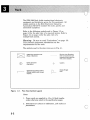
This book has six chapters and four appendixes:
Chapter 1, "Introduction," provides general information
on site preparation and customer responsibility.
Chapter 2, "System Specifications," provides system
specifications, such as primary power and environmental
specifications.
o
Chapter 3, "Rack," explains the requirements for the rack
enclosure, including environmental and power
specifications, and limitations.
Chapter 4, "Unit Specifications," provides
three-dimensional views and specifications for system
units.
Chapter 5, "Cable Requirements," provides the
requirements for ordering system cables.
Chapter 6, "Remote Facility," provides a general
description of Remote Service and system requirements for
Remote Service.
Appendix A, "Specification Summary," provides a
specification and noise-emission level chart for the units
integrated in the system.
Appendix B, "Plugs and Receptacles," provides
illustrations of the required plugs and receptacles.
Appendix C, "Planning Checklist," provides a planning
checklist to prepare for installing the system.
o
Appendix D, "Physical Planning Templates," provides
plan views of the 9309 Rack Enclosure you can use to plan
the floor layout of the system.
III
What You Should Know
The system hardware consists of:
•
•
•
•
•
•
The 9309 Rack Enclosure.
The following IBM 9370 rack-mounted System/370
processors:
9373 Model 20
9375 Models 40 and 60
9377 Model 90.
Integrated input/output (I/O) controllers for:
Disk/Tape
Work stations
Telecommunications
Local area network.
Direct access storage devices (DASD).
Magnetic tape drive units.
System/370 block multiplexer channels.
If You Need More Information
Depending on your system equipment, you may find the
following books helpful.
IV
•
IBM System/360, System/370, 4300 Processors,
Input/Output Equipment Installation Manual- Physical
Planning, GC22~7064
•
IBM Input/Output Equipment Reference Installation
Manual- Physical Planning: System/360, System/370,
and 4300 Processors, GC22-7069
•
IBM General Information Manual Installation
Manual- Physical Planning, GC22-7072
•
IBM Communications Terminals Installation
Manual-Physical Planning, GA27-3006
•
IBM 3270 Information Display Station Installation
Manual-Physical Planning, GA27-2787
•
IBM Multiuse Communications Loop Planning and
Installation Guide, GA27-3341
•
Installation and Assembly of Coaxial Cable and
Accessories for Attachment to IBM Products, GA27-2805
c
o
1. Introduction . . . . . . . . . . . . . . . . . . . . . . . . . . . . . 1-1
Your Responsibilities ................................ 1-3
Planning the Layout ................................ 1-3
Planning Checklist ................................. 1-5
Making the Layout ................................. 1-5
Storage and Shipping Environment ..................... 1-6
Electrical Power ................................... 1-7
Primary Computer Power Service .................... 1-7
8ranch Circuits .................................. 1-8
Grounding ..................................... 1-10
Computer Room Emergency Power-Off Controls ....... 1 -10
Lightning Protection ............................... 1-10
Convenience Outlets ............................... 1-11
Power Plugs and Receptacles ........................ 1 -11
Additional Reference Material ........................ 1 -11
2. System Specifications . . . . . . . . . . . . . . . . . . . . . .
Primary Rack Power ................................
Power Control Compartment (PCC) ..................
Power Phase Imbalance ...........................
Plugs and Receptacles:
.... . . . . . . . . . . . . . . . . . . . . . ..
Cooling ..........................................
System Environmental Specifications ...................
2-1
2-2
2-3
2-6
2-6
2-7
2-7
3. Rack . . . . . . . . . . . . . . . . . . . . . . . . . . . . . . . . . . . 3-1
Plan View (Not to Scale) .......................... 3-3
Raised Floor Cutout ................................ 3-6
Rack Specifications ................................. 3-7
Limitations ....................................... 3-8
Requirements ................................... 3-8
Loading the Rack ............................... 3-11
o
4. Unit Specifications . . . . . . . . . . . . . . . . . . . . . . . . 4-1
IBM 9373, 9375, and 9377 Processors .................. 4-2
9373 Processor .................................. 4-2
9373 Processor Specifications ...................... 4-3
9375 Processor .................................. 4-4
9375 Processor Specifications ...................... 4-5
9377 Processor .................................. 4-6
9377 Processor Specifications ...................... 4- 7
I/O Card Unit ..................................... 4-8
I/O Card Unit Specifications ........................ 4-9
9332-400 DASD ................................. 4-10
9332-400 DASD Specifications .................... 4-11
9335-A01 DASD Controller ......................... 4-12
9335-A01 DASD Controller Specifications ............ 4-13
9335-801 DASD .................................. 4-14
9335-801 DASD ............................... 4-14
9335-801 DASD Specifications .................... 4-15
9347 Tape Unit ................................... 4-16
9347 Tape Unit Specifications ..................... 4-17
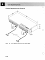
Power Sequence and Control ........................ 4-18
Unit Specifications .............................. 4-19
v
5. Cable Requirements . . . . . . . . . . . . . . . . . . . . . . .
Cable Information ................................. .
Channel Cable Length ............................ .
Coaxial Cable Length ............................ .
Communication Cable Length ...................... .
Cable Schematic ................................ .
System Cabling ................................... .
5-2
5-2
5-2
5-3
5-4
5-6
5-1
6. Remote Facility . . . . . . . . . . . . . . . . . . . . . . . . . . .
General Information .......................... -...... .
Communication Facilities ........................... .
Requirements .................................. .
Remote Facility ................................... .
External Interface Adapter (USA only) ............... .
Customer-Ordering Information For Remote Facility ..... .
6-3
6-4
6-4
6-6
6-6
6-8
6-1
Appendix A. Specification Summary . . . . . . . . . . . .
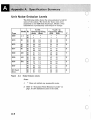
Specification Summary Chart· ....................... .
Acoustics (Noise-Emission Levels) ................... .
Unit Noise- Emission Levels ......................... .
A-1
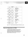
Appendix B. Plugs and Receptacles . . . . . . . . . . . . .
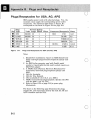
Plugs/Receptacles for USA, AG, APG ................. .
Plugs and Receptacles for EM EA .................... .
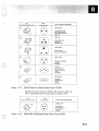
Three- Phase Power Plug ......................... .
50- Hz Power Cord Style ......................... .
B-1
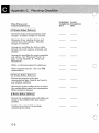
Appendix C. Planning Checklist . . . . . . . . . . . . . . . .
C-1
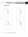
Appendix O.
English Units
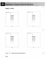
Metric Units
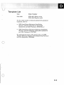
Template List
0-1
0-1
0-2
0-3
Glossary
Index
Physical Planning Templates . . . . . . . .
.....................................
.....................................
.....................................
A-2
A-3
A-4
8-2
8-3
8-6
8-7
(;1
~
X-1
. . . . . . . . . . . . . . . . . . . . . . . . . . . . . . . . . . . . . X-5
o
vi
r?q'rY'Tf;:'t:'t'~'T;,~'~~~<";0'''~:,",,'';'' ~..,,,.'?>,.,_,,,~=_~~_~v_ ~~7·'":':<-~~~~·''''' .«"~o<~" ~~'''::~wl ~".v'.. ~"'»>':~~w":"»:»,~,v,,,,~.:_.,,,~,«,= '«F" N~Y«'~=< "'''>'''' <'
,;;~~~ :.
.'"
'-:'-~'~":C=
'U.* <M"....0WY#~'::~"~~;[;:T::
~:;~~.:'/;:;"
. . »>'--:
77;,~::;·~t:· ':···v<,:,:·~
~ ':;;::' "':~':>':: >.;,,,
:;:1";::
:'~: r;:~
Fig No.
1-1.
2-l.
2-2.
2-3.
3-1.
3-2.
3-3.
3-4.
o
3-5.
3-6.
3-7.
3-8.
4-1.
4-2.
4-3.
4-4.
4-5.
4-6.
4-7.
4-8.
4-9.
5-1.
5-2.
5-3.
5-4.
5-5.
5-6.
6-1.
A-I.
A-2.
A-3.
B-l.
B-2.
B-3.
B-4.
B-5.
B-6.
D-l.
D-2.
Page No.
Power Distribution Systems ..................
Power Control Compartment Versions ..........
Power Control Compartments for EMEA ........
System Environment Specifications ............
Plan View Symbol Legend ....................
9309 Rack Enclosure Models 1 and 2 ............
Plan View for Multiple Racks .................
Weight Distribution/Service Clearance for Multiple
Racks ....................................
Required Service Clearance ..................
Positioning and Dimensions for the Floor Cutout ..
Center-of-Gravity for the Modell ..............
Center-of-Gravity for the Model 2 .............
9373 Processor .............................
9375 Processor .............................
9377 Processor .............................
I/O Card Unit (Features 5010 and 5020) ..........
9332 Model 400 DASD ......................
9335-A01 DASD Controller ..................
9335-B01 DASD ...........................
9347 Tape Unit ...........................
Power Sequence and Control Unit (Feature 6001).
Cable Schematic ...........................
Channel Cabling Chart ......................
Cables to the 9370 Processor ..................
Control Unit-to-Channel Cabling ..............
Cables for Asynchronous Protocol Adapter ......
Cables for Multi-Protocol Adapter ............
Remote Facility Configuration ................
Unit Specification Summary ..................
Noise Emission Levels .......................
Power-Emission Level for Sample Configurations ..
Plugs and Receptacles for USA and AG, APG .....
Plug and Connector/Receptacle for USA, AG, and
A/PG' ....................................
EMEA Plugs for Single-Phase Power (3 kVA) .....
EMEA 200 - 240 Single-Phase Power Plug (5 kVA) .
Three-Phase Power Plug (for 15 Amps) ..........
Power Cord Style (50-Hz Reference) ............
Physical Planning Template (English) ..........
Physical Planning Template (Metric) ...........
1-9
2-4
2-5
2-7
3-2
3-3
3-4
3-5
3-5
3-6
3-9
3-10
4-2
4-4
4-6
4-8
4-10
4-12
4-14
4-16
4-18
5-4
5-6
5-7
5-9
5-10
5-11
6-6
A-2
A-4
A-5
B-2
B-3
B-5
B-5
B-6
B-7
D-l
D-2
o
VII
B
b
0
CD
c:
CJ
~
0
§=
==:
t:J
~
~
ac=:ss
-
:::::
-==:
en
:::=
[J
IJ
~
~
~
Q
----------- --~
C
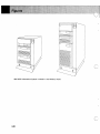
IBM 9370 Information System in Model 1 and Model 2 Racks
c"
viii
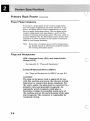
Your Responsibilities ................................ 1-3
Planning the Layout ................................ 1-3
Planning Checklist ................................. 1-5
Making the Layout ................................. 1-5
Storage and Shipping Environment ..................... 1-6
Electrical Power ................................... 1-7
Primary Computer Power Service .................... 1-7
Branch Circuits .................................. 1-8
Grounding ..................................... 1-10
Computer Room Emergency Power-Off Controls ....... 1-10
Lightning Protection ............................... 1 -10
Convenience Outlets ....... ;....................... 1-11
Power Plugs and Receptacles ........................ 1-11
Additional Reference Material ........................ 1-11
o
o
1-1
' ':- >, ,,"-
-<
,.~
"
; .. <:..,,,,,
,>
';' ,
i.~. "
, ;-~,;""
~"
~,:.: <'.).'".':;:.- ~.':< '::~:<>.,.-.
,.,;
The 9370 system includes the 9370 Processors, which are
air-cooled, compatible with System/370, and reside in the
IBM 9309 Rack Enclosure (for clarity, rack will be used in
the rest of this book). There are four versions of the 9370
Processor.
•
•
•
9373 Model 20
9375 Models 40 and 60
9377 Model 90.
These processors use microcode-driven input/output (I/O)
controllers (residing on logic cards) to attach I/O units.
Some of the highlights of the 9370 system include:
•
Rack-mounted I/O units
Direct access storage units
Tape units
•
An integrated DASD/Tape Controller
• A System/370 Block Multiplexer Channel, which
allows you to use System/370 channel-attached devices
1-2
•
A Work Station Subsystem Controller (uses 3270-type
terminals)
•
Four communication subsystems, which allow you to
communicate over synchronous and asynchronous
lines
•
Local Area Network subsystem.
o
Your Responsibilities
Site preparation for the system is your responsibility.
This book can help you prepare for installing and
expanding your system. Although you are responsible for
this activity, you may need help from IBM, consultants,
contractors, or vendors to complete the tasks.
The primary task of the site planner is to identify the
physical space and system layout requirements for the
equipment. Appendix D, "Physical Planning Templates,"
supplies paper cutouts of the rack to help plan the layout.
[Plastic templates in English (GX24-4046) and metric
(GX24-4047) units are available.]
Site preparation includes:
o
•
Adhering to the planning schedules.
•
Preparing the physical location of the units (floor
planning).
o
Obtaining, installing, and maintaining coaxial cables
for work stations or the IBM cabling system.
o
Inspecting the site to insure that each unit will fit
through doorways and passageways.
•
Arranging for installation of any communication
facilities (common carrier, postal telephone and
telegraph, or private) and connecting the system to
these facilities.
•
Performing similar planning functions for IBM
input/output (I/O) devices that you plan to attach to
the processor.
Planning the Layout
Operational requirements determine where you place
system components. Some considerations include:
o
•
Flow of work and personnel within the area
•
Location of planned safety equipment
•
Necessity for maintaining service clearances for all
system units
.
1-3
Planning the Layout
(Continued)
•
Priority of channel-attached devices
•
Space limitations, such as floor-loading capacity,
location of columns, and provisions for growth
•
The length of the cables connecting the units in the
system
•
Visual access required between a control unit and at
least one of its associated I/O devices
•
Work space and aisles.
You may need to prepare and analyze several layouts
before choosing the final layout. If you plan to install the
equipment in two or more stages, prepare a separate
layout for each stage. Consider channel priority
assignments and cable lengths for each stage.
To make a layout, you need an accurate drawing of the
proposed area. For a precise layout, use the paper
templates in Appendix D or order clear plastic templates
(English GA24-4046, metric GA24-4047). The templates
show the required space for weight distribution and
clearances for the operator, service personnel, and test
equipment. Templates also show the radii of swinging
gates and covers, and the location of casters and frame
entry/exit cutouts for cables.
o
Note: You may overlap clearances shown on the
templates if you maintain the larger clearance. The gate
swing of an auxiliary unit must not interfere with the
gate swing of its corresponding control unit.
Place the equipment so that the lengths of the connecting
cables do not exceed the maximum limits; these limits may
vary. Refer to the device specification pages and cable
schematics for the appropriate limits.
o
1-4
Planning Checklist
The planning checklist (Appendix C, "Planning
Checklist") provides a suggested schedule. Your site
preparation may not require all of the suggested steps, or
you may require some additional steps. Be sure you allow
enough time to complete the necessary steps before your
system arrives.
Making the Layout
o
The prepared layout must be accurate and drawn to scale.
If necessary, IBM uses the layout to determine the
appropriate cable lengths [EMEA (IBM Europe/Middle
East/Africa) has fixed length cables.] Be sure to include
the following items, and any other unique considerations,
on the layout:
•
•
Service clearances required for each unit.
Location of:
Power receptacles
Air conditioning equipment and controls
File cabinets, desks, and other office equipment
Room emergency power-off controls
All entran"ces, exits, windows, and columns or
pillars.
•
The number of:
Control units assigned to each channel
The number of input/output units attached to each
control unit.
Special tasks that you must do for a raised-floor
environment include:
o
•
Showing the location of any obstruction that Inay
affect cable routing.
1-5
;,lhf'ritJifdctitin';
~
-:;-., ," "., :,«,." -,'(
<>
"'\ "
~.",
h<' "~:~~L:;_L:~t~L;:~~2'~~~i:: .:~~~<~~ ~:::;~~:t.,,:':~~.::sv>.:?::_ b.~'A lMx~<;,":;~~~~ij::~,~,c'::9 "', , ~
.. ::
Making the Layout
•
(Continued)
Showing the height of the raised-floor above the base
floor.
Note:
The raised-floor height should be between 155
millimeters (6 inches) and 460 millimeters (18
inches). This height should accommodate piping
and power distribution. The minimum raised-floor
height for the 9370 system, with the System/370
channel feature, is 155 millimeters (6 inches).
However, the height should also have a minimum of
an additional 115 millimeters (4.5 inches) to ensure
you can run cables and connectors over and under
obstacles.
When a raised-floor panel is cut for cable entry or
air register, additional panel support may be
required to restore structural integrity. See
Figure 3-6 on page 3-6 for the recommended floor
cutout dimensions and placement.
Tasks that you must do for a non-raised-floor
environment include:
•
•
•
Showing the planned placement of cables for minimum
obstruction.
Showing the amount of additional cable required, if
the cable route is indirectly between units (such as
along walls or suspended).
Deciding if you need cable guards or ramps to ensure
personnel and equipment safety.
c
Always review the final layout to ensure that cable
lengths do not exceed limitations and that all devices
have proper clearances. Notify IBM immediately of any
layout changes that·affect cable lengths.
Storage and Shipping Environment
IBM designs its units to operate in a controlled
temperature and relative humidity range, and (even when
stored or in shipment) they require some environmental
control. If you store the unit outside the specified limits,
permanent damage can result.
o
1-6
Warning: Do not store a unit in a room that has
chemicals that can cause corrosion damage. See
"System Environmental Specifications" on page 2-7,
and individual specifications in Chapter 4.
When removing a unit for shipment or storage, use the
blocks, braces, and preparation procedures found in the
Packaging Bill of Material. This is a protective package
designed uniquely for each unit, and is available from any
IBM Branch Office.
Ship the units through a household goods carrier (padded
van), with appropriate strapping and padding to avoid
transi t damage.
6;..
,,'#@::Wr'1'"
iN
~)5.·t,,*5N
•
·.,.,;. . .31
Electrical Power
o
Primary Computer Power Service
For maximum reliability, the computer power panel
should connect to feeders that do not serve other loads.
Connect electrical noise-producing devices, such as
accounting equipment, card punches, typewriters, and
calculators to panels separate from those feeding the
computer units.
o
1-7
Electrical Power
(Continued)
o
Branch Circuits
The branch circuit panel for the computer should be in a
convenient, well-lighted area of the computer room.
Protect the individual branch circuits on the panel with
circuit breakers properly rated according to the
manufacturer's specifications and applicable codes. Label
each circuit breaker to identify the branch circuit it
controls. The power requirements for I/O equipment are
on the unit specification pages in:
•
IBM Input/Output Equipment Installation
Manual- Physical Planning for System/360,
System/370, and 4300 Processors, GC22-7064.
•
IBM Input/Output Equipment Reference Installation
Manual- Physical Planning for System/360,
System/370, and 4300 Processors, GC22-7069.
The grounding wire of the branch circuit must have
insulation and be equal in size to the neutral and phase
conductors.
c
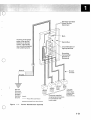
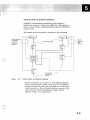
Terminate branch circuits as close as possible to the unit
they supply-within 3 meters (10 feet). Run branch
circuits in either rigid or nonrigid metallic conduit (or in
compliance with local or national standards). The conduit
system should be continuous, uninterrupted, and
connected to the building or transformer ground; see
Figure I-Ion page 1-9.
o
1-8
Remotely Operated
Power Service
.4""'=c-.t--+--+- M a in
Incoming three-phase
power from service
entrance or derived
system, appropriate
over-current protection
and suitable ground.
Ci rcuit Breakers of
Appropriate Size
Grounding
Terminal Bar
(Bonded to
Enclosure)
o
Neutral
Ground
Service
Entrance
Ground or
Suitable
Building
Ground
~Branch
Circuits
0-0---0---
* For loads
208/240V
Legend:
- - - Phase Wires and Neutral
---Insulated Green Wire Ground
o
Figure
1-1.
Customer-supplied
receptacl es/connectors
in accordance with
local codes.
requiring a
neutral. attach
computer/data
processing
equipment only.
Power Distribution Systems
1-9
Electrical Power
(Continued)
Grounding
A machine must be properly grounded. It is recommended
that an insulated green wire ground, the same size as the
phase wire, be installed between the branch circuit panel
and the receptacle. For some small machines such as
terminals, a continuous metallic conduit is adequate for
grounding.
To ensure proper grounding, a licensed electrician should
check the grounding and receptacles for conformance with
the country electrical codes.
For personnel safety, the ground must have sufficiently
low impedance to limit the voltage to ground and to
operate the circuit protective devices if a phase-to-frame
short occurs. For example, the ground path shall not
exceed 1 ohm for 120-volt, 20-ampere branch circuit
devices.
Computer Room Emergency Power-Off Controls
As a safety precaution, provide room emergency power-off
controls for disconnecting the main service wiring that
supplies the computer equipment. Install these controls at
a convenient place for the operator and next to the main
. exit doors of the' room.
Follow national and local electrical codes.
Lightning Protection
You should install lightning protection devices when:
1-10
•
An over!J.ead power service supplies the primary power
•
The utility company installs lightning protectors on
the primary power source
•
The area is subject to electrical storms or
equivalent-type power surges.
o
Convenience Outlets
You are responsible for selecting and installing lightning
protection devices.
Install a suitable number of convenience outlets in the
computer room and the service representative area for use
by building maintenance personnel and service
representatives. Convenience outlets should be on the
lighting or other building circuits, not on the computer
power panel or feeder. Do not use the service convenience
outlets on IBM units for any purpose Qther than normal
servicing.
h,iF
t·!G'@
,tJ
a·ee
i4
Wi
£&9
Power Plugs and Receptacles
All power attachment cable plugs have approval for use
wi th the 9370 system and meet the relevant testing
laboratory or country/test-house standards. All power
cords have the appropriate plugs according to the ship
destination of the system.
o
Note:
'~·!fRi
"?"§if. P!S¥t,;*, B'*,
See Appendix B, "Plugs and Receptacles," for types
of power cord plugs and receptacles.
&* ··P{¥igPie+ i
Additional Reference Material
For more information about domestic standards on site
preparation refer to:
o
o
National Fire Protection Association (NFPA) Standard
No. 75, Protection of Electronic Computer/Data
Processing Equipment (or applicable local or national
equivalent)
IBM General Information Manual, Installation
Manual-Physical Planning, GC22-7072.
Some of the topics in the IBM General Installation
Manual- Physical Planning that you may consider
reviewing for proper site preparation include:
o
o
o
o
•
Environmental Considerations
Acoustics
Electromagnetic Compatibility
Lighting
1-11
Additional Reference Material
•
•
•
(Continued)
Air Conditioning
Temperature and Humidity Design Criteria
Safety and Fire Precautions.
o
o
1-12
'F.~j.MB·;ilI:~~-~~~--~·~-~~~~-------~~=~SP~:~~;xr.;;;:!,~
:;4{;
.. '
~'O~-
Syst&:m;Spec'~:fib~tibns .
Primary Rack Power ................................
Power Control Compartment (PCC) ..................
Power Phase Imbalance ...........................
Plugs and Receptacles:
............. . . . . . . . . . . . . ..
USA, Americas Group (AG), and Asian/Pacific Group
(A/PG) .....................................
Europe/Middle East/Africa (EMEA) ................
Cooling ..........................................
System Environr:nental Specifications ...................
2-2
2-3
2-6
2-6
2-6
2-6
2-7
2-7
o
o
2-1
Xi
i.
.:: . . .
»<'<.;
~.,
,_
The system includes rack-mounted units and peripheral
devices. Refer to the rack and unit specification pages for
power and environmental information.
The system can operate as a stand-alone computer system
or as an information network, connecting to similar
systems and/or host computer complexes. The system can
support many display terminals and printers, including
personal computers.
Primary Rack Power
You must provide primary AC power for the 9309 Rack.
Each rack has a self-contained AC power control
compartment, which distributes AC power to the units in
the rack. Each rack of a multiple-rack system contains
power for the units in its rack.
Each rack has a power cord and plug. A separate outlet
must supply the selected voltage for each rack. The 9309
Rack requires one of the following voltages:
Frequency
Voltage
Nominal Minimum Maximum
50 Hz
200
180
220
220
Single Phase
193
238
230
202
249
240
210
259
60 Hz
Single Phase
50 Hz
Three Phase
120
200
208
220
240
104
180
180
193
208
127 *
220
220
238
254
380
415
333
363
410
448
* Available with the 9309-1
Note:
2-2
rack for the USA.
The tolerance for 50 and 60 Hz is plus or minus 0.5.
o
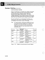
Power Control Compartment (PCC)
The rack has a power control compartment, which serves
as a power source for the system units. This unit
distributes 120-volt (Modell) and 220-volt (both models)
single-phase power to the AC power outlets.
There are five versions of the power control
compartments. Each version is designed for a specific
input power.
The requirements for power and control define the various
versions of the rack. Figure 2-1 on page 2-4 shows the
power and control associated with each type of
compartment. You will receive the default version of the
power control compartment that is listed for your country
under Country in Figure 2-1. You can use the specify
codes to override this default.
o
o
2-3
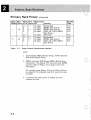
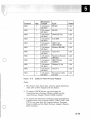
Primary Rack Power
Max. PCC
Rack EIA
Model Units kVA Phase
4.4
2*
1
3
1
19
5
2*
5
1
2
Figure
32
2-1.
2.4
4.4
5
5
1
2
2
1
*
*
(Continued)
Main Line
CB
10 Amps
15 Amps
15 Amps
25 Amps
20
10
15
25
Amps
Amps
Amps
Amps
Country
Switzerland
EMEA (See Note 2)
EMEA (See Note 2)
USA, AG, A/PG, EMEA
(See Notes.)
USA only
Swi tzer land
EMEA (See Note 2)
USA, AG, A/PG, EMEA
(See Notes)
Specify
Code
9114
9112
9113
9111
9115
9114
9113
9111
Power Control Compartment Versions
Notes:
1. AG represents IBM Americas Group; A/PG represents
IBM Asian/Pacific Group.
2. EMEA represents IBM Europe/Middle East/ Africas
Corporation. The default PCC varies for some EMEA
countries. Refer to Figure 2-2 on page 2-5 for more
information.
For example, using Figure 2-2 you see that in France
the default PCC is Specify Code 9111, but 9113 is also
available.
3. * Indicates that input power is 3-phase, but only
2-phases are used.
2-4
'.'/ '"'; ~ ~ *
"~""'"'"fJ
..,,,
"~, ' ",',~""""".~
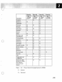
"',-
o
Country
Austria
Belgium
Denmark
Finland
France
Germany
Ireland
Israel
Italy
Kuwait and
Gulf States
N etherlands
Norway
Pakistan
Portugal
Saudia Arabia
South Africa
Spain
Sweden
Switzerland
Turkey
UK
AREAS/South
(AFRICA)
ROECE (IBM
Regional Office
for Europe,
Central and
East)
Figure
2-2.
Specify
Code 9111
1 Phase
5kVA
Specify
Code 9112
1 Phase
3kVA
0
X
X
X
X
X
X
X
X
X
X
0
0
0
0
0
0
0
0
0
0
0
0
Specify
Code 9113
3 Phase
5kVA
X
0
X
0
0
0
0
X
0
X
X
X
X
0
0
X
0
X
0
X
0
X
0
X
Specify
Code 9114
3 Phase
4.4 kVA
X
Power Control Compartments for EMEA
X = Default
o
o
= Optional
2-5
Primary Rack Power
(Continued)
Power Phase Imbalance
If you have a single-phase power control compartment,
you will supply single-phase AC power. However, if you
have a two-phase power control compartment, you will
have to supply three-phase power. The two-phase power
control compartment only uses phases 1 and 2 and the
neutral of incoming three-phase power. This may result in
a power imbalance for the three-phase power system. This
imbalance of power increases as the number of installed
racks in your system increases.
Note:
If you have a two-phase power control compartment,
you should consult an electrician to properly balance
the incoming three-phase power.
Plugs and Receptacles:
USA, Americas Group (AG), and Asian/Pacific
Group (A/PG)
See Appendix B, "Plugs and Receptacles."
Europe/Middle East/Africa (EMEA)
See "Plugs and Receptacles for EMEA" on page B-3.
CAUTION
The plug on the power cord is approved for use
with this machine and meets the relevant testing
laboratory or country/test-house standards. For
the user's safety, the plug must be connected to a
properly wired and grounded receptacle. An
improperly wired receptacle could place a
hazardous voltage on accessible metal parts of
the machine and on the metal housing of the plug
and receptacle. The customer is responsible for
receptacle wiring.
2-6
o
Cooling
Directly forced-air cools the unit. The air intake is
through the front panel and air exhaust is out the bottom
and top of the rack rear door.
For maximum system heat output for the rack and each
unit, see Figure A-Ion page A-2. To determine the total
heat output of your system, identify the units you are
ordering and add the heat outputs specified for those
units.
System Environmental Specifications
Unless otherwise noted on individual specification pages,
the following environmental specifications apply:
o
Environment
Temperature
Operating
10 to 40.6°C
(50 to 105°F)
10 to 51.7°C
(50 to 125°F)
0.6 to 60°C
(33 to 140°F)
-40 to 60°C
(-40 to 140°F)
Non-Operating
Storage
Shipping
Figure
2-3.
Relative
Humidity
8 to 80%
8 to 80%
5 to 80%
5 to 100%)
Maximum
Wet Bulb
26.7°C
(80°F)
26.7°C
(80°F)
29.4°C
(85°F)
29.4°C
(85°F)
System Environment Specifications
o
2-7
o
2-8
Plan View (Not to Scale) .......................... 3-3
Raised Floor Cutout ................................ 3-6
Rack Specifications ................................. 3-7
Limitations ....................................... 3-8
Requirements ................................... 3-8
Appliance Coupler Outlets ....................... 3-8
Center-of-Gravity for A Slide-Mounted Unit .......... 3-8
Center-of-Gravity for the 9309 Model 1 ............. 3-9
Center-of-Gravity for the 9309 Model 2 ............ 3-10
Loading the Rack ............................... 3-11
Power ...................................... 3-11
Stability .............. '. . . . . . . . . . . . . . . . . . . . . .. 3-11
o
o
3-1
The IBM 9309 Rack holds standard-sized electronic
equipment and distributes power for this equipment. All
models conform to the EIA (Electronic Industries
Association) RS-310-C standard for racks, panels, and
associated equipment.
Refer to the following symbols and to Figure 3-2 on
page 3-3 for the plan view of a one-rack system. Refer to
Figure 3-3 on page 3-4 for the plan view of a
multiple-rack system.
Warning: . Be sure to read "Limitations" on page 3-8.
This contains important information on the
requirements for the rack.
The symbols used in the plan views are in Fig. 3-1.
Service Area Boundary
(Service clearances are
measured from machine
with covers closed.)
Cable Entry and Exit Area
(Base of Machine)
Power Cord Exit
(See Note.)
Standard Equipment Outline
(Shows machine with covers
closed.)
Figure
3-1.
+
I~
Casters
Single-Hinged
Door
Plan View Symbol Legend
Notes:
1. Power cords are supplied in 4.3 m (14 feet) lengths,
unless otherwise noted in the specification pages.
2. Dimensions are shown in millimeters, with inches in
parentheses.
3-2
o
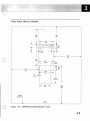
Plan View (Not to Scale)
---------------------------------------------------------------------1--------------------------------------~
T
760
(30)
635
(25)
L-
I
~
I~
610
(24)
T
127
76
(5)
(3)
1220
(48)
c
o
921
(36)
~ +
650
(25 1/2)
I
I~
I
I
26
(1 1/8)
-I
635
(25)
~
I
I
I
I
I
I
I
I
I
I
750
(29 1/2)
~----------------,
rI
I
(3)
...
1220
(48)
I
I
I
+ Itt
482
(19)
-1
*
1650
(65)
Service
Clearance
I
:
J
I
I
I
o
:
FRONT
:----------------- ----------~------------------------------------------------- -----------------------------_.
Figure
3-2.
9309 Rack Enclosure Models 1 and 2
3-3
r---------------------------------------------------------------------------------------------------------------------------r~;-----------------------------
!
f-.. . ------.. -----.. -------------------------.. ------------------.. ------------------------.. -------------.. . -----------.. -------- . ----.. ----.. . ------j
i
Rear
c
1
Right
Left
Side
Side
©
+
@
+
Stabilizer
b
+
+
+
Stabilizer
i
Stabilizer
b'
+
Front
d
t ______________________ J
o
L_______________ J_____________________________________________________________________________________ .. _____ .. _______________________ . . _________________________ 1________________ :
\
Figure
3-3.
Clearances for Service and Weight Distribution
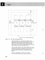
Plan View for Multiple Racks
During installation of a multiple-rack system, when
looking from the front of the racks, identify the racks in a
right-to-Ieft manner beginning with the letter A (see
Figure 3-3). The rack letter has no significance other
than to identify the racks. Identifying the racks will help
you when you run cables from rack to rack.
Allow enough clearance to the right of rack A for another
rack if you have plans to upgrade your 9375 Processor to
a 9377 Processor. The space is also required when
upgrading the 9377 Processor with additional I/O Bus
Units.
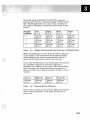
Figure 3-3 and Figure 3-4 identify the required
service/weight distribution clearance required for a
3-4
o
~/'.,
,,
,;'
~ "
" '''~" <
'"-U-~-""-"-'--'~-"~-'.~~'];-"'-""~:-""'~--"'--'.---'''.'---~i.:"::.;s:;::L:J:..!.l.:-kLii..:i..~~~
floor-load rating of 345 kg/m2 (70 lb/ft2). The clearance
assumes each rack has a maximum weight of 478 kg (1,055
lbs). The dimensions for a', b', and c' vary according to
the weight configuration and the floor-load rating of your
facility.
Number
of Racks
1-4
5
6
Figure
o
3-4.
Left
a + a'
1220 mm
(48 in.)
1525 mm
(60 in.)
1525 mm
(60 in.)
Right
b + b'
1220 mm
(48 in.)
1525 mm
(60 in.)
1525 mm
(60 in.)
Rear
c + c'
760mm
(30 in.)
760mm
(30 in.)
915 mm
(36 in.)
Front
d
1650 mm
(65 in.)
1650 mm
(65 in.)
1650 mm
(65 in.)
Weight Distribution/Service Clearance for Multiple Racks
IBM recommends that no more than six racks be adjacent
to one another. This ensures that the maximum one-way
walking distance for a service representative will be 5
meters (16 ft) when he/she works on anyone unit.
If you alter the dimensions, you should obtain the services
of a qualified consultant or structural engineer to
determine floor loading. If the review of the floor-loading
does not require the weight distribution area shown in
Figure 3-3, the service clearances shown in Figure 3-5 are
required.
Left (a)
1220 mm
(48 in.)
Figure
3-5.
Right (b)
1220 mm
(48 in.)
Rear (c)
760 mm
(30 in.)
Front (d)
1650 mm
(65 in.)
Required Service Clearance
These service clearances also meet the office environment
floor-loading requirement of 244 kg/m2 (50 lb/ft2) for a
single rack.
o
3-5
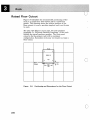
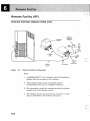
Raised Floor Cutout
Figure 3-6 identifies the recommended positioning of the
rack on a raised floor with 6ID-mm (24-in) raised-floor
panels. This drawing shows the relative position of the
floor cutout; it is not a machine template and is not drawn
to scale.
The plan view (Figure 3-2 on page 3-3) and templates
(Appendix D, "Physical Planning Templates") of the rack
identify the actual machine opening. The floor panel
cutout is for the primary rack with a maximum
configuration. Secondary racks may not require as large a
floor cutout.
Front
+
+
9309-1,2
+
Floor -----Cutout
Figure
3-6
3-6.
Top
+
~.········>\i;i·.•·• · •· •.
I~
45Z
(18)
····.··············l
~I
~
T
127
(5)
Positioning and Dimensions for the Floor Cutout
o
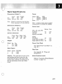
Rack Specifications
Dimensions (Model 1)
Power
Front
650
(25 1/2)
Model
1
2
phase
mm
inches
Note:
Side
921
(36)
Height
1 000
(40)
Height is measured from the floor.
Floor clearance is 75 mm (2.95 in).
50Hz
.093kVA
.093kVA
1,3
60Hz
.093kVA
.093kVA
1
Note: A 3-phase input power control
compartment is available for EMEA.
Dimensions (Model 2)
Power Cord
mm
inches
Front
650
(25 1/2)
Side
921
(36)
Height
1 578
(62)
Service Clearances
mm
inches
o
Front Rear
1 650
760
(65)
(30)
Right Left
1 220 1 220
(48) (48)
Weight
Model
1
2
kg.
107
139
lbs.
(235)
(306)
Meters Feet
USA, AG, and APG
standard
optional
(specify code 9986)
EMEA
two phase
single phase (3 k V A)
single phase (5 k VA)
4.3
1.8
(14)
(6)
4.3
3
4.3
(14)
(10)
(14)
Power Cord Style
See "50-Hz Power Cord Style" on
page B-7.
Heat Output
Plug Type
Model
1
2
Watts
57
57
BTU/HR
(194)
(194)
Airflow: The rack does not have a fan;
each system unit has its own fan. Air
flows from the front to the rear of the
system units, with the air exiting out of
the top and bottom of the rear of the
frame.
See Appendix B, "Plugs and
Receptacles. "
Noise Emission Levels
Refer to "Acoustics (N oise-Emission
Levels)" on page A-3.
o
3-7
Limitations
These requirements reflect some of the conditions under
which the rack and its units were tested for stability and
safety.
It is the responsibility of the customer or unit
manufacturer to assure the rack and its units meet these
requirements. Failure to meet these requirements could
result in an unsafe condition.
Requirements
Appliance Coupler Outlets
The maximum load of the rack outlets for the Power
Control Compartment is:
Countries
Amps
EMEA
10 (IEC3 320)
USA and AG, AjPG 15 (ULjCSA)
o
Center-of-Gravity for A Slide-Mounted Unit
•
The center-of-gravity for an extended unit cannot
exceed 362 mm (14.25 in.) from the face of the rack.
If an extended system unit exceeds this distance, the
configured rack may be unstable.
If you have a rack configuration that exceeds this
center-of-gravity limit, you should test the configuration
for stability to make sure it meets ULI jCSA2
requirements, or the requirements stipulated by the
national test-house for your country.
Underwriters Laboratory
Canadian Standards Association
3
3-8
International Electrotechnical Commission
o
Center-of-Gravity for the 9309 Model 1
The center-of-gravity for the Modell, without any system
units, is as follows.
•
The depth of the center-of-gravity is 495 mm (19.5 in.)
from the front of the rack (measurement does not
include stabilizer).
•
The height from the bottom of the rack (measurement
does not include casters) to. the center-of-gravity is 410
mm. (16.1 in.)
•
The distance from the right edge of the rack to the
center-of-gravity is 292 mm (11.5 in.).
~
!'-'-'-'-'-'-'-'-'-'-'-'i
i
i
1
: +center
of __
1
o
+1
-+__
:
1
~~~
G,.,;ty
495mm
- ~- .- .-.- .-.- .- -~-!
t-!
-i
410t
]<)
Stabilizer
CD
Top View
(Depth)
Figure
3-7.
:r
m
n.)
(J)
~92n:'m~
(11.5 In.}
Front View
Center-of-Gravity for the Model 1
o
3-9
Limitations
(Continued)
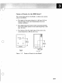
Center-of-Gravity for the 9309 Model 2
The center-of-gravity for the Model 2, without any system
units, is as follows.
•
The depth of the center-of-gravity is 495 mm (19.5 in.)
from the front of the rack (measurement does not
include stabilizer).
•
The height from the bottom of the rack (measurement
does not include casters) to the center-of-gravity is 657
mm. (25.8 in.)
•
The displacement from the right edge of the rack to
the center-of-g:avity is 292 mm (11.5 in.).
it
j-'-'-'-'-'-'-'-'-'-'"]
I
~
1
I
+
1
I
•
+
i
i
Center
of --+--+----,r-
Gravity;
I
.II'-
495mm
(19.5 in.)
4- ~
1+
!
657 mm
(25.6 i n.)
I
!._._._._._._._._._._j
Stabilizer
CD
Top View
(Depth)
Figure
3-8.
o
CD
J
~292 ~m~
(11.5 In.)
Front View
Center-of-Gravity for the Model 2
o
3-10
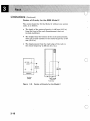
loading the Rack
Warning: Always install the system units in a
bottom-to-top sequence. If you do not install the
system units in this sequence, the rack may become
top heavy - depending on the types and location of the
installed system units.
Power
Besides the single-phase power control compartment, a
three-phase power control compartment is available for
EMEA (Europe/Middle East/Africa) countries.
The maximum input current to the rack with all installed
units must not exceed its power rating (amps, kVA,
frequency, voltage).
o
Stability
The rack stabilizer requires a minimum force of 25 newton
meters (18.5 pound-foree-foot) on each screw. The
limitations described under the following headings must
be followed at all times:
o
Support Rails
Some system units mount in the rack by residing on
support rails. Rail-mounted system units do not slide
out.
Type
Left
Right
Length
725 mm (28.5 in.)
725 mm (28.5 in.)
Part No.
375816
375714
Warning: Each pair of rails is designed to hold a
maximum of 68 kg (150 lbs). All system units
mounted on the rails must be UL listed/recognized
or certified by the eSA (or by the national test
house for your country).
o
3-11
Limitations
•
(Continued)
Support Slides
Some system units mount in the rack by residing on
slides. You can extend slide-mounted units.
Warning: System units mounted on slides must:
Be UL listed/recognized or certified by the eSA
Include an attached label that warns the user
that the rack may tip if more than one
slide-mounted unit is extended in the service
position at the same time. This label must be
visible to the user when the unit is pulled
forward.
Meet weight restrictions:
The maximum weight for a unit on a pair of
slides is 60 kg (132 lbs).
The maximum weight for all units mounted
on slides is 275 kg (606 lbs).
•
o
Weight Restrictions
The maximum weight of the rack with installed I/O
units is 478 kg (1055 lbs).
The maximum weight for all units in the rack is:
Modell
Model 2
190 kg (418 lbs)
320 kg (704 Ibs).
For information on weight distribution for the rack,
refer back to Figure 3-3 on page 3-4.
•
Weight Distribution for System Units
The weight distribution for installed system units
cannot exceed 10 kg (22 Ibs) per EIA unit.
o
3-12
IBM 9373,9375, and 9377 Processors .................. 4-2
9373 Processor .................................. 4-2
9373 Processor Specifications ...................... 4-3
9375 Processor .................................. 4-4
9375 Processor Specifications ...................... 4-5
9377 Processor .................................. 4-6
9377 Processor Specifications ...................... 4-7
I/O Card Unit .............. . . . . . . . . . . . . . . . . . . . . . .. 4-8
I/O Card Unit Specifications ........................ 4-9
9332-400 DASD ................................. 4-10
9332-400 DASD Specifications ..................... 4-11
9335-A01 DASD Controller ......................... 4-12
9335-A01 DASD Controller Specifications ............ 4-13
9335-B01 DASD .................................. 4-14
9335-B01 DASD ............................... 4-14
9335- B01 DASD Specifications .................... 4-15
9347 Tape Unit ................................... 4-16
9347 Tape Unit Specifications ..................... 4-17
Power Sequence and Control ........................ 4-18
Unit Specifications .............................. 4-19
o
o
4-1
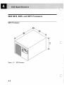
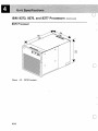
IBM 9373, 9375, and 9377 Processors
9373 Processor
356
(14)
Figure
4-2
4-1.
9373 Processor
c
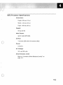
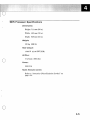
9373 Processor Specifications
Dimensions:
Height: 356 mm (14 in.)
Width: 483 mm (19 in.)
Depth: 660 mm (26 in.)
Weight:
60 kg (132 lb)
Heat Output:
588 W (2,000 BTU/HR)
Airflow:
o
7.9 m 3 /min [280 cubic foot meters (cfm)]
Power:
0.70 kVA
AC Voltage:
120 and 220 volts
Noise-Emission Levels
Refer to "Acoustics (Noise-Emission Levels)" on
page A-3.
o
4-3
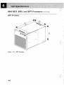
IBM 9373, 9375, and 9377 Processors
(Continued)
9375 Processor
711
(28)
o
Figure
4-2.
9375 Processor
o
4-4
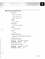
9375 Processor Specifications
Dimensions:
Height: 711 mm (28 in.)
Width: 483 mm (19 in.)
Depth: 828 mm (33 in.)
Weight:
132 kg (290 lb)
Heat Output:
1 800 W (6,145 BTU/HR)
Airflow:
o
17 m3/min (600 cfm)
Power:
2.00 kVA
Noise-Emission Levels
Refer to "Acoustics (Noise-Emission Levels)" on
page A-3.
o
4-5
IBM 9373, 9375, and 9377 Processors
(Continued)
9377 Processor
711
(28)
o
Figure
4-6
4-3.
9377 Processor
9377 Processor Specifications
Dimensions:
Height: 711 mm (28 in.)
Width: 483 mm (19 in.)
Depth: 828 mm (33 in.)
Weight:
122 kg (268 lb)
Heat Output:
1 200 W (4,100 BTU/HR)
Airflow:
o
11 m 3/min (380 cfm)
Power:
1.70 kVA
Noise-Emission Levels
Refer to "Acoustics (Noise-Emission Levels)" on
page A-3.
Operating Environment:
Temperature
ReI Humidity
Max Wet Bulb
15.6 to 32.2°C
20 to 80%
22.8°C
(60 to 90°F)
(73°F)
Nonoperating Environment:
Temperature
ReI Humidity
Max Wet Bulb
10 to 43.3°C (50 to 110°F)
8 to 80%
26.7°C
(80°F)
o
4-7
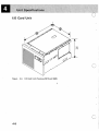
I/O Card Unit
356
(14)
o
Figure
4-4.
I/O Card Unit (Features 5010 and 5020)
c
4-8
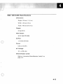
I/O Card Unit Specifications
Dimensions:
Height: 356 mm (14 in.)
Width: 483 mm (19 in.)
Depth: 654 mm (26 in.)
Weight:
55 kg (120 lb)
Heat Output:
211 W (720 BTU /HR)
Airflow:
o
0.43 m 3/min (15.0 cfm)
Power:
0.90 kVA
Noise-Emission Levels
Refer to "Acoustics (Noise-Emission Levels)" on
page A-3.
Operating Environment:
Same as the 9377 processor.
Nonoperating Environment:
Same as the 9377 processor.
Note: Feature 5010 is a one-bus I/O Card Unit and
Feature 5020 is a two-bus I/O Card Unit. These features
are only available with the 9377 processor. One I/O Card
Unit (Feature 5020) is standard with a 9377 processor.
o
4-9
9332-400 DASD
Figure
4-5.
9332 Model 400 DASD
o
c
4-10
9332-400 DASD Specifications
Dimensions:
Height: 133 mm ( 5 1/4 in.)
Width: 483 mm (19 in.)
Depth: 592 mm (23 1/3 in.)
Weight:
30 kg (65 Ib)
Heat Output:
262 W (895 BTU/HR)
Airflow:
o
1.4 m 3/min (50 cfm)
Power:
0.50 to 0.70 kVA
AC Voltage:
115 or 230 volts
Noise-Emission Levels
Refer to "Acoustics (Noise-Emission Levels)" on
page A-3.
o
4-11
9335-A01 DASD Controller
o
Figure
4-6.
9335-A01 DASD Controller
o
4-12
«
O~~~"'W'«' ~
OW
'~'~ mp'ww >'0~~~.~:~: :'f~·!:;;1'~~'?:~·~''''~~~:'7 7> /'.::"~ T~>TTT~:'~~~<~:~~':~:~~;;C:~~~' ~~77::::~~: ;~
"
.'c : ","
, .
<t,
:,,:',':;{; ;:}:':~:;'~,:~;Jr; :~;;::;~,;::;;: ::\:;,:; .
:,,', {:' " ~ ;'\~: ,,>' ~ :~ :::: :" <'<~: ~
,~ "~
.,."
": <"
',~ ::: \',
.'=
;'~,~?~,
,: ',.,.
;.;, :,
,.~;,
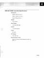
9335-A01 DASD Controller Specifications
Dimensions:
Height: 135 mm (5 1/4 in.)
Width: 445 mm (17 1/2 in.)
Depth: 560 mm (22 in.)
Weight:
17kg(38Ib}
Heat Output:
175 W (597 BTU/HR)
Airflow:
o
1.8 m3/min (64 cfm)
Power:
0.24 kVA
AC Voltage:
180 to 259 volts
Noise-Emission Levels
Refer to "Acoustics (Noise-Emission Levels)" on
page A-3.
o
4-13
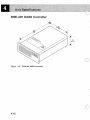
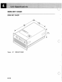
9335-801 DASD
9335-801 DASD
267
(101/2)
Figure
4-7.
9335-801 DASD
o
4-14
V«'~"""''W'''':<'«_«=»>'':~l:l*''«o/w<:"<:""«:»>,:".."..,...."".,=,w~,:,';'':,,,,:,,w'''''''''''_'?'~~,
," 7~~~~-,
<' ~'~,~<~<
<'~~~'--~.
".::
. ,::.
~. ~
":::'~;-::::-:::·-::::TEE~Em:;~~\
<
;:i
'f, "'"
+::f'
< ,\
:i,' :~:\, .;;. :":, .~
'".,';
~
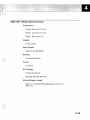
9335-801 DASD Specifications
Dimensions:
Height: 267 mm (10 1/2 in.)
Width: 445 mm (17 1/2 in.)
Depth: 685 mm (27 in.)
Weight: .
60 kg (132 lb)
Heat Output:
430 W (1,467 BTU /HR)
Airflow:
o
2.4 m 3/min (85 cfm)
Power:
0.72 kVA
AC Voltage:
Switch setting for:
208, 220, 230, and 240 volts
Noise-Emission Levels
Refer to "Acoustics (Noise-Emission Levels)" on
page A-3.
o
4-15
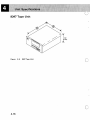
9347 Tape Unit
Figure
4-8.
9347 Tape Unit
o
o
4-16
~:~';~;.;;7:~~;-",·"'·~";~~~r-w"'~:
')
'/ <
, ...
"
~ 0
",.'
'-,.y
.',
;.)~:":1~~;~
'v ,:·::~;>::~.r:;~ ";'><
F'.~.~<~
;'.~ ~ ~ .'".,.,
"
,;,"'.
,
.
:";' ,
>
".~,
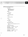
9347 Tape Unit Specifications
Dimensions:
Height: 222 mm (8 3/4 in.)
Width: 483 mm (19 in.)
Depth: 559 mm (22 in.)
Weight:
37 kg (82 Ib)
Heat Output:
270 W (925 BTU/HR)
Airflow:
1.4 m 3/min (50 cfm)
o
Power:
0.30 kVA
AC Voltage:
115 or 230 volts
Noise-Emission Levels
Refer to "Acoustics (Noise-Emission Levels)" on
page A-3.
Operating Environment:
Temperature
ReI Humidity
Max Wet Bulb
15.6 to 32.2°C
20 to 80%
22.8°C
(60 to 90°F)
(73°F)
Nonoperating Environment:
Temperature
ReI Humidity
Max Wet Bulb
10 to 43.3°C (50 to 110°F)
8 to 80%
26.7°C
(80°F)
o
4-17
Power Sequence and Control
rj!!,I
80
(3)
c
Figure
4-9.
Power Sequence and Control Unit (Feature 6001)
o
4-18
Unit Specifications
Dimensions:
Height: 80 mm ( 3 in.)
Width: 434 mm (17 in.)
Depth: 217 mm (8 1/2 in.)
Weight:
7 kg (15 lb)
Note: The power sequence and control unit (Feature 6001)
is only available on the 9375 and 9377 Processors. For
more information see Chapter 5, "Cable Requirements,"
and Planning For Your System, GA24-4030.
o
o
4-19
o
o
4-20
Cable Information .................................. 5-2
Channel Cable Length ............................. 5-2
Coaxial Cable Length ............................. 5-2
Communication Cable Length ....................... 5-3
Cable Schematic ................................. 5-4
System Cabling .................................... 5-6
Channel Cables ................................ 5-6
Cables To The 9370 Processors ................... 5-7
Control Unit-to-Channel Cabling .................. 5-9
Communication Cables ......................... 5-10
Work Station Cables ........................... 5-12
o
o
5-1
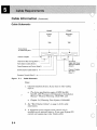
Cable Information
When you draw the floor plan of the data processing area,
know the location of the external devices so that you can
determine the maximum cable lengths. For World Trade,
the devices have to be placed according to the standard
cable length available.
Channel Cable Length
Determine the cable length by measuring the cable path
from the cable entry/exit cutout of the device/control unit
to the entry/exit of the rack. When you measure this
length, remember:
•
Include the distance from the edge of the unit to the
center of the cable entry/exit hole in the unit.
•
Never include any under the cover cable measurements;
IBM allows for these when building external channel
cables.
•
In a raised-floor environment, add twice the height of
the. raised floor to the cable length between the
attached units.
o
Coaxial Cable Length
Measure work station cables from the connector on the
work station to the connector on the system; be sure to
consider the intended cable route, including diagonal and
vertical cable runs. Also, remember:
•
The cable connectors on the system depend on the
location of the feature card.
•
The rack has a cable clamp at the bottom of the frame
near the cable entry. Route cables through this clamp,
then to the connectors.
•
Add 0.6 meter (2 ft) to the length of each work station
cable to allow for slack in the cable.
o
5-2
Communication Cable Length
To find the length of the communication attachment,
measure from the cable entry/exit hole of the system to
one of the following:
•
The external modem or auto-call unit
•
The digital-network channel service unit
•
The teleprocessing line connector
•
The protective device, where such a device
communicates with a switched teleprocessing line.
o
o
5-3
Cable Information
(Continued)
Cable Schematic
FRONT
FRONT
Primary
Rack
Secondary
Rack
TOP
TOP
Frame Cutout
for Cable Entry/Exit
Channel Tailgate
Channel I/O Bus and Tag (Note 1)
Work Station Cables (Note 2)
Power Sequence and Control (Note 3)
Communication Cables (Note 4)
Multi-Rack
Signal and Power
Sequence Cables
(Note 6)
c
Channel Tailgate
9377 Only
(Note 7)
Processor Console (Note 5)
Figure
5-1.
Cable Schematic
Notes:
1. Channel-attached devices. If you have to order cables,
refer to:
•
The device specification pages of IBM Sys/360,
Sys/370, 4300 Processors I/O Equipment Installation
Manual- Physical Planning, GC22-7064, and
•
Chapter 5 of Planning Your System, GA24-4032.
2. See "Work Station Cables" on page 5-12 for cable
information.
3. A 16-position power sequence and control unit is
available as an optional feature. If you want System/370
control unit sequencing, order Feature 6001.
5-4
c
4. See "Communication Cables" on page 5-10 for required
cables.
5. A signal cable for the processor console is shipped with
the processor [fixed length: 7.6 meter (25 ft)]. Two
additional signal cables for the processor console (and
the RSF modem) are shipped with the processor [fixed
length: 7.6 meter (25 ft)]. These cables are for the remote
support and auto start operations. Auto start operations
only become active when the rack has the security key
lock installed.
6. This cable controls power on/off and emergency
power-off from rack-to-rack in a multiple-rack system. A
3-meter (10-ft.) power sequence cable is shipped with
each secondary rack. An optional 6-meter (20-ft.) cable is
also available.
Note:
o
The Hands On Network Environment (HONE)
configurator will prompt you for the required
specify codes to order the appropriate cables for
all connections within and between units
mounted in the rack(s).
7. The 9377 Processor requires an I/O Card Unit (Feature
5020) in a primary and/or secondary rack to attach
System/370 channel devices.
o
5-5
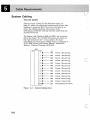
System Cabling
Channel Cables
Figure 5-2 and "Cables To The; 9370 Processors" on
page 5-7 relate the cable group numbers and feature code
numbers to connector IDs. If you know the features on
order, the cabling schematic shows most of the
information needed for ordering external cables from the
channel I/O device.
The feature code (Features 6003 and 6001) and connector
IDs of the cables "To" the 9370 Processors are shown on
the right (connector ID = even number). For more
information on the channel cabling charts, see Chapter 6
of the IBM General Information Manual, Installation
Manual- Physical Planning, GC22-7072.
9370
ID
10
2
.........
4
.....
5-6
5-2.
Channel
6003
Channel 1 (Bus and Tag)
o (Bus and Tag)
6003
Channel 2 (Bus and Tag)
8
....
.......
.......
6003
Channel 3 (Bus and Tag)
10
.....
....
6003
Channel 4 (Bus and Tag)
12
.........
6003
Channel 5 (Bus and Tag)
14
.......
6003
Channel 6 (Bus and Tag)
16
.....
....
6003
Channel 7 (Bus and Tag)
6
Figure
FC
6003
.....
18
....
6003
Channel 8 (Bus and Tag)
20
""""I"'-
6003
Channel 9 (Bus and Tag)
22
.........
6003
Channel 10 (Bus and Tag)
24
.........
6003
Channel 11 (Bus and Tag)
26-56
.........
6001
Power Sequence and Control
Channel Cabling Chart
0
Cables To The 9370 Processors
The following cables are ordered with "Group Numbers"
identified on the specification pages of the System/370
channel-attached device.
Conn.
o
Feature
6003
6003
6003
6003
6003
6003
6003
6003
6003
6003
6003
6003
6001
Figure
5-3.
ID
2
4
6
8
10
12
14
16
18
20
22
24
26-56
Comments
Channel 0, Bus & Tag
Channell, Bus & Tag
Channel 2, Bus & Tag
Channel 3, Bus & Tag
Channel 4, Bus &'Tag
Channel 5, Bus & Tag
Channel 6, Bus & Tag
Channel 7, Bus & Tag
Channel 8, Bus & Tag
Channel 9, Bus & Tag
Channel 10, Bus & Tag
Channel 11, Bus & Tag
Power Sequence and
Control
Notes
1,2,3,4
1,2,3,4,5
1,2,4,5
1,2,5
1,2,5
1,2,5
1,2,5
1,2,5
1,2,5
1,2,5
1,2,5
1,2,5
6,7
Cables to the 9370 Processor
Notes:
1. The maximum cumulative cable length available to
attach up to eight control units is 122 meters (400 ft),
unless modified by the general control unit-to-channel
cabling schematic.
2. The block multiplexer channel (Feature 6003) contains a
single card and a cable set. The cable set connects to the
channel card on one end and to the channel box
(System/370) connector on the other end.
3. Channel 0 is optional on the 9373 Processor. The
channel on the 9373 Processor is restricted to two
controllers: a tape controller and/or a printer.
o
4. Channels 0 and 1 are optional on the 9375 Processor.
Channel cards are installed only in two of the five slots
of the top card enclosure in the processor unit.
5-7
System Cabling
(Continued)
5. Channels 0 through 11 are optional on the 9377
Processor. Channel cards can be installed only in the
two-bus 110 Card Unit (Feature 5020). The 110 Card
Unit can be installed in a secondary rack. Your physical
layout will depend on the number of system racks you
have.
6. Power sequence and control is an optional feature with
the Systeml370 channel feature. It enables 110 control
units to power onloff sequentially when the system
powers onloff. Power sequence and control is available
for a maximum of sixteen control units. Order Feature
6001 for the power sequence and control positions. The
connector IDs for the sixteen positions are even
numbers; 26, 28, 30, 32, 34, 36, 38, 40, 42, 44, 46, 48, 50,
52, 54, and 56.
7. For more information on power sequencing, refer to
Systeml360, Systeml370 Power Control Interface OEMI,
GA22-6906.
o
o
5-8
Control Unit-to-Channel Cabling
Generally, the maximum cumulative cable length to
attach to a channel is 122 meters (400 feet). Exceptions to
this are noted on the cabling schematics for the individual
control units.
All control units are serially connected to the channels.
Power Sequence
and Control"
gof~rr;la~~it
............... .. _- .......
.'
------(,'
Position)
J
I Channel 2 F-
-?l Channel 1 J
I
~
-
~
"
~ I/O Interface Cables
~~
~
Control
Unit
No.1
.'
-
1
~,
5-4.
-------
Control
Unit
No.3
Control Unit
No.2 (with
Two-Channel
Capability)
Control
Unit
NO.3
......-..... _-
Power
Sequence
and
Control"
t
~
Figure
..r-----
"-
Control
Unit
No.1
.. .... ---- -....... _- .....
'....
-'- .... _-- -_ ... -_ . - .'
'---
o
,*,-
)
To Additional
Control Units
(Max 8)
~
Control Unit-to-Channel Cabling
* Power sequencing is an option on most IBM equipment.
Power sequence and control cables need not be ordered
unless you want to power the equipment on or off from a
single location, or the individual machine requires it for
other reasons. See the specification pages for the
specific control unit requirement.
o
5-9
System Cabling
(Continued)
Communication Cables
Figure 5-5 and Figure 5-6 identify the interface and cable
length of the Communications Processor (Feature 6030)
for the Asynchronous Adapter (Feature 6032) and
Multi-Protocol Adapter (Feature 6031). Two other
adapters supported by the Communications Processor are
the IBM Token-Ring Adapter (Feature 6034) and the IEEE
802.3 Local Area Network (LAN) Adapter (Feature 6035).
For more information on communication features, see
Planning For Your System, GA24-4032, and Introducing
The IBM 9370 Information System, GA24-4030.
Note:
All communication cables [except IEEE 802.3 Local
Area Network (Feature 6035)} will be shipped with
the feature. For more information on local area
network and connectors, see the communications
cable guide (ask your sales representative for the
availability date).
Feature
6032
Qty.
1
Maximum
Length
6.0 meters
(20 feet)
15.2 meters
(50 feet)
6.0 meters
(20 feet)
6032
1
6032
1
6032
1
6.0 meters
(20 feet)
6032
1
6.0 meters
(20 feet)
Figure
5-5.
Type
Asynchronous
RS-232
Asynchronous
RS-422
Asynchronous
Modem
(V.24/RS-232)
Asynchronous
System-to-System
(RS-232)
Extension Cable
(25 pin)
Notes
1,2,4
o
1,2,4
1,2,4
1,2,4
1,2,5
Cables for Asynchronous Protocol Adapter
o
5-10
Feature
6031
o
Qty.
1
6031
1
6031
1
6031
1
6031
1
6031
1
6031
1
6031
1
6031
1
6031
1
6031
1
6031
1
Figure
5-6.
Maximum
Length
6.0 meters
(20 feet)
15.2 meters
(50 feet)
6.0 meters
(20 feet)
6.0 meters
(20 feet)
6.0 meters
(20 feet)
6.0 meters
(20 feet)
6.0 meters
(20 feet)
6.0 meters
(20 feet)
6.0 meters
(20 feet)
6.0 meters
(20 feet)
6.0 meters
(20 feet)
6.0 meters
(20 feet)
Type
RS-232
Notes
1,3,4
RS-422
1,3,4
Network X.21
1,3,4
X.21 BIS
1,3,4
DDS V.35
(DSU/MOD)
Modem (RS-232)
1,3,4
1,3,4
Auto-call
1,3,4
System-to-System
(RS-422)
IBM Wiring
422/ECL
Modem (V.24)
1,3,4
1,3,4
422 LC-l
1,3,4
Extension Cable
(25 pin)
1,3,4
1,3,4
Cables for Multi-Protocol Adapter
Notes:
1. The feature code, device type, and line speed determines
what cable will be shipped with the feature.
2. To support ASCII devices, you must have the
Comrnunications Processor (Feature 6030) and the
Asynchronous Adapter (Feature 6032) installed.
o
3. To support the standard synchronous and asynchronous
communication line protocols (SDLC, HDLC, BSC, and
TTC2), you must have the Communications Processor
(Feature 6030) and the Multi-Protocol Adapter (Feature
6031) installed.
5-11
System Cabling
(Continued)
4. Each Multi-Protocol Adapter supports two lines and
each Asynchronous Adapter supports four lines.
5. The maximum configuration for the Communications
Processor is:
•
Any combination, maximum of three, of the
Multi-Protocol Adapter and Asynchronous Adapter,
or
•
Four Asynchronous Adapters using the ASCII
Subsystem (16 lines), or
•
One IEEE 802.3 Local Area Network (LAN), or
•
One IBM Token-Ring Adapter.
Work Station Cables
I
To attach the selected devices to the processor, you must
have. the Work Station Controller (Feature 6020).
A multiplexer, such as the 3299, can attach ports 1, 4, 5,
and 6 of the work station adapter. This allows you to
attach up to 32 devices. For more information, refer to
Chapter 3 in Planning For Your System, GA24-4032.
o
You are responsible for ordering, installing, maintaining
and testing all cabling between work stations and the
system. Work station cabling is available from IBM,
either assembled or unassembled. Test and install your
work station cables before the scheduled arrival of the
system.
For cable specifications and ordering information, refer to
the specification pages of the appropriate Installation
Manual- Physical Planning for the peripheral device.
For cable installation information, refer to Installation
and Assembly of Coaxial Cable and Accessories for
Attachment to IBM Products, GA27-2805.
When planning for the required cables, identify each cable
end (work station and processor connector number) with
the cable lengths and addresses. Document this
information on your floor plan and Form D in the
Planning Forms, GA24-4093.
5-12
o
I
.~.
x ~
. :/~-....f~~Ii:t~~c:J:rF~§bH:Y>·
General Information .................................
Communication Facilities ............................
Requiremerits ...................................
Remote Facility ....................................
External Interface Adapter (USA only) ................
Customer-Ordering Information For Remote Facility ......
6-3
6-4
6-4
6-6
6-6
6-8
o
o
6-1
The Remote Facility is a standard feature on all 9370
Processors. In the event the system malfunctions, the
Remote Facility allows fast maintenance response. It also
allows you to control the processor at a remote location.
The Remote Facility provides the following functions:
"
•
Remote Service transfers system error data to the
IBM support system. This also allows service
representatives to control and analyze the system from
a remote location.
•
The Remote Operation allows you to control multiple
systems from a central site.
The connection to the 9370 is through the processor
console with a synchronous communication data link. In
the USA and Canada, IBM will provide a 2400
bit-per-second (bps) modem with auto-answer capability.
World trade customers have to provide a modem according
to country regulations and specifications identified in this
chapter.
o
o
6-2
General Information
To establish a switched network data connection in
manual operation, you need a telephone:
•
To call or answer a call and
o
To switch the circuit to the modem to transfer the
data.
The following applies for the USA and Canada:
o
•
You must provide a telephone that uses a modular
jack. You should also have the switched network line
terminated at your site.
•
The Federal Communications Commission (FCC), Part
68, Rules and Regulations (July 1979) also affect
customer premises equipment (CPE), such as
telephones and modems. Part 68 requires FCC
registration of all CPE attached to the public switched
telephone network. (It also requires protective circuits
to protect the switched telephone network.)
o
Protective circuits can be provided in two forms. Some
configurations use a data protective coupler, which
goes between an unprotected modem and the switched
telephone network. More recently designed modems,
such as the IBM 5842, include the protective circuit
within the modem so that it does not require an
external coupler ..
World Trade countries must follow equivalent regulations.
o
6-3
Communication Facilities
In the USA and Canada, IBM will provide a 2400 bps,
manual dial, auto-answer modem that includes protective
coupler circuits as part of the 9370 processor console.
You will need to:
•
Obtain a dedicated switched network line that
terminates at an RJll data jack (four-position modular
jack). This should terminate within 4.5-meters (15-feet)
of the processor console and modem.
Note:
IBM provides a 4.5 meter (15 foot) cable for use
between the modem and the switched line data
jack (see Figure 6-1 on page 6-6).
•
Provide a- normal telephone with a modular plug that
is compatible with the type of phone line service (pulse
or tone dialing).
•
Register the modem and telephone, after installation,
with the local phone company by using the FCC
registration number and ringer equivalency number
(REN) provided on the equipment.
In World Trade Countries, IBM will supply a compatible
modem, if local communications regulations do not
restrict the IBM support structure. Each country with
restrictions will be handled on an individual basis.
o
Requirements
In the USA and Canada each telephone, modem, and
protective coupler used on the public switched telephone
network must be registered with the FCC. When you order
communication facilities, you must specify, by Universal
Service Order Code (USOC) code, the jacks required to
terminate the line. You must also provide the telephone
company with specific registration information for each
device to be directly attached to the the switched
telephone network. The manufacturer or supplier of the
device will supply this information.
The information the FCC requires is:
•
•
•
6-4
Device name and model number
FCC registration number
Ringer equivalence number (REN).
o
<
'",'.'
,'.""
";'.'
"
",."".,wn<N"'WW '~"'_'W"~W"'WWW'_<"_W_WW"_';W~'':''_M-''~_':.......;..._" _ _ _ ~~W_~
A fixed-length cable is shipped with the processor (see
Figure 6-1 on page 6-6). For convenience, install the
remote facility telephone handset next to the processor
console.
Outside the United States and Canada, you need the
following to connect the Remote Facility:
•
Switched network termination for line plate interface.
o
o
6-5
Remote Facility (R.F)
External Interface Adapter (USA only)
7.6 Meters
(25 Ft)
Figure
6-1.
PIN 62X3422
1.8 Meters
(6 Ft)
Power Cord
o
Remote Facility Configuration
Notes:
1. A RS232C/CCITT V.24, Y-shaped cable (PN 62x3422) is
shipped with the processor to all countries.
2. All customers must provide a switched network
communication line with a compatible telephone.
3. For convenience, install the customer-provided telephone
handset next to the display console.
4. The common carrier must provide the connection or data
jack, as described by the modem instructions.
o
6-6
CDT-Type
Protective
Coupler
Modem
dependent
External Modem Line Connection
Line Type
IBM 5842
Modem or
equivalent (see
Note 2)
Switched
Network Line
for data up to
2400 BPS
OEM
equivalent to
V.22 or V.22 bis
interface and
operation (see
Note 1)
o
Common-Carrier
provided before
Jan. 1, 1983
Common-Carrier
provided USOC
as specified by
OEM instructions
Notes:
1. Additional site planning and preparation may be
required before installing the modem or coupler units.
The modem must provide for synchronous operation
clocking provided by the data communication equipment
(DCE). See the instructions for the device you plan to
use. For FCC regulations, see Original Equipment
Manufacturer (OEM) literature.
2. The 5842 Modem will be shipped to the USA and
Canada. World Trade countries will have to furnish an
equivalent 1200 or 2400 bps, V.22, V.22 bis, or V.23
interface modem with internal clocking.
o
6-7
Remote Facility
(Continued)
Customer-Ordering Informatio,n For Remote Facility
1. Communication Facility Requirements
•
Line Type - Dial-Up Business Line
May be Touch-Tone! or rotary dial
•
Line Speed - 2400 bps
•
Line Termination - IBM 5842 Modem (or
equivalent)
•
FCC Registration information - determined by
customer-supplied modem
2. Modem Requirements
•
IBM 5842 or equivalent V.22 bis for the USA and
Canada.
•
CCITT V.22, CCITT V.22bis, or CCITT V.23 modem
for World Trade countries.
o
3. Telephone Requirement
•
C5 Touch-Tone or C6 rotary dial (must be the same
as line type).
•
Modular jack telephone (or equivalent for World
Trade countries).
Trademark of American Telephone and Telegraph Co.
6-8
o
o
Specification Summary Chart ........................
Acoustics (Noise- Emission Levels) ....................
Unit Noise- Emission Levels ..........................
A-2
A-3
A-4
o
o
A-1
Specification Summary Chart
Type
9309
9373
9375
9377
9332
9335
Model
1
2
20
40, 60
90
400
A01
B01
9347
Figure
A-1.
Unit
Description
1.0 Meter Rack
1.6 Meter Rack
Processor
Processor
Processor
DASD
DASD Controller
DASD
Magnetic Tape
Drive
I/O Card Unit
Max.
kVA
0.093
0.093
0.70
2.00
1.70
0.50
0.24
0.72
0.30
Heat
Output
W BTU/hr
194
57
194
57
588 2,000
1800 6,145
1 200 4,100
262
895
175
597
430
1,467
925
270
0.90
211
720
Weight
kg lb
107 235
138 303
60 132
132 290
122 268
30
65
17
38
60 132
37 82
55
120
EIA.
Units
19
32
8
16
16
3
3
6
5
2
2
2
4
3
3
5
8
8
Notes
1,6,7
Unit Specification Summary
Notes:
1. Specifications include the power control compartment
(PCC).
2. Maximum k V A with maximum storage.
3. Maximum of one 9335 A01 per DASD/ Tape Controller
(Feature 6010). Maximum of four 9335 BOIs per 9335
A01.
4. Maximum of four 9332s and one 9347 per DASD/Tape
Controller (Feature 6010).
5. Maximum of two 9347s per DASD/Tape Controller
(Feature 6010).
6. A total of 5 k VA is the maximum for a Model 2 PCC
and 3 k V A for a Modell PCC. Do not include the
System/370 110 in the k V A total for the rack.
7. Maximum number of EIA (Electronic Industries
Association) units for the Modell is 19 and 32 for the
Model 2.
8. The I/O Card Unit is a feature for the 9377 Processor.
Feature 5010 is a one-bus I/O Card Unit and feature
5020 is a two-bus 110 Card Unit.
o
c
A-2
o
Acoustics (Noise-Emission Levels)
Acoustical data is intended to answer requests for
information and is for consultants and planners requiring
the data to help predict the levels of acoustical noise.
The format in which the data are provided conforms to the
standard used by the computer industry. The
measurement procedures used to acquire the data conform
to American National Standard S12.10-1985 and
International Standard 7779. The following terms are
used to present acoustical data in this manual.
Term
Definition
LwAd
The declared sound power-emission level.
< LpA > m The mean value of the space-averaged sound
pressure emission levels at the one-meter
positions.
T
Prominent discrete tones
o
o
A-3
~\i:IJ.'~(;':::Sp;~Cificati9n •. Sl.lmmary'
'''&'4,;;C,~m",,,~,,,,,~LLL:;::*:,~,",_,,'',,~, ~",";'"i,,';,,:,,;, " ,:,; ".M;," ,,';; ,,': >,,~ *"~'"
Unit Noise-Emission Levels
The following table shows the noise-emission levels for
units of the system. The levels for these units were
measured in the 9309 Rack Enclosure, Model 2. The
information is preliminary and subject to change.
Model Hz
Type
9309
1,2
9373
20
9375
9377
40
60
90
9332
400
9335
A01
9335
B01
9347
I/O Card
Unit
Figure
A-2.
60
50
60
50
60
50
60
50
60
50
60
50
60
50
60
50
60
50
LwAd
Operating Idling
(bels) (bels)
T
*
*
*
*
*
*
N
6.8
6.8
6.6
6.8
6.4
6.6
6.1
6.1
5.8
5.9
7.1
7.2
6.5
6.5
6.7
6.7
50
50
50
51
47
49
46
46
43
44
54
55
51
51
50
50
50
50
50
51
47
49
46
46
43
44
54
55
51
51
50
50
N
*
*
6.8
6.8
6.6
6.8
6.4
6.6
6.1
6.1
5.8
5.9
7.1
7.2
6.5
6.5
6.7
6.7
<LpA>m
Opera ting Idling
(dB)
(dB)
N
N
Y
N
N
o
N
N
Noise Emission Levels
Notes:
1.
* Does not radiate any measurable noise.
2. Refer to "Acoustics (Noise-Emission Levels)" on
page A-3 for definitions used in the table.
o
A-4
Noise levels are not additive. Use the following
logarithmic formula for the emission level of your system
configuration.
The formula for the sound power-emission level of a
sample configuration consisting of a 9375, 9335-A01, and
two 9335-B01s is as follows:
Lsum
=
log [ sum
lOLwAd ]
log [ 1(J3.6 + 1(J5.8 + 107 . 1 + 107. 1 )
log [ 3981071.7 + 630957.3 + 12589254
+ 12589254 }
log [ 29790537 }
7.47 bels
o
The following table lists five sample configurations and the
power-emission levels (LwAd) of each. For example,
configuration IJ includes one 9373, one 9332, and one 9347,
with a power-emission level (LwAd) of 7.0 bels.
iii
Processor
Number of Devices
Model
9332 9335-A 9335-B 9347
9373
1
0
0
1
m
9373
2
0
0
1
B
9375
0
1
2
0
iii
9375
0
1
3
0
Ii
9377
0
1
3
0
Sample
Figure
A-3.
LwAd
7.0
bels
7.1
bels
7.4
bels
7.7
bels
7.7
bels
Power-Emission Level for Sample Configurations
o
A-5
c
o
A-6
Appendix B. PlUgs and
cReceptac,es:1I
Plugs/Receptacles for USA, AG, APG ..................
Plugs and Receptacles for EM EA .....................
Three- Phase Power Plug ..........................
50- Hz Power Cord Style ..........................
8-2
8-3
8-6
8-7
o
o
8-1
IBM supplies power cords with attached plugs. You, the
customer, must supply the corresponding power outlet
receptacles. The reference (Ref) letter in Figure B-1
corresponds to the letter in Figure B-2 on page B-3.
Plug
Ref Type
B 3750
IE] L6-30P
II WIP130
iii 56PA330
0 3720U-l
iii 5-20P
Figure
8-1.
Service Rating
Volts Amps Phase Wires
1
3
220/250 30
1
220/250 30
3
1
250
30
3
250
1
30
3
125
20
1
3
125
20
1
3
Connector/Receptacle
3933
3753
L6-30R
WIBM130
56S0330
3913U-1
3743U-l
5-20R
Notes
1,2,8
3,8
4,8
5,8
1,2,6,8
6,7,8
Plugs and Receptacles for USA and AG, APG
Notes:
1. Raised-floor installations require an R&S (Russell and
Stoll) watertight plug/connector/receptacle (specify code
9080).
2. An R&S in line connector used with flexible metal
conduit or liquid-tight flexible metal conduit requires an
R&S FSA adapter.
3. A NEMA-style (National Electrical Manufacturers'
Association) twist-lock plug/receptacle (specify code
9081).
4. Only for Australia.
5. Only for New Zealand.
6. Only available for the U.S.A. on a 9309-1.
7. NEMA non-twist-lock plug/receptacle. Specify code 9081
with the 9309-1, 120 Vac PCC.
8. Refer to Figure B-2 on page B-3 for power plug
illustrations.
o
The chart on the following page illustrates the plugs,
receptacles, and connectors used by the rack for AG and
A/PG countries and the USA.
c
B-2
.
Plug
Receptacle/
Connector
0 (J
CD
0 0
0 Q
0 Q
®6®
o
ee
@e
Figure
8-2.
Type
Russell and Stoll
Waterproof Plug,
Receptacle/Connector
220/250V 30A
NEMA Twistlock
Plug/Receptacle
220/250V 30A
POL Insulated
Plug/Receptacle
250V/30A
(New Zealand)
Wilco Weatherproof
Plug/Receptacle
250V/30A
(Australia)
Russell and Stoll
Waterproof Plug,
Receptacle/Connector
125V/20A
NEMA
Plug/Receptacle
125V/20A
Plug and Connector/Receptacle for USA, AG, and A/PG
Plugs and Receptacles for EM EA
o
For EMEA countries, IBM supplies the power cord with
an attached plug that corresponds to the power-outlet
receptacle most used in that country. Figure B-3 on
page B-5 shows illustrations of the power plugs for 3 kVA,
single-phase power (specify code 9112). Match the letter
of the illustrations in Figure B-3 with the appropriate
listing of countries on the next page.
8-3
'"."~
B
Plugs and Receptacles for EM EA
(Continued)
Note: * = The power cord for the 3 k V A single-phase
PCC in the United Kingdom does not have a plug.
Country
Plug
ID
Country
Algeria
Andorra
Angola
Austria
Bahrain
Belgium
Benin Republic
Bulgaria
Cameroon
Central Africa Rep.
Chad
Channel Islands
Congo
Cyprus
Czechoslovakia
Egypt
Ethiopia
Finland
France
Germany
Ghana
Guinea
Greece
Hungary
Iceland
Iran
Ireland
Israel
Italy
Ivory Coast
Jordan
Kenya
Kuwait
Lebanon
Libya
Liechtenstein
Luxembourg
Malagasy
Malawi
Maliuras
Malta
A
A
A
A
B
A
A
A
A
A
A
B
A
B
A
A
F
A
A
A
B
A
A
A
A
A
B
D
F
A
B
B
B
A
B
E
A
A
B
A
B
Mauritania
A
A
Mauritius
Monaco
A
Morocco
A
Mozambique
A
Netherlands
A
New Caledonia
A
Niger
A
Norway
A
Oman
B
C
Pakistan
Poland
A
Portugal
A
Qatar
B
Romania
A
Senegal
A
Saudi Arabia
B
Sierra Leone
B
Somalia
B
South Africa
C
Spain
A
Sudan
A
S.A.R. (Southeast Asia Region) A
Tanzania
B
Togo
A
Tunesia
A
Turkey
A
Uganda
B
U.A.E.
B
United Kingdom
*
Upper Volta
A
U.S.S.R.
A
Yemen
B
Yugoslavia
A
Zaire
A
Zambia
B
8-4
Plug
ID
C
C
j~~;;~~::~
,'-"";,,,
'
,
"
'
'
'
;~;,),W;:. __ .,."k..,...;,_","",,~»>.w.~·_ ..
" .j~""",_> ...........""*"",,«>, • ...,.;;-...,~,,,,,,,_.,.,.::;,<Mo;.,,~_
Plug
Three-Dimensional View
[A]
[B]
[C]
[DJ
o
[E J
[F J
Figure
Plug
Pin-Side View
~
e3
~
~
~
~
~
U
t3
~
e
~
Service Rating and Standard
250V 10/16A
International rules
for the approval of
Electrical Equipment
CEE: VII
250V 13A
British Stanards
Institution
BS1363: (U.K.)
250V 10/16A
South African
Bureau of Standards
250V 10/16A
Standards Institution
of Israel
SI-32-1971
250V lOA
Schweizericher
Elektrotechnischer
verein
SEV 24507
250V 10/16A
&:iJ
8-3.
~
Comitato
Elettrotecnico
Italiano
CEI 23-16
EM EA Plugs for Single-Phase Power (3 kVA)
Besides the plugs listed in Figure B-3, there is also a 5
kVA single-phase power plug; refer to Figure B-4.
Plug
Three-Dimensional View
~
•
Plug
Pin-Side View
(oJ
Service Rating and Standard
220/380V 25A
, International
Electrotechnical
Commission
lEG 309
--
o
Figure
8-4.
EMEA 200-240 Single-Phase Power Plug (5 kVA)
8-5
B
Plugs and Receptacles for EM EA
(Continued)
Three-Phase Power Plug
The following three-phase power plug is for the two-phase
power control compartment for EMEA countries.
Note: Power is not balanced using this plug. This plug
only uses phases 1 and 2 of the incoming three-phases.
For more information, refer to "Power Phase Imbalance"
on page 2-6.
Plug
Plug
Three-Dimensional View
Pin-Side View
Service Rating and Standard
220/380V 10/16A
International
Electrotechnical
Commission
lEG 309
Figure
8-5.
o
Three-Phase Power Plug (for 15 Amps)
Legend:
1 = Phase 1
2 = Phase 2
3 = Phase 3
N = Neutral
G = Ground
o
8-6
50-Hz Power Cord Style
The following chart provides power cord specifications
needed to terminate the power cord in accordance with
local practice, if necessary.
CABLE
NominalOD
Phase mm (inches)
1
8.9 (0.350)
9.0 (0.354)
3
CONDUCTORS
Number
NominalOD*
of
Shields Quantity mm (inches)
(0.110)
0
2.8
3
(0.110)
0
2.8
5
* This
Figure
8-6.
Size
mm 2
1.5
1.5
diameter refers to solid, bare wire.
Power Cord Style (50-Hz Reference)
o
o
8-7
-
o
o
8-8
I
This checklist identifies installation tasks and
responsibilities sequentially. If you have to renovate your
site, you will probably need more time and a longer
planning cycle. Use the following schedule and list of
tasks as a guide.
Time Frame and
Task/Consideration
Scheduled Actual
Completion Completion
Date
Date
116 Weeks Before Delivery I
Designate a person in your organization
with the responsibility for all phases of site
preparation.
Review this site planning guide with the
designated person.
o
Plan for the instailation of the device cables
between the devices and the processor. See
Chapter 5, "Cable Requirements."
Determine the schedule with your IBM
representative. Fill in the dates on this
form.
Identify communication needs and the
source for the communication lines. Order
modems as required. See "Communication
Cables" on page 5-10 and Chapter
6, "Remote Facility."
114 Weeks Before Delivery 1
Layout the floor plan. Show the locations
of the processor, control units, terminals,
modems, power outlets, and accessories.
Review the overall site preparation plan
with your IBM representative.
•
Place orders for device cables. See Chapter
5, "Cable Requirements." Order material to
assemble your coaxial cables. Refer to
Installation and Assembly of Coaxial Cable
and Accessories, GA27-2805.
o
C-1
Scheduled Actual
Completion Completion
Date
Date
Time Frame and
Task/Considera tion
112 Weeks Before Delivery I
Determine if the existing programs need
changes. Schedule changes as required.
Determine if any existing devices and
control units need changes. Schedule
changes as required.
Arrange for installing the device cables
between the work stations, terminals, and
modems.
Arrange for installing the power receptacle
and wiring. See "Electrical Power" on
page 1-7 and Appendix B, "Plugs and
Receptacles. "
Define a training program for employees.
Order required manuals. See your IBM
represen ta ti ve.
\10 Weeks Before Delivery
o
I
Review the progress of the data
communication plan. Identify and resolve
any schedule conflicts.
Review the system configuration to ensure
the configuration meets your requirements.
Make necessary changes.
Is Weeks Before Delivery I
Review the installation plan and define any
points in the schedule that may cause a
problem.
Confirm the arrival of the package
containing the cables.
o
C-2
Time Frame and
Task/Consideration
Scheduled Actual
Completion Completion
Date
Date
Start installing and labeling cables and
power receptacles.
Start employee training.
Have an IBM representative review progress
of your site preparation.
12 Weeks Before Deliveryl
Complete the checkout of the cables and
power: continuity and polarity test of cables,
power receptacles and safety considerations.
Complete the required changes to the
existing programs and data processing units.
o
Complete the site preparation.
Install communication facilities, such as
telephone lines and modems.
Review setup instructions with setup
personnel.
IArrival of Unit(s) I
Move unit(s) to installation location.
Unpack unit(s) according to instructions.
Read the setup instructions and set up your
system.
o
C-3
o
o
C-4
"< W""'~ " ""'" "'~,<,<"<~"",~~,~~,,,, "',:7~;W;Yr:""<~':"'""':'-'f :""'C'-";'-:' ,"/ ~"~'~'-"";"'-::-""::,'" 1\::' >':":"
'''':'' " T "'':'''''''TT'-~~!':_''~
: .. F:. - ~::: \ ,
"""'",'-
A"ppendix D.
English Units
SCALE: 1/4 in
= 1 ft
SCALE: 1/4 in = 1 ft
-:::::::-:::~I
+
9309-1,2
+
,
I
I'
+
+
+
9309-1,2
+
+
+
I
I
1
I
1_- ___ I
I
I
1_ _ _ _ _
FRONT
FRONT
o
I SCALE:
I SCALE:
1/4 in = 1 ft
1/4 in
-------,
= 1 ft
I
-::::::-::: "1111
+
+
9309-1,2
+
If
-, +
1
Figure
D-1.
9309-1,2
+
+
I
1
1
I
1_- ___ I
1_____ 1
FRONT
o
+
+
I
FRONT
Physical Planning Template (English)
0-1
Metric Units
SCALE: 10 mm = 0.5 m
SCALE: 10 mm = 0.5 m
+.
+
+
+
9309·1,2
+
... +
+
+
1
1
1
1
1
1
1
,_____ I
'_____ I
FRONT
FRONT
c
SCALE: 10 mm = 0.5 m
SCALE: 10 mm = 0.5 m
+
+
I
I
1
I
1
,_____ I
FRONT
Figure
0-2
0-2.
Physical Planning Template (Metric)
1
1
,__ - __ I
FRONT
o
--------~~~~~~~~-~~~
Template List
Unit
Order Number
Rack 9309
GX24-4047 (Metric units)
GX24-4046 (English units)
For the order number of channel-attached I/O equipment
templates, refer to:
•
IBM Input/Output Equipment Installation
Manual- Physical Planning for $ystem/360,
System/370, and 4300 Processors, GC22-7064, or
•
IBM Input/ Output Equipment Reference Installation
Manual- Physical planning: System/360, System/370,
and 4300 Processors, GC22-7069.
For planning the layout of the service area, use IBM
Physical Planning Template: Field Engineering Furniture
and Test Equipment, GX22-6925.
o
o
0-3
0
1
I
o
0-4
The following terms are defined as they are
used in this publication. If you do not find the
term you are looking for, see the IBM Data
Processing Glossary.
CDT. Manual operation coupler.
efm. Cubic feet per minute.
CSA. Canadian Standards Association
A. Ampere.
DAA. Data access arrangement.
AG. Americas Group
DASD. Direct access storage device.
A/PG. Asian/Pacific Group
DRC. Data recording control.
ASHRAE. American Society of Heating,
Refrigeration and Air Conditioning Engineers.
DTE. Data terminal equipment.
AT&T. American Telephone & Telegraph
Co ..
A WG. American wire gauge.
o
E/ME/A. Europe/Middle East/Africa.
EBCDIC. Extended binary-coded decimal
interchange code.
BNC. Burndy connector.
EIA. Electronic Industries Association (or
applicable local or national equivalent).
bpi. Bits per inch.
EMC. Electromagnetic compatibility.
bps. Bits per second.
EMEA. Europe/Middle East/Africa.
BSC. Binary synchronous control.
ESD. Electrostatic discharge.
BTU. British thermal unit. The amount of
heat required to raise the temperature of one
pound of water one degree Fahrenheit.
OF. Degree Fahrenheit.
FC. Feature code.
C. Degree Celsius.
FCC. Federal Communications Commission.
CBS. Automatic operation coupler.
ft. Feet.
o
CCITT. Consultant Committee of
International Telephone & Telegraph (World
Trade).
Footeandle. Unit used to measure the
intensity of light. (see lux)
X-1
HDLC. High-level data link control.
LA. Line adapter.
Hz. Hertz.
lb. Pound.
lumen. The unit of quantity of light.
ICA. Integrated communications adapter.
lux. Lumens per square meter. One lumen
falling on an area of one square foot produces
an illumination of one footcandle.
ID. Identification.
1M - PP. Installation Manual - Physical
Planning.
max. Maximum.
in. Inch.
m 3/min. Cubic meter per minute.
I/O. Input/output.
mm. Millimeter.
lOA. Input/output adapter.
10E. Input/output extensIon.
modem. Modulator/demodulator (a device
that modulates and demodulates signals
transmitted over communication facilities).
o
ms. Millisecond.
k. Kilo- (1000).
K. 1024 (2 10).
NEC. National Electrical Code.
kb. Kilobyte.
kbps. Kilobytes per second.
NEMA. National Electrical Manufacturers'
Association (or applicable local or national
equivalent).
kg. Krlogram.
kg/m 2 • Kilograms per square meter.
kV A. Kilovolt ampere.
newton meter (N-m). The amount of force
applied at right angles to a moment arm.
NFPA. National Fire Protection Association
(or applicable local or national equivalent).
kW. Kilowatt.
NTT. Nippon Telephone and Telegraph.
o
X-2
ODe Outside diameter.
SDA. Synchronous data adapter.
OEM. Original equipment manufacturer.
SDLC. Synchronous data link control.
oersted. Centimeter-gram-second
electromagnetic unit of magnetizing force
(A.cm 1.256 oersteds).
service clearance. Minimum space required
to allow working room for the operator and
the service representative.
PC. Personal computer.
TTY. Teletype.
PCC. Power Control Compartment.
TP. Teleprocessing.
psi. pounds per square inch
PTT. Postal Telephone and Telegraph.
o
UK. United Kingdom.
UL. Underwriters Laboratory.
R & S. Russell & Stoll.
USOC. Universal Service Order Code.
RF. Radio frequency.
ReI. Relative (relative humidity).
REN. Ringer equivalency number.
v.
Volt.
rfi. Radio-frequency interference.
W. Watt.
WT. IBM World Trade.
o
X-3
o
..
o
X-4
I
u
•
acoustic, general information
noise emission levels A-3
associated publications iv
branch circuits
o
A-3
1-8
cable requirements 4-19
cable schematic 5-4
cabling charts 5-6
caution, power cord 2-6
center-of-gravity 3-8
slide-mounted unit 3-8
9309 Model 1 3-9
9309 Model 2 3-10
channel cable length 5-2
channel cables 5-6
channel feature 5-7
connector IDs 5-7
power sequence and control 5-8
chapter description iii
coaxial cable length 5-2
communication cable length 5-2
compartment, power control 2-2
computer room emergency power-off
controls 1-10
control-to-channel cabling 5-9
maximum length 5-9
convenience outlets 1-11
cooling 2-6
heat output 2-7
customer responsibilities 1-3
checklist 1-5
site preparation 1-3
design, the floor plan 3-3
distribution, weight 3-3
chart, floor load 3-5
electrical power 1-7
EMEA plugs, single-phase power
Environment Specifications 2-7
operating 2-7
equipment layout 1-3
B-5
floor plan 3-3
multiple racks 3-4
single rack 3-3
grounding
1-10
imbalance, power phase
introduction 1-1
system units 1-2
9370 Processors 1-2
2-6
lightning protection 1-10
limitations, rack 3-8
o
X-5
modem, requirements 6-2
multiple rack system 3-4
noise emission levels
remote facility 5-12
communication facilities 6-4
general information 6-3
FCC 6-3
modular jack 6-3
Remote Facility 6-6
EIA Interface Configuration 6-6
External Interface Adapter 6-6
ordering information 6-8
remote operation 6-2
remote service 6-2
A-3
plan view 3-3
I/O Card Unit 4-8
power sequence and control unit 4-18
9332 DASD 4-10
9335-AOI DASD Controller 4-12
9335-BOI DASD 4-14
9347 Tape Unit 4-16
9373 Processor 4-2
9375 Processor 4-4
9377 Processor 4-6
planning checklist 1-3, B-7
plugs and receptacles
for USA and AG, APG B-2'
plugs and receptacles, EMEA B-3
power control compartment 2-2
power cord style B-7
power sequence and control, System/370 5-8
primary computer power service 1-7
primary power requirements 2-2
rack limitations 3-8
raised floor 1-5
height 1-5
panel cutout 1-6
9309 floor cutout 3-6
receptacles and plugs B-2
relocation 1-6
environment 1-6
temporary storage 1-6
safety, rack 3-8
see limitations 3-8
service clearance 3-5
shipping environment 1-6
single-phase plugs, EMEA B-5
site preparation 1-3
layout 1-3
power outlets 1-3
power sequence and control,
System/370 5-8
sequence cabling, rack 5-5
space 1-3
specification summary A-2
specifications 3-7
racks 3-7
9332 DASD 4-10
9335-AOI DASD Controller 4-12
9335-BOI DASD4-14
9373 Processor 4-2
9375 Processor 4-4
9377 Processor 4-6
specifications, unit 3-2
standards 1-11
system hardware iii
system layout 1-3
system specifications 2-2
power phase imbalance 2-5
power requirements 2-2
kVA 2-2
phase 2-2
power control compartment 2-2
power plug/receptacle 2-6
primary power 2-2
o
A
I
o
X-6
I
template list D-3
templates C-4
English units C-4
Metric units D-2
warning notice 3-2, 3-11
weight distribution, rack
weight restrictions 3-3
3-3
I Numericsl
unit noise-emission levels
unit specifications 3-2
A-4
9309 3-3
Feature 6001 4-18
9332 4-10
9335-A01 4-12
9335-BOI 4-14
9347 4-16
9373 4-2
9375 4-4
9377 4-6
o
o
X-7
o
c
c
x-a
o
Installation Manual- Physical Planning
Form No. GA24-4031-0
Reader's
Comment
Form
Your comments will help us improve the quality of this manual. Elaborate on all negative responses
in the COMMENTS section.
Yes
No
1. Does the publication meet your needs?
2. Did you find the information:
A .. Accurate?
B. Complete?
C. Written for your technical needs?
3. Please rate the publication:
GOOD
FAIR
POOR
A. Usability (Is information easy to find?)
B. Readability (Is the information easy to read
and understand?)
4. Your occupation is:
COMMENTS:
o
You may use this form to communicate your comments about this publication, its organization, or
subject matter, with the understanding that IBM may use or distribute whatever information you
supply in any way it believes appropriate without incurring any obligation to you.
No postage stamp is necessary if mailed in the U.S.A. (Elsewhere, an IBM office or representative
will forward your comments or you can mail your comments directly to the address in the Edition
Notice on the back of the title page.)
Note: Please direct requests for copies of publications and for assistance in using your system to
your IBM representative, or to the IBM branch office serving your locality.
o
GA24-4031-0
o
Reader's Comment Form
1
Fold and Tape
Please Do Not Staple
Fold and Tape
• • • • • • • • • • • • • • • • • • • • • • • • • • • • • • • • • • • • • • • • • • • • • • • • • • • • • • • • • • • • • • • • • • • • • • • • • • • • • • • • • • • • • • • • • • • • • • • • • • • • • • • • • • • • • • • • • • • • • • • • • • • • • • • • • • • • '!' ••••••••••••••••••••••••••••••••••••••••••••••••••••••••••••••
III
NO POSTAGE
NECESSARY
IF MAILED
IN THE
UNITED STATES
BUSINESS REPLY MAIL
FIRST CLASS
PERMIT NO. 40
o
ARMONK, N.Y.
POSTAGE WILL BE PAID BY ADDRESSEE:
I nternational Business Machines Corporatio"n
Department K 10
P.O. Box 6
Endicott, New York 13760
Fold
Fold
If you would like a reply, please print:
YourName ______________________________________________________
Company Name ____________________________ Department _ _ _ _ __
Street Address _________________________________
Ory _________________________________________
State _____________ Zip Code _________
--- -- ------
==-=- - - -.:®
IBM Branch Office serving you ________________________________
~--
--_
-.-
o
------ - ----- ----------_.-
IBM 9370 Information System
Installation Manual-Physical Planning
File No. 9370-15
.
GA24-4031-00
Printed in U.S.A.
GA24-4031-0