1
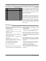
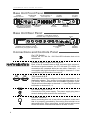
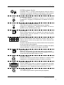
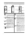
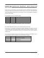
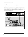
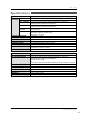
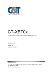
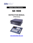
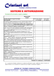
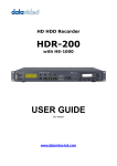
8 WAY INTERCOM
TALK BACK SYSTEM
ITC-100
Instruction Manual
w w w. d a t a v i d e o . c o m
INTERCOM TALK BACK SYSTEM
Welcome to the ITC-100 Instruction Manual
Thank you for choosing a Datavideo product, please visit the support
pages on our website for the latest version of the instruction manual.
http://www.datavideo.info/Intercom+Systems/ITC-100
Don’t forget to register your product online to qualify for an additional
free one year extension to the standard warranty, and to receive
information from Datavideo on service & information relevant to your
Datavideo product including new software updates & drivers
Warranty
Standard Warranty
• Datavideo equipment is guaranteed
against any manufacturing defects for one
year from the date of purchase.
• The original purchase invoice or other
documentary evidence should be supplied
at the time of any request for repair under
warranty.
• Damage caused by accident, misuse,
unauthorized repairs, sand, grit or water is
not covered by this warranty.
• All mail or transportation costs including
insurance are at the expense of the
owner.
• All other claims of any nature are not
covered.
• Cables & batteries are not covered under
warranty.
• Warranty only valid within the country or
region of purchase.
• Your statutory rights are not affected.
Two Year Warranty
• All Datavideo products purchased after
01-Oct.-2008 qualify for a free one year
extension to the standard Warranty,
providing the product is registered with
Datavideo within 30 days of purchase.
For information on how to register please
visit www.datavideo-tek.com or contact
your local Datavideo office or authorized
Distributors
• Certain parts with limited lifetime
expectancy such as LCD Panels, DVD
Drives, Hard Drives are only covered for
the first 10,000 hours, or 1 year (whichever
comes first).
Any second year warranty claims must be
made to your local Datavideo office or one
of its authorized Distributors before the
extended warranty expires.
Disposal
For EU Customers only - the applicable take back scheme for
the recycling of electrical and electronic
WEEE Marking
This symbol on the product
indicates that it will not be
treated as household waste.
It must be handed over to
2
equipment. For more detailed information
about the recycling of this product, please
contact your local Datavideo office.
ITC-100
Contents
Warnings and Precautions
3
Welcome to the ITC-100 Instruction Manual
4
Warranty4
Standard Warranty
4
Two Year Warranty
4
Disposal4
Packing List
5
Features5
Product Overview
5
Base Unit Front Panel
6
Base Unit Rear Panel
6
Connections and Controls Panel
6
ITC-100SL Belt Pack 8
Cable Assignments Headset, Jack plug and 5pin XLR
9
Pin Assigment for ITC-100 XLR Cable 9
ITC-100SL Belt pack 3.5mm Jack socket Headset connector
9
Using the ITC-100 with the SE-500
10
Using the ITC-100 with the SE-2000
11
Using the ITC-100 with the SE-2800
12
Using the ITC-100 with the SE-3000
13
ITC-100 Tally Input - Pin Cross Reference
14
Tally A Input
14
Tally B Input
14
Specifications
15
Service & Support
16
Disclaimer of Product and Services
The information offered in this instruction manual is intended as a guide only. At all times, Datavideo Technologies will
try to give correct, complete and suitable information. However, Datavideo Technologies cannot exclude that some
information in this manual, from time to time, may not be correct or may be incomplete. This manual may contain
typing errors, omissions or incorrect information. Datavideo Technologies always recommend that you double check
the information in this document for accuracy before making any purchase decision or using the product. Datavideo
Technologies is not responsible for any omissions or errors, or for any subsequent loss or damage caused by using the
information contained within this manual. Further advice on the content of this manual or on the product can be obtained
by contacting your local Datavideo Office or dealer.
Instruction Manual
3
INTERCOM TALK BACK SYSTEM
Warnings and Precautions
1.Read all of these warnings and save them
for later reference.
2.Follow all warnings and instructions
marked on this unit.
3.Unplug this unit from the wall outlet before
cleaning. Do not use liquid or aerosol
cleaners. Use a slightly damp cloth for
cleaning.
4.Do not use this unit in or near water.
5.Do not place this unit on an unstable
surface, cart, stand, or table. The unit
may fall, causing serious damage.
6.Any slots and openings on the case
top, back, and bottom are provided for
ventilation. To ensure safe and reliable
operation of this unit, and to protect it
from overheating, do not block or cover
these openings. Do not place this unit
on a bed, sofa, rug, or similar surface,
as the ventilation openings may become
blocked. This unit should never be placed
near or over a heat source or radiator.
This unit should not be placed in a builtin installation unless proper ventilation is
provided.
7.This product should only be operated from
the type of power source indicated on the
marking label of the AC adapter. If you are
not sure of the type of power available,
consult your Datavideo dealer or your
local power company.
8.Do not allow anything to rest on the power
cord. Do not locate this unit where the
power cord will be walked on, rolled over,
damaged or otherwise stressed.
9.If an extension cord must be used with
this unit, make sure that the total of the
ampere ratings on the products plugged
into the extension cord do not exceed the
extension cord’s rating.
10.Make sure that the total amperes of all
the units that are plugged into a single
wall outlet do not exceed 15 amperes.
4
11.Never push objects of any kind into this
unit through the case ventilation slots,
as they may touch dangerous voltage
points or short out parts that could result
in risk of fire or electric shock. Never spill
liquid of any kind onto or into this unit.
12.Except as specifically explained
elsewhere in this manual, do not attempt
to service this product yourself. Opening
or removing covers that are marked
“Do Not Remove” may expose you
to dangerous voltage points or other
risks, and will void your warranty. Refer
all service issues to qualified service
personnel.
13.Unplug this product from the wall outlet
and refer to qualified service personnel
under the following conditions:
a.When the power cord is damaged or
frayed;
b.When liquid has spilled into the unit;
c.When the product has been exposed
to rain or water;
d.When the product does not operate
normally under normal operating
conditions. Adjust only those controls
that are covered by the operating
instructions in this manual; improper
adjustment of other controls may result
in damage to the unit and may often
require extensive work by a qualified
technician to restore the unit to normal
operation;
e.When the product has been dropped
or the case has been damaged;
f.When the product exhibits a distinct
change in performance, indicating a
need for service.
ITC-100
Packing List
Product Overview
Item
1
2
3
4
5
6
7
Description
ITC-100 Base Unit
ITC-100SL Belt Packs
ITC-100SL Carry Cases
CB-3 20m Cables 5pin XLR to XLR
MC-1 Starter Headset with microphone
TD-2 on-camera Tally LED Indicators
MC-2 XLR Gooseneck Microphone
Qty
1
4
4
4
4
1
1
8
9
10
11
LP-1 XLR Gooseneck Light
12V / 1A Power Supply Unit
CB-17 17cm Earphone cable
ITC-100 Instruction Manual
1
1
4
1
The ITC-100 is a 19” Rack Mount 8 Way
Intercom / Talkback System. It incorporates
tally indicators for each channel and
individual channel call buttons as well as a
call all channels button.
It is designed for communication use in a
live mixing environment and enables easy
bi-directional communication between the
director and other members of the crew.
It is a perfect accessory for Datavideo
SE-500, SE-2000, SE-2800 and SE-3000
vision mixers.
Features
■ITC-100 1U 19” Rackmountable Base
Unit for Director
• C o m b i n e d X L R a n d 1 / 4 ' ( 6 . 3 m m )
microphone input
• D y n a m i c / C o n d e n s e r m i c r o p h o n e
selection switch
• Jack Socket 1/4' (6.3mm) for Headphones
without microphone
• Jack Socket 3.5mm for Headset with
microphone
• Speaker with volume control knob
• Channel selection buttons 1 – 8 select to
talk to Belt Pack / Crew member
• ALL channels selection button
• Base Unit MUTE button
■Rear Panel 8x 5pin XLR connectors for
cable connection to ITC-100SL Belt Packs
■C B - 3 2 0 m 5 p i n X L R M a l e t o X L R
Female cables
• Allows cable runs of up to 200m to be
created by purchasing additional cables
■Rear Panel 2x15pin D Sub Tally Input
sockets (for tally comms from mixer or
tally box)
■ITC-100SL Belt Pack for Crew members
• Call Button for sending paging signal to
Base Unit
• Talk button press and hold down to
communicate with Base Unit / Director
• Headset volume control knob
• Bi-Colour Tally LED on Belt Pack unit
• TD-2 on camera Tally Indicator wired from
Belt Pack
Instruction Manual
5
INTERCOM TALK BACK SYSTEM
Base Unit Front Panel
POWER
ON/OFF SWITCH
HEADPHONE
SOCKET
CALL BUTTONS 1~8
PLUS CALL ALL
VOLUME
CONTROL
CALL
CONDENSER
MIC
2
3
XLR/ 1/4" MICROPHONE
INPUT WITH DYNANAMIC/
CONDENSOR SWITCH
LIGHT 12V
MUTE
5
HEADPHONE
SPEAKER
MUTE
4
ALL
DYNAMIC
POWER
VOLUME
1
MIC MODE
12V LIGHT
SOCKET
6
7
8
MIN
MIC/
HEADPHONE
MAX
ITC-100
MUTE
BUTTON
MIC/HEADSET
SOCKET
8 WAY INTERCOM SYSTEM
BUILT-IN
SPEAKER
Base Unit Rear Panel
CHANNEL 1~4 XLR INPUT/ OUTPUT
SOCKETS Tally is suppplied from Tally A
B
DC IN
A
TALLY B
INPUT
8
7
6
5
4
3
2
TALLY A
INPUT
DC IN
12V 8W
1
+
CHANNEL 5~8 XLR INPUT/ OUTPUT
SOCKETS Tally is suppplied from Tally B
TALLY INPUTS
A&B
-
GROUND
TERMINAL
Connections and Controls Panel
On / Off Switch
Powers the ITC-100 On / Off. Red LED indicates that unit is
switched on.
B
8
7
Channel Input / Output XLR Sockets
A
6
5
4
3
TALLY B
INPUT
2
TALLY A
INPUT
1
Each of the 8 channels has an XLR connector that carries bidirectional signals between the ITC-100 and ITC-100SL. All
connections are contained within the one cable. Channels 1 ~ 4
are supplied tally light information from tally A; channels 5 ~ 8 are
supplied tally light information from tally B.
Tally Inputs A & B
Tally Inputs A & B are configured for direct connection to the
Datavideo switcher. They supply bi-color tally information to the
ITC-100SL; RED indicates Live and AMBER indicates Cued.
Tally A will feed information to channels 1 ~ 4 and Tally B will feed
information to channels 5 ~ 8
DC IN
12V 8W
+
-
DC Power Input 12V 8W
Connects the 12V power supply. The power supply plug has a
screw in locking collar to secure the connection.
Ground Terminal
When connecting this unit to any other component, make sure
that it is properly grounded by connecting this terminal to an
appropriate point. When connecting, use the socket and be sure
to use wire with a cross-sectional area of at least 1.0 mm².
6
ITC-100
XLR Microphone Socket
MIC MODE
Combined XLR / ¼” (6.3mm) Jack Microphone Input for either a
Condenser or Dynamic Gooseneck Microphone. XLR supports
Condenser Microphones ¼” (6.3mm) Jack supports Dynamic.
DYNAMIC
CONDENSER
MIC
Headphone Socket
¼ “ / 6.3mm Stereo Headphone Socket for conventional
headphones. Plugging in headphones will disable the built-in
speaker
Microphone / Headset Socket
3.5mm Stereo Socket for combined Microphone Headset.
Plugging in a Microphone / Headset will disable the built-in
speaker and the XLR Microphone Input.
ALL Button
ALL
Opens communication with all channels. All channels will hear
communication from the operator, or from any other channel
using the TALK button.
1
2
3
4
5
6
7
8
Channel Buttons 1~8
Opens communication with individual channels. More than 1
channel can be active at any given time, active channels are
illuminated red.
All active channels will hear any communication from the operator
or from any other active channel.
The buttons will also indicate if any channel is paging, the paging
channel will flash in orange until the page is answered.
MUTE Button
MUTE
VOLUME
MIN
MAX
SPEAKER
Mutes all communication from the base station or any channel.
N.B. If any channel uses the CALL button the paging tone will still
sound even when the MUTE button is active.
Volume Control
Controls the Volume of the built-in speaker or outputs to the
headphones or mic/headset according to what is connected
Built-In Speaker
Sounds audible alert when a channel is paging and provides
audio during talkback conversations. Speaker is mute when
headphones or mic / headset are connected to the ITC-100
LIGHT 12V
12V Light Socket
12V Powered light socket for gooseneck light (supplied).
Instruction Manual
7
INTERCOM TALK BACK SYSTEM
ITC-100SL Belt Pack
BASE
SIDE
TOP
Bi-Color Tally LED
TALLY
CALL
Call Button
TALK
Volume Control
Talk Button
ITC-100SL
VOL
OFF
TO MASTER UNIT
XLR Connection
Mic/ Headphone
Socket
EXT
TALLY
LED
POWER
XLR Connection
Connects the ITC-100SL to the
ITC-100 Base Unit. Power, tally
and bi-directional audio are all
carried through the same CB-3
cable.
Sends a paging message to the
ITC-100 Base Unit. The channel
button will flash orange and there
will be an audible tone, each
time the button is pressed.
TALLY
TALK
VOL
OFF
Illuminates RED when the
channel is LIVE and AMBER
when the channel is CUED
Talk Button
Volume Control
Adjusts the volume of the
headphones.
Power LED
The ITC-100SL has both a 3.5mm
and 2.5mm Mic / Headset socket.
A standard 3.5mm Mic / Headset
can be used, or a Motorola type
2.5mm Mic / headset could be
used if preferred.
External Tally LED Socket
EXT
TALLY
LED
Bi-Color Tally LED
Opens up talk back
communication with the ITC-100
Base Unit, and any other active
channels.
EXT Tally LED
Socket
Mic / Headphone Socket
MIC/
HEADPHONE
Call Button
CALL
8
MIC/
HEADPHONE
POWER
An external tally display (TD-2)
can be connected to the ITC-100SL.
This enables the tally light to be
positioned in a more convenient
place, such as on top of the
camera. When the channel is LIVE
the LED will be RED, and when
the channel is CUED the LED will
be AMBER.
N.B. The Tally LED on the ITC100SL will continue to operate as
normal when a TD-2 has been
added.
Power LED
The Power LED indicates when
the channel is active. If the
operator has opened the channel
by pressing the channel button
1 ~ 8, or by pressing ALL then the
LED will light up.
N.B. The tally indicator lights will
continue to work even when the
Power LED is not on, and the
channel is not active.
ITC-100
Cable Assignments Headset, Jack plug and
5pin XLR
Please Note: If you only want to extend the reach of the ITC-100SL Belt Pack cabling then
Datavideo already sell pre-manufactured XLR cabling for doing this in 20m (CB-3) and
50m (CB-4) lengths. Please ask your local dealer for price and availability of additional
CB-3 and CB-4 cables.
Pin Assigment for ITC-100 XLR Cable
Pin
1
2
3
4
5
Cable
Red
Black
Shield
Green
White
Assignment
Tally Red
Tip (Talk & Call)
Common with Ground of XLR
+12V DC power to ITC100SL
Tally Yellow
5pin XLR Cable is a straight through cable pin 1 to pin 1, pin 2 to pin 2 etc.
ITC-100SL Belt pack 3.5mm Jack socket Headset connector
Please Note: For connecting a professional headset, Datavideo can supply a mini jack
to XLR adaptor cable which would support headsets with a Dynamic microphone. Please
contact your dealer or local Datavideo office for more information on this XLR to Jack plug
adaptor cable.
In the case of a professional headset with an Electret microphone a small SDM of 1yf/1uf
(for decoupling ac) will be required on the Jack Tip/XLR pin 2 cabling.
Jack
Tip
Headset XLR Assignment
Pin 2
Microphone
(can be Dynamic or Electret)
Ring
Pin 4
Earphone (Impedance range 8-100Ω)
(ideally 30-40Ω)
Ground/Sleeve Pins 1 & 3
Common with Ground
Instruction Manual
9
INTERCOM TALK BACK SYSTEM
Using the ITC-100 with the SE-500
The ITC-100 is an ideal accessory for the Datavideo SE-500 Video Mixer. The SE-500 has
four channels, each channel can connect to the ITC-100SL.
By using Datavideo G07690150018 cable, the Tally output from the SE-500 connects to
the ITC-100 Tally Input A. Tally Input A provides tally information to channel 1 ~ 4. When
the camera is live the cameraman will see a tally light in red, when the camera is cued up,
the cameraman will see a tally light in amber.
SD 4-Channel Digital Video Switcher SE-500
TALLY
Microphone
Headset
G07690150018 Cable
Tally Light
Indicator
TD-2
Intercom Belt Pack
ITC-100SL
A
A
TALLY B
INPUT
Intercom System ITC-100
10
TALLY A
INPUT
ITC-100
Using the ITC-100 with the SE-2000
The ITC-100 is an ideal accessory for the Datavideo SE-2000 Video Mixer. The SE-2000
has four channels, each channel can connect to the ITC-100SL.
By using Datavideo G07690150018 cable, the Tally output from the SE-2000 connects to
the ITC-100 Tally Input A. Tally Input A provides tally information to channel 1 ~ 4. When
the camera is live the cameraman will see a tally light in red, when the camera is cued up,
the cameraman will see a tally light in amber.
HD 5-Channel Digital Video Switcher SE-2000
TALLY
G07690150018 Cable
Microphone Tally Light
Headset
Indicator
TD-2
Intercom Belt Pack
ITC-100SL
A
A
TALLY B
INPUT
TALLY A
INPUT
Intercom System ITC-100
Instruction Manual
11
INTERCOM TALK BACK SYSTEM
Using the ITC-100 with the SE-2800
The ITC-100 is an ideal accessory for the Datavideo SE-2800 Video Mixer. The SE-2800
has eight channels, each channel can connect to the ITC-100SL.
By using Datavideo G07690250002 cable, the, the Tally output from the SE-2800 connects
to the ITC-100 Tally Input A & Tally Input B. Tally Input A provides tally information to
channel 1 ~ 4, Tally Input B provides tally information to channel 5 ~ 8. When the camera
is live the cameraman will see a tally light in red, when the camera is cued up, the
cameraman will see a tally light in amber.
HD/SD 12-Channel Digital Video Switcher SE-2800
TALLY OUT
G07690250002 Cable
Microphone Tally Light
Indicator
Headset
TD-2
Intercom Belt Pack
ITC-100SL
B
A
Intercom System ITC-100
12
B
A
TALLY B
INPUT
TALLY A
INPUT
ITC-100
Using the ITC-100 with the SE-3000
The ITC-100 is an ideal accessory for the Datavideo SE-3000 Video Mixer. The SE-3000
has sixteen channels, each channel can connect to the ITC-100SL.
By using Datavideo G07690370003 cable, the Tally output from the SE-3000
c o n n e c t s t o t h e I T C - 1 0 0 Ta l l y I n p u t A & Ta l l y I n p u t B , a n d a l s o c o n n e c t s
to the ITC-200E Tally Input C & Tally Input D. Tally Input A provides tally
information to channel 1 ~ 4, Tally Input B provides tally information to channel
5 ~ 7, ITC-100 channel 8 connects to ITC-200E channel 1 by XLR Cable, So
ITC-100 channel 8 and ITC-200E channels1~8 are the same signal. When the camera
is live the cameraman will see a tally light in red, when the camera is cued up, the
cameraman will see a tally light in amber.
TALLY
HD/SD 16-Channel Digital Video Switcher SE-3000
G07690370003 Cable
Microphone Tally Light
Indicator
Headset
TD-2
Intercom Belt Pack
ITC-100SL
B
A
B
TALLY B
INPUT
A
TALLY A
INPUT
Intercom System ITC-100
XLR Cable
D
TALLY D
INPUT
C
TALLY C
INPUT
Intercom Expansion Unit ITC-200E
D
C
Instruction Manual
13
INTERCOM TALK BACK SYSTEM
ITC-100 Tally Input - Pin Cross Reference
If you are using the ITC-100 with a Datavideo product you do not need to worry about tally
information, as it is automatically sent to the ITC-100. If you are using the ITC-100 with
other equipments the following tables may help explain the pin configurations of the ITC100 Tally A and Tally B input.
Contact closure between the relevant Pin number and ground will illuminate the Tally LED.
For example on Tally A, if Pin 1 is connected to Pin 4 the RED LED will light up on Channel 1;
if Pin 13 is connected to Pin 4 the AMBER LED will light up on Channel 3
Tally A Input
The Tally A Input will send Tally Information to Channels 1 ~ 4. The following table shows
the pin numbers for each channel:
Video Channel Red LED LIVE (On Air)
1
Pin 1
2
Pin 6
3
Pin 11
4
Pin 5
Amber LED CUED (Next)
Pin 3
Pin 8
Pin 13
Pin 15
Pins 4, 9 and 14 can be used as ground.
Tally B Input
The Tally B Input will send Tally Information to Channels 5 ~ 8. The following table shows
the pin numbers for each channel:
Video Channel Red LED LIVE (On Air)
5
Pin 1
6
Pin 6
7
Pin 11
8
Pin 5
Pins 4, 9 and 14 can be used as ground.
14
Amber LED CUED (Next)
Pin 3
Pin 8
Pin 13
Pin 15
ITC-100
Specifications
ITC-100 Base Unit
Specification
INPUTS
/ OUTPUTS
WEIGHT
12V / 1A (8W)
2 x 15 Pin D-Sub Sockets for Tally A and Tally B
3.5mm Stereo Jack Socket for combination Headphone / Microphone
Headset Impedance 8~600 ohms 100mW(min)
¼” (6.3mm) Stereo Headphone Socket
Headset Impedance 8~600 ohms 100mW(min)
3 pin XLR connector. Pin2: 12V, Pin3: GND. Light power consumption
12V/100mA(max).
3 Pin XLR / ¼” (6.3mm) Jack Microphone Socket
Switchable Condenser / Dynamic Input
Microphone Level -67dB
550-3.6KHz, < +/-3dB
< 3%
> 50dB
70mm x 30mm 32 Ohm 3 Watts
Up to 200m between Base Station and Slave
5 ~ 45°C
(1U height 19” rack)
W: 440mm x D: 130mm x H: 40mm
1.9Kg
ITC-100SL Belt Pack Unit
Specification
INPUT
MIC / HEADSET SOCKET
5 Pin XLR Connector
3.5mm Stereo Jack Socket for combination Headphone / Microphone
Headset Impedance 8~600 ohms 100mW(min)
Microphone Level -67dB
Or
2.5mm Stereo Jack Socket, for Motorola Mobile Phone type headset / microphone
3.5mm Jack Socket to connect to TD-1 Tally Indicator
Bi-Color LED – RED indicates LIVE / AMBER Indicates CUED
Illuminates to indicate that power is being received
Up to 200m between Base Station and Slave
5 ~ 45°C
114mm x 97mm x 35mm
348g
POWER
TALLY
MIC / HEADSET
HEADPHONE
LIGHT SOCKET
(12V DC)
MICROPHONE
FREQUENCY RESPONSE
THD
S/N
BUILT-IN SPEAKER
OPERATING RANGE
OPERATING TEMP. RANGE
DIMENSION
TALLY OUT SOCKET
TALLY LED
POWER LED
OPERATING RANGE
OPERATING TEMP. RANGE
DIMENSION
WEIGHT
Instruction Manual
15
Service & Support
It is our goal to make your products ownership a satisfying experience. Our
supporting staff is available to assist you in setting up and operating your
system. Please refer to our web site www.datavideo.com for answers to
common questions, support requests or contact your local office below.
Datavideo USA
Datavideo The Netherland
Datavideo Corporation
7048 Elmer Avenue.
Whittier, CA 90602,
U.S.A.
Tel:+1-562-696 2324
Fax:+1-562-698 6930
E-mail:[email protected]
Datavideo Technologies Europe BV
Floridadreef 106
3565 AM Utrecht,
The Netherlands
Tel:+31-30-261-96-56
Fax:+31-30-261-96-57
E-mail:[email protected]
Datavideo Taiwan
Datavideo China
Datavideo Technologies Co. Ltd
10F. No. 176, Jian 1st Rd.,Chung Ho
District, New Taipei City 235, Taiwan,
R.O.C.
Tel: +886-2-8227-2888
Fax: +886-2-8227-2777
E-mail:[email protected]
Datavideo Hong Kong
Datavideo Hong Kong Ltd
G/F.,26 Cross Lane
Wanchai, Hong Kong
Tel: +852-2833-1981
Fax: +852-2833-9916
E-mail:[email protected]
Datavideo United Kingdom
Datavideo UK Limited
Units1 & 2 Waterside Business Park
Hadfield, Glossop, Derbyshire
SK13 1BE, UK
Tel:+44-1457 851 000
Fax:+44-1457 850 964
E-mail:[email protected]
Datavideo Singapore
Datavideo Technologies China Co
101,NO.618,LiuYing Rd,Zhabei District,
Shanghai,China
Datavideo Technologies (S) PTE Ltd
No. 178 Paya Lebar Road #06-03
Singapore 409030
Tel: +86 21-5603 6599
Fax: +86 21-5603 6770
E-mail:[email protected]
Tel:+65-6749 6866
Fax:+65-6749 3266
E-mail:[email protected]
Datavideo France
Datavideo France s.a.r.l
Cité Descartes 1,rue Albert Einstein
Champs sur Marne
774477-Marne la Vallée cedex 2
Tel:+33-1-60370246
E-mail: [email protected]
Datavideo India
Datavideo Technologies India Pvt Ltd
A-132, Sec-63,Noida-201307,
Uttar Pradesh (UP), India.
Tel:+91-0120-2427337
Fax:+91-0120-2427338
E-mail: [email protected]
www.datavideo.com
All the trademarks are the properties of their respective owners. Datavideo Technologies
Co., Ltd. All rights reserved 2018
Jan-10.2014 P/N: G082060402E9