1
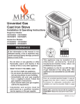
UNVENTED GAS
CAST IRON STOVE
INSTALLATION AND OPERATING
INSTRUCTIONS
SINGLE DOOR MODELS:
CSVF20SNV CSVF30SNV
CSVF20SPV CSVF30SPV
DOUBLE DOOR MODELS:
VFCS20DNV VFCS30DNV
VFCS20DPV VFCS30DPV
Natural Gas or
Propane/LPG
Millivolt Control
WARNINGS
WARNINGS
If the information in this manual is not followed
exactly, a fire or explosion may result causing
property damage, personal injury or loss of life.
This appliance may be installed in
an aftermarket, permanently located,
manufactured (mobile) home, where
not prohibited by local codes.
This appliance is only for use
with the type of gas indicated on
the rating plate. This appliance is
not convertible for use with other
gases.
This is an unvented gas-fired heater.
It uses air (oxygen) from the room
in which it is installed. Provisions for
adequate combustion and ventilation
air must be provided. Refer to page 8.
– Do not store or use gasoline or other flammable
vapors and liquids in the vicinity of this or any
other appliance.
– WHAT TO DO IF YOU SMELL GAS
• Do not try to light any appliance.
• Do not touch any electrical switch; do not use
any phone in your building.
• Immediately call your gas supplier from a
neighbor's phone. Follow the gas supplier's
instructions.
• If you cannot reach your gas supplier, call the
fire department.
– Installation and service must be performed by
a qualified installer, service agency or the gas
supplier.
READ AND SAVE THESE INSTRUCTIONS
CONTENTS
Important Safety Information........................... 3
Rock Wool Installation.................................... 18
Product Features............................................... 5
Flame Appearance........................................... 19
Checking Pilot Flame................................... 19
Checking the Burner Flame......................... 20
Dimensions........................................................ 6
Getting Started................................................... 7
Product Specifications..................................... 8
Ignition Controls............................................. 8
Pilot................................................................ 8
Thermal Generator........................................ 8
General Installation Information...................... 9
Codes............................................................ 9
Adequate Combustion and Ventilation Air..... 9
Clearances / Height Requirements................ 11
Removing Unit from Crate.............................. 13
Connecting the Gas......................................... 14
Checking Gas Pressure.................................. 15
Operating Instructions.................................... 21
For Your Safety Read Before Lighting......... 21
Millivolt Control Lighting Instructions........... 22
To Turn Off Gas to Heater............................ 22
Match Lighting Instructions.......................... 23
Cleaning and Servicing................................... 23
Replacement Parts List................................... 24
VF20 Logs and Burner Assembly................ 24
VF30 Burner Assembly................................ 26
VFCS 30 Logs.............................................. 28
Troubleshooting.............................................. 29
Warranty........................................... Back Cover
Connecting Remote Receiver........................ 15
Electrical Wiring.............................................. 16
Connecting Optional Wall Switch or Checking
System Operation........................................ 16
Log Placement................................................. 17
Installing Logs on Grate............................... 18
58D6002
IMPORTANT SAFETY INFORMATION
INSTALLER
OWNER
Please leave these instructions with the appliance.
Please retain these instructions for future reference.
IMPORTANT
warning
Read these instructions carefully before installing or trying to operate this vent-free gas heater.
• Any change to this heater or its controls can be dangerous.
• Improper installation or use of the heater can cause serious injury or death from fire,
burns, explosion or carbon monoxide poisoning.
• Do not allow fans to blow directly into the stove. Avoid any drafts that alter burner
flame patterns.
• Do not use a blower insert, heat exchanger insert or other accessory, not approved
for use with this heater where applicable.
1.Due to high temperatures, the appliance should be
located out of traffic and away from furniture and draperies.
2.Children and adults should be alerted to the hazard of
high surface temperature and should stay away to avoid
burns or clothing ignition.
3.Young children should be carefully supervised when they
are in the same room with the appliance.
4.Do not place clothing or other flammable material on or
near the appliance.
5.Any safety screen or guard removed for servicing an appliance, must be replaced prior to operating the heater.
6.Installation and repair should be done by a qualified service person.
7. To prevent malfunction and/or sooting, an unvented gas
heater should be cleaned before use and at least annually
by a professional service person. More frequent cleaning
may be required due to excessive lint from carpeting,
bedding material, etc. It is imperative that control compartments, burners and circulating air passageways be
kept clean.
8. CARBON MONOXIDE POISONING: Early signs
of carbon monoxide poisoning are similar to the
flu with headaches, dizziness and/or nausea. If
you have these signs, obtain fresh air immediately.
Have the heater serviced as it may not be operating
properly.
9. The installation must conform with local codes
or, in the absence of local codes, with the National
Fuel Gas Code, ANSI Z223.l/NFPA54.
10. This unit complies with ANSI Z21.11.2-2001
Unvented Heaters.
11. Do not install heater in a bathroom or bedroom
unless approved for bedroom use.
12. Correct installation of the ceramic fiber logs, proper
location of the heater, and annual cleaning are
necessary to avoid potential problems with sooting. Sooting, resulting from improper installation
or operation, can settle on surfaces outside the
fireplace. See log placement instructions for proper
installation.
13. Avoid any drafts that alter burner flame patterns.
Do not allow fans to blow directly into fireplace. Do
not place a blower inside burn area of firebox. Ceiling fans may create drafts that alter burner flame
patterns. Sooting and improper burning will occur.
Continued on page 4
58D6002
IMPORTANT SAFETY INFORMATION
Continued from page 3
14. Caution: Candles, incense, oil lamps, etc. produce
combustion by-products including soot. Vent-free
appliances will not filter or clean soot produced by
these types of products. In addition, the smoke
and/or aromatics (scents) may be reburnt in the
vent-free appliance which can produce odors. It
is recommended to minimize the use of candles,
incense, etc. while the vent-free appliance is in
operation.
15. This is an unvented gas-fired heater. It uses air
(oxygen) from the room in which it is installed. Provisions for adequate combustion and ventilation air
must be provided. See page 8.
16. Keep room area clear and free from combustible
materials, gasoline and other flammable vapors
and liquids.
17. Unvented gas heaters are a supplemental zone
heater. They are not intended to be a primary heating appliance.
18. Unvented gas heaters emit moisture into the living
area. In most homes of average construction, this
does not pose a problem. In houses of extremely
tight construction, addition mechanical ventilation
is recommended.
19. During manufacturing, fabricating and shipping,
various components of this appliance are treated
with certain oils, films or bonding agents. These
chemicals are not harmful but may produce annoying smoke and smells as they are burned off during
the initial operation of the appliance; possibly causing headaches or eye or lung irritation. This is a
normal and temporary occurrence.
The initial break-in operation should last two to three
hours with the burner at the highest setting. Provide
maximum ventilation by opening windows or doors
to allow odors to dissipate. Any odors remaining
after this initial break-in period will be slight and will
disappear with continued use.
20. Input ratings are shown in BTU per hour and are for
elevations up to 2,000 feet. For elevations above
2,000 feet, input ratings should be reduced 4 percent for each 1,000 feet above sea level. Refer to
the National Fuel Gas Code.
21. The appliance and its appliance main gas valve
must be disconnected from the gas supply piping
system during any pressure testing of that system
at test pressures in excess of 1/2 psig (3.5 kPa).
22. The appliance must be isolated from the gas supply
piping system by closing its equipment shutoff valve
during any pressure testing of the gas supply piping
system at test pressures equal to or less than 1/2
psig (3.5 kPa).
58D6002
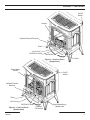
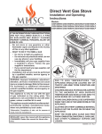
product features
On/Off
Switch
Handle
Optional Remote Receiver
Piezo
Hi/Lo Knob
Off/Pilot/On Knob
Fan Switch
Figure 1 - Cast Iron Stove
(Single Door)
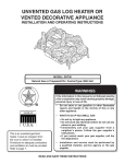
Break-Away
Handle
Door
On/Off
Switch
Optional Remote
Receiver
Piezo
Hi/Lo Knob
Off/Pilot/On Knob
Figure 2 - Cast Iron Stove
(Double Door)
58D6002
Optional
Fan Switch
Store Break-Away
Handle Here
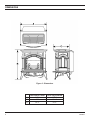
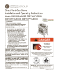
dimensions
Figure 3 - Dimensions
A
B
C
CSVF20S/VFCS20D
211/4"
23"
161/2"
CSVF30S/VFCS30D
263/4"
281/2"
193/4"
58D6002
getting Started
Make sure you have received all parts:
Check your packing list to verify that all listed parts have been received. You should have the following:
• Cast Iron Stove with Burner Assembly
• Installation/Operating Instructions
• Ceramic Fiber Logs
• Touch-up Paint
Millivolt controlled heater designed to be operated with optional devices for ON/OFF functions.
• Hand-Held Remote with Manual Receiver
caution
• Wall Switch with 15' Wire
Gloves are recommended when handling ceramic fiber logs to prevent skin irritation
from loose fibers. Logs are fragile — handle with care.
Carefully inspect the contents for shipping damage. If any parts are missing or damaged, immediately inform the
dealer from whom you purchased the appliance. Do not attempt to install any part of the appliance unless
you have all parts in good condition.
What you will need for installation:
You must have the following items available before proceeding with installation:
• External regulator (for propane/L.P.G.)
or high pressure natural gas (1 to 2 PSI system)
• Piping which complies with local codes
• Sediment trap (recommended)
• Pipe wrench or appropriate wrench set
58D6002
• Pipe sealant approved for use with propane/
L.P.G.
(Resistant to sulfur compounds)
• Manual shutoff valve
• Tee joint
• Screwdrivers
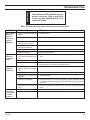
PRODUCT SPECIFICATIONS
Natural Gas
NOTE: An external regulator is required to reduce supply pressure to a maximum of 101/2" w.c. on Natural Gas
systems operating at higher pressure. Millivolt Pressure
Regulator Pressure Setting: 3.5" w.c.
Pilot Regulator:
3.5" w.c.
Gas Inlet Pressure: Max. 10 1/2" w. c.
Min. 5" w.c.
Gas Rate
Model Number
CSVF20SNV/VFCS20DNV (G-EBL-ES-EMB)
CSVF30SNV/VFCS30DNV (G-EBL-ES-EMB)
Type
Millivolt
Millivolt
Max. BTU/Hr
Min. BTU/Hr
10,000
32,000
6,000
20,000
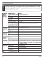
Propane / LPG
Note: An external regulator is required to reduce supply pressure to a maximum of 13" w.c.
Millivolt Pressure
Regulator Pressure Setting: 10" w.c.
Gas Inlet Pressure: Maximum 13" w.c.
Minimum 11" w.c.
Gas Rate
Model Number
CSVF20SPV/VFCS20DPV (G-EBL-ES-EMB)
CSVF30SPV/VFCS30DPV (G-EBL-ES-EMB)
Type
Millivolt
Millivolt
Max. BTU/Hr
Min. BTU/Hr
10,000
32,000
6,000
20,000
Ignition controls
Piezo ignitor allows ignition of the pilot without the use of matches.
Millivolt control has four (4) positions:
OFF
- All gas to the burner is shut off at the valve.
IGN
- Valve position to light/maintain a standing pilot.
ON
- Valve position to turn burners ON/OFF with remote switch.
LOW/HI - Variable position to control flame height (heat output). Both front and rear burners are in
operation to provide realistic glow and yellow flame.
Pilot/ODS
The gas log heater is fitted with a specially designed safety pilot (ODS assembly) light which senses the amount
of oxygen available in the room and shuts the gas log heater off if the oxygen level begins to drop below a satisfactory level. The pilot can only be relit when adequate fresh air is available.
Thermal Generator
The millivolt gas log pilot is fitted with a millivolt thermopile generator to provide power for remote activation.
58D6002
warning
GENERAL INSTALLATION INFORMATION
Do not install the heater …
• Where curtains, furniture, clothing, or other flammable objects are less than 42" from
the front of the heater.
• In high traffic areas.
• In windy or drafty areas.
CODES
Adhere to all local codes or, in their absence, the latest edition of THE NATIONAL FUEL GAS CODE ANSI Z223.1
or NFPA54 which can be obtained from…
American National Standards Institute, Inc.
1430 Broadway
New York, NY 10018
or
National Fire Protection Association, Inc.
Batterymarch Park
Quincy, MA 02269
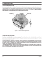
ADEQUATE COMBUSTION AND VENTILATION AIR
This heater shall not be installed in a confined space or unusually tight construction unless provisions are provided
for adequate combustion and ventilation air.
The National Fuel Gas Code, (ANSI Z223.1/NFPA54), defines a confined space as a space whose volume is
less than 50 cubic feet per 1,000 BTU per hour (4.8 m3 per kw) of the aggregate input rating of all appliances
installed in that space and an unconfined space as a space whose volume is not less than 50 cubic feet per
1,000 BTU per hour (4.8 m3 per kw) of the aggregate input rating of all appliances installed in that space. Rooms
communicating directly with the space in which the appliances are installed, through openings not furnished with
doors, are considered a part of the unconfined space.
Unusually tight construction is defined as construction where…
a) walls and ceilings exposed to the outside atmosphere have a continuous water vapor retarder with a rating of 1 perm
(6 x 10¹¹ kg per pa-sec-m2) or less with openings gasketed or sealed;
b) weather stripping has been added on openable windows and doors, and
c) caulking or sealants are applied to areas such as joints around window and door frames, between sole
plates and floors, between wall-ceiling joints, between wall panels, at penetrations for plumbing, electrical,
and gas lines, and at other openings.
58D6002
GENERAL INSTALLATION INFORMATION
Counter
Cast Iron Stove
Figure 4 - Example of a Large Room with 1/2 Wall Divider
The following formula can be used to determine the maximum heater rating per the definition of unconfined
space:
BTU/Hr = (L1 + L2) Ft x (W) Ft x (H) Ft
50
x 1000
Consider two connecting rooms with an open area between, with the following dimensions:
L1 = 151/2 Ft., L2 = 12 Ft., W = 12 Ft., H = 8 Ft.
BTU/Hr = (151/2 + 12) x (12) x (8)
50
x 1000 = 52800 BTU/Hr
If there were a door between the two rooms the calculation would be based only on the room with the heater.
warning
BTU/Hr = (151/2) x (12) x (8)
50
10
x 1000 = 29760 BTU/Hr
If the area in which the heater may be operated is smaller than that defined as an
unconfined space or if the building is of unusually tight construction, provide adequate
combustion and ventilation air by one of the methods described in the National Fuel
Gas Code, ANSI Z223.1, NFPA54, Section 5.3 or applicable local codes.
58D6002
warning
CLEARANCES / HEIGHT REQUIREMENTS
The dimensions shown in Figure 5 are minimum clearances to maintain in installing this
heater. Left and right clearances are determined when facing the front of the heater.
Follow these instructions carefully to ensure safe installation. Failure to follow
instructions exactly can create a fire hazard.
The appliance cannot be installed on a carpet, tile or other combustible material other
than wood flooring, the appliance shall be installed on a metal, wood or noncombustible
material panel extending full width and depth of the appliance.
Ceiling
Ceiling
Side
Wall
Side
Wall
Mantel
Side View
Front View
Floor
Floor
Corner Installation
Wall Installation
Figure 5 - Minimum Clearance to Walls and Ceiling
Mantel Clearance from
Top of Unit
Corner
Measured
From Top
Corners
Min. Ceiling
from Floor
Max.
Protrusion
Min. Height
Right
Left
Rear
Measured
from Back
A
B
C
D
E
F
G
VF20
72"
12"
16"
1"
1"
½"
1½"
VF30
72"
12"
18"
2"
2"
1"
½"
Product
58D6002
Side, Measured from Top
11
CLEARANCES / HEIGHT REQUIRMENTS
Figure 6 - Placing Stove in Alcove
Tested Minimum Alcove Dimensions
VF20
VF30
Height From
Hearth
A
38½"
52"
Width
B
23"
34"
Depth
C
36"
36"
Note: Maintain minimum side and back clearances when placing stove in alcove.
12
58D6002
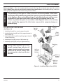
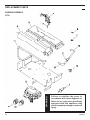
Removing Unit from Crate
1. Remove two (2) straps. See Figure 7.
2. Open plastic bag and slide to bottom of unit.
See Figure 8.
Plastic
Bag
Straps
3. Lift up on ash lip and pivot down to open
control door. See Figure 9.
4. Lift up on front. Pivot bottom of front out.
Remove front. See Figure 9.
5. Lift screen to remove.
6. Remove log box from inside of unit.
7. Lift unit off pallet. Lift unit up high enough to
clear upright supports unit is sitting on.
Note: You will need at least two (2) strong
people to lift unit off of pallet.
Pallet
Figure 7 - Removing Straps and Plastic from Unit
Hearth
Door
Log
Box
Ash Lip
Control
Door
Figure 8 - Opening Control Door and Removing
Hearth Door
58D6002
Figure 9 - Removing Log Box
13
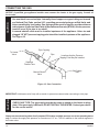
CONNECTING THE GAS
caution
NOTICE: A qualified gas appliance installer must connect the heater to the gas supply. Consult all
local codes.
Use new black iron or steel pipe. Internally tinned copper or copper tubing can be used
per National Fuel Code, section 2.6.3, providing gas meets hydrogen sulfide limits, and
where permitted by local codes. Gas piping system must be sized to provide minimum
inlet pressure (Listed on Data Plate) at the maximum flow rate (BTU/Hr). Undue pressure
loss will occur if the pipe is too small.
A manual shutoff valve must be installed upstream of the appliance. Union tee and
plugged 1/8" NPT pressure tapping point should be installed upstream of the appliance.
See Figure 10.
Pipe Coupling
To Heater
Valve
Pipe
Locations that the Pressure
Tapping Point May Be Installed
Stainless
Flexible Tube
Manual Shutoff
Valve
Gas Supply
Inlet
Figure 10 - Gas Connection
caution
IMPORTANT: Hold heater valve firmly with a wrench to prevent movement when connecting to inlet pipe.
Check gas type: The gas supply must be the same as stated on the heater’s rating
plate. If the gas supply is different, DO NOT INSTALL THE HEATER. Contact your dealer
for the correct model.
Always use an external regulator for all propane/LPG heaters and high pressure one to two-pound systems
only, to reduce the supply tank pressure to a maximum of 13" w.c. This is in addition to the internal regulator in
the heater valve.
14
58D6002
The heater gas inlet connection is 3/8" NPT at the valve.
The inlet is located on left side of stove. Remove front
control plate to better access the inlet.
When tightening up the joint to the valve, hold the valve
securely with a wrench to prevent movement.
warning
CHECKING GAS PRESSURE and connecting remote receiver
Connecting directly to an unregulated
propane/L.P.G. tank can cause an
explosion.
Test all gas joints from the gas meter to the heater valve
for leaks using a gas analyzer or soap and water solution after completing connection. DO NOT USE AN OPEN FLAME.
Millivolt Control (Figure 11)
Test Port “OUT”
The valve regulator controls the burner pressure which
should be checked at the pressure test point.
If outlet pressure is low, check inlet pressure against data
plates or manual.
Turn captured slotted screw counter clockwise 2 or 3
turns and then place tubing to pressure gauge over test
point (Use test point “OUT” closest to control knob). After
taking pressure reading, be sure and turn captured screw
clockwise firmly to re-seal. Do not over torque. Check for
gas leaks.
Figure 11 - Pressure Test Point Location
Millivolt Control
NOTE: Remove control panel to access gas valve.
Connecting Remote Receiver
1. Remove cover on control panel to show opening
for remote receiver. See Figure 12.
2. Follow remote receiver Instructions to make all
necessary wiring connections.
3. Place remote receiver in the opening of control
panel. Use two screws provided to attach remote
receiver to the control panel. See Figure 12.
Remote Receiver
NOTE: Do not place remote in combustion chamber.
Cover
Figure 12 - Installing Remote Receiver
58D6002
15
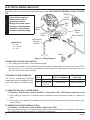
ELECTRICAL WIRING (Millivolt)
caution
The millivolt valve is a self-powered combination gas control that does not require 110 Vac to operate.
ODS Pilot
Label all wires prior to
disconnection when
servicing controls.
Wiring errors can cause
improper and dangerous
operation. Verify proper
operation after servicing.
On/Off
Switch
ODS
Pilot
Wall
Switch
On/Off
Switch
CONNECTION
1 = TP
2 = TP, TH
3 = TH
Optional Wall
Switch or
Remote
Millivolt
Valve
3
1
2
Spade Terminal
Switch
Figure 13 - Wiring Diagram
Connecting Optional Wall Switch
1. Use 18 awg, two-wire cable, 15 feet maximum length.
2. At one end of the cable, connect both wires to the wall switch. At the other end, connect one wire to TP/TH
and one wire to TH, or connect the wall switch to the two male (0.25") terminals on the left side of the unit.
The color of the wires does not matter.
Checking System Operation
The millivolt system and individual
components may be checked with a millivolt meter having a 0-1000mv range.
CHECK
TEST
TO TEST
CONNECT METER
LEADS TO TERMINALS
METER READING
SHOULD BE
A
COMPLETE
2 & 3 SYSTEM
MINIMUM 175mv
B
THERMOPILE
OUTPUT
1 & 2 SYSTEM
500mv OR MORE
A.Complete Millivolt System Check
("A" Reading - On/Off switch contacts CLOSED - Control Knob “ON” - Main Burners should turn ON)
a. If the reading is more than 175 millivolts and the automatic valve still does not come on - replace the
valve.
b. If the closed circuit reading ("A" reading) is less than 175 millivolts, determine cause for low reading - proceed as follows:
B.Thermopile Output Reading Check
(“B” Reading - On/Off switch contacts OPEN - Main burner OFF)
Check gas pressure to the unit. If gas pressure is within minimum and maximum on data plate, then replace
pilot. If the minimum millivolt reading is not obtainable, replace pilot.
16
58D6002
LOG PLACEMENT
warning
Before you begin — This unit is supplied with four ceramic fiber logs. Do not handle these logs with your bare
hands. Always wear gloves to prevent skin irritation from ceramic fibers. After handling the logs, wash your
hands gently with soap and water to remove any traces of fibers.
The positioning of the logs are critical to the safe and clean operation of this heater.
Sooting and other problems may result if the logs are not properly and firmly positioned
in the appliance. Never add additional logs or embellishments such as pine cones,
vermiculite or rock wool to the heater. Only use the logs supplied with the unit.
Failure to position the parts in accordance with diagrams below or to use only
parts specifically approved for this heater may result in property damage or
personal injury.
VF30 Installing logs on grate
(See Figure 14)
Top Left
Log #4
Right
Top Log
#5
1.Install back log (#1) on rear log support bracket.
2.Install left bottom log (#2) on left log support bracket in
front of back log.
3. Install right bottom log (#3) on right log support bracket
in front of back log.
Left
Bottom
Log #2
Right
Bottom
Log #3
4.Install top left log (#4) on top of left bottom log.
caution
5.Install top right log (#5) on top of right bottom log.
During initial operation of the new
heater, burning logs will give off
a paper burning smell and orange
flames will be present. Simply open
the windows for a few hours to vent
the odor.
Back Log
#1
Left Log
Support
Bracket
Rear Log
Support
Bracket
Right Log
Support
Bracket
Figure 14 - Installing Logs to Grate (VF30)
58D6002
17
LOG PLACEMENT
VF20 Installing logs on grate
(See Figure 15)
1.Install back log (#1) on back of burner assembly.
2.Install front log (#2) on 2 pegs on burner assembly.
Figure 15 - Installing Logs to Grate (VF20)
rock wool installation (VF30 Units only)
1. Break rock wool into dime-sized pieces.
➞
2. Place rock evenly across rock wool tray and front burner as
shown in Figure 16.
• Rock wool depth must not be more than 1".
• Do not place rock wool past the bend in rock wool tray.
warning
• Do not place rock wool on rear burner.
Rock wool must be placed
correctly. Placing rock wool
in wrong area will create high
carbon monoxide.
Bend in Rock
Wool Tray
Rock Wool
Rock Wood
Tray
Figure 16 - Rock Wool Installation
18
58D6002
flame appearance
Flames from the pilot, front and rear burner should be visually checked as soon as the heater is installed.
In addition, periodically check the flames visually during operation.
Checking pilot flame
The pilot flame must always be present when the heater is in operation. It should just touch the top of the
thermocouple tip for natural. See Figure 17 for correct pilot flame.
If the pilot flame does not touch the thermocouple, then the burners cannot function reliably. See Figure 18 for
incorrect shape of pilot flame.
Millivolt Control
Thermocouple
for Natural
Thermocouple
for LP
Figure 17 - Correct Appearance of Pilot Flame
58D6002
Thermocouple
for Natural
Thermocouple
for LP
Figure 18 - Incorrect Appearance of Pilot Flame
19
FLAME APPEARANCE
CHECKING BURNER FLAME
In normal operation at full rate after 15 minutes, the following flame appearances should be observed:
The left and right rear flames should be yellow and extend 1"-2" above middle logs. The yellow flames should
not contact the logs. There should be glowing embers on the front surface of the middle log. Note: The flames
and embers will be an opaque orange color during the burn off time.
Middle Log
Middle Log
Figure 19 - Correct Flame Appearance
OPERATING INSTRUCTIONS
Avoid any drafts that alter burner flame patterns. Do not allow fans to blow directly into the stove. Do not
place a blower inside the burn area of the stove. Ceiling fans may create drafts that alter flame patterns. Sooting
and improper burning will result.
During manufacturing, fabricating and shipping, various components of this appliance are treated with certain
oils, films or bonding agents. These chemicals are not harmful, but may produce annoying smoke and smells
as they are burned off during the initial operation of the appliance, possibly causing headaches or eye or lung
irritation. This is a normal and temporary occurrence.
The initial break-in operation should last two to three hours with the burner at the highest setting. Provide maximum ventilation by opening windows or doors to allow odors to dissipate. Any odors remaining after this initial
break-in will be slight and will disappear with continued use.
20
58D6002
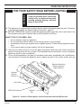
OPERATING INSTRUCTIONS
warning
for your safety read before lighting
If you do not follow these instruction
exactly, a fire or explosion may result
causing property damage, personal
injury or loss of life.
A. This appliance is equipped with an ignition device which automatically lights the pilot. If the piezo
is not working properly, see Match Lighting Instructions, page 24.
B. BEFORE OPERATING smell all around the appliance area for gas. Be sure to smell next to the
floor because some gas is heavier than air and will settle on the floor.
WHAT TO DO IF YOU SMELL GAS:
• Do not attempt to light any appliance.
• Do not touch any electric switch; do not use any phone in your building.
• Immediately call your gas supplier from a neighbor's phone. Follow the gas supplier's instructions.
• If you cannot reach your gas supplier, call the fire department.
C. Use only your hand to push in, or turn the gas control knob. Never use tools. If the knob will not
push in or turn by hand, don't try to repair it. Call a qualified service technician. Force or attempted
repair may result in a fire or explosion.
D. Do not use this appliance if any part of it has been under water. Immediately call a qualified service technician to inspect the appliance and to replace any part of the control system and any
Data and Instruction
Plates Located on
Back of Burner
Optional
Remote
Receiver
Hi/Lo Knob
Off/Pilot/On Knob
Optional
Fan
Figure 20 - Location of Piezo Ignitor, Control Knobs and Switch on Millivolt Unit
58D6002
21
OPERATING INSTRUCTIONS
Millivolt
CONTROL LIGHTING INSTRUCTIONS
1. STOP! Read the safety information label.
2. Make sure the manual shutoff valve is fully open.
3. This gas log set is equipped with an ignition device (piezo) which automatically lights the pilot.
If piezo ignitor does not light the pilot, refer to instructions for Match Lighting Instructions, page
23.
4. Turn gas control knob clockwise
to the OFF position, turn ON/OFF switch to OFF position.
5. Wait (5) minutes to clear out any gas. Then smell for gas, including near the floor. If you smell
gas, STOP! Follow the instructions under What To Do If You Smell Gas, page 21.
6. From OFF position, turn the gas control knob counterclockwise
to IGN position. Push
in control knob for 5 seconds. NOTE: If you are running the heater for the first time, it may
be necessary to press in the control knob for 30 seconds or longer to allow air to bleed
out of the gas piping.
7. With the control knob pushed in, push in and release the piezo ignitor button to light the pilot.
8. Continue pushing the control knob in for a further 10 seconds to prevent the flame detector from
shutting off the gas while the probe is warming up. Release the control knob.
9. Turn gas control knob counterclockwise
to the ON position.
10. After the pilot has been lit for one minute, the burners can be turned on. Turn the ON/OFF switch
to ON position.
11. If the gas logs will not operate, follow the instructions “To Turn Off Gas To Heater” below and
call your service technician or gas supplier.
Hi/Lo Control
Ignitor/Pilot Control
Figure 21 - Pilot
On/Off Switch
(Located on Side
of Stove)
Figure 22 - Control Cover Plate for Millivolt
TO TURN OFF GAS TO HEATER
1. Turn ON/OFF switch to OFF position.
2. Turn control knob clockwise
to OFF position to completely shut off the heater.
3. If applicable: Turn off all electric power to the heater.
22
58D6002
OPERATING INSTRUCTIONS and Cleaning and Servicing
match lightinG instructions
1. Open stove door. Remove any items necessary for easy access to the pilot (for example:
logs, screens, etc.).
2. Follow appropriate lighting instructions found previously. Light a match and hold the flame to
the end of the pilot and ignite the pilot.
3. After control knob has been released and pilot stays lit, reinstall any items that were removed
for pilot access. Close and latch stove door.
4. Call a qualified service technician for repair or replacement of the piezo ignitor.
CLEANING AND SERVICING
WARNING
Annual inspection and cleaning by your dealer or qualified service technician is recommended to prevent
malfunction and/or sooting.
Turn off heater and allow to cool before
cleaning. Disconnect electrical power
before cleaning or servicing.
Remove logs, handling carefully by holding gently at each end. Gloves are recommended to prevent skin irritation from ceramic fibers. If skin becomes irritated, wash gently with soap and water. Refer to manual for correct
log placement.
Periodic Cleaning - See parts diagram for location of items discussed below.
• Do not use cleaning fluid to clean logs or any part of heater.
• Brush logs with soft bristle brush or vacuum with brush attachment.
• Vacuum loose particles and dust from the front and rear burners, control and piezo covers and grate weldment.
• Inspect and clean burner air intake holes. Remove lint or particles with vacuum, brush, or pipe cleaners.
Failure to keep air intake holes clean will result in sooting and poor combustion.
• External case should be dusted and wiped with a moist cloth.
Annual Cleaning/Inspection - Refer to parts diagram for location of items discussed below.
• Inspect and clean burner air intake holes. Remove lint or particles with vacuum, brush or pipe cleaners.
Failure to keep air intake holes clean will result in sooting and poor combustion.
• Inspect and clean all burner ports.
• Inspect ODS pilot for operation and accumulation of lint at air intake holes.
• Verify flame pattern and log placement for proper operation.
• Verify smooth and responsive ignition of main burner and rear burner.
58D6002
23
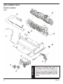
replacement parts
Burner assembly
warning
VF20
24
Failure to position the parts in
accordance with these diagrams or
failure to use only parts specifically
approved with this appliance may
result in property damage or personal
injury.
58D6002
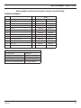
REPLACEMENT PARTS list
REPLACEMENT PARTS ARE AVAILABLE THROUGH YOUR RETAILER.
Burner assembly
VF20
Item Description
Qty
Natural
Propane
1
Piezo Igniter
1
14D0503
14D0503
2
VF Valve Tube
1
58D0519
58D0519
3
4
5
6
7
8
9
10
Piezo Wire
00K0632
00K0632
33D0070
33D0071
14D0467
14D0468
33D0280
33D0281
14D0473
14D0477
43D0094
43D0094
43D0095
43D0095
On/Off Switch
1
1
1
1
1
1
1
1
32D0232
32D0232
11
Rear Log
1
58D0527
58D0527
12
Front Log
1
58D0526
58D0526
Burner
Control Valve
Burner Injector
ODS Pilot Assembly
On/Off Control Knob
Hi/Lo Control Knob
Accessories
Flex Connector
Flexcon 18
Wall Switch Kit
MVWS
Wall Thermostat Kit
WT
Hand Held Remote
RCM/RCB/WMTD
Hand Held Thermostat Remote
RCT/RCST/WWTD
58D6002
25
replacement parts
Burner assembly
warning
VF30
26
Failure to position the parts in
accordance with these diagrams or
failure to use only parts specifically
approved with this appliance may
result in property damage or personal
injury.
58D6002
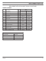
REPLACEMENT PARTS list
REPLACEMENT PARTS ARE AVAILABLE THROUGH YOUR RETAILER.
Burner assembly
VF30
Item Description
1
2
3
4
5
6
7
8
9
10
11
12
13
14
15
Piezo Ignitor
5/16 Union Tee
Piezo Wire
Front Burner
Rear Burner
Control Valve
Front Burner Injector
Rear Burner Injector
ODS Pilot Assembly
On/Off Control Knob
Hi/Lo Control Knob
On/Off Switch
VF Valve Tube
VF Rear Burner Tube
VF Front Burner Tube
Qty
Natural
Propane
1
1
1
1
1
1
1
1
1
1
1
1
1
1
1
14D0503
14D0503
43D0181
43D0181
00K0632
00K0632
58D0193
58D0435
58D0193
58D0435
14D0467
14D0468
58D0061
58D0061
58D0056
62D3005
14D0473
14D0477
43D0094
43D0094
43D0095
43D0095
32D0232
32D0232
58D0427
58D0428
58D0429
58D0427
58D0428
58D0429
Accessories
Flex Connector
Flexcon 18
Wall Switch Kit
MVWS
Wall Thermostat Kit
WT
Hand Held Remote
RCM/RCB/WMTD
Hand Held Thermostat Remote
RCT/RCST/WWTD
58D6002
27
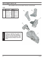
replacement parts list
REPLACEMENT PARTS ARE AVAILABLE THROUGH YOUR RETAILER.
Logs
Item
Description
Qty
VF30
Back Log 1
58D1901
2
Bottom Left Log
1
58D1902
3
Bottom Right Log 1
58D1903
4
Left Top Log
1
58D1904
5
Right Top Log
1
58D1905
warning
1
28
Failure to position the parts in
accordance with these diagrams or
failure to use only parts specifically
approved with this appliance may
result in property damage or personal
injury.
58D6002
warning
WARNING
TROUBLESHOOTING
Turn appliance OFF and allow to cool
before servicing. Only a qualified
service person should service and
repair the heater.
Note: All troubleshooting items are listed in order of operation.
SYMPTOM
POSSIBLE CAUSE
When ignitor
button is
pressed,
there is no
spark at
ODS/pilot.
1. Ignitor electrode positioned 1 Replace ignitor.
wrong.
2. Ignitor electrode is broken.
ACTION
2. Replace ignitor.
3. Ignitor electrode not con- 3. Reconnect ignitor cable.
nected to ignitor cable.
4. Ignitor cable pinched or wet. 4. Free ignitor cable if pinched by any metal or tubing.
Keep ignitor cable dry.
Appliance
produces
unwanted
odors.
Appliance
shuts off
during use.
5. Broken ignitor cable.
5. Replace ignitor cable.
6. Bad piezo ignitor.
6. Replace piezo ignitor.
1. Appliance burning vapors 1. Ventilate room. Stop using odor causing products while heater is runfrom paint, hair spray, glues,
ning.
etc.
2. Gas leak
2. Locate and correct all leaks.
3. Initial burn off.
3. Ventilate room and turn unit on high until odor is gone. Odor should
be gone after 2 to 3 hours of continuous use.
1. Not enough fresh air is avail- 1. Open window and/or door for ventilation.
able for ODS/ pilot to operate.
2. Low line pressure.
2. Contact local gas company.
3. O D S / p i l o t i s p a r t i a l l y 3. Clean ODS/pilot.
clogged.
4. Defective Thermopile.
4. Check pilot flame. Check wire connections. Check thermopile output
— should be 500 millivolts across TH/TP and TP Terminals with ON/OFF
switch off.
5. Restrictions in incoming air 5. Check for obstructions on bottom of unit. Check for improper log placeflow.
ment.
Gas odor
even when
control knob
is in OFF
position.
58D6002
1. Gas leak.
1. Locate and correct all leaks.
2. Control valve defective.
2. Replace control valve.
29
warning
TROUBLESHOOTING
If the gas quality is bad, your pilot may not stay lit, the burners may produce soot and
the heater may backfire when lit. If the gas quality or pressure is low, contact your
local gas supplier immediately.
SYMPTOM
POSSIBLE CAUSE
ACTION
ODS/pilot
lights, but
flame goes
out when
control knob
is released.
1. Control knob not fully pressed 1. Press in control knob fully.
in.
2. Control knob not pressed in 2. After ODS/pilot lights, keep control knob pressed in for 30 seconds.
long enough.
3. Appliance shutoff valve not 3. Fully open manual shutoff valve.
fully open.
4. Thermocouple connection 4. Hand tighten thermocouple connection until snug, then tighten 1/4
loose at control valve.
turn more.
5. Pilot flame not touching 5. Contact local gas company. This problem could be caused by either
thermocouple, which allows
low gas pressure, or a dirty or partially clogged ODS/pilot.
thermocouple to cool, causing pilot flame to go out.
6. Thermocouple damaged.
6. Replace pilot.
Burner does 1. Inlet gas pressure is too 1. Contact qualified service person.
not light after
low.
ODS/pilot is
2. Burner orifice diameter is too 2. Replace burner orifice.
lit.
small.
3. Burner orifice is clogged.
Burner backfires during
combustion.
3. Burner orifice is clogged.
1. Manifold pressure is too 1. Contact local gas company.
low.
2. Burner orifice is clogged.
2. Clean burner or replace burner orifice.
Slight smoke 1. Burner orifice is clogged or 2. Replace burner.
or odor
damaged.
during initial 2. Burner is damaged.
2. Replace burner.
operation.
3. Gas regulator defective.
3. Replace gas regulator.
Logs appear
to smoke
after initial
operation.
1. Vapors from paint or curing 1. Problem will stop after a few hours of operation. Open a window for
process of logs.
the first few hours.
2. Log heater is intended to be smokeless. Turn OFF heater and call
qualified service person.
Heater pro- 1. Vapors from paint or curing 1. Problem will stop after a few hours of operation. Open a window for
duces a whisprocess of logs.
the first few hours.
t l i n g n o i s e 2. Air in gas line.
2. Operate burner until air is removed from line. Have gas line checked
when burner
by local gas company.
is lit.
3. Dirty or partially clogged 3. Clean burner or replace burner orifice.
burner orifices.
No gas to
pilot.
30
1. LP-regulator shut down due 1. Verify LP tank regulator is installed and set at 11" to 13" w.c.
to inlet pressure too high.
58D6002
Massachusetts Residents Only — Please read and follow these special requirements
NOTE REGARDING VENTED PRODUCTS
This product must be installed by a licensed plumber or
gas fitter when installed within the Commonwealth of
Massachusetts.
Any residence with a direct vent product must have a CO
detector installed in the residence.
Installation of the fireplace or vented gas log in the State
of Massachusetts requires the damper to be permanently
removed or welded in the fully open position.
In addition, a naturally vented gas log may not be installed in
a bedroom or bathroom in the State of Massachusetts.
Flex line installation must not exceed 36 inches and must
have a T shutoff valve.
NOTE REGARDING VENT FREE PRODUCTS
This product must be installed by a licensed plumber or
gas fitter when installed within the Commonwealth of
Massachusetts.
In addition, vent free products may not be installed in a
bedroom or bathroom regardless of size or type in the State
of Massachusetts.
Flex line installation must not exceed 36 inches and must
have a T shutoff valve.
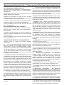
CARBON MONOXIDE DETECTOR REQUIREMENTS
(2)Revise 10.8.3 by adding the following additional
requirements:
(a) For all side wall horizontally vented gas fueled
equipment installed in every dwelling, building or structure
used in whole or in part for residential purposes, including
those owned or operated by the Commonwealth and where
the side wall exhaust vent termination is less than seven
(7) feet above finished grade in the area of the venting,
including but not limited to decks and porches, the following
requirements shall be satisfied:
1. Installation of carbon monoxide detectors. At the time
of installation of the side wall horizontal vented gas fueled
equipment, the installing plumber or gas fitter shall observe
that a hard wired carbon monoxide detector with an alarm
and battery back-up is installed on the floor level where the
gas equipment is to be installed. In addition, the installing
plumber or gas fitter shall observe that a battery operated
or hard wired carbon monoxide detector with an alarm is
installed on each additional level of the dwelling, building or
structure served by the side wall horizontal vented gas fueled
equipment. It shall be the responsibility of the property owner
to secure the services of qualified licensed professionals for
the installation of hard wired carbon monoxide detectors
a. In the event that the side wall horizontally vented
gas fueled equipment is installed in a crawl space or an attic,
the hard wired carbon monoxide detector with alarm and
battery back-up may be installed on the next adjacent floor
level.
58D6002
b. In the event that the requirements of this subdivision
can not be met at the time of completion of installation, the
owner shall have a period of thirty (30) days to comply with
the above requirements; provided, however, that during said
thirty (30) day period, a battery operated carbon monoxide
detector with an alarm shall be installed.
2. Approved Carbon Monoxide Detectors. Each carbon
monoxide detector as required in accordance with the above
provisions shall comply with NFPA 720 and be ANSI/UL 2034
listed and IAS certified.
3. Signage. A metal or plastic identification plate shall be
permanently mounted to the exterior of the building at a
minimum height of eight (8) feet above grade directly in line
with the exhaust vent terminal for the horizontally vented
gas fueled heating appliance or equipment. The sign shall
read, in print size no less than one-half (1/2) inch in size,
“GAS VENT DIRECTLY BELOW. KEEP CLEAR OF ALL
OBSTRUCTIONS.”
4. Inspection. The state or local gas inspector of the side wall
horizontally vented gas fueled equipment shall not approve
the installation unless, upon inspection, the inspector
observes carbon monoxide detectors and signage installed
in accordance with the provisions of 248 CMR 5.08(2)(a)1
through 4.
(b) Exemptions: The following equipment is exempt from
248 CMR 5.08(2)(a)1 through 4:
1. The equipment listed in Chapter 10 entitled "Equipment
Not Required To Be Vented" in the most current edition of
NFPA 54 as adopted by the Board; and
2. Product Approved side wall horizontally vented gas fueled
equipment installed in a room or structure separate from the
dwelling, building or structure used in whole or in part for
residential purposes.
(c) Manufacturer requirements — Gas Equipment
Venting System Provided. When the manufacturer
of Product Approved side wall horizontally vented gas
equipment provides a venting system design or venting
system components with the equipment, the instructions
provided by the manufacturer for installation of the equipment
and the venting system shall include:
1. Detailed instructions for the installation of the venting
system design or the venting system components; and
2. A complete parts list for the venting system design or
venting system.
(d) Manufacturer requirements — Gas Equipment
Venting System Not Provided. When the manufacturer of
a Product Approved side wall horizontally vented gas fueled
equipment does not provide the parts for venting the flue
gases, but identifies “special venting systems,” the following
requirements shall be satisfied by the manufacturer:
1. The referenced "special venting system" instructions shall
be included with the appliance or equipment installation
instructions; and
2. The “special venting systems” shall be Product Approved
31
by the Board, and the instructions for that system shall
include a parts list and detailed installation instructions.
LIMITED LIFETIME WARRANTY
MHS warrants its products to be free of defects in material and workmanship and backs each product with a
Limited Lifetime Warranty. This warranty is to the original purchaser of a MHS product and is not transferable.
Lifetime Warranty
Covered under this warranty are the stove body, combustion chamber, door frame, gold plating (manufacturing
defects only), glass (thermal breakage only), heat exchange system, and burner. This coverage includes parts
and reasonable labor during the first five years of ownership and parts only thereafter.
Five Year Warranty
Ceramic fiber logs, firebrick panels and secondary air tubes are covered for a period of five years from the date
of purchase.
Two Year Warranty
Gas valves, pilot assemblies, thermopiles, thermocouples, regulators, electrical components, cast iron grates and
blowers are covered for a period of two years from the date of purchase.
Exclusions
Items that are not covered under this warranty include but are not limited to damage or chipping to any component
surfaces, gasketing, refractory material, or trim. It does not cover installation or operational problems related to
venting systems, inadequate draft, inadequate gas pressure, adjustments to the appliance, the cost of inspection,
components which have been altered or modified, labor costs, removal and re-installation costs, shipping to or
from the factory or authorized service center, shipping damage, damage from improper use or neglect, installation
damage, damage from unauthorized service, incidental or consequential damage or negative pressure caused
by mechanical systems such as furnaces, fans, clothes dryers etc.
Terms
This warranty shall be void if the appliance is not installed a by qualified installer in accordance with the installation
instructions provided with the appliance and state and local codes. The warranty shall also be void if the appliance is not operated and maintained in accordance with the operating instructions supplied with the appliance.
All service work must be performed by an authorized service representative. Any part or parts, which we deem
defective, will be repaired or replaced at MHS’s option, through an authorized dealer or service provider.
This warranty is expressly in lieu of other warranties, express or implied, including the warranty of merchantability
of fitness for purpose and of all other obligations or liabilities. MHS does not assume for it any other obligations
or liability in connection with the sale or use of the appliance. In states that do not allow limitations on how long
an implied warranty lasts, or do not allow exclusion of indirect damages, those limitations of exclusions may not
apply to you. You may also have additional rights not covered in this Limited Warranty.
MHS reserves the right to investigate any and all claims against the Limited Warranty and decide upon the method
of settlement.
MHS • 149 Cleveland Drive • Paris, KY • 40361
March 2007
P/N 58D6002 • Rev. 5