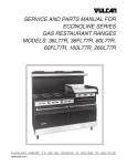
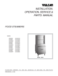
1
SERVICE & PARTS MANUAL FOR
ELECTRIC COUNTERTOP
CONVECTION STEAMER
MODEL VSX9000
VULCAN-HART COMPANY, P.O. BOX 696, LOUISVILLE, KY 40201- 0696, TEL. (502) 778-2791
FORM 30847 (1-94)
THIS
PAGE
INTENTIONALLY
LEFT
BLANK
TABLE OF CONTENTS
GENERAL . . . . . . . . . . . . . . . . . . . . . . . . . . . . . . . . . . . . . . . . . . . . . . . . . . . . . . . . . . . . . . . . . . . . . . . . . . . . . . 4
WATER QUALITY . . . . . . . . . . . . . . . . . . . . . . . . . . . . . . . . . . . . . . . . . . . . . . . . . . . . . . . . . . . . . . . . . . . 4
TROUBLESHOOTING . . . . . . . . . . . . . . . . . . . . . . . . . . . . . . . . . . . . . . . . . . . . . . . . . . . . . . . . . . . . . . . . . . . . . 5
SERVICE . . . . . . . . . . . . . . . . . . . . . . . . . . . . . . . . . . . . . . . . . . . . . . . . . . . . . . . . . . . . . . . . . . . . . . . . . . . . . . . 6
ADJUSTMENT FOR HIGH ALTITUDE LOCATIONS . . . . . . . . . . . . . . . . . . . . . . . . . . . . . . . . . . . . . . . 6
TEST PROCEDURES . . . . . . . . . . . . . . . . . . . . . . . . . . . . . . . . . . . . . . . . . . . . . . . . . . . . . . . . . . . . . . . . 6
WATER FLOWS INTO DRAIN DURING SHUTDOWN . . . . . . . . . . . . . . . . . . . . . . . . . . . . . . . . . . . . . . 7
WATER OVERFLOWS INTO COOKING COMPARTMENT . . . . . . . . . . . . . . . . . . . . . . . . . . . . . . . . . . 7
HEATER ELEMENTS DO NOT COME ON . . . . . . . . . . . . . . . . . . . . . . . . . . . . . . . . . . . . . . . . . . . . . . . 8
COOKING CYCLE DOES NOT OPERATE . . . . . . . . . . . . . . . . . . . . . . . . . . . . . . . . . . . . . . . . . . . . . . . 8
REPLACEMENT PARTS LIST . . . . . . . . . . . . . . . . . . . . . . . . . . . . . . . . . . . . . . . . . . . . . . . . . . . . . . . . . . . . . . 9
WIRING DIAGRAM . . . . . . . . . . . . . . . . . . . . . . . . . . . . . . . . . . . . . . . . . . . . . . . . . . . . . . . . . . . . . . . . . . . . . . 12
-3-
Service and Parts Manual
MODEL VSX9000 ELECTRIC COUNTERTOP
CONVECTION STEAMER
PLEASE KEEP THIS MANUAL
GENERAL
Your Vulcan Steamer is a one-compartment pressureless steam cooker that has been factory assembled and
tested to provide for easy installation. It has been factory set when on to maintain water temperature during the
ready phase at approximately 205°F (just below water boiling point).
Vulcan steamers are produced with quality workmanship and material. Proper installation, usage and
maintenance of your steamer will result in many years of satisfactory performance.
The manufacturer suggests that you thoroughly read this entire manual and carefully follow all of the instructions
provided.
WATER QUALITY
The fact that a water supply is potable is no guarantee that it is suitable for steam generation. Your water supply
must be within these general guidelines:
TOTAL DISSOLVED SOLIDS . . . . . . . . .
TOTAL ALKALINITY . . . . . . . . . . . . . . . . .
SILICA . . . . . . . . . . . . . . . . . . . . . . . . . . . .
CHLORIDE . . . . . . . . . . . . . . . . . . . . . . . .
pH FACTOR . . . . . . . . . . . . . . . . . . . . . . .
Less
Less
Less
Less
7-8
than
than
than
than
60
20
13
30
PPM
PPM
PPM
PPM
Other factors affecting steam generation are iron content, amount of chloridation and dissolved gases. Water
supplies vary from state to state and from locations within a state. Therefore, it is necessary that the local water
treatment specialist be consulted before the installation of any steam generating equipment.
Untreated water contains scale producing minerals which can precipitate onto the surfaces in the boiler. Due
to the temperatures in the boiler, the minerals can bake onto the surfaces and components. This can result in
early component failure and reduced product life.
Mineral scale on components causes several problems:
1. The surfaces of the heating devices become coated with scale, reducing the heat transfer efficiency. This
can produce hot spots on the heating elements and result in premature failure.
2. The water level probes become coated with scale. Scale will bridge across the probe insulator from the metal
extension which senses the water level in the boiler shell. Once this scale becomes wet, the water level
control is unable to maintain the proper water level in the boiler. This situation may cause an electric heating
element to fail as a result of the element not being adequately covered by water.
Strainers and filters will NOT remove minerals from the water.
-4-
TROUBLESHOOTING
PROBLEM
POSSIBLE CAUSES
Cold water flowing continuously into
drain during shutdown.
Either or both solenoid valves are not closing when the steamer
is OFF. Contact your Vulcan-Hart authorized servicer or VulcanHart Company, Louisville, KY (phone number is listed on the
front of this manual).
Water overflowing into cooking
compartment.
Problem with operating probe caused by either:
1. Short between probe terminal and body of steamer. Contact
your Vulcan-Hart authorized servicer or Vulcan-Hart Company,
Louisville, KY (phone number is listed on the front of this
manual).
2. Excessive scale build-up on probe. Contact your VulcanHart authorized servicer or Vulcan-Hart Company, Louisville,
KY (phone number is listed on the front of this manual). Have
water quality analyzed and corrected immediately to avoid
damage to steamer.
Heater elements do not come on.
Problem with contactors or thermostat coated with scalant. Contact
your Vulcan-Hart authorized servicer or Vulcan-Hart Company,
Louisville, KY (phone number is listed on the front of this manual).
Have water quality analyzed and corrected immediately to avoid
damage to steamer.
-5-
SERVICE
WARNING: THE STEAMER AND ITS PARTS ARE HOT. USE CARE WHEN OPERATING, CLEANING OR
SERVICING THE STEAMER. THE COOKING COMPARTMENT CONTAINS LIVE STEAM. STAY CLEAR
WHEN OPENING DOOR.
ADJUSTMENT FOR HIGH ALTITUDE LOCATIONS
Your steamer has been factory set so that when it is ON and during the READY phase, it will maintain water
temperature in the steam generator tank at approxiamtely 205°F (just below water boiling point). However, for
high altitude locations, an authorized Vulcan-Hart servicer must adjust the steamer to achieve this temperature.
To adjust:
1. Remove side panel and turn control panel power switch to ON.
2. Open compartment door, and after about 15 minutes, steam will be seen entering the cooking compartment.
3. Turn thermostat shaft counterclockwise to lower temperature until steam just ceases to enter cooking
compartment and READY light goes on.
4. Replace side panel.
5. Follow TESTING PROCEDURES below.
TESTING PROCEDURES
WARNING: THE STEAMER AND ITS PARTS ARE HOT. USE CARE WHEN OPERATING, CLEANING OR
SERVICING THE STEAMER. THE COOKING COMPARTMENT CONTAINS LIVE STEAM. STAY CLEAR
WHILE OPENING THE DOOR.
Once the steamer is installed and all mechanical connections have been made, thoroughly test the steamer
before operation.
1. Check that proper water, drain, and electrical connections have been made.
2. Turn main power switch ON. After approximately 15 minutes, the READY light should come on, indicating
that the water temperature is 205°F.
3. When READY light comes on, set timer to "5-minute" position. With door open, observe that no steam is
entering compartment.
4. Close compartment door.
compartment.
The READY light will turn off and steam should be heard entering the
-6-
5. Check drain line to ensure that water from the cold water condenser is flowing through the drain line.
6. Open compartment door and observe that steam supply to the chamber is cut off (READY light should again
come on).
7. Close compartment door and let cooking cycle finish. When timer returns to "0-minute" position, a buzzer
will sound signalling the end of the cooking cycle. The buzzer must be turned off manually by setting timer
to its OFF position.
8. To shut the cooker down, turn main power switch OFF and leave the compartment door slightly open.
WATER FLOWS INTO DRAIN DURING SHUTDOWN
When steamer is shut down and cold water is running continuously into the open drain, either or both solenoid
valves did not close when steamer was turned off.
1. Disassemble solenoid valve(s) and examine for scalant or foreign particles lodged in diaphragm or core tube.
2. Clean valve(s) thoroughly and reassemble, or replace valve(s).
WATER OVERFLOWS INTO COOKING COMPARTMENT
When steamer is first turned on for the day, and the following conditions occur:
•
•
•
READY light does not come on after about 15 minutes,
Water begins to overflow into cooking compartment,
Water fill solenoid valve is open,
then any or all of these symptoms may indicate a problem with the operating probe due to either:
1. A short between the operating probe terminal and body of the steamer. Call your Vulcan-Hart authorized
servicer.
2. Excessive scale build-up on the operating probe. This acts as an "insulation" and prevents the probe from
sensing the water level. It is therefore unable to close the water fill (solenoid) valve to shut off the water.
As a temporary solution, with power OFF, unscrew probes, check visually, and clean or chip off sealant.
Replace probes.
This problem is an indication of severe harmful water conditions. Correct immediately to avoid damage to
the steamer. (See WATER QUALITY in this manual.)
-7-
HEATER ELEMENTS DO NOT COME ON
When the steamer is turned ON and heater elements do not activate, and therefore, the READY light does not
come on, then the contactors may be burned out. If a considerable amount of "chattering" of contactors has been
experienced previously, then the thermostat bulb must be coated with scalant and unable to accurately sense
water temperature in the boiler, and therefore, unable to control the contactors.
1. Replace contactors.
2. Unscrew thermostat bulb, clean off scalants, and screw thermostat bulb back in.
This problem is an indication of inadequate water quality and is not covered under warranty. Have water quality
analyzed and corrected immediately to avoid complete malfunction of the steamer.
COOKING CYCLE DOES NOT OPERATE
Observe that the READY light is on. When the door is opened, the door switch will place the set cooking time
on hold and shut down the heater elements. If cooking, steam generating and set time fail to resume when the
door is closed, then check for a problem with the switch.
1. Close the door. Both the main power switch and READY light should be ON.
2. Set timer. READY light will go off and cooking should begin.
-8-
REPLACEMENT PARTS LIST
REPLACEMENT PARTS ORDERING
Parts may be ordered only from your authorized parts and service depot.
The following information must accompany a replacement parts order or it cannot be filled.
A. Model and style or serial number.
B. Voltage, amperage and motor phase.
C. Appliance finish, permafinish, stainless steel, etc. (if applicable to part to be replaced).
Use rating plate located inside cabinet door panel to help you obtain the information listed above. This plate will
provide all the necessary information required by the service agency.
If you need assistance in locating your nearest authorized parts and service depot, contact Vulcan-Hart Product
Service Department at the telephone number shown on the front cover of this manual.
ALL SERVICE PERSONNEL
WHEN SERVICING THIS EQUIPMENT, USE ONLY
CONTROLS ORIGINALLY SUPPLIED ON THIS EQUIPMENT BY
VULCAN-HART COMPANY.
DO NOT SUBSTITUTE.
SUBSTITUTION OF CONTROLS AS STATED ABOVE
WILL AUTOMATICALLY VOID THIS WARRANTY
AND THE CERTIFICATION ASSOCIATED WITH THIS EQUIPMENT.
-9-
VSX9000 STEAMER
- 10 -
REPLACEMENT PARTS
ITEM NO.
1
2
3
4
5
6
7
8
9
12
13
14
15
16
17
18
19
20
21
22
23
24
25
26
27
28
29
30
31
32
33
34
35
36
37
PART NO.
DESCRIPTION
QTY.
844191
844192
844193
844194
840496
840479
844195
844196
842049
844197
840499
844198
844199
881973
844200
843814
843812
843813
844201
844156
844157
843818
836997
843806
843781-3
843807
844202
844260
843803
843802
843804
836926
840511
843969
881978
836927
836928
836929
844261
843940
844262
843941
844204
Door Assembly . . . . . . . . . . . . . . . . . . . . . . . . . . . . . . . . . . . . . . . . . . . . . . .
Door Panel . . . . . . . . . . . . . . . . . . . . . . . . . . . . . . . . . . . . . . . . . . . . . . . . . .
Door Handle . . . . . . . . . . . . . . . . . . . . . . . . . . . . . . . . . . . . . . . . . . . . . . . . .
Latch Assembly . . . . . . . . . . . . . . . . . . . . . . . . . . . . . . . . . . . . . . . . . . . . . .
Striker . . . . . . . . . . . . . . . . . . . . . . . . . . . . . . . . . . . . . . . . . . . . . . . . . . . . . .
Door Bushing . . . . . . . . . . . . . . . . . . . . . . . . . . . . . . . . . . . . . . . . . . . . . . . .
Gasket Plate . . . . . . . . . . . . . . . . . . . . . . . . . . . . . . . . . . . . . . . . . . . . . . . . .
Door Gasket . . . . . . . . . . . . . . . . . . . . . . . . . . . . . . . . . . . . . . . . . . . . . . . . .
Door Switch . . . . . . . . . . . . . . . . . . . . . . . . . . . . . . . . . . . . . . . . . . . . . . . . .
Door Actuator (NS) . . . . . . . . . . . . . . . . . . . . . . . . . . . . . . . . . . . . . . . . . . .
Rack Slide (NS) . . . . . . . . . . . . . . . . . . . . . . . . . . . . . . . . . . . . . . . . . . . . . .
Tank Assembly . . . . . . . . . . . . . . . . . . . . . . . . . . . . . . . . . . . . . . . . . . . . . . .
Component Mounting Plate . . . . . . . . . . . . . . . . . . . . . . . . . . . . . . . . . . . . .
Thermostat . . . . . . . . . . . . . . . . . . . . . . . . . . . . . . . . . . . . . . . . . . . . . . . . . .
High Limit Thermostat . . . . . . . . . . . . . . . . . . . . . . . . . . . . . . . . . . . . . . . . .
Buzzer . . . . . . . . . . . . . . . . . . . . . . . . . . . . . . . . . . . . . . . . . . . . . . . . . . . . . .
Relay . . . . . . . . . . . . . . . . . . . . . . . . . . . . . . . . . . . . . . . . . . . . . . . . . . . . . . .
Relay . . . . . . . . . . . . . . . . . . . . . . . . . . . . . . . . . . . . . . . . . . . . . . . . . . . . . . .
"O" Ring . . . . . . . . . . . . . . . . . . . . . . . . . . . . . . . . . . . . . . . . . . . . . . . . . . . .
Probe 21⁄2" . . . . . . . . . . . . . . . . . . . . . . . . . . . . . . . . . . . . . . . . . . . . . . . . . . .
Probe 31⁄2" . . . . . . . . . . . . . . . . . . . . . . . . . . . . . . . . . . . . . . . . . . . . . . . . . . .
Level Control . . . . . . . . . . . . . . . . . . . . . . . . . . . . . . . . . . . . . . . . . . . . . . . .
Contactor . . . . . . . . . . . . . . . . . . . . . . . . . . . . . . . . . . . . . . . . . . . . . . . . . . .
Timer . . . . . . . . . . . . . . . . . . . . . . . . . . . . . . . . . . . . . . . . . . . . . . . . . . . . . . .
Dial . . . . . . . . . . . . . . . . . . . . . . . . . . . . . . . . . . . . . . . . . . . . . . . . . . . . . . . .
Pilot Light . . . . . . . . . . . . . . . . . . . . . . . . . . . . . . . . . . . . . . . . . . . . . . . . . . .
Power Switch . . . . . . . . . . . . . . . . . . . . . . . . . . . . . . . . . . . . . . . . . . . . . . . .
Control Panel . . . . . . . . . . . . . . . . . . . . . . . . . . . . . . . . . . . . . . . . . . . . . . . .
Solenoid Valve . . . . . . . . . . . . . . . . . . . . . . . . . . . . . . . . . . . . . . . . . . . . . . .
Solenoid Valve . . . . . . . . . . . . . . . . . . . . . . . . . . . . . . . . . . . . . . . . . . . . . . .
Blow Down Solenoid . . . . . . . . . . . . . . . . . . . . . . . . . . . . . . . . . . . . . . . . . .
Element Gasket . . . . . . . . . . . . . . . . . . . . . . . . . . . . . . . . . . . . . . . . . . . . . .
Terminal Block . . . . . . . . . . . . . . . . . . . . . . . . . . . . . . . . . . . . . . . . . . . . . . .
End Section . . . . . . . . . . . . . . . . . . . . . . . . . . . . . . . . . . . . . . . . . . . . . . . . .
Transformer . . . . . . . . . . . . . . . . . . . . . . . . . . . . . . . . . . . . . . . . . . . . . . . . .
Element Assembly 208V 7.5KW (Select as Required) . . . . . . . . . . . . . . .
Element Assembly 240V 7.5KW (Select as Required) . . . . . . . . . . . . . . .
Element Assembly 480V 7.5KW (Select as Required) . . . . . . . . . . . . . . .
Trough . . . . . . . . . . . . . . . . . . . . . . . . . . . . . . . . . . . . . . . . . . . . . . . . . . . . .
"Y" Strainer (NS) . . . . . . . . . . . . . . . . . . . . . . . . . . . . . . . . . . . . . . . . . . . . .
Compression Elbow (NS) . . . . . . . . . . . . . . . . . . . . . . . . . . . . . . . . . . . . . .
Connector (NS) . . . . . . . . . . . . . . . . . . . . . . . . . . . . . . . . . . . . . . . . . . . . . .
Leveler (NS) . . . . . . . . . . . . . . . . . . . . . . . . . . . . . . . . . . . . . . . . . . . . . . . . .
(NS) Not Shown
- 11 -
1
1
1
1
1
1
1
1
1
1
2
1
1
1
1
1
1
1
1
1
1
1
1
4
1
1
1
1
1
1
1
1
4
1
1
1
1
1
1
1
1
1
4
WIRING DIAGRAM
FORM 30847 (1-94)
- 12 -
PRINTED IN U.S.A.