1
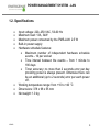
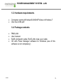
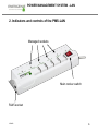
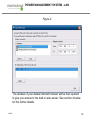
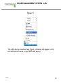
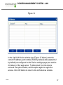
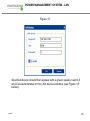
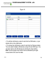
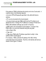
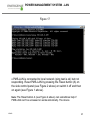
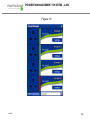
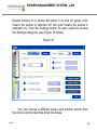
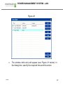
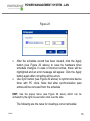
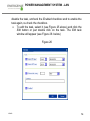
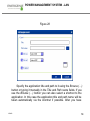
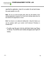
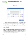
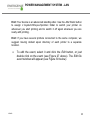
POWER MANAGEMENT SYSTEM - LAN PMS-LAN User Manual 1. Introduction Congratulations on your purchase of the Power Management System LAN & Surge Protector. Your PMS-LAN is an advanced surge protector with power management features. Four sockets are individually manageable by the computer via the LAN interface. The sockets can be switched on/off by a timer schedule, by direct user control or by programmable events. It is also possible to pre-program the unit event timer schedule (hardware schedule) and then disconnect the PMS-LAN from the managing computer. The device can be used as an advanced standby-killer. You can manage your PMS-LAN via the Internet from all over the world, even from your Smartphone. 1.1. Features 120430 The main rocker switch switches all sockets on and off Each manageable socket can be switched on and off via the software control window 2 All brands and logos are registered trademarks of their respective owners POWER MANAGEMENT SYSTEM - LAN 120430 The unit can be pre-programmed with a timed schedule. The schedule will operate even when the managing computer is switched off or disconnected. A typical application could be: “switch my peripherals on every working day at 8:50 AM”. The manageable sockets can also be controlled from the attached computer Power Manager software to react to a particular event (e.g. Windows or other programs startup/shutdown), simple typical applications could be: “switch my scanner on when I want to scan” or “switch my printer off whenever I exit Windows” Real time Voltage monitor provides information about the actual status of each manageable socket (on or off). This information can be further utilized in various ways (e.g. to check the proper execution of the switching commands) The unit can be assigned a network name as a shared LAN resource and can be afterwards accessed and managed from anywhere within the local area network or Internet (provided the managing computer is switched on) Surge Protection. Includes resettable circuit breaker. 3 All brands and logos are registered trademarks of their respective owners POWER MANAGEMENT SYSTEM - LAN 1.2. Specifications 120430 Input voltage: 220–250 VAC, 50-60 Hz Maximum load: 13A, 3kW Maximum power consumed by the PMS-LAN: 2.5 W Built-in power supply Hardware schedule features: Maximum number of independent hardware schedule events – 16 per socket Time interval between the events – from 1 minute to 180 days Timer accuracy: no more than 2 seconds error per day providing power is always present. Otherwise there can be an additional (up to 2 seconds) error per each power off. Working temperature range: from +10 to +40 °C Dimensions: 378 x 98 x 55 mm Net weight: 1.0 kg 4 All brands and logos are registered trademarks of their respective owners POWER MANAGEMENT SYSTEM - LAN 1.3. Hardware requirements Computer running Windows® 2000/XP/Vista or Windows 7 One free USB port 1.4. Package contents 120430 PMS-LAN User manual RJ45 LAN patch cable, RJ45 LAN cross over cable CD with Power Manager software for Windows (use of this software is not compulsory) 5 All brands and logos are registered trademarks of their respective owners POWER MANAGEMENT SYSTEM - LAN 2. Indicators and controls of the PMS-LAN Managed sockets Main rocker switch RJ45 socket 120430 6 All brands and logos are registered trademarks of their respective owners POWER MANAGEMENT SYSTEM - LAN 2.1. Side panels Figure 2 120430 7 All brands and logos are registered trademarks of their respective owners POWER MANAGEMENT SYSTEM - LAN 2.2. Indicators 120430 Main rocker switch Z (Figure 1 above) is illuminated - the PMS-LAN is connected to the power supply and active. Power indicator (Figure 1 above) is illuminated. The nonmanageable sockets (marked with the sign ) are switched on. The indicator Socket 1 (2,3,4) (Figure 1 above) is lit. The particular socket is switched on. The indicator Schedule/LAN activity (Figure 2 above) blinks green – there is some LAN activity taking place. The indicator Schedule/LAN activity (Figure 2 above) blinks red as the reset procedure is being executed. The indicator Schedule/LAN activity (Figure 2 above) stays red if an active hardware schedule for any socket exists. 8 All brands and logos are registered trademarks of their respective owners POWER MANAGEMENT SYSTEM - LAN 2.3. Controls Main rocker switch (Z) enables power to be supplied to the sockets. The two unmanaged sockets will be powered. Circuit breaker. Pressing this button will reset the circuit breaker protective device if it has been tripped. Reset button (A). The PMS-LAN can be restarted if it can’t be accessed or works abnormally. All the IP settings and device settings will remain the same as before, but the server time will become outdated and all schedules will be reset. Master switch button (B). Switches all the manageable sockets on and off regardless of their current status or schedule that is being executed. IP config button (C). Resets the PMS-LAN to the default IP settings. 120430 9 All brands and logos are registered trademarks of their respective owners POWER MANAGEMENT SYSTEM - LAN 3. Installation The device is for internal use only. It is strongly recommended to avoid damp or wet places for installation. The PMS-LAN should be connected to a standard UK mains socket. 3.1. Getting started Connect PMS-LAN to the wall socket first and then to the LAN socket (or your computer LAN card) with the provided patch cord or vice-versa. The PMS-LAN can now be switched on and off by means of the Main rocker switch (Z). The first and the last sockets of the PMS-LAN are marked with the symbol . These two sockets are switched on and off by means of the Main rocker switch (Z) and cannot be managed by the computer – so they are termed non-manageable sockets in this manual. When the PMS-LAN is switched on, the red POWER indicator illuminates. In this case both non-manageable sockets are now live and connected to the power supply. 120430 10 All brands and logos are registered trademarks of their respective owners POWER MANAGEMENT SYSTEM - LAN 120430 The sockets: Socket 1, Socket 2, Socket 3 and Socket 4 can be managed or pre-programmed by computer via the LAN connection. They are called manageable sockets in this manual. The manageable sockets of the PMS-LAN can be programmed to be on or off. The current status of each manageable socket is represented by the corresponding indicator which will be lit if socket has power to it. If the Main rocker switch (Z) (Figure 1 above) is turned off then the manageable sockets cannot be switched on by either the Power manager software or the hardware schedule. When the Main rocker switch (Z) is switched on, the Power Manager software or the hardware schedule will also be enabled. The manageable sockets can then be switched on and off. Master switch button (B) (see Figure #2 above) can also switch all the manageable sockets on and off regardless of their current status or schedule that is being executed. To switch them on you should keep the button pressed for 1-2 seconds. To switch them off you should keep the button pressed for more than 3 seconds. To protect the connected devices from possible high current and short circuit, the PMS-LAN is equipped with an automatic circuit breaker. 11 All brands and logos are registered trademarks of their respective owners POWER MANAGEMENT SYSTEM - LAN Note: If the total power consumption (or peak power) of the devices, connected to the PMS-LAN exceeds 3 kWatts, the circuit breaker will automatically disconnect the PMS-LAN from the mains supply. Remove the excessive load and then press the Circuit breaker button to restore the power supply (Figure 2 above). To be able to use PMS-LAN you will now have to complete its LAN configuration. 3.2. Obtaining an IP address. Option A – via connection to the LAN (recommended) Make sure the PMS-LAN is connected to the local network with the RJ-45 patch cable. Note: by default the factory setting of PMS-LAN is DHCP enabled. If your LAN has a router with built-in DHCP server (which is very common) then PMS-LAN will automatically get an IP address from the DHCP server. Proceed to section 3.3 below in this case. Option B – via connection to the managing computer 120430 12 All brands and logos are registered trademarks of their respective owners POWER MANAGEMENT SYSTEM - LAN If your LAN does not have DHCP server you may prefer to connect PMS-LAN directly to the managing computer LAN adapter (network card) using the supplied crossover RJ-45 cable. If you choose for option B then the following procedure is required to let the PMS-LAN obtain a fixed IP address: Turn PMS-LAN off (with the Main rocker switch Z) Hold down the IP Config (C) button on the side control panel (see Figure 2 above) with the tip of a pen and turn the Main rocker switch Z on. Wait for about 3 seconds until you hear the sockets switching twice. This procedure will force the PMS-LAN to reset itself to the default settings below ... IP: 192.168.0.254 Subnet mask: 255.255.255.0 Gateway: 192.168.0.1 DNS:0.0.0.0 DHCP: enabled IP filtering: disabled Power Manager client port: 5000 120430 13 All brands and logos are registered trademarks of their respective owners POWER MANAGEMENT SYSTEM - LAN ... PMS-LAN then searches for an IP address from your eventual DHCP server. If no DHCP server is found within 1 minute, PMS-LAN will then automatically revert to the default settings (see above, with IP address 192.168.0.254). 3.3. Power Manager installation It is now time to identify which IP address has been obtained. We need to carry out the following: Insert the Power Manager CD into a PC CD-ROM drive. This PC can be connected either to the same LAN where the device is (if you chose option A) or directly to the device with the crossover RJ-45 cable (if you chose option B). If for any reason the automatic setup does not work, then open CD-ROM drive in the My Computer window and launch SETUP.EXE from the CD Follow the instructions to install the software Note: Antivirus or firewall software may block connection to the PMSLAN. Please, configure antivirus/firewall to permit connection to the IP address and port of your PMS-LAN. 120430 14 All brands and logos are registered trademarks of their respective owners POWER MANAGEMENT SYSTEM - LAN 3.4. IP configuration The utility Find PMS-LAN (see Figure 4 below) will run automatically during the software installation but it can also be started from Start/All Programs/Power Manager. The IP range where you would like to search for PMS-LAN will be set automatically according to the IP settings of your LAN adapter but can be changed manually in the Adapter subnet fields. Now press the Search button. Note: only PMS-LAN within a local subnet can be found. If your computer LAN adapter is not in the (default) subnet of PMS-LAN (as may be the case if you chose option B section 3.2) you will have to change its IP address manually to be able to find PMSLAN. For example if you wish to find PMS-LAN (with the default IP 192.168.0.254), the IP address of your computer should be set as 192.168.0.XXX (where XXX stands for any digit, for example 1) and the subnet mask should be 255.255.255.0. After the searching the IP addresses of the found PMS-LAN devices will appear in the list box. Select PMS-LAN which you want to access, and press the Open button (see Figure 4 below). 120430 15 All brands and logos are registered trademarks of their respective owners POWER MANAGEMENT SYSTEM - LAN Figure 4 The window of your default internet browser will be then opened to give you access to the built-in web-server. See section 4 below for the further details. 120430 16 All brands and logos are registered trademarks of their respective owners POWER MANAGEMENT SYSTEM - LAN 4. The web server The PMS-LAN is equipped with a web-server which allows it to be managed using a web browser such as Internet Explorer, Firefox etc. 4.1. Web-server login page To access the web server of PMS-LAN, just open Internet Explorer (or other browser) and input the IP address of PMS-LAN (for example http://192.168.1.241). If you have used Find PMSLAN utility to locate PMS-LAN then you will be taken to this webpage automatically. Login page will then be displayed (see Figure #5 below). Note: Java script must be enabled in your Internet Explorer (or another browser) settings. Otherwise, you get an error message: WARNING! JAVASCRIPT IS DISABLED! Figure 5 120430 17 All brands and logos are registered trademarks of their respective owners POWER MANAGEMENT SYSTEM - LAN The default password is 1. It is recommended to change the password on the Device settings page (see section 4.6 below) after the first login. After a successful login you will face the Socket 1 Status page (see section 4.2 below). Note: You may then need to open the LAN settings page (see section 4.5 below) to complete the IP configuration. 4.2. EnerGenie page With the help of EnerGenie page (see Figure 6 below) you will be able to see the status of all your four manageable sockets, and to switch the sockets on and off manually. The status of your sockets, as well as the buttons to switch them on/off are located at the top of the page. Note: the names of the sockets can be changed from the default Socket1/Socket2/Socket3/Socket4 to something meaningful on the page Socket Name Settings (see section 4.4 below). The EnerGenie page also allows you to setup access and management (switch on and off) of your PMS-LAN from anywhere via Internet even if it does not have an external IP address. To setup this free service you should follow two simple steps: 120430 18 All brands and logos are registered trademarks of their respective owners POWER MANAGEMENT SYSTEM - LAN 1. Register the device. To restrict access to the device via the Internet to the rightful owner only, the device should be registered – e.g. assigned to your account. To register the device, simply push the button Register on this page (see Figure #6 below). You will then be redirected to Login page of EnerGenie.com. If you already own an account at EnerGenie.com then just enter your login and password on this page and you are done. Otherwise, use the Registration button on the Login page to create a new account. After your successful login (regardless whether you created a new or used an existing account) your PMS-LAN is automatically registered. 2. Return back to the EnerGenie page of your PMS-LAN (see Figure 6 below). Push Activate button to let the device initiate communication with EnerGenie.com server. The EnerGenie page will then start updating itself until the Status becomes Registered Activated Connected (see Figure 6 below). 120430 19 All brands and logos are registered trademarks of their respective owners POWER MANAGEMENT SYSTEM - LAN Figure 6 120430 20 All brands and logos are registered trademarks of their respective owners POWER MANAGEMENT SYSTEM - LAN After a successful registration and activation, the button Register will be renamed to Login (and will then open the Login page EnerGenie.com) and the button Activate will become Deactivate. If you decide to stop managing your PMS-LAN via the Internet, use the Deactivate button to stop communication with the EnerGenie.com server. You can change the registration of your PMS-LAN and assign it to another account via the EnerGenie.com website (see section 5 below). See section 5 below for further details on managing your PMSLAN via the EnerGenie.com website. 4.3. Socket page Each of the 4 manageable sockets ot the PMS-LAN has a separate status page headed with the socket number and name. (see Figure 7 below). Each page shows socket status and the scheduled events for this socket. It also allows the socket to be switched on or off manually. (see section 4.4 below). 120430 21 All brands and logos are registered trademarks of their respective owners POWER MANAGEMENT SYSTEM - LAN Figure 7 120430 22 All brands and logos are registered trademarks of their respective owners POWER MANAGEMENT SYSTEM - LAN The socket shown in Figure #7 is currently off. It will turn on automatically on the 14th of January at 10:15 and switch off at 18:00. The two events will be executed with a loop period of 1 day. The current time of the web-server and information about the last successful timer synchronization is also displayed. Automatic timer synchronization is used if the Use NTP for time correction option is enabled (see section 4.6 below). Note: If a socket has a switching fault: e.g. it has been switched on but the whole device is switched off OR e.g. it has been switched off but there is voltage at the socket ...then the warning message Wrong voltage on socket! will be shown above the Event schedule (see Figure #7 above). This message may also indicate that this socket is defective. For setting up the socket schedule use the Set schedule button (see Figure 8). 120430 23 All brands and logos are registered trademarks of their respective owners POWER MANAGEMENT SYSTEM - LAN Figure 8 120430 24 All brands and logos are registered trademarks of their respective owners POWER MANAGEMENT SYSTEM - LAN Choose the date and time of the scheduled event. If you wish the events to be executed periodically then check the Loop option and set the loop period. To commit your changes, press the Apply button. To delete the entered schedule, press the Clear schedule button. Note: The hardware schedule keeps running even when the device is powered off. However it is recommended not to power off the device for extended periods as the built-in battery has a limited lifespan. If the battery dies, the schedule will be completely cleared. The total lifetime of the battery is no less than 2 years if the device is powered off, and no less than 5 years if the device is powered on. 4.4. Socket Name settings page On the Socket name settings page (see Figure 9 below) you can assign suitable names to the sockets. These names will be shown on the EnerGenie page and on the Socket pages. Note: The maximum socket name length is 11 characters. Hint: Identify your socket with the equipment which is plugged in. 120430 25 All brands and logos are registered trademarks of their respective owners POWER MANAGEMENT SYSTEM - LAN Figure 9 120430 26 All brands and logos are registered trademarks of their respective owners POWER MANAGEMENT SYSTEM - LAN 4.5. LAN settings page Figure 10 120430 27 All brands and logos are registered trademarks of their respective owners POWER MANAGEMENT SYSTEM - LAN On the LAN settings page (see Figure 10 above) you can set up DHCP, IP address, Subnet mask, Gateway, DNS server and IP filter (up to 3 IP addresses can then be enabled for remote access). The new settings will be applied immediately after you press the Apply button. IP address, Subnet mask, Gateway, DNS server will be used only if the DHCP option is disabled. If you set DHCP option it is recommended for your own convenience to set up your DHCP server so that it always provides the same IP address to PMS-LAN. To do that you will need to know the MAC address of PMS-LAN. It can be found on this page or on the bottom sticker of the device. The MAC address is fixed and cannot be changed. DNS server address is important to be properly set up in case you wish to enable the NTP timer correction option (see section 4.6 below). IP filter option is needed to prevent unauthorized access to the server. It restricts the web server access from any computer with IP address different from IP1, IP2 and IP3. Make sure that you input IP1, IP2, and IP3 correctly before enabling this option. 120430 28 All brands and logos are registered trademarks of their respective owners POWER MANAGEMENT SYSTEM - LAN Power Manager client port is used for connecting with the Power Manager software, normally it is not needed to change this setting. 4.6. Device settings page On the device settings page you can setup name, password and internal time of the PMS-LAN (Figure 11 below). 120430 29 All brands and logos are registered trademarks of their respective owners POWER MANAGEMENT SYSTEM - LAN Figure 11 120430 30 All brands and logos are registered trademarks of their respective owners POWER MANAGEMENT SYSTEM - LAN 1. Initialise the internal clock by entering the current local date and time. Alternatively if the option Use NTP for timer correction is enabled (by default) then the time will be taken from the NTP server. The device will try to connect with the server every 18 hours. The first synchronization would take place in 15 seconds after you press the Apply button. NTP server field should have a valid name of NTP server (by default “pool.ntp.org”). If for any reason the NTP time correction doesn’t work you can choose the best NTP server for your country via the website www.pool.ntp.org. Note: for NTP time correction to work properly the device should have access to the Internet and have a proper DNS server setting (see section 4.5 above). 2. Server name can be convenient to identify the web server if you have more than one PMS-LAN. It is “Server 1” by default. 3. The password is necessary to access PMS-LAN both from your web browser and the Power Manager software (see section 6 below). This password is case-sensitive and can be up to 32 characters long. Alphanumeric characters and spaces may be entered. Only the first eight characters of the password are used to access the device with the Power 120430 31 All brands and logos are registered trademarks of their respective owners POWER MANAGEMENT SYSTEM - LAN Manager software. You will need to enter this password in the Add LAN device window (see section 7 below). The Power Manager software accesses PMS-LAN via a particular client port (by default 5000). You can change this port to any other except port 80 which is always occupied by the web server. Use the Apply button to save your settings. 4.7. Web-server logout You will be logged out automatically after 10 minutes of inactivity. While you are logged in to the web server, it can’t be accessed from any other computer. If another user tries to access the web server which is running an active session the error message will be shown on the login page: Somebody with another IP has already logged in. Try again later. In the meantime the Power Manager software (see section 6) can still access the PMS-LAN. 5. EnerGenie.com device interface With your free personal account at EnerGenie.com website you will be able to access your PMS-LAN from anywhere in the world using any Internet-enabled device (desktop PC, laptop, smartphone etc). See section 4.2 above on how to register your PMS-LAN on the server and setup the connection. 120430 32 All brands and logos are registered trademarks of their respective owners POWER MANAGEMENT SYSTEM - LAN 5.1. Logging in To login into your EnerGenie account just open the webpage www.energenie.com/user in your Internet browser and enter your login and password in the login window (see Figure 12 below). Figure 12 120430 33 All brands and logos are registered trademarks of their respective owners POWER MANAGEMENT SYSTEM - LAN This page will automatically update itself and will keep showing you the time when your device was last seen online (the latest time when the device communicated with the server) and the status of each socket. Click your user name to change your account settings. Click the device to change its name and/or transfer it to another account. Click the sockets to change their names Click the On/Off buttons to switch the sockets on or off. Note: the switching command can only be properly executed if the device is switched on, connected to the Internet and activated. Note: the Last seen online status information lets you check if the device keeps communicating with the server. 120430 34 All brands and logos are registered trademarks of their respective owners POWER MANAGEMENT SYSTEM - LAN 6. POWER MANAGER SOFTWARE INSTALLATION This is available on the Power Manager CD supplied with the unit. 6.1. Finding the PMS-LAN Install Power Manager software v.4.0.0.0 (or higher) on a PC connected to your local network. After a successful installation a socket icon system tray. will appear in your With a right mouse click on the socket icon you will get access to the Power Manager main menu. Choose LAN devices from the menu (see Figure 13 below). 120430 35 All brands and logos are registered trademarks of their respective owners POWER MANAGEMENT SYSTEM - LAN Figure 13 The LAN devices window (see Figure 14 below) will appear, click the Add button to add a new PMS-LAN device. 120430 36 All brands and logos are registered trademarks of their respective owners POWER MANAGEMENT SYSTEM - LAN Figure 14 In the Add LAN device window (see Figure 15 below) enter the correct IP address, port number (5000 by default) and password (1 by default) as configured on the Device settings page (see section 4.6 above) of the web server. To disconnect from the device uncheck the option Enable, set this option again to regain the access. Click OK button to return to the LAN devices window. 120430 37 All brands and logos are registered trademarks of their respective owners POWER MANAGEMENT SYSTEM - LAN Figure 15 Specified device should then appear with a green square next to it and Connected status in the LAN devices window (see Figure 16 below). 120430 38 All brands and logos are registered trademarks of their respective owners POWER MANAGEMENT SYSTEM - LAN Figure 16 To edit the LAN device, select it and click the Edit button, or just double click on the LAN device To remove the LAN device, select it and click the Remove button. You can select multiple LAN devices using Ctrl and Shift keys. You can also remove all LAN devices by clicking the Clear button Hint: Use the popup menu which can be activated by the right mouse button click over the table. 120430 39 All brands and logos are registered trademarks of their respective owners POWER MANAGEMENT SYSTEM - LAN If the status of PMS-LAN shows the device not to be Connected - it could be due to the following reasons: Incorrect IP/Port/Password specified in the Add LAN device window PC is not connected to the local network You are trying to access PMS-LAN from the PC which is not allowed to do so. Change PC IP address or change IP filter list in PMS-LAN hardware settings (see section 4.5 above) PMS-LAN is not connected to local network. To check if the PMS-LAN is on your local network using the ping test: Go to Start->Run Type cmd Type ping <PMS-LAN IP Address specified in utility> in the window which would appear For instance, PMS–LAN with IP address 192.168.2.189 is connected to the local network. Then the cmd window will look as shown in the Figure 17 below: 120430 40 All brands and logos are registered trademarks of their respective owners POWER MANAGEMENT SYSTEM - LAN Figure 17 PMS-LAN is connected to local network (ping test is ok) but not responding. Reset PMS-LAN by pressing the Reset button (A) on the side control panel (see Figure 2 above) or switch it off and then on again (see Figure 1 above). Note: The Reset button A (see Figure 2 above) can sometimes help if PMS-LAN can’t be accessed or works abnormally. The device 120430 41 All brands and logos are registered trademarks of their respective owners POWER MANAGEMENT SYSTEM - LAN will then be restarted. All the IP settings and device settings will remain the same as before, but the server time will be reset and all schedules will become outdated. 6.2. Managing the PMS-LAN After successful connection, close LAN devices window. You can now start managing PMS-LAN via the Power Manager interface. Double click on the socket icon in the system tray or select Open from the popup menu (see Figure 13 above). You will get the window of the main control panel shown on the Figure 18below. 120430 42 All brands and logos are registered trademarks of their respective owners POWER MANAGEMENT SYSTEM - LAN Figure 18 120430 43 All brands and logos are registered trademarks of their respective owners POWER MANAGEMENT SYSTEM - LAN Double clicking on a socket will switch it on and off (green color means the socket is switched off; red color means the socket is switched on). Click the Settings button for each socket to access the Settings dialog box (see Figure 19 below). Figure 19 You can choose a different device and another socket from the Device and Socket drop down list-boxes. 120430 44 All brands and logos are registered trademarks of their respective owners POWER MANAGEMENT SYSTEM - LAN 120430 It is possible name a device and socket (for example Printer or Scanner) using the Rename button Check the System tray checkbox if you want to put the icon of the socket into the system tray. You can choose the icon from drop down list box. The icon is a simple way to switch the device connected to the socket on/off or check the device status You can also assign a hot key to switch the socket on/off. Check the Switch ON and Switch OFF checkboxes and specify the hot keys To switch the socket on/off on Windows startup (wake up), check the On Windows startup checkbox and choose the required action To switch the socket on/off on the Windows shutdown (sleep), check the On Windows shutdown checkbox and choose the required action 45 All brands and logos are registered trademarks of their respective owners POWER MANAGEMENT SYSTEM - LAN 7. Power Manager Core Features 7.1 Setting up the hardware schedule Using the Hardware schedule button available from the Settings window you can create the hardware timer schedule (see Figure 20 below). To add a new record, click the Add button. 120430 46 All brands and logos are registered trademarks of their respective owners POWER MANAGEMENT SYSTEM - LAN Figure 20 120430 The window Add entry will appear (see Figure 21 below). In the dialog box, specify the required time and the action 47 All brands and logos are registered trademarks of their respective owners POWER MANAGEMENT SYSTEM - LAN Figure 21 120430 To edit the record, select it and click the Edit button or just double click on the entry. The window Edit entry will appear (see Figure 22 below) 48 All brands and logos are registered trademarks of their respective owners POWER MANAGEMENT SYSTEM - LAN Figure 22 120430 To remove the record, select it and click the Remove button (see Figure 20 above). You can select multiple entries using Ctrl and Shift keys. You can also remove all entries from the schedule by clicking the Clear button (see Figure 20 above) To repeat your event (for example if you want to perform the same events every day) use the Loop button (see Figure 20 above) and specify the loop time period in the Edit loop period window (see Figure 23 below) 49 All brands and logos are registered trademarks of their respective owners POWER MANAGEMENT SYSTEM - LAN Figure 23 After the schedule record has been created, click the Apply button (see Figure 20 above) to save the hardware timer schedule changes. In case of incorrect entries, these will be highlighted and an error message will appear. Click the Apply button again after correcting all the errors Use Sync button (see Figure 20 above) to synchronize device timer with PC clock. Note that after synchronization past entries will be removed from the schedule HINT: Use the popup menu (see Figure 20 above) which can be activated by the right mouse button click over the table. The following are the rules for creating a correct schedule: 120430 50 All brands and logos are registered trademarks of their respective owners POWER MANAGEMENT SYSTEM - LAN The new event time should be in the future There can not be a duplicate entry The total quantity of events can not exceed 16 per socket The total quantity of events also depends on the total execution period of the schedule The interval between the present and the last entry can not exceed 180 days Without loop the total execution period of the schedule can not exceed 215 days Loop period cannot exceed 180 days NOTE: If the device is powered off, the hardware schedule is still in the device memory and will be resumed when the power supply is restored. However the whole schedule will be then delayed by the duration of the power cut off. The PMS-LAN will start beeping indicating a hardware schedule problem. Press the “Silence” button once to turn the beeper off if you wish to ignore the delay in the schedule. Pressing the “Silence” button again after the beeps have been silenced will cause the schedule to be adjusted by one minute. Alternatively create and upload a new schedule using the ‘Timer schedule’ dialog box. 120430 51 All brands and logos are registered trademarks of their respective owners POWER MANAGEMENT SYSTEM - LAN 7.2 Setting up the software schedule Use the Software schedule button available on the Settings window to create a software timer schedule (see Figure 24 below). Note: the software timer schedule will only be executed if the managing computer is on and the Power Manager is launched. Figure 24 120430 52 All brands and logos are registered trademarks of their respective owners POWER MANAGEMENT SYSTEM - LAN To add a new task, click the Add button. The Add task window will appear (see Figure 25 below) Figure 25 In the Add task window, check Switch ON time and/or Switch OFF time checkboxes and specify the time to switch the socked on and/or off. If you want the same event to be performed periodically, check Perform task every checkbox and specify the time interval. You can also add remarks about the task in the Comment field. To 120430 53 All brands and logos are registered trademarks of their respective owners POWER MANAGEMENT SYSTEM - LAN disable the task, uncheck the Enabled checkbox and to enable the task again, re-check the checkbox. To edit the task, select it (see Figure 25 above) and click the Edit button or just double click on the task. The Edit task window will appear (see Figure 26 below) Figure 26 120430 54 All brands and logos are registered trademarks of their respective owners POWER MANAGEMENT SYSTEM - LAN To remove the task, select it and click the Remove button (see Figure 20 above). You may select multiple tasks using Ctrl and Shift keys. You can also remove all tasks by clicking the Clear button Hint: Use the popup menu which can be activated by the right mouse button click over the table (see Figure 25 above). 7.3 Setting up application events Using the Application events window you can specify the socket events when a certain application is launched or closed down. You can also associate switching the sockets off or on with placement and removal of particular files in certain folders. To use this feature push Application events button available from the Settings window (see section 6.1 above – Figure 19). You will get the following window (see Figure 27 below). 120430 55 All brands and logos are registered trademarks of their respective owners POWER MANAGEMENT SYSTEM - LAN 120430 56 All brands and logos are registered trademarks of their respective owners POWER MANAGEMENT SYSTEM - LAN Figure 27 120430 To add a new program event, click the Add app button. The Add program event dialog will appear (see Figure 28 below) 57 All brands and logos are registered trademarks of their respective owners POWER MANAGEMENT SYSTEM - LAN Figure 28 Specify the application title and path to it using the Browse (…) button or typing it manually in the Title and Path name fields. If you use the Browse (…) button you can also select a shortcut to the application. In this case the application title and path name will be taken automatically via the shortcut if possible. After you have 120430 58 All brands and logos are registered trademarks of their respective owners POWER MANAGEMENT SYSTEM - LAN specified the application, check On run and/or On exit and choose the event (switch on or off). Note: The On run event will take place when the first window of the selected application is opened. The On exit event will take place when the last window of the application is closed. Hint: Your device is an advanced standby-killer. Using this feature you can for example switch your scanner on/off whenever Photoshop is started/closed. To add a new file event, click the Add folder button (see Figure 27 above). The Add file event window will appear (see Figure 29 below). 120430 59 All brands and logos are registered trademarks of their respective owners POWER MANAGEMENT SYSTEM - LAN Figure 29 Specify the path to the folder you would like to monitor using the Browse (…) button or typing it manually in the Path name field. Specify the File name mask using wildcard characters: *, ?. Check then On placing and/or On removal checkboxes and select the event and delay. Note: The On placing event will take place when the first file matching the specified file name mask is placed into the specified folder. The On removal event will take place when the last file matching the specified file name mask is removed from the specified folder. 120430 60 All brands and logos are registered trademarks of their respective owners POWER MANAGEMENT SYSTEM - LAN Hint: Your device is an advanced standby-killer. Use the Add folder button to assign c:\\system32\\spool\\printers folder to switch your printer on whenever you start printing and to switch it off again whenever you are ready with printing. Hint: If you have several printers connected to the same computer, we suggest moving default spool directory of each printer to a separate location. 120430 To edit the event, select it and click the Edit button, or just double click on the event (see Figure 27 above). The Edit file event window will appear (see Figure 30 below) 61 All brands and logos are registered trademarks of their respective owners POWER MANAGEMENT SYSTEM - LAN Figure 30 To remove the event, select it and click the Remove button (see Figure 27 above). You can select multiple events using Ctrl and Shift keys. You can also remove all events by clicking the Clear button HINT: Use the popup menu which can be activated by the right mouse button click over the table. 120430 62 All brands and logos are registered trademarks of their respective owners POWER MANAGEMENT SYSTEM - LAN 8. Power Manager advanced features The following information is for advanced users which wish to have full access to the advanced features of the PMS-LAN. Click the Advanced features button available from the Settings window (see section 6.1 above). The following window will then appear (see Figure 31 below). Figure 31 120430 63 All brands and logos are registered trademarks of their respective owners POWER MANAGEMENT SYSTEM - LAN 8.1. Processing the alarms Whenever the actual measured voltage on the manageable socket deviates from the status set by your switching tasks, it is called a Voltage alarm. The Voltage alarm can for example be caused by a blackout and will be resolved after power returns. The Voltage alarm can also be triggered if for any reason a switching task could not be carried out (switching malfunction). The default action by an alarm is to record this event into a log file and show a popup Alarm log window (see Figure 32 below). Figure 32 You might wish to process this situation in a different way, e.g. send an email message somewhere etc. 120430 64 All brands and logos are registered trademarks of their respective owners POWER MANAGEMENT SYSTEM - LAN Check the Disable alarm log window checkbox to disable popup Alarm log window (applies to all devices) Check the When alarm goes on checkbox, then click Browse(…) button to select the desired program to launched whenever a voltage alarm is triggered Check the When alarm goes off checkbox, then click Browse(…) button to select the desired program to launched after the alarm status (see above) is resolved the the be the be 8.2. Setting up network devices To avoid other users having to access the PMS-LAN via the IP address, it can be declared as a shared device on the server. . To make the PMS-LAN shared on your computer press the button Device sharing... in the Advanced features window (see Figure 31 above). The window Device sharing will appear (see Figure 33 below) 120430 65 All brands and logos are registered trademarks of their respective owners POWER MANAGEMENT SYSTEM - LAN Figure 33 Set the checkbox Share this device via network if you want to enable the network access to the device (via this PC). To prevent unauthorized access to the device enter the access password in the field Password. Note: Port 6100 should be open. Contact your LAN administrator for further details. To be able to use this shared PMS-LAN on a client PC choose Shared devices from the Main menu (see Figure 13 above). You will get the following window (see Figure 34 below). 120430 66 All brands and logos are registered trademarks of their respective owners POWER MANAGEMENT SYSTEM - LAN Figure 34 To add a new remote device, press the Add button. You will see the window Add network device (see Figure 35 below). 120430 67 All brands and logos are registered trademarks of their respective owners POWER MANAGEMENT SYSTEM - LAN Figure 35 Enter the network name of the server which is connected to the PMS-LAN in the field Hostname. Enter the name of the target PMS-LAN in the field Device name. Enter access password in the field Password. To disconnect from the device uncheck the option Enable, set this option on again to regain the access. To locate the shared device in your local network, click the button Find. A dialog 120430 68 All brands and logos are registered trademarks of their respective owners POWER MANAGEMENT SYSTEM - LAN box Find network device will appear. Choose the proper server and then the device and click OK button. To edit the network device, select it and click the Edit button, or just double click on the network device (see Figure 34 above). The Edit network device window will appear (see Figure 36 below). Figure 36 120430 69 All brands and logos are registered trademarks of their respective owners POWER MANAGEMENT SYSTEM - LAN To remove the network device, select it and click the Remove button (see Figure 20 above). You can select multiple network devices using Ctrl and Shift keys. You can also remove all network devices by clicking the Clear button HINT: Use the popup menu which is available with the right mouse button click over the table. 8.3. Managing the PMS-LAN via your own software To let you switch the sockets from your own applications the following command line interface syntax is supported: pm.exe -[on | off] -device name -socket name Examples: 120430 "C:\Program Files\Energenie\Power Manager\pm.exe" -on -My EnerGenie -Socket1 "E:\Utils\PM3\pm.exe" Table lamp -off -My EnerGenie - 70 All brands and logos are registered trademarks of their respective owners POWER MANAGEMENT SYSTEM - LAN Execute pm.exe with -info key (pm.exe –info) to get the complete information about the status of the current devices. For each of the connected devices the following information will then be provided and placed into Info.ini file in the Power Manager folder: DeviceName - the user specified device name Socket#name, where # is replaced by a certain socket number - the user specified socket name Socket#SwitchState, where # is replaced by a certain socket number - TRUE, when the socket is switched on, FALSE, when the socket is switched off Socket#VoltageState, where # is replaced by a certain socket number - TRUE, when voltage presence on the socket is detected, FALSE, when there is no voltage on the socket; Example: NOTE: Each use of this command line option totally overrides the data in Info.ini file. NOTE: Power Manager should be active. 120430 71 All brands and logos are registered trademarks of their respective owners POWER MANAGEMENT SYSTEM - LAN 9. Troubleshooting Problem The circuit breaker is activated (tripped). The switching command is not carried out, the rocker switch and indicators are not lit. The status of PMS-LAN in Power Manager does not become Connected PMS-LAN is connected to local network (ping test is ok) but not responding. Connection to PMS-LAN is lost. It seems something is wrong with its IP address. 120430 Solution The load connected to the device is too high, some of the devices connected to the PMS-LAN should be disconnected and the circuit breaker should be reset. There is no power supply to the PMSLAN. Please, make sure the PMS-LAN is connected to the power supply and the rocker switch is switched on. Try to ping the device (see section 6.1 above) Reset PMS-LAN by pressing the Reset button on the side control panel (see Figure 2 above) or switch it off and then on again using the Main rocker switch Z (see Figure 1 above). Make sure PMS-LAN is connected to LAN and switched on. Launch Find PMS-LAN utility. You can also try to 72 All brands and logos are registered trademarks of their respective owners POWER MANAGEMENT SYSTEM - LAN use the IP config (C) button to let the device renew its IP address (see section 3.2 above) Frequently Asked Questions Q: What appliances can I use this extension lead for? Answer: As it is 13A rated, it can be used with any household device. Q: Can the PMS-LAN unit be used outside? Answer: No, this product is for indoor use only. Q: Can each socket be programmed individually? Answer: Yes, there are four sockets that are controlled separately. The other two sockets are uncontrolled and always powered when the power switch is ON. Q. Does the unit have to be connected to the computer at all times? 120430 73 All brands and logos are registered trademarks of their respective owners POWER MANAGEMENT SYSTEM - LAN A: No the unit has internal hardware timers for each controlled socket that allows it to operate disconnected from the computer once it has been programmed. Q. I am having trouble connecting to my device via the internet. It just says Activated. Trying to connect in the browser. A: A problem with your DNS ip address settings could also be causing this. The DNS settings are set on the web interface page of the device. Please check the DNS address has a valid value – not 0.0.0.0. You can check this against your router. Typically you can log into your router via you browser using address 192.168.0.1 which is common. You need to know the router login id and password e.g. admin and ???? Most likely the DNS server address from your router will have been automatically inserted with your internet service provider’s DNS server address. Q. I can operate it ok over my own local network and via the power manager software. However, when I try connecting over the internet it doesn’t connect. After I log in, it brings up a message that it is executing a command and nothing further happens. A: There might be a conflict/problem with your router settings. Make sure that the router permits the transmission 120430 74 All brands and logos are registered trademarks of their respective owners POWER MANAGEMENT SYSTEM - LAN of UDP pockets from device to the outside via port 1025 ( Typical NAT configuration allows this). Please check the DNS server has been set up as in the previous question. www.energenie4u.co.uk Energenie is a trading name of Sandal plc, Claremont House, Deans Court, Bicester, Oxon, OX26 6BW ©2012 120430 75 All brands and logos are registered trademarks of their respective owners POWER MANAGEMENT SYSTEM - LAN 120430 76 All brands and logos are registered trademarks of their respective owners