1
UX-310DE
FO-730DE/NX-530DE
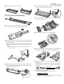
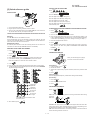
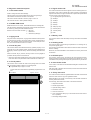
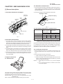
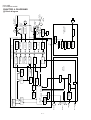
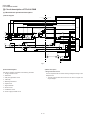
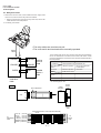
Separation rubber
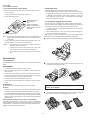
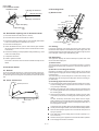
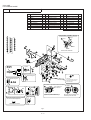
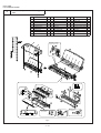
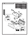
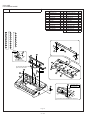
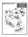
5. Recording block
Last page of document
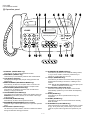
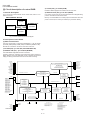
(1) General view
,,,,,,,,,,
,,,,,,,,,,
,,,,,,,,,,
,,,,,,,,,,
,,,,,,,,,,
,,,,,,,,,,
,,,,,,,,,,
,,,,,,,,,,
,,,,,,,,,,
Back of document
RP release plate
First page of document
Platen roller
PO roller
PU roller
Pinch roller
Paper feed spring
Paper feed roller
Rotation
plate
PO gude
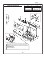
Fig. 4
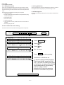
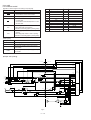
Film cartridge
RP
hopper
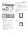
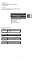
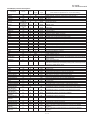
3-5. Documents requiring use of document carrier
1) Documents smaller than B6 (128mm x 182mm).
2) Documents thinner than the thickness of 0.06mm.
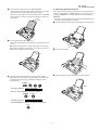
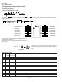
Supply
side
Take-up
side
3) Documents containing creases, folds, or curls, especially those whose
surface is curled (maximum allowable curl is 5mm).
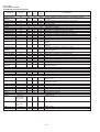
Thermal Haad
4) Documents containing tears.
Film sensor
lever
Imaging film
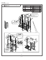
Fig. 6
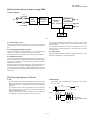
5-1. Driving
5) Carbon-backed documents. (Insert a white sheet of paper between
the carbon back and the document carrier to avoid transfer of carbon
to the carrier.)
In the drive mechanism, the rotating force of the pulse motor for both
transmission and reception is transmitted to the paper supply roller, the
recording paper feed roller and imaging film drive gear through the pulse
motor axle gear, reduction gear and planetary gear.
6) Documents containing an easily separable writing material (e.g., those
written with a lead pencil).
7) Transparent documents.
5-2. Recording
8) Folded or glued documents.
This equipment employs the thermal transcription system which used
the thermal head imaging film.
Document in document carrier should be inserted manually into the
feeder.
1) Thermal head
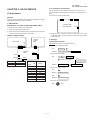
4. Document release
The thermal head is composed of 2,016 heating elements in traverse
line, and the resolution power is 8 dots/mm. The maximum speed is 10
ms/line.
4-1. General
2) Structure of recording mechanism
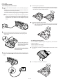
To correct a jammed document or to clean the document running surface, pull the insertion side of document center of the operation panel.
To open the upper document guide, the operation panel must be opened
first.
Recording is achieved by applying a suitable pressure to the thermal
head through the imaging film of the recording paper feed roller and the
recording paper.
The main scanning is electronically done, and the sub-scanning is me
chanically done (by sending the recording paper with the recording paper feed roller).
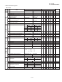
4-2. Cross section view
3) Recording paper transfer sequence
Operation panel unit
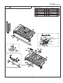
a) The recording paper stored in the RP hopper is fed with the PU roller,
and the recording paper is stopped when the P-IN sensor is turned
on by sensing its lead edge.
b) Hereafter, the imaging film and recording paper are transferred with
the recording paper feed roller, and thermal transcription is done on
the recording paper.
c) After thermal transcription, the imaging film is taken up by the roller
on the take-up side, and the recording paper is discharged by the PO
roller.
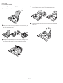
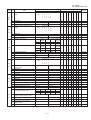
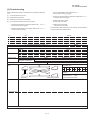
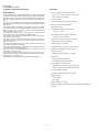
As basic, the density unevenness mainly results from the longitudinal misalignment of the thermal head to the heater line. Otherwise,
the head is in uneven contact with the recording paper feed roller, or
the imaging film is wrinkled.
Lower cabinet
Fig. 5
1 Are the power and signal cables of the thermal head suitably treated?
2 Does the same symptom appear even if the thermal head pres-sure
The following items are described as the simplified checking method.
spring is replaced?
3 Is the feed roller of the recording paper concentric? (Density is uneven at intervals.)
4 Does the same symptom appear even if the thermal head is replaced?
5 Is the imaging film stained or wrinkled?
3–2