1
HP ProLiant ML110 Server
Operations and Maintenance Guide
June 2004 (Third Edition)
Part Number 347748-003
Regulatory Model Number HSTNS-3100
© 2004 Hewlett-Packard Development Company, L.P.
Intel, Pentium, and Celeron are US registered trademarks of Intel Corporation.
Microsoft, Windows, and Windows NT are US registered trademarks of Microsoft Corporation.
Torx is a trademark of Camcar-Textron Screw & Mfg. Co.
Hewlett-Packard Company shall not be liable for technical or editorial errors or omissions contained herein. The
information in this document is provided “as is” without warranty of any kind and is subject to change without
notice. The warranties for HP products are set forth in the express limited warranty statements accompanying such
products. Nothing herein should be construed as constituting an additional warranty.
HP ProLiant ML110 Server Operations and Maintenance Guide
June 2004 (Third Edition)
Part Number 347748-003
Regulatory Model Number HSTNS-3100
Contents
About This Guide
Audience Assumptions............................................................................................................................... vii
Technician Notes........................................................................................................................................ vii
Where to Go for Additional Help.............................................................................................................. viii
Telephone Numbers ............................................................................................................................ viii
Chapter 1
System Features
Features Summary ..................................................................................................................................... 1-1
Hardware............................................................................................................................................. 1-1
Software .............................................................................................................................................. 1-2
System Specifications................................................................................................................................ 1-3
Physical Specifications ....................................................................................................................... 1-3
Environmental Specifications ............................................................................................................. 1-3
Power Supply Requirements............................................................................................................... 1-3
Chapter 2
System Structure
External Structure...................................................................................................................................... 2-1
Front Panel with Bezel........................................................................................................................ 2-1
Rear Panel ........................................................................................................................................... 2-3
Internal Structure....................................................................................................................................... 2-4
Internal Components........................................................................................................................... 2-4
Mainboard Components...................................................................................................................... 2-5
Chapter 3
System Setup
Setup Reminders........................................................................................................................................ 3-1
Checking the Contents ........................................................................................................................ 3-1
Selecting a Site.................................................................................................................................... 3-1
System Setup ............................................................................................................................................. 3-2
Connecting Peripherals ....................................................................................................................... 3-2
Powering On/Off the Server ............................................................................................................... 3-6
HP ProLiant ML110 Server Operations and Maintenance Guide
iii
Contents
Chapter 4
System Configuration
Hardware Configuration ............................................................................................................................4-1
Pre- and Post-installation Procedures..................................................................................................4-1
System Covers.....................................................................................................................................4-2
Hardware Configuration Procedures ...................................................................................................4-6
Server Configuration................................................................................................................................4-28
Chapter 5
BIOS Setup Utility
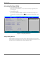
Setup Utility Overview ..............................................................................................................................5-1
Accessing the Setup Utility........................................................................................................................5-2
Setup Utility Menus ...................................................................................................................................5-2
To Move Around the Setup Screen .....................................................................................................5-3
Recording BIOS Settings...........................................................................................................................5-4
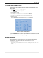
System Summary Screen ...........................................................................................................................5-4
To View the System Summary Screen ................................................................................................5-5
System Passwords......................................................................................................................................5-5
To Set a System Password...................................................................................................................5-6
To Change a System Password............................................................................................................5-6
To Remove a System Password ..........................................................................................................5-7
To Reset a System Password...............................................................................................................5-7
Closing the Setup Utility............................................................................................................................5-8
BIOS Update and Recovery.......................................................................................................................5-8
To Create the BIOS Update/Recovery Diskette ..................................................................................5-8
To Update BIOS..................................................................................................................................5-9
To Reset the BIOS Settings.................................................................................................................5-9
To Perform BIOS Recovery ................................................................................................................5-9
Clearing CMOS .......................................................................................................................................5-10
Setting Hardware Protection ....................................................................................................................5-11
Chapter 6
System Maintenance
Preventive Maintenance Procedures ..........................................................................................................6-1
Troubleshooting Procedures ......................................................................................................................6-2
Troubleshooting Tools ........................................................................................................................6-2
Troubleshooting Procedures................................................................................................................6-3
Determining the Cause of a Problem Condition..................................................................................6-4
Specific Troubleshooting Procedures..................................................................................................6-5
Chapter 7
System Diagnostics
System Diagnostics Overview ...................................................................................................................7-1
Power-On Self-Test (POST) ......................................................................................................................7-1
POST Error Indicators.........................................................................................................................7-1
POST-related Troubleshooting............................................................................................................7-9
Hardware Diagnostic Software ................................................................................................................7-10
Diagnostics for Windows ..................................................................................................................7-11
iv
HP ProLiant ML110 Server Operations and Maintenance Guide
Contents
Chapter 8
Addendum - SATA Configuration
SATA Overview........................................................................................................................................ 8-1
SATA Hot-Plug Cage Cabling .................................................................................................................. 8-1
SATA Drive Installation ........................................................................................................................... 8-2
Creating the FastTrak S150 SX4 RAID Controller Driver Diskette ......................................................... 8-5
SATA LED Indicator Status...................................................................................................................... 8-6
Appendix A
Regulatory Compliance Notices
Regulatory Compliance Series Number ................................................................................................... A-1
Federal Communications Commission Notice ......................................................................................... A-1
Class B Equipment............................................................................................................................. A-1
Declaration of Conformity for Products Marked with the FCC Logo, United States Only.............. A-2
Modifications ..................................................................................................................................... A-2
Cables................................................................................................................................................. A-2
Canadian Notice (Avis Canadien) ............................................................................................................ A-3
Class B Equipment............................................................................................................................. A-3
European Union Notice ............................................................................................................................ A-3
Japanese Notice ........................................................................................................................................ A-3
BSMI ........................................................................................................................................................ A-4
Korean MIC.............................................................................................................................................. A-4
Device Notices ......................................................................................................................................... A-4
Laser Device Notices ......................................................................................................................... A-4
Mouse Compliance Statement ........................................................................................................... A-5
Battery Replacement Notice..................................................................................................................... A-5
Non-Nuclear Usage .................................................................................................................................. A-6
Appendix B
Electrostatic Discharge
Preventing Electrostatic Damage ..............................................................................................................B-1
Grounding Methods To Prevent Electrostatic Damage .............................................................................B-1
Appendix C
Power Cord Set Requirements
General Requirements ...............................................................................................................................C-1
Country-Specific Requirements ................................................................................................................C-2
Index
HP ProLiant ML110 Server Operations and Maintenance Guide
v
About This Guide
This maintenance and service guide can be used for reference when servicing
HP ProLiant ML110 servers.
WARNING: To reduce the risk of personal injury from electric shock and hazardous
energy levels, only authorized service technicians should attempt to repair this
equipment. Improper repairs can create conditions that are hazardous.
Audience Assumptions
This guide is for service technicians. HP assumes you are qualified in the servicing of
computer equipment and trained in recognizing hazard in products with hazardous energy
levels and are familiar with weight and stability precautions for rack installations.
Technician Notes
WARNING: Only authorized technicians trained by HP should attempt to repair this
equipment. All troubleshooting and repair procedures are detailed to allow only
subassembly/module-level repair. Because of the complexity of the individual boards
and subassemblies, no one should attempt to make repairs at the component level or
to make modifications to any printed wiring board. Improper repairs can create a safety
hazard.
WARNING: To reduce the risk of personal injury from electric shock and hazardous
energy levels, do not exceed the level of repairs specified in these procedures.
Because of the complexity of the individual boards and subassemblies, do not attempt
to make repairs at the component level or to make modifications to any printed wiring
board. Improper repairs can create conditions that are hazardous.
WARNING: To reduce the risk of electric shock or damage to the equipment:
•
Disconnect power from the system by unplugging all power cords from the power
supplies.
•
Do not disable the power cord grounding plug. The grounding plug is an important
safety feature.
•
Plug the power cord into a grounded (earthed) electrical outlet that is easily
accessible at all times.
HP ProLiant ML110 Server Operations and Maintenance Guide
vii
About This Guide
CAUTION: To properly ventilate the system, you must provide at least 7.6 cm (3.0 in.) of
clearance at the front and back of the server.
CAUTION: The server is designed to be electrically grounded (earthed). To ensure proper
operation, plug the AC power cord into a properly grounded AC outlet only.
NOTE: Any indications of component replacement or printed wiring board modifications may void any
warranty.
Where to Go for Additional Help
In addition to this guide, the following information sources are available:
•
User documentation
•
Service training guides
•
Service advisories and bulletins
•
QuickFind information services
Telephone Numbers
For the name of your nearest HP authorized reseller:
•
In the United States, call 1-800-345-1518.
•
In Canada, call 1-800-263-5868.
For HP technical support:
viii
•
In the United States and Canada, call 1-800-652-6672.
•
Outside the United States and Canada, refer to www.hp.com
HP ProLiant ML110 Server Operations and Maintenance Guide
1
System Features
Features Summary
Hardware
•
Single CPU socket that supports 478-pin Intel processors
•
Intel 879P core logic chipset consisting of:
®
— 82879P – north bridge
— ICH-S – south bridge
•
Phoenix BIOS v4.06 chipset
•
SMSC LPC47M192 Super I/O chipset
•
Onboard Broadcom 5705 10/100/1000 Mbps Gigabit Ethernet controller
•
ATI Rage XL chipset with 8 MB SDRAM of video memory
•
Four DIMM slots with support for:
®
®
®
®
™
— DDR 400 unbuffered ECC DIMMs in 256 MB, 512 MB, or 1 GB configuration
— Up to 2 DIMMs per-channel, single-sided and/or double-sided
— Byte masking on writes through data masking
— Single-bit Error Correcting Code (or Error Checking and Correcting) on the system
memory interface
•
Five PCI bus slots with two separate bus channels
— Two 32-bit/33 MHz 5V PCI bus slots
— Three 64-bit/66 MHz 3.3V PCI-X bus slots
•
Media storage
— 3.5-inch, 1.44 MB floppy disk drive
— IDE CD-ROM drive
HP ProLiant ML110 Server Operations and Maintenance Guide
1-1
System Features
•
Optional media storage capacity
— Full-height common bay supports any paired combination of tape drive, internal
backup device, or DVD-ROM drive
— Hard disk drive cage that supports four non-hot swappable PATA (Parallel Advanced
Technology Attachment) or SCSI drives
or
— Hot-swappable drive cage that supports four SATA (Serial Advanced Technology
Attachment) drives
•
External ports, all located on the rear panel of the server. These ports are color-coded for
easy matching to corresponding I/O device.
— PS/2 keyboard port
— PS/2 mouse port
— USB ports (2)
— Monitor port
— Serial port
— Parallel port
— LAN port
•
Standard autoranging 350-watts power supply unit with PFC function
•
Cooling system includes a system fan (rear panel) and a CPU fan (attached to the heat
sink)
•
NOS (Network Operating System) support includes:
Software
®
®
— Novell NetWare 5.1
— Novell NetWare 6.0
— Novell NetWare 6.5
— Novell Small Business Suite
®
®
— Red Hat Linux 9.0
— Red Hat Enterprise Linux ES 2.1
— Microsoft Windows Server 2003 and Small Business Server 2003
•
Diagnostic tools include:
— BIOS Setup Utility
— Diagnostics for Windows
•
1-2
ACPI (Advanced Configuration and Power Interface)-compliant power management
scheme
HP ProLiant ML110 Server Operations and Maintenance Guide
System Features
System Specifications
Physical Specifications
•
Height – 430 mm (16.93 in.)
•
Width – 200 mm (7.87 in.)
•
Depth – 500 mm (19.69 in.)
•
Weight
— Basic configuration approximately 16.5 kg. (36.24 lbs) – excludes keyboard and
monitor.
— Fully loaded approximately 22 kg. (47.41lbs) – excludes keyboard and monitor.
Environmental Specifications
•
Temperature
— Operating: +10 to +35°C (+50 to +95°F)
— Non-operating: -10 to +60°C (+14 to +140°F)
•
Humidity
— Operating: 20% to 80% RH, non-condensing
— Non-operating: 20% to 90% RH, non-condensing
— Storage: 20% to 90% RH, non-condensing
•
Altitude
— Operating: -16 to 3,048 m (-50 to 10,000 ft)
— Non-operating: -16 to 10,600 m (-50 to 35,000 ft)
•
Thermal output
— Maximum operating: 1907 BTU/hr
•
Acoustic emissions
— Normal configuration: LpA: <35dBA, operating at room temperature
— Maximum configuration: LpA: <70dBA
Power Supply Requirements
•
Input type: AC
•
Input maximum range: 100 to 127 VAC@45/66Hz / 200 to 240 VAC@45/66Hz
•
Maximum current: 115VAC @8.0A
•
Inrush current: 80A@115AVC
•
Operating power: 350W @25°C; 320W @50°C
HP ProLiant ML110 Server Operations and Maintenance Guide
1-3
2
System Structure
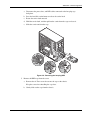
This chapter describes the server’s physical external and internal structure. A view of the
mainboard layout is also provided.
External Structure
Front Panel with Bezel
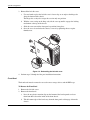
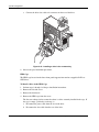
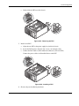
In the illustration below, the server is shown with both the front bezel attached (items labeled
1 through 8), and removed (items labeled 9 through 13).
Figure 2-1: Front panel components
Refer to Table 2-1 on the next page for a list of front panel components.
HP ProLiant ML110 Server Operations and Maintenance Guide
2-1
System Structure
Table 2-1: Front Panel Components
Item
Icon
Description
1
CD-ROM drive
2
CD-ROM drive mechanical eject hole
3
CD-ROM drive eject button
4
CD-ROM drive activity indicator
5
Full-height common bays
6
Power indicator (green)
This LED indicator provides the power state
of the server.
•
Steady green when the server is
operating normally.
•
Blinking green when the server is in
Standby mode.
•
Off when the server is powered off.
7
Power button
8
Drive activity indicator (amber)
This LED indicator shows the power state of
any IDE or SCSI device installed in the server
including CD-ROM drive(s), IDE hard disk
drives, and SCSI devices connected to the
SCSI controller board.
2-2
•
Flickering amber during any IDE or SCSI
device activity.
•
Off when there is no IDE or SCSI device
activity.
9
Floppy disk drive (FDD)
10
FDD activity indicator
11
FDD eject button
12
Torx® screws for the hard disk drive
(HDD) cage
13
HDD cage
HP ProLiant ML110 Server Operations and Maintenance Guide
System Structure
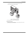
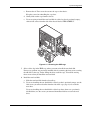
Rear Panel
Figure 2-2: Rear panel components
Table 2-2: Rear Panel Components
Item
Icon
Description
1
PS/2 mouse port (green)
2
PS/2 keyboard port (purple)
3
Serial port (teal)
4
Parallel port (burgundy)
5
Monitor port (blue)
6
USB ports (black)
7
LAN port (RJ-45)
8
PCI slot covers
9
PSU fan
10
Power supply cable socket
11
Thumbscrews for the detachable left-side cover
12
System fan
13
Retention clips for the PCI slot covers
14
Kensington® lock
HP ProLiant ML110 Server Operations and Maintenance Guide
2-3
System Structure
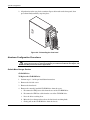
Internal Structure
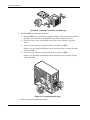
Internal Components
Figure 2-3: Internal components
Table 2-3: Internal Components
Item
2-4
Description
1
Standard autoranging 350-watts PSU
2
System fan
3
Expansion board
4
Mainboard
5
HDD cage
6
Retaining lever for the FDD
7
Retaining levers for 5 ¼” devices
HP ProLiant ML110 Server Operations and Maintenance Guide
System Structure
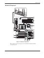
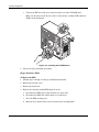
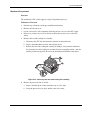
Mainboard Components
Figure 2-4: Mainboard components
Refer to Table 2-4 on the next page for a list of mainboard components and their
corresponding codes.
HP ProLiant ML110 Server Operations and Maintenance Guide
2-5
System Structure
Table 2-4: Mainboard Components
Item
Component Code
Description
1
CN3
Top: PS/2 mouse port
Bottom: PS/2 keyboard port
2
CN4
Top: Parallel port
Left: Serial port
Right: Monitor port
3
CN6
USB ports (two)
4
JK1
LAN port (RJ-45)
5
CN2
4-pin, 12V ATX power connector
6
CN1
20-pin ATX power connector
7
DIMM1 to DIMM4
DIMM slots
8
CPU FAN
3-pin CPU fan connector
9
U7
Intel 82879P chipset (north bridge)
10
U18
Intel ICH-S chipset (south bridge)
11
IDE2
Secondary IDE channel UDMA-100
12
IDE1
Primary IDE channel UDMA-100
13
SATA1
7-pin port 1 for 150-MBps SATA
14
SATA2
7-pin port 0 for 150-MBps SATA
15
FLOPPY
34-pin FDD connector
16
U27
Phoenix BIOS v4.06 chipset
17
CN11
4-pin SCSI activity LED connector
18
BT1
Battery
19
CN14
9-pin front panel I/O connector
20
SW1
Dip switch
21
BU1
Internal buzzer
22
PCI2 to PCI4
64-bit/66 MHz PCI bus slots
23
PCI1 and PCI5
32-bit/33 MHz PCI bus slots
24
U29
Video frame buffer
25
U25
ATI Rage XL VGA chipset
26
U16
Broadcom 5705 LAN chipset
continued
2-6
HP ProLiant ML110 Server Operations and Maintenance Guide
System Structure
Table 2-4: Mainboard Components continued
Item
Component Code
Description
27
U14
SMSC LPC47M192 Super I/O chipset
28
CPU
CPU socket
29
SYSFAN1
3-pin system fan connector (rear)
Note: Listed in the next section are the default settings for the dip switch.
Dip Switch Settings
The table below shows the settings for the dip switch (SW1). The switch status indicated in
bold text is the default setting.
Table 2-5: DIP Switch Settings
Switch
Switch Status
Function
SW1-1
On
Clear CMOS Enabled
Off
Clear CMOS Disabled
On
Boot Block Enabled
Off
Normal Boot
On
Clear Password
Enabled
Off
Clear Password
Disabled
On
No FWH Protection
Off
FWH Protection by
Software Enabled
SW1-5
On
PCI 32 / 33MHz
SW1-6
On
SW1-5
Off
SW1-6
On
SW1-5
On
SW1-6
Off
SW1-2
SW1-3
SW1-4
PCI 64 / 66MHz
PCI-X 64 / 66MHz
Note: Set SW1-5 and SW1-6 to the combinations shown above to select the
operation mode for the PCI2 through PCI4 slots. Both switches, by default,
are set to the Off position, and are dependent on the card installed into each
slot.
HP ProLiant ML110 Server Operations and Maintenance Guide
2-7
3
System Setup
Setup Reminders
Checking the Contents
Inspect the packaging container for evidence of mishandling during transit. If the packaging
container is damaged, photograph it for reference.
Remove the server from the packaging container and, using the list below, check that all parts
and accessories are included.
•
HP ProLiant ML110 server
•
2-button PS/2 mouse
•
HP 104-key PC keyboard
•
HP ProLiant ML110 Server Installation Sheet
•
HP ProLiant ML110 Server Startup CD-ROM
This Startup CD contains on-line HP documentation as well as drivers and utilities for
configuring the server.
If any of the above items are damaged or missing, contact your dealer immediately. Save the
packaging container and packing materials in the event you need to package the server for
reshipment.
Selecting a Site
Before unpacking and installing the system, select a suitable site for the system for maximum
efficiency. Consider the following factors when choosing a site for the system:
•
Near a properly grounded, three-pronged wall power outlet
•
Clean and dust-free
•
Sturdy surface free from vibration
•
Well-ventilated and away from sources of heat, with the ventilation openings on the
server kept free of obstructions
HP ProLiant ML110 Server Operations and Maintenance Guide
3-1
System Setup
•
Secluded from strong electromagnetic fields and noise caused by electrical devices such
as elevators, copy machines, air conditioners, large fans, large electric motors, radio and
TV, transmitters, and high-frequency security devices
•
Access space provided so the server power cords can be unplugged from the power outlet
NOTE: The power button on the system does not turn off system AC power. To remove AC power from
the system, you must unplug the server’s power cord from the power outlet. The power cord is
considered the disconnect device to the main (AC) power.
IMPORTANT: Surge suppressor is recommended. In geographic regions that are susceptible to
electrical storms, it is strongly recommended that you plug the server into a surge suppressor.
Power Supply Specification in Selecting an Installation Site
Generally, the server can handle the normal transient effect caused by an inrush current when
it is first connected to an AC power source. However, if you install several HP servers on one
circuit, precautions are necessary. If there is a power failure and power restored afterwards,
all the servers immediately begin to draw inrush current at the same time. If the circuit
breakers on the incoming power line have insufficient capability, the breaker may trip and
thus prevent the servers from powering up. When selecting a site for server installation, allow
for the additional inrush current. For more information, refer to the “Power Supply
Requirements” section in Chapter 1.
System Setup
The following sections provide instructions on connecting peripherals, as well as power
on/off procedures.
Connecting Peripherals
The server unit, keyboard, mouse, and monitor constitute the basic system. Before
connecting any other peripherals, connect these peripherals first to test if the system is
running properly. The I/O connectors are all located on the rear panel of the server. These
connectors are color-coded for easy matching.
NOTE: If you have a console switch box, refer to the documentation accompanying the switch box for
instructions on connecting the keyboard, mouse, and monitor.
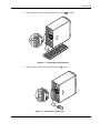
To Connect a Mouse and Keyboard
PS/2 Mouse and Keyboard
CAUTION: The keyboard and mouse ports are both PS/2 ports, but are not interchangeable.
If you plug the keyboard into the mouse port, or the mouse into the keyboard port, you will get
an error message.
3-2
HP ProLiant ML110 Server Operations and Maintenance Guide
System Setup
•
Plug the keyboard cable into the PS/2 keyboard port
(purple).
Figure 3-1: Connecting a PS/2 keyboard
•
Plug the mouse cable into the PS/2 mouse port
(green).
Figure 3-2: Connecting a PS/2 mouse
HP ProLiant ML110 Server Operations and Maintenance Guide
3-3
System Setup
USB Mouse and Keyboard
The server comes with two USB 2.0 ports. If you are going to use a USB mouse and
(black).
keyboard, plug the cables of these I/O peripherals into either USB port
Figure 3-3: Connecting a USB mouse and keyboard
NOTE: Some USB devices have a built-in USB port that allows you to daisy chain other devices.
To Connect a Monitor
3-4
•
If you are going to use a flat-panel monitor, refer to its accompanying documentation for
connection instructions.
•
To connect a VGA monitor, simply plug the monitor cable into the monitor port
(blue).
HP ProLiant ML110 Server Operations and Maintenance Guide
System Setup
Figure 3-4: Connecting a VGA monitor
To Connect a Printer
The server provides support for serial, parallel and USB printers.
•
If you are going to use a serial printer, connect the printer cable into the serial port
(teal).
•
If you are going to use a USB printer, connect the printer cable into either USB port
(black).
•
To connect a parallel printer, plug the printer cable into the parallel port
(burgundy).
Figure 3-5: Connecting a parallel printer
HP ProLiant ML110 Server Operations and Maintenance Guide
3-5
System Setup
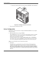
Powering On/Off the Server
To Apply Power to the Server
After making sure that you have set up the server properly and connected all the required
peripheral cables, you can now apply power to the server.
1. Verify that the monitor is properly connected to the server and is plugged into a properly
grounded, wall power outlet.
2. Connect the server’s power cable.
Plug the power cable into the power cable socket located on the rear panel of the server.
Then plug the other end of the power cable into a properly grounded, wall power outlet.
Figure 3-6: Connecting the server’s power cable
3. Press the power button
on the front panel and then turn on the monitor.
Figure 3-7: Turning on the server
3-6
HP ProLiant ML110 Server Operations and Maintenance Guide
System Setup
The system starts up and loads the operating system. A welcome message is displayed. If the
system does not turn on or boot after pressing the power button, refer to the “Power
Problems” section in Chapter 6 for troubleshooting instructions.
After the welcome message display, a series of POST (Power–On Self–Test) messages
appears. The POST messages indicate if the system is running well or not. If an error
condition occurs, note any error messages appearing on the display. Go to the “POST Error
Indicators” section in Chapter 7 for more information.
Aside from the POST messages, you can determine if the system is in good condition by
checking if the following occurred:
•
Power indicator
•
Num Lock, Caps Lock, and Scroll Lock indicators on the keyboard light up.
on the front panel lights up (green).
NOTE: Only the Num Lock indicator would remain lit up.
To Turn Off the Server
To turn off the server:
1. Close all open applications.
2. Use the shut down command applicable to server’s NOS.
3. When prompted, press the power button
on the front panel.
If you want to force the server to shut down (for example if the operating system has
crashed), press and hold down the power button for approximately 5 seconds. Quickly
pressing the button may put the server in a sleep mode only.
IMPORTANT: The power supply will continue to provide standby current to the server until the power
cord is disconnected from the rear panel. When you disconnect the AC power, the server remembers
the current power state (on or off) and returns to this state when AC power is reconnected.
Sleep Modes
The HP ProLiant ML110 server supports the ACPI (Advanced Configuration and Power
Interface) standard, which is a key component of a NOS’ directed power management. The
supported features are available when an ACPI-compliant NOS is installed on the server. The
term sleep mode or sleep state refers to any of several reduced power consumption states in
which normal NOS activity has ceased.
The HP ProLiant ML110 server supports two sleep modes:
•
Standby
This sleep mode has a short wake-up time. During this state the server appears to be
off—the monitor appears blank and there is no CD-ROM or internal hard drive activity
(IDE or SCSI); however, the power LED displays a blinking green light and the system
fan continues to operate.
HP ProLiant ML110 Server Operations and Maintenance Guide
3-7
System Setup
•
Hibernate
This sleep mode has a slower wake-up time than the Standby mode. During this state, the
server appears to be off as described earlier, but the system fan and the front panel power
LED are also turned off.
The unique feature of this sleep mode (and the reason for its slower wake-up time) is that
information about the server’s NOS state (open applications, screens, and so on) is saved
to disk before the server is placed in the sleep state. Upon wake-up, this information is
restored from disk. This method of restoring the server’s operation is much faster than a
complete rebooting of the server. It still requires running all the start-up self-tests before
starting the NOS, but loading the NOS and all the previously opened applications is much
faster.
Wake-up Events
The HP ProLiant ML110 server supports certain types of system activity, which are used as
wake-up events from sleep states. Refer to the Power menu of the BIOS Setup Utility for a
description of these wake-up events.
For more information on configuring sleep states and wake-up events applicable to the
particular NOS running on your server refer to the HP ProLiant ML110 Server NOS
Installation Guide and the Help file of your NOS.
3-8
HP ProLiant ML110 Server Operations and Maintenance Guide
4
System Configuration
This chapter provides detailed procedures for configuring the server hardware and gives an
overview of the different resources you can use to configure the system.
Hardware Configuration
You have the option to install new server components for the purpose of upgrading system
capacity or replacing defective components. The server’s chassis is designed so that
configuring the system hardware may be performed without the need for any special tool. A
©
Torx T-15 screwdriver is the only tool required.
Review the specifications of a new component before installing it to make sure it is
compatible with the HP ProLiant ML110 server. When you integrate new components into
the system, record its model and serial number, and any other pertinent information for future
reference.
Pre- and Post-installation Procedures
Before you open the server unit to install or replace any system component, it is
recommended that you read the subsequent sections on pre- and post-installation procedures,
as well as the ESD precautions listed in Appendix B.
Pre-installation Instructions
Perform the steps below before you open the server or before you install/remove any
component:
1. Turn off the server and all the peripherals connected to it.
WARNING: Failure to properly turn off the server before you open the server or before
your start installing/ removing components may cause serious damage as well as
bodily harm.
2. Unplug all cables from the power outlets to avoid exposure to high energy levels that
may cause burns when parts are short-circuited by metal objects such as tools or jewelry.
If necessary, label each one to expedite reassembly.
HP ProLiant ML110 Server Operations and Maintenance Guide
4-1
System Configuration
WARNING: Hazardous voltages are present inside the server. Always disconnect AC
power from the server and other associated assemblies while working inside the unit.
Serious injury may result if this warning is not observed.
3. Disconnect telecommunication cables to avoid exposure to shock hazard from ringing
voltages.
4. Open the server according to the instructions described in the “System Covers” section
on the bottom of this page.
5. Follow the ESD precautions listed in Appendix B when handling a server component.
Post-installation Instructions
Observe the following items after installing or removing a server component:
1. Be sure all components are installed according to the described step-by-step instructions.
2. Check to make sure you have not left loose tools or parts inside the server.
3. Reinstall any expansion board(s), peripheral(s), board cover(s), and system cable(s) that
have previously been removed.
4. Reinstall the system covers.
5. Connect all external cables and the AC power cord to the system.
6. Turn on the server.
CAUTION: Do not operate the server for more than ten (10) minutes with the left-side cover
and disk drives removed. Otherwise, improper cooling airflow may damage the system
components.
System Covers
The server’s left-side cover and the front bezel are both detachable. You need to remove
these system covers before you can change the hardware configuration.
WARNING: In opening the server, be careful to avoid accessing the insides of the
power supply unit. The PSU has no serviceable parts. Return it to the manufacturer for
servicing.
NOTE: The figures used in this chapter to illustrate procedural steps are labeled numerically (i.e., 1,
2…). When these figures are used in substep items, the alphabetically labeled instructions correspond
to the numbered labels on the related figure (i.e., Label 1 correspond to step a, label 2 correspond to
step b, etc.).
4-2
HP ProLiant ML110 Server Operations and Maintenance Guide
System Configuration
Left-Side Cover
The left-side cover must be removed to access the internal components and mass storage
devices.
To Remove the Left-Side Cover
1. Perform steps 1 through 3 of the pre-installation instructions.
2. Detach the left-side cover from the chassis:
a. Loosen the two captive thumbscrews located on the edge of the left-side cover closest
to the rear panel.
b. Slide the cover towards the rear of the server.
c. Pull the cover upward to detach it from the chassis.
Figure 4-1: Removing the left-side cover
3. Place the cover in a safe place for reinstallation later.
WARNING: Parts inside the server may be hot; wait for them to cool before touching
them.
To Reinstall the Left-Side Cover
1. If you have been installing accessories or servicing the server, return the server to its
normal upright position.
2. Perform steps 1 through 3 of the post-installation instructions.
HP ProLiant ML110 Server Operations and Maintenance Guide
4-3
System Configuration
3. Reinstall the left-side cover:
a. Use two hands to place the left-side cover’s lower edge at an angle to the hinge tabs
along the bottom of the chassis.
The hinge tabs are keyed to accept the cover in only one position.
b. With the cover resting on the hinge tabs, tilt the cover up until it engages the locking
mechanism at the top of the chassis.
c. Slide the cover towards the front panel to position it into place.
d. Once the cover is attached to the chassis, secure it by tightening the two captive
thumbscrews.
Figure 4-2: Reinstalling the left-side cover
4. Perform steps 5 through 6 of the post-installation instructions.
Front Bezel
The front bezel must be removed to access the mass storage devices and the HDD cage.
To Remove the Front Bezel
1. Remove the left-side cover.
2. Remove the front bezel:
a. Press the two plastic retention clips on the bottom of the bezel upward to release
them from their tabs on the inside of the front chassis.
b. Tilt the bottom edge of the bezel away from the front panel to disengage it from the
chassis.
4-4
HP ProLiant ML110 Server Operations and Maintenance Guide
System Configuration
c. Detach the bottom edge of the bezel from the front panel, after which
d. Pull the whole bezel away from the front panel.
Figure 4-3: Removing the front bezel
3. Place the front bezel in a safe place for reinstallation later.
To Reinstall the Front Bezel
1. Position the bezel so the two mounting tabs are aligned with their notch on the front
panel, then insert the tabs into their notch.
HP ProLiant ML110 Server Operations and Maintenance Guide
4-5
System Configuration
2. Align then insert the two plastic retention clips to their notch on the front panel, then
press them firmly until they snap into place.
Figure 4-4: Reinstalling the front bezel
Hardware Configuration Procedures
WARNING: To avoid any damage to the system as well as to prevent any bodily harm,
always observe the pre- and post-installation procedures described in this chapter, and
the ESD precautions listed in Appendix B.
Default Mass Storage Devices
CD-ROM Drive
To Replace the CD-ROM Drive
1. Perform steps 1-3 of the pre-installation instructions.
2. Remove the left-side cover.
3. Remove the front bezel.
4. Remove the currently installed CD-ROM drive from the server:
a. Disconnect the IDE power cable from the rear of the CD-ROM drive.
b. Disconnect the IDE data cable from the rear of the CD-ROM drive.
c. Press the drive-retaining lever.
d. Move the lever downward to release the bar from its retaining hook.
e. Gently pull out the CD-ROM drive from the chassis.
4-6
HP ProLiant ML110 Server Operations and Maintenance Guide
System Configuration
Figure 4-5: Removing the CD-ROM drive
5. Place the old CD-ROM on a static-dissipating work surface or inside an anti-static bag.
6. Remove the new CD-ROM from its shipping container.
7. Install the new CD-ROM drive:
a. Guide the new CD-ROM drive into the CD-ROM bay, with the cable connectors
facing the rear of the chassis, then push the drive all the way into the chassis until the
mounting holes are aligned.
b. Press the drive-retaining lever downward.
c. Move the lever into its retaining hook to secure the new drive in place.
Make sure the IDE jumper on the rear section of the CD-ROM drive is set to CS
(Cable Select).
d. Connect the IDE power cable to its connector on the rear of the CD-ROM drive.
HP ProLiant ML110 Server Operations and Maintenance Guide
4-7
System Configuration
e. Connect the IDE data cable to its connector on the rear of the CD-ROM drive.
Make sure the other end of the data cable is secured to the secondary IDE connector
(IDE2) on the mainboard.
Figure 4-6: Installing the CD-ROM drive
8. Observe the post-installation procedures.
Floppy Disk Drive (FDD)
To Replace the FDD
1. Perform steps 1 through 3 of the pre-installation instructions.
2. Remove the left-side cover.
3. Remove the front bezel.
4. Remove the currently installed FDD from the server:
a. Disconnect the FDD power cable from the rear of the drive.
b. Disconnect the FDD data cable from the rear of the drive.
c. Press the FDD retaining lever.
d. Move the lever downward to release the bar from its retaining hook.
4-8
HP ProLiant ML110 Server Operations and Maintenance Guide
System Configuration
e. Gently pull out the FDD from the chassis.
Figure 4-7: Removing the FDD
5. Place the removed FDD on a static-dissipating work surface or inside an anti-static bag.
6. Remove the new FDD from its shipping container.
7. Install the new FDD:
a. Guide the new FDD into the FDD bay, with the cable connectors facing the rear of
the chassis, then push the drive all the way into the chassis until the mounting holes
are aligned.
b. Press the FDD retaining lever downward.
c. Move the lever into its retaining hook to secure the new drive in place.
d. Connect the FDD power cable to its connector on the rear of the drive.
HP ProLiant ML110 Server Operations and Maintenance Guide
4-9
System Configuration
e. Connect the FDD data cable to its connector on the rear of the drive.
Figure 4-8: Installing the FDD
8. Observe the post-installation procedures.
Optional Mass Storage Devices
Common Bay
The two full-height common bays support any paired combination of tape drive, internal
backup device, or DVD-ROM drive.
To Install a Drive into the Common Bay
1. Perform steps 1 through 3 of the pre-installation instructions.
2. Remove the left-side cover.
3. Remove the front bezel.
4. Select the common bay where you plan to install the optional drive.
5. Prepare the selected common bay for drive installation:
a. Pull out the bay cover. Keep it for later use.
b. Press the retaining lever of the selected bay.
4-10
HP ProLiant ML110 Server Operations and Maintenance Guide
System Configuration
c. Move the lever downward to release the bar from its retaining hook.
Figure 4-9: Preparing the common bay for drive installation
6. Prepare the new drive (tape drive, internal backup device, or DVD-ROM drive) for
installation.
Refer to the documentation that came with the drive for related installation procedures.
7. Install the new drive:
a. Guide the new drive into the selected common bay, with the cable connectors of the
drive facing the rear of the chassis, then push the drive all the way into the chassis
until the mounting holes are aligned.
b. Press the retaining lever downward.
c. Move the lever into its retaining hook to secure the new drive in place.
d. Connect the drive power cable to its connector on the rear of the drive.
HP ProLiant ML110 Server Operations and Maintenance Guide
4-11
System Configuration
e. Connect the drive data cable to its connector on the rear of the drive.
Figure 4-10: Installing a drive in the common bay
8. Observe the post-installation procedures.
HDD Cage
The HDD cage located on the lower front panel supports four non-hot swappable PATA or
SCSI drives.
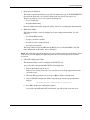
To Install a Drive in the HDD Cage
1. Perform steps 1 through 3 of the pre-installation instructions.
2. Remove the left-side cover.
3. Remove the front bezel.
4. Remove the HDD cage from the server:
The first two substeps below assume that there is a drive currently installed in the cage. If
the cage is empty, go directly to substep (c).
a. Disconnect the power cable from the rear of the drive.
b. Disconnect the data cable from the rear of the drive.
4-12
HP ProLiant ML110 Server Operations and Maintenance Guide
System Configuration
c. Remove the six Torx screws that secure the cage to the chassis.
Keep the screws for reinstalling the cage later.
d. Gently slide out the cage from the chassis.
e. If you are going to install the new hard disk in a drive bay that is previously empty,
remove four screws from the side of the chassis labeled ‘HDD SCREWS’.
Figure 4-11: Removing the HDD cage
5. Select a drive bay in the HDD cage where you want to install the new hard disk.
If necessary, pull out any previously installed drive by removing the four screws securing
the old drive to the cage, before sliding the drive out of the cage. You will be reusing
these screws when you install the new hard disk.
6. Install the new hard disk:
a. Slide the new hard disk into the selected bay.
b. If you are installing the new hard disk in a drive bay that is previously empty, use the
four screws you removed earlier from the side of the cage (step 4-e) to secure the
new drive.
If you are installing the new hard disk in a drive bay where there was a previously
installed drive, use the screws you removed from that old drive to secure the new
drive.
HP ProLiant ML110 Server Operations and Maintenance Guide
4-13
System Configuration
Figure 4-12: Installing a hard disk in the HDD cage
7. Install the HDD cage back into the chassis:
a. Guide the HDD cage into the chassis opening, with the cable connectors of the drive
facing the rear of the chassis, then push the cage all the way into the chassis.
b. Use the six Torx screws you removed earlier (step 4-c) to secure the cage to the
chassis.
c. Connect a power cable to its connector on the rear of the new HDD.
If there is any previously installed drive that is still in the cage, reconnect the power
cable of that drive.
d. Connect the data cable to its connector on the rear of the new HDD.
If there is any previously installed drive that is still in the cage, reconnect the data
cable of that drive.
Figure 4-13: Installing the HDD cage
8. Observe the post-installation procedures.
4-14
HP ProLiant ML110 Server Operations and Maintenance Guide
System Configuration
Mainboard Components
Processor
The mainboard’s CPU socket supports a single 478-pin Intel processor.
To Remove a Processor
1. Perform steps 1 through 3 of the pre-installation instructions.
2. Remove the left-side cover.
3. Lay the server on its side (components showing) for better access to the CPU socket.
4. If necessary, remove any accessory boards or cables that prevent access to the CPU
socket.
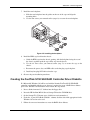
5. Remove the heat sink-cooling fan assembly:
a. Disconnect the CPU fan cable from the connector on the mainboard.
b. Depress then unhook the two heat sink retention levers.
c. Remove the heat sink-cooling fan assembly by lifting it away from the mainboard.
Lay down the heat sink-cooling fan assembly down in an upright position—with the
thermal patch facing upward. Do not let the thermal patch touch the work surface.
Figure 4-14: Removing the heat sink-cooling fan assembly
6. Remove the processor from its socket:
a. Depress then lift up the socket retention bar up to a 90° angle.
b. Grasp the processor by its edges and lift it out of its socket.
HP ProLiant ML110 Server Operations and Maintenance Guide
4-15
System Configuration
Figure 4-15: Removing the processor
7. Place the processor on a static-dissipating work surface or inside an anti-static bag.
To Install a Processor
1. If necessary, remove any previously installed processor from the CPU socket. Follow the
procedures in the preceding section.
To allow the heat sink to draw away as much heat as possible from the processor base, it
is required there be a tight connection between the contact surfaces—the heat sink base
and the top side of the processor. To ensure this, it is required that a thermal grease
compound be applied.
NOTE: For this server model, it is recommended that you use the ShinEtsu G751 brand of thermal
grease compound.
2. To apply the thermal grease compound:
a. Use a clean cloth dipped in rubbing alcohol to clean both contact surfaces. Wipe the
contact surfaces several times to make sure that there are no particles or dust
contaminants.
b. Apply the thermal grease compound to both contact surfaces.
c. Use the edge of a razor blade to spread out the grease throughout the entire contact
surface and lightly scrape out any excess grease. Make sure that only a very thin layer
is applied so that the contact surface is still visible.
CAUTION: Applying too much grease will cause a gap between the contact surfaces. This
means that the heat sink is not even in direct contact with the processor, and therefore its
capacity to draw out heat is greatly reduced. Applying too much grease could also make the
grease squish out from the sides and go all over the processor pins or to the mainboard base
once the heat sink is installed. This may cause electrical shorts that can damage your system.
3. Install the processor:
a. Depress then lift up the socket retention bar up to a 90° angle from the processor
base.
b. Holding the processor by its edges, align it over the empty CPU socket.
Make sure that pin-1 marker (indicated by the notched corner) of the processor is
align to hole 1 of the socket (on the bottom right corner).
c. Insert the processor into the socket.
4-16
HP ProLiant ML110 Server Operations and Maintenance Guide
System Configuration
d. Press down the socket retention bar to lock the processor in place.
Figure 4-16: Installing a processor
Once the processor is installed, the heat sink-cooling fan assembly must be reinstalled on
top of the processor. The thermal grease you applied on the contact surfaces of the heat
sink and the processor provides the necessary thermal bonding to allow the heat sink to
draw away heat from the processor.
CAUTION: To prevent overheating or a possible system crash, use only a heat sink-cooling
fan assembly specified for the HP ProLiant ML110 server model.
4. Reinstall the heat sink-cooling fan assembly:
a. Align then insert the heat sink-cooling fan assembly on top of the processor.
b. If possible, slide the assembly slightly from side to side to help squeeze out any air
pockets trapped in the paste and to ensure even coverage.
CAUTION: Do not to slide the assembly too much or you could smear some of the grease
onto the CPU or the motherboard, or even damage the CPU pins.
c. Press down the two heat sink retention levers to secure the assembly in place.
CAUTION: To avoid thermal overheating ensure that both levers are firmly fastened,
providing good contact between the heat sink and processor.
d. Connect the CPU fan cable to its connector on the mainboard.
CAUTION: Failure to connect the CPU fan cable to its connector may cause the server to
shut down with no messages displayed and possibly damage the processor.
HP ProLiant ML110 Server Operations and Maintenance Guide
4-17
System Configuration
Figure 4-17: Installing the heat sink-cooling fan assembly
5. Observe the post-installation procedures.
Memory
Your HP ProLiant server has four DIMM slots that support:
•
DDR 400 unbuffered ECC DIMMs in 256 MB, 512 MB, or 1GB configuration
•
Up to two DIMMs per channel, single-sided and/or double-sided
•
Byte masking on writes through data masking
•
Single-bit Error Correcting Code (or Error Checking and Correcting) on the system
memory interface
Memory Operating Modes
NOTE: In the following discussion, channel A corresponds to the DIMM1 and DIMM2 slots, while
channel B to the DIMM3 and DIMM4 slots. Refer to the “Mainboard Components” section on Chapter 2
for view of the mainboard layout.
The MCH (memory controller hub) of your server supports the following operation modes:
•
Single-channel mode (SC)
— Populate channel A only
— Populate channel B only
— Populate both channel A and B
If either only channel A or only channel B is populated, then the MCH is set to operate in
single-channel mode. Data is accessed in chunks of 64 bits (8B) from the memory
channels. If both channels are populated with uneven memory (DIMMs), the MCH
defaults to virtual single-channel (VSC) mode.
4-18
HP ProLiant ML110 Server Operations and Maintenance Guide
System Configuration
VSC occurs when both channels are populated but the DIMMs are not identical or there
is an odd number of identical DIMMs. The MCH behaves identical in both singlechannel and virtual single-channel modes (hereafter referred to as single-channel (SC)
mode).
In SC mode of operation, the populated DIMMs configuration can be identical or
completely different. In addition, for SC mode, not all the slots need to be populated. For
example, populating only one DIMM in channel A is a valid configuration for SC mode.
Likewise, in VSC mode odd number of slots can be populated. For Dynamic Mode
operation, the requirement is to have an even number or rows (side of the DIMM)
populated. In SC, dynamic mode operation can be enabled with one single-sided (SS),
two SS or two double-sided (DS). For VSC mode, both the channels need to have
identical row structures.
•
Dual-channel lock step mode (DS)
— DS linear mode
This mode is the normal mode of operation for the MCH.
•
Dynamic addressing mode
When the MCH is configured to operate in this mode, FSB-to-memory bus address
mapping undergoes a significant change compared to that of a linear operating mode
(normal operating mode). In non-dynamic mode, the row selection (row indicates the side
of a DIMM) via chip select signals is accomplished based on the size of the row. For
example, for a 512 MB, 16Mx8x4b has a row size of 512 MB selected by CS0# and only
four open pages can be maintained for the full 512 MB. This lowers the memory
performance (increases read latencies) if most of the memory cycles are targeted to that
single row, resulting in opening and closing of accessed pages in that row.
Dynamic addressing mode minimizes the overhead of opening/closing pages in memory
banks allowing for row switching to be done less often.
SC or DS modes can be enabled with/without dynamic addressing mode enabled.
Table 4-1 below summarizes the different memory controller operating modes.
Table 4-1: Memory Controller Operating Modes
Mode type
SC mode
Dynamic addressing
mode
Non-dynamic
addressing mode
Channel A only
Yes *
Yes
Channel B only
Yes *
Yes
Both channel A and B
Yes *
Yes
Yes
Yes *
DS mode
Note: (*) special cases – need to meet the requirements discussed in the “Dynamic addressing
mode” item above.
HP ProLiant ML110 Server Operations and Maintenance Guide
4-19
System Configuration
DIMM Population Guidelines
DIMM population guidelines are illustrated in the figures below.
Figure 4-18: Single-channel mode operation
Figure 4-19: Dual-channel mode operation
NOTE: While the four DIMM slots can accept different size DIMMs in any configuration, HP
recommends installing the smallest capacity module in slot 4 and progressively larger capacity modules
in slots 3, 2 and 1.
To Remove a DIMM
1. Perform steps 1 through 3 of the pre-installation instructions.
2. Remove the left-side cover.
3. Lay the server on its side (components showing) for better access to the DIMM slots.
4. If necessary, remove any accessory boards or SCSI cables that prevent access to the
DIMM slots.
5. Locate the DIMM you want to remove.
6. Remove the selected DIMM:
a. Completely open the holding clips securing the DIMM.
This forces the DIMM up in the slot and makes it easier to remove.
b. Gently pull the DIMM upward to remove it from its slot.
4-20
HP ProLiant ML110 Server Operations and Maintenance Guide
System Configuration
Figure 4-20: Removing a DIMM
7. Place the DIMM on a static-dissipating work surface or inside an anti-static bag.
To Install a DIMM
1. Locate an empty DIMM slot on the mainboard.
2. Remove a DIMM from its protective container, handling the module by its edges.
If necessary, lay it on an anti-static surface until you are ready to install it.
3. Install the DIMM:
a. Orient the DIMM so that the notch on its bottom edge aligns with the keyed surface
of the DIMM slot, then press the DIMM fully into the slot.
The DIMM slots are structured to ensure proper installation. If you insert a DIMM
but it does not fit easily into the slot, you may have inserted it incorrectly. Reverse
the orientation of the DIMM and insert it again.
b. Firmly press the holding clips inward to secure the DIMM in place.
If the holding clips do not close, the DIMM is not inserted correctly.
Figure 4-21: Installing a DIMM
4. Observe the post-installation procedures.
HP ProLiant ML110 Server Operations and Maintenance Guide
4-21
System Configuration
PCI Cards
The HP ProLiant ML110 server supports five PCI bus slots with two separate bus channels:
•
Two 32-bit/33 MHz 5V PCI bus slots (PCI1 and PCI5)
•
Three 64-bit/66 MHz 3.3V PCI-X bus slots (PCI2 to PCI4)
To Install a PCI Card
1. Perform steps 1 through 3 of the pre-installation instructions.
2. Remove the left-side cover.
3. If necessary, remove any accessory boards or cables that prevent access to the PCI slots.
4. Locate an empty PCI slot on the mainboard.
5. Remove the PCI card from its protective packaging.
If necessary, lay it on an anti-static surface until you are ready to install it.
6. Install the PCI card:
a. Press the retention clip of the slot cover opposite the selected PCI slot.
b. Pull out the slot cover. Keep it for reassembly later.
Figure 4-22: Removing a PCI slot cover
c. Slide the PCI card into the selected slot and press it down to seat it properly.
d. Firmly press the retention clip until it snaps into place.
e. Connect the necessary cable to the card.
4-22
HP ProLiant ML110 Server Operations and Maintenance Guide
System Configuration
Figure 4-23: Installing a PCI card
7. Observe the post-installation procedures.
Battery
Your HP ProLiant server is equipped with a 3V 200 mAh internal lithium battery.
To Replace the Battery
WARNING: Note the following reminders when replacing the battery.
•
Replace the battery with the same type as the product's battery we recommend.
Use of another battery may present a risk of fire or explosion.
•
Batteries may explode if not handled properly. Do not disassemble or dispose of
them in fire. Keep them away from children and dispose of used batteries
promptly. Dispose of used batteries according to manufacturer's instructions.
1. Perform steps 1 through 3 of the pre-installation instructions.
2. Remove the left-side cover.
3. Lay the server on its side (components showing) for better access to the battery socket.
4. If necessary, remove any accessory boards or SCSI cables that prevent access to the
battery socket.
5. Replace the battery:
a. Insert a small flat-blade screwdriver or a similar tool between the battery and spring
latch to dislodge the battery from its socket.
b. Lift up the battery to remove it.
HP ProLiant ML110 Server Operations and Maintenance Guide
4-23
System Configuration
c. Insert a new battery with the positive sign (+) facing up, and ensure that it is seated
completely.
Ensure the spring latch is in place, and holds the battery firmly.
Figure 4-24: Replacing the battery
6. Observe the post-installation procedures.
Power Supply Unit (PSU)
Located on the rear panel of the server is a single standard autoranging 350-watts PSU with
PFC (power supply correction) function.
WARNING: Take note of the following reminders to reduce the risk of personal injury
from electric shock hazards and/or damage to the equipment.
•
Installation of power supply modules should be referred to individuals who are
qualified to service server systems and are trained to deal with equipment capable
of generating hazardous energy levels.
•
DO NOT open the power supply modules. There are no serviceable parts inside the
module.
To Replace the Default PSU
1. Perform steps 1 through 3 of the pre-installation instructions.
2. Remove the left-side cover.
3. Lay the server on its side.
4. Remove the default PSU from the server:
a. Disconnect the PSU cables from their mainboard connectors (CN1and CN2).
Disconnect the power cables of all installed drives from the PSU.
b. While supporting the PSU with one hand, remove the four screws securing the PSU
to the chassis.
WARNING: Be sure to support the PSU with your hands when removing the screws
securing it to the chassis. The PSU is heavy and could hurt you or damage
components on the mainboard.
4-24
HP ProLiant ML110 Server Operations and Maintenance Guide
System Configuration
c. Gently slide the PSU out of the chassis.
Figure 4-25: Removing the PSU
5. Install a new PSU:
a. Align the new PSU to the power supply bay inside the chassis.
b. Secure the PSU in place using the four screws you removed earlier.
c. Connect the PSU cables to their mainboard connectors (CN1 and CN2).
Connect the power cables of all installed drives to the PSU.
Figure 4-26: Installing a PSU
6. Observe the post-installation procedures.
HP ProLiant ML110 Server Operations and Maintenance Guide
4-25
System Configuration
System Fan
A new system fan can be installed to allow the server to operate properly in case the default
system fan becomes defective.
To Replace the Default System Fan
1. Perform steps 1 through 3 of the pre-installation instructions.
2. Remove the left-side cover.
3. Remove the default system fan:
a. Disconnect the system fan cable from its power connector (SYSFAN1) on the
mainboard.
b. While supporting the system fan with one hand, push a finger through the middle
ventilation hole on the rear panel. This will dislodge the fan from the chassis.
WARNING: Be sure to support the system fan with your hands when dislodging it from
the chassis. The fan could fall onto the mainboard or an accessory board causing
damage if not supported.
c. Slide the system fan upward to disengage the frame tabs from the chassis.
d. Pull the system fan away from the chassis.
Figure 4-27: Removing a system fan from the server
4-26
HP ProLiant ML110 Server Operations and Maintenance Guide
System Configuration
4. Detach the old fan from its frame by unclasping the four retention latches on the frame
before pulling the fan away.
Figure 4-28: Removing a system fan from its frame
5. Install the new fan to its frame by aligning the pegs on the frame to their corresponding
notch on the fan, then firmly press the two together until the retention latches snap into
place.
Figure 4-29: Installing a system fan to its frame
6. Install a new system fan:
a. Align the tabs on the system fan frame to their chassis notch.
b. Slide the system fan downward to secure the tabs to the chassis.
HP ProLiant ML110 Server Operations and Maintenance Guide
4-27
System Configuration
c. Connect the system fan cable to its power connector (SYSFAN1) on the mainboard.
Figure 4-30: Installing a system fan on the server
7. Observe the post-installation procedures.
Server Configuration
The following sections describe how to configure the HP ProLiant ML110 server using the
following resources:
•
HP ProLiant ML110 Server Startup CD-ROM
This CD-ROM allows you to access and copy the needed utilities and drivers to flexible
diskettes, which can be used to configure the server. Some NOS drivers are copied
directly to the server from the Startup CD.
To run the Startup CD, locate a system with NOS installed and has a CD-ROM drive.
Place the disc in the system’s CD-ROM drive. The CD should auto-start, but if it does
not, start it by opening the Startup.htm file found at the root level of the Startup CD.
NOTE: The HP ProLiant ML110 Server Startup CD is not bootable.
•
NOS drivers
The NOS drivers are copied from the Startup CD to diskettes. The instructions for
installing specific NOS and their respective drivers are provided in the HP ProLiant
ML110 Server NOS Installation Guide. Use this guide to create and copy the appropriate
drivers onto the required diskettes. In some cases you will use the diskettes to load the
appropriate drivers onto the server, or load the drivers directly from the Startup CD onto
the server.
4-28
HP ProLiant ML110 Server Operations and Maintenance Guide
System Configuration
•
Diagnostics for Windows
This utility is installed from the Startup CD. For instructions, refer to the README.TXT
file inside the Diagnostics for Windows folder in the Startup CD. Diagnostics for
Windows provides an easy-to-use hardware diagnostic for:
— Server verification
— Rapid troubleshooting
For more information on this diagnostic utility, refer to its accompanying documentation.
•
BIOS Setup Utility
This firmware utility is used to configure the system configuration defaults. Use this
utility to:
— Set default BIOS settings
— Set the system date and time
— Set and clear the system passwords
— Set device boot priority
The Setup Utility used by the HP ProLiant ML110 server is Phoenix BIOS v4.06. For
more information on this utility, refer to Chapter 5.
NOTE: The Setup Utility automatically detects most of the hardware devices you install, but you should
verify that the server has properly recognized the options after you have installed all of the optional
accessories.
•
LSI SCSI Configuration Utility
This firmware utility is used to configure the LSI SCSI card.
Access the utility and perform initial SCSI card configuration:
1. Turn on the monitor and the server.
If the server is already turned on, save your data and exit all open applications, then
restart the server.
2. When the HP logo banners on-screen, press Esc to shift to text mode boot.
3. At the LSI SCSI Configuration Utility copyright page, the message prompt below
displays.
<<<Press F8 for configuration options>>>
4.
Press F8 to display the configuration options.
If you fail to press F8 and POST is initialized, you will need to restart the server.
HP ProLiant ML110 Server Operations and Maintenance Guide
4-29
System Configuration
5.
Select a configuration option by pressing the corresponding item number.
•
Tape-based One Button Disaster Recovery (OBDR)
Select this option to perform recovery procedures for a SCSI drive that supports
OBDR function.
•
Multi-initiator Configuration
Select this option to perform initial setup SCSI configuration.
•
Exit
Select this option to close the utility. System will automatically reboot.
OBDR Function
a. Press 1 to select the OBDR option.
The utility will scan your server for any installed SCSI tapes and display the results.
A message prompt will be shown below the scan results.
<<<Please choose the NUM of the tape drive
to place into OBDR mode>>>
b. Type the NUM value corresponding to the SCSI tape you want to place into OBDR
mode.
Auto-configuration will be initialized after which the system will automatically
reboot.
Multi-initiator Configuration
a. Press 2 to select the Multi-initiator Configuration option.
The utility will scan your server for any installed SCSI cards and display the results.
A message prompt will be shown below the scan results.
Enter choice (y/Exit x)
where y is the card number.
b. Enter the number for the card you want to configure.
You will be prompted to change the card ID.
c. Enter the new card ID.
You will be prompted to confirm the status of the Reset SCSI BUS at IC
Initialization parameter.
By default, this parameter is enabled. Press Y to disable the parameter.
d. Press x to save the configuration settings and close the utility.
The system will automatically reboot.
4-30
HP ProLiant ML110 Server Operations and Maintenance Guide
5
BIOS Setup Utility
This chapter provides information on BIOS Setup Utility and instructions on how to use it to
configure the system.
NOTE: For ease of reading, BIOS Setup Utility will be simply referred to as “Setup Utility” or “Setup” in
this guide.
Setup Utility Overview
BIOS Setup Utility is a hardware configuration program built into your system's Basic
Input/Output System (BIOS). Since most systems are already properly configured and
optimized, there is normally no need to run this utility. You will need to run this utility under
the following conditions:
•
When changing the system configuration including:
— Defining the diskette drive
— Defining the serial or parallel (COM/LPT) ports to prevent any conflicts
— Setting the system time and date
— Configuring the hard drives
— Specifying the boot device sequence
— Configuring the power management modes
— Setting up system passwords or making other changes to the security setup
•
When a configuration error is detected by the system and you are prompted ("Run Setup"
message) to make changes to the BIOS settings.
NOTE: If you repeatedly receive “Run Setup” messages, the battery may be defective. In this case, the
system cannot retain configuration values in CMOS. Ask a qualified technician for assistance.
The Setup Utility loads the configuration values in a battery-backed nonvolatile memory
called CMOS RAM. This memory area is not part of the system RAM, which allows
configuration data to be retained when power is turned off. The values take effect when the
system is booted. POST uses these values to configure the hardware. If the values and the
actual hardware do not agree, POST generates an error message. You must run this utility to
change the BIOS settings from the default or current configuration.
HP ProLiant ML110 Server Operations and Maintenance Guide
5-1
BIOS Setup Utility
Accessing the Setup Utility
1. Turn on the monitor and the server.
If the server is already turned on, save your data and exit all open applications, then
restart the server.
2. During POST, press F2.
If you fail to press F2 before POST is completed, you will need to restart the server.
The first page to be displayed will be the Main menu showing the Setup Utility’s menu
bar.
PhoenixBIOS Setup Utility
Advanced
Security
Power
Main
System Time
System Date:
[16:19:20]
[03/02/2003]
Legacy Diskette A:
[1.44/1.25
IDE
IDE
IDE
IDE
Channel
Channel
Channel
Channel
0
0
1
1
Master
Slave
Master
Slave
Boot
Exit
Item Specific Help
<Tab>, <Shift-Tab>, or
<Enter> selects field
MB 3½”]
6449 MB
None
CD-ROM
None
Memory Cache
Boot Features
System Memory
Extended Memory
F1 Help
Esc Exit
640 kB
31744 kB
↑↓ Select Item
← Select Menu
-/+ Change Values
F9 Setup Defaults
Enter Select Sub-Menu F10 Save and Exit
Figure 5-1: Setup Utility’s Main menu
Setup Utility Menus
The Setup Utility’s menu bar has six menu selections. The table on the next page lists these
menus and their corresponding functions. Refer to the online help displayed on the left side of
the Setup screen for an explanation of the currently displayed setting.
5-2
HP ProLiant ML110 Server Operations and Maintenance Guide
BIOS Setup Utility
Table 5-1: Setup Utility Menus
Menu
Function
Main
Use this menu to set the system time and date, select the FDD type, configure the
IDE devices, define memory caching, and set bootup mode.
Advanced
Use this menu to reset configuration data, enable hardware protection, and define
the settings for the USB Legacy Support, console redirection, and ACPI BIOS
functions. You can also use this menu to configure the following items:
•
SCSI and PATA devices
•
USB and integrated I/O ports
•
Chipset and processor options
•
PCI slots
CAUTION: Be cautious in setting parameter values in this menu as any incorrect
value may cause the system to malfunction.
Security
Use this menu to safeguard and protect the system from unauthorized use by
setting up access passwords.
Power
Use this menu to set the power-saving options (they are NOS dependant), and
power-up options. This menu enables ACPI features only available with certain
NOS.
Boot
Use this menu to set the preferred drive sequence boot order of the mass storage
devices and PCI cards during system bootup.
Exit
Displays the various options to quit from the Setup Utility.
To Move Around the Setup Screen
•
Press the right-arrow and left-arrow keys to move between selections on the menu bar.
•
Press the up-arrow and down-arrow keys to move between parameters on each menu
screen.
The currently selected parameter will be highlighted. A description of the selected
parameter and available options is displayed on the Item Specific Help column on the
right side of the screen.
•
Certain parameters ask you to choose from a list of entries. In such cases, press the plus
(+) or minus (-) keys repeatedly to display each possible entry, or the Enter (or Return)
key to choose from a pop-up menu.
A parameter that is enclosed in square brackets [ ] is user-configurable.
Grayed-out parameters are not user-configurable for one of the following reasons:
— The parameter is auto-configured or auto-detected.
— The parameter is informational only.
— The parameter is password-protected and is accessible only by the User or
Administrator.
HP ProLiant ML110 Server Operations and Maintenance Guide
5-3
BIOS Setup Utility
•
Small arrow pointers ( ) precede some parameter names. This means that there are
available submenus. To view these submenus, select the primary parameter with the
arrow pointer and press Enter. The submenu screen then displays in place of the current
screen.
•
Esc is the exit key. If you press this key:
— On one of the primary menu screens, the Exit menu displays.
— On a submenu, the previous screen displays.
— When you are making selections from a pop-up menu, closes the pop-up without
making a selection.
•
Press F1 for Setup Help.
•
Press F9 to load default system values.
•
Press F10 to save changes and close the Setup Utility.
Recording BIOS Settings
Record the settings in the Setup Utility. If the custom values ever need restoring (after a
CMOS clear, for example), you must run the Setup Utility and enter your custom settings
again. A record of any custom settings will make this much easier.
System Summary Screen
The System Summary Screen displays basic and important information about the current
server configuration and is necessary for troubleshooting and may be required when asking
for technical support. These information include:
•
CPU (speed, cache size, type, microcode)
•
System BIOS version
•
System memory size
•
Video memory size
•
I/O ports available
•
Installed mass storage devices
•
PCI slots available
•
Wake On LAN (WOL) status
It is recommended that you check this screen during the initial system setup and each time
you install, remove, or upgrade accessories.
5-4
HP ProLiant ML110 Server Operations and Maintenance Guide
BIOS Setup Utility
To View the System Summary Screen
You first need to enable the display of the System Summary Screen during bootup. Follow
the steps below.
1. In the Main menu screen, select Boot Features.
The Boot Features submenu is displayed.
2. Select Summary Screen.
3. Press the plus (+) or minus (-) key to set the parameter to Enabled.
4. Press F10 to save the changes you made and close the Setup Utility.
5. Reboot the server.
The System Summary Screen is displayed briefly at the end of POST.
Figure 5-2: System Summary Screen
6. Press the Pause/Break key to continue displaying the screen until another key is pressed.
7. Press any key to continue with the system bootup.
System Passwords
The Security menu lets you set system passwords that would provide different levels of
protection for the server. There are three types of passwords that you can set:
•
Supervisor password
Entering this password will allow the user to access and change all settings in the Setup
Utility.
HP ProLiant ML110 Server Operations and Maintenance Guide
5-5
BIOS Setup Utility
•
User password
Entering this password will only allow the user to access and modify certain items in the
Setup Utility. These items include:
— Main menu: System Time and System Date
— Security menu: Set User password
•
Power-on password
When the Password on Boot parameter in the Security menu is enabled, either the
supervisor or the user password will be required to boot up the server.
To Set a System Password
NOTE: A Supervisor password should be set first before a User password can be defined.
1. In the Security menu screen, select a set password parameter—Set User Password or Set
Supervisor Password, then press Enter.
A password box will display.
Figure 5-3: Set Password box
2. Type a password.
The password may consist of up to eight alphanumeric characters (A-Z, a-z, 0-9).
3. Retype the password to verify the first entry, then press Enter.
4. If you want the new password to be check during bootup, select the Password on Boot
parameter on the Security menu and set it to Enabled.
5. Press F10 to save the password and close the Setup Utility.
After setting the password, the system automatically changes the chosen password
parameter to Enabled.
To Change a System Password
1. In the Security menu screen, select a set password parameter—Set User Password or Set
Supervisor Password, then press Enter.
A password box will display.
2. Type the original password then press Enter.
3. Type a new password then press Enter.
5-6
HP ProLiant ML110 Server Operations and Maintenance Guide
BIOS Setup Utility
4. Retype the new password to verify the first entry then press Enter again.
5. Press F10 to save the password and close the Setup Utility.
To Remove a System Password
1. In the Security menu screen, select a set password parameter—Set User Password or Set
Supervisor Password, then press Enter.
A password box will display.
2. Type the original password then press Enter.
3. Press Enter twice without entering anything in the new and confirm password fields.
4. Press F10 to save the changes you made and close the Setup Utility.
The system automatically sets the corresponding password parameter to Clear.
To Reset a System Password
If you have forgotten the User password or the Supervisor password, the server will continue
to function normally but you will not be able to access the Setup Utility.
If you have enabled the Password on Boot parameter and have forgotten both the User
password and the Supervisor password, you will not be able to reboot the server.
If you have forgotten the User password, you can use the Supervisor password to reset it for
you. However, if it is the Supervisor password that you have forgotten, you can only reset it
by clearing the hardware password dip switch.
To reset your password:
1. Perform the pre-installation instructions listed in Chapter 4.
2. Locate the dip switch (SW1) on the mainboard.
Go to Chapter 2 for a view of the mainboard layout.
3. Identify SW1-3 of the dip switch.
By default, SW1-3 is set to the Off position.
4. Set SW1-3 to the On position.
5. Reinstall the left-side cover as described in Chapter 4.
6. Reconnect only the power cord.
7. Turn on the server.
The system would have already cleared any reference to the lost password. Perform the
following steps to reset SW1-3 to its default position.
8. Power down the server and disconnect the power cable.
9. Remove the left-side cover as described in Chapter 4.
10. Repeat steps 2 through 3.
HP ProLiant ML110 Server Operations and Maintenance Guide
5-7
BIOS Setup Utility
11. Set SW1-3 to its default Off position.
12. Perform the post-installation instructions listed in Chapter 4.
To set a new batch of system passwords, refer to the “To Set a System Password” section.
Closing the Setup Utility
The Exit menu provides several options to close the utility. These options are listed on the
table below.
Table 5-2: Setup Utility Exit Options
Option
Description
Exit Saving Changes
Saves changes made and close the Setup Utility.
Exit Discarding Changes
Discards changes made and close the Setup Utility.
Load Setup Defaults
Loads the factory-default settings for all Setup parameters.
Discard Changes
Discards all changes made to the Setup Utility and loads previous
configuration settings.
Save Changes
Saves all changes made to the Setup Utility.
BIOS Update and Recovery
The following sections provide instructions on how to update/recover BIOS settings.
To Create the BIOS Update/Recovery Diskette
1. Prepare a blank and formatted 3.5-inch diskette.
2. Insert this diskette in to the FDD of any Windows PC with an HTML browser that is
connected to the Internet.
3. On HP’s website at www.hp.com locate and download the latest HP ProLiant ML110
server BIOS to the server’s hard drive.
4. Double-click the downloaded file and follow the instructions to extract the BIOS update
to the blank diskette you earlier prepared.
5. Label, date, and save this diskette as BIOS Update/Recovery.
NOTE: If you do not have convenient access to the Internet, you can create the BIOS
Update/Recovery diskette by using the HP ProLiant ML110 Server Startup CD-ROM. Please note that
the Startup CD may not provide the most recent BIOS. To create the BIOS Update/Recovery diskette,
run the Startup CD on any Windows PC with an HTML browser and follow the menu instructions.
5-8
HP ProLiant ML110 Server Operations and Maintenance Guide
BIOS Setup Utility
To Update BIOS
HP regularly posts a new version of the HP ProLiant ML110 server BIOS on their website at
www.hp.com to improve the server’s performance.
To update the server’s BIOS Setup Utility with the latest version:
1. Create the BIOS Update/Recovery diskette as described in the previous section.
2. Insert the BIOS Update/Recovery diskette into the server’s FDD.
3. Reboot the server to the BIOS Update/Recovery diskette.
This action will automatically flash the BIOS from the diskette to the server.
4. Remove the BIOS Update/Recovery diskette and then reboot the server.
5. During POST, press F2 to access the Setup Utility.
6. Make the necessary changes (such as system time, passwords, or boot device priority).
7. Press F10 to save the changes you made and close the Setup Utility.
To Reset the BIOS Settings
The default BIOS settings have been selected to optimize the HP ProLiant ML110 server’s
performance.
To reset the BIOS settings to the factory defaults:
1. Reboot the server in a normal manner.
2. During POST, press F2 to access the Setup Utility.
3. Press F9 to load the default values.
NOTE: It is recommended that you take note of the system setup before making any modifications to
the BIOS settings.
4. Press F10 to save the changes you made and close the Setup Utility.
To Perform BIOS Recovery
Perform this procedure if the BIOS flash ROM has become corrupted. Your HP ProLiant
ML110 server supports a boot block function that lets you perform a recovery routine that
would:
•
Initialize system hardware and run the flash application program.
•
Boot the server to the BIOS Recovery/Update diskette.
•
Load the flash ROM update program from the BIOS Recovery/Update diskette into the
system memory.
•
Re-program the system BIOS ROM with a copy of the original or upgraded system BIOS
from the BIOS Recovery/Update diskette.
HP ProLiant ML110 Server Operations and Maintenance Guide
5-9
BIOS Setup Utility
To perform BIOS recovery:
1. Create the BIOS Recovery/Update diskette as described earlier in this chapter.
2. Perform the pre-installation instructions listed in Chapter 4.
3. Locate the dip switch (SW1) on the mainboard.
Refer to Chapter 2 for a view of the mainboard layout.
4. Identify SW1-2 of the dip switch.
By default, SW1-2 is set to the Off position.
5. Set SW1-2 to the On position.
6. Reinstall the left-side cover as described in Chapter 4.
7. Reconnect only the power cord.
8. Insert the BIOS Recovery/Update diskette into server’s FDD.
9. Turn on the server.
The server boots from the diskette and then flashes the BIOS. The screen remains blank
during this process. When the BIOS recovery is complete, a long beep is sounded and the
server shuts down automatically.
10. Disconnect the power cable.
11. Remove the BIOS Recovery/Update diskette from the FDD.
12. Remove the left-side cover as described in Chapter 4.
13. Repeat steps 3 through 4.
14. Set SW1-2 to its default Off position.
15. Perform the post-installation instructions listed in Chapter 4.
16. During POST, press F2 to access the Setup Utility.
17. Make the necessary changes (such as system time, passwords, or boot device priority).
18. Press F10 to save the changes you made and close the Setup Utility.
Clearing CMOS
You may need to clear the BIOS configuration (CMOS) if the configuration has been
corrupted, or if incorrect settings made in the Setup Utility have caused error messages to be
unreadable. Clearing CMOS does not invalidate previously set system passwords.
1. Perform the pre-installation instructions listed in Chapter 4.
2. Locate the dip switch (SW1) on the mainboard.
Refer to Chapter 2 for a view of the mainboard layout.
3. Identify SW1-1 of the dip switch.
By default, SW1-1 is set to the Off position.
5-10
HP ProLiant ML110 Server Operations and Maintenance Guide
BIOS Setup Utility
4. Set SW1-1 to the On position.
This will clear the CMOS memory.
5. Switch SW1-1 back to its default Off position.
6. Perform the post-installation instructions listed in Chapter 4.
7. During POST, press F2 to access the Setup Utility.
8. Press F9 to load the system default values.
9. Press F10 to save the changes you made and close the Setup Utility.
Setting Hardware Protection
You have the option to lock and unlock some of the hardware devices of the server. Do this to
set the access limit for these items.
1. In the Advanced menu screen, select the Hardware Protection parameter, then press
Enter.
The Hardware Protection submenu displays.
2. Select the hardware item you want to lock.
3. Press the plus (+) or minus (-) key to set the selected hardware to Lock.
4. Press F10 to save the changes you made and close the Setup Utility.
HP ProLiant ML110 Server Operations and Maintenance Guide
5-11
6
System Maintenance
This chapter provides information on preventive system maintenance, as well as
troubleshooting procedures for common system problems.
Preventive Maintenance Procedures
Refer to the following table for preventive maintenance procedures you should observe in
cleaning the server.
WARNING: Be sure to turn off power to the server when doing any preventive
maintenance procedures.
Table 6-1: Preventive Maintenance Procedures
Component
Schedule
Procedure
Keyboard
Regularly
Dust with damp, lint-free cloth.
CAUTION: Do NOT use petroleum-based cleaners (such as lighter fluid) nor
cleaners containing benzene, trichloroethylene, ammonia, dilutes ammonia, or
acetone. These chemicals could damage the keyboard's plastic surfaces.
Monitor
screen
Regularly
Refer to the monitor's manual for maintenance procedures.
Mouse
Regularly
To clean a regular mouse (with rubber ball):
1.
Remove the circular cover underneath the mouse.
2.
Take out the rubber ball and wipe it with a soft, damp cloth.
3.
Put the ball back and attach the cover.
To clean an optical mouse:
Refer to the documentation that came with your mouse for maintenance
instructions.
Tape drive
heads
Monthly
Cooling fans
and grilles
Every 6
months
Use the Magnetic Head Cleaning Solution found in the 92193M Master Clean Kit.
NOTE: HP recommends the periodic cleaning of tape heads, capstans, and
guides on HP tape drive units and those products using high-density data
cartridges and mini-data cartridges. These maintenance procedures prolong tape
and head life and helps reduce read/write errors due to dust and oxide.
Check cooling fan operation and clean the air intake openings on the chassis by
removing any dust, lint, and other obstructions to airflow.
HP ProLiant ML110 Server Operations and Maintenance Guide
6-1
System Maintenance
Troubleshooting Procedures
Refer to the following sections for the information you need to deal with possible system
problems.
Troubleshooting Tools
If you are having problems operating your HP ProLiant ML110 server, refer to the table
below for a list of resources you can use.
Table 6-2: Troubleshooting Tools
Resources
Help contents
HP’s website at
www.hp.com
Access the most comprehensive support material for HP servers including:
•
Latest support news - product and support information
•
Drivers and software downloads
•
Manuals - Easy installation and configuration instructions
•
HP Instant support - Fast, web-based support that is automated and provides
quick diagnosis and resolution of most computing problems.
•
Step-by-step guides for system troubleshooting.
NOTE: Information on HP’s website do not generally cover third-party components or
devices. Refer to the documentation that comes with the third-party device for
diagnostic and troubleshooting information.
•
Technical information - data sheets, application notes, configuration guides,
installation tips, product papers, reference material
•
Compatibility issues - HP accessories, OS/NOS, HP and third-party parts
compatibility information
•
Parts and service - information on replacement parts, system structure, and
hardware configuration
•
Tape backup support for HP's SureStore Tape Backup products
•
Training programs - HP STAR worldwide training and certification program
•
HP server registration
•
Warranty and enhanced services - guide to warranty services
•
Proactive notification - HP will e-mail your custom information when it is available.
•
Contacts - information on how to get help or provide feedback
HP ProLiant ML110 Server
Startup CD-ROM
Contains a utility for troubleshooting purposes.
This "System Maintenance"
chapter
Refer to this chapter for troubleshooting instructions for common system problems as
well as information on preventive system maintenance.
6-2
Diagnostics for Windows is an easy-to-use hardware diagnostic for server verification,
burn-in, and rapid troubleshooting. For more information on how to use this utility, refer
to its accompanying documentation.
HP ProLiant ML110 Server Operations and Maintenance Guide
System Maintenance
Troubleshooting Procedures
The following sections provide detailed instructions on how to perform simple
troubleshooting tasks in managing common server problems.
CAUTION: If a troubleshooting procedure requires configuring the system hardware, read the
“Pre- and Post-installation Procedures” section in Chapter 4, and the ESD precautions listed
in Appendix B. Failure to observe the procedures described in these sections may result to
damage to the server unit, loss of information, or bodily harm.
NOTE: If a troubleshooting procedure requires accessing a BIOS Setup Utility menu, reboot the server,
then during POST, press F2.
If after performing these procedures, the problem condition still persists, contact your HP
Customer Support provider for technical support.
Technical Support
If you need any technical support on operating your server, do any of the following:
•
Contact an HP authorized service provider in your area. For information on how and
where to contact these service centers in your area, refer to
http://e-support.hp.com.cn/Support/product-item.asp.
•
Go to HP’s website at www.hp.com. Refer to the topics listed earlier regarding this
website.
•
If you need immediate telephone support, contact the HP Customer Support Center.
— US/Canada phone support: 1-800-652-6672
— For all other countries, visit www.productfinder.support.hp.com/tps/CLC and click
English to see an expanded list of countries.
Troubleshooting Checklist
The following are general items you need to check whenever a problem condition occurs.
•
Make sure the server is properly configured.
Many server problems are the result of incorrect system and SCSI subsystem
configuration settings. Check the system settings using the BIOS Setup Utility.
•
If it is a network-related error, determine if the user has enough memory and hard disk
drive capacity. Run the diagnostics for the NIC. Consult the documentation for your
server’s particular NOS.
•
If it is a hardware error, follow the instructions to log users off the LAN and power down
the server. Reboot and watch for any POST error messages and listen for any beep codes
as the server goes through POST.
Refer to the “POST Error Indicators” section in Chapter 7 for more information.
HP ProLiant ML110 Server Operations and Maintenance Guide
6-3
System Maintenance
•
If the server passes POST, use the Diagnostics for Windows utility to further test the
hardware. Use this utility whenever possible to detect hardware problems.
For more information on this diagnostic tool, refer to its accompanying documentation.
•
For problems with the disk array controller board, refer to the appropriate HP SCSI
RAID manual.
Determining the Cause of a Problem Condition
To isolate the cause of a problem condition:
1. Verify the error.
Make sure it is not an erroneous error message. Is the error repeatable? Is the error
message affecting the HP server's operation or performance?
2. Check the most recently added items added, both hardware and software.
3. Remove any third-party components.
4. Make sure the server’s BIOS is updated to the latest version posted in HP’s website.
Flashing/updating the system BIOS and clearing CMOS will resolve many different
issues. Refer to Chapter 5 for related procedures.
5. Make sure all firmware/BIOS revisions on any controllers are kept current.
6. Make sure that only HP-provided drivers are used for all HP devices used in the server.
This includes HP drivers for the initial installation of any NOS that is supported by the
server.
7. Check all cables and power connections, including those in the rack.
8. If the server is not powering on, unplug the AC power cord(s) and wait for 20 seconds
then plug the AC power cords in again and restart the server. Check for normal operation.
9. Verify that all cables and boards are securely plugged into their appropriate connectors
and slots.
10. If the problem still persists, simplify the server's configuration. The minimum
requirements include:
•
Monitor
•
Keyboard
•
Mouse
•
One hard drive (may need to disconnect for hardware troubleshooting)
•
CD-ROM and flexible disk drive (you may need to disconnect these items for
hardware troubleshooting)
11. Reconnect the power cords and power on the server.
12. If the server is operational, power back down and reinstall one component at a time and
power on the server after the installation of each component to try and determine which
component is causing the problem.
6-4
HP ProLiant ML110 Server Operations and Maintenance Guide
System Maintenance
13. Once the cause of the problem condition is determined, refer to the next section for
detailed instructions on how to troubleshoot it.
If after performing the steps above, the cause of the problem condition remains unknown,
seek HP technical support. Refer to the “Technical Support” section earlier in this chapter.
Specific Troubleshooting Procedures
Refer to the instructions below for troubleshooting a particular server problem.
General Server Problems
The server stops working (hangs up).
If the server hangs before the POST is completed, the problem is probably due to a hardware
problem or failure.
If the server hangs after POST is completed, the problem is possibly due to an incorrectly
configured or corrupt driver, operating system, or application program, or a media (disk
drive) error.
To resolve the problem:
1. Review the items under the “Troubleshooting Checklist” section earlier in this chapter.
2. Try to verify exactly when during POST did the server hang up.
For example, is the server stopping at the memory count or a SCSI controller? Look for
any error messages and listen for any beep codes and make note of them for further
assistance in troubleshooting the problem.
3. If your server supports the Hardware Event Log function, check it for any hardware
inconsistency.
4. If the failure persists, try removing any recently added hardware and see if the problem
still exists.
5. If the problem has disappeared, add one removed hardware component at a time back
into the server to try and verify which hardware component is causing the problem.
For further assistance, contact the HP Customer Support Center before replacing any parts.
The server passes POST, but does not function.
•
If an error message displays, read the message and refer to the “POST Error Indicators”
section in Chapter 7 for troubleshooting suggestions.
•
If there is no error message:
1. If you are an experienced user, verify the server is configured correctly using the
BIOS Setup Utility.
HP ProLiant ML110 Server Operations and Maintenance Guide
6-5
System Maintenance
2. If the server still does not work:
a. Power off the server and remove all external peripherals, except the monitor and
keyboard.
b. Test the server for normal operation now.
c. If the server still does not work, proceed to step 3.
3. Turn off the monitor, the server, and all external devices, and check the internal
hardware by performing the steps below:
a. Perform steps 1 through 3 of the pre-installation instructions listed in Chapter 4.
b. Remove the left-side cover as described in Chapter 4.
c. Remove the front bezel as described in Chapter 4.
d. Check that all accessory boards are firmly seated in their respective slots.
e. Make sure all disk drive power and data cables are securely and properly
connected.
f.
Check that all the mass storage devices meet the specification of your HP server.
g. Verify that all installed memory modules are HP-approved modules and they are
properly seated.
h. Observe the post-installation procedures described in Chapter 4.
i.
Turn on the server and the monitor.
j.
Check for an error message or beep code.
If an error message displays, read and note the message, then go to the “POST
Error Indicators” section in Chapter 7 for troubleshooting suggestions.
4. Reboot the server.
5. Run the Diagnostics for Windows utility from the Startup CD and verify the server’s
hardware integrity.
The message "Operating system not found" displays.
1. Check for a non-bootable diskette in the FDD. If found, remove the diskette from the
drive.
2. Check for a tape in the tape drive. If found, remove the tape cartridge from the drive.
3. Turn on the server.
4. If the message still displays, run the BIOS Setup Utility and verify that the device boot
order settings are correct.
5. If a disk array controller is being used and the NOS is installed on a hardware
array/container, verify that the array/container is in an optimal state by accessing and
checking the disk array controller's setup utility during startup.
6. Boot from a DOS disk and check the partitions to make sure the primary partition is
active.
6-6
HP ProLiant ML110 Server Operations and Maintenance Guide
System Maintenance
Power Problems
The server does not turn on.
1. Make sure that the server’s power cord is properly connected to the power supply cable
socket located on the rear panel and is plugged in to a known good power source.
2. If the server is connected to a UPS (Uninterruptible Power Supply) unit or a PDU (Power
Distribution Unit), disconnect the server from it and connect the power cord directly to a
known good power source.
3. Verify that the AC power outlet is not faulty by plugging in a known good device.
4. Check the circuit breaker for the AC power outlet.
a. If the breaker was off, verify all devices connected to the server share the same
circuit breaker and are the only devices on it.
b. Reset the circuit breaker after reconfiguring the devices if needed.
5. Make sure the PSU cables are connected to their mainboard connectors (CN1 and CN2).
6. If the server fans (system fan, CPU fan, and PSU fan) are not audible and the above steps
are verified:
a. Disconnect the power cord/s for five minutes in order to reset the power supply’s
circuitry.
b. With the power cord disconnected, remove the system covers.
c. Remove all the accessory boards, including any hard disk drive controller board.
d. Disconnect all mass storage power cords and cables.
e. Plug the power cord/s back in and turn on server.
NOTE: Typically, all server fans run when power is turned on and all fans are off when the power is
turned off.
If the server’s cooling system still failed to function:
1. Review the items under the “Troubleshooting Checklist” section earlier in this chapter.
2. Verify all cable connections:
•
AC power cord from AC source outlet to server
•
DC power supply cable to system board
•
DC power supply cables to all mass storage devices, including the flexible disk drive
•
DC power supply cable to all fans
If the server fans still failed to function, call your HP Customer Support provider.
The power indicator does not light green after the power button is pressed.
•
Remove the AC power cord, wait 15 seconds, reconnect the power cord, and try again.
•
Verify all cables and power cords are firmly plugged into their respective receptacles.
HP ProLiant ML110 Server Operations and Maintenance Guide
6-7
System Maintenance
•
If the server is plugged into a switched multiple-outlet box, make sure the switch on the
outlet box is turned on.
•
Plug a different electrical device (such as a printer) into the power outlet, and turn on the
device to verify the outlet has power.
•
If you hear a series of beeps when you power on the server, count the number of beeps,
then go to the “POST Beep Codes” section in Chapter 7 for information on what it
indicates.
•
Verify that the problem is not caused by an internal device connection. Perform the
following steps:
1. Perform steps 1 through 3 of the pre-installation instructions listed in Chapter 4.
2. Remove the left-side cover as described in Chapter 4.
3. Verify that the power supply unit and the front panel power switch are firmly
connected to their corresponding mainboard connectors.
4. Remove the power connectors of all internal devices.
5. Observe the post-installation procedures described in Chapter 4.
6. Press the power button again.
7. Check the status of the power indicator.
If it remains off, call your HP Customer Support provider for assistance.
If it lights up:
a. Reconnect the power connectors one by one to the internal devices to determine
which device or connection is defective.
Make sure that you disconnect the power cord before you reconnect each internal
device.
b. After reconnecting the device, turn the power on again.
c. If the green LED is still on, repeat this step with another device until you find the
device that prevents the power indicator from turning on.
d. Call your HP Customer Support provider with this information for further
instructions.
I/O Devices Problems
Video/Monitor Problems
The following conditions are indicative of a video/monitor problem:
6-8
•
The monitor’s power indicator LED is on, but the monitor is blank.
•
The wrong size characters display on the monitor.
•
Colors are wrong or there are no colors on the monitor.
HP ProLiant ML110 Server Operations and Maintenance Guide
System Maintenance
To resolve the problem:
1. Check if there is adequate power:
a. Verify the monitor power switch is turned on.
b. Verify the monitor power cord is connected to an AC power outlet and the monitor
cable is connected to the server’s monitor port.
c. Plug in a known working device to ensure there is power to the outlet or use a proper
testing device to check the power outlet.
d. Turn the monitor off and on, and if the monitor has an On/Off LED, see if it lights.
If the problem persists, proceed to step 2.
2. If the power cord is detachable, try a known good power cord.
a. Unplug the power cord and wait for 30 seconds.
b. Plug in the power cord and turn on the server.
c. Wait for a full two minutes.
d. Check if the monitor starts displaying images normally.
3. Check the contrast and brightness controls to ensure both are properly adjusted.
If the problem persists, proceed to the next step.
4. Remove the monitor connector and check for bent pins on the connector.
If there are bent pins, slowly but carefully straighten each pin. If this doesn’t work,
replace the cable.
5. Turn on the server and wait for a full two minutes.
6. Check if the monitor starts displaying normally.
If the problem persists, proceed to the next step.
7. Test the monitor on another machine to verify the monitor is not faulty.
Or you can also do the following:
a. Turn off the monitor and the server.
b. Disconnect the monitor cable from its connector on the rear panel.
c. Turn on the monitor.
d. If a monitor tester is available, use it to check the display.
e. If you suspect the monitor is faulty, replace it with a known good monitor.
f.
Check if the new monitor is operating properly and then reinstall the original monitor
and duplicate the error.
8. If you are using a video screen saver utility and the screen goes blank while using the
keyboard, you may be using an application that turns off the screen even when you are
using the keyboard. Refer to the manual provided with the screen saver utility.
9. If the monitor displays a badly scrambled image that looks to be a current screen image,
the monitor is not synchronizing correctly. Call your HP Customer Support provider.
HP ProLiant ML110 Server Operations and Maintenance Guide
6-9
System Maintenance
10. If the error message INVALID CONFIGURATION displays, check the server’s video
configuration using the BIOS Setup Utility.
Make sure that other accessory boards do not use the same memory addresses as the
embedded video connector.
If after doing the steps above, the video problem still persists, follow the guidelines described
in the next section.
Basic Guidelines for Troubleshooting Video Issues
The guidelines below are arranged in such an order as to be followed progressively. The
server should not be re-populated with components until a video image is produced. And note
that:
•
For each step taken, be certain to unplug the power cord for 30–60 seconds prior to
powering the server back on.
•
For each power up attempt, allow at least 60 seconds for the server to produce a video
image.
1. Test the monitor on another machine to verify the monitor is not faulty.
2. Disconnect the server from any console switch box during troubleshooting.
3. Connect a known good monitor, keyboard, and mouse to the server.
4. Verify that the AC power source is good. If suspect, try another power source.
If there’s still no video image, proceed to the next step.
5. Perform steps 1 through 3 of the pre-installation instructions listed in Chapter 4.
6. Remove the left-side cover as described in Chapter 4.
7. Perform the pre-installation instructions listed in Chapter 4.
8. Locate the dip switch (SW1) on the mainboard.
Refer to Chapter 2 for a view of the mainboard layout.
9. Identify and toggle the SW1-1 of the dip switch to the On position to clear the CMOS
memory.
Quite often, just toggling the SW1-1 switch will restore video.
10. Switch SW1-1 back to its default Off position.
11. Check the processor speed switches to verify that they are set correctly.
12. Plug the server into a power source and turn on the server.
13. Verify that fans and hard drives are spinning up.
If there is still no video:
14. Repeat steps 4 through 5.
15. Remove and reseat the memory and take down to base memory.
16. Remove all PCI controller cards.
6-10
HP ProLiant ML110 Server Operations and Maintenance Guide
System Maintenance
NOTE: If you are using a third-party video controller card and the onboard video controller (if
applicable) was disabled, remove this controller card, connect the cable to the onboard video controller
then clear the CMOS. This re-enables the onboard video. For instructions on clearing CMOS, go to
Chapter 5.
17. Disconnect the power and SCSI connections from tape drives and hard drives.
18. Disconnect the IDE and flexible disk cables.
19. Plug the server into a power source and turn on the server.
If video still does not return, turn the server back off and unplug the power cord.
20. Reseat all major boards and power supplies.
21. Double check the cables that connect the power supplies to the power management board,
if one exists.
22. Reinstall the remaining components one at a time until video returns.
One of the removed components may have been causing the no video problem. After all
the components are reinstalled, reset the server’s BIOS configuration switch back to the
appropriate setting.
Printer Problems
•
Verify that the AC power cord is plugged into the power source and the printer.
•
Ensure the printer power switch is turned on and the AC outlet is working.
•
If the printer is plugged into a multiple-outlet box, make sure the switch on the outlet box
is turned on and the circuit breaker (if applicable) is not tripped.
•
Ensure the printer is online and available for printing.
•
Verify the correct cables are being used and that the cables are connected properly. Make
sure the cable pins are not bent. Try a known good cable.
•
If the printer’s data cable is plugged into the server while the server is on, reboot the
server.
•
Examine the printer for a paper jam.
•
Run the printer self-test. Refer to the printer’s manual for instructions.
•
Ensure the correct port setting when configuring the printer.
•
Use the BIOS Setup Utility to verify that the status of the port to which the printer is
connected is enabled.
•
Test the functionality of the I/O port to which the printer is connected by connecting
another known good peripheral to it.
Keyboard Problems
The following conditions are indicative of a keyboard problem:
•
The keyboard does not work.
•
A character is not displayed when a key is pressed.
HP ProLiant ML110 Server Operations and Maintenance Guide
6-11
System Maintenance
To resolve the problem:
1. Review the items under the “Troubleshooting Checklist” section earlier in this chapter.
2. Check that the keyboard:
•
Is not locked
•
Is clean and that no keys are stuck
•
Cable connections at the rear panel of the server and at the back of the keyboard are
securely and correctly attached
3. If you are using a keyboard/monitor switch box, plug the keyboard directly into the
keyboard port of the server.
4. If the problem still persists, turn off the server then turn it back on.
5. Try replacing the keyboard with a known good keyboard.
Try using a USB keyboard.
6. Verify that you are using the latest BIOS for your HP ProLiant ML110 server.
Mouse Problems
The HP server automatically detects a mouse when one is installed. If it is not detected or if
any of the following conditions are present, there is a mouse problem:
•
The mouse does not work.
•
Inconsistency in the cursor’s movement
To resolve the problem:
1. Review the items under the “Troubleshooting Checklist” section earlier in this chapter.
2. Check that the mouse cable is properly connected to the server.
3. If you are using a keyboard/monitor switch box, plug the mouse directly into the
keyboard port of the server.
4. Use the BIOS Setup Utility to make sure the mouse port’s configuration does not have a
resource conflict.
5. Make sure that the correct mouse driver has been installed.
Refer to the documentation accompanying it for more information.
6. Replace the mouse with a known good unit.
Try using a USB mouse.
System Configuration Problems
An installed driver cannot find a PCI board.
Installing a PCI board that bridges two system PCI buses (certain adapter boards provide this
feature) can cause previously installed PCI drivers to not recognize the respective adapter
board(s). To resolve this, move the PCI board that has bridging capability to a PCI slot earlier
in the boot order.
6-12
HP ProLiant ML110 Server Operations and Maintenance Guide
System Maintenance
The configuration settings cannot be saved.
If the settings were not saved or if you continue to lose configuration information, or if you
cannot save the BIOS information to CMOS memory and:
•
You suspect battery power loss as the cause:
1. Review the items under the “Troubleshooting Checklist” section earlier in this
chapter.
2. Replace the battery as described in Chapter 4.
3. If it’s necessary, reset the configuration settings using the BIOS Setup Utility.
4. Turn off AC power to the server, turn it back on again, then reboot to check if the
new settings were saved.
•
The battery is good:
1. Review the items under the “Troubleshooting Checklist” section earlier in this
chapter.
2. Check the battery socket terminals for corrosion or loose connections.
If this does not correct the problem, call your HP Customer Support Center before
replacing any more parts.
Flexible Disk and FDD Problems
Flexible Disk Problem
If the server cannot boot from, write to, or format a flexible diskette:
1. Review the items under the “Troubleshooting Checklist” section earlier in this chapter.
2. Make sure the diskette is not write-protected.
3. Check if server is trying to access the FDD. Look for an activity light on the FDD
indicator.
4. Try booting from a known good flexible disk.
5. Press F8 and select Boot from A drive.
6. If there is a bootable CD in the CD-ROM drive, remove it.
By default, the CD-ROM drive is first in the boot order, so if there is a disc in the drive,
the server will not boot to a bootable flexible disk.
7. Use the BIOS Setup Utility to check if the mass storage configuration is correct.
FDD Problem
•
Make sure that the internal drive cables are securely attached and functional by
inspecting the cables and reseating the connections at both ends.
•
If the cables are securely attached, and the drive still does not work, replace the cable
with a known good cable.
HP ProLiant ML110 Server Operations and Maintenance Guide
6-13
System Maintenance
•
If the problem persists, check for environmental problems that could damage disk media
and disk drive heads. Environmental problems result from:
— Radiated interference. Sources include communications and radar installations,
radio/TV broadcast transmitters, and hand-held receivers.
— Airborne contaminants. Sources include dust, smoke, and ashes. Steam from
duplication equipment may result in intermittent disk errors.
CD-ROM Problems
The CD-ROM tray will not open.
If the CD-ROM tray fails to open when you press the drive’s eject button or when you use a
software command:
1. Turn off all power to the server.
2. Insert a pointed object, such as a paperclip, into the CD-ROM drive mechanical eject hole
and push it in about 1.75 inches (40 mm). This will cause the tray to pop out.
3. If there’s a disc, remove it, then close the tray.
4. Restart the server.
5. Try to open the CD-ROM tray again using the drive’s eject button or software command.
If this fails, replace the CD-ROM drive with a working unit.
The CD-ROM drive is not working properly.
The CD-ROM installed on this server is an IDE model. If the CD-ROM drive does not work:
•
Review the basic IDE installation guidelines to ensure a proper drive configuration.
•
Check the following:
— That the correct drivers are installed.
— That there is a CD-ROM disc in the CD-ROM drive.
— That all internal drive cables are securely attached and functional.
— That the IDE adapter item is correctly configured in the Setup Utility.
•
Try using a known good CD-ROM disc.
•
If the problem persists, check for environmental problems that could damage disk media
and disk drive heads. Environmental problems result from:
— Radiated interference. Sources include communications and radar installations,
radio/TV broadcast transmitters, and hand-held receivers.
— Airborne contaminants. Sources include dust, smoke, and ashes. Steam from
duplication equipment may result in intermittent disk errors.
The server will not boot from the CD-ROM drive.
1. Review the items under the “Troubleshooting Checklist” section earlier in this chapter.
2. Place a known, bootable CD-ROM in the drive.
6-14
HP ProLiant ML110 Server Operations and Maintenance Guide
System Maintenance
3. Use the BIOS Setup Utility to make sure that the CD-ROM drive is bootable.
a. Reboot the server, then during POST press F2.
b. Select Boot from the Setup Utility’s menu bar.
c. If necessary, move the CD-ROM option up the boot list.
This ensures the CD-ROM will boot before any of the hard disk drives (IDE or
SCSI).
d. Press F10 to save the configuration and close the Setup Utility.
SCSI Problems
The SCSI boot controller BIOS has trouble loading the Boot Logical Drive (NOS drive).
1. Make sure that the SCSI boot controller is bannering (displaying) during POST.
2. Use the BIOS Setup Utility to determine what the boot order is for this server. Verify that
the SCSI boot controller board is in the correct position in the boot order.
The boot order can be viewed and changed from this utility. If necessary, change the slot
(if applicable) that the SCSI controller is in to change the location in the boot order.
If the problem persists, proceed to the next step.
3. Clear CMOS and update the system BIOS.
Refer to Chapter 5 for related instructions.
4. Repeat step 2.
5. If you installed more than one SCSI controller, try disabling the BIOS on all other SCSI
controller except for the SCSI boot controller.
This lets the SCSI BIOS for the boot controller load and prevents conflicts with the other
SCSI controllers. If necessary, remove all the other SCSI controller boards except the
SCSI boot controller until the issue is resolved.
The SCSI device stops working.
•
Verify that the device banners during POST or is visible under the BIOS Setup Utility.
•
Run Diagnostics for Windows and verify the following items:
— SCSI IDs and any relevant switch settings
— SCSI bus information
•
If an accessory board was added recently:
1. Check for a resource conflict between the new board and an existing accessory
boards.
2. Remove the board and restart the server.
Ιf this corrects the problem, the new board is either defective or it is trying to use a
system resource used by another SCSI controller board.
HP ProLiant ML110 Server Operations and Maintenance Guide
6-15
System Maintenance
•
Check for any recent changes or upgrades to the software.
For example, has anyone moved, removed, or changed the configuration files or drivers?
Refer to the software documentation for more information.
•
If you suspect hardware failure and there are no system error messages, check each
component associated with the failure. Equipment failure is probably the most unlikely
reason for a SCSI device failure.
A SCSI controller fails to work during initial installation.
Many SCSI controller problems are caused by an incorrect configuration rather than by faulty
hardware. Verify the SCSI controller BIOS is bannering during POST. Do the following:
1. If more than one SCSI controller was installed, verify that each adapter is set to a
separate BIOS address or disable the BIOS on all of the adapters except the boot
controller.
2. Make sure there are no resource conflicts.
3. For each device on the SCSI controller, verify that each device has a unique SCSI
address. Do not set any device to SCSI ID 7. This is usually the controller SCSI ID.
If the SCSI controller (adapter board) still does not banner during POST:
1. Perform steps 1 through 3 of the pre-installation instructions listed in Chapter 4.
2. Remove the left-side cover as described in Chapter 4.
3. Reseat the SCSI controller board in its slot.
4. Reinstall the left-side cover as described in Chapter 4.
5. Reconnect the power cord.
6. Turn on the server.
If the SCSI controller still does not banner during POST:
1. Repeat steps 1 through 3 above.
2. Do the following one by one, powering up the server after each one until the SCSI
controller is bannered.
a. Move the SCSI controller board into another slot.
b. Clear CMOS. Go to Chapter 5 for detailed instructions.
c. Update the system BIOS. Go to Chapter 5 for detailed instructions.
A SCSI device fails to work after installation.
6-16
•
Verify that the switch settings on the SCSI device(s) are correct.
•
Make sure that each SCSI device is assigned a unique SCSI ID.
•
Ensure that no SCSI device is set to SCSI ID 7. This SCSI address is generally used by
the SCSI controller.
•
Check that all installed SCSI controllers are configured correctly.
HP ProLiant ML110 Server Operations and Maintenance Guide
System Maintenance
•
Check the SCSI cables for problems that may have resulted from a recent server
maintenance, hardware upgrades, or physical damage.
•
Check the system BIOS version to ensure it is the most recently issued version. The most
recent version is listed on the HP’s website.
•
Verify the SCSI BIOS is being executed properly.
The internal SCSI device controllers display a banner during startup. The BIOS then
checks for valid devices on the SCSI bus, and reports which devices are found. If the
SCSI devices are installed and configured correctly, a list confirming the devices will
banner on POST after the controller banners. If the banner is not displayed, the SCSI
controller is not recognized.
NOTE: Some tape drives do not banner on POST but will show up in the BIOS Setup Utility for the
controller and in the operating system.
•
Verify the SCSI bus is terminated at both ends.
The server’s SCSI controllers in external enclosures are terminated. When a device is
connected to a connector on the SCSI bus, bus termination for that connector is disabled.
Verify the last device on the bus is terminated.
IDE problem
When an IDE device stops working:
•
Review the items under the “Troubleshooting Checklist” section earlier in this chapter.
If instructions in “Troubleshooting Checklist” section do not work, perform the following:
1. Use the Boot menu of the BIOS Setup Utility to verify that the device is enabled.
2. Use the Diagnostics for Windows utility:
•
Verify the IDE IDs and any relevant switch settings are correct.
•
Verify the problem is the IDE bus by looking for specific information.
3. If an accessory board was added recently or if you have changed the options on an
existing board, a resource conflict may have occurred. Resolve the conflict by doing
either of the following:
•
Remove the new board and restart the server.
If this corrects the problem, the board is either defective or it is trying to use a system
resource used by the IDE controller board.
•
Check if any of the accessory board is using memory, I/O addresses, or interrupt lines
that are also used by the IDE controller board.
4. Check for any recent changes or upgrades to the software.
For example, has anyone moved, removed, or changed the configuration files or drivers?
Refer to the software documentation for more information.
5. If you suspect hardware failure and there are no system error messages or beep codes,
check each component associated with the failure. Equipment failure is probably the most
unlikely reason for an IDE devices failure.
HP ProLiant ML110 Server Operations and Maintenance Guide
6-17
System Maintenance
Processor Problem
Overheating of the server is the typical sign that there is a processor problem. This is usually
caused by:
•
Incorrect installation of the heat sink-CPU fan assembly on the processor
•
Defective CPU fan
•
Damaged thermal patch
To resolve the problem:
1. Make sure that the heat sink-CPU fan assembly is properly connected to processor. If
necessary, remove and reseat the processor, ensuring the ZIF (Zero Insertion Force) lever
is completely down.
2. Make sure the cooling fan is connected to its power connector properly and there is
voltage to the fan.
3. Make sure that the CPU fan is working.
4. Check the condition of the existing thermal patch on the bottom of the heat sink. If it is
damaged, replace the heat sink-cooling fan assembly.
CAUTION: To prevent overheating or a possible system crash, use only a heat sink-cooling
fan assembly specified for the HP ProLiant ML110 server model.
5. Replace the heat sink-cooling fan assembly and the processor (one at a time) with a
known good component, and retest the server.
For instructions on how to remove and install these two components, refer to the
“Processor” section in Chapter 4.
6. If the fault persists, replace the mainboard.
Call your HP Customer Support Center for assistance.
Memory Problem
When a memory problem occurs, observe the following:
1. Review the items under the “Troubleshooting Checklist” section earlier in this chapter.
2. Try turning the server off and on.
This performs a cold restart rather than a warm restart (Ctrl-Alt-Del).
3. Make sure that the installed modules are of the type approved by HP to be used on this
server.
The HP ProLiant ML110 server supports PC3200 unbuffered ECC memory modules.
4. Verify that all memory is validated during POST.
5. Run the Diagnostics for Windows memory test.
6-18
HP ProLiant ML110 Server Operations and Maintenance Guide
System Maintenance
If the procedures above do not resolve the problem:
1. Perform steps 1 through 3 of the pre-installation instructions listed in Chapter 4.
2. Remove the left-side cover as described in Chapter 4.
3. Lay the server on its side (components showing) for better access to the DIMM slots.
4. If necessary, remove any accessory boards or cables that prevent access to the DIMM
slots.
5. Locate the DIMM slots.
6. Reseat the memory modules.
7. Observe the post-installation procedures described in Chapter 4.
8. Verify that all memory is validated during POST.
If the problem still persists:
1. Perform steps 1 through 5 mentioned above.
2. Remove all but one memory module.
3. Perform steps 7 through 8 mentioned above.
If the error is not present:
1. Power off and unplug the server then add another memory module, continuing this
process until all the modules are installed, or until a failure occurs.
2. Verify the failure by reinstalling the module by itself and attempt to duplicate the error.
3. Try the faulty module in another memory slot to confirm that the slot is not defective.
4. Replace the defective module.
For detailed procedures on how to remove and install memory modules, go to the “Memory”
section in Chapter 4.
HP ProLiant ML110 Server Operations and Maintenance Guide
6-19
7
System Diagnostics
This chapter describes the available system diagnostic tools. A list of possible error messages
and their corresponding solution is provided, as well as a description of beep code meanings.
System Diagnostics Overview
The HP ProLiant ML110 server’s diagnostic function monitors system activity and performs
constant hardware testing to ensure proper system operation. The diagnostic results are
displayed during POST (which in itself is a diagnostic process). If a system failure is
detected, an error message is displayed. The following are the types of error messages a user
might encounter:
•
Built-in diagnostic error messages
•
BIOS and other error messages
These are errors detected by the system BIOS outside of the built-in diagnostics or
application errors.
Power-On Self-Test (POST)
When the server boots up, a series of tests are displayed on the screen. This is referred to as
POST (Power–On Self–Test). This diagnostic function automatically runs each time the
server is powered on. These diagnostics, which reside in the BIOS ROM, isolate serverrelated logic failures and indicate the board or component that needs to be replaced, as
indicated by the error messages. Most server hardware failures will be accurately isolated
during POST. The number of tests displayed depends on the configuration of the server.
POST Error Indicators
When POST detects a system failure, it either:
•
Displays a POST error message, or
•
Emits a series of beep codes
HP ProLiant ML110 Server Operations and Maintenance Guide
7-1
System Diagnostics
POST Messages
These text messages are displayed in normal video (white text on black background). It
shows the details of the error. The following is an example of a POST error message:
Error message 1 of 1:
Error code 0103
Keyboard not detected - Keyboard error
In some cases an error message may include recommendations for troubleshooting or require
that you press the Enter (or Return) key to display recommendations. Follow the
instructions on the screen.
CAUTION: Do not remove or replace parts until you have reviewed the items described in the
“ Troubleshooting Checklist” section in Chapter 6.
The table below is a list of the most common error messages with their corresponding
troubleshooting recommendation. It is recommended that you correct the error before
proceeding, even if the server appears to start successfully.
Table 7-1: POST Error Messages
Error message
Corrective action
Operating system not found
•
Verify that there is no non-bootable floppy present in the FDD.
•
Verify that the priority boot drive has power and that its IDE or SCSI
cable is connected properly.
•
Verify that the desired boot drive has power and its SCSI cable is
connected.
•
Verify that the IDE or SCSI cable is securely plugged into their
respective mainboard connector.
•
Verify that the boot device is enabled in the BIOS Setup Utility.
•
Verify that the boot device has an operating system installed.
If the problem persists, contact your HP Customer Support provider.
Keyboard error
Verify that the keyboard cable is securely connected to the keyboard port
(not the mouse port) on the rear panel of the server.
If the problem persists, replace the keyboard or contact your HP Customer
Support provider.
Mouse error
Verify the mouse cable is securely connected to the mouse port (not the
keyboard port) on the rear panel of the server.
If the problem persists, replace the mouse or contact your HP Customer
Support provider.
continued
7-2
HP ProLiant ML110 Server Operations and Maintenance Guide
System Diagnostics
Table 7-1: POST Error Messages continued
Error message
Corrective action
System CMOS checksum bad
Press F2 during POST to run BIOS Setup Utility, then perform follow the
steps below:
1.
Press F9 to load the default system values.
2.
Reset the system date and time under the Main menu.
3.
Press F10 to save the new settings and close the utility.
If you feel that your computing needs require BIOS settings that are geared
for optimum system performance, contact the HP technical support for
assistance.
When no POST message is displayed but the server stops during POST, listen for beep codes.
If a configuration error occur is reported during the startup routine, clear the CMOS memory
then restart the server. For instructions, refer to the “Clearing CMOS” section in Chapter 5.
POST Beep Codes
The POST routines cannot display messages when an error occurs if any of the following are
present:
•
The error occurs before the video display is initialized.
•
The video configuration fails, either there’s no graphics card installed or the one installed
is faulty.
•
An external ROM module does not properly checksum to zero.
•
The system memory cannot be initialized.
During these instances the server unit emits a buzzing sound followed by a series of audible
beeps. An external ROM module (e.g. VGA) can also issue audible errors, usually consisting
of one long tone followed by a series of short tones. If you get a blank screen on boot, but
hear beeps, count the beeps and refer to the following table for their corresponding meaning.
If you miss the beep code:
1. Turn off the server by pressing the power button for five seconds or more.
2. Restart the server by pressing the power button.
3. Listen for the signal again.
POST Terminal Errors
There are several POST routines that issue a POST terminal error and shut down the system
if they fail. Before shutting down the system, the terminal-error handler issues a beep code
signifying the test point error, writes the error to port 80h, attempts to initialize the video, and
writes the error in the upper left corner of the screen (using both mono and color adapters).
HP ProLiant ML110 Server Operations and Maintenance Guide
7-3
System Diagnostics
The routine derives the beep code from the test point error as follows:
1. The 8-bit error code is broken down to four 2-bit groups (Discard the most significant
group if it is 00).
2. Each group is made one-based (1 through 4) by adding 1.
3. Short beeps are generated for the number in each group.
Example:
Test point 01Ah = 00 01 10 10 = 1-2-3-3 beeps
The table below lists the checkpoint codes written at the start of each test and the beep codes
issued for terminal errors.
Table 7-2: POST Beep Codes
Code
Beep
POST routine description
02h
Verify Real Mode
03h
Disable Non-Maskable Interrupt (NMI)
04h
Get CPU type
06h
Initialize system hardware
07h
Disable shadow and execute code from the ROM
08h
Initialize chipset with initial POST values
09h
Set in POST flag
0Ah
Initialize CPU registers
0Bh
Enable CPU cache
0Ch
Initialize caches to initial POST values
0Eh
Initialize I/O component
0Fh
Initialize the local bus IDE
10h
Initialize power management
11h
Load alternate registers with initial POST values
12h
Restore CPU control word during warm boot
13h
Initialize PCI bus mastering devices
14h
Initialize keyboard controller
16h
1-2-2-3
BIOS ROM checksum
17h
Initialize cache before memory auto size
18h
8254 timer initialization
1Ah
8237 DMA controller initialization
1Ch
Reset Programmable Interrupt Controller
continued
7-4
HP ProLiant ML110 Server Operations and Maintenance Guide
System Diagnostics
Table 7-2: POST Beep Codes continued
Code
Beep
POST routine description
20h
1-3-1-1
Test DRAM refresh
22h
1-3-1-3
Test 8742 keyboard controller
24h
28h
Set ES segment register to 4 GB
1-3-3-1
Auto size DRAM
29h
Initialize POST Memory Manager
2Ah
Clear 512 KB base RAM
2Ch
1-3-4-1
RAM failure on address line xxxx
2Eh
1-3-4-3
RAM failure on data bits xxxx of low byte of memory bus
2Fh
Enable cache before system BIOS shadow
32h
Test CPU bus-clock frequency
33h
Initialize Phoenix Dispatch Manager
36h
Warm start shut down
38h
Shadow system BIOS ROM
3Ah
Auto size cache
3Ch
Advanced configuration of chipset registers
3Dh
Load alternate registers with CMOS values
41h
Initialize extended memory for ROM Pilot
42h
Initialize interrupt vectors
45h
POST device initialization
46h
2-1-2-3
Check ROM copyright notice
47h
Initialize I20 support
48h
Check video configuration against CMOS
49h
Initialize PCI bus and devices
4Ah
Initialize all video adapters in system
4Bh
QuietBoot start (optional)
4Ch
Shadow video BIOS ROM
4Eh
Display BIOS copyright notice
4Fh
Initialize MultiBoot
50h
Display CPU type and speed
51h
Initialize EISA board
52h
Test keyboard
54h
Set key click if enabled
55h
Enable USB devices
continued
HP ProLiant ML110 Server Operations and Maintenance Guide
7-5
System Diagnostics
Table 7-2: POST Beep Codes continued
Code
Beep
POST routine description
58h
2-2-3-1
Test for unexpected interrupts
59h
Initialize POST display service
5Ah
Display prompt “Press F2 to enter SETUP”
5Bh
Disable CPU cache
5Ch
Test RAM between 512 and 640 KB
60h
Test extended memory
62h
Test extended memory address lines
64h
Jump to UserPatch1
66h
Configure advanced cache registers
67h
Initialize Multi Processor APIC
68h
Enable external and CPU caches
69h
Setup System Management Mode (SMM) area
6Ah
Display external L2 cache size
6Bh
Load custom defaults (optional)
6Ch
Display shadow-area message
6Eh
Display possible high address for UMB recovery
70h
Display error messages
72h
Check for configuration errors
76h
Check for keyboard errors
7Ch
Set up hardware interrupt vectors
7Dh
Initialize Intelligent System Monitoring
7Eh
Initialize coprocessor if present
80h
Disable onboard Super I/O ports and IRQs
81h
Late POST device initialization
82h
Detect and install external RS232 ports
83h
Configure non-MCD IDE controllers
84h
Detect and install external parallel ports
85h
Initialize PC-compatible PnP ISA devices
86h
Re-initialize onboard I/O ports
87h
Configure motherboard configurable devices (optional)
88h
Initialize BIOS data area
89h
Enable Non-Maskable Interrupts
8Ah
Initialize extended BIOS data area
continued
7-6
HP ProLiant ML110 Server Operations and Maintenance Guide
System Diagnostics
Table 7-2: POST Beep Codes continued
Code
Beep
POST routine description
8Bh
Test and initialize PS/2 mouse
8Ch
Initialize floppy controller
8Fh
Determine number of ATA drives (optional)
90h
Initialize hard disk controllers
91h
Initialize local bus hard disk controllers
92h
Jump to UserPatch2
93h
Build MP table for multi-processor boards
95h
Install CD-ROM for boot
96h
Clear huge ES segment register
97h
Fix up Multi-Processor table
98h
1-2
Search for option ROMs. One long, two short beeps on
checksum failure.
99h
Check for SMART drive (optional)
9Ah
Shadow option ROMs
9Ch
Set up power management
9Dh
Initialize security engine (optional)
9Eh
Enable hardware interrupts
9Fh
Determine number of ATA and SCSI drives
A0h
Set time of day
A2h
Check key lock
A4h
Initialize typematic rate
A8h
Erase F2 prompt
Aah
Scan for F2 key stroke
Ach
Enter Setup
Aeh
Clear boot flag
B0h
Check for errors
B1h
Inform ROM Pilot about the end of POST
B2h
POST done - prepare to boot operating system
B4h
1
One short beep before boot
B5h
Terminate QuietBoot (optional)
B6h
Check password (optional)
B7h
Initialize ACPI BIOS
B9h
Prepare boot
continued
HP ProLiant ML110 Server Operations and Maintenance Guide
7-7
System Diagnostics
Table 7-2: POST Beep Codes continued
Code
Beep
POST routine description
Bah
Initialize SMBIOS
BBh
Initialize PnP Option ROMs
BCh
Clear parity checkers
BDh
Display MultiBoot menu
Beh
Clear screen (optional)
BFh
Check virus and backup reminders
C0h
Try to boot with INT 19
C1h
Initialize POST Error Manager (PEM)
C2h
Initialize error logging
C3h
Initialize error display function
C4h
Initialize system error handler
C5h
PnP and dual CMOS (optional)
C6h
Initialize note dock (optional)
C7h
Initialize note dock late
C8h
Force check (optional)
C9h
Extended checksum (optional)
Cah
Redirect Int 15h to enable remote keyboard
CBh
Redirect Int 13h to memory technologies devices such as
ROM, RAM, PCMCIA, and serial disk
CCh
Redirect Int 10h to enable remote serial video
CDh
Re-map I/O and memory for PCMCIA
Ceh
Initialize digitizer and display message
D2h
Unknown interrupt
The following are for boot block in flash ROM:
E0h
Initialize the chipset
E1h
Initialize the bridge
E2h
Initialize the CPU
E3h
Initialize system timer
E4h
Initialize system I/O
E5h
Check force recovery boot
E6h
Checksum BIOS ROM
E7h
Go to BIOS
E8h
Set huge segment
E9h
Initialize Multi-Processor
continued
7-8
HP ProLiant ML110 Server Operations and Maintenance Guide
System Diagnostics
Table 7-2: POST Beep Codes continued
Code
Beep
POST routine description
Eah
Initialize OEM special code
Ebh
Initialize PIC and DMA
Ech
Initialize memory type
Edh
Initialize memory size
Eeh
Shadow boot block
Efh
System memory test
F0h
Initialize interrupt vectors
F1h
Initialize run time clock
F2h
Initialize video
F3h
Initialize System Management Manager
F4h
Output one beep
F5h
Clear huge segment
F6h
Boot to Mini DOS
F7h
Boot to Full DOS
Note: If BIOS detects error 2C, 2E, or 30 (base 512 KB RAM error), it displays an additional
word-bitmap (xxxx) indicating the address line or bits that failed. For example, "2C 0002" means
address line 1 (bit one set) has failed. "2E 1020" means data bits 12 and 5 (bits 12 and 5 set) have
failed in the lower 16 bits. Note that error 30 cannot occur on 386SX systems because they have a
16 rather than 32-bit bus. The BIOS also sends the bitmap to the port-80 LED display. It first
displays the checkpoint code, followed by a delay, the high-order byte, another delay, and then the
low-order byte of the error. It repeats this sequence continuously.
POST-related Troubleshooting
Perform the following procedures when POST fails to run or display error messages/emit
beep codes.
During routine bootup
Check the following:
•
All external cables and power cables should be firmly plugged in.
•
The power outlet to which the server is connected is working.
•
The server and monitor are both turned on. (Power indicators should be illuminated.)
•
The display's contrast and brightness settings are correct.
•
All internal cables are properly connected and all boards firmly seated.
•
The processor is fully seated in its socket on the mainboard.
•
The heat sink-CPU fan assembly is properly installed on top of the processor.
•
Verify that the all memory modules are properly installed.
HP ProLiant ML110 Server Operations and Maintenance Guide
7-9
System Diagnostics
After installing an accessory
1. Perform steps 1 through 3 of the pre-installation instructions in Chapter 4.
2. Remove the left-side cover as described in Chapter 4.
3. Check the following:
•
If you have installed an accessory board, verify that the board is firmly seated in its
slot and any switches or jumpers on the accessory board are properly set.
Refer to the documentation provided with the accessory board.
•
All internal cabling and connections are in their proper order.
•
If you have changed any switches on the mainboard, verify that each one is properly
set.
4. Observe the post-installation procedures described in Chapter 4.
5. Turn on the monitor.
6. If the server still does not work, repeat steps 1 through 2.
7. Remove all accessories, except the primary boot hard disk drive.
8. Repeat steps 4 through 5.
9. If the server now works, replace the boards and accessories one at a time to determine
which one is causing the problem.
Hardware Diagnostic Software
The purpose of hardware diagnostic software is to provide tools for checking hardware
problems. By design, diagnostic software executes simple tests of each hardware component.
Usually, such tests assure the hardware is not the source of server problems. This allows the
user to eliminate hardware as the cause of the problem and to focus on operating system
configuration parameters, network connections, and application software configuration
parameters as the source of the problem.
If hardware problems are confirmed, the diagnostic software program can sometimes detect
and diagnose the system or specific server component causing the problem. In addition,
hardware diagnostic software can capture information that allows support personnel to
quickly assess the condition of the server. In order to be effective, diagnostic software tools
must be used in the context of a wider troubleshooting procedure.
7-10
HP ProLiant ML110 Server Operations and Maintenance Guide
System Diagnostics
Diagnostics for Windows
Diagnostics for Windows provides an easy-to-use hardware diagnostic for server verification
and rapid troubleshooting. This utility is installed from the HP ProLiant ML110 Server
Startup CD-ROM, and run under Microsoft Windows. For instructions on installation and
use, refer to the README file located inside the Diagnostics for Windows folder in the
Startup CD.
HP recommends using Diagnostics for Windows to verify all server functions are operating
correctly, after completing all the configuration steps. The utility generates a text file
containing the hardware detected and the test results. This text file should be saved to a
diskette for future reference or use by your support provider.
HP ProLiant ML110 Server Operations and Maintenance Guide
7-11
8
Addendum - SATA Configuration
SATA Overview
The HP Proliant ML110’s mainboard supports two 7-pin 150-MBps SATA (Serial Advanced
Technology Attachment) connectors. SATA is a new disk interface technology for
connecting hard drives into computer systems. It is based on serial signaling technology, as
opposed to parallel signaling used in PATA (Parallel ATA). The thinner serial cables used in
a SATA configuration makes installation procedures a lot simpler for users while at the same
time facilitating a more efficient airflow inside the system. The fewer number of conductors
used makes crosstalk and EMI (electromagnetic interference) less of a concern thus
promoting better system performance.
Your HP server can support four SATA drives via a hot-plug cage. RAID management
function is provided by the bundled FastTrak S150 SX4 RAID Controller card with its
ensuite software utility—Promise Array Management (PAM).
For information on installing the FastTrak S150 SX4 RAID Controller card and configuring
an array on your HP server, refer to Chapter 2 of the Promise FastTrak S150 SX4/SX4000
/SX4000 Lite User Manual that comes with your system.
SATA Hot-Plug Cage Cabling
Figure 8-1 on the next page shows the cabling system used in the system’s SATA
configuration. Refer to this illustration when replacing the hot-plug cage backplane, or any
time you need to disconnect and reconnect the cables.
HP ProLiant ML110 Server Operations and Maintenance Guide
8-1
Addendum - SATA Configuration
Figure 8-1: SATA hot-plug cage cabling diagram
Table 8-1: SATA Hot-Plug Cage Cabling Diagram
No.
Component Code
Description
1–2
Left – CN2
Right – CN1
SATA power cables
3–6
SATA1 – SATA4
(bottom to top)
SATA data cables
7
CN5
SATA LED cable
SATA Drive Installation
1. Perform steps 1 through 3 of the pre-installation instructions.
2. Remove the left-side cover.
3. Remove the front bezel.
4. Remove all hot-plug hard drives from the cage:
This step assumes that there is a drive currently installed in the cage. If the cage is empty,
go directly to step 5.
8-2
HP ProLiant ML110 Server Operations and Maintenance Guide
Addendum - SATA Configuration
a. Disconnect the power, data, and LED cables connected to the hot-plug cage
backplane.
b. Press the hard disk carrier button to release the carrier latch.
c. Rotate the carrier latch outward.
d. Hold the carrier latch, and then pull out the carrier from the cage to release it.
e. Slide the carrier out from the cage.
Figure 8-2: Removing the hot-plug HDD
5. Remove the HDD cage from the server
a. Remove the six Torx screws that secure the cage to the chassis.
Keep the screws for reinstalling the cage later.
b. Gently slide out the cage from the chassis.
HP ProLiant ML110 Server Operations and Maintenance Guide
8-3
Addendum - SATA Configuration
Figure 8-3: Removing the hot-plug HDD cage
6. Remove the previously installed backplane:
a. Remove the four Torx screws that secure the backplane to the cage.
Keep the screws for reinstalling the new backplane.
b. Gently slide out the backplane from the cage.
Figure 8-4: Removing the backplane
8-4
HP ProLiant ML110 Server Operations and Maintenance Guide
Addendum - SATA Configuration
7. Install the new backplane:
a. Slide the new backplane into the guides on the rear of the cage and align the
mounting holes.
b. Use the four screws you removed earlier (step 6-a) to secure the new backplane.
Figure 8-5: Installing the backplane
8. Install the HDD cage back into the chassis:
a. Guide the HDD cage into the chassis opening, with the backplane facing the rear of
the chassis, and then push the cage all the way into the chassis.
b. Use the six Torx screws you removed earlier (step 5-a) to secure the cage to the
chassis.
c. Reconnect the power, data, and LED cables to the hot-plug cage backplane.
d. Install any hot-plug SATA drives into the cage.
9. Observe the post-installation procedures.
Creating the FastTrak S150 SX4 RAID Controller Driver Diskette
If a Microsoft® Windows OS will be used with the Promise FastTrack S150 SX4 RAID
controller card bundled with the server, the user is required to create a RAID driver diskette
prior to the Windows OS installation. Please follow the steps below:
1. Insert a blank, formatted 3.5" diskette into the floppy drive.
2. Insert the HP ProLiant ML110 Server Startup CD into the CD-ROM drive.
3. On the Startup CD’s Welcome page, click drivers on item number 3.
4. Under the “4 port SATA Raid controller” column, click the driver link appropriate for the
Windows OS version to be used.
5. Follow the on-screen instructions to create the RAID driver diskette.
HP ProLiant ML110 Server Operations and Maintenance Guide
8-5
Addendum - SATA Configuration
Use this RAID driver diskette for Windows Server 2000 and Windows SBS or
Windows Server 2003 and Windows SBS 2003 with Promise FastTrack S150 SX4
card installation.
SATA LED Indicator Status
When a SATA device is installed in the server, the SATA LED indicator located on the front
panel will change color to indicate the status of the SATA device. The table below shows the
nine possible SATA states.
Table 8-2: SATA LED Indicator Status
State
Single
Color LED
Dual
Color LED
Status Description
1
No power, offline, SATA drive is
not configured
2
Powered up, normal operation
3
Ongoing I/O disk activity
4
Predictive failure (S.M.A.R.T status), drive
cannot be access, offline
5
Online, no drive activity, predictive failure
(S.M.A.R.T status)
6
Fast
blinking
7
Ongoing drive activity, predictive failure
(S.M.A.R.T status)
Single
blink
8
9
Offline, no activity, critical fault condition
SATA drive selected
Slow
blinking
SATA drive rebuilding
Note: Fast blinking – 8 Hz
Slow blinking – 4 Hz
8-6
HP ProLiant ML110 Server Operations and Maintenance Guide
A
Regulatory Compliance Notices
Regulatory Compliance Series Number
For the purpose of regulatory compliance certifications and identification, your product has
been assigned a unique series number. The series number can be found on the product
nameplate label, along with all required approval markings and information. When requesting
compliance information for this product, always refer to this series number. The series
number is not the marketing name or model number of the product.
Federal Communications Commission Notice
Part 15 of the Federal Communications Commission (FCC) Rules and Regulations has
established Radio Frequency (RF) emission limits to provide an interference-free radio
frequency spectrum. Many electronic devices, including computers, generate RF energy
incidental to their intended function and are, therefore, covered by these rules. These rules
place computers and related peripheral devices into two classes, A and B, depending upon
their intended installation. Class A devices are those that may reasonably be expected to be
installed in a business or commercial environment. Class B devices are those that may
reasonably be expected to be installed in a residential environment (for example, personal
computers). The FCC requires devices in both classes to bear a label indicating the
interference potential of the device as well as additional operating instructions for the user.
The FCC rating label on the device shows the classification (A or B) of the equipment.
Class B devices have an FCC logo or FCC ID on the label. Class A devices do not have an
FCC logo or FCC ID on the label. After the Class of the device is determined, refer to the
corresponding statement in the following sections.
Class B Equipment
This equipment has been tested and found to comply with the limits for a Class B digital
device, pursuant to Part 15 of the FCC Rules. These limits are designed to provide reasonable
protection against harmful interference in a residential installation. This equipment generates,
uses, and can radiate radio frequency energy and, if not installed and used in accordance with
the instructions, may cause harmful interference to radio communications. However, there is
no guarantee that interference will not occur in a particular installation.
HP ProLiant ML110 Server Operations and Maintenance Guide
A-1
Regulatory Compliance Notices
If this equipment does cause harmful interference to radio or television reception, which can
be determined by turning the equipment off and on, the user is encouraged to try to correct
the interference by one or more of the following measures:
•
Reorient or relocate the receiving antenna.
•
Increase the separation between the equipment and receiver.
•
Connect the equipment into an outlet on a circuit that is different from that to which the
receiver is connected.
•
Consult the dealer or an experienced radio or television technician for help.
Declaration of Conformity for Products Marked with the FCC Logo,
United States Only
This device complies with Part 15 of the FCC Rules. Operation is subject to the following
two conditions: (1) this device may not cause harmful interference, and (2) this device must
accept any interference received, including interference that may cause undesired operation.
For questions regarding your product, contact us by mail or telephone:
•
Hewlett-Packard Company
P. O. Box 692000, Mail Stop 530113
Houston, Texas 77269-2000
•
1-800-652-6672 (For continuous quality improvement, calls may be recorded or
monitored.)
For questions regarding this FCC declaration, contact us by mail or telephone:
•
Hewlett-Packard Company
P. O. Box 692000, Mail Stop 510101
Houston, Texas 77269-2000
•
1-281-514-3333
To identify this product, refer to the part, series, or model number found on the product.
Modifications
The FCC requires the user to be notified that any changes or modifications made to this
device that are not expressly approved by Hewlett-Packard Company may void the user’s
authority to operate the equipment.
Cables
Connections to this device must be made with shielded cables with metallic RFI/EMI
connector hoods in order to maintain compliance with FCC Rules and Regulations.
A-2
HP ProLiant ML110 Server Operations and Maintenance Guide
Regulatory Compliance Notices
Canadian Notice (Avis Canadien)
Class B Equipment
This Class B digital apparatus meets all requirements of the Canadian Interference-Causing
Equipment Regulations
Cet appareil numérique de la classe B respecte toutes les exigences du Règlement sur le
matériel brouilleur du Canada.
European Union Notice
Products with the CE Marking comply with both the EMC Directive (89/336/EEC) and the
Low Voltage Directive (73/23/EEC) issued by the Commission of the European Community.
Compliance with these directives implies conformity to the following European Norms (the
equivalent international standards are in parenthesis):
•
EN55022 (CISPR 22) – Electromagnetic Interference
•
EN55024 (IEC61000-4-2, 3, 4, 5, 6, 8, 11) – Electromagnetic Immunity
•
EN61000-3-2 (IEC61000-3-2) – Power Line Harmonics
•
EN61000-3-3 (IEC61000-3-3) – Power Line Flicker
•
EN60950 (IEC950) – Product Safety
Japanese Notice
HP ProLiant ML110 Server Operations and Maintenance Guide
A-3
Regulatory Compliance Notices
BSMI
廢電池請回收。
Korean MIC
Device Notices
Laser Device Notices
All HP systems equipped with a laser device comply with safety standards, including
International Electrotechnical Commission (IEC) 825. With specific regard to the laser, the
equipment complies with laser product performance standards set by government agencies as
a Class 1 laser product. The product does not emit hazardous light; the beam is totally
enclosed during all modes of customer operation and maintenance.
Laser Safety Warnings
WARNING: To reduce the risk of exposure to hazardous radiation:
A-4
•
Do not try to open the laser device enclosure. There are no
user-serviceable components inside.
•
Do not operate controls, make adjustments, or perform procedures to the
laser device other than those specified herein.
•
Allow only HP authorized service technicians to repair the laser device.
HP ProLiant ML110 Server Operations and Maintenance Guide
Regulatory Compliance Notices
Compliance with CDRH Regulations
The Center for Devices and Radiological Health (CDRH) of the U.S. Food and Drug
Administration implemented regulations for laser products on August 2, 1976. These
regulations apply to laser products manufactured from August 1, 1976. Compliance is
mandatory for products marketed in the United States.
Compliance with International Regulations
All HP systems equipped with laser devices comply with appropriate safety standards
including IEC 825.
Laser Product Label
The following label or equivalent is located on the surface of the HP supplied laser device.
This label indicates that the product is classified as a
CLASS 1 LASER PRODUCT. This label appears on
a laser device installed in your product.
Laser Information
Table A-1: Laser Information
Feature
Description
Laser type
Semiconductor GaAIAs
Wave length
780 nm +/- 35 nm
Divergence angle
53.5 degrees +/- 0.5 degrees
Output power
Less than 0.2 mW or 10,869 W m-2 sr-1
Polarization
Circular 0.25
Numerical
aperture
0.45 inches +/- 0.04 inches
Mouse Compliance Statement
This device complies with Part 15 of the FCC Rules. Operation is subject to the following
two conditions: (1) this device may not cause harmful interference, and (2) this device must
accept any interference received, including interference that may cause undesired operation
HP ProLiant ML110 Server Operations and Maintenance Guide
A-5
Regulatory Compliance Notices
Battery Replacement Notice
Your HP ProLiant server is equipped with a 3V 200 mAh internal lithium battery. There is a
danger of explosion and risk of personal injury if the battery is incorrectly replaced or
mistreated. Unless specific replacement instructions are provided as part of this guide,
replacement is to be done by an authorized service provider using the HP spare designated for
this product. For more information about battery replacement or proper disposal, contact your
authorized reseller or your authorized service provider.
WARNING: Your server contains an internal lithium battery. There is risk of
fire and burns if the battery pack is not properly handled. To reduce the risk of
personal injury:
•
Do not attempt to recharge the battery.
•
Do not expose to temperatures higher than 60°C.
•
Do not disassemble, crush, puncture, short external contacts, or dispose
of in fire or water.
•
Replace only with the HP spare designated for this product.
Batteries, battery packs, and accumulators should not be disposed of
together with the general household waste. To forward them to recycling or
proper disposal, please use the public collection system or return them to
HP, your authorized HP partners, or their agents.
Non-Nuclear Usage
HP servers are not specifically designed, manufactured, or intended for sale as parts,
components, or assemblies for the planning, construction, maintenance, or direct operation of
a nuclear facility. Customer is solely liable if Products or Support purchased by Customer are
used for these applications. Customer releases HP and will hold HP harmless from all loss,
damage, expense, or liability in connection with such use.
A-6
HP ProLiant ML110 Server Operations and Maintenance Guide
B
Electrostatic Discharge
Preventing Electrostatic Damage
A discharge of static electricity from a finger or other conductor may damage system boards
or other static-sensitive devices. This type of damage may reduce the life expectancy of the
device.
To prevent electrostatic damage when setting up the system or handling parts:
•
Avoid hand contact by transporting and storing products in static-safe containers.
•
Keep electrostatic-sensitive parts in their containers until they arrive at static-free
workstations.
•
Place parts on a grounded surface before removing them from their containers.
•
Avoid touching pins, leads, or circuitry.
•
Always be properly grounded when touching a static-sensitive component or assembly.
Grounding Methods To Prevent Electrostatic Damage
There are several methods for grounding. Use one or more of the following methods when
handling or installing electrostatic-sensitive parts:
•
Use a wrist strap connected by a ground cord to a grounded workstation or computer
chassis. Wrist straps are flexible straps with a minimum of 1 megohm ± 10 percent
resistance in the ground cords. To provide proper grounding, wear the strap snug against
the skin.
•
Use heel straps, toe straps, or bootstraps at standing workstations. Wear the straps on
both feet when standing on conductive floors or dissipating floor mats.
•
Use conductive field service tools.
•
Use a portable field service kit with a folding static-dissipating work mat.
If you do not have any of the suggested equipment for proper grounding, have an authorized
HP service provider install the part.
For more information on static electricity, or assistance with product installation, contact your
authorized reseller.
HP ProLiant ML110 Server Operations and Maintenance Guide
B-1
C
Power Cord Set Requirements
The power cord set meets the requirements for use in the country where you purchased your
equipment. The voltage selection switch allows you to select the appropriate line voltage for
your server.
Power cord sets for use in other countries must meet the requirements of the country where
you use the server. For more information on power cord set requirements, contact your
authorized HP dealer.
General Requirements
The requirements listed below are applicable to all countries:
•
The length of the power cord must be at least 1.8 m (6.0 ft) and a maximum of 3.7 m
(12 ft).
•
The power cord set must be approved by an acceptable accredited agency responsible for
evaluation in the country where the power cord will be used.
•
The power cord set must have a minimum current capacity and nominal voltage rating of
10 A/125 volts AC, or 10A/250 volts AC, as required by the power system of each
country.
•
The appliance coupler must meet the mechanical configuration of an EN60320/IEC 320
Standard Sheet C13 Connector, for mating with the appliance outlet on the server.
HP ProLiant ML110 Server Operations and Maintenance Guide
C-1
Power Cord Set Requirements
Country-Specific Requirements
Use Table C-1 to identify the appropriate accredited agency in your country.
Table C-1: Power Cord Set Requirements By Country
C-2
Country
Accredited Agency
Applicable Note Numbers
Australia
EANSW
1
Austria
OVE
1
Belgium
CEBC
1
Canada
CSA
2
Denmark
DEMKO
1
Finland
SETI
1
France
UTE
1
Germany
VDE
1
Italy
IMQ
1
Japan
JIS
3
Norway
NEMKO
1
Sweden
SEMKO
1
Switzerland
SEV
1
United Kingdom
BSI
1
United States
UL
2
1.
Flexible cord must be <HAR> Type HO5VV-F, 3-conductor, 1.0 mm2 conductor size. Power
cord set fittings (appliance coupler and wall plug) must bear the certification mark of the agency
responsible for evaluation in the country where it will be used.
2.
Flexible cord must be Type SVT or equivalent, No. 18 AWG, 3-conductor. Wall plug must be a
two-pole grounding type with a NEMA 5-15P (15 A, 125 V).
3.
Appliance coupler, flexible cord, and wall plug must bear a "T" mark and registration number in
accordance with the Japanese Dentori Law. Flexible cord must be Type VCT or VCTF,
2
3-conductor, 1.0 mm conductor size. Wall plug must be a two-pole grounding type with a
Japanese Industrial Standard C8303 (7A, 125V) configuration.
HP ProLiant ML110 Server Operations and Maintenance Guide
Index
A
C
accessory boards 4-22
acetone 6-1
acoustic emissions 1-3
ACPI 1-2
Advanced Configuration and Power Interface See
ACPI
altitude 1-3
ammonia 6-1
CDRH A-4
CD-ROM drive
mechanical eject hole 2-2
replacing 4-6
troubleshooting 6-14
Center for Devices and Radiological Health See
CDRH
CMOS RAM
clear switch 2-7
clearing 5-10
common bay 4-10
component-level repairs vii
cooling fans, maintenance 6-1
cooling system 1-2
covers
front bezel 4-4
left-side cover 4-3
reinstalling the front bezel 4-5
reinstalling the left-side cover 4-3
removing the front bezel 4-4
removing the left-side cover 4-3
B
battery
recycling or disposal A-6
replacement notice A-5
replacement reminders 4-23
replacing 4-23
beep codes 7-3
benzene 6-1
BIOS Setup Utility
"Run Setup" message 5-1
Advanced menu 5-3
Boot menu 5-3
clearing CMOS 5-10
closing utility 5-8
CMOS RAM 5-1
Exit menu 5-3
Main menu 5-3
menus 5-2
opening utility 5-2
operation keys 5-3
overview 5-1
Power menu 5-3
recording BIOS settings 5-4
recovering BIOS 5-9
resetting BIOS 5-9
Security menu 5-3
setting hardware protection 5-11
system passwords 5-5
System Summary Screen 5-4
updating BIOS 5-8
BIOS Update/Recovery diskette 5-8
boot block switch 2-7
D
Declaration of Conformity A-2
depth 1-3
diagnostics
Diagnostic for Windows 7-11
overview 7-1
POST 7-1
POST beep codes 7-3
POST error indicators 7-1
POST error messages 7-2
POST troubleshooting 7-9
software 7-10
Diagnostics for Windows 4-29
DIMM slots 1-1
dip switch 2-7
drive activity indicator 2-2
DS mode 4-19
dual-channel lock step mode See DS mode
dynamic addressing mode 4-19
HP ProLiant ML110 Server Operations and Maintenance Guide
Index-1
Index
E
electrostatic discharge See ESD
ESD
grounding methods B-1
precautions B-1
installing the backplane 8-5
removing drives from cage 8-2
removing from chassis 8-3
removing the backplane 8-4
HP authorized reseller viii
humidity 1-3
F
I
FCC notices
cables A-2
Class B Equipment A-1
classification label A-1
Declaration of Conformity A-2
device modifications A-2
mouse A-5
FDD
replacing 4-8
troubleshooting 6-13
Federal Communications Commission notices See
FCC notices
front panel 2-1
I/O ports 1-2, 2-3
IDE devices, troubleshooting 6-17
inrush current 1-3
internal components 2-4
G
L
grounding viii
grounding plug vii
LAN controller 1-1
laser device
product classification label A-5
radiation warning A-4
regulatory compliance notice A-4
H
hardware configuration
battery 4-23
CD-ROM drive 4-6
common bay 4-10
FDD 4-8
HDD cage 4-12
hot-plug HDD cage 8-2
memory 4-18
PCI cards 4-22
post-installation procedures 4-2
power supply unit 4-24
pre-installation procedures 4-1
processor 4-15
system fan 4-26
hardware protection 5-11
HDD cage
installing in chassis 4-14
removing from chassis 4-12
heat sink
installing 4-17
removing 4-15
height 1-3
help resources viii
hibernate mode 3-8
hot-plug HDD cage
cabling diagram 8-1
installing in chassis 8-5
Index-2
K
Kensington lock 2-3
keyboard
maintenance 6-1
PS/2, connecting 3-3
troubleshooting 6-11
USB, connecting 3-4
M
mainboard
configuration 4-15
connectors 2-5
dip switch settings 2-7
layout 2-5
maintenance
preventive maintenance 6-1
troubleshooting procedures 6-2
troubleshooting tools 6-2
MCH 4-18
media storage
common bay 1-2
configuration 4-6
FDD 1-1
HDD cage 1-2
hot-swappable drive cage 1-2
IDE CD-ROM 1-1
memory
DIMM orientation 4-21
DIMM population guidelines 4-20
DS mode 4-19
dynamic addressing mode 4-19
installing DIMM 4-21
MCH operating modes 4-18
HP ProLiant ML110 Server Operations and Maintenance Guide
Index
memory controller hub 4-18
removing DIMM 4-20
SC mode 4-18
troubleshooting 6-18
VSC mode 4-19
memory controller hub See MCH
monitor
connecting 3-4
LCD monitor 3-4
maintenance 6-1
troubleshooting 6-8
VGA monitor 3-4
mouse
compliance statement A-5
maintenance 6-1
PS/2, connecting 3-3
troubleshooting 6-12
USB, connecting 3-4
N
network operating system See NOS
NOS 1-2
O
overheating 6-18
P
Parallel Advanced Technology Attachment See
PATA
Password on Boot 5-6
PATA 1-2
PCI card, installing 4-22
PCI slots 1-1
POST
beep codes 7-3
error messages 7-2
terminal error 7-3
test points 7-4
troubleshooting 6-5
power button 2-2
power cord set
agency approval C-1
applicance coupler specifications C-1
cable length C-1
cable specifications C-2
country-specific requirements C-2
current capacity C-1
obtaining additional information C-1
requirements C-1
voltage rating C-1
wall plug specifications C-2
power indicator 2-2
power supply requirements
current 1-3
input range 1-3
operating power 1-3
type 1-3
power supply unit See PSU
Power-on password 5-6
Power-On Self-Test See POST
printer
connecting 3-5
parallel 3-5
serial 3-5
troubleshooting 6-11
USB 3-5
processor
applying thermal grease 4-16
installing 4-16
removing 4-15
troubleshooting 6-18
PSU
replacing 4-24
specifications 1-2
R
rear panel 2-3
regulatory compliance notices
BSMI A-4
cables A-2
Canadian A-3
Class B equipment A-1
device modifications A-2
European Union A-3
Japanese A-3
Korean A-4
laser devices A-4
mouse compliance statement A-5
S
SATA 1-2
installing SATA drives 8-2
overview 8-1
SC mode 4-18
SCSI devices, troubleshooting 6-15
Serial Advanced Technology Attachment See SATA
series number A-1
server configuration
hardware 4-1
system 4-28
server dimensions
depth 1-3
height 1-3
weight 1-3
width 1-3
HP ProLiant ML110 Server Operations and Maintenance Guide
Index-3
Index
setup reminders
contents 3-1
power supply 3-2
site selection 3-1
single-channel mode See SC mode
sleep mode
hibernate 3-8
standby 3-7
sleep state See sleep mode
standby mode 3-7
Startup CD 3-1, 4-28
Supervisor password 5-5
surge suppressor 3-2
SW1 switch See dip switch
system configuration
BIOS Setup Utility 4-29
Diagnostics for Windows 4-29
LSI SCSI Configuration Utility 4-29
NOS drivers 4-28
SCSI card configuration 4-29
Startup CD-ROM 4-28
system diagnostics 7-1
system fan
installing 4-27
removing 4-26
system features
hardware 1-1
software 1-2
system maintenance 6-1
system passwords
changing 5-6
clear switch 2-7
lost password 5-7
Power-on password 5-6
removing 5-7
resetting lost password 5-7
setting 5-6
Supervisor password 5-5
User password 5-6
system setup
connecting peripherals 3-2
setup reminders 3-1
turning off the server 3-7
turning on the server 3-6
system specifications
environmental specifications 1-3
physical specifications 1-3
power supply requirements 1-3
system structure
external structure 2-1
front panel 2-1
Index-4
internal structure 2-4
mainboard 2-5
rear panel 2-3
System Summary Screen 5-4
T
tape drive, maintenance 6-1
technical support 6-3
technician notes vii
telephone numbers viii
temperature 1-3
thermal output 1-3
thermal patch 6-18
transient effect 3-2
trichloroethylene 6-1
troubleshooting
CD-ROM problems 6-14
checklist 6-3
FDD problems 6-13
general server problems 6-5
I/O devices problems 6-8
IDE problems 6-17
memory problems 6-18
power problems 6-7
processor problems 6-18
SCSI problems 6-15
system configuration problems 6-12
technical support 6-3
tools 6-2
U
User password 5-6
V
ventilation clearances viii
video memory 1-1
virtual single-channel mode See VSC mode
VSC mode 4-19
W
wake-up events 3-8
wall plug specifications C-2
warranty viii
weight
basic 1-3
full 1-3
width 1-3
HP ProLiant ML110 Server Operations and Maintenance Guide