1
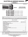
R-1380
R-1381
SUPPLEMENTAL SERVICE MANUAL
S10M141R1380E
OVER THE RANGE
MICROWAVE OVEN
MODELS
TURNTABLE
SENSOR DEFROST
BREAK FAST
POPCORN
1 Baked potatoes
2 Fresh vegetables
3 Frozen vegetables
4 Rice
5 Ground meat
6 Fish/Seafood
7 Chicken breasts
8 Turkey breast
9 Roast pork
0 Meat loaf
DINNER
2
7
4
9
3
8
CUSTOM
HELP
MINUTE
PLUS
1 Dinner plate
2 Pasta/casserole
3 Frozen entree
4 Frozen snack
5 Pizza, slice
LUNCH
1
6
HELP
OFF COOK
1 Coffee/tea
2 Roll/muffin, fresh
3 Roll/muffin, frozen
4 Hot cereal
5 Scrambled eggs
R-1380
R-1381
COMPU
DEFROST
MEMORY
COOK
5
0
POWER
LEVEL
TIMER
CLOCK
STOP
CLEAR
START
TOUCH ON
TURNTABLE
ON/OFF
WORK
LIGHT
NIGHT
LIGHT
FAN
HI/LO
In the interest of user-safety the oven should be restored to its original
condition and only parts identical to those specified should be used.
WARNING TO SERVICE PERSONNEL: Microwave ovens contain circuitry capable of producing very high voltage and
current. Contact with the following parts may result in a
severe, possibly fatal, electrical shock. (High Voltage Capacitor, High Voltage Power Transformer, Magnetron, High Voltage Rectifier Assembly, High Voltage Harness etc..)
This is a supplemental Service Manual for Microwave Oven model R-1380/R-1381. This model is quite similar to
the base model R-1480/81 (S/M# S3807R1480X//).
This supplemental manual must be used in conjunction with the base model service manual for complete operation,
service, safety and replacement parts information.
TABLE OF CONTENTS
Page
PRECAUTIONS TO BE OBSERVED BEFORE AND DURING SERVICING TO
AVOID POSSIBLE EXPOSURE TO EXCESSIVE MICROWAVE ENERGY .................. INSIDE FRONT COVER
BEFORE SERVICING ..................................................................................................... INSIDE FRONT COVER
WARNING TO SERVICE PERSONNEL .............................................................................................................. 1
MICROWAVE MEASUREMENT PROCEDURE .................................................................................................. 2
FOREWORD AND WARNING ............................................................................................................................. 3
OPERATION ........................................................................................................................................................ 4
PICTORIAL DIAGRAM ........................................................................................................................................ 5
PARTS LIST ......................................................................................................................................................... 6
PACKING AND ACCESSORIES ......................................................................................................................... 12
SHARP CORPORATION
This document has been published to be used for after
sales service only.
The contents are subject to change without notice.
R-1380
R-1381
PRECAUTIONS TO BE OBSERVED BEFORE AND
DURING SERVICING TO AVOID POSSIBLE
EXPOSURE TO EXCESSIVE MICROWAVE
ENERGY
(a) Do not operate or allow the oven to be operated with the door open.
(b) Make the following safety checks on all ovens to be serviced before activating the magnetron or other
microwave source, and make repairs as necessary: (1) interlock operation, (2) proper door closing, (3)
seal and sealing surfaces (arcing, wear, and other damage), (4) damage to or loosening of hinges and
latches, (5) evidence of dropping or abuse.
(c) Before turning on microwave power for any service test or inspection within the microwave generating
compartments, check the magnetron, wave guide or transmission line, and cavity for proper alignment,
integrity, and connections.
(d) Any defective or misadjusted components in the interlock, monitor, door seal, and microwave
generation and transmission systems shall be repaired, replaced, or adjusted by procedures described
in this manual before the oven is released to the owner.
(e) A microwave leakage check to verify compliance with the Federal Performance Standard should be
performed on each oven prior to release to the owner.
BEFORE SERVICING
Before servicing an operative unit, perform a microwave emission check as per the Microwave
Measurement Procedure outlined in this service manual.
If microwave emissions level is in excess of the specified limit, contact SHARP ELECTRONICS
CORPORATION immediately @1-800-237-4277.
If the unit operates with the door open, service person should 1) tell the user not to operate the oven
and 2) contact SHARP ELECTRONICS CORPORATION and Food and Drug Administration's
Center for Devices and Radiological Health immediately.
Service personnel should inform SHARP ELECTRONICS CORPORATION of any certified unit found
with emissions in excess of 4mW/cm2. The owner of the unit should be instructed not to use the unit
until the oven has been brought into compliance.
R-1380
R-1381
WARNING TO SERVICE PERSONNEL
Microwave ovens contain circuitry capable of producing very high voltage and current, contact with
following parts may result in a severe, possibly
fatal, electrical shock.
(Example)
High Voltage Capacitor, High Voltage Power Transformer, Magnetron, High Voltage Rectifier Assembly, High Voltage Harness etc..
Read the Service Manual carefully and follow all
instructions.
Don't Touch !
Danger High Voltage
When the testing is completed,
1. Disconnect the power supply cord, and then remove
outer case.
2. Open the door and block it open.
3. Discharge high voltage capacitor.
4. Reconnect the leads to the primary of the power
transformer.
5. Reinstall the outer case (cabinet).
6. Reconnect the power supply cord after the outer case is
installed.
7. Run the oven and check all functions.
Before Servicing
1. Disconnect the power supply cord
remove outer case.
2. Open the door and block it open.
3. Discharge high voltage capacitor.
, and then
WARNING:RISK OF ELECTRIC SHOCK.
DISCHARGE THE HIGH-VOLTAGE
CAPACITOR BEFORE SERVICING.
The high-voltage capacitor remains charged about 60
seconds after the oven has been switched off. Wait for 60
seconds and then short-circuit the connection of the highvoltage capacitor (that is the connecting lead of the highvoltage rectifier) against the chassis with the use of an
insulated screwdriver.
After repairing
1. Reconnect all leads removed from components during
testing.
2. Reinstall the outer case (cabinet).
3. Reconnect the power supply cord after the outer case is
installed.
4. Run the oven and check all functions.
Whenever troubleshooting is performed the power supply
must be disconnected. It may in, some cases, be necessary
to connect the power supply after the outer case has been
removed, in this event,
1. Disconnect the power supply cord, and then remove
outer case.
2. Open the door and block it open.
3. Discharge high voltage capacitor.
4. Disconnect the leads to the primary of the power
transformer.
5. Ensure that these leads remain isolated from other
components and oven chassis by using insulation tape.
6. After that procedure, reconnect the power supply cord.
Microwave ovens should not be run empty. To test for the
presence of microwave energy within a cavity, place a cup
of cold water on the oven turntable, close the door and set
the power to HIGH and set the microwave timer for two (2)
minutes. When the two minutes has elapsed (timer at zero)
carefully check that the water is now hot. If the water
remains cold carry out Before Servicing procedure and reexamine the connections to the component being tested.
When all service work is completed and the oven is fully
assembled, the microwave power output should be checked
and microwave leakage test should be carried out.
1
R-1380
R-1381
MICROWAVE MEASUREMENT PROCEDURE
A. Requirements:
1) Microwave leakage limit (Power density limit): The power density of microwave radiation emitted by a microwave oven
should not exceed 1mW/cm2 at any point 5cm or more from the external surface of the oven, measured prior to acquisition
by a purchaser, and thereafter (through the useful life of the oven), 5 mW/cm2 at any point 5cm or more from the external
surface of the oven.
2) Safety interlock switches Primary interlock relay and door sensing switch shall prevent microwave radiation emission
in excess of the requirement as above mentioned, secondary interlock switch shall prevent microwave radiation
emission in excess of 5 mW/cm2 at any point 5cm or more from the external surface of the oven.
B. Preparation for testing:
Before beginning the actual measurement of leakage, proceed as follows:
1) Make sure that the actual instrument is operating normally as specified in its instruction booklet.
Important:
Survey instruments that comply with the requirement for instrumentation as prescribed by the performance standard
for microwave ovens, 21 CFR 1030.10(c)(3)(i), must be used for testing.
2) Place the oven tray in the oven cavity.
3) Place the load of 275±15 ml (9.8 oz) of tap water initially at 20±5½C (68OF) in the center of the oven cavity.
The water container shall be a low form of 600 ml (20 oz) beaker with an inside diameter of approx. 8.5 cm (3-1/2 in.)
and made of an electrically nonconductive material such as glass or plastic.
The placing of this standard load in the oven is important not only to protect the oven, but also to insure that any leakage
is measured accurately.
4) Set the cooking control on Full Power Cooking Mode
5) Close the door and select a cook cycle of several minutes. If the water begins to boil before the survey is completed,
replace it with 275 ml of cool water.
C. Leakage test:
Closed-door leakage test (microwave measurement)
1) Grasp the probe of the survey instrument and hold it perpendicular to the gap between the door and the body of the oven.
2) Move the probe slowly, not faster than 1 in./sec. (2.5 cm/sec.) along the gap, watching for the maximum indication on
the meter.
3) Check for leakage at the door screen, sheet metal seams and other accessible positions where the continuity of the
metal has been breached (eg., around the switches, indicator, and vents).
While testing for leakage around the door pull the door away from the front of the oven as far as is permitted by the closed
latch assembly.
4) Measure carefully at the point of highest leakage and make sure that the highest leakage is no greater than 4mW/cm2,
and that the secondary interlock switch does turn the oven OFF before any door movement.
NOTE: After servicing, record data on service invoice and microwave leakage report.
2
R-1380
R-1381
SERVICE MANUAL
PRODUCT DESCRIPTION
OVER THE RANGE
MICROWAVE OVEN
R-1380 / R-1381
OPERATION
FOREWORD
This Manual has been prepared to provide Sharp Electronics Corp.
Service Personnel with Operation and Service Information for the
SHARP OVER THE RANGE MICROWAVE OVEN, R-1380, R-1381
It is recommended that service personnel carefully study the entire
text of this manual so that they will be qualified to render satisfactory
customer service.
Check the interlock switches and the door seal carefully. Special
attention should be given to avoid electrical shock and microwave
radiation hazard.
Note
This supplemental service manual contains updated information only.
Please refer to base model service manual (R-1480/R-1481)
for complete service information.
WARNING
Never operate the oven until the following points are ensured.
(A) The door is tightly closed.
(B) The door brackets and hinges are not defective.
(C) The door packing is not damaged.
(D) The door is not deformed or warped.
(E) There is not any other visible damage with the oven.
Servicing and repair work must be carried out only by trained service
personnel.
DANGER
Certain initial parts are intentionally not grounded and
present a risk of electrical shock only during servicing.
Service personnel - Do not contact the following parts while
the appliance is energized;
High Voltage Capacitor, Power Transformer, Magnetron,
High Voltage Rectifier Assembly, High Voltage Harness;
If provided, Vent Hood, Fan assembly, Cooling Fan Motor.
All the parts marked “*” on parts list are used at voltages more
than 250V.
Removal of the outer wrap gives access to voltage above 250V.
All the parts marked on “∆” parts list may cause undue microwave
exposure, by themselves, or when they are damaged, loosened
or removed.
SHARP ELECTRONICS CORPORATION
SHARP PLAZA, MAHWAH,
NEW JERSEY 07430-2135
3
WIRING DIAGRAM
PARTS LIST
R-1380
R-1381
MAGNETRON
TEMPERATURE FUSE
CONTROL UNIT
COM.
N.O.
RY4
HOOD FAN
THERMAL
CUT OUT
RY5
High
B3
N.C.
GRN
B1
Low
E2
HOOD
CAPACITOR
A3
B9
A7
N.O.
TTM
HOOD
LAMP
HL
A5
HL
FAN
MOTOR
A1
TURNTABLE
MOTOR
HOOD
MOTOR
RY1
FM
DOOR
SENSING
SWITCH
RY2
HIGH VOLTAGE
CAPACITOR
0.94µF
COM.
OL
STIRRER
MOTOR
RY3
OVEN LAMP
120 V AC. GND
60 Hz
WHT
POWER
TRANSFORMER
E1
SSR
BLK
B5
MONITOR
SWITCH
B7
PRIMARY
INTERLOCK
RELAY
FUSE
20A
STM
MAGNETRON
CAVITY
THERMAL CUT-OUT
SCHEMATIC
NOTE: CONDITION OF OVEN
1. DOOR CLOSED
2. CLOCK APPEARS ON DISPLAY
HIGH VOLTAGE
RECTIFIER
SECONDARY
INTERLOCK
SWITCH
Figure O-1. Oven Schematic-Off Condition
SCHEMATIC
NOTE: CONDITION OF OVEN
1. DOOR CLOSED
2. COOKING TIME PROGRAMMED
3. VARIABLE COOKING CONTROL "HIGH"
4. "START" PAD TOUCHED
CAVITY
THERMAL CUT-OUT
MAGNETRON
TEMPERATURE FUSE
CONTROL UNIT
COM.
N.O.
RY4
RY5
B3
E1
N.C.
GRN
B1
Low
E2
HOOD
CAPACITOR
A1
A3
B9
A5
N.O.
TTM
HOOD
LAMP
HL
A7
HL
FAN
MOTOR
HOOD
MOTOR
RY1
FM
DOOR
SENSING
SWITCH
RY2
HIGH VOLTAGE
CAPACITOR
0.94µF
COM.
OL
STIRRER
MOTOR
RY3
OVEN LAMP
120 V AC. GND
60 Hz
WHT
POWER
TRANSFORMER
STM
SECONDARY
INTERLOCK
SWITCH
Figure O-2. Oven Schematic-Cooking Condition
4
HIGH VOLTAGE
RECTIFIER
MAGNETRON
High
TURNTABLE
MOTOR
HOOD FAN
THERMAL
CUT OUT
SSR
BLK
B5
MONITOR
SWITCH
B7
PRIMARY
INTERLOCK
RELAY
FUSE
20A
A
B
C
D
E
F
G
H
HOOD FAN MOTOR
6
GRN
to Chassis Support
GRN
CN-E
BLK
WHT 2 WHT
GRN 1 GRN
2 GRN
1 RED
N.O.
CAVITY
THERMAL
CUT-OUT
9
ORG
8
7
RED
CN-F
3
1
RY4
MAGNETRON
TEMPERATURE
FUSE
BLK
RED
CN-A
7
FUSE & HOLDER
WHT
6
5
N.O.
RED
BLK
1 WHT
RY5
RY1
N.O.
COM.
WHT
RED
2
RY2: PRIMARY
INTERLOCK
RELAY
T1
WHT
G
R
Y
3
3
CN-B
9
WHT
ORG
5
4
3
1
2
CN-E
RED
BLU
WHT
6
RY2
OVEN LAMP & SOCKET
2
2
CN-E
1
RED
CN-B
IC1
12
BLK
RED
STIRRER MOTOR
IC1
CN-G
1
ORG
WHT
DOOR SENSING SWITCH
CONTROL UNIT
Power Supply
cord 120V 60Hz
Blue
Marking
RED
GRN
COM.
3 BLK
1
1
RED 5 RED
YLW 4 YLW
WHT 3 WHT
BLK 2 BLK
BLU 1 BLU
COM.
CN-A
75
C100
5
4
3
HIGH VOLTAGE COMPONENTS
BLK
BLK
MAGNETRON
YLW
2
31
HIGH VOLTAGE
CAPACITOR
1 RED
RY1
COM.
RY2
N.O.
HIGH VOLTAGE
WIRE A
RED
ORG
WHT
RED
WHT
WHT
BLK
BLK
N.C.
FAN
MOTOR
WHT
COM.
RED
POWER
TRANSFORMER
MONITOR
SWITCH
ORG
W W
H H
T T
ORG
N.O.
to Right Base Plate
SECONDARY
INTERLOCK
SWITCH
R
E
D
WHT
RED
WHT
COM.
HIGH
VOLTAGE
RECTIFIER
5
5
RY2
COM.
RED
4
4
RY1
N.O.
GRY
WHT
GRY
WHT
WHT
ORG
BLK
RED
GRY
ORG
Blue Marking
ORG
HOOD FAN
THERMAL
CUT-OUT
A
B
C
D
E
F
G
H
R-1380
R-1381
Figure S-1. Pictorial Diagram
6
6
TURNTABLE
MOTOR
ORG
HOOD LAMPS
& SOCKETS
R-1380
R-1381
PARTS LIST
Note: The parts marked “∆” may cause undue microwave exposure.
The parts marked “*” are used in voltage more than 250V.
REF. NO.
PART NO.
§
"§" MARK: PARTS DELIVERY SECTION
DESCRIPTION
Q'TY CODE
ELECTRIC PARTS
*
*
*
∆*
1- 1
1- 2
1- 3
1- 4
1- 5
1- 6
1- 7
1- 8
1- 9
1-10
1-11
1-12
1-13
1-14
1-15
1-16
1-17
FH-DZB012MRY0
RC-QZA234WRE0
QFS-TA013WRE0
RMOTDA211WRE0
RMOTDA214WRE0
RTHM-0044MRE0
RTRN-B062MRE0
RV-MZA281WRE0
QFSHDB003MRE0
QSW-MA110WRE0
FFS-BA016/KIT
FACCDB011MRE0
QSOCLB006MRE0
FMOTEA402WRK0
RMOTEA346WRE0
RLMPTA068WRE0
RTHM-A070WRE0
M
M
M
M
M
M
M
M
M
M
M
M
M
M
M
M
M
High voltage rectifier assembly
High voltage capacitor
Temperature fuse 150OC (Magnetron)
Turntable motor
Stirrer motor
Thermal cut-out N.O. 60OC (Hood Fan)
Power transformer
Magnetron
Fuse holder
Secondary interlock and door sensing switches
Monitor switch with fuse assembly
Power supply cord
Oven lamp socket
Hood fan motor
Fan motor
Oven lamp
Thermal cut-out 145OC (Cavity)
2- 1
2- 2
2- 2
2- 3
2- 4
2- 5
2- 5
2- 6
2- 7
2- 7
2-7-1
2-7-1
2-7-2
2- 8
2- 8
LSTY-B021MRP0
PDIF-B018MRF0
PDIF-B019MRF0
GDAI-B058MRP0
PCUSUB040MRP0
GCABUB084MRP0
GCABUB090MRP0
TMAPCB052MRR0
FANGKB009MRY0
FANGKB010MRY0
LANGQB016MRP0
LANGQB020MRP0
PGLSPB004MRE0
PCOVPB064MRT0
PCOVPB066MRT0
M
M
M
M
M
M
M
M
M
M
M
M
M
M
M
Rear stay
Hood exhaust louver [R-1380]
Hood exhaust louver [R-1381]
Right base plate
Base cover cushion
Outer case cabinet [R-1380]
Outer case cabinet [R-1381]
Schematic diagram
Hood lamp glass assembly [R-1380]
Hood lamp glass assembly [R-1381]
Hood lamp glass angle [R-1380]
Hood lamp glass angle [R-1381]
Hood lamp glass
Base cover [R-1380]
Base cover [R-1381]
1
1
1
1
1
1
1
1
1
2
1
1
3
1
1
3
1
AK
AP
AG
AL
AQ
1
1
1
1
1
1
1
1
1
1
1
1
1
1
1
AF
AT
AT
AM
AA
BA
BC
AB
AN
AM
AG
AG
AH
AY
AY
1
1
1
1
1
1
1
1
1
1
1
1
1
1
1
1
4
1
1
1
4
1
4
2
7
1
1
1
1
BL
AA
AA
AB
AE
AS
AB
AB
AF
AH
AB
AH
AB
AB
AM
AH
AA
AK
AC
AD
AB
AA
AA
AA
AA
AW
AB
AA
AB
BF
BC
AD
AE
AF
AP
AE
BE
AR
AE
AG
CABINET PARTS
CONTROL PANEL PARTS
3- 1
3- 1A
3- 1B
3- 1C
3- 1C
3- 1E
3- 1F
C1
C2
C5
C6
C7-8
C9-10
C20
C21
C30
C70-73
C100
C110
CF1
D1-4
D20
D25-28
D30-31
D71-77
IC1
Q3
Q4
Q20
DPWBFB081MRU0
QCNCMA447DRE0
QCNCMA448DRE0
QCNCMA275DRE0
QCNCWA030DRE0
RV-KXB004MRE0
PTPEHB010MRE0
RC-KZA087DRE0
VCEAB31VW108M
VCKYD11CY103N
VCEAB31VW106M
VCKYD11CY103N
RC-KZA087DRE0
VCEAB31VW106M
VCEAB31HW104M
VCKYD11CY103N
VCKYD11HB331K
RC-QZB014MRE0
RC-QZB019MRE0
RCRS-A010DRE0
VHD11ES1///-1
VHD1SS270A/-1
VHD1SS270A/-1
VHD1SS270A/-1
VHD1SS270A/-1
RH-IZA876DRE0
VSKRA101M//-3
VSDTA123ES/-3
VSKRA101M//-3
M
M
M
J
J
M
M
J
J
J
J
J
J
J
J
J
J
M
M
M
J
J
J
J
J
J
J
J
J
Control unit
4-pin connector CN-A
5-pin connector CN-B
2-pin connector CN-E
12-pin connector CN-G
Fluorescent display tube
Tape 2mm
Capacitor
0.1 uF
50V
Capacitor
1000 uF
35V
Capacitor
0.01 uF
16V
Capacitor
10 uF
35V
Capacitor
0.01 uF
16V
Capacitor
0.1 uF
50V
Capacitor
10 uF
35V
Capacitor
0.1 uF
50V
Capacitor
0.01 uF
16V
Capacitor
0.01 uF
16V
Capacitor
7 uF
230V
Capacitor
330 pF
50V
Ceramic resonator (CST4.00MGW)
Diode (11ES1)
Diode (1SS270A)
Diode (1SS270A)
Diode (1SS270A)
Diode (1SS270A)
LSI
Transistor (KRA101M)
Transistor (DTA123ES)
Transistor (KRA101M)
6
R-1380
R-1381
REF. NO.
Q24-26
Q27
Q28
Q30
R1
R2
R3
R4
R7-8
R10
R20
R30
R31
R40
R70-73
R77-83
R91-93
R110
RY1-2
RY3-4
RY5
SSR1
SP40
T1
VRS1
ZD1
ZD3
ZD4
3- 2
3- 2
3- 2-1
3- 2-1
3- 2-2
3- 3
PART NO.
VSKRA101M//-3
VSKRC243M//-3
VSKRA101M//-3
VSKRA101M//-3
VRD-B12HF432J
VRD-B12EF152J
VRS-B13AA751J
VRD-B12HF511J
VRD-B12EF472J
VRD-B12HF3R3J
VRD-B12HF102J
VRD-B12EF153J
VRD-B12EF472J
VRD-B12EF332J
VRD-B12EF332J
VRD-B12EF332J
VRD-B12EF104J
VRS-A12HA470J
RRLY-A113DRE0
RRLY-A080DRE0
RRLY-A112DRE0
RH-SZA009DRE0
RALM-A014DRE0
RTRNPB014MRE0
RH-VZA032DRE0
VHEHZ6A3///-1
VHEHZ5C2///-1
VHEHZ4A2///-1
FPNLCB205MRK0
FPNLCB211MRK0
FUNTKB153MRE0
FUNTKB159MRE0
GMADIB030MRF0
XEPSD30P10XS0
§
J
J
J
J
J
J
J
J
J
J
J
J
J
J
J
J
J
J
M
M
M
M
J
M
J
J
J
J
M
M
M
M
M
M
DESCRIPTION
Transistor (KRA101M)
Transistor (KRC243M)
Transistor (KRA101M)
Transistor (KRA101M)
Resistor
4.3k ohm
1/2W
Resistor
1.5k ohm
1/4W
Resistor
750 ohm
1W
Resistor
510 ohm
1/2W
Resistor
4.7K ohm
1/4W
Resistor
3.3 ohm
1/2W
Resistor
1k ohm
1/2W
Resistor
15k ohm
1/4W
Resistor
4.7k ohm
1/4W
Resistor
3.3k ohm 1/4W
Resistor
3.3k ohm 1/4W
Resistor
3.3k ohm 1/4W
Resistor
100K ohm
1/4W
Resistor
47 ohm
1/2W
Relay (DU24D1-1PR(M))
Relay (OJ-SH-124LM)
Relay (VE24HSE-K)
Solid state relay
Buzzer (PKM22EPT)
Transformer
Varistor (10G471K)
Zener diod (HZ6A-3)
Zener diod (HZ5C-2)
Zener diod (HZ4A-2)
Control panel sub. assembly [R-1380]
Control panel sub, assembly [R-1381]
Key unit [R-1380]
Key unit [R-1381]
Display window
Screw; 3mm x 10mm
4- 1
4- 2
4- 3
4- 4
4- 5
4- 6
4- 7
4- 8
4- 9
4-10
4-11
4-12
4-13
4-14
4-15
4-16
4-17
4-18
4-19
4-20
4-21
4-22
FFTA-B003MRK0
FROLPB025MRK0
NTNT-A090WRE0
LANGKB010MRP0
FCOVPB016MRK0
FFAN-B009MRK0
*************
PPACGB014MRF0
PHOK-B017MRF0
LANGTB036MRP0
NFANPB001MRE0
LBSHC0037WRE0
PCOVPB065MRP0
PDUC-B084MRP0
PCUSUB039MRP0
PFILWB005MRP0
PSKR-B012MRP0
LANGTB046MRP0
LANGTB040MRP0
PDUC-B078MRF0
PCUSUB043MRP0
LSTPPB031MRF0
M
M
M
M
M
M
M
M
M
M
M
M
M
M
M
M
M
M
M
M
M
M
Exhaust damper assembly
Turntable support assembly
Turntable tray
Capacitor holder
Stirrer cover assembly
Stirrer fan assembly
Oven cavity (Not replaceable part)
Turntable motor packing
Latch hook
Unit mounting plate
Fan blade
Cord bushing
Oven lamp cover
Hood intake duct R
Hood intake duct cushion
Lamp filter
Magnetron air guide
Chassis support left
Chassis support right
Hood duct
Hood duct cushion
Door stopper
5
5
5-1
5- 2
5- 2
5-2-1
5-2-1
5-2-2
5-2-3
5-2-4
5- 3
5- 4
CDORFB245MRK0
CDORFB246MRK0
FDORFB060MRT0
FCOV-B125MRK0
FCOV-B127MRK0
PGLSPB012MRE0
PGLSPB014MRR0
LSTPPB030MRF0
LSTPPB032MRF0
MSPRTA046WRE0
FCOVHB005MRK0
PSHEPB024MRE0
M
M
M
M
M
M
M
M
M
M
M
M
Door assembly [R-1380]
Door assembly [R-1381]
Door panel assembly
Door frame assembly [R-1380]
Door frame assembly [R-1381]
Front door glass [R-1380]
Front door glass [R-1381]
Latch head
Glass stopper
Latch spring
Choke cover assembly
Sealer film
Q'TY CODE
3
AB
1
AB
1
AB
1
AB
1
AH
1
AA
2
AB
1
AA
1
AB
1
AB
1
AA
1
AA
1
AA
1
AA
4
AA
7
AA
3
AA
1
AH
2
AG
2
AG
1
AH
1
AG
1
AG
1
AM
1
AE
1
AC
1
AA
1
AA
1
AZ
1
AZ
1
AU
1
AU
1
AF
5
AB
OVEN PARTS
∆
∆
1
1
1
1
1
1
1
1
1
1
1
1
1
1
2
1
1
1
1
1
1
1
AH
AN
AN
BB
AN
AH
-AA
AG
AP
AC
AB
AD
AM
AA
AB
AB
AD
AE
AX
AE
AC
1
1
1
1
1
1
1
1
1
1
1
1
AX
AS
AS
AQ
AQ
AC
AC
AB
AG
AF
DOOR PARTS
∆
∆
∆
∆
∆
∆
∆
∆
7
R-1380
R-1381
REF. NO.
5- 5
5- 5
5- 6
PART NO.
JHNDPB007MRF0
JHNDPB008MRF0
XCPSD40P08000
§
M
M
M
DESCRIPTION
Door handle assembly [R-1380]
Door handle assembly [R-1381]
Screw : 4mm x 8mm
6- 1
6-1-1
6-1-2
6-1-3
6-1-4
6-1-5
6-1-6
6-1-7
6- 2
6- 3
6- 4
6- 5
6- 6
6- 7
6- 8
6- 9
6-10
6-11
6-12
6-13
6-14
CFZK-B131MRK0
LBSHC0040MRE0
LX-BZ0195WRE0
LX-MZB001MRE0
XBRSD50P60000
XOTSD40P12000
XTSSD50P35000
XWHSD50-16300
TINSEB227MRR0
TINSEB223MRR0
TINSKB047MRR0
TINSKB048MRR0
QW-QZB023MRE0
FW-VZB145MRE0
TCAUAA025WRR0
TCAUAB037MRR0
TCAUAB005MRR0
FW-VZB149MRE0
PFIL-B004MRE0
PFIL-B002MRE0
PCLICB003MRE0
M
M
M
M
M
M
M
M
M
M
M
M
M
M
M
M
M
M
M
M
M
Installation material assembly
Grommet
Toggle screw
Cord holder
Screw : 5mm x 60mm
Screw : 4mm x 12mm
Screw : 5mm x 35mm
Washer
Installation instruction
Operation manual
Top template
Wall template
High voltage wire A
Main harness
A
Caution label
Monitor caution label
DHHS caution label
Stop switch harness
Charcoal filter
Grease filter
Canoe clip
Q'TY CODE
1
AK
1
AK
6
AA
MISCELLANEOUS
*
1
1
4
1
2
1
6
2
1
1
1
1
1
1
2
1
1
1
1
2
1
AM
AC
AC
AB
AC
AA
AA
AA
AB
AD
AC
AB
AD
AU
AA
AA
AB
AM
AH
AF
AA
2
4
4
13
2
4
2
5
2
4
AA
AB
AA
AA
AA
AA
AA
AA
AA
AD
SCREWS,NUTS AND WASHERS
7777777777-
1
2
2
3
4
5
6
7
8
9
XCPSD40P08000
XOTSF40P12000
XOTSE40P12000
XOTSD40P12000
XBTSD40P08000
LX-CZA038WRE0
LX-CZ0052WRE0
LX-BZ0081YBE0
XCPSD30P08000
LX-BZB012MRE0
M
M
M
M
M
M
M
M
M
M
Screw : 4mm x
Screw : 4mm x
Screw : 4mm x
Screw : 4mm x
Screw : 4mm x
Special screw
Special screw
Screw : 4mm x
Screw : 4mm x
Unit mounting
8mm
12mm [R-1380]
12mm [R-1381]
12mm
8mm
8mm
8mm
screw
HOW TO ORDER REPLACEMENT PARTS
To have your order filled promptly and correctly, please furnish the following information.
1. MODEL NUMBER
2. REF. NO.
3. PART NO.
4. DESCRIPTION
Order Parts from the authorized SHARP parts Distributor for your area.
Defective parts requiring return should be returned as indicated in the Service Policy.
8
R-1380
R-1381
2
1
4
3
6
5
OVEN AND CABINET PARTS
7-3
A
A
4-1
7-3
1-14
4-13
2-1
7-5
4-20
7-3
4-10
B
B
2-5
7-3
4-12
4-11
7-4
1-12
2-6
C
7-5
1-15
7-1
C
1-16
1-13
1-17
4-18
7-8
1-5
7-3
1-3
6-10
D
D
7-9
4-7
4-19
E
E
4-21
6-12
7-3
6-9
7-6
1-10
1-9
1-8
2-2
4-6
7-7
7-9
4-14
1-2
F
4-17
6-8
4-16
7-7
6-8
4-8
4-5
1-4
6-13
7-8
4-3
6-14
1-11
4-9
1-10
4-4
F
7-8
1-7
7-8
1-1
1-6
4-15
2-3
2-8
G
G
7-3
2-4
4-2
7-3
1-13
7-3
6-13
2-7-2
1-16
H
H
2-7
7-2
2-7-1
7-2
1
2
4
3
9
5
6
R-1380
R-1381
2
1
4
3
6
5
CONTROL PANEL PARTS
3-3
3-2
3-2-2
A
A
3-1E
7-3
3-1
3-3
B
B
DOOR PARTS
3-3
3-2-1
4-22
5-4
5-6
C
C
5-3
5-1
5-2
5-6
5-3
5-2-1
D
D
5-6
5-2-3
E
E
5-2-2
5-2-4
5-5
MISCELLANEOUS
F
F
6-6
6-7
G
G
6-1
6-1-1
6-1-4
6-1-5
6-1-2
6-1-3
6-1-6
6-1-7
6-11
H
1
2
4
3
10
H
5
6
R-1380
R-1381
PACKING AND ACCESSORIES
TOP PAD
DOOR PROTECTOR
WRAP COVER
4-3 TURNTABLE TRAY
RACK HOLDER
6-1
INSTALL MATERIAL ASSEMBLY
DOOR PAD
6-3 OPERATION MANUAL
6-5 WALL TEMPLATE
6-2 INSTALLATION INSTRUCTION
6-4 TOP TEMPLATE
BOTTOM PAD
6-13 GREASE FILTER (x 2)
ACCESSORY HOLDER
PACKING CASE
Non-replaceable items
11
R-1380
R-1381
COPYRIGHT © 1999 BY SHARP CORPORATION
ALL RIGHTS RESERVED.
No part of this publication may be reproduced, stored in retrieval systems, or transmitted in any form or by any means, electronic, mechanical, photocopying, recording, or otherwise, without prior written permission of the publisher.
'2000 SHARP CORP. (2S2.530E) Printed in U.S.A
12