1
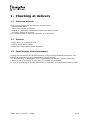
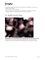
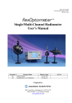
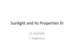
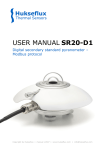
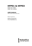
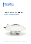
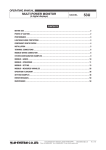
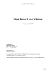
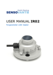
DR01
First class pyrheliometer
DR02
Fast response first class pyrheliometer
USER MANUAL
DR01 DR02 manual v1225
Warning
Warnings and safety issues:
DR01 and DR02 are passive sensors, and do
not need any power. Window heating
however does require 12 VDC for heating at
0.5 Watt.
Putting more than 12 Volt across DR01 or
DR02 sensor wiring can lead to permanent
damage to the sensor.
DR02 should not be used in combination
with datalogging with open circuit detection.
D R 01 D R 0 2 man u al v12 25
2/ 19
Contents
Warning
Contents
List of symbols
Introduction
Checking at delivery
1.
Presence of parts
1.1
Options
1.2
Functionality of the instrument
1.3
Instrument principle
2.
Specifications of DR01 / DR02
3.
Installation
4.
Installation
4.1
Electrical connection
4.2
Dimensions
5.
Maintenance and troubleshooting
6.
Maintenance
6.1
Testing and troubleshooting
6.2
Requirements for data acquisition / amplification
7.
Appendices
8.
Appendix on cable extension / replacement
8.1
Appendix on calibration
8.2
Appendix on sensor coating
8.3
Declaration of conformity CE
8.4
D R 01 D R 0 2 man u al v12 25
2
3
4
5
6
6
6
6
7
8
10
10
10
12
13
13
13
15
16
16
16
17
18
3/ 19
List of symbols
Voltage output
Sensitivity of DR01 / DR02
Solar irradiance
D R 01 D R 0 2 man u al v12 25
U
E
Φ
μV
μV/(W/m2)
W/m2
4/ 19
Introduction
DR01 and DR02 are research grade direct normal incidence (DNI) solar irradiance
sensors, also known as pyrheliometers. They comply with ‘First Class’ classification, as
per the latest ISO 9060 standard and ‘Good Quality’ from WMO. A unique product feature
is the heated window. DR01 and DR02 are typically mounted on a solar tracker.
DR02 is the fast-response equivalent of DR01. The only difference is in detector
technology, resulting in a much faster response time (95 %) for DR02: 2 s instead of
traditional 18 s. DR02 offers a wider measurement range (0 to 4000 W/m2) and the
possibility to improve the temperature response as well.
In this manual, DR01 is the pyrheliometer mentioned; DR02 wil be mentioned only in
case this is necessary. DR01 window assembly features a precision ground and polished
quartz window, for true spectral solar transmission ranging from 0.2 to 4.0 x 10⁻⁶ m. As
per the latest ISO 9060 and WMO standards, the full opening view angle of the DR01 is
collimated precisely to 5 degrees, for direct normal incidence solar irradiance
measurement.
Capable of measuring up to 2000 W/m2 (DR02: up to 4000 W/m2), the DR01
pyrheliometer can be deployed anywhere on earth. The instrument employs a passive
thermopile-based sensing technology that generates a low level DC millivolt output signal
proportional to the normal incident direct solar flux received at the detector surface. The
DR01 also features a thermally isolated low power window heater in the window; when
cycled on/off prior to sunrise the heater effectively eliminates the formation of dew on
the pyrheliometer window. This results in improved post sunrise measurement accuracy,
as well as lower maintenance, as it requires less cleaning.
Determining direct solar irradiance with the DR01 requires connection to a data
acquisition and a two-axis solar tracker platform. Typical pyrheliometer measurement
applications include solar renewable resource assessment, concentrated PV electricity
output validation, solar collector and PV panel efficiency validation, material testing
research.
Each DR01 is calibrated upon manufacture and delivered standard with a WRR (World
Radiometric Reference) traceable certificate of calibration.
Options include: extended cable lengths, AC100 / AC420 amplifiers, temperature sensors
(Pt100 or 10 kOhm thermistor) and temperature dependence characterisation.
Various tracking solutions can be offered by Hukseflux.
Figure 0.1 DR01 first class pyrheliometer
D R 01 D R 0 2 man u al v12 25
5/ 19
1. Checking at delivery
1.1
Presence of parts
Arriving at the customer, the delivery should include:
- pyrheliometer DR01
- cable of the length as ordered
- calibration certificate matching the instrument serial number
- any other options as ordered
It is recommended to store the certificate in a safe place.
1.2
Options
-longer cable, in multiples of 5 m
-internal temperature sensor
-temperature dependence characterisation
1.3
Functionality of the instrument
Testing the instrument can be performed by using a simple handheld multimeter. See
Chapter 6.2 on testing and troubleshooting on this subject.
The programming of dataloggers is the responsibility of the user. Please contact the
supplier to see if directions for use with your system are available.
In case programming for similar instruments is available, this can typically also be used.
D R 01 D R 0 2 man u al v12 25
6/ 19
2. Instrument principle
2
2
4
3
1
5
7
6
Figure 2.1 DR01 pyrheliometer; (1) humidity indicator, (2) sights, (3) aperture tube,
(4) protection cap, (5) window with heater, (6) cable gland, (7) cable
DR01’s scientific name is pyrheliometer. A pyrheliometer measures the solar radiation
flux with a field of view of 5 degrees.
The solar radiation spectrum extends roughly from 300 to 2800 x 10-9 m. It follows that
a pyrheliometer should cover that spectrum with a spectral sensitivity that is as “flat” as
possible.
For a correct measurement the DR01 should be pointed at the sun. In order to attain the
proper spectral characteristics, a pyrheliometer’s main components are:
1 a thermopile sensor with a black coating. This sensor absorbs all solar radiation, has a
flat spectrum from visible light to infra-red and has a near-perfect cosine response.
2 a quartz window. This window limits the spectral response from 200 to 4000 x 10-9 m
(cutting off the part above 4000 x 10-9 m). Another function of the window is that it
shields the thermopile sensor from convection.
The black coating on the thermopile sensor absorbs the solar radiation. This radiation is
converted to heat, which flows through the sensor to the DR01 housing. The thermopile
sensor generates a voltage output signal that is proportional to the solar radiation.
D R 01 D R 0 2 man u al v12 25
7/ 19
3. Specifications of DR01 / DR02
DR01 serves to measure the solar radiation flux that is incident on a plane surface in
W/m2 from a 5 degrees field of view (also called direct normal incidence radiation).
Working completely passive, using a thermopile sensor, DR01 generates a small output
voltage proportional to this flux. The front window contains a heater that can be put on
at nighttime to prevent dew deposition. It can only be used in combination with a
suitable measurement system and tracker. DR02 is a fast-response version of DR01.
Table 3.1 Specifications of DR01 and DR02
DR01 and DR02 ISO Specifications
1
Measurand
Direct solar radiation
2
ISO classification
First class pyrheliometer
3
Response time (time for 95 % response)
DR01: 18 s
DR02: 2 s
4
Zero offset (response to 5 K/h change in
ambient temperature)
< ± 1 W/m2
5
Non-stability (percentage change in
responsivity per year)
<±1%
6
Non-Linearity ( percentage deviation from < ± 0.3 %
responsivity at 500 W/m2 due to change in
irradiance within 100-1000 W/m2)
7
Spectral selectivity (percentage deviation
of the product of spectral absorptance and
spectral transmittance from the
corresponding mean within 0.35 µm and
1.5 µm)
<±1%
8
Temperature response ( percentage
deviation due to change in ambient
temperature within an interval of 50 K)
DR01: < ± 1 %
9
(-10 to +40 °C)
DR02: < ± 1 % (-10 to +40 °C)
DR02: < ± 0.4 % (-30 to +50 °C) with
correction in data processing, if opted for
internal temperature sensor and
temperature dependence characterisation
(see options)
Tilt response (percentage deviation from
< ± 0.5 %
the responsivity at 0 ° tilt (horizontal) due
to change in tilt from 0-90 ° at 1000 W/m2
irradiance)
DR01 and DR02 additional measurement specifications
10
Full field of view angle
5
°
11
Slope angle
1
°
12
Sensitivity (nominal)
10 x 10-6 V/(W/m2)
13
Expected voltage output
Application with natural solar radiation:
-0.1 to +30 x 10-3 V
D R 01 D R 0 2 man u al v12 25
8/ 19
14
Rated operating temperature range
-40 to +80 °C
15
Sensor resistance
DR01: between 400 and 500 Ohm
DR02: between 150 and 250 Ohm
16
Power required
Zero (passive sensor), see also heater
17
Measurement range
DR01: to 2000 W/m2
DR02: to 4000 W/m2
18
Expected accuracy for daily sums
±2%
19
Spectral range (50 % transmission points) 200 to 4000 x 10-9 m
(the spectral responsivity of field
pyrheliometers is limited to the range
approximately 0.3 µm to 3 µm, depending
on the spectral transmittance of the
window which protects the receiver
surface)
20
Drying cartridge/ humidity indicator
Bag of silica gel, 0.5 g, 35 x 20 mm
Humidity indicator B2
21
Required readout:
1 differential voltage channel or
1 single ended voltage channel
22
Programming
Φ=U/E
23
Heater
Heating front window: 0.5 Watt @ 12 VDC,
typically activated during nighttime only to
prevent dew deposition
24
Standard cable length / diameter
5 m / 5 mm (see options)
25
Cable gland
Accepts cable diameter from 3 to 6.5 mm
26
Cable replacement
Cable can be replaced by the user
27
Weight including 5 m cable, size
1.4 kg
box of 43 x 11 x 11 cm
28
Tracking
Not included, preferably within 1 degree
Calibration
29
Calibration uncertainty
< 1.3 % (k = 2)
30
Calibration traceability
To WRR, procedure according to ISO 9059
31
Recommended recalibration interval
Every 2 years (sensitivity)
Options
32
Cable extension
Longer cables can be supplied on request.
Specify multiple of 5 m
33
Amplifiers
AC100 and AC420
34
Temperature dependence characterisation
35
Temperature sensor
Pt100 or 10K thermistor can be added
DR01-T1 includes a Pt100
DR01-T2 includes a 10K thermistor
DR02-T1 includes a Pt100
DR02-T2 includes a 10K thermistor
DR01 and DR02 also comply with WMO specifications
D R 01 D R 0 2 man u al v12 25
9/ 19
4. Installation
4.1
Installation
DR01 is to be installed on a tracker, with an accuracy of 1 degree form true solar
position. The mounting should be done by clamping around the DR01 tube (1.5 inch or
38 mm).
4.2
Electrical connection
In order to operate, DR01 should be connected to a measurement system, or datalogger.
DR01 is a passive sensor that does not need any power.
DR02 should not be used in combination with datalogging with open circuit detection.
Cables generally act as a source of distortion, by picking up capacitive noise. It is a
general recommendation to keep the distance between data logger or amplifier and
sensor as short as possible. For cable extension, see the appendix on this subject.
Table 4.2.1 The electrical connection of DR01. Heater polarity is not important.
PCB connection
Description
Wire colour
8
Thermopile [+]
White
7
Thermopile [-]
Green
1
Temperature sensor [+] (if present)
Red
2
Temperature sensor [+] (if present)
Brown
3
Temperature sensor [-] (if present)
Yellow
4
Temperature sensor [-] (if present)
Blue
5
Heater 12VDC [+]
Pink
6
Heater 12VDC [-]
Grey
Ground
Ground
Black
D R 01 D R 0 2 man u al v12 25
10/19
Figure 4.2.1 Electrical diagram of DR01 thermopile detector. The heater is a simple
resistor on a separate cable.Temperature sensor is only present if ordered.
D R 01 D R 0 2 man u al v12 25
11/19
5. Dimensions
380
Ø 38
50
215
Figure 5.1 Dimensions of DR01 in mm. Tube diameter is 38 mm, approximately 1.5
inch.
D R 01 D R 0 2 man u al v12 25
12/19
6. Maintenance and troubleshooting
6.1
Maintenance
Once installed DR01 is essentially maintenance free.
Periodically dessicant may be replaced.
Usually errors in functionality will appear as unreasonably large or unreasonably small
measured values.
As a general rule, this means that a critical review of the measured data is the best form
of maintenance.
Recommendations for maintenance are:
1. Critical review of data
2. Cleaning of window by water or alcohol
3. Inspection of interior of window; no condensation
4. Dessicant inspection: change in case the humidity indicator has turned pink.
Regeneration is possible by heating more than 3 hours at 120 °C. Spanner size
required for removal of dessicant is 20.
5. Pointing inspection: daily inspection against sight of the instrument.
6. Inspection of cables for open connections
7. Recalibration: suggested every 2 years, typically by intercomparison with a higher
standard in the field.
6.2
Testing and troubleshooting
This paragraph contains information that can be used for testing of the instrument and to
make a diagnosis whenever the sensor does not function.
1. Check the impedance of the sensor between the green (-) and white (+) wire. Use
a multimeter at the 1000 ohms range. (500 ohms for DR02).
Measure the impedance at the sensor wires, first with one polarity, than reverse
polarity. Take the average value. The typical impedance of the wiring is 0.1
ohm/m. Typical impedance should be the typical sensor impedance of DR01 (400500 ohms) or DR02 (150-250 ohms) plus 1 ohm for the total resistance of two
wires (back and forth) of each 5 meters. Infinite indicates a broken circuit; zero
indicates a short circuit
2. Check if the sensor reacts to light: put the multimeter at its most sensitive range
of DC voltage measurement, typically 100 microvolt range or lower and expose
the sensor to a strong light source, for instance a 100 Watt light bulb at 10
centimeter distance. The signal should read several millivolts now
3. Darken the sensor either by putting something over it or switching off the light.
The instrument voltage output should go down and within one minute approach
zero mV
4. Check if the right calibration factor is entered into the algorithm. Please note that
each sensor has its own individual calibration factor
5. Check if the voltage reading is divided by the calibration factor by review of the
algorithm
6. Check the condition of the leads at the logger
7. Check the cabling condition looking for cable breaks
D R 01 D R 0 2 man u al v12 25
13/19
8. Check the range of the data logger; heat flux can be negative (this could be out of
range) or the amplitude could be out of range
9. Check the data acquisition by applying a mV source to it in the 1 mV range
10. Check the presence of strong sources of electromagnetic radiation (radar, radio
etc.)
11. Check the condition of the shielding
12. Check the condition of the sensor cable
D R 01 D R 0 2 man u al v12 25
14/19
7. Requirements for data acquisition /
amplification
Table 7.1 Requirements for data acquisition and amplification equipment.
1
Capability to measure microvolt Preferably: 5 microvolt accuracy
signals
Minimum requirement: 20 microvolt accuracy
(both across the entire expected temperature range of
the acquisition / amplification equipment)
2
Capability for the datalogger or
the software
To store data, and to perform division by the sensitivity
to calculate the solar irradiance
3
Heating power
Heating is not a necessity.
When used: 0.5 W at 12 VDC
4
Warning
DR02 should not be used in combination with
datalogging with open circuit detection.
D R 01 D R 0 2 man u al v12 25
15/19
8. Appendices
8.1
Appendix on cable extension / replacement
DR01 is equipped with one cable for the detector and heater. It is a general
recommendation to keep the distance between datalogger or amplifier and sensor as
short as possible. Cables generally act as a source of distortion, by picking up capacitive
noise. DR01 signal cable can however be extended without any problem to 100 meters.
If done properly, the sensor signal, although small, will not significantly degrade because
the sensor impedance is very low.
Cable and connection specifications are summarised below.
NOTE: the body of DR01 contains connector blocks that can be used for internal
connection of a new cable. Usually it is easier to connect a new longer cable than to
extend an existing cable.
Table 8.1.1 Specifications for cable extension
1
Cable
8-wire shielded, copper core
2
Core resistance
0.1 Ω/m or lower
3
Outer diameter
(preferred) 5 mm
4
Outer sheet
(preferred) polyurethane (for good stability in
outdoor applications).
5
Connection
Either solder the new cable core and shield to the
original sensor cable, and make a waterproof
connection using cable shrink, or use gold plated
waterproof connectors.
8.2
Appendix on calibration
The World Radiometric Reference (WRR) is the measurement standard representing the
SI unit of irradiance. It was introduced in order to ensure world-wide homogeneity of
solar radiation measurements and is in use since 1980.
The WRR was determined from the weighted mean of the measurements of a group of 15
absolute cavity radiometers which were fully characterized. It has an estimated accuracy
of 0.3 %. The WMO introduced its mandatory use in its status in 1979.
The world-wide homogeneity of the meteorological radiation measurements is
guaranteed by the World Radiation Centre in Davos Switzerland, by maintaining the
World Standard Group (WSG) which materializes the World Radiometric Reference.
http://www.pmodwrc.ch/
The Hukseflux standard is traceable to an outdoor WRR calibration. A small correction is
made to transfer this calibration to the Hukseflux standard condition of 20 °C.
D R 01 D R 0 2 man u al v12 25
16/19
Recalibration of field pyrheliometers is typically done by comparison in the field to a
reference pyrheliometer.
Hukseflux uses an indoor calibration.
The main Hukseflux recommendation for re-calibration is, if possible, to perform
calibration relative to a higher reference under clear sky conditions.
8.3
Appendix on sensor coating
Figure 8.3.1 Top of the Hukseflux sensor coating on a glass substrate under a confocal
laser microscope. The carbon based coating is highly porous, and every element acts as a
light trap. The end result is a coating of very high absorption. The ends of carbon
particles are in-focus, the outlines of the underlying layers can be seen out-of focus
D R 01 D R 0 2 man u al v12 25
17/19
8.4
Declaration of conformity CE
We
of
Hukseflux Thermal Sensors
Delftechpark 31
2628 XJ Delft
The Netherlands
in accordance with the following Directive:
2004/108/EC
The Electromagnetic Compatibility Directive
hereby declare that:
Equipment:
Type:
pyranometer/ radiometer/ heat flux sensor
DR01 and DR02
are in conformity with the applicable requirements of the following documents
Emission:
Immunity:
Emission:
Emission:
EN
EN
EN
EN
61326-1 (2006)
61326-1 (2006)
61000-3-2 (2006)
61000-3-3 (1995) + A1 (2001) + A2 (2005)
I hereby declare that the equipment named above has been designed to comply with the
relevant sections of the above referenced specifications and is in accordance with the
requirements of the Directive.
Delft
September 2011
D R 01 D R 0 2 man u al v12 25
18/19
© Hukseflux Thermal Sensors B.V., 2013
www.hukseflux.com
Hukseflux Thermal Sensors B.V. reserves the right to change and/or alter specifications without notice.