1
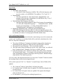
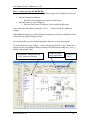
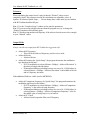
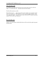
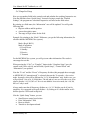
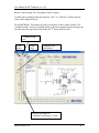
MICRF405/
MICRF505/MICRF506/
MICRF6x0
User Manual for RF TestBench
sw v.8.5
Micrel Norway AS
Strandveien 13 * 1366 LYSAKER * Norway
Tel: +47 67 83 08 00 * Fax: +47 67 83 08 10
User Manual for RF TestBench, sw v.8.5
Table of contents:
1.
2.
3.
Introduction................................................................................................................. 2
Install RF TestBench................................................................................................... 6
Main window .............................................................................................................. 8
3.1.
Select................................................................................................................... 8
3.2.
Information ....................................................................................................... 10
3.3.
Quick Setup....................................................................................................... 11
3.4.
Complete Setup................................................................................................. 17
3.5.
Control Word .................................................................................................... 20
3.6.
Schematics ........................................................................................................ 22
4.
Tools ..................................................................................................................... 22
4.1.
Tools Commands to Dev Board ….......................................................... 23
4.2.
Tools Bit Error Rate …............................................................................. 26
4.3.
Tools Frequency Error Estimator …........................................................ 26
4.4.
Tools Dev Board Information… .............................................................. 27
4.5.
Tools Calculate A, N, M … ..................................................................... 27
4.6.
Tools Calculate A, N, M Find 1…n frequencies, using modulator… .. 28
4.7.
Tools Calculate A, N, M Find 1…n freq., using two sets of dividers…28
4.8.
Tools Loop Filter ..................................................................................... 29
4.9.
Tools Loop Filter Find 2nd Order ….................................................... 29
4.10.
Tools Loop Filter Find 3rd Order …................................................. 30
4.11.
Tools Deviation.................................................................................... 31
4.12.
Tools Deviation Deviation Select Help …........................................ 31
5.
Options .................................................................................................................. 32
5.1.
Options Advanced Quick Setup… ............................................................ 32
6. Changes in this sw version........................................................................................ 33
Micrel Norway AS
1
User Manual for RF TestBench, sw v.8.5
1. Introduction
This document, “MICRF405/MICRF505/MICRF506/MICRF6x0 User Manual for RF
TestBench” describes how to set up and use RF TestBench. For details on the MICRF405
transmitter, the MICRF505/MICRF506 transceiver or the MICRF405/MICRF505/
MICRF506/MICRF6x0 development system: Please refer to the appropriate data sheet.
For the latest updates, visit www.micrel.com.
RF TestBench v.8.5 can be used with the following development systems:
MICRF405
MICRF505
MICRF506
MICRF600
MICRF610
MICRF620
The RF TestBench should be self-explaining. Use this document as a reference; it is not
necessary to read it through before starting to use RF TestBench. Note, however, that
some features require a special FW version (firmware = micro controller program). You
can use the “Get FW version” command to get the present FW version of your board
(refer to the following chapters). If you do not have the latest (or wanted) version, please
go to www.micrel.com for a free download. The MICRF405 firmware is in a project of
its own, with its own firmware version. All other development systems are collected in
the same project, with a common firmware version.
Also note: Any calculated value in this program should be considered a suggestion. When
transferred to a specific application, always test the RF performance. From v.8.1, the
program also suggests component values (like loop filter and antenna matching
components). Note that these values are suggestions only; always test in your own
application.
Important: New features are continuously added to RF TestBench (“RFTB”). If a
feature requires a special FW version (micro controller program): That FW version
is explicit mentioned in this user guide. From v8.4 of RFTB: If a dev board is
connected to your PC when you select a “Dev Board Connection”, then you will get
the FW version as well as the features not supported by the FW version (printed in
the “Information” section). Make sure to select RF device first, then select “Dev
Board Connection”. Features not supported will be disabled in RFTB.
Outline of this document:
Following this introduction, an Installation chapter is given. Then the different menu
items and dialog boxes are described. Observe that “MICRF6x0” in this document is a
short-term for “MICRF600/MICRF610/MICRF620”. Finally, the updates in this sw
Micrel Norway AS
2
User Manual for RF TestBench, sw v.8.5
version are listed. Note: Screenshots of several, but not all, windows are included. Also
note: Windows for the MICRF405 development system are typically different from the
other development systems, but the structure is equal.
Purpose of the RF TestBench:
RF TestBench can be used with or without a “development board”.
Users of the MICRF405 transmitter or MICRF505/MICRF506 radio transceiver can use
the RF TestBench to calculate fields in the control word to enter into the RF chip.
Typical examples are:
Get the complete control word to enter into the RF chip
Get the “M”, “A”, “N” dividers for a specific frequency or a set of frequencies
Get the “Mod_A” “Mod_I” and “RefClk_K” values for a specific deviation
Get the resulting deviation, bit rate etc for a specific set of parameters
Get component values to use with the MICRF405/MICRF505/MICRF506 (note:
no components for the RF modules 600, 610, 620)
Get external component values for a specific loop filter
Main features:
The main window is split into several areas. There is a “Quick Setup” part (recommended
as a starting point!), a “Complete setup”, and a “Control Word” part. In addition, there is
a “Select” part and an “Information” part, as well as a schematics window.
And finally, there is a menu. The reader is encouraged to locate these parts in the picture
below (or refer to the other screen shots in this document).
Typically, when pressing any “Calc!” or “Transfer!” button, all the other fields in the
main window are updated. In addition, the “Information field” is updated.
Note that the first screen capture below is for the MICRF505 development system. A
similar window is used for the MICRF506/MICRF6x0 development system, while the
MICRF405 development system has a slightly different look; however, the main window
structure is the same. Refer to the 2nd screen shot below.
Micrel Norway AS
3
User Manual for RF TestBench, sw v.8.5
Micrel Norway AS
4
User Manual for RF TestBench, sw v.8.5
The main features include:
Quick Setup. Enter parameters like wanted bit rate and RF frequency. Then see what
the fields in the control word should be. Transfer control word to development board
(where it is stored in EEPROM). The user is encouraged to start here!
Complete Setup. Enter “fields” in the control word. Then see the resulting bit rate,
deviation etc. Transfer control word to development board (where it is stored in
EEPROM)
Control Word. Enter complete register values (which typically covers several
“fields” of the control word). Then see the resulting bit rate, deviation etc. Transfer
control word to development board (where it is stored in EEPROM)
Commands to development board. The set of commands to the board includes start
to transmit 1010…, get firmware version, restart micro controller, reset EEPROM and
read EEPROM. 2 sets of commands are included: One for the MICRF405, and one
for all other development systems.
Bit Error Rate (BER): (not for MICRF405) Apply a 1010… pattern from an
external source, and read out the number of bits read, the number of bits in error and
the resulting bit-error-rate (a 1010… bit pattern, not a random bit pattern is applied.
However, this test still gives an indication of the bit-error level). (This feature
requires FW v4 or later)
Frequency Error Estimator (FEE): (not for MICRF405) Read out the FEE for
different XCO-tune values, or find the best XCO tune value automatically (this
feature requires FW v2 or later)
Calculate the A, N, M frequency dividers. Find 1 or several frequencies or set of
frequencies
Loop filter. Find values of external components for the loop filter
Deviation help. Get suggestions for minimum deviation and filter settings, based on
RF frequency, xtal tolerance etc
Micrel Norway AS
5
User Manual for RF TestBench, sw v.8.5
2. Install RF TestBench
The installation of RF TestBench is straightforward:
Double-click “Setup.exe” and follow the on-screen instructions.
Note: This program requires “.NET Framework” (Microsoft) to be installed. If
this is not installed on your computer, you will get a message when you start the
installation: You will be asked if you want to download and install the program
“dotnetfx.exe ”. Please do (or visit Microsoft.com and search for “dotnetfx.exe”,
then download and run it.) Note, however, that this might send you to a newer
version of “dotnetfx.exe” (like 2.0). To make sure you get a compatible version,
follow this link (download version 1.1.):
o http://www.microsoft.com/downloads/details.aspx?FamilyId=262D25E3F589-4842-8157-034D1E7CF3A3&displaylang=en
To start RF TestBench:
Click the Start button on the Windows taskbar, click Programs, and then click RF
TestBench.
When the program starts, a welcome-message is displayed. Please read it, and
then press the OK button. Then the main window will be displayed.
First step:
As an initial step, make sure to select the correct RF device in the “Select” part of
the main window, refer to figure below. Observe the text in the “Information”
part, which is changed when a new part is selected (if you “select” the already
selected part, all parameters will be reset to default).
Then use the “Quick Setup” features as a starting point (observe the blue pushbuttons in this area)
Micrel Norway AS
6
User Manual for RF TestBench, sw v.8.5
Select
Micrel Norway AS
RF Device
Information
7
User Manual for RF TestBench, sw v.8.5
3. Main window
The “Main Window” is the window that pops up after you have read the welcome
message and pressed the OK button in the Welcome window.
Starting from v.8.1, the Main Window is completely re-organised. Here you will find:
“Select”
“Information”
“Quick Setup”
“Complete Setup”
“Control Word”
“Schematics”.
These items are described in detail below.
In addition to these features, the Main Window holds a menu. The menu items of RF
TestBench are described in the next section.
Again, windows for the MICRF405 development system are typically different from the
other development systems, but the structure is equal.
3.1.Select
In the “Select” area, you select
RF Device
Crystal Frequency
Dev Board Connection
Refer to the text below.
RF Device
This is where the MICRF405, MICRF505 or MICRF506 chip, or a MICRF6x0 RF
module, is selected. If you are using a development board (“dev board”): Always select
the part mounted on the dev board. You don’t have to use a dev board; you can use this
program as a stand-alone program, without connecting your computer to a development
board.
Note that the selected RF part determines the default settings. For example, if
“MICRF505” is selected, then the default bit rate is set to 38462bps. If “MICRF600” is
Micrel Norway AS
8
User Manual for RF TestBench, sw v.8.5
selected, then the default bit rate is 19231 bps. For a complete list of default settings,
simply select a RF part and look at the settings (in “Quick Setup” and “Complete Setup”).
All settings are reset to default if a new RF part is selected, or if the already selected part
is selected again. Example: You have selected “MICRF505” initially. Then, after you
have made several changes, you might want to reset the settings to their default state.
You can do this by selecting “MICRF505” again.
Whenever you select a RF device, the “Information” window is updated. The schematic
is updated as well – observe: If you select a MICRF6x0 RF module, then there are no
external components, and a simple application drawing is shown.
If you have selected “MICRF405”, “MICRF505” or “MICRF506”, then you can click in
the schematics to get suggested component values in the “Information” area.
The presently selected RF part is always shown in the “Select” area.
Firmware (fw) requirements (dev board micro controller program) (this is the fw version
you need for the different devices):
MICRF505: all fw version can be used
MICRF506: requires fw v2 or later
MICRF600: requires fw v3 or later
MICRF610: requires fw v4 or later
MICRF620: requires fw v4 or later
MICRF405: all fw versions (note that MICRF405 firmware is a separate project,
with another firmware version than for the other development systems)
Observe: Some features requires a minimum fw version. Example: If you want to use the
bit-error-rate feature for the MICRF505 development system, make sure that the fw
version is 4 or higher.
Crystal Frequency
This is where you select the xtal to use with the RF part (observe that the MICRF6x0 RF
modules have an on-board xtal).
In many applications, a micro controller (MCU) is used to control the RF part. The MCU
may have it’s own xtal. Note that the xtal you select in the RF TestBench program, is the
one connected to the RF part.
Micrel Norway AS
9
User Manual for RF TestBench, sw v.8.5
Dev Board Connection
This is where you select the connection to the dev board (and connects to the dev board).
If you are not using a dev board, then select “NO PORT”. Else, select COMi, where i = 1,
2, 3, or 4.
Note: By selecting “NO PORT”, you close the presently selected port, that is: The port
can be used by another program you want to run at the same time.
If the port can’t be opened, you will get a message.
Before connecting to a dev board, make sure all cables are in place, and that the correct
DIP settings are made on the dev board (set all DIPs ON to use the dev board with RF
TestBench - refer to Dev board user manual).
When selecting a dev-board connection: If a dev board (with all DIPs ON) is connected
to the PC, then you will get the FW version of the dev board, as well as RFTB features
that this FW version does not support (if any). This will be printed in the “Information”
field.
3.2.Information
In the “Information” area, the program prints information about:
The presently selected RF device (when a RF part is selected) and
The “fields” in the control word (when you point to the name of a “field” in
“Complete Setup”) and
All “fields” in a register (when you point to the register address in “Control
Word”) and
Suggested component values for MICRF405/MICRF505/MICRF506 (when you
click at the schematics) and
(Maybe most important!) Calculated frequencies, bitrates etc when a “Calc!” or
“Transfer!” button is pressed.
The user is encouraged to explore all these features, and to use them frequently!
Note that the “old information” is over-written when “new information” is shown.
You can print out the contents of the “Information” field whenever you want. From the
menu in the main window, select File Print Information …
Micrel Norway AS
10
User Manual for RF TestBench, sw v.8.5
3.3.Quick Setup
This is the suggested starting-point (after you have selected a RF part). Simply make your
inputs (“Wanted” input fields) and press the blue “Calc!” button.
Observe the 3 blue buttons (described in detail below):
“Calc!”
“Transfer!”
“More!” (not for the MICRF405)
Observe the 3 input-fields below “Wanted” (described in detail below):
RF centre frequency (= RX- frequency)
Bitrate
RF Single-Sided Frequency Deviation
Observe the 3 read-only fields below “Achieved”, which corresponds to the “Wanted”
fields. Below, the MICRF505 case is described. MICRF405 users will get another
window (the 2nd screen capture below), but the structure is the same for all systems.
Quick Setup area
Micrel Norway AS
”Wanted”
input fields
”Achieved”
output fields
3 blue push buttons
11
User Manual for RF TestBench, sw v.8.5
”Wanted”
input fields
Quick Setup area
FSK/ASK/OOK
Micrel Norway AS
”Achieved”
output fields
2 blue push buttons
12
User Manual for RF TestBench, sw v.8.5
Input fields:
Wanted RF centre frequency
o Enter the RF centre frequency (in MHz). This will be the frequency used
in receive mode, or, for MICRF405: The middle of “Tx 0” and “Tx 1”.
Wanted Bitrate
o Enter the wanted bit rate. Note: Based on the “Wanted Bitrate”, the
program will set the type of modulation. (for MICRF6x0, only “2 set of
A,N,M modulation will be used)
Wanted Single-Sided Frequency Deviation
o Enter the single-sided deviation (in kHz). The frequency for transmitting a
“0” will be the “Wanted RF Frequency” – “Wanted Deviation”, and the
frequency for transmitting a “1” will be “Wanted RF Frequency” +
“Wanted Deviation” (this applies to FSK modulation).
Modulation (MICRF405 only): Select the wanted modulation type
(FSK/ASK/OOK/Spread Spectrum ASK). For other development systems, only
FSK is available. When a new modulation type is selected, then all fields are reset
to a default set of values. Use the program to find the default values.
Calc! and Transfer! Buttons:
When “Calc”! or “Transfer” is pressed, then the wanted settings are used to construct the
control word. In addition, several other fields will be used in the calculations (for a firsttime use, keep these unchanged):
The selected “RF Device” determines the default settings and the formulas for
constructing the RF frequencies. Make sure the correct RF part is selected.
The selected “Crystal Frequency”. This is used in the formulas
The fields in the control word that are not calc’ed in “Quick Setup”, are collected
from “Complete Setup”. Examples: PA, Sync_en, Mode, Load_en.
From the main menu, some “advanced” settings can be made. Select Options
Advanced Quick Setup … For example, you can change the tolerances used
when calculating the frequencies (the target will always be the “Wanted Settings”
when the blue Calc! button is pressed.)
If you are using a development board, then you can use the “Transfer!” button to transfer
the resulting control word to the development board.
After you have pressed “Calc”! or “Transfer!” in “Quick Setup”, then all fields will be
updated:
The “Achieved” fields in “Quick Setup” will show the results
In “Complete Setup” all field values are updated. The fields that changed value
are shown in red.
In “Control Word” all register values are updated. The registers that changed
value are shown in red.
In “Information”, you will get the resulting frequencies etc.
Micrel Norway AS
13
User Manual for RF TestBench, sw v.8.5
More… button: (not for the MICRF405)
If you press the “More…” button, then 2 additional settings will be displayed. These are:
Wanted Comparison frequency
o Enter the wanted comparison frequency (in kHz) here
Wanted Switch-cap cut off frequency
o Enter the wanted cut-off frequency for the switch-cap filter here
At the same time, the button is changed to “Less… ”. Press it to hide the additional
settings.
If the additional settings are visible, then these settings are used in the calculations. If not
visible, then the default settings are used.
It is recommended to use the default settings the first-time you use this program.
To get the figure below, the “More…” button was pressed, then the “Calc!” button was
pressed. Observe the additional fields, the name of the blue button (changed to “Less…”)
and the “Information” field.
”Information” changed after the
“Calc!” button was pressed
Micrel Norway AS
Additional Quick
Setup Input fields
Changed to
”Less...”
14
User Manual for RF TestBench, sw v.8.5
Tolerance:
When calculating the control word, it may be that the “Wanted” values are not
completely found. The tolerances used in the calculations are adjustable, select
Options Advanced Quick Setup … . Do not change these values until you are familiar
with RF TestBench and the RF part.
Hint 1: Use the “Complete Setup” window to fine-tune the parameters.
Hint 2: If you can accept a higher tolerance than the program uses, try to change the
“Wanted” parameters and calculate again.
Hint 3: Consider using another xtal frequency if the achieved results are not close enough
to your “Wanted” values.
Output Fields:
Always consider any output from RF TestBench a suggestion only!
Achieved RF Frequency
o This will be the achieved frequency used in receive mode
Achieved Bit rate
o Achieved bit rate
Achieved Deviation (In “Quick Setup”, the program determines the modulation
type based on the bit rate):
o If VCO modulation is selected (bitrate >20kbps): “Achieved Deviation” is
the achieved single-sided deviation
o If Internal modulation (switching between two sets of A, N, M dividers) is
selected (bitrate <=20kbps): “Achieved Deviation” is the middle of the tx0
and tx1 frequency deviation
If the additional fields are visible (not for MICRF405):
Achieved Comparison Frequency (In “Quick Setup”, the program determines the
modulation type based on the bitrate):
o If VCO modulation is selected (bitrate >20kbps): “Achieved Comparison
Frequency” is the achieved comp frequency
o If Internal modulation (switching between two sets of A, N, M dividers) is
selected (bitrate <=20kbps): “Achieved Comparison Frequency” is the inthe-middle value of comp freq for rx, tx0 and tx1
Achieved SC Cutoff
o Achieved switch capacitor filter cut off frequency
Micrel Norway AS
15
User Manual for RF TestBench, sw v.8.5
Store and restore values
It is possible to store and restore the present value of the control word. Use
Open… or
File Save As… from the menu in the main window.
File
The file will be stored as a .txt file.
Hint: Storing (Save As … ) the present control word is a handy way to export the control
word to e.g. another user of RF TestBench, or when requesting support. Then the “other
User” can restore (Open … ) the file to get the same values into RF TestBench (assuming
equal RF Device and Crystal Frequency).
Reset to Default values
Simply re-select the RF part, and the default values will be used (values equal to program
start-up values).
Micrel Norway AS
16
User Manual for RF TestBench, sw v.8.5
3.4.Complete Setup
Here you can update fields in the control word and calculate the resulting frequencies etc.
Note the difference from “Quick Setup”. Instead of trying to match the “Wanted
Settings”, the program now calculates frequencies etc based on the field values.
By pointing to a field name, the “Information” area will be updated. You will get the
following info:
Register address and bit-position
A more descriptive name
The range of legal values for the field.
Example: By pointing to the “Mode” field name, you get the following information (for
all other than the MICRF405 dev system):
Mode: (Reg0, Bit2-1)
Mode of operation:
0: Power Down
1: Standby
2: Receive
3: Transmit
For the MICRF405 dev system, you will get some other information. The reader is
encouraged to test this.
When pressing the “Calc!” or “Transfer!” button in the “Complete Setup” area, the
control word will be calc’ed, and all fields (“Quick Setup”, “Control Word” and
“Information”) are updated.
Note the “Tx-set” and the “Rx-set” of frequency dividers (this paragraph does not apply
to MICRF405): If “transmit mode” is selected, then use the Tx-set and v.v for receivemode. In practice, this will be different for “A, N, M modulation” only. In this case, you
will get/set all 3 sets of A, N, M dividers: The tx0 and tx1 sets as well as the rx set. Also
observe that the “A1, N1, M1 set” for rx is not editable. In receive-mode, the “A0, N0,
M0 -set” only is used.
Always make sure that all frequency dividers are > 0 (“A”-dividers can be 0, but for
simplicity: It is suggested to keep all dividers > 0). Setting an N –divider and/or an M divider equal to 0 will result in chip lock.
Like the “Quick Setup” feature, you can
Store/Restore control word values
Print “Information” field
Reset to default
Transfer to development board
Micrel Norway AS
17
User Manual for RF TestBench, sw v.8.5
Refer to “Quick Setup” for a description of these features.
If a field value is changed (after pressing any “Calc!” or “Transfer!” button), then the
value will be displayed in red.
For the MICRF405: The number of fields is too high to fit into a single window. The
“Complete Setup” section is scrollable. Refer to the screen captures on the next page; the
first one shows the upper half of the fields, the 2nd shows the lower half.
”Complete Setup”
area
”Field”
names
”Field”
values
2 standard color
push buttons
Frequency dividers for
“Transmit” and “Receive” mode
Micrel Norway AS
18
User Manual for RF TestBench, sw v.8.5
Micrel Norway AS
19
User Manual for RF TestBench, sw v.8.5
3.5.Control Word
Here you can update complete registers in the control word and calculate the resulting
frequencies etc. Note the difference from “Complete Setup”: In “Control Word” you
typically change several fields in one operation.
It is possible to change all bits, including “fixed” bits, by entering the address and value
directly. However, unused bits are not editable. Example: To set the value in register
0x0A equal to 0x1F: Enter “0A” in the address field; enter “1F” in the value-field. Then
press the “Calc!” button (the one in the “Control Word” area of the main window).
By pointing to a register address (“Reg #”), the “Information” area will be updated. You
will get the following info:
General info about “fixed” fields (this information is common for all registers,
even if the selected register does not have any fixed bits)
Bit-by-bit info for the selected register.
Example: By pointing to register address “00”, you get the following information (for all
other than the MICRF405 dev system):
Note: "Fixed" fields are also included. The "fixed" fields are not described in the
data sheet or in this program. Always maintain these bits to their "fixed" value.
Reg0:
Bit7: By_LNA
Bit6: PA2
Bit5: PA1
Bit4: PA0
Bit3: Sync_en
Bit2: Mode1
Bit1: Mode0
Bit0: Load_en
For the MICRF405 dev system, you will get some other information. The reader is
encouraged to test this.
When pressing the “Calc!” or “Transfer!” button in the “Control Word” area, the control
word will be calc’ed, and all fields (“Quick Setup”, “Complete Setup” and
“Information”) are updated.
Always make sure that all frequency dividers are > 0 (“A”-dividers can be 0, but for
simplicity: It is suggested to keep all dividers > 0). Setting an N –divider and/or an M divider equal to 0 will result in chip lock.
Like the “Quick Setup” and “Complete Setup” features, you can
Micrel Norway AS
20
User Manual for RF TestBench, sw v.8.5
Store/Restore control word values
Print “Information” field
Reset to default
Transfer to development board
Refer to “Quick Setup” for a description of these features.
If a register value is changed (after pressing any “Calc!” or “Transfer!” button), then the
value will be displayed in red.
Note that the register value must be entered as a hexadecimal number.
2 standard color
push buttons
Registervalue for Reg #0 (in hex format)
”Control Word” area
Micrel Norway AS
21
User Manual for RF TestBench, sw v.8.5
3.6.Schematics
In the “Schematics” area, you will get a typical application circuit.
If you have selected MICRF405/MICRF505/MICRF506:
By pressing the “+” push button, you will maximize the schematics. This is
achieved by double-clicking in the schematics area as well.
From the maximized schematics, you can select to print the drawing. Observe the
paper orientation (use “Landscape”).
In the main window, by clicking in the schematics area, you will get a list of
suggested component values in the “Information” area.
If you have selected MICRF6x0:
The schematics will show a simple application drawing, without any component
suggestions
(All components are on-board)
4.
Tools
In the following, the menu items and dialog boxes for the “Tools” will be described. A
menu item is always preceded with “ ” in the text below.
Note: The set of available commands is different for the MICRF405.
This is where you can give commands to the development board, or use some of the
special features like bit-error rate calculator.
Micrel Norway AS
22
User Manual for RF TestBench, sw v.8.5
The menu items in “RF TestBench” are described below.
4.1.
Tools
Commands to Dev Board …
The “Commands to Development Board” window pops up.
Micrel Norway AS
23
User Manual for RF TestBench, sw v.8.5
Push Buttons:
TX1010
o Start to transmit a 1010… pattern. Transmit-mode will be entered, overruling the entered control word. Modulation will stop if another command
is given.
TX Random (this feature requires FW v3 or later) (MICRF405: All fw versions)
o Start to transmit a random, Manchester-coded pattern. Transmit-mode will
be entered, over-ruling the entered control word. Modulation will stop if
another command is given.
Micrel Norway AS
24
User Manual for RF TestBench, sw v.8.5
Get FW v.
o Get the firmware version of the program presently in the micro controller.
New features may be added to new versions of the firmware. Make sure
your firmware version supports the features you want to use in RF
TestBench (if a feature requires a special FW version: It is described with
the feature in this manual).
Reset uC
o Restart micro controller
Reset EEP
o Fill EEPROM with default settings of the control word
Read EEP
o Read the presently stored EEPROM control word.
Use FLASH
o Instruct the development board to use the control word stored in FLASH
program memory of the micro controller. This is identical to the “Default”
settings.
Use EEP.
o Instruct the development board to use the control word stored in EEPROM
of the micro controller. The user-entered control word stored in EEPROM
is used in RF test modes, 2-way link test mode and simple byte transfer
mode.
Get Source
o Find out if the board will use the FLASH or the EEPROM memory (i.e.
the “default” and the “user-entered” control words, respectively)
Output fields:
FW version
o Present firmware version (micro controller program). FW version 99 is
used for test-programs.
Control word read from EEPROM
o Presently EEPROM-stored control word
Source is
o FLASH or EEPROM will be displayed
Transfer Status
o Messages related to the transfer of commands are displayed here. After
pressing Transfer, “Waiting…” will be displayed. If no response from
board, “Waiting…” will continue to be displayed. If response from board
is received, “Success” or “Error” will be displayed. If Error: Please test
communication cable, power, DIP switch setting and jumpers.
Micrel Norway AS
25
User Manual for RF TestBench, sw v.8.5
4.2.
Tools
Bit Error Rate …
(This feature requires FW v.4 or later) (This feature is not available for the
MICRF405)
The “Bit Error Rate (1010… test)” window pops up.
This feature requires the use of a development board. NOTE: Not all development
board firmware versions will support this feature.
Before starting, please make sure:
Make sure the dev. Board is in receive mode. This can be done via the
“Complete Setup … “ feature from the main window
Make sure a transmitter is present, and transmitting 1010… at the correct
frequency, with the correct deviation and so on. As a starting point, use
another development board to transmit 1010…
Start:
Press the “Start” button and observe the results. Note the time delay between
pressing the “Start” button and the update of the fields.
Note:
In the micro controller, the BER procedure will read bytes of the received RF
input. If the byte is equal to 10101010 or 01010101, then it is OK, and 0
errors are detected. If any other byte-value is read, it will be counted as 1
error.
Stop:
The BER procedure in the micro will stop if the “Stop” button is pressed, or if
any other command is given to the development board.
4.3.
Tools
Frequency Error Estimator …
(This feature requires FW v2 or later) (This feature is not available for the
MICRF405)
The “Frequency Error Estimator” window pops up. Please read all the text in this
window.
This feature requires the use of a development board. NOTE: Not all development
board firmware versions will support this feature.
Read the FEE value by pressing the “Read!” button, or by stepping XCO-tune value
up/down.
Micrel Norway AS
26
User Manual for RF TestBench, sw v.8.5
Pressing the “Tune” button will start a process to get the best XCO tune value.
Press the “Keep” button to use the XCO tune value from this dialog in the “Quick”
and “Complete” dialogs.
Please refer to the MICRF505/MICRF506 manual for details on the FEE.
Before using this feature:
Please read the MICRF505/MICRF506 user manual
Set the development board in rx, on the wanted frequency and bit rate (Use
“Quick Setup” or “Complete Setup”, press “Transfer”)
Apply a tx-signal (use another development board or a signal generator)
4.4.
Tools
Dev Board Information…
Here you get a picture of the development board.
Click in the picture to view help-button (and to hide them).
Click a help-button and read the information. In particular, the DIP-switch settings can be
useful to have available.
4.5.
Tools
Calculate A, N, M …
This is an aid for determining frequency dividers. You can use the “Quick Setup” as well
(to find 1 frequency / frequency set). Note that the tolerances in the Quick Setup dialog
are fixed, while they are adjustable here. This may give slightly different results.
Experiment with tolerances etc to get the frequency set you want!
Frequencies are calculated based on the following priorities:
1. As close to the RF frequency as possible
2. As close to the comparison frequency as possible
3. If a RF frequency is not a 100% hit, it must improve the best RF frequency found
with > 1kHz, or else the one with the “best”comparison frequency is used.
Please make sure that the correct RF device and crystal frequency are selected in the
main window before using these calculators.
Micrel Norway AS
27
User Manual for RF TestBench, sw v.8.5
4.6.
Tools Calculate A, N, M Find 1…n frequencies, using
modulator…
The “Calculate frequency dividers (A, N, M): Use modulator” window pops up.
1 or a number of frequencies can be calculated.
Fill in wanted frequencies etc and press the “Calc!” menu item. Then see the results.
It’s possible to store the results in a .txt file: Use the File Save As … menu item
from the menu in the calculator window (not the main window).
Note that new results over-write the old ones in the window.
4.7.
Tools Calculate A, N, M Find 1…n freq., using two sets of
dividers…
The “Calculate frequency dividers (A, N, M): Use two sets of dividers” window pops up.
1 or a number of frequency sets can be calculated.
Fill in wanted frequencies etc and press the “Calc!” menu item. See the results.
It’s possible to store the results in a .txt file: Use the File Save As … menu item
from the menu in the calculator window (not the main window).
Note that new results over-write the old ones in the window.
Micrel Norway AS
28
User Manual for RF TestBench, sw v.8.5
4.8.
Tools
Loop Filter
This can be used as an aid when determining component values of the external loop filter.
Note that the schematics are different for the MICRF405 and the MICRF505/506.
Always consider any output from RF TestBench a suggestion only!
4.9.
Tools
Loop Filter Find 2nd Order …
Enter parameters and calculate components, or
Enter component values and determine bandwidth and phase margin.
The standard E24 series is included to show available component values.
In addition, a drawing of the loop filter is shown.
Micrel Norway AS
29
User Manual for RF TestBench, sw v.8.5
4.10.
Tools
Loop Filter Find 3rd Order …
Enter parameters and calculate components, or
Enter component values and determine bandwidth and phase margin
The standard E24 series is included to show available component values.
In addition, a drawing of the loop filter is shown.
Note the achieved results with the given components.
The “T31” parameter: This is used to adjust the 3rd pole compared to the 1st pole.
The “Gamma” parameter: This is used to adjust the bandwidth versus the phase top.
In the figure below, loop filter components are entered, and then the “Determine
Bandwidth/Phase Margin!” button is pressed.
Micrel Norway AS
30
User Manual for RF TestBench, sw v.8.5
4.11.
Tools
Deviation
This is an aid for getting an idea of what the deviation and filter settings should be
4.12.
Tools
Deviation Deviation Select Help …
Enter values and calculate.
The formulas used are shown in the window. For the MICRF405, the “Filter” settings are
not available.
Note that the resulting “beta” will be higher than the input. The entered beta is considers
a “minimum beta”.
Micrel Norway AS
31
User Manual for RF TestBench, sw v.8.5
5.
Options
5.1.
Options
Advanced Quick Setup…
Here you can change the tolerances and several default values. Please read the text in the
window. Note: The “Advanced Options” window may look different from the picture
below.
Micrel Norway AS
32
User Manual for RF TestBench, sw v.8.5
6. Changes in this sw version
NOTE: The list below is simply a randomly ordered list of changes/updates from version
8.1.
2006 07 05 PKB v.8.5
MICRF505/506/6x0: New frequency sets (using Prescal_s = 0)
“Minimum spacing” calc’s included
MICRF405 868MHz: C6 changed to 5.6pF
MICRF610: Default comp. frequency set to 900kHz
Latest fw (micro controller program): MICRF505/506/6x0: v6. MICRF405: v2
2006 05 11 PKB v.8.4
Connecting to dev board:
o If you have connected a dev board (with all DIPs on) to the PC before a
“Dev Board Connection” is selected: In the “Information” field, you get
the dev-board FW (firmware) version as well as RFTB features not
supported by this FW version. Un-supported RFTB features are disabled
(“grayed out”).
MICRF405:
o When changing type of modulation from Quick Setup section: All control
word fields are reset to a default set of values.
o When changing type of modulation from Complete Setup or Control Word
sections: The change in modulation type is reflected in the radio buttons in
the Quick Setup section, but no reset to default values occur. In addition,
the “Deviation” field may change from “visible” to “invisible” or v.v.
o In ASK/OOK: The “Deviation” field in the Quick Setup section is not
visible.
o Different set of default values are used for FSK, ASK, OOK and SSASK
for the different frequency bands.
o In SSASK: The “spreading rate” is not changed when pressing the “Calc!”
button in the Quick Setup section. Previously, it was calculated to be 20
times the bit rate. Now it is the default value, unless changed by the user
in the Complete Section or the Control Word Section.
o In SSASK: When pressing the “Calc!” button in the Quick Setup section,
the comparison frequency and loop filter settings are not a function of the
bit rate. They will be set to the “default” values (get the “defaults” by
running the program). The ASKshape value is changed as a function of bit
rate.
o When printing the “Spread Rate” in the Information Section, then the
result is given in kHz, not Hz (Previously: Result in Hz, but the printed
unit was “kHz”).
When importing a file (any RF device), the “Crystal Frequency” is updated, based
on info in the imported file.
In the “Help” menu item: Added Internet Links
Micrel Norway AS
33
User Manual for RF TestBench, sw v.8.5
2006 02 13 PKB v.8.3
Included MICRF405
Changed 3rd order loop filter calculator
Included “A>N” test when calc’ing A,N and M
Included Picture of dev board with help-buttons
Included link to user guide in Help menu
Reorganised menu items into “Tools” and “Options”
2006 02 13 PKB v.8.2
For the MICRF6x0 modules, “Quick Setup” uses “A,N,M Modulation” only
Minor text/layout changes
2005 12 19 PKB v.8.1
New Installation procedure (double-click “setup.exe”)
Completely re-organised main window
Schematics and component suggestions
In Loop filter calculator: Possible to input component values and calculate the
resulting bandwidth and phase margin.
Micrel Norway AS
34