1
User’s
Manual
Model DY
Vortex Flowmeter
Model DYA
Vortex Flow Converter
FOUNDATION Fieldbus Communication Type
IM 01F06F00-01EN
IM 01F06F00-01EN
7th Edition
i
Model DY Vortex Flowmeter
Model DYA Vortex Flow Converter
FOUNDATION Fieldbus Communication Type
IM 01F06F00-01EN 7th Edition
Contents
1.
INTRODUCTION........................................................................................ 1-1
1.1
Using This Instrument Safety .......................................................................... 1-2
1.2
Warranty ............................................................................................................. 1-3
1.3
ATEX Documentation ....................................................................................... 1-4
2.
AMPLIFIER FOR FIELDBUS COMMUNICATION ................................... 2-1
3.
ABOUT FIELDBUS ................................................................................... 3-1
4.
5.
3.1
Outline ................................................................................................................ 3-1
3.2
Internal Structure of digitalYEWFLO .............................................................. 3-1
3.2.1
System/Network Management VFD .................................................. 3-1
3.2.2
Function Block VFD ........................................................................... 3-1
3.3
Logical Structure of Each Block ..................................................................... 3-2
3.4
Wiring System Configuration .......................................................................... 3-2
GETTING STARTED ................................................................................. 4-1
4.1
Connection of Devices ..................................................................................... 4-1
4.2
Host Setting ....................................................................................................... 4-2
4.3
Power-on of digitalYEWFLO and Bus............................................................. 4-2
4.4
Integration of DD ............................................................................................... 4-3
4.5
Reading the Parameters................................................................................... 4-3
4.6
Continuous Record of Values.......................................................................... 4-3
4.7
Generation of Alarm.......................................................................................... 4-4
CONFIGURATION ..................................................................................... 5-1
5.1
Network Design ................................................................................................. 5-1
5.2
Network Definition ............................................................................................ 5-1
5.3
Function Block Link Definitions ...................................................................... 5-2
5.4
Setting of Tags and Addresses .............................................................................. 5-3
5.5
Communication Setting ................................................................................... 5-4
5.6
5.5.1
VCR Setting ....................................................................................... 5-4
5.5.2
Function Block Execution Control...................................................... 5-5
Block Setting ..................................................................................................... 5-6
5.6.1
Link Objects ....................................................................................... 5-6
5.6.2
Trend Objects..................................................................................... 5-6
5.6.3
View Objects ...................................................................................... 5-7
5.6.4
Function Block Parameters................................................................ 5-7
7th Edition: Oct. 2013 (KP)
All Rights Reserved, Copyright © 2003, Yokogawa Electric Corporation
IM 01F06F00-01EN
ii
6.
7.
EXPLANATION OF BASIC ITEMS ........................................................... 6-1
6.1
Setting and Changing Parameters for the Whole Process .......................... 6-1
6.2
Transducer Block Parameters ......................................................................... 6-2
6.3
AI Function Block Parameters......................................................................... 6-4
6.4
Parameters of DI Function Block .................................................................... 6-6
6.5
Integral LCD Indicator ...................................................................................... 6-6
IN-PROCESS OPERATION ...................................................................... 7-1
7.1
Mode Transition ................................................................................................ 7-1
7.2
Generation of Alarm.......................................................................................... 7-1
7.3
7.2.1
Indication of Alarm.............................................................................. 7-1
7.2.2
Alarms and Events ............................................................................. 7-3
Simulation Function ......................................................................................... 7-3
8.
DEVICE STATUS ....................................................................................... 8-1
9.
GENERAL SPECIFICATIONS .................................................................. 9-1
10.
9.1
Standard Specifications ................................................................................... 9-1
9.2
Model and Suffix Codes ................................................................................... 9-3
9.3
Optional Specifications .................................................................................... 9-3
EXPLOSION PROTECTED TYPE INSTRUMENT ................................. 10-1
10.1
ATEX ................................................................................................................. 10-1
10.2
FM ..................................................................................................................... 10-5
10.3
IECEx .............................................................................................................. 10-11
10.4
CSA .................................................................................................................10-13
10.5
TIIS ..................................................................................................................10-14
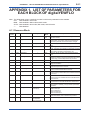
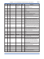
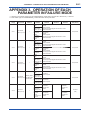
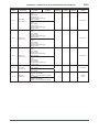
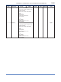
APPENDIX 1. LIST OF PARAMETERS
FOR EACH BLOCK OF digitalYEWFLO ...............................................A1-1
A1.1 Resource Block .................................................................................................... A1-1
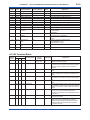
A1.2 Al Function Block ................................................................................................. A1-3
A1.3 Transducer Block ................................................................................................. A1-6
A1.4 DI Function Block ................................................................................................A1-11
APPENDIX 2. APPLICATION, SETTING AND CHANGE OF BASIC
PARAMETERS ........................................................................................A2-1
A2.1 Applications and Selection of Basic Parameters ............................................. A2-1
A2.2 Setting and Change of
Basic Parameters ........................................................................................... A2-2
A2.3 Setting the AI Function Blocks ........................................................................... A2-2
A2.4 Setting the Transducer Block ............................................................................. A2-4
A2.5 Setting the DI Function Blocks ........................................................................... A2-6
APPENDIX 3. OPERATION OF EACH PARAMETER IN FAILURE MODE ...A3-1
APPENDIX 4. FUNCTION DIAGRAMS OF FUNCTION BLOCKS .................A4-1
A4.1
AI Function Block........................................................................................... A4-1
A4.2
DI Function Block........................................................................................... A4-1
IM 01F06F00-01EN
iii
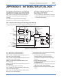
APPENDIX 5. INTEGRATOR (IT) BLOCK .......................................................A5-1
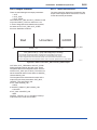
A5.1
Schematic Diagram of Integrator Block ..................................................... A5-1
A5.2
Input Process Section ................................................................................... A5-2
A5.3
A5.2.1
Determining Input Value Statuses ...................................................A5-2
A5.2.2
Converting the Rate .........................................................................A5-2
A5.2.3
Converting Accumulation .................................................................A5-3
A5.2.4
Determining the Input Flow Direction...............................................A5-3
Adder ............................................................................................................... A5-4
A5.3.1
Status of Value after Addition ...........................................................A5-4
A5.3.2
Addition ............................................................................................A5-4
A5.4
Integrator ........................................................................................................ A5-4
A5.5
Output Process .............................................................................................. A5-6
A5.6
A5.7
A5.5.1
Status Determination .......................................................................A5-6
A5.5.2
Determining the Output Value..........................................................A5-7
A5.5.3
Mode Handling ................................................................................A5-8
Reset................................................................................................................ A5-8
A5.6.1
Reset Trigger....................................................................................A5-8
A5.6.2
Reset Timing ....................................................................................A5-8
A5.6.3
Reset Process..................................................................................A5-9
List of Integrator Block Parameters ........................................................... A5-10
APPENDIX 6. Enhanced ARITHMETIC (AR) BLOCK ...................................A6-1
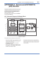
A6.1
Schematic Diagram of Arithmetic Block ................................................... A6-1
A6.2
Input Section .................................................................................................. A6-2
A6.3
A6.4
A6.2.1
Main Inputs ......................................................................................A6-2
A6.2.2
Auxiliary Inputs ................................................................................A6-2
A6.2.3
INPUT_OPTS .................................................................................A6-3
A6.2.4
Relationship between the Main Inputs and PV ...............................A6-3
Computation Section .................................................................................... A6-4
A6.3.1
Computing Equations .....................................................................A6-4
A6.3.2
Enhanced Computing Equations ....................................................A6-4
A6.3.3
Compensated Values ......................................................................A6-5
A6.3.4
Average Calculation ........................................................................A6-5
Output Section .............................................................................................. A6-5
A6.4.1
Mode Handling ................................................................................A6-6
A6.4.2
Status Handling ...............................................................................A6-6
A6.5
List of the Arithmetic Block Parameters ..................................................... A6-7
A6.6
Example of Connection ................................................................................. A6-9
A6.7
Setting Procedure of the Mass Flow Rate Calculation ............................ A6-10
IM 01F06F00-01EN
iv
APPENDIX 7. LINK MASTER FUNCTIONS ....................................................A7-1
A7.1
Link Active Scheduler.................................................................................... A7-1
A7.2
Link Master ..................................................................................................... A7-1
A7.3
Transfer of LAS .............................................................................................. A7-2
A7.4
LM Functions .................................................................................................. A7-3
A7.5
LM Parameters ............................................................................................... A7-4
A7.6
A7.5.1
LM Parameter List............................................................................A7-4
A7.5.2
Descriptions for LM Parameters ......................................................A7-6
Trouble Shooting ........................................................................................... A7-8
APPENDIX 8. PID BLOCK ................................................................................A8-1
A8.1
Function Diagram .......................................................................................... A8-1
A8.2
Functions of PID Block.................................................................................. A8-1
A8.3
Parameters of PID Block ............................................................................... A8-2
A8.4
PID Computation Details ............................................................................... A8-4
A8.5
Control Output................................................................................................ A8-4
A8.6
Direction of Control Action ........................................................................... A8-4
A8.7
Control Action Bypass .................................................................................. A8-5
A8.8
Feed-forward .................................................................................................. A8-5
A8.9
Block Modes ................................................................................................... A8-5
A8.10
Bumpless Transfer......................................................................................... A8-6
A8.11
Setpoint Limiters ............................................................................................ A8-6
A8.11.1
When PID Block is in AUTO Mode ..................................................A8-6
A8.11.2
When PID Block is in CAS or RCAS Mode......................................A8-6
A8.12
External-output Tracking .............................................................................. A8-7
A8.13
Measured-value Tracking.............................................................................. A8-7
A8.14
Initialization and Manual Fallback (IMAN) ................................................... A8-7
A8.15
Manual Fallback ............................................................................................. A8-8
A8.16
Auto Fallback.................................................................................................. A8-8
A8.17
Mode Shedding upon Computer Failure ..................................................... A8-8
A8.18
Alarms ............................................................................................................. A8-9
A8.19
A8.18.1
Block Alarm (BLOCK_ALM).............................................................A8-9
A8.18.2
Process Alarms ................................................................................A8-9
Example of Block Connections ............................................................................. A8-10
APPENDIX 9. DD MENU ...................................................................................A9-1
APPENDIX 10. METHOD ................................................................................A10-1
A10.1
Transducer Block ......................................................................................... A10-1
A10.2
Enhanced AR Block ..................................................................................... A10-5
IM 01F06F00-01EN
v
APPENDIX 11. SOFTWARE DOWNLOAD (Option /EE) ..............................A11-1
A11.1
Benefits of Software Download...................................................................A11-1
A11.2
Specifications................................................................................................A11-1
A11.3
Preparations for Software Downloading ....................................................A11-1
A11.4
Software Download Sequence ....................................................................A11-2
A11.5
Download Files ..............................................................................................A11-2
A11.6
Steps after Activating a Field Device ..........................................................A11-3
A11.7
Troubleshooting ............................................................................................A11-4
A11.8
Resource Block’s Parameters Relating to Software Download ..............A11-4
A11.9
System/Network Management VFD Parameters Relating to Software
Download .......................................................................................................A11-6
A11.9.1
Parameter List................................................................................A11-6
A11.9.2
Descriptions for Parameters ..........................................................A11-7
APPENDIX 12. DEVICEVIEWER WINDOW EXECUTED FROM PRM
(Plant Resource Manager) ...................................................................A12-1
Revision Information ...............................................................................................i
IM 01F06F00-01EN
1-1
<1. INTRODUCTION>
1.
INTRODUCTION
Thank you for purchasing FOUNDATION Fieldbus
communication type of digitalYEWFLO vortex
flowmeter.
To ensure correct use of the instrument, please
read this manual thoroughly and fully understand
how to operate the instrument before operating it.
This manual describes only those topics that are
required for operation of the FOUNDATION Fieldbus
communication type.
For other topics, please refer to User’s Manual for
vortex flowmeter (IM 01F06A00-01EN). Regarding
identical items, this manual has priority over IM
01F06A00-01EN.
Regarding This Manual
• This manual should be provided to the end
user.
• The contents of this manual may be changed
without prior notice.
• All rights are reserved. No part of this manual
may be reproduced in any form without
Yokogawa's written permission.
• Yokogawa makes no warranty of any kind with
regard to this material, including, but not limited
to, implied warranties of merchantability and
suitability for a particular purpose.
• All reasonable effort has been made to ensure
the accuracy of the contents of this manual.
However, if any errors or omissions are found,
please inform Yokogawa.
• The specifications covered by this manual are
limited to those for the standard type under the
specified model number break-down and do not
cover custom-made instruments.
• Please note that this manual may not be
revised for any specification changes,
construction changes or operating part changes
that are not considered to affect function or
performance.
• Yokogawa assumes no responsibilities for this
product except as stated in the warranty.
• If the customer or any third party is harmed by
the use of this product, Yokogawa assumes
no responsibility for any such harm owing to
any defects in the product which were not
predictable, or for any indirect damages.
Safety and Modification Precautions
• The following general safety precautions must
be observed during all phases of operation,
service, and repair of this instrument. Failure
to comply with these precautions or with
specific WARNINGS given elsewhere in
this manual violates safety standards of
design, manufacture, and intended use of the
instrument. Yokogawa assumes no liability
for the customer's failure to comply with these
requirements. If this instrument is used in
a manner not specified in this manual, the
protection provided by this instrument may be
impaired.
• Yokogawa will not be liable for malfunctions or
damage resulting from any modification made
to this instrument by the customer.
• The following safety symbol marks are used in
this manual and instrument.
WARNING
A WARNING sign denotes a hazard. It calls
attention to procedure, practice, condition or the
like, which, if not correctly performed or adhered
to, could result in injury or death of personnel.
CAUTION
A CAUTION sign denotes a hazard. It calls
attention to procedure, practice, condition or the
like, which, if not correctly performed or adhered
to, could result in damage to or destruction of the
product.
IMPORTANT
An IMPORTANT sign denotes that attention is
required to avoid damage to the instrument or
system failure.
NOTE
A NOTE sign denotes information necessary
for essential understanding of operation and
features.
IM 01F06F00-01EN
<1. INTRODUCTION>
1.1
Using This Instrument Safety
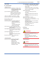
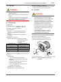
(1) Installation
WARNING
• Installation of the vortex flowmeter must
be performed by expert engineer or skilled
personnel. No operator shall be permitted to
perform procedures relating to installation.
• The vortex flowmeter must be installed within
the specification conditions.
• The vortex flowmeter is a heavy instrument.
Be careful that no damage is caused to
personnel through accidentally dropping
it, or by exerting excessive force on the
vortex flowmeter. When moving the vortex
flowmeter, always use a trolley and have at
least two people carry it.
• When the vortex flowmeter is processing
hot fluids, the instrument itself may become
extremely hot. Take sufficient care not to get
burnt.
• Where the fluid being processed is a toxic
substance, avoid contact with the fluid and
avoid inhaling any residual gas, even after
the instrument has been taken off the piping
line for maintenance and so forth.
• Do not open the cover in wet weather or
humid environment. When the cover is open,
stated enclosure protection is not applicable.
• Do not apply excessive weight, for example,
a person stepping on the vortex flowmeter.
• All procedures relating to installation must
comply with the electrical code of the country
where it is used.
(2) Wiring
WARNING
• The wiring of the vortex flowmeter must
be performed by expert engineer or skilled
personnel. No operator shall be permitted to
perform procedures relating to wiring.
• When connecting the wiring, check that the
supply voltage is within the range of the
voltage specified for this instrument before
connecting the power cable. In addition,
check that no voltage is applied to the power
cable before connecting the wiring.
1-2
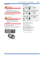
(3) Operation
WARNING
• Do not open the cover in wet weather or
humid environment. When the cover is open,
stated enclosure protection is not applicable.
• When opening the cover, wait for more than
3 minutes after turning off the power.
(4) Maintenance
WARNING
• Maintenance of the vortex flowmeter should
be performed by the trained personnel
having knowledge of safety standard. No
operator shall be permitted to perform any
operations relating to maintenance.
• Do not open the cover in wet weather or
humid environment. When the cover is open,
stated enclosure protection is not applicable.
• When opening the cover, wait for more than
3 minutes after turning off the power.
• Always conform to maintenance procedures
outlined in this manual. If necessary, contact
Yokogawa.
(5) Explosion Protected Type Instrument
WARNING
• The instruments are products which have
been certified as explosion proof type
instruments. Strict limitations are applied
to the structures, installation locations,
external wiring work, maintenance and
repairs, etc. of these instruments. Sufficient
care must be taken, as any violation of the
limitations may cause dangerous situations.
Be sure to read Chapter 10 “EXPLOSION
PROTECTED TYPE INSTRUMENT”
before handling the instruments. For TIIS
flameproof type instruments, be sure to
read “INSTALLATION AND OPERATING
PRECAUTIONS FOR TIIS FLAMEPROOF
EQUIPMENT” at the end of manual for the
vortex flowmeter (IM 01F06A00-01EN).
• Only trained persons use this instrument in
the industrial location.
• Take care not to generate mechanical
spark when access to the instrument and
peripheral devices in hazardous locations.
IM 01F06F00-01EN
<1. INTRODUCTION>
1.2
1-3
Warranty
• The terms of this instrument that are
guaranteed are described in the quotation.
We will make any repairs that may become
necessary during the guaranteed term free of
charge.
• Please contact our sales office if this instrument
requires repair.
• If the instrument is faulty, contact us with
concrete details about the problem and the
length of time it has been faulty, and state the
model and serial number. We would appreciate
the inclusion of drawings or additional
information.
• The results of our examination will determine
whether the meter will be repaired free of
charge or on an at-cost basis.
The guarantee will not apply in the
following cases:
• Damage due to negligence or insufficient
maintenance on the part of the customer.
• Problems or damage resulting from handling,
operation or storage that violates the intended
use and specifications.
• Problems that result from using or performing
maintenance on the instrument in a location
that does not comply with the installation
location specified by Yokogawa.
• Problems or damage resulting from repairs or
modifications not performed by Yokogawa or
someone authorized by Yokogawa.
• Problems or damage resulting from
inappropriate reinstallation after delivery.
• Problems or damage resulting from disasters
such as fires, earthquakes, storms, floods, or
lightning strikes and external causes.
Trademarks:
• ‘digitalYEWFLO’, ‘DY’, ‘DYA’, ‘DYC’ and
‘BRAIN TERMINAL’ are registered trademarks
of Yokogawa Electric Corporation. Company
names and product names used in this material
are registered trademarks or trademarks of their
respective owners.
• In this manual, trademarks or registered
trademarks are not marked with ™ or ®.
IM 01F06F00-01EN
<1. INTRODUCTION>
1.3
1-4
ATEX Documentation
This is only applicable to the countries in European Union.
GB
DK
SK
CZ
I
LT
E
LV
EST
NL
PL
SF
SLO
P
H
F
BG
D
RO
S
M
GR
IM 01F06F00-01EN
<2. AMPLIFIER FOR FIELDBUS COMMUNICATION>
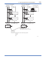
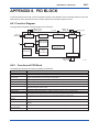
2.
2-1
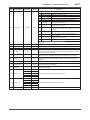
AMPLIFIER FOR FIELDBUS
COMMUNICATION
Refer to IM 01F06A00-01EN for the details of
the amplifier. This section encompasses topics
applicable to only the Fieldbus communication type.
(1) The Fieldbus communication type has no local
key access function.
(2) The Fieldbus communication type has no
BT200 (BRAIN TERMINAL) connection pin.
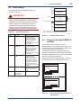
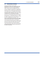
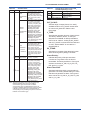
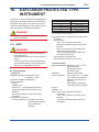
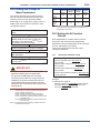
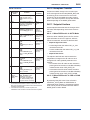
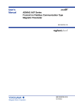
(3) The Fieldbus communication type has a
simulation function. The SIMULATE_ENABLE
switch is mounted on the amplifier. Refer to
Section 7.3 “Simulation Function” for details of
the simulation function.
Amplifier unit
SIMULATE_ENABLE switch
1
2
Figure 2.1
F0201.ai
Amplifier for Fieldbus Communication
IM 01F06F00-01EN
3-1
<3. ABOUT FIELDBUS>
3.
3.1
ABOUT FIELDBUS
Outline
Fieldbus is a bi-directional digital communication
protocol for field devices, which offers an
advancement in implementation technologies for
process control systems and is widely employed by
numerous field devices.
The Fieldbus communication type of the
digitalYEWFLO employs the specification
standardized by the Fieldbus FOUNDATION, and
provides interoperability between Yokogawa
devices and those produced by other
manufacturers. Featuring two AI and two DI function
blocks in each, the Fieldbus communication type’s
software enables a flexible instrumentation system
to be implemented.
For information on other features, engineering,
design, construction work, startup and maintenance
of Fieldbus, refer to “Fieldbus Technical Information”
(TI 38K03A01-01E).
3.2
Internal Structure of
digitalYEWFLO
Each digitalYEWFLO contains two Virtual Field
Devices (VFDs) that share the following functions.
3.2.1 System/Network Management VFD
• Sets node addresses and Physical Device tags
(PD Tag) necessary for communication.
• Controls the execution of function blocks.
• Manages operation parameters and
communication resources (Virtual
Communication Relationship: VCR).
3.2.2 Function Block VFD
(1) Resource (RS) block
• Manages the status of digitalYEWFLO
hardware.
• Automatically informs the host of any detected
faults or other problems.
(2) Transducer (TR) block
• Converts the flow sensor output to the
volumetric flow rate signal and transfers to an AI
function block (AI1).
• With the option /MV
- Converts temperature sensor output to the
process fluid temperature and calculates the
fluid density.
- Calculates the mass flow rate from the fluid
density thus obtained and the volumetric flow
rate obtained with the flow sensor.
- Transfers these calculation results to AI
function blocks.
• Transfers limit switch signals to DI function
blocks.
(3) AI function blocks (three)
• Output flowrate and temperature.
• Condition raw data from the TR block.
• Carry out scaling and damping (with a firstorder lag), and allow input simulation.
(4) DI function blocks (two)
• Limit switches for the flow rate and temperature
(option /MV).
(5) IT function block (one)
• Accumulate given values.
(6) AR function block (one)
• Calculate input values.
(7) PID function block (option /LC1)
• Performs the PID computation based on the
deviation of the measured value from the
setpoint.
IM 01F06F00-01EN
<3. ABOUT FIELDBUS>
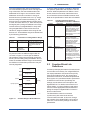
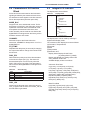
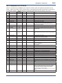
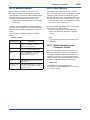
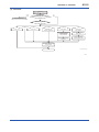
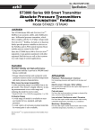
3.3
3-2
Logical Structure of Each
Block
digital
YEWFLO
System/network management VFD
PD tag
Communication parameters
Node address
VCR
Function block
execution schedule
Link master
Function block VFD
PID function block
(option /LC1)
IT function
block
OUT
AR function
block
Sensor
input
OUT
OUT
block
AI1 function
block
Flow
rate Block tag
Parameters signal
Output
Flow sensor
Block tag
AI3 function
AI2 function block
(outputting the
temperature for a
model with the option
/MV)
OUT
Transducer
block
Temp.
signal
(option
/MV)
OUT
Sensor
input
OUT
DI1 function
block
OUT
Temp. sensor
(option /MV)
DI2 function
block
Parameters
OUT
Resource block
Block tag
Parameters
F0301.ai
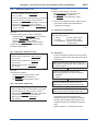
Figure 3.1
Logical Structure of Each Block
Various parameters, the node address, and the PD
tag shown in Figure 3.1 must be set before using
the device. Refer to Chapter 4 and onward for the
setting procedures.
3.4
Wiring System Configuration
The number of devices that can be connected to
a single bus and the cable length vary depending
on system design. When constructing systems,
both the basic and overall design must be carefully
considered to achieve optimal performance.
IM 01F06F00-01EN
4-1
<4. GETTING STARTED>
4.
GETTING STARTED
Fieldbus is fully dependent upon digital
communication protocol and differs in operation
from conventional 4 to 20 mA transmission
and the BRAIN communication protocol. It is
recommended that novice users use fieldbus
devices in accordance with the procedures
described in this section. The procedures assume
that fieldbus devices will be set up on a bench or in
an instrument shop.
4.1
Connection of Devices
The following instruments are required for use with
Fieldbus devices:
• Power supply:
Fieldbus requires a dedicated power supply. It
is recommended that current capacity be well
over the total value of the maximum current
consumed by all devices (including the host).
Conventional DC current cannot be used as is.
• Cable:
Used for connecting devices. Refer to “Fieldbus
Technical Information” (TI 38K03A01-01E) for
details of instrumentation cabling. For laboratory
or other experimental use, a twisted pair cable
two to three meters in length with a cross section
of 0.9 mm2 or more and a cycle period of within
5 cm (2 inches) may be used. Termination
processing depends on the type of device being
deployed. For the digitalYEWFLO, use terminal
lugs applicable to M4 screw terminals. Some
hosts require a connector.
Refer to Yokogawa when making arrangements to
purchase the recommended equipment.
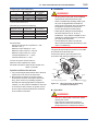
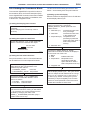
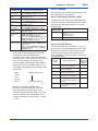
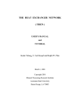
Connect the devices as shown in Figure 4.1.
Connect the terminators at both ends of the
trunk, with a minimum length of the spur laid for
connection.
The polarity of signal and power must be
maintained.
Fieldbus power
supply
• Terminator:
Fieldbus requires two terminators. Refer to
the supplier for details of terminators that are
attached to the host.
digitalYEWFLO
+
HOST
–
Terminator
• Field devices:
Connect your Fieldbus communication type
digitalYEWFLO to a fieldbus. Two or more
digitalYEWFLOs and other field devices can be
connected. For the terminal assignment on the
digitalYEWFLO, see Table 4.1.
Table 4.1
Terminal Connection for
digitalYEWFLO
Terminal Symbols
SUPPLY +
SUPPLY –
Description
Fieldbus Communication Signal
Terminals
Grounding Terminal
Terminator
F0401.ai
Figure 4.1
Device Connection
IMPORTANT
Connecting a Fieldbus configuration tool
to a loop with its existing host may cause
communication data scrambling resulting
in a functional disorder or a system failure.
Disconnect the relevant control loop from the bus
if necessary.
• Host:
Used for accessing field devices. A
dedicated host (such as DCS) is used for
an instrumentation line while dedicated
communication tools are used for experimental
purposes. For operation of the host, refer to the
instruction manual for each host. No other details
on the host are given in this manual.
IM 01F06F00-01EN
4-2
<4. GETTING STARTED>
4.2
Host Setting
0x00
Not used
To activate Fieldbus, the following settings are
required for the host.
0x0F
0x10
Bridge device
0x13
0x14
IMPORTANT
Do not turn off the power immediately after
setting. When the parameters are saved to the
EEPROM, the redundant processing is executed
for the improvement of reliability. If the power
is turned off within 60 seconds after setting is
made, the modified parameters are not saved
and the settings may return to the original values.
Table 4.2
Operation Parameters
LM device
V(FUN)
Unused
V(FUN)+V(NUN)
V(NUN)
BASIC device
0xF7
0xF8
Default address
0xFB
0xFC
Portable device address
0xFF
Note 1: LM device: with bus control function (Link Master function)
Note 2: BASIC device: without bus control function
F0402.ai
Symbol
V (ST)
V (MID)
V (MRD)
V (FUN)
V (NUN)
Parameter
Slot-Time
Description and Settings
Indicates the time necessary
for immediate reply of
the device. Unit of time
is in octets (256 μs). Set
maximum specification
for all devices. For
digitalYEWFLO, set a value
of 4 or greater.
Minimum-InterMinimum value of
PDU-Delay
communication data
intervals. Unit of time is in
octets (256 μs). Set the
maximum specification
for all devices. For
digitalYEWFLO, set a value
of 4 or greater.
Maximum-ReplyThe worst case time
Delay
elapsed until a reply is
recorded. The unit is
Slot-time; set the value so
that V (MRD) x V (ST) is
the maximum value of the
specification for all devices.
For digitalYEWFLO, the
setting must be a value of 12
or greater.
First-Unpolled-Node Indicate the address next
to the address range used
by the host. Set 0x15 or
greater.
Number-ofUnused address range.
consecutiveUnpolled-Node
Figure 4.2
4.3
Available Address Range
Power-on of digitalYEWFLO
and Bus
Turn on the power to the host, bus, and
digitalYEWFLO. If any segments do not light, or if
a current anomaly occurs, check the voltage of the
power supply for the digitalYEWFLO.
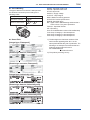
The device information, including PD tag, Node
address, and Device ID, is described on the sheet
attached to digitalYEWFLO. The device information
is given in duplicate on this sheet.
Using the host device display function, check that
the digitalYEWFLO is in operation on the bus.
DEVICE INFORMATION
Device ID:5945430009XXXXXXXX
PD Tag:XXXXXX
Device Revision:X
Node Address:0xXX
Serial No.:XXXXXXXXXXXXXXXXX
Physical Location:
Note:
Our Device Description Files and Capabilities Files available at
http://www.yokogawa.com/fld/ (English)
http://www.yokogawa.co.jp/fld/ (Japanese)
DEVICE INFORMATION
Device ID:5945430009XXXXXXXX
PD XXXXXX
Device Revision:X
Node Address:0xXX
Serial No.:XXXXXXXXXXXXXXXXX
Physical Location:
Note:
Our Device Description Files and Capabilities Files available at
http://www.yokogawa.com/fld/ (English)
http://www.yokogawa.co.jp/fld/ (Japanese)
F0403.ai
Figure 4.3
Device Information Sheet Attached to
digitalYEWFLO
IM 01F06F00-01EN
4-3
<4. GETTING STARTED>
Unless otherwise specified, the following settings
are in effect when shipped from the factory.
If no digitalYEWFLO is detected, check the
available address range. If the node address and
PD Tag are not specified when ordering, default
value is factory set. If two or more digitalYEWFLOs
are connected at a time with default value, only
one digitalYEWFLO will be detected from host as
digitalYEWFLOs have the same initial address.
Connect the digitalYEWFLOs one by one and set a
unique address for each.
4.4
Integration of DD
If the host supports DD (Device Description), the
DD of the digitalYEWFLO needs to be installed.
Check if host has the following directory under its
default DD directory.
594543
: the manufacturer number of
Yokogawa Electric Corporation
0009 : the device number of digitalYEWFLO
If this directory is not found, the DD for the
digitalYEWFLO has not yet been installed. Create
this directory and copy the DD files (0m0n.ffo and
0m0n.sym to be supplied separately where m and
n are numerals) to it. If you do not have the DD files
for the digitalYEWFLO, you can download them
from our web site.
Visit the following web site.
http://www.yokogawa.com/fld/
Once the DD is installed in the directory, the
name and attribute of all parameters of the
digitalYEWFLO are displayed.
Off-line configuration is possible using the
capabilities file.
NOTE
When using a capabilities file (CFF), make sure
you use the right file for the intended device. The
digitalYEWFLO is offered in two types in terms of
capabilities:
• General type:
AI function blocks (three), DI function blocks
(two), AR function block (one), and IT
function block (one).
• With the option /LC1: A PID function block
Using the wrong CFF file may result in an
error when downloading the configured data
to the device. Also, use the right DD files that
accommodate the revision of the intended
device.
4.5
Reading the Parameters
To read digitalYEWFLO parameters, select the AI
block of the digitalYEWFLO from the host screen
and read the OUT parameter. The current flow rate
is displayed. Check that MODE_BLK of the function
block and resource block is set to AUTO.
4.6
Continuous Record of
Values
If the host has a function of continuously records the
indications, use this function to list the indications
(values). Depending on the host being used, it may
be necessary to set the schedule of Publish (the
function that transmits the indication on a periodic
basis).
IM 01F06F00-01EN
<4. GETTING STARTED>
4.7
4-4
Generation of Alarm
If the host is allowed to receive alarms,
generation of an alarm can be attempted from the
digitalYEWFLO. In this case, set the reception of
alarms on the host side. The digitalYEWFLO’s
VCR-7 is factory-set for this purpose. For practical
purposes, all alarms are placed in a disabled status;
for this reason, it is recommended that you first use
one of these alarms on a trial basis. Set the value of
link object-3 (index 30002) as “0, 299, 0, 6, 0”. Refer
to Subsection 5.6.1 “Link Objects” for details.
Since the LO_PRI parameter (index 4029) of the AI
block is set to “0”, try setting this value to “3”. Select
the Write function from the host in operation, specify
an index or variable name, and write “3” to it.
The LO_LIM parameter (index 4030) of the AI block
determines the limit at which the lower bound alarm
for the process value is given. In usual cases, a
very small value is set to this limit. Set smaller value
than 100% value of XD_SCALE (same unit). Since
the flow rate is almost 0, a lower bound alarm is
raised. Check that the alarm can be received at the
host. When the alarm is confirmed, transmission of
the alarm is suspended.
IM 01F06F00-01EN
<5. CONFIGURATION>
5.
CONFIGURATION
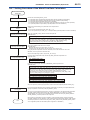
This chapter describes how to adapt the function
and performance of the digitalYEWFLO to suit
specific applications. Because multiple devices are
connected to Fieldbus, it is important to carefully
consider the device requirements and settings
when configuring the system. The following steps
must be taken.
(1) Network design
Determines the devices to be connected to
Fieldbus and checks the capacity of the power
supply.
(2) Network definition
Determines the PD tag and node addresses for
all devices.
(3) Definition of combining function blocks
Determines how function blocks are combined.
(4) Setting tags and addresses
Sets the PD Tag and node addresses for each
device.
(5) Communication setting
Sets the link between communication
parameters and function blocks.
(6) Block setting
Sets the parameters for function blocks.
The following section describes in sequence each
step of this procedure. The use of a dedicated
configuration tool significantly simplifies this
procedure. Refer to APPENDIX 7 “LINK MASTER
FUNCTIONS” when the digitalYEWFLO is used as
Link Master.
5.1
5-1
Network Design
Select the devices to be connected to the Fieldbus
network. The following are essential for the
operation of Fieldbus.
• Power supply
Fieldbus requires a dedicated power supply. It
is recommended that current capacity be well
over the total value of the maximum current
consumed by all devices (including the host).
Conventional DC current cannot be used as
power supply.
• Terminator
Fieldbus requires two terminators. Refer to
the supplier for details of terminators that are
attached to the host.
• Field devices
Connect the field devices necessary for
instrumentation. The digitalYEWFLO has passed
the interoperability test conducted by The
Fieldbus Foundation. In order to properly start
Fieldbus, it is recommended that the devices
used satisfy the requirements of the above test.
• Host
Used for accessing field devices. A minimum of
one device with bus control function is needed.
• Cable
Used for connecting devices. Refer to “Fieldbus
Technical Information” (TI 38K03A01-01E) for
details of instrumentation cabling. Provide a
cable sufficiently long to connect all devices. For
field branch cabling, use terminal boards or a
connection box as required.
First, check the capacity of the power supply.
The power supply capacity must be greater than
the sum of the maximum current consumed by
all devices to be connected to Fieldbus. For the
digitalYEWFLO, the maximum current (power
supply voltage: 9 to 32 VDC) is 15 mA. The cable
used for the spur must be of the minimum possible
length.
5.2
Network Definition
Before connection of devices with Fieldbus, define
the Fieldbus network. Allocate PD tags and node
addresses to all devices (excluding such passive
devices as terminators).
The PD tags are the same as conventional
tag numbers assigned to devices. Up to 32
alphanumeric characters may be used for definition
of the PD tag for each device. Use hyphens as
delimiters as required.
IM 01F06F00-01EN
<5. CONFIGURATION>
The node addresses are used to locate devices
for communication purposes. Since a PD tag is too
long a data value, the host substitutes the node
addressed for PD tags in communication. Node
addresses can be set to numbers in a range of
decimal 20 to 247 (hexadecimal 14 to F7). Assign
devices having link master functionality (i.e., LM
devices) from the smallest address number (0x14)
in order, and other devices (i.e., basic devices) from
the largest (0xF7). Assign an address in the range
for basic devices to a digitalYEWFLO. Only when
using a digitalYEWFLO with LM function as an
LM device, assign an address in the range for LM
devices to it. These address ranges are determined
by the following parameters.
Table 5.1
To ensure stable operation of Fieldbus, determine
the operation parameters and set them to the LM
devices. While the parameters in Table 5.2 are to
be set, the worst-case value of all the devices to
be connected to the same Fieldbus must be used.
Refer to the specification of each device for details.
Table 5.2
V (NUN)
Parameters
Description
First-Unpolled-Node Indicates the address next
to the address range used
for the host or other LM
device.
Number-ofUnused address range
consecutiveUnpolled-Node
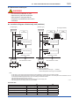
Any devices within an address range written as
“Unused” in Figure 5.1 cannot join the fieldbus.
Other address ranges are periodically scanned to
find any devices newly joining the fieldbus. Do not
widen the available address ranges unnecessarily;
the fieldbus communication performance may be
severely degraded.
0x00
Unused
0x0F
0x10
Bridge device
0x13
0x14
LM devices
V(FUN)
Unused
V(FUN)+V(NUN)
V(NUN)
Basic devices
0xF7
0xF8
Default addresses
0xFB
0xFC
Portable device addresses
0xFF
F0501.ai
Figure 5.1
Available Range of Node Addresses
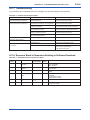
Operation Parameter Values of
digitalYEWFLO to be Set to LM Device
Symbol
V (ST)
Parameters
Slot-Time
V (MID)
Minimum-InterPDU-Delay
V (MRD)
MaximumResponse-Delay
Parameters for Setting Address Range
Symbol
V (FUN)
5-2
5.3
Description and Settings
Indicates the time
necessary for immediate
reply of the device. Unit of
time is in octets (256 μs).
Set maximum specification
for all devices. For a
digitalYEWFLO, set a value
of 4 or greater.
Minimum value of
communication data
intervals. Unit of time is in
octets (256 μs). Set the
maximum specification
for all devices. For a
digitalYEWFLO, set a value
of 4 or greater.
The worst case time
elapsed until a reply is
recorded. The unit is
Slot-time; set the value so
that V (MRD) x V (ST) is
the maximum value of the
specification for all devices.
For a digitalYEWFLO, value
of V(MRD) x V (ST) must be
12 or greater.
Function Block Link
Definitions
Link the input/output parameters of function blocks
to each other as necessary. For a digitalYEWFLO,
the output parameters of three AI blocks (OUTs),
those of two DI blocks (OUT_Ds), input/output
parameters of AR block, IT block and optional PID
block (option /LC1) should be linked to parameters
of different function blocks. Specifically, link
settings must be written to the link object in the
digitalYEWFLO. For details, refer to Section 5.6
“Block Setting.” It is also possible to read values
from the host at appropriate intervals instead of
linking the outputs of digitalYEWFLO’s function
blocks to other blocks.
The linked blocks need to be executed
synchronously with other blocks and the
communication schedule. In this case, change
the schedule of the digitalYEWFLO according to
Table 5.3, in which factory settings are shown in
parentheses.
IM 01F06F00-01EN
5-3
<5. CONFIGURATION>
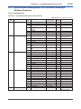
Table 5.3
Index
269 (SM)
276 (SM)
277 (SM)
278 (SM)
to
289 (SM)
Function Block Execution Schedule of
the digitalYEWFLO
Setting (Factory Setting
in Parentheses)
MACROCYCLE_
Repetition period of control
DURATION
or measurement, i.e.,
macrocycle; to be set as a
multiple of 1/32 ms (32000
= 1 second)
FB_START_ENTRY.1
Start time of the AI1
block represented as the
elapsed time from the start
of each macrocycle; to be
set as a multiple of 1/32 ms
(0 = 0 ms)
FB_START_ENTRY.2
Start time of the PID block
(optional) represented as
the elapsed time from the
start of each macrocycle;
to be set as a multiple of
1/32 ms (9600 = 300 ms)
FB_START_ENTRY.3 to Not set.
FB_START_ENTRY.14
FI103
FI100
OUT
Parameters
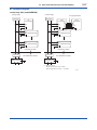
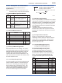
A maximum of 29 ms is taken for execution of each
AI block. Arrange the communication schedule
for an AI block’s data that is to be transferred to its
downstream block in such a way that it starts after a
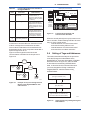
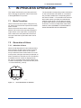
lapse of longer than 30 ms.
Figure 5.3 shows typical function block and
communication schedules for the loop shown in
Figure 5.2.
FIC100
digitalYEWFLO
#1
FIC200
FI100
digitalYEWFLO
#2
FI200
IN
CAS_IN
FIC100
FC100
BKCAL_IN
FC200
FI200
Function
Block
Schedule
FI200
BKCAL_OUT
FIC200
FC100
IN
BKCAL_IN BKCAL_OUT
OUT
Communication
Schedule
Unscheduled
Communication
Scheduled
Communication
F0503.ai
Figure 5.3
Function Block Schedule and
Communication Schedule
When the control period (macrocycle) is set to more
than 4 seconds, set the following interval to be more
than 1% of the control period.
- Interval between “end of block execution”
and “start of sending CD from LAS”
- Interval between “end of block execution”
and “start of the next block execution”
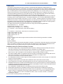
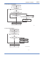
5.4
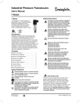
Setting of Tags and Addresses
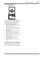
This section describes the steps in the procedure
to set the PD tags and node address in the
digitalYEWFLO. There are three states of Fieldbus
devices as shown in Figure 5.4, and if the state
is other than the lowest SM_OPERATIONAL
state, no function block is executed. Whenever
you have changed the PD tag or address of
a digitalYEWFLO, transfer its state to SM_
OPERATIONAL.
UNINITIALIZED
(No tag nor address is set)
FC100
F0502.ai
Figure 5.2
Macrocycle (Control Period)
Tag clear
Example of Loop Connecting Function
Blocks of Two digitalYEWFLOs with
Other Devices
Tag setting
INITIALIZED
(Only tag is set)
Address clear
Address setting
SM_OPERATIONAL
(Tag and address are retained, and
the function block can be executed.)
F0504.ai
Figure 5.4
Status Transition by Setting PD Tag and
Node Address
IM 01F06F00-01EN
5-4
<5. CONFIGURATION>
In each digitalYEWFLO, the PD tag and node
address are set to “FT1003” and 242 (hexadecimal
F2), respectively, before shipment from the factory
unless otherwise specified. To change only the
node address, clear the address once and then set
a new node address. To set the PD tag, first clear
the node address and clear the PD tag, then set the
PD tag and node address again.
Devices whose node address have been cleared
will await at the default address (randomly chosen
from a range of 248 to 251, or from hexadecimal
F8 to FB). At the same time, it is necessary
to specify the device ID in order to correctly
specify the device. The device ID of the YF100 is
5945430009xxxxxxxx. (The xxxxxxxx at the end
of the above device ID is a total of 8 alphanumeric
characters. Available characters are as follws.)
ABCDEF
0123456789
5.5
Communication Setting
To set the communication function, it is necessary
to change the database residing in SM (System
Management)-VFD.
5.5.1 VCR Setting
Set VCR (Virtual Communication Relationship),
which specifies the called party for communication
and resources. Each digitalYEWFLO has 33 VCRs
whose application can be changed, except for the
first VCR, which is used for management.
Each digitalYEWFLO has VCRs of four types:
Server (QUB) VCR
A server responds to requests from a host. This
communication needs data exchange. This type
of communication is called QUB (Queued Usertriggered Bidirectional) VCR.
Source (QUU) VCR
A source multicasts alarms or trends to other
devices. This type of communication is called
QUU (Queued User-triggered Unidirectional)
VCR.
Publisher (BNU) VCR
A publisher multicasts outputs of the AI blocks, DI
blocks, AR block, IT block and PID block to other
function blocks. This type of communication
is called BNU (Buffered Network-triggered
Unidirectional) VCR.
Subscriber (BNU) VCR
A subscriber receives output of another function
block(s) by AR block, IT block and PID block.
Each VCR has the parameters listed in Table 5.4.
Parameters must be changed together for each
VCR because modification for each parameter may
cause a contradiction.
IM 01F06F00-01EN
5-5
<5. CONFIGURATION>
Table 5.4
VCR Static Entry
SubParameter
index
1
FasArTypeAndRole
2
3
4
5
FasDllLocalAddr
FasDllConfigured
RemoteAddr
FasDllSDAP
FasDllMaxConfirm
DelayOnConnect
6
FasDllMaxConfirm
DelayOnData
7
FasDllMaxDlsduSize
8
9
10
11
12
13
Description
Indicates the type and role of
communication (VCR). The
following 4 types are used for
the digitalYEWFLO.
0x32: Server (Responds to
requests from host.)
0x44: Source (Transmits
alarm or trend.)
0x66: Publisher (Sends AI,
DI block output to other
blocks.)
0x76: Subscriber (Receives
output of other blocks by
PID block.)
Sets the local address
to specify a VCR in the
digitalYEWFLO. A range of 20
to F7 in hexadecimal.
Sets the node address of the
called party for communication
and the address (DLSAP or
DLCEP) used to specify VCR
in that address. For DLSAP
or DLCEP, a range of 20 to
F7 in hexadecimal is used.
Addresses in Subindex 2 and
3 need to be set to the same
contents of the VCR as the
called party (local and remote
are reversed).
Specifies the quality of
communication. Usually, one
of the following types is set.
0x2B: Server
0x01: Source (Alert)
0x03: Source (Trend)
0x91: Publisher/Subscriber
To establish connection for
communication, a maximum
wait time for the called party’s
response is set in ms. Typical
value is 60 seconds (60000).
For request of data, a
maximum wait time for the
called party’s response is
set in ms. Typical value is
60 secounds (60000).
SubParameter
index
14 FmsVfdId
15
16
17
FmsMaxOutstanding
ServiceCalling
FmsMaxOutstanding
ServiceCalled
FmsFeatures
Supported
Description
Sets VFD for the
digitalYEWFLO to be used.
0x1: System/network
management VFD
0x1234: Function block
VFD
Set 0 to Server. It is not used
for other applications.
Set 1 to Server. It is not used
for other applications.
Indicates the type of services
in the application layer. In
the digitalYEWFLO, it is
automatically set according to
specific applications.
These 33 VCRs are factory-set as shown in Table
5.5.
Table 5.5
VCR List
Index
(SM)
293
294
295
296
297
VCR
Number
1
2
3
4
5
298
299
6
7
300
301 to 325
8
9 to 33
Factory Setting
For system management (Fixed)
Server (LocalAddr = 0xF3)
Server (LocalAddr = 0xF4)
Server (LocalAddr = 0xF7)
Trend Source (LocalAddr = 0x07,
Remote Address=0x111)
Publisher (LocalAddr = 0x20)
Alert Source (LocalAddr = 0x07,
Remote Address=0x110)
Server (LocalAddr = 0xF9)
Not set
5.5.2 Function Block Execution Control
According to the instructions given in Section 5.3
“Function Block Link Definitions”, set the execution
cycle of the function blocks and schedule of
execution.
Specifies maximum DL
Service Data unit Size
(DLSDU). Set 256 for Server
and Trend VCR, and 64 for
other VCRs.
FasDllResidual
Specifies whether connection
ActivitySupported
is monitored. Set TRUE (0xff)
for Server. This parameter
is not used for other
communication.
FasDllTimelinessClass Not used for the
digitalYEWFLO.
FasDllPublisherTime
Not used for the
WindowSize
digitalYEWFLO.
FasDllPublisher
Not used for the
SynchronizaingDlcep
digitalYEWFLO.
FasDllSubscriberTime Not used for the
WindowSize
digitalYEWFLO.
FasDllSubscriber
Not used for the
SynchronizationDlcep digitalYEWFLO.
IM 01F06F00-01EN
5-6
<5. CONFIGURATION>
5.6
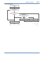
Block Setting
5.6.2 Trend Objects
Set the parameter for function block VFD.
5.6.1 Link Objects
A link object combines the data voluntarily
sent by the function block with the VCR. Each
digitalYEWFLO has 40 link objects. A single link
object specifies one combination. Each link object
has the parameters listed in Table 5.6. Parameters
must be changed together for each VCR because
the modifications made to each parameter may
cause inconsistent operation.
Table 5.6
Link Object Parameters
Subindex
1
LocalIndex
2
VcrNumber
3
RemoteIndex
4
ServiceOperation
5
StaleCountLimit
Parameters
Description
Sets the index of function block
parameters to be combined; set
“0” for Trend and Alert.
Sets the index of VCR to be
combined. If set to “0”, this link
object is not used.
Not used in the digitalYEWFLO.
Set to “0”.
Set one of the following. Set
only one each for link object for
Alert or Trend.
0: Undefined
2: Publisher
3: Subscriber
6: Alert
7: Trend
Set the maximum number of
consecutive stale input values
which may be received before
the input status is set to Bad. To
avoid the unnecessary mode
transition caused when the
data is not correctly received by
subscriber, set this parameter to
“2” or more.
Link objects are not factory-set. Set link objects as
shown in Table 5.7.
Table 5.7
Settings of Link Objects (example)
Index
30000
30001
30002
30003 to 30039
Link Object #
1
2
3
4 to 40
Settings(example)
VCR#6
AI. OUT
VCR#5
Trend
VCR#7
Alert
No used
It is possible to make settings so that a function
block automatically transmits the trend. For this,
each digitalYEWFLO has ten trend objects: eight
for trends of analog parameters and two for discrete
parameters. For each trend object, specify a single
parameter, the trend of which is to be transmitted.
Each trend object has the parameters listed in
Table 5.8. For the first four parameters, setting is
mandatory. Before writing parameter settings to
a trend object, parameter WRITE_LOCK of the
resource block must be modified to unlock the
write-lock.
Table 5.8
Subindex
1
Parameters for Trend Objects
Parameters
Description
Block Index
Sets the leading index of the
function block that takes a
trend.
2
Parameter Relative Sets the index of parameters
Index
taking a trend by a value relative
to the beginning of the function
block. In the digitalYEWFLO,
the following three types of
trends are possible.
7: PV
8: OUT
19: FIELD_VAL
3
Sample Type
Specifies how trends are taken.
Choose one of the following 2
types:
1: Sampled upon execution of
a function block.
2: The average value is
sampled.
4
Sample Interval
Specifies sampling intervals in
units of 1/32 ms. Set the integer
multiple of the function block
execution cycle.
5
Last Update
The last sampling time.
6 to 21 List of Status
Status part of a sampled
parameter.
21 to 37 List of Samples
Data part of a sampled
parameter.
Ten trend objects are not factory-set.
Table 5.9
Index
32000 to
32007
32008
32009
Trend Objects
Parameter
TREND_FLT.1 to
TREND_FLT.8
TREND_DIS.1
TREND_DIS.2
Factory Setting
Not set.
Not set (these parameters
are used with a DI block or
optional PID block).
IM 01F06F00-01EN
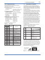
<5. CONFIGURATION>
System
Management
Information
Base (SMIB)
digital YEWFLO
Alert
FBOD
Trend
#1
Link object
#1
VCR
DI2
OUT
DI1
OUT
AI2 OUT
Resource Transducer
AI1 OUT
block
block
Network
Management
Information
Base (NMIB)
5-7
#2
#3
#4
#8
#3
#6
#7
DLSAP 0xF8 0xF3 0xF4 0xF7 0xF9 0x20
DLCEP
#2
#5
0x07
Fieldbus Cable
Host 1
Host 2
Device
F0505.ai
Figure 5.5
Example of Default Configuration
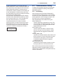
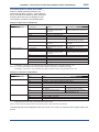
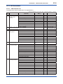
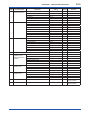
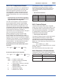
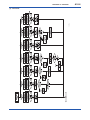
5.6.3 View Objects
View objects are used to group parameters.
This reduces the load of data transactions. Each
digitalYEWFLO supports four view objects for each
of the Resource block, Transducer block, three AI
blocks, two DI blocks, one IT block, one AR block,
and PID block (option /LC1). Each view object
contains a group of the parameters listed in Tables
5.11 to 5.17.
Table 5.10
VIEW_1
VIEW_2
VIEW_3
VIEW_4
Purpose of Each View Object
Description
Set of dynamic parameters required by operator for
plant operation. (PV, SV, OUT, Mode etc.)
Set of static parameters which need to be shown to
plant operator at once. (Range etc.)
Set of all the dynamic parameters.
Set of static parameters for configuration or
maintenance.
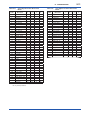
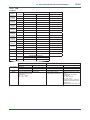
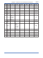
5.6.4 Function Block Parameters
Function block parameters can be read from the
host or can be set. For details of the function blocks,
refer to APPENDIX.
IM 01F06F00-01EN
5-8
<5. CONFIGURATION>
Table 5.11
Relative
Index
1
2
3
4
5
6
7
8
9
10
11
12
13
14
15
16
17
18
19
20
21
22
23
24
25
26
27
28
29
30
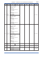
View Objects for Resource Block
Parameter
Mnemonic
ST_REV
TAG_DESC
STRATEGY
ALERT_KEY
MODE_BLK
BLOCK_ERR
RS_STATE
TEST_RW
DD_RESOURCE
MANUFAC_ID
DEV_TYPE
DEV_REV
DD_REV
GRANT_DENY
HARD_TYPES
RESTART
FEATURES
FEATURE_SEL
CYCLE_TYPE
CYCLE_SEL
MIN_CYCLE_T
MEMORY_SIZE
NV_CYCLE_T
FREE_SPACE
FREE_TIME
SHED_RCAS
SHED_ROUT
FAIL_SAFE
SET_FSAFE
CLR_FSAFE
VIEW_ VIEW_ VIEW_ VIEW_
1
2
3
4
2
2
2
2
2
1
4
2
1
4
2
1
4
2
1
1
2
2
2
2
1
2
4
2
4
4
4
4
4
4
1
1
Relative
Index
31
32
33
34
35
36
37
38
39
40
41
42
43
44
45
46
47
48
49
50
51
52
53
54
55
56
57
58
Parameter
VIEW_ VIEW_ VIEW_ VIEW_
Mnemonic
1
2
3
4
MAX_NOTIFY
4
LIM_NOTIFY
1
CONFIRM_TIME
4
WRITE_LOCK
1
UPDATE_EVT
BLOCK_ALM
ALARM_SUM
8
8
ACK_OPTION
2
WRITE_PRI
1
WRITE_ALM
ITK_VER
SOFT_REV
SOFT_DESC
SIM_ENABLE_MSG
DEVICE_STATUS_1
4
DEVICE_STATUS_2
4
DEVICE_STATUS_3
4
DEVICE_STATUS_4
4
DEVICE_STATUS_5
4
DEVICE_STATUS_6
4
DEVICE_STATUS_7
4
DEVICE_STATUS_8
4
SOFTDWN_PROTECT
1
SOFTDWN_FORMAT
1
SOFTDWN_COUNT
2
SOFTDWN_ACT_AREA
1
SOFTDWN_MOD_REV
16
SOFTDWN_ERROR
2
Total bytes
22
30
73
35
IM 01F06F00-01EN
5-9
<5. CONFIGURATION>
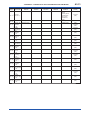
Table 5.12
Relative
Index
1
2
3
4
5
6
7
8
9
10
11
12
13
14
15
16
17
18
19
20
21
22
23
24
25
26
27
28
29
30
31
32
33
34
35
36
37
38
39
40
41
42
43
44
45
46
47
48
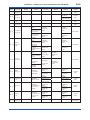
49
View Objects for Transducer Block
Parameter Mnemonic
ST_REV
TAG_DESC
STRATEGY
ALERT_KEY
MODE_BLK
BLOCK_ERR
UPDATE_EVT
BLOCK_ALM
TRANSDUCER_
DIRECTORY
TRANSDUCER_TYPE
XD_ERROR
COLLECTION_
DIRECTORY
PRIMARY_VALUE_TYPE
PRIMARY_VALUE
PRIMARY_VALUE_
RANGE
CAL_POINT_HI
CAL_POINT_LO
CAL_MIN_SPAN
CAL_UNIT
SENSOR_TYPE
SENSOR_RANGE
SENSOR_SN
SENSOR_CAL_METHOD
SENSOR_CAL_LOC
SENSOR_CAL_DATE
SENSOR_CAL_WHO
LIN_TYPE
SECONDARY_VALUE
SECONDARY_VALUE_
UNIT
PRIMARY_FTIME
TERTIARY_VALUE
TERTIARY_VALUE_UNIT
LIMSW_1_VALUE_D
LIMSW_1_TARGET
LIMSW_1_SETPOINT
LIMSW_1_ACT_
DIRECTION
LIMSW_1_HYSTERESIS
LIMSW_1_UNIT
LIMSW_2_VALUE_D
LIMSW_2_TARGET
LIMSW_2_SETPOINT
LIMSW_2_ACT_
DIRECTION
LIMSW_2_HYSTERESIS
LIMSW_2_UNIT
ALARM_PERFORM
ARITHMETIC_BLOCK
SENSOR_STATUS
FUNCTION
FLUID_TYPE
VIEW_1 VIEW_2
2
2
VIEW_3 VIEW_3 VIEW_3 VIEW_3 VIEW_4 VIEW_4 VIEW_4 VIEW_4 VIEW_4 VIEW_4
2nd
3rd
4th
1st
2nd
3rd
4th
5th
6th
1st
2
2
2
2
2
2
2
2
2
2
2
1
4
2
2
1
4
2
2
2
1
2
2
5
5
11
4
4
4
2
2
11
4
2
32
7
32
1
5
2
4
5
2
2
1
4
1
4
2
2
1
4
1
4
2
2
1
1
1
1
1
1
1
1
* Continued on next page
IM 01F06F00-01EN
5-10
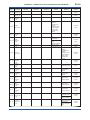
<5. CONFIGURATION>
Relative
Index
50
51
52
53
54
55
56
57
58
59
60
61
62
63
64
65
66
67
68
69
70
71
72
73
74
75
76
77
78
79
80
81
82
83
84
85
86
87
88
89
90
91
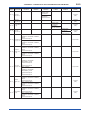
153
154
Parameter Mnemonic
VIEW_1 VIEW_2
TEMP_UNIT
PROCESS_TEMP
BASE_TEMP
DENSITY_UNIT
PROCESS_DENSITY
BASE_DENSITY
PRESSURE_UNIT
PROCESS_PRESSURE
BASE_PRESSURE
DEVIATION
SECONDARY_FTIME
CABLE_LENGTH
FIRST_TEMP_COEF
SECOND_TEMP_COEF
SIZE_SELECT
BODY_TYPE
VORTEX_SENSOR_
TYPE
K_FACTOR_UNIT
K_FACTOR
LOWCUT
UPPER_DISPLAY_MODE
LOWER_DISPLAY_MODE
DISPLAY_CYCLE
USER_ADJUST
REYNOLDS_ADJUST
VISCOSITY_VALUE
GAS_EXPANSION_FACT
FLOW_ADJUST
FLOW_ADJ_
FREQUENCY
FLOW_ADJ_DATA
TLA_VALUE
NOISE_BALANCE_MODE
NOISE_RATIO
SIGNAL_LEVEL
FLOW_VELOCITY
SPAN_VELOCITY
VORTEX_FREQ
SPAN_FREQ
FLUID_DENSITY
SENSOR_ERROR_
RECORD
MODEL
ALARM_SUM
VOLUME_FLOW
VOLUME_FLOW_UNIT
Total bytes
2
4
4
2
4
4
2
4
4
4
1
1
VIEW_3 VIEW_3 VIEW_3 VIEW_3 VIEW_4 VIEW_4 VIEW_4 VIEW_4 VIEW_4 VIEW_4
2nd
3rd
4th
1st
2nd
3rd
4th
5th
6th
1st
2
4
4
2
4
4
2
4
4
4
4
4
4
4
1
1
1
1
1
4
1
4
4
1
1
1
4
1
4
1
1
20
20
4
1
4
4
4
4
4
4
4
4
2
32
8
5
2
16
62
57
2
2
2
54
75
67
50
88
2
IM 01F06F00-01EN
5-11
<5. CONFIGURATION>
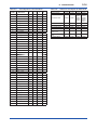
Table 5.13
Relative
Index
1
2
3
4
5
6
7
8
9
10
11
12
13
14
15
16
17
18
19
20
21
22
23
24
25
26
27
28
29
30
31
32
33
34
35
36
37
38
39
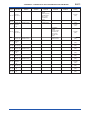
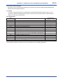
40
View Objects for Each AI Function
Block
Table 5.14
Parameter
VIEW_ VIEW_ VIEW_ VIEW_
Mnemonic
1
2
3
4
ST_REV
2
2
2
2
TAG_DESC
STRATEGY
2
ALERT_KEY
1
MODE_BLK
4
4
BLOCK_ERR
2
2
PV
5
5
OUT
5
5
SIMULATE
XD_SCALE
11
OUT_SCALE
11
GRANT_DENY
2
IO_OPTS
2
STATUS_OPTS
2
CHANNEL
2
L_TYPE
1
LOW_CUT
4
PV_FTIME
4
FIELD_VAL
5
5
UPDATE_EVT
BLOCK_ALM
ALARM_SUM
8
8
ACK_OPTION
2
ALARM_HYS
4
HI_HI_PRI
1
HI_HI_LIM
4
HI_PRI
1
HI_LIM
4
LO_PRI
1
LO_LIM
4
LO_LO_PRI
1
LO_LO_LIM
4
HI_HI_ALM
HI_ALM
LO_ALM
LO_LO_ALM
TOTAL
4
TOTAL_START
TOTAL_RATE_VAL
TOTAL_RESET
Total bytes
31
26
35
Relative
Index
1
2
3
4
5
6
7
8
9
10
11
12
13
14
15
16
17
18
19
20
21
22
23
24
View Objects for Each DI Function
Block
Parameter
Mnemonic
ST_REV
TAG_DESC
STRATEGY
ALERT_KEY
MODE_BLK
BLOCK_ERR
PV_D
OUT_D
SIMULATE_D
XD_STATE
OUT_STATE
GRANT_DENY
IO_OPTS
STATUS_OPTS
CHANNEL
PV_FTIME
FIELD_VAL_D
UPDATE_EVT
BLOCK_ALM
ALARM_SUM
ACK_OPTION
DISC_PRI
DISC_LIM
DISC_ALM
Total bytes
VIEW_ VIEW_ VIEW_ VIEW_
1
2
3
4
2
2
2
2
2
1
4
2
2
2
4
2
2
2
2
2
2
2
2
2
4
2
2
8
8
2
1
1
22
8
22
19
46
Note: AI2 and AI3 blocks do not have parameters after index
No. 37 (TOTAL) inclusive.
IM 01F06F00-01EN
5-12
<5. CONFIGURATION>
Table 5.15
Relative
Index
1
2
3
4
5
6
7
8
9
10
11
12
13
14
15
16
17
18
19
20
21
22
23
24
25
26
27
28
29
30
31
32
33
34
35
36
37
38
39
40
View Objects for PID Function Block (option /LC1)
Parameter
Mnemonic
ST_REV
TAG_DESC
STRATEGY
ALERT_KEY
MODE_BLK
BLOCK_ERR
PV
SP
OUT
PV_SCALE
OUT_SCALE
GRANT_DENY
CONTROL_OPTS
STATUS_OPTS
IN
PV_FTIME
BYPASS
CAS_IN
SP_RATE_DN
SP_RATE_UP
SP_HI_LIM
SP_LO_LIM
GAIN
RESET
BAL_TIME
RATE
BKCAL_IN
OUT_HI_LIM
OUT_LO_LIM
BKCAL_HYS
BKCAL_OUT
RCAS_IN
ROUT_IN
SHED_OPT
RCAS_OUT
ROUT_OUT
TRK_SCALE
TRK_IN_D
TRK_VAL
FF_VAL
VIEW_ VIEW_ VIEW_ VIEW_
1
2
3
4
2
2
2
2
2
1
4
2
5
5
5
4
2
5
5
5
11
11
2
2
2
5
4
1
5
5
4
4
4
4
4
4
4
4
Relative
Index
41
42
43
44
45
46
47
48
49
50
51
52
53
54
55
56
57
58
59
60
61
62
63
64
65
Parameter
Mnemonic
FF_SCALE
FF_GAIN
UPDATE_EVT
BLOCK_ALM
ALARM_SUM
ACK_OPTION
ALARM_HYS
HI_HI_PRI
HI_HI_LIM
HI_PRI
HI_LIM
LO_PRI
LO_LIM
LO_LO_PRI
LO_LO_LIM
DV_HI_PRI
DV_HI_LIM
DV_LO_PRI
DV_LO_LIM
HI_HI_ALM
HI_ALM
LO_ALM
LO_LO_ALM
DV_HI_ALM
DV_LO_ALM
Total bytes
5
VIEW_ VIEW_ VIEW_ VIEW_
1
2
3
4
11
4
8
8
2
4
1
4
1
4
1
4
1
4
1
4
1
4
43
43
83
104
4
4
4
5
5
5
1
5
5
11
2
5
2
5
5
IM 01F06F00-01EN
5-13
<5. CONFIGURATION>
Table 5.16
Relative
Index
View Objects for Enhanced Arithmetic (AR) Block
Parameter
Mnemonic
VIEW_ VIEW_ VIEW_ VIEW_
1
2
3
4
2
2
2
2
30
Parameter
Mnemonic
BAL_TIME
31
BIAS
32
GAIN
4
33
OUT_HI_LIM
4
34
OUT_LO_LIM
4
35
UPDATE_EVT
36
BLOCK_ALM
37
AR_VOLUME_
FLOW_UNIT
2
11
38
AR_TEMP_UNIT
2
11
39
AR_BASE_TEMP
4
40
AR_PRESSURE_
UNIT
2
5
41
AR_BASE_
PRESSURE
4
42
AR_DEVIATION
4
43
AR_DENSITY_
UNIT
2
44
AR_BASE_
DENSITY
4
45
AR_FIRST_TEMP_
COEF
4
46
AR_SECOND_
TEMP_COEF
4
47
AR_FLOW_
CONFIG
48
AR_DENSITY_
FACTOR
49
AR_DENSITY_
FACTOR_UNIT
50
AR_CONFIG_
SOFT_REV
51
AR_CONFIG_DATE
52
AR_CONFIG_WHO
53
AR_CONFIG_
STATUS
54
AR_CONFIG_
VSTRING32
55
AR_CONFIG_
VSTRING16
56
AR_CONFIG_
OSTRING32
57
AR_CONFIG_
OSTRING2
1
ST_REV
2
TAG_DESC
3
STRATEGY
2
4
ALERT_KEY
1
5
MODE_BLK
4
4
6
BLOCK_ERR
2
2
7
PV
5
5
8
OUT
5
5
9
PRE_OUT
5
5
10
PV_SCALE
11
OUT_RANGE
12
GRANT_DENY
13
INPUT_OPTS
14
IN
15
IN_LO
5
16
IN_1
5
17
IN_2
5
18
IN_3
5
19
RANGE_HI
4
20
RANGE_LO
4
21
BIAS_IN_1
4
22
GAIN_IN_1
4
23
BIAS_IN_2
4
24
BIAS_IN_2
4
25
BIAS_IN_3
4
26
BIAS_IN_3
4
27
COMP_HI_LIM
4
28
COMP_LO_LIM
4
29
ARITH_TYPE
1
2
Relative
Index
2
Total bytes
VIEW_ VIEW_ VIEW_ VIEW_
1
2
3
4
4
4
5
2
23
26
53
102
IM 01F06F00-01EN
5-14
<5. CONFIGURATION>
Table 5.17
Relative
Index
Table 5.18
View Objects for IT Function Block
Parameter
Mnemonic
VIEW_ VIEW_ VIEW_ VIEW_
1
2
3
4
1
ST_REV
2
TAG_DESC
3
STRATEGY
4
ALERT_KEY
5
MODE_BLK
4
4
6
BLOCK_ERR
2
2
7
TOTAL_SP
4
4
8
OUT
5
9
OUT_RANGE
11
10
GRANT_DENY
2
11
STATUS_OPTS
12
IN_1
5
5
13
IN_2
5
5
14
OUT_TRIP
2
2
15
OUT_PTRIP
2
2
16
TIME_UNIT1
1
17
TIME_UNIT2
1
18
UNIT_CONV
4
19
PULSE_VAL1
4
20
PULSE_VAL2
21
REV_FLOW1
2
2
22
REV_FLOW2
2
2
23
RESET_IN
2
2
24
STOTAL
25
RTOTAL
26
SRTOTAL
4
27
SSP
4
28
INTEG_TYPE
1
29
INTEG_OPTS
2
30
CLOCK_PER
4
31
PRE_TRIP
4
32
N_RESET
4
4
33
PCT_INCL
4
4
34
GOOD_LIM
35
UNCERT_LIM
36
OP_CMD_INT
37
OUTAGE_LIM
38
RESET_CONFIRM
39
UPDATE_EVT
40
BLOCK_ALM
41
ACCUM_TOTAL
Total bytes
2
2
2
Indexes to View Objects for Each Block
Block
Resource block
2
2
Transducer block
1
5
2
AI1 function block
AI2 function block
DI1 function block
DI2 function block
PID function block
(option /LCI)
Enhanced Arithmetic
block
IT function block
VIEW_1 VIEW_2 VIEW_3 VIEW_4
40100
40101
40102
40103
40206
40202
40207
40203
40208
40200
40201
40204
40209
40205
40210
40211
40400
40401
40402
40403
40410
40411
40412
40413
40600
40601
40602
40603
40610
40611
40612
40613
40800
40801
40802
40803
41750
41751
41752
41753
41600
41601
41602
41603
4
4
4
4
4
4
1
1
2
2
4
4
52
17
68
42
IM 01F06F00-01EN
6-1
<6. EXPLANATION OF BASIC ITEMS>
6.
EXPLANATION OF BASIC ITEMS
This chapter describes basic TR (Transducer
block), AI, and DI function block parameter setting,
displays of the integral indicator. For detailes of the
function blocks, refer to APPENDIX.
This chapter contains information on how to adapt
the function and performance of the digitalYEWFLO
to suit specific applications. Because two or more
devices are connected to FOUNDATION Fieldbus,
settings including the requirements of all devices
need to be determined. Practically, the following
steps must be taken.
The following section describes each step of the
procedure in the order given. Using a dedicated
configuration tool allows the procedure to be
significantly simplified. This section describes the
procedure which has relatively simple functions.
6.1 Setting and Changing
Parameters for the Whole
Process
IMPORTANT
Do not turn off the power immediately after
setting. When the parameters are saved to the
EEPROM, the redundant processing is executed
for an improvement of reliability. If the power
is turned off within 60 seconds after setting is
made, the modified parameters are not saved
and the setting may return to the original values.
Block mode
Many parameters require a change of the block
mode of the function block to O/S (Out of Service)
when their data is changed. To change the block
mode of the function block, its MODE_BLK needs
to be changed. The MODE_BLK is comprised of
four sub-parameters below.
(1) Target (Target mode):
Sets the operating condition of the block.
(2) Actual (Actual mode):
Indicates the current operating condition.
(3) Permit (Permitted mode):
Indicates the operating condition that the block
is allowed to take.
(4) Normal (Normal mode):
Indicates the operating condition that the block
will usually take.
IM 01F06F00-01EN
6-2
<6. EXPLANATION OF BASIC ITEMS>
6.2 Transducer Block Parameters
The transducer block sets functions specific to the
flow rate measurement of the digitalYEWFLO. For
each block parameter in digitalYEWFLO, refer
to APPENDIX 1 “LIST OF PARAMETERS FOR
EACH BLOCK OF digitalYEWFLO.” The following
describes important parameters and how to set
them.
For the METHOD of TR block, refer to APPENDIX
10.1 “Transducer Block”.
Operation Conditions
Relative Index
Table 6.1
After setting parameters of the transducer block,
set up XD_SCALE of the AI1 block (and of the
AI2 block as appropriate).
Table 6.1 shows the parameters that must be
set (in order of the relative index sequentially)
depending on the operation conditions.
Mandatory Parameter Setting for Transducer Block Depending on Operation Conditions
Parameter
Name
47
SENSOR_
STATUS
48
THERMOMETER_
FUNCTION
49 FLUID_TYPE
1=
Standard
—
1=
Standard
—
2 = Built-in
Temp.
Sensor
1 = Monitor
only; or
6 = Not use
1 = LIQUID:
Volume;
1 = LIQUID:
Volume;
2=
GAS/
STEAM:
Volume;
2=
GAS/
STEAM:
Volume;
3=
LIQUID:
Mass or
5 = GAS:
STD/Normal 3 =
LIQUID:
Mass or
4=
GAS/
STEAM:
Mass
4=
GAS/
STEAM:
Mass
2 = Built-in
Temp.
Sensor
1 = Monitor
only; or
6 = Not use
2 = Built-in
Temp.
Sensor
2=
Saturated
steam
2 = Built-in
Temp.
Sensor
3=
Superheat
steam
2 = Built-in
Temp.
Sensor
4 = GAS:
STD/Normal
2 = Built-in
Temp.
Sensor
5 = LIQUID:
Mass
5 = GAS:
STD/Normal
—
—
—
—
TEMPERATURE_
UNIT
51 PROCESS_TEMP
50
53 DENSITY_UNIT
PROCESS_
54
DENSITY
52 BASE_TEMP
Mandatory
(1) Mandatory Parameter Setting for
Transducer Block
55 BASE_DENSITY
PRESSURE_
56
UNIT
PROCESS_
57
PRESSURE
BASE_
58
PRESSURE
59 DEVIATION
FIRST_TEMP_
62
COEF
SECOND_TEMP_
63
COEF
IM 01F06F00-01EN
<6. EXPLANATION OF BASIC ITEMS>
(2) Explanations of Parameters
1) PRIMARY_VALUE_TYPE (Relative Index 13)
Indicates the type of the measured item
represented by PRIMARY_VALUE. For the
digitalYEWFLO, the value of PRIMARY_
VALUE_TYPE is 100 and 101 as follows:
100 = Mass flow
101 = Volumetric flow
65535 = Other
Default: 101 (Volumetric flow)
2) PRIMARY_VALUE_FTIME (Relative Index 30)
Defines the damping time constant for
the flow rate to be input to the flow rate
calculation.
Setting range: 0 to 99 (seconds)
Default: 4 (seconds)
3) THERMOMETER_FUNCTION (Relative Index 48)
Determines the use of the temperature
monitoring function for a model with the MV
option.
1 = Monitor only
2 = Saturated steam
3 = Superheat steam
4 = Gas: STD/Normal
5 = LIQUID: Mass
6 = Not use
Default: 1 (= Monitor only)
4) FLUID_TYPE (Relative Index 49)
Selects the type of process fluid to be
measured.
1 = LIQUID: Volume
2 = Gas/Steam: Volume
3 = LIQUID: Mass
4 = Gas/Steam: Mass
5 = Gas: Std/Normal
Default: 1 (= LIQUID: Volume)
5) TEMPERATURE_UNIT (Relative Index 50)
Selects the unit of temperature.
Setting range: 1001 (= C), 1002 (= F)
Default: 1001 (= C)
6) PROCESS_TEMP (Relative Index 51)
Sets the normal operating temperature.
Setting range: -999.9 to 999.9
Unit: As selected in TEMP_UNIT
Default: 15.0
7) BASE_TEMP (Relative Index 52)
Sets the temperature under the standard
conditions.
Setting range: -999.9 to 999.9
Unit: As selected in TEMP_UNIT
Default: 15.0
6-3
8) DENSITY_UNIT (Relative Index 53)
Selects the unit of density.
Setting range: 1097 (=kg/m3)
Default: 1097 (= kg/m3)
9) PROCESS_DENSITY (Relative Index 54)
Selects the density under the normal
operating conditions.
Setting range: 0.00001 to 32000
Unit: As selected in DENSITY_UNIT
Default: 1024.0
10) BASE_DENSITY (Relative Index 55)
Sets the density under the standard
conditions.
Setting range: 0.00001 to 32000
Unit: As selected in DENSITY_UNIT
Default: 1024.0
11) PRESSURE_UNIT (Relative Index 56)
Selects the unit of pressure.
Setting range: 1545 (= MPaa) or 1547 (= kPaa)
Default: 1545 (= MPaa)
12) PROCESS_PRESSURE (Relative Index 57)
Sets the absolute pressure under the normal
operating conditions.
Setting range: 0.00001 to 32000
Unit: As selected in PRESSURE_UNIT
Default: 0.1013
13) BASE_PRESSURE (Relative Index 58)
Sets the absolute pressure under the
standard conditions.
Setting range: 0.00001 to 32000
Unit: As selected in PRESSURE_UNIT
Default: 0.1013
14) DEVIATION (Relative Index 59)
Sets the deviation factor of the process fluid.
Setting range: 0.001 to 10.0
Default: 1.0 (nondimensional number)
15) SECONDARY_VALUE_FTIME (Relative Index 60)
Sets the damping factor for temperature
measurement (for a model with the MV
option).
Setting range: 0 to 99
Unit: s (seconds)
Default: 4 (seconds)
16) SIZE_SELECT (Relative Index 64)
Selects the flowmeter size.
Setting range:
1 = 15 mm (1/2 in.) 2 = 25 mm (1 in.)
3 = 40 mm (1.5 in.) 4 = 50 mm (2 in.)
5 = 80 mm (3 in.)
6 = 100 mm (4 in.)
7 = 150 mm (6 in.) 8 = 200 mm (8 in.)
9 = 250 mm (10 in.) 10 = 300 mm (12 in.)
11 = 400 mm (16 in.)
Default: 2 (= 25 mm (1 in.))
IM 01F06F00-01EN
<6. EXPLANATION OF BASIC ITEMS>
17) K_FACTOR_UNIT (Relative Index 67)
Selects the unit of the K factor.
Setting range: 1 (=p/L)
Default: 1 (=p/L).
18) K_FACTOR (Relative Index 68)
Sets the K factor of the combined detector at
15C.
Setting range: 0.00001 to 32000
Unit: As selected in K_FACTOR_UNIT
Default: 68.6
19) LOW_CUT_FLOW (Relative Index 69)
Sets the low cutoff flow rate level.
Setting range: Minimum flow rate × 0.5 to
XD_SCALE.EU_100
Unit: As selected in PRIMARY_VALUE_
RANGE.Units Index
Default: Minimum gas flow rate for the size of
25 mm (1 in.)
20) UPPER_DISPLAY_MODE (Relative Index 70)
Selects the data to be displayed on the upper
row of the LCD indicator, as follows:
1 = Flow Rate (%): Instantaneous flow rate
as a percentage
2 = Flow Rate: Instantaneous flow rate in
the specified unit
3 = Temperature (%): Temperature as a
percentage (can only be selected for a
model with the option /MV)
4 = Arithmetic Out: Output of AR block
21) LOWER_DISPLAY_MODE (Relative Index 71)
Selects the data to be displayed on the upper
row of the LCD indicator, as follows:
1 = Blank
2 = Total: Totalized flow rate
3 = Temperature: Temperature (can only be
selected for a model with the MV option)
4 = Integrator Out: Output of IT block
22) DISPLAY_CYCLE (Relative Index 72)
Sets the display refresh cycle of the LCD
indicator, as a multiple of 500 milliseconds.
Setting range: 1 to 10 (= 500 ms to 5 s)
Default: 1 (= 500 ms)
6-4
6.3 AI Function Block Parameters
Parameters of the three AI function blocks can be
read and written from the host.
AI1: Flow rate, AI2: Temperature, AI3: Volumetric
flow rate for the use of mass flow rate calculation
at AR function block. For each block parameter
in digitalYEWFLO, refer to APPENDIX 1 “LIST
OF PARAMETERS FOR EACH BLOCK OF
digitalYEWFLO.” The following describes important
parameters and how to set them.
MODE_BLK:
Indicates the three types of function block
modes; Out_Of_Service, Manual, and Auto.
In Out_Of_Service mode, the AI block does
not operate. The Manual mode does not allow
values to be updated. The Auto mode causes the
measured value to be updated. Under normal
circumstances, set the Auto mode to take effect.
The Auto mode is the factory default.
CHANNEL:
This is the parameter of the transducer block to
be input to the AI block. AI1 block is assigned
flow rate. AI2 block is assigned temperature.
AI3 block is assigned volumetric flow rate for AR
block.
This setting can not be changed.
XD_SCALE:
Scale of input from the transducer block. The
maximum flow rate range in the registered
sizing data is setting. “0” (0%), “10.000” (100%),
and “m3/h” for the unit are factory-set in case
of UNCALIBRATION order. Changing the unit
(can be set only in flow rate) also causes the unit
within the transducer block to be automatically
changed. (The unit is automatically changed
according to the unit selected by AI1, AI2.) Units
which can be set by XD_SCALE are shown in
Table 6.2.
The setting range of the 100% scale (XD_
SCALE.EU at 100) depends on the unit setting
(XD_SCALE.Units Index) as shown in Table 6.3.
IM 01F06F00-01EN
6-5
<6. EXPLANATION OF BASIC ITEMS>
Table 6.2
Item
Available Units
Available Units
kg/s (1322), kg/min (1323),
LIQUID:
kg/h (1324), kg/d (1325),
Mass
t/s (1326), t/min (1327), t/h
(1328), t/d (1329), lb/s (1330),
GAS/STEAM:
lb/min (1331), lb/h (1332),
Mass
lb/d (1333)
m3/s (1347), m3/min (1348),
m3/h (1349), m3/d (1350),
L/s (1351), L/min (1352),
L/h (1353), L/d (1354), CFS
[cf/s] (1356), CFM [cf/min]
(1357), CFH [cf/h] (1358),
ft3/d [cf/d] (1359), gal/s
LIQUID:
[USgal/s] (1362), GPM
Volume
[USgal/min] (1363), gal/h
GAS/STEAM: [USgal/h] (1364), gal/d
AI1
[USgal/d] (1365), ImpGal/s
Volume
(channel 1)
[UKgal/s] (1367), ImpGal/min
[UKgal/min] (1368), ImpGal/h
[UKgal/h] (1369), ImpGal/d
[UKgal/d] (1370), bbl/s
(1371), bbl/min (1372), bbl/h
(1373), bbl/d (1374)
SCFM [scf/min] (1360),
SCFH [scf/h] (1361), Nm3/s
(1522), Nm3/min (1523),
XD_
Nm3/h (1524), Nm3/d (1525)
GAS
SCALE
Sm3/s (1527), Sm3/min
Std/Normal
(1528), Sm3/h (1529), Sm3/d
(1530), NL/s (1532), NL/min
N: Normal
S: Standard (1533), NL/h (1534), NL/d
(1535), SL/s (1537), SL/min
(1538), SL/h (1539), SL/d
(1540)
AI2
Temperature °C (1001), °F (1002)
(channel 2)
m3/s (1347), m3/min (1348),
m3/h (1349), m3/d (1350),
L/s (1351), L/min (1352),
L/h (1353), L/d (1354), CFS
[cf/s] (1356), CFM [cf/min]
(1357), CFH [cf/h] (1358),
ft3/d [cf/d] (1359), gal/s
[USgal/s] (1362), GPM
AI3
–
[USgal/min] (1363), gal/h
(channel 5)
[USgal/h] (1364), gal/d
[USgal/d] (1365), ImpGal/s
[UKgal/s] (1367), ImpGal/min
[UKgal/min] (1368), ImpGal/h
[UKgal/h] (1369), ImpGal/d
[UKgal/d] (1370), bbl/s
(1371), bbl/min (1372), bbl/h
(1373), bbl/d (1374)
Table 6.3
Block
Setting Range of EU at 100 of XD_
SCALE Depending on Unit
Block
Unit Selected
AI1 Refer to Table 6.2
AI2 °C
°F
AI3 Refer to Table 6.2
Setting Range of EU at 100
above 0.0
–273.15 to 999.9
–459.67 to 999.9
above 0.0
OUT_SCALE:
Sets the range of output (from 0% to 100%).
Available units for OUT_SCALE are the same
as units for XD_SCALE in Table 6.2 and
percentage.
L_TYPE:
Specifies the operation function of the AI1 block.
The factory default is “Direct”, so the input
delivered to CHANNEL is directly reflected on
OUT. If set to “Indirect”, scaling by XD_SCALE
and OUT_SCALE is carried out and is reflected
on OUT. “Indirect SQRT” is not used for a
digitalYEWFLO.
PV_FTIME:
Sets the time constant of the damping function
within AI block (primary delay) in seconds.
Alarm Priority:
Indicates the priority of the process alarm.
If a value of 3 or greater is set, an alarm is
transmitted. The factory default is 0. Four types
of alarm can be set: HI_PRI, HI_HI_PRI, LO_
PRI, and LO_LO_PRI.
Alarm Threshold:
Sets the threshold at which a process alarm is
generated. The factory default setting is a value
that does not generate an alarm. Four types of
alarm can be set: HI_LIM, HI_HI_LIM, LO_LIM,
and LO_LO_LIM.
Note: With the same setting, some units are represented
differently between the FOUNDATION Fieldbus
communication type and the HART or BRAIN
communication type of a digitalYEWFLO. Each unit
enclosed in brackets above shows the unit for the HART
or BRAIN communication type of a digitalYEWFLO,
corresponding to the preceding unit (for the FOUNDATION
Fieldbus communication type).
IM 01F06F00-01EN
6-6
<6. EXPLANATION OF BASIC ITEMS>
6.4 Parameters of DI Function
Block
6.5
DI function blocks work based on the limit switch
signals generated by the transducer block where
DI1 is based on those signals on the flow rate and
DI2 on the temperature (with the option /MV).
Table 6.5
MODE_BLK
Supports O/S, Auto, and Manual modes. The DI
block does not function in the O/S mode, does not
update the measured value in the Manual mode,
and updates the measured value in the Auto
mode. Normally, set the mode to Auto. Before the
digitalYEWFLO is shipped from the factory, all the
DI blocks are set to O/S mode.
CHANNEL
Selects the input to the DI block from the
transducer. CHANNEL is always set to 3 or 4 for a
digitalYEWFLO.
PV_FTIME
Stipulates the delay time (in seconds) of changing
the output value after a change of the value inside
the DI block.
DISC_PRI
Determines the priority level of the discrete alarm
on the block’s output (OUT_D). The alarm will
be transmitted upon occurrence only when the
DISC_PRI is set at 3 or higher. This parameter is
set to 1 before the digitalYEWFLO is shipped from
the factory.
Table 6.4
Value
0
1
3 to 7
8 to 15
Alarm Priority
Descriptions
Alart is not notified. Alarm parameters are not updated.
Alart is not notified.
Advisory alarms.
Critical alarms.
DISC_LIM
Setpoint of the discrete alarm; when the value of
OUT_D agrees with the value set in DISC_LIM, the
discrete alarm is generated
Integral LCD Indicator
The display items are as follows.
Display Items
Display Items Upper Display Mode
AI1
Flowrate%
Flowrate
AI2
Temperature%
AR
Arithmetic OUT
Lower Display Mode
Blank
AI1
Total
AI2
Temperature
IT
Integrator OUT
The display items can be made by selecting in
Upper/Lower Display mode.
The contents of each display items are as follows.
(1)Flowrate%, Temperature%
(2)Flowrate
(3)Total
(4)Temperature
(5)Arithmetic OUT
Display Value=Display AR OUT Vale.
(by setting AROUT_RANG)
Display unit=Display the setting value of AR
OUT_RANGE. Units Index.
Available display units are as follows.
Volumetric Flow Rate
m3/s(1347), m3/min(1348), m3/h(1349),
m3/d(1350), L/s(1351), L/min(1352),
L/h(1353), L/d(1354), CFS(1356), CFM(1357),
CFH(1358), ft3/d(1359), gal/s(1362), GPM(1363),
gal/h(1364), gal/d(1365), ImpGal/s(1367),
ImpGal/min(1368), ImpGal/h(1369),
ImpGal/d(1370), bbl/s(1371), bbl/min(1372),
bbl/h(1373), bbl/d(1374)
Mass Flow Rate
kg/s(1322), kg/min(1323), kg/h(1324),
kg/d(1325), t/s(1326), t/min(1327), t/h(1328),
t/d(1329), lb/s(1330), lb/min(1331), lb/h(1332),
lb/d(1333)
IM 01F06F00-01EN
<6. EXPLANATION OF BASIC ITEMS>
6-7
Voluemetric Flow Rate at Normal Condition
Nm3/s(1522), Nm3/m(1523), Nm3/h(1524),
Nm3/d(1525), NL/s(1532), NL/m(1533),
NL/h(1534), NL/d(1535), Sm3/s(1527),
Sm3/m(1528), Sm3/h(1529), Sm3/d(1530),
SL/s(1537), SL/m(1538), SL/h(1539),
SL/d(1540), SCFM(1360), SCFH(1361)
N: Normal, S: Standard.
Percentage
%(1342)
(1) Display Style
In case of plus display
Example : AR OUT_RANGE. EU_100 : 1
Example : AR OUT_RANGE. EU_100 : 0.00001
In case of Minus display
Example : AR OUT_RANGE. EU_100 : 1,000
AR OUT_RANGE. EU_100 : 100,000
(2) Alarm Display
In case of plus display
Example : Display“99999” and “AL - 61” altrnatelly
In case of Minus display
Example : AR OUT_RANGE. EU_100 : 1,000
AR OUT_RANGE. EU_100 : 100,000
IM 01F06F00-01EN
<7. IN-PROCESS OPERATION>
7.
IN-PROCESS OPERATION
This chapter describes the procedure performed
when changing the operation of the function block
of the digitalYEWFLO in process.
7.1
Mode Transition
When the function block mode is changed to Out_
Of_Service, the function block pauses and a block
alarm is issued.
When the function block mode is changed to
Manual, the function block suspends updating of
output values. In this case alone, it is possible to
write a value to the OUT parameter of the block
for output. Note that no parameter status can be
changed.
7.2
7-1
The error details corresponding to alarm indications
on the LCD indicator and whether or not switches
are provided to disable the corresponding alarms
are shown in Table 7.1. For the alarms for which an
alarm mask switch is provided, the default alarm
settings are also shown. Those alarms for which
an alarm mask switch is not provided are enabled
at all times. For how to modify these mask switch
statuses, refer to APPENDIX 3 “OPERATION OF
EACH PARAMETER IN FAILURE MODE.”
Generation of Alarm
7.2.1 Indication of Alarm
When the self-diagnostics function indicates that a
device is faulty, an alarm (device alarm) is issued
from the resource block. When an error (block
error) is detected in each function block or an error
in the process value (process alarm) is detected, an
alarm is issued from each block. If an LCD indicator
is installed, the error number is displayed as ALXX. If two or more alarms are issued, multiple error
numbers are displayed in 2-second intervals. (when
“1” is set to DISPLAY_CYCLE).
F0701.ai
Figure 7.1
Error Identification on Indicator
IM 01F06F00-01EN
<7. IN-PROCESS OPERATION>
Table 7.1
LCD
7-2
Alarm Indications and Alarm Mask Switches
Error Detail
Alarm Mask
SW (default)
AL-01
The EEPROM(S) failed.
Not provided
AL-02
The serial communication circuit in the
amplifier failed (type 1 error).
Not provided
AL-03
The serial communication circuit in the
amplifier failed (type 2 error).
Not provided
AL-04
The EEPROM(F) failed.
Not provided
AL-05
The flow sensor failed.
Provided (ON)
AL-06
The input circuit in the amplifier failed.
Provided (ON) *
AL-07
The temperature circuit in the amplifier failed.
Not provided
AL-08
The temperature sensor failed.
Not provided
AL-20
No function blocks are scheduled.
Not provided
AL-21
Resource Block is in O/S mode.
Not provided
AL-22
Transducer Block is in O/S mode.
Not provided
AL-23
AI1 Block is in O/S mode.
Provided (ON)
AL-24
AI2 Block is in O/S mode.
Provided (OFF)
AL-25
DI1 Block is in O/S mode.
Provided (OFF)
AL-26
DI2 Block is in O/S mode.
Provided (OFF)
AL-27
PID Block is in O/S mode.
Provided (OFF)
AL-28
AI3 Block is in O/S mode.
Provided (OFF)
AL-29
IT Block is in O/S mode.
Provided (OFF)
AL-30
AR Block is in O/S mode.
Provided (OFF)
AL-41
Flow rate is over the range.
Not provided
AL-42
The flow rate span setting exceeds the range
limit.
Not provided
AL-43
Temperature is over the range. (Regulated in
the upper or lower limit value)
Not provided
AL-51
The transient vibration makes the current flow Provided (OFF)
rate output constant.
AL-52
The high vibration makes the current flow rate Provided (OFF)
output zero.
AL-53
The shedder bar is clogged with a material.
Provided (OFF)
AL-54
The current flow rate is fluctuating more than
20%.
Provided (OFF)
AL-61
Indicator is over the range.
Not provided
AL-62
AI1 Block is in Manual mode.
Provided (ON)
AL-63
AI1 Block is in simulation mode.
Provided (ON)
AL-64
AI1 Block is not scheduled.
Provided (ON)
AL-65
AI2 Block is in Manual mode.
Provided (OFF)
AL-66
AI2 Block is in simulation mode.
Provided (OFF)
AL-67
AI2 Block is not scheduled.
Provided (OFF)
AL-68
DI1 Block is in Manual mode.
Provided (OFF)
AL-69
DI1 Block is in simulation mode.
Provided (OFF)
AL-70
DI1 Block is not scheduled.
Provided (OFF)
AL-71
DI2 Block is in Manual mode.
Provided (OFF)
AL-72
DI2 Block is in simulation mode.
Provided (OFF)
AL-73
DI2 Block is not scheduled.
Provided (OFF)
AL-74
PID Block is in Bypass mode.
Provided (OFF)
AL-75
PID Block is failed (type 1 error).
Provided (OFF)
AL-76
PID Block is failed (type 2 error).
Provided (OFF)
AL-77
AI3 Block is in Manual mode.
Provided (OFF)
AL-78
AI3 Block is in simulation mode.
Provided (OFF)
AL-79
AI3 Block is not scheduled.
Provided (OFF)
AL-80
IT Block is in Manual mode.
Provided (OFF)
AL-81
IT Block is not scheduled.
Provided (OFF)
AL-82
IT Total backup failed. Last IT Output.Value (IT. Provided (OFF)
OUT.Value) could not saved.
IT Clock Period (IT.CLOCK_PER) is smaller
than IT Period of Execution(IT.EXECUTION_
PERIOD).
Provided (OFF)
AL-83
AL-84
AR Block is in Manual mode.
Provided (OFF)
AL-85
AR Block is not scheduled.
Provided (OFF)
LCD
Error Detail
Alarm Mask
SW (default)
AL-86
AR Range High (AR.RANGE_HI) is smaller
than AR Range Low (AR.RANGE_LOW).
Provided (OFF)
AL-87
AR Input1 (AR.IN_1) is over range.
Provided (OFF)
AL-88
AR Input2 (AR.IN_2) is over range.
Provided (OFF)
AL-89
AR Input (AR.IN) is not connected to the
volumetric flow.
Provided (OFF)
AL-90
AR Input1 (AR.IN_1) is not connected to the
temperature.
Provided (OFF)
AL-91
AR Input2 (AR.IN_2) is not connected to the
pressure.
Provided (OFF)
Provided (OFF)
AL-92
AR Compensation Coefficient (AR.
AR_FLOW_CONFIG.Element) changed
unexpected.
Therefore AR Output (AR.OUT.Value) is
uncertainty.
AR Output Range .Units Index (AR.OUT_
RANGE.Unit Index) is not selected rightly the
corresponding to AR Arithmetic Type (AR.
ARITH_TYPE).
Provided (OFF)
AL-93
*: Not provided for a model with the option /MV and with the fluid
density calculation set to be active.
IM 01F06F00-01EN
7-3
<7. IN-PROCESS OPERATION>
7.2.2 Alarms and Events
7.3
Each digitalYEWFLO can report the following
alarms and events as alerts.
Analog Alerts (Generated when a process value
exceeds threshold)
By AI Block:
Hi-Hi Alarm, Hi Alarm, Low
Alarm, Low-Low Alarm
Discrete Alerts (Generated when an abnormal
condition is detected)
By Resource Block: Block Alarm, Write Alarm
By Transducer Block: Block Alarm
By AI Block:
Block Alarm
By PID Block:
Block Alarm
Update Alerts (Generated when a important
(restorable) parameter is updated)
By Resource Block: Update Event
By Transducer Block: Update Event
By AI Block:
Update Event
By PID Block:
Update Event
The simulation function simulates the input of a
function block and lets it operate as if the data was
received from the transducer block. It is possible to
conduct testing for the downstream function blocks
or alarm processes.
A SIMULATE_ENABLE jumper switch is mounted
on the digitalYEWFLO’s amplifier. This is to prevent
the accidental operation of this function. When
this is switched on, simulation is enabled. (Refer
to Figure 7.2.) To initiate the same action from a
remote terminal, if REMOTE LOOP TEST SWITCH
is written to SIM_ENABLE_MSG (index 1044)
parameter of the resource block, the resulting action
is the same as is taken when the above switch is
on. Note that this parameter value is lost when the
power is turned off. In simulation enabled status,
an alarm is generated from the resource block, and
other device alarms will be masked; for this reason
the simulation must be disabled immediately after
using this function.
The SIMULATE parameter of AI block consists of
the elements listed in Table 7.3 below.
An alert has the following structure:
Table 7.2
Alert Object
Analog
Alert
Discrete
Alert
Update
Alert
Subindex
1
1
1
2
2
2
3
3
3
4
4
4
5
5
5
6
6
6
7
7
7
8
8
9
9
10
10
8
11
11
9
Parameter
Name
Explanation
Index of block from which
Block Index
alert is generated
Alert Key copied from the
Alert Key
block
Standard
Type of the alert
Type
Alert Name identified by
Mfr Type
manufacturer specific DD
Message
Reason of alert
Type
notification
Priority
Priority of the alarm
Time when this alert is first
Time Stamp
detected
Enumerated cause of this
Subcode
alert
Value
Value of referenced data
Relative
Relative Index of
Index
referenced data
Static
Value of static revision
Revision
(ST_REV) of the block
Unit code of referenced
Unit Index
data
Simulation Function
Table 7.3
SIMULATE Parameter
SubParameters
index
1
Simulate Status
2
3
4
5
Description
Sets the data status to be
simulated.
Simulate Value
Sets the value of the data to be
simulated.
Transducer Status Displays the data status from the
transducer block. It cannot be
changed.
Transducer Value
Displays the data value from the
transducer block. It cannot be
changed.
Simulate En/Disable Controls the simulation function of
this block.
1: Disabled (standard)
2: Active(simulation)
When Simulate En/Disable in Table 7.3 above is
set to “Active”, the applicable function block uses
the simulation value set in this parameter instead of
the data from the transducer block. This setting can
be used for propagation of the status to the trailing
blocks, generation of a process alarm, and as an
operation test for trailing blocks.
SIM. ENABLE Switch
Set to OFF during
normal operation.
1
Not used.
2
2
1
F0702.ai
Figure 7.2
SIMULATE_ENABLE Switch Position
IM 01F06F00-01EN
8-1
<8. DEVICE STATUS>
8.
DEVICE STATUS
In a digitalYEWFLO, the current device statuses
and error details are represented by parameters
DEVICE_STATUS_1 to DEVICE_STATUS_5
(indexes 1045 to 1049) inside the resource
statuses.
Table 8.1
Hexadecimal
0x04000000
0x02000000
0x01000000
0x00800000
0x00400000
0x00080000
0x00008000
0x00004000
0x00002000
0x00001000
0x00000800
0x00000400
0x00000200
0x00000100
0x00000080
0x00000040
0x00000020
0x00000010
0x00000008
0x00000004
0x00000002
0x00000001
Table 8.2
Hexadecimal
0x00000040
0x00000020
0x00000010
0x00000008
0x00000004
0x00000002
0x00000001
Contents of DEVICE_STATUS_1 (Index 1045)
Display through DD
Abnormal boot process
Download failure
Download incomplete
Simulate enable jumper On
RB in O/S mode (AL-21)
AMP. module failure 2 (AL-04)
Link Obj.1/17/33 not open
Link Obj.2/18/34 not open
Link Obj.3/19/35 not open
Link Obj.4/20/36 not open
Link Obj.5/21/37 not open
Link Obj.6/22/38 not open
Link Obj.7/23/39 not open
Link Obj.8/24/40 not open
Link Obj.9/25 not open
Link Obj.10/26 not open
Link Obj.11/27 not open
Link Obj.12/28 not open
Link Obj.13/29 not open
Link Obj.14/30 not open
Link Obj.15/31 not open
Link Obj.16/32 not open
Description
Abnormal boot processing was detected at the time of starting.
Software download failed.
Software download is incomplete.
The SIMULATE_ENABLE switch is ON.
The resource block is in O/S mode.
The EEPROM (F) is faulty.
The VCR selected in link object is not open.
The VCR selected in link object is not open.
The VCR selected in link object is not open.
The VCR selected in link object is not open.
The VCR selected in link object is not open.
The VCR selected in link object is not open.
The VCR selected in link object is not open.
The VCR selected in link object is not open.
The VCR selected in Link object is not open.
The VCR selected in Link object is not open.
The VCR selected in Link object is not open.
The VCR selected in Link object is not open.
The VCR selected in Link object is not open.
The VCR selected in Link object is not open.
The VCR selected in Link object is not open.
The VCR selected in Link object is not open.
Contents of DEVICE_STATUS_2 (Index 1046)
Display through DD
Temp. sensor failure (AL-08)
Temp. converter failure (AL-07)
Input circuit failure (AL-06)
Flow sensor failure (AL-05)
COM. circuit failure 2 (AL-03)
COM. circuit failure 1 (AL-02)
AMP. module failure 1 (AL-01)
Description
The temperature sensor is faulty.
The temperature circuit in the amplifier is faulty.
The input circuit is in the amplifier is faulty.
The flow sensor is faulty.
The fieldbus communication circuit in the amplifier is faulty (type 2 error).
The fieldbus communication circuit in the amplifier is faulty (type 1 error).
The EEPROM (S) is faulty.
IM 01F06F00-01EN
<8. DEVICE STATUS>
Table 8.3
Hexadecimal
0x10000000
0x02000000
0x01000000
0x00800000
0x00400000
0x00200000
0x00100000
0x00040000
0x00020000
0x00010000
0x00004000
0x00002000
0x00001000
0x00000400
0x00000200
0x00000100
0x00000040
0x00000020
0x00000010
0x00000004
0x00000002
0x00000001
Table 8.4
Hexadecimal
0x00000100
0x00000080
0x00000040
0x00000020
0x00000008
0x00000004
0x00000002
0x00000001
8-2
Contents of DEVICE_STATUS_3 (Index 1047)
Display through DD
No FB scheduled (AL-20)
TB in O/S mode (AL-22)
AI1 in O/S mode (AL-23)
AI2 in O/S mode (AL-24)
DI1 in O/S mode (AL-25)
DI2 in O/S mode (AL-26)
PID in O/S mode (AL-27)
AI1 in MAN mode (AL-62)
AI1 Simulation Active (AL-63)
AI1 not Scheduled (AL-64)
AI2 in Man Mode (AL-65)
AI2 Simulate Active (AL-66)
AI2 not scheduled (AL-67)
DI1 in MAN mode (AL-68)
DI1 in simulate active (AL-69)
DI1 not scheduled (AL-70)
DI2 in MAN mode (AL-71)
DI2 in simulate active (AL-72)
DI2 not scheduled (AL-73)
PID in BYPASS mode (AL-74)
PID error 1 (AL-75)
PID error 2 (AL-76)
Description
No function blocks are scheduled.
The transducer block is in O/S mode.
The AI1 block is in O/S mode.
The AI2 block is in O/S mode.
The DI1 block is in O/S mode.
The DI2 block is in O/S mode.
The PID block is in O/S mode.
The AI1 block is in manual mode.
Simulation is enabled in the AI1 block.
The AI1 block is not scheduled.
The AI2 block is in manual mode.
Simulation is enabled in the AI2 block.
The AI2 block is not scheduled.
The DI1 block is in manual mode.
Simulation is enabled in the DI1 block
The DI1 block is not scheduled.
The DI2 block is in manual mode.
Simulation is enabled in the DI2 block.
The DI2 block is not scheduled.
The PID block is in BYPASS mode.
PID block error 1
PID block error 2
Contents of DEVICE_STATUS_4 (Index 1048)
Display through DD
Indicator over range (AL-61)
Flow velocity over range (AL-41)
Flow rate span exceed limit (AL-42)
Temp. over range (AL-43)
Transient vibration (AL-51)
High vibration (AL-52)
Clogging (AL-53)
Fluctuating (AL-54)
Description
Indicator overrange
Flow velocity overrange
The flow rate span setting exceeds the range limit.
Temperature overrange
Transient excessive vibration (transient disturbance)
Excessive vibration
Flow anomaly (clogging)
Flow anomaly (excessive output fluctuations)
IM 01F06F00-01EN
<8. DEVICE STATUS>
Table 8.5
8-3
Contents of DEVICE_STATUS_5 (Index 1049)
Hexadecimal
0x08000000
0x04000000
0x02000000
0x00800000
0x00400000
0x00200000
0x00080000
0x00040000
0x00020000
0x00010000
Display through DD
AI3 in O/S mode (AL-28)
IT in O/S mode (AL-29)
AR in O/S mode (AL-30)
AI3 in MAN mode (AL-77)
AI3 in simulate active (AL-78)
AI3 not scheduled (AL-79)
IT in MAN mode (AL-80)
IT not scheduled (AL-81)
IT Total not saved (AL-82)
IT Conf. Err CLOCK_PER (AL-83)
0x00004000
0x00002000
0x00001000
AR in MAN mode (AL-84)
AR not scheduled (AL-85)
AR Conf. Err RANGE_HI/LO (AL-86)
0x00000800
0x00000400
0x00000200
0x00000100
0x00000080
0x00000040
AR Temp. IN over range (AL-87)
AR Press IN over range (AL-88)
AR Flow IN not connect (AL-89)
AR Temp. IN not connect (AL-90)
AR Press IN not connect (AL-91)
AR Conf. Err Comp. coef. (AL-92)
0x00000020
AR Conf. Err Output unit (AL-93)
Description
AI3 Block is in O/S mode.
IT Block is in O/S mode.
AR Block is in O/S mode.
AI3 Block is in Manual mode.
AI3 Block is in simulation mode.
AI3 Block is not scheduled.
IT Block is in Manual mode.
IT Block is not scheduled.
IT Total backup failed. Last IT Output.Value(IT.OUT.Value) could not saved.
IT Clock Period (IT.CLOCK_PER) is smaller than IT Period of Execution(IT.
EXECUTION_PERIOD).
AR Block is in Manual mode.
AR Block is not scheduled.
AR Range High (AR.RANGE_HI) is smaller than AR Range Low (AR.RANGE_
LOW).
AR Input1 (AR.IN_1) is over range.
AR Input2 (AR.IN_2) is over range.
AR Input (AR.IN) is not connected to the volumetric flow.
AR Input1 (AR.IN_1) is not connected to the temperature.
AR Input2 (AR.IN_2) is not connected to the pressure.
AR Compensation Coefficient
(AR.AR_FLOW_CONFIG.Element) changed unexpected.
Therefore AR Output (AR.OUT.Value) is uncertainty.
AR Output Range .Units Index (AR.OUT_RANGE.Unit Index) is not selected
rightly the corresponding to AR Arithmetic Type (AR.ARITH_TYPE).
IM 01F06F00-01EN
9-1
<9. GENERAL SPECIFICATIONS>
9.
9.1
GENERAL SPECIFICATIONS
Standard Specifications
For items other than those described below, refer to GS 01F06A00-01EN.
Applicable Models:
All the models of DY and DYA with Fieldbus communication functions (Output code: F). These models conform
to the following EMC Conformity Standards:
EN 61326-1: 2006 Class A, Table 2 (For use in industrial locations), EN 61326-2-3: 2006
Caution: This instrument is a Class A product, and it is designed for use in the industrial environment. Please use this instrument
in the industrial environment only.
Note: Use the metal conduit for the remote cable.
Performance Specifications
Mass Flow Accuracy using Arithmetic (AR) function block:
(when outer temperature sensor and outer pressure sensor are used)
Accuracy ± %: of Reading
Fluid
Mass Flow
Accuracy
(Note 1, Note 2)
Saturated
steam
(Temperature
base)
Saturated
steam
(Pressure
base)
Notes
Input for
Temperature,
Pressure
Superheated
steam
Flow computing
Temperature range +100 to +330°C
Temperature accuracy ±0.1%
Density computing by temperature
using standard steam table (IAPWSIF97: International Associaton for the
Properties of Water and Steam)
Pressure range 0.1MPa to flange rating
Pressure accuracy ±0.2%
Density computing by pressure using
standard steam table (IAPWS-IF97:
International Associaton for the
Properties of Water and Steam)
Temperature
and Pressure
Pressure condition:
Pressure range 0.1MPa to flange rating
Pressure accuracy ±0.2%
Temperature condition:
Temperature range +100 to + 450°C
Temperature accuracy ±0.1%
Density computing by temperature and
pressure using standard steam table
(IAPWS-IF97: International Associaton
for the Properties of Water and Steam)
Temperature
±1.7%
(Flow velocity
35m/s or less)
±2.2%
(Flow velocity
35m/s to 80m/s)
Reference input condition for Mass
Flow Accuracy
Pressure
General gas
Not fixed
Temperature
and Pressure
Accuracy is changed by fluctuating
deviation factor K on temperature,
pressure condition
Temperature, pressure compensation
computing using gas equation (BoyleCharles’s) at fixed deviation factor K.
Liquid
Not fixed
Temperature
Accuracy is changed by setting value for
temperature compensation factor
Density computing by temperature
using equation API • JIS K 2249.
General gas
including
Natural gas
±1.1%
(Flow velocity
35m/s or less)
±1.6%
(Flow velocity
35m/s to 80m/s)
Temperature
and Pressure
Liquid
Not fixed
Temperature
For Natural gas accuracy condition is
Pressure condition:
Pressure range 0 to 12MPa
Pressure signal ±0.2%
Temperature condition:
Temperature range –10 to + 65°C
Temperature signal ±0.1%
For natural gas, AGA No.8 is
applied for temperature, pressure
compensation computing
For general gas and liquid, DIPPR
database is applied (AIChE: American
General gas is computed using physical Institute of Chemical Engineers) for
properties supported by DIPPR database Mass flow computing.
(AIChE: American Institute of Chemical
Density calculation parameters are
Engineers)
downloaded by FSA120 • FieldMate
Computed using physical properties
FlowNavigator (Note 3)
supported by DIPPR database
(AIChE: American Institute of Chemical
Engineers)
Note 1) Mass Flow Accuracy for Steam and Natural gas is computed adding by Temperature and Pressure compensation based on
Volumetric Flow Accuracy.
Note 2) Refer to GS 01F06A00-01EN about mass and volmetric flow accuracy of AI1 output.
Note 3) Refer to GS 01C25R51-01EN.
IM 01F06F00-01EN
9-2
<9. GENERAL SPECIFICATIONS>
Mass Flow or Volumetric Flow at Norminal/Standard condition Accuracy using Arithmetic (AR) function
block:
(when Multi-Variable Type (option code: /MV), High Process Temperature Version Multi-Variable Type
(combination of option code /HT and /MV) and outer pressure sensor are used)
Accuracy ± %: of Reading
Fluid
Mass Flow
Accuracy
(Note 1, Note 2)
Saturated
steam
(Temperature
base)
Saturated
steam
(Pressure
base)
Notes
Input for
Temperature,
Pressure
Superheated
steam
Flow computing
Temperature range
+100 to +250°C (/MV)
+100 to +330°C (/HT/MV)
Density computing by temperature
using standard steam table (IAPWSIF97: International Associaton for the
Properties of Water and Steam)
Pressure range 0.1MPa to flange rating
Pressure accuracy ±0.2%
Density computing by pressure using
standard steam table (IAPWS-IF97:
International Associaton for the
Properties of Water and Steam)
Temperature
and Pressure
Pressure condition:
Pressure range 0.1MPa to flange rating
Pressure accuracy ±0.2%
Temperature condition:
Temperature range
+100 to +250°C (/MV)
+100 to +400°C (/HT/MV)
Density computing by temperature and
pressure using standard steam table
(IAPWS-IF97: International Associaton
for the Properties of Water and Steam)
Temperature
±2.0%
(Flow velocity
35m/s or less)
±2.5%
(Flow velocity
35m/s to 80m/s)
Reference condition for Mass Flow
Accuracy
Pressure
General gas
Not fixed
Temperature
and Pressure
Accuracy is changed by fluctuating
deviation factor K on temperature,
pressure condition
Temperature, pressure compensation
computing using gas equation (BoyleCharles’s) at fixed deviation factor K.
Liquid
Not fixed
Temperature
Accuracy is changed by setting value for
temperature compensation factor
Density computing by temperature
using equation API • JIS K 2249.
General gas
including
Natural gas
±2.0%
(Flow velocity
35m/s or less)
±2.5%
(Flow velocity
35m/s to 80m/s)
Temperature
and Pressure
Liquid
Not fixed
Temperature
For Natural gas accuracy condition is
Pressure condition:
Pressure range 0 to 12MPa
Pressure signal ±0.2%
Temperature condition:
Temperature range –10 to + 65°C
For natural gas, AGA No.8 is
applied for temperature, pressure
compensation computing
For general gas and liquid, DIPPR
database is applied (AIChE: American
General gas is computed using physical Institute of Chemical Engineers) for
properties supported by DIPPR database Mass flow computing.
(AIChE: American Institute of Chemical
Engineers)
Density calculation parameters are
downloaded by FSA120 • FieldMate
Computed using physical properties
FlowNavigator (Note 3)
supported by DIPPR database
(AIChE: American Institute of Chemical
Engineers)
Note 1) Mass Flow Accuracy for Steam and Natural gas is computed adding by Temperature and Pressure compensation based on
Volumetric Flow Accuracy.
Note 2) Refer to GS 01F06A00-01EN about mass and volumetric flow accuracy of AI1 output and temperature accuracy of AI2 output.
Note 3) Refer to GS 01C25R51-01EN.
Electrical Specifications
Power Supply Voltage:
9 to 32 V DC for general-purpose, flameproof types and Nonincendive type
9 to 24 V DC for intrinsically safe type (Entity model)
9 to 17.5 V DC for intrinsically safe type (FISCO model)
Output Signals:
Digital communication signal compliant with the FOUNDATION Fieldbus protocol
Condition of Communication Line:
Supply voltage: 9 to 32 V DC
Supply current: 15 mA maximum
24 mA maximum for the software download
IM 01F06F00-01EN
9-3
<9. GENERAL SPECIFICATIONS>
Functional Specifications:
Functional specifications for Fieldbus communication conform to the standard specifications (H1) of FOUNDATION
fieldbus.
FOUNDATION Fieldbus specifications (ITK 5.0.1) grant the interoperability of the field instruments.
Function blocks:
Block name
AI
9.2
Number
3
Execution time
Note
29 ms
AI1: Monitors the fow rate and totalized flow rate; AI2: Monitors the temperature
for a model with the multi-variable type option; AI3: volumetric flow input for mass
flowrate calculation of AR.
Flow and temperature limit switches
DI
2
25 ms
AR
1
40 ms
Mass flow calculation
IT
1
40 ms
Integrator block integrates a variable as a function of the time or accumulates the
counts
PID
1
40 ms
Applicable when LC1 option is specified
Model and Suffix Codes
-F -/
DY
-N
DYA-F/
F: digital communication (FOUNDATION Fieldbus protocol)
N: Remote type detector
9.3
Optional Specifications
IMPORTANT
In case of the remote type, select the same specification (code) for both detector and converter.
For options other than below, refer to GS 01F06A00-01EN.
(Note1) For intrinsically safe approval, use the barrier certified by the testing laboratories (BARD-400 is not applicable).
Item
Description
Code
Multi-variable Type
Provides a temperature sensor (Pt 1000) built-in the vortex shedder bar, enabling the AI2 function block
to output the process fluid temperature, and mass flow rates to be calculated. (For details, refer to GS
01F06A00-01EN.)
MV
PID Function
Provides a PID control function block.
LC1
Software download
function
Based on FOUNDATION Fieldbus Specification (FF-883)
Download class: Class 1
EE
IM 01F06F00-01EN
9-4
<9. GENERAL SPECIFICATIONS>
Item
Factory Mutual (FM)
ATEX
Description
Code
FM explosion-proof Approval
Applicable Standard: FM3600, FM3611, FM3615, FM3810, Including Supplement 1
ANSI/NEMA 250
Type of Protection: Explosionproof for Class I, Division 1, Groups A, B, C, and D;
Dust-ignitionproof Class II/III, Division 1, Groups E, F, and G.
“SEAL ALL CONDUITS WITHIN 18 INCHES.” “WHEN INSTALLED IN DIV.2,
SEALS NOT REQUIRED.”
Enclousure Rating: Type 4X
Temperature Code: T6
Ambient Temperature: –29 to +60°C (Integral Type Vortex Flowmeter and Remote Type Vortex Flow
Detector)
–40 to +60°C (Remote Type Vortex Flow Converter)
Ambient Humidity: 0 to 100%RH (No condensation)
Coating of Enclosure: Epoxy resin coating or Polyurethane resin coating.
Electrical Connection: ANSI 1/2NPT female
FF1
FM Intrinsically Safe Approval (Note 1) , Nonincendive
Applicable Standard: FM3600, FM3610, FM3611, FM3810,
NEMA-250, ANSI/ISA-60079-0, ANSI/ISA-60079-11, ISA60079-27
Type of Protection : Intrinsically Safe for Class I, II, III, DIV.1, Groups A, B, C, D, E, F and G, T4, and
Class I, Zone 0, AEx ia IIB/IIC T4, Entity, FISCO Nonincendive for Class I, II, Div.2,
Groups A, B, C, D, F and G, Class III, DIV.1, Class I, Zone 2, Group IIC, FNICO
Ambient Temperature : –29 to +60°C (Integral Type Vortex Flowmeter)
–29 to +80°C (Remote Type Vortex Flow Detector)
–40 to +60°C (Remote Type Vortex Flow Converter)
Ambient Humidity : 0 to 100%RH (No condensation)
Indoors and Outdoors : Type 4X
Electrical Parameters : Intrinsically Safe
[Entity] Vmax=24V, Imax=250mA, Pi=1.2W, Ci=3.52nF, Li=0
[FISCO (IIC)] Vmax=17.5V, Imax=380mA, Pi=5.32W, Ci=3.52nF, Li=0
[FISCO (IIB)] Vmax=17.5V, Imax=460mA, Pi=5.32W, Ci=3.52nF, Li=0
Nonincendive
Vmax=32V, Ci=3.52nF, Li=0
Electrical Connection : ANSI 1/2NPT female
FS16
ATEX Flameproof Approval
Applicable Standard: EN 60079-0, EN 60079-1
Type of Protection:
II 2 G Ex d IIC T6...T1 Gb (Integral Type Vortex Flowmeter and Remote Type Vortex Flow Detector)
II 2 G Ex d IIC T6 Gb (Remote Type Vortex Flow Converter)
Group : II, Category : 2 G
Temperature Class : T6...T1 (Integral Type Vortex Flowmeter and Remote Type Vortex Flow Detector)
T6 (Remote Type Vortex Flow Converter)
Process Temperature : T6 (–29 to 80°C), T5 (–29 to 100°C), T4 (–29 to 135°C),
T3 (–29 to 200°C), T2 (–29 to 300°C), T1 (–29 to 450°C)
(Use /HT version above 250°C)
Ambient Temperature: –29 to 60°C (Integral Type Vortex Flowmeter and Remote Type Vortex Flow
Detector)
–40 to 60°C (Remote Type Vortex Flow Converter without indicator)
–30 to 60°C (Remote Type Vortex Flow Converter with indicator)
Ambient Humidity: 0 to 100%RH (No condensation)
Electrical Connection: ANSI 1/2NPT female, ISO M20 × 1.5 female
KF2
ATEX Intrinsically Safe Approval (Note 1)
Applicable Standard : EN 50014, EN 50020, EN 60079-27, EN 50284
Type of Protection: EEx ia IIB/IIC T4...T1 (Integral Type Vortex Flowmeter and Remote Type Vortex
Flow Detector)
EEx ia IIB/IIC T4 (Remote Type Vortex Flow Converter)
Groups: II
Category: 1 G
Ambient Temperature (Integral Type Vortex Flowmeter):
–29 to +60°C
Ambient Temperature (Remote Type Vortex Flow Detector): –29 to +80°C
Ambient Temperature (Remote Type Vortex Flow Converter): –40 to +60°C
Ambient Humidity: 0 to 100%RH (No condensation)
Process Temperature : T4; 135°C, T3; 200°C, T2; 300°C, T1;450°C (Use /HT version above 250°C)
For connection to certified Intrinsically Safe circuit with Supply circuit of Integral Type Flowmeter and
Remote Type Converter:
[Entity] Vmax=24V, Imax=250mA, Pi=1.2W, Ci=1.76nF, Li=0
[FISCO (IIC)] Vmax=17.5V, Imax=380mA, Pi=5.32W, Ci=1.76nF
[FISCO (IIB)] Vmax=17.5V, Imax=460mA, Pi=5.32W, Ci=1.76nF, Li=0
Connect sensor circuit of DYA and DY-N (/HT)
Electrical Connection: ANSI 1/2NPT female, ISO M20 × 1.5 female
KS26
IM 01F06F00-01EN
9-5
<9. GENERAL SPECIFICATIONS>
Item
Description
Canadian Standards
Association (CSA)
Code
CSA explosion-proof Approval
Applicable Standard: C22.1-98, C22.2 No.0, C22.2 No.0.4, C22.2 No.0.5, C22.2 No.25,
C22.2 No.30, C22.2 No.94, C22.2 No.142, C22.2, No.61010-1,
ANSI/ISA-12.27.01
Type of Protection: explosion-proof for Class I, Groups B, C and D;
Class II, Groups E, F and G; Class III.
For Class I, Division 2 locations“FACTORY SEALED, CONDUIT SEAL NOT REQUIRED.”
Enclosure: Type 4X
Temperature Class: T6...T1 (Integral Type Vortex Flowmeter and Remote Type Vortex Flow Detector)
T6 (Remote Type Vortex Flow Converter)
Ambient Temperature: –29 to +60°C (Integral Type Vortex Flowmeter and Remote Type Vortex Flow
Detector)
–40 to +60°C (Remote Type Vortex Flow Converter)
Process Temperature : T6;85°C, T5;100°C, T4;135°C, T3;200°C, T2;300°C, T1;450°C
Enclosure : Type 4X
Coating of Enclosure: Epoxy resin coating or Polyurethane resin coating.
Electrical Connection: ANSI 1/2NPT female (Special)
CF1
Process Sealing Certification
Dual Seal Certified by CSA to the requirement of ANSI/ISA 12.27.01
No additional sealing required
CF11
IECEx
IECEx Flameproof Approval
Applicable Standard: IEC60079-0, IEC60079-1
Type of Protection:
Ex d IIC T6...T1 Gb (Integral Type Vortex Flowmeter and Remote Type Vortex Flow Detector)
Ex d IIC T6 Gb (Remote Type Vortex Flow Converter)
Temperature Class : T6...T1 (Integral Type Vortex Flowmeter and Remote Type Vortex Flow Detector)
T6 (Remote Type Vortex Flow Converter)
Process Temperature : T6 (–40 to 80°C), T5 (–40 to 100°C), T4 (–40 to 135°C),
T3 (–40 to 200°C), T2 (–40 to 300°C), T1 (–40 to 450°C)
(Use /HT version above 250°C)
Ambient Temperature: –29 to 60°C (Integral Type Vortex Flowmeter and Remote Type Vortex Flow
Detector)
–40 to 60°C (Remote Type Vortex Flow Converter without indicator)
–30 to 60°C (Remote Type Vortex Flow Converter with indicator)
Ambient Humidity: 0 to 100%RH (No condensation)
Electrical Connection: ANSI 1/2NPT female, ISO M20 × 1.5 female
SF2
Technology
Institution of
Industrial Safety
(TIIS), Japan
TIIS explosion-proof Ex d IIC T6 approval
Ambient Temperature: –20 to 60°C (Integral Type Vortex Flowmeter and Remote Type Vortex Flow
Detector)
Electrical connection: JIS G1/2 female
JF3
<Factory setting>
Item
AI2 for Temperature Signal
(with MV Option)
AI1 for Flow Rate Signal (Standard)
Tag number (PD_TAG)
Set to “FT1003” by default unless otherwise specified when ordered.
Output mode (L_TYPE)
“Direct”
Upper and lower calculation range limits
and unit (XD_SCALE)
Upper and lower output range limits and
unit (OUT_SCALE) _
Node address
The upper range limit will be set to the
maximum flow rate range specified in the
registered sizing data, or to the 0 to 10 m3/h
range in case of UNCALIBRATION.
–40 to +260°C or –40 to +482°F
Set to 0xF2 unless otherwise specified when ordered.
Explanation of parameters:
(1) XD_SCALE: Defines the input values from the transducer block (input range of the sensor) corresponding
to 0% and 100% values in the calculation inside the AI function block. For a digitalYEWFLO,
the values set as the flow span or temperature range (option) are stored in this parameter.
(2) OUT_SCALE: Output scaling parameter. Defines the output values corresponding to 0% and 100% values
in the calculation inside the AI function block.
(3) L_TYPE:
Determines whether the values passed from the transducer block (sensor) should be
output without processing (“Direct”) or through scaling conversion based on OUT_SCALE
(“Indirect”).
IM 01F06F00-01EN
<10. EXPLOSION PROTECTED TYPE INSTRUMENT>
10.
10-1
EXPLOSION PROTECTED TYPE
INSTRUMENT
In this section, further requirements and differences
for explosion proof type instrument are described
except JIS Flame proof. For explosion proof type
instrument, the description in this chapter is prior to
other description in this Instruction Manual.
WARNING
• Only trained persons use this instrument in
industrial locations.
10.1 ATEX
WARNING
• Only trained persons use this instrument in
industrial locations.
• Electrostatic charge may cause an explosion
hazard.
Avoid any actions that cause the generation
of electrostatic charge, such as rubbing with
a dry cloth on coating face of product.
Technical Data
• Flameproof
Applicable Standard : EN 60079-0: 2009,
EN 60079-1: 2007
Certificate : DEKRA 11ATEX0212X
Type of Protection:
Group: II
Category: 2 G
Ex d IIC T6…T1 Gb (Integral Type Vortex
Flowmeter and Remote Type Vortex Flow
Detector)
Ex d IIC T6 Gb (Remote Type Vortex Flow
Convertor)
Specification of Protection:
Process Temperature: (Integral Type Vortex
Flowmeter and Remote
Type Vortex Flow
Detector)
Temperature Class
T6
T5
T4
T3
T2
T1
Process Temperature
-29°C to +80°C
-29°C to +100°C
-29°C to +135°C
-29°C to +200°C
-29°C to +300°C
-29°C to +450°C
*1 Note: Use /HT version above 250°C
Temperature Class: T6 (Remote Type Vortex Flow
Convertor)
Ambient Temp.:
–29 to +60°C (Integral Type Vortex
Flowmeter and Remote Type Vortex Flow
Detector)
–40 to +60°C (Remote Type Vortex Flow
Convertor without indicator)
–30 to +60°C (Remote Type Vortex Flow
Convertor with indicator)
Power Supply: 9 to 32Vdc max.
Special Fastener: Class A2-50 or more
• Intrinsically Safe
Applicable Standard: EN 50014: 1997 +A1, +A2,
EN 50020: 2002,
EN 60079-27: 2006,
EN 50284: 1999
Certificate:
KEMA 03ATEX1136X
Type of Protection: EEx ia IIB/IIC T4...T1 (Integral
Type Vortex Flowmeter and
Remote Type Vortex Flow
Detector)
EEx ia IIB/IIC T4 (Remote
Type Vortex Flow Converter)
Group: II
Category: 1 G
Tamb: –29 to +60°C (Integral Type Vortex
Flowmeter)
–29 to +80°C (Remote Type Vortex Flow
Detector)
–40 to +60°C (Remote Type Vortex Flow
Converter)
IM 01F06F00-01EN
10-2
<10. EXPLOSION PROTECTED TYPE INSTRUMENT>
(Integral Type Vortex Flowmeter)
Temperature Class
T4
T3
T2*
T1*
Ambient
Temperature
60°C
60°C
60°C
60°C
Installation
Process
Temperature
≤135°C
≤200°C
≤300°C
≤450°C
*: Use /HT version above 250°C
(Remote Type Vortex Flow Detector)
Temperature Class
T4
T3
T2*
T1*
Ambient
Temperature
80°C
80°C
80°C
80°C
Process
Temperature
≤135°C
≤200°C
≤300°C
≤450°C
*: Use /HT version above 250°C
Electrical data:
Supply and Output Circuit (SUPPLY + and -,
PULSE + and -);
Maximum Input Voltage Ui = 30 V
Maximum Input Current Ii = 165 mA
Maximum Input Power Pi = 0.9 W
Internal Capacitance Ci = 1.76nF
Internal Inductance Li = 0mH
WARNING
• All wiring shall comply with local installation
requirements and local electrical code.
• Use the suitable heat-resisting cables (over
90°C) for the digitalYEWFLO Model DY
Series Vortex Flowmeter when the ambient
temperature exceeds 60°C and/or the
process temperature exceeds 200°C.
• Cable glands, adapters and/or blanking
elements shall be of Ex “d” for Ex “d”
installations. They shall be installed so as to
maintain the specified degree of protection
(IP Code) of the flowmeter.
• Unused apertures shall be closed with
above-mentioned blanking elements (in case
of Ex “d” installations).
The grounding terminals are located on the inside
and outside of the terminal area.
Connect the cable to grounding terminal in
accordance with wiring procedure (1) or (2).
For the connection of DYA to DY-N :
Maximum cable capacitance: 160nF
Electrical Connection: ANSI 1/2 NPT female, ISO
M20 X 1.5 female
Special conditions for safe use
1. For process temperatures above 250°C the flow
meters of the /HT version must be used.
2. Because the enclosures of the flow meters
and the flow converter are made of aluminium
alloy, when used in an potentially explosive
atmosphere requiring apparatus of equipment
categoly 1 G, they must be installed so, that even
in the event of rare incidents, an ignition source
due to impact of friction between the enclosure
and iron/steel is excluded.
Case
Cable
Washer
Screw
Screw
Washer
(1) Internal grounding terminal
Cable
Clamp
(2) External grounding terminal
F1001.ai
Figure 10.1
Wiring Procedure for Grounding
Terminals for Flameproof
Operation
WARNING
• Wait 3 min. after power is turned off, before
opening the covers.
• Take care not to generate mechanical
spark when access to the instrument and
peripheral devices in hazardous locations.
IM 01F06F00-01EN
10-3
<10. EXPLOSION PROTECTED TYPE INSTRUMENT>
Maintenance and Repair
WARNING
• The instrument modification or parts
replacement by other than authorized
representative of Yokogawa Electric
Corporation is prohibited and will void the
certification.
Installation Diagram of Intrinsically safe (and Note)
[ Integral type ]
[ Remote type ]
DYC (Signal Cable)
Terminator
Terminator
DY
(Flowmeter)
DYA
(Converter)
A
B
T
C
Field Instrument
Field Instrument
Field Instrument
Field Instrument
Terminator
Non Hazardous Location
Safety Barriar
A
B
T(*1)
Hazardous Location
Hazardous Location
Terminator
DY-N
(Flowmeter)
Non Hazardous Location
Safety Barriar
(*1): Wire for T termanal
With temperature sensor type:
Installed
Without temperature sensor type: Not Installed
Note
In the rating 1, the output current of the barrier must be limited by a resistor ‘Ra’ such that Io=Uo/Ra.
In the rating 2, the output of the barrier must be the characteristics of the trapezoid or the rectangle and this transmitter can be
connected to Fieldbus equipment which are in according to the FISCO model.
The terminators may be built-in by a barrier.
More than one field instrument may be connected to the power supply line.
The terminator and the safety barrier shall be certified.
F1002.ai
Electrical data
II C
Maximum Input Voltage Ui
Maximum Input Current Ii
Maximum Input Power Pi
Maximum Internal Capacitance Ci
Maximum Internal Inductance Li
Rating1 (Entity)
24V
250mA
1.2W
1.76nF
0
Rating2 (FISCO)
17.5V
380mA
5.32W
1.76nF
0
II B
Rating3 (FISCO)
17.5V
460mA
5.32W
1.76nF
0
IM 01F06F00-01EN
<10. EXPLOSION PROTECTED TYPE INSTRUMENT>
Screw Marking
The type of electrical connection is stamped near
the electrical connection port according to the
following codes.
Screw size
Marking
ISO M20 X 1.5 female
!
M
ANSI 1/2-14NPT female
!
N or
!
A
F1003.ai
Name Plate
[Integral type, Flameproof]
*2
[Remote type detector, Flameproof]
10-4
MODEL: Specified model code
SUFFIX : Specified suffix code
STYLE: Style code
SUPPLY : Supply voltage
OUTPUT : Output signal
MWP : Maximum working pressure
K-FACTOR : Device-specific factor
RANGE: Specified range
NO.: Upper column: Manufacturing serial number *1
Lower column: The year of production
TAG NO. : Specified TAG No.
CE: CE marking
0344: The indentification number of the notified body
II1G: Group II Category 1 Gas atmosphere
II2G: Group II Category 2 Gas atmosphere
II3G: Group II Category 3 Gas atmosphere
*1) The first digit in the final three numbers of the
serial number appearing after “NO.” on the
name plate indicates the year of production. The
following is an example of a serial number for a
product that was produced in 2013:
NO. S5K965926 335
Produced in 2013
*2) The product-producing country
*2
[Remote type converter, Flameproof]
*2
[Integral type, Intrinsically safe]
*2
[Remote type detector, Intrinsically safe]
*2
[Remote type converter, Intrinsically safe]
*2
IM 01F06F00-01EN
<10. EXPLOSION PROTECTED TYPE INSTRUMENT>
10.2 FM
Technical Data
• Explosion Proof
Applicable Standard: FM3600 2011, FM3611 2004,
FM3615 2006, FM3810 1989,
Including Supplement 1 1995,
ANSI/NEMA 250 1991
Type of Protection: Explosion proof for Class I,
Division 1, Groups A,B, C and D;
Dust-ignition proof for Class II/III,
Division 1, Groups E, F,and G.
“SEAL ALL CONDUITS 18 INCHES.” “ WHEN
INSTALLED IN DIV.2, SEALS NOT REQUIRED”
Enclosure Rating: Type 4X
Temperature Code: T6
Ambient Temperature: -29 to 60°C (Integral Type
Vortex Flowmeter and
Remote Type Vortex Flow
Detector)
-40 to 60°C (Remote Type
Vortex Flow Converter)
Power Supply: 9 to 32Vdc (Integral Type Vortex
Flowmeter and Remote Type Vortex
Flow Converter)
Output Signal (Remote Type Vortex Flow Detector):
Output Signal to Converter; 30Vp-p,
100μAp-p
Input/Output Signal (Remote Type Vortex Flow
Converter):
Input Signal from Flowmeter; 30Vp-p,
100μAp-p
Electrical connection : ANSI 1/2 NPT female
(Special)
• Intrinsically Safe
Applicable Standard: FM3600: 1998, FM3610:
2010, FM3611: 2004,
FM3810: 2005,
NEMA 250: 1991,
ANSI/ISA-60079-0: 2009,
ANSI/ISA-60079-11: 2009,
ISA 60079-27: 2006
10-5
Type of Protection : Intrinsically Safe for Class I,
II, III, DIV.1, Groups A, B, C, D, E, F and G,
T4, and Class I, Zone 0, AEx ia IIB/IIC T4,
Entity, FISCO
Nonincendive for Class I, II, Div.2, Groups
A, B, C, D, F and G, Class III, DIV.1, Class I,
Zone 2, Group IIC, FNICO
Ambient Temperature :
–29 to +60°C (Integral Type Vortex
Flowmeter)
–29 to +80°C (Remote Type Vortex Flow
Detector)
–40 to +60°C (Remote Type Vortex Flow
Converter)
Indoors and Outdoors : Type 4X
Electrical Parameters : Intrinsically Safe
[Entity] Vmax=24V, Imax=250mA, Pi=1.2W,
Ci=3.52nF, Li=0
[FISCO (IIC)] Vmax=17.5V, Imax=380mA,
Pi=5.32W, Ci=3.52nF
[FISCO (IIB)] Vmax=17.5V, Imax=460mA,
Pi=5.32W, Ci=3.52nF, Li=0
Nonincendive
Vmax=32V, Ci=3.52nF, Li=0
Wiring
• Explosion proof
WARNING
• All wiring shall comply with National
Electrical Code ANSI/NFPA 70 and Local
Electrical Code.
• “SEAL ALL CONDUITS 18 INCHES”
“ WHEN INSTALLED DIV.2, SEALS NOT
REQUIRED”.
• Intrinsically Safe
NOTE
• The FM Approved Hand Held Communicator
may be connected at any point in the loop
between the digitalYEWFLO and the Control
Equipment.
IM 01F06F00-01EN
<10. EXPLOSION PROTECTED TYPE INSTRUMENT>
10-6
Operation
• Explosion proof
WARNING
• Note a warning label worded as follows.
Warning: OPEN CIRCUIT BEFORE
REMOVING COVER.
INSTALL IN ACCORDANCE WITH
THE INSTRUCTION MANUAL (IM)
IF6A1-01E.
• Take care not to generate mechanical
spark when access to the instrument and
peripheral devices in hazardous locations.
Maintenance and Repair
WARNING
• The instrument modification or part
replacements by other than authorized
representative of Yokogawa Electric
Corporation is prohibited and will void the
approval of FM Approvals.
IM 01F06F00-01EN
10-7
<10. EXPLOSION PROTECTED TYPE INSTRUMENT>
Installation Diagram
Intrinsically Safe (and WARNING)
[ Integral type ]
[ Remote type ]
DYC (Signal Cable)
Terminator
DY
(Flowmeter)
Terminator
DYA
(Converter)
A
B
T
C
Field Instrument
Field Instrument
Field Instrument
Field Instrument
Safety Barrier
Non Hazardous Location
A
B
T(*1)
Hazardous Location
Hazardous Location
Terminator
DY-N
(Flowmeter)
Terminator
Non Hazardous Location
Safety Barrier
(*1) Wire for T terminal
With Temperature sensor type : installed
Without Temperature sensor type : not installed
F1004.ai
IM 01F06F00-01EN
<10. EXPLOSION PROTECTED TYPE INSTRUMENT>
10-8
• FISCO rules
The FISCO Concept allows the interconnection of intrinsically safe apparatus to Safety Barrier not
specifically examined in such combination. The criterion for such interconnection is that the voltage (Vmax),
the current (Imax) and the power (Pi) which intrinsically safe apparatus can receive and remain intrinsically
safe, considering faults, must be equal or greater than the voltage (Uo, Voc, Vt), the current (1o, Isc, It,)
and the power (Po) which can be provided by the Safety Barrier (supply unit). In addition, the maximum
unprotected residual capacitance (Ci) and inductance (Li) of each apparatus (other than the terminators)
connected to the Fieldbus must be less than or equal to 5nF and 10 μH respectively.
In each I.S. Fieldbus segment only one active source, normally the Safety Barrier, is allowed to provide the
necessary power for the Fieldbus system. The allowed voltage (Uo, Voc, Vt) of the Safety Barrier used to
supply the bus must be limited to the range of 14V d.c. to 24V d.c. All other equipment connected to the bus
cable has to be passive, meaning that the apparatus is not allowed to provide energy to the system, except
to a leakage current of 50 μA for each connected device. Separately powered equipment needs a galvanic
isolation to insure that the intrinsically safe Fieldbus circuit remains passive.
The cable used to interconnect the devices needs to comply with the following parameters:
Loop resistance R’: 15 ... 150 Ω/KM
Inductance per unit length L’: 0.4 ... 1mH/km
Capacitance per unit length C’: 80 ... 200 nF/km
C’ = C’ line/line + 0.5 C’ line/screen, if both lines are floating
or
C’= C’ line/line + C’ line/screen, if the screen is connected to one line
Length of spur Cable: max. 30m
Length of trunk cable: max. 1Km
Length of splice: max. 1m
Terminators
At each end of the trunk cable an approved line terminator with the following parameters is suitable:
R = 90 ... 100Ω
C = 0 ... 2.2 μF.
System evaluation
The number of passive devices like transmitters, actuators, connected to a single bus segment is not limited
due to I.S. reasons. Furthermore, if the above rules are respected, the inductance and capacitance of the
cable need not to be considered and will not impair the intrinsic safety of the installation.
Installation Notes For FISCO and Entity Concepts:
1. The Intrinsic Safety Entity concept allows the interconnection of FM Approved Intrinsically safe devices
with entity parameters not specifically examined in combination as a system when:
Uo or Voc or Vt ≤ Vmax, Io or Isc or It ≤ Imax, Po ≤ Pi. Ca or Co ≥ ∑Ci + ∑Ccable, For inductance use
either La or Lo ≥ ∑Li + ∑Lcable or Lc/Rc ≤ (La/Ra or Lo/Ro) and Li/Ri ≤ (La/Ra or Lo/Ro)
2. The Intrinsic Safety FISCO concept allows the interconnection of FM Approved Intrinsically safe devices
with FISCO parameters not specifically examined in combination as a system when:
Uo or Voc or Vt ≤ Vmax, Io or Isc or It ≤ Imax, Po ≤ Pi.
3. The Safety Barrier shall be a linear supply for Entity installations and either a linear supply or a trapezoidal
supply for FISCO Installations.
4. Dust-tight conduit seals must be used when installed in Class II and Class III environments.
5. Control equipment connected to the Safety Barrier must not use or generate more than 250 Vrms or Vdc.
6. Installation should be in accordance with ANSI/ISA RP12.06.01 (except chapter 5 for FISCO Installations)
“Installation of Intrinsically Safe Systems for Hazardous (Classified) Locations” and the National Electrical
Code® (ANSI/NFPA 70) Sections 504 and 505.
7. The configuration of Safety Barrier must be FM Approved under the associated concept.
8. Safety Barrier manufacturer’s installation drawing must be followed when installing this equipment.
9. The (Product Name) Series are Approved for Class I, Zone 0, applications. If connecting AEx[ib] Safety
Barrier or AEx ib I.S. Apparatus to the (Product Name) Series the I.S. circuit is only suitable for Class
I, Zone 1, or Class I, Zone 2, and is not suitable for Class I, Zone 0 or Class I, Division 1, Hazardous
(Classified) Locations.”
10. No revision to drawing without prior FM Approval.
IM 01F06F00-01EN
10-9
<10. EXPLOSION PROTECTED TYPE INSTRUMENT>
[ Integral type ] Vmax = 32 Vdc
Ci = 3.52 nF
/L ȝ+
Terminator
DY
(Flowmeter)
[ Remote type ] Vmax = 32 Vdc
Ci = 3.52 nF
/L ȝ+
Terminator
DYA
(Converter)
DYC (Signal Cable)
A
B
T
C
Field Instrument
Field Instrument
Field Instrument
Field Instrument
Hazardous Location
Terminator
Non Hazardous Location
DY-N
(Flowmeter)
A
B
T(*1)
Hazardous Location
Terminator
Non Hazardous Location
(*1) Wire for T terminal
With Temperature sensor type : installed
Without Temperature sensor type : not installed
(Nonincendive)
Power Supply
FM Approved Associated Nonincendive Field Wiring Apparatus
Vt or Voc
It or Isv
Ca
La
F1005.ai
IM 01F06F00-01EN
<10. EXPLOSION PROTECTED TYPE INSTRUMENT>
10-10
NOTE
1. Dust-tight conduit seal must be used when installed in Class II and Class III environments.
2. Installation should be in accordance with the National Electrical Code® (ANSI/NFPA 70) Sections 504
and 505.
3. The configuration of Associated Nonincendive Field Wiring Apparatus must be FM Approved.
4. Associated Nonincendive Field Wiring Apparatus manufacturer’s installation drawing must be followed
when installing this equipment.
5. No revision to drawing without prior FM Approvals.
6. Terminator and supply unit must be FM Approved.
7. If use ordinary wirings, the general purpose equipment must have nonincendive field wiring terminal
approved by FM Approvals.
8. The nonincendive field wiring circuit concept allows interconnection of nonincendive field wiring
apparatus with associated nonincendive field wiring apparatus, using any of the wiring methods
permitted for unclassified locations.
9. Installation requirements;
Vmax ≥ Voc or Vt
Imax = see note 10.
Ca ≥ Ci + Ccable
La ≥ Li + Lcable
10. For this current controlled circuit, the parameter (Imax) is not required and need not be aligned with
parameter (Isc or It) of the barrier or associated nonincendive field wiring apparatus.
11. Approved under FNICO Concept.
Electrical data:
Vmax = 32V
Ci = 3.52nF
Li = 0
IM 01F06F00-01EN
<10. EXPLOSION PROTECTED TYPE INSTRUMENT>
10.3 IECEx
Special conditions for safe use
1. For process temperatures above 250°C the flow
meters of the /HT version must be used.
WARNING
Installation
• Only trained persons use this instrument in
industrial locations.
• Electrostatic charge may cause an explosion
hazard.
Avoid any actions that cause the generation
of electrostatic charge, such as rubbing with
a dry cloth on coating face of product.
Technical Data
• Flameproof
Applicable Standard : IEC60079-0: 2007-10,
IEC60079-1: 2007-04
Certificate : IECEx DEK 11.0077X
Type of Protection:
Ex d IIC T6…T1 Gb (Integral Type Vortex
Flowmeter and Remote Type Vortex Flow
Detector)
Ex d IIC T6 Gb (Remote Type Vortex Flow
Convertor)
Specification of Protection:
Process Temperature: (Integral Type Vortex
Flowmeter and Remote
Type Vortex Flow
Detector)
Temperature Class
T6
T5
T4
T3
T2
T1
10-11
Process Temperature
-29°C to +80°C
-29°C to +100°C
-29°C to +135°C
-29°C to +200°C
-29°C to +300°C
-29°C to +450°C
*1 Note: Use /HT version above 250°C
Temperature Class: T6 (Remote Type Vortex Flow
Convertor)
Ambient Temp.:
–29 to +60°C (Integral Type Vortex
Flowmeter and Remote Type Vortex Flow
Detector)
–40 to +60°C (Remote Type Vortex Flow
Convertor without indicator)
–30 to +60°C (Remote Type Vortex Flow
Convertor with indicator)
Power Supply: 9 to 32Vdc max.
Special Fastener: Class A2-50 or more
WARNING
• All wiring shall comply with local installation
requirements and local electrical code.
• Use the suitable heat-resisting cables (over
90°C) for the digitalYEWFLO Model DY
Series Vortex Flowmeter when the ambient
temperature exceeds 60°C and/or the
process temperature exceeds 200°C.
• The cable entry devices shall be certified in
type of protection flame proof enclosure “d”
and suitable for the conditions of use and
correctly installed.
• Unused apertures shall be closed with
certified blanking elements in type of
protection flame proof enclose “d”.
The grounding terminals are located on the inside
and outside of the terminal area.
Connect the cable to grounding terminal in
accordance with wiring procedure (1) or (2).
Case
Cable
Washer
Screw
Screw
Washer
(1) Internal grounding terminal
Cable
Clamp
(2) External grounding terminal
F1006.ai
Figure 10.2
Wiring Procedure for Grounding
Terminals
IM 01F06F00-01EN
10-12
<10. EXPLOSION PROTECTED TYPE INSTRUMENT>
Operation
Name Plate
[Integral type, Flameproof]
WARNING
• Wait 3 min. after power is turned off, before
opening the covers.
• Take care not to generate mechanical
spark when access to the instrument and
peripheral devices in hazardous locations.
*1
[Remote type detector, Flameproof]
Maintenance and Repair
*1
[Remote type converter, Flameproof]
WARNING
• The instrument modification or parts
replacement by other than authorized
representative of Yokogawa Electric
Corporation is prohibited and will void the
certification.
Electrical Connection
The type of electrical connection is stamped near
the electrical connection port according to the
following codes.
Screw size
Marking
ISO M20 X 1.5 female
!
ANSI 1/2-14NPT female
!
M
N
*1
MODEL: Specified model code
SUFFIX : Specified suffix code
STYLE: Style code
SUPPLY : Supply voltage
OUTPUT : Output signal
MWP : Maximum working pressure
K-FACTOR : Device-specific factor
RANGE: Specified range
NO.: Manufacturing serial number
TAG NO. : Specified TAG No.
*1 The product - producing country
F1007.ai
IM 01F06F00-01EN
<10. EXPLOSION PROTECTED TYPE INSTRUMENT>
10.4 CSA
Dual Seal (Option /CF11)
Technical Data
• Explosion Proof
Applicable Standard: C22.1-98, C22.2 No.0-M1991,
C22.2 No.0.4-04, C22.2
No.0.5-1982, C22.2 No. 251966, C22.2 No. 30-M1986,
C22.2 No. 94-M1991, C22.2
No. 142-M1987, C22.2 No.
61010-1-04, ANSI/ISA12.27.01-2003
Certificate
: 1166201
Type of Protection: Explosion proof for Class I, B, C
and D; Class II, Groups E, F and
G; Class III. For Class I, Division
2 location:
“FACTORY SEALED, CONDUIT SEAL NOT
REQUIRED.”
Enclosure : Type 4X
(Integral Type Vortex Flowmeter and Remote Type
Vortex Flow Detector)
Temperature Code
T6
T5
T4
T3
T2
T1
10-13
Ambient
Temperature
60°C
60°C
60°C
60°C
60°C
60°C
Dual Seal:
Certified by CSA to the requirement of ANSI/ISA
12.27.01
No additional sealing required.
Primary seal failure annunciation: at the O-ring
seal portion between shedder bar and amplifier
housing.
Process
Temperature
≤85°C
≤100°C
≤135°C
≤200°C
≤300°C
≤450°C
Temperature Code: T6 (Remote Type Vortex Flow
Converter)
Ambient Temperature: -29 to +60°C (Integral Type
Vortex Flowmeter and
Remote Type Vortex Flow
Detector)
-40 to +60°C (Remote Type
Vortex Flow Converter)
Power Supply: 9 to 32Vdc (Integral Type Vortex
Flowmeter and Remote
Type Vortex Flow Converter)
Output Signal (Remote Type Vortex Flow Detector):
Output Signal; 30Vp-p,
100μAp-p
Input/Output signal (Remote Type Vortex Flow
Converter):
Input Signal; 30Vp-p,
100μAp-p
Electrical Connection: ANSI 1/2 NPT female
(Special)
IM 01F06F00-01EN
<10. EXPLOSION PROTECTED TYPE INSTRUMENT>
10-14
10.5 TIIS
Certificate:
Model
Shedder
bar Material
Integral Type Flowmeter
N (None Indicator)
D (With Indicator)
Remote Type Detector
N (None Indicator)
DY015
DY025/R1
DY040/R2
DY025
DY040/R1
DY050/R2
DY040
DY050/R1
DY080/R2
DY050
DY080/R1
DY100/R2
DY080
DY100/R1
DY150/R2
DY100
DY150/R1
DY200/R2
E
TC14901
TC14912
TC14923
X
TC18903
TC18914
TC18925
E
TC19504
TC19513
TC19522
X
TC18904
TC18915
TC18926
E
TC19505
TC19514
TC19523
X
TC18905
TC18916
TC18927
E
TC19506
TC19515
TC19524
X
TC18906
TC18917
TC18928
E
TC19507
TC19516
TC19525
X
TC18907
TC18918
TC18929
E
TC19508
TC19517
TC19526
X
TC18908
TC18919
TC18930
DY150
DY200/R1
E
TC19509
TC19518
TC19527
X
TC18909
TC18920
TC18931
E
TC19510
TC19519
TC19528
X
TC18910
TC18921
TC18932
DY200
DY250
E
TC19511
TC19520
TC19529
DY300
E
TC19512
TC19521
TC19530
DY400
B
TC18945
TC18955
TC18965
Model
Shedder
bar Material
DYA
Remote Type Converter
N (None Indicator)
D (With Indicator)
TC14934
TC14935
Integral Type Flowmeter
None Indicator
With Indicator
Construction Ex d IIC T6
←
Flame Proof Approval
←
Amb.Temp -20°C up to 60°C
←
Rating
Maximum power supply vortage: DC42V
Current Signal: DC4-20mA
Pulse Signal:
ON : 2V
200mA
OFF : 42V 4mA
Remote Type Flowmeter
Detector
Converter
←
←
←
←
←
←
Output Voltage: 30Vp-p
Maximum power supply vortage:
Output Current: 100μ Ap-p
DC42V
Current Signal: DC4-20mA
Pulse Signal:
ON : 2V 200mA
OFF : 42V 4mA
Input Signal: 30V p-p,100μ A p-p
Resistance Temp, Sensor Input:
Pt1000 at 0°C
Specified Current: less than 1mA
* In case that ambient temperature exceeds 50°C, use heat-resistant cables with maximum allowable temperature of 70°C or above.
IM 01F06F00-01EN
A1-1
<APPENDIX 1. LIST OF PARAMETERS FOR EACH BLOCK OF digitalYEWFLO>
APPENDIX 1. LIST OF PARAMETERS FOR
EACH BLOCK OF digitalYEWFLO
Note: The Write Mode column contains the modes in which each parameter is write enabled.
O/S:
Write enabled in O/S mode.
MAN: Write enabled in Man mode and O/S mode.
AUTO: Write enabled in Auto mode, Man mode, and O/S mode.
—:
Write disabled
A1.1 Resource Block
Relative
Index
Index
0
1000
Block Header
1
1001
ST_REV
2
1002
TAG_DESC
(Spaces)
AUTO
The user description of the intended application of the
block.
3
1003
STRATEGY
1
AUTO
The strategy field can be used to identify grouping of
blocks. This data is not checked or processed by the block.
4
1004
ALERT_KEY
1
AUTO
The identification number of the plant unit. This information
may be used in the host for sorting alarms, etc.
5
1005
MODE_BLK
AUTO
The actual, target, permitted, and normal modes of the
block.
6
1006
BLOCK_ERR
7
1007
RS_STATE
8
1008
TEST_RW
0
9
1009
DD_RESOURCE
(Spaces)
—
String identifying the tag of the resource which contains the
Device Description for this resource.
10
1010
MANUFAC_ID
0x594543
—
Manufacturer identification number-used by an interface
device to locate the DD file for the resource.
11
1011
DEV_TYPE
9
—
Manufacturer’s model number associated with the
resource-used by interface devices to locate the DD file for
the resource.
12
1012
DEV_REV
3
—
Manufacturer revision number associated with the
resource-used by an interface device to locate the DD file
for the resource.
13
1013
DD_REV
1
—
Revision of the DD associated with the resource-used by
an interface device to locate the DD file for the resource.
14
1014
GRANT_DENY
AUTO
Options for controlling access of host computer and local
control panels to operating, tuning and alarm parameters
of the block.
15
1015
HARD_TYPES
0x0001
(Scalar input)
16
1016
RESTART
1
17
1017
FEATURES
0x000a (Soft write
lock supported
Report supported)
Parameter Name
Factory Default
TAG: “RS”
—
—
0
Write
Mode
Block Tag Information on this block such as Block Tag, DD Revision,
= O/S
Execution Time etc.
—
—
—
—
AUTO
—
Explanation
—
AUTO
—
The revision level of the static data associated with the
resource block. The revision value is incremented each
time a static parameter value in this block is changed.
This parameter reflects the error status associated with the
hardware or software components associated with a block.
It is a bit string, so that multiple errors may be shown.
State of the resource block state machine.
Read/write test parameter-used only for conformance
testing and simulation.
The types of hardware available as channel numbers.
bit0: Scalar input
bit1: Scalar output
bit2: Discrete input
bit3: Discrete output
Indicate the ways of restart 1: Run, 2: Restart resource, 3:
Restart with defaults, and 4: Restart CPU processor.
Used to show supported resource block options.
IM 01F06F00-01EN
A1-2
<APPENDIX 1. LIST OF PARAMETERS FOR EACH BLOCK OF digitalYEWFLO>
Relative
Index
Index
18
1018
FEATURE_SEL
0x000a
(Soft write lock
supported
Report supported)
19
1019
CYCLE_TYPE
0x0001(Scheduled)
—
20
1020
CYCLE_SEL
0x0001(Scheduled)
AUTO
21
1021
MIN_CYCLE_T
3200
—
Time duration of the shortest cycle interval of which the
resource is capable.
22
1022
MEMORY_SIZE
0
—
Available configuration memory in the empty resource. To
be checked before attempting a download.
23
1023
NV_CYCLE_T
0
—
Interval between writing copies of NV parameters to nonvolatile memory. Zero means never.
24
1024
FREE_SPACE
0
—
Percent of memory available for further configuration.
digitalYEWFLO has zero which means a preconfigured
resource.
25
1025
FREE_TIME
0
—
Percent of the block processing time that is free to process
additional blocks. Supported only with PID function.
26
1026
SHED_RCAS
640000 (20 s)
AUTO
Time duration at which to give up on computer writes to
function block RCas locations. Supported only with PID
function.
27
1027
SHED_ROUT
640000 (20 s)
AUTO
Time duration at which to give up on computer writes to
function block ROut locations. Supported only with PID
function.
28
1028
FAULT_STATE
1
29
1029
SET_FSTATE
1 (OFF)
AUTO
Allows the fail-safe condition to be manually initiated by
selecting Set. Supported only with PID function.
30
1030
CLR_FSTATE
1 (OFF)
AUTO
Writing a Clear to this parameter will clear the device
fail-safe state if the field condition, if any, has cleared.
Supported only with PID function.
31
1031
MAX_NOTIFY
3
—
32
1032
LIM_NOTIFY
3
AUTO
33
1033
CONFIRM_TIME
640000 (20 s)
AUTO
The minimum time between retries of alert reports.
34
1034
WRITE_LOCK
1 (Not locked)
AUTO
If set, no writes from anywhere are allowed, except to clear
WRITE_LOCK. Block inputs will continue to be updated.
1: Not locked, 2: Locked
35
1035
UPDATE_EVT
—
—
This alert is generated by any change to the static data.
36
1036
BLOCK_ALM
—
—
The block alarm is used for all configuration, hardware,
connection failure or system problems in the block. The
cause of the alert is entered in the subcode field. The
first alert to become active will set the Active status in
the Status attribute. As soon as the Unreported status
is cleared by the alert reporting task, another block alert
may be reported without clearing the Active status, if the
subcode has changed.
37
1037
ALARM_SUM
—
—
The current alert status, unacknowledged states,
unreported states, and disabled states of the alarms
associated with the function block.
38
1038
ACK_OPTION
0xffff
AUTO
39
1039
WRITE_PRI
0
AUTO
40
1040
WRITE_ALM
41
1041
ITK_VER
42
1042
SOFT_REV
Parameter Name
Factory Default
Write
Mode
AUTO
—
—
5
—
Explanation
Used to select resource block options.
Bit0: Scheduled
Bit1: Event driven
Bit2: Manufacturer specified
Identifies the block execution methods available for this
resource.
Used to select the block execution method for this
resource.
Condition set by loss of communication to an output block,
failure promoted to an output block or a physical contact.
When fail-safe condition is set, Then output function blocks
will perform their FSAFE actions. Supported only with PID
function.
Maximum number of unconfirmed notify messages
possible.
Maximum number of unconfirmed alert notify messages
allowed.
Priority of the alarm generated by clearing the write lock.
0, 1, 3 to 15
—
This alert is generated if the write lock parameter is
cleared.
—
Version number of interoperability test by Fieldbus
Foundation applied to digitalYEWFLO.
—
digitalYEWFLO software revision number.
IM 01F06F00-01EN
A1-3
<APPENDIX 1. LIST OF PARAMETERS FOR EACH BLOCK OF digitalYEWFLO>
Relative
Index
Index
43
1043
SOFT_DESC
44
1044
SIM_ENABLE_MSG (Spaces)
45
1045
DEVICE_STATUS_1
—
—
Device status (VCR setting etc.)
46
1046
DEVICE_STATUS_2
—
—
Device status (failure or setting error etc.)
47
1047
DEVICE_STATUS_3
—
—
Device status (function block setting)
48
1048
DEVICE_STATUS_4
—
—
Device status (sensor status)
49
1049
DEVICE_STATUS_5
—
—
Device status (function block setting)
50
1050
DEVICE_STATUS_6
—
—
Not used for digitalYEWFLO
51
1051
DEVICE_STATUS_7
—
—
Not used for digitalYEWFLO.
52
1052
DEVICE_STATUS_8
—
—
Not used for digitalYEWFLO.
53
1053
SOFTDWN_
PROTECT
0x01
AUTO
Mask the software download function.
0x01:No masking
0x02:Masking
54
1054
SOFTDWN_
FORMAT
0x01
AUTO
Select the software download function format.
0x01:Conform to FF Specification
55
1055
SOFTDWN_COUNT 0x0000
—
Number of the execution times of the software download
function.
56
1056
SOFTDWN_ACT_
AREA
0x00
—
Display he running Flash ROM number
0:Flash ROM#0 is running
1:Flash ROM#1 is running
57
1057
SOFTDWN_MOD_
REV
[0]:1, [1]-[7]:0
—
Display the module revision of the software.
58
1058
SOFTDWN_ERROR 0
—
Display the error at the software downloading.
Parameter Name
Factory Default
Write
Mode
—
AUTO
Explanation
Yokogawa internal use.
Software switch for simulation function.
A1.2 Al Function Block
Index
Relative
Index
AI1 AI2 AI3
Factory
Default
Parameter Name
Write Mode
Block Tag =
O/S
Explanation
0
4000 4100 4200 Block Header
TAG: "AI1",
"AI2" or "AI3"
1
4001 4101 4201 ST_REV
0
2
4002 4102 4202 TAG_DESC
(Spaces)
AUTO
The user description of the intended application of the
block.
3
4003 4103 4203 STRATEGY
1
AUTO
The strategy field can be used to identify grouping of
blocks. This data is not checked or processed by the
block.
4
4004 4104 4204 ALERT_KEY
1
AUTO
The identification number of the plant unit. This
information may be used in the host for sorting alarms,
etc.
5
4005 4105 4205 MODE_BLK
AUTO
AUTO
The actual, target, permitted, and normal modes of the
block.
6
4006 4106 4206 BLOCK_ERR
0
—
This parameter reflects the error status associated with
the hardware or software components associated with
a block. It is a bit string, so that multiple errors may be
shown.
7
4007 4107 4207 PV
0
—
Either the primary analog value for use in executing the
function, or a process value associated with it.
May also be calculated from the READBACK value of
an AO block.
8
4008 4108 4208 OUT
0
Value = MAN The primary analog value calculated as a result of
executing the function.
9
4009 4109 4209 SIMULATE
1 (Disabled)
AUTO
—
Information on this block such as Block Tag, DD
Revision, Execution Time etc.
The revision level of the static data associated with the
function block. The revision value will be incremented
each time a static parameter value in the block is
changed.
Allows the transducer analog input or output to the
block to be manually supplied when simulate is
enabled. When simulation is disabled, the simulate
value and status track the actual value and status.
1=Disabled, 2=Active
IM 01F06F00-01EN
A1-4
<APPENDIX 1. LIST OF PARAMETERS FOR EACH BLOCK OF digitalYEWFLO>
Index
Relative
Index
AI1 AI2 AI3
Factory
Default
Parameter Name
Write Mode
Explanation
10
4010 4110 4210 XD_SCALE
Specified at the O/S
time of order
(Note 3) (-40 to
260°C for AI2,
0 to 10m3/h for
AI3)
The high and low scale values, engineering units code,
and number of digits to the right of the decimal point
used with the value obtained from the transducer for
a specified channel. Refer to Section 6.3 "AI Function
Block Parameters" for the unit available.
11
4011 4111 4211 OUT_SCALE
Specified at the O/S
time of order
(Note 3) (-40 to
260°C for AI2,
0 to 10m3/h for
AI3)
The high and low scale values, engineering units
code, and number of digits to the right of the decimal
point to be used in displaying the OUT parameter and
parameters which have the same scaling as OUT.
Refer to Section 6.3 "AI Function Block Parameters" for
the unit available.
12
4012 4112 4212 GRANT_DENY
0x00
AUTO
Options for controlling access of host computers and
local control panels to operating, tuning and alarm
parameters of the block.
13
4013 4113 4213 IO_OPTS
0x0000 (AI1)
0x0000 (AI2)
0x0000 (AI3)
O/S
Options which the user may select to alter input and
output block processing. bit 6: Low cutoff
14
4014 4114 4214 STATUS_OPTS
0
O/S
Options which the user may select in the block
processing of status. bit 3: Propagate Failure Forward,
bit 6: Uncertain if Man mode, bit 7: Bad if limited, bit 8:
Uncertain if Man mode.
15
4015 4115 4215 CHANNEL
1 (AI1)
2 (AI2)
5 (AI3)
O/S
The number of the logical hardware channel that is
connected to this I/O block. This information defines
the transducer to be used going to or from the physical
world. AI1: Flow rate, AI2: Temperature, AI3: Volumetric
flow rate.
16
4016 4116 4216 L_TYPE
Direct (1)
MAN
Determines if the values passed by the transducer
block to the AI block may be used directly (Direct (1)) or
if the value is in different units and must be converted
linearly (Indirect (2)), or with square root (Ind Sqr Root
(3)), using the input range defined by the transducer
and the associated output range. "Indirect Square
Root" is not used for the digitalYEWFLO.
17
4017 4117 4217 LOW_CUT
0.0 (AI1)
0.0 (AI2)
0.0 (AI3)
AUTO
Sets low cut point of output. This low cut value become
available by setting "Low cutoff" to "IO-OPTS".
18
4018 4118 4218 PV_FTIME
0sec (AI1)
0sec (AI2)
0sec (AI3)
AUTO
Time constant of a single exponential filter for the PV,
in seconds.
19
4019 4119 4219 FIELD_VAL
20
4020 4120 4220 UPDATE_EVT
—
—
This alert is generated by any change to the static data.
21
4021 4121 4221 BLOCK_ALM
—
—
The block alarm is used for all configuration, hardware,
connection failure or system problems in the block. The
cause of the alert is entered in the subcode field. The
first alert to become active will set the Active status in
the Status attribute. As soon as the Unreported status
is cleared by the alert reporting task, another block alert
may be reported without clearing the Active status, if
the subcode has changed.
22
4022 4122 4222 ALARM_SUM
—
—
The current alert status, unacknowledged states,
unreported states, and disabled states of the alarms
associated with the function block.
23
4023 4123 4223 ACK_OPTION
0xffff
AUTO
Selection of whether alarms associated with the block
will be automatically acknowledged.
24
4024 4124 4224 ALARM_HYS
0.5%
AUTO
Amount the PV must return within the alarm limits
before the alarm condition clears. Alarm Hysteresis is
expressed as a percent of the PV span. 0 to 50
25
4025 4125 4225 HI_HI_PRI
0
AUTO
Priority of the high high alarm. 0, 1, 3 to 15
26
4026 4126 4226 HI_HI_LIM
1. #INF
AUTO
The setting for high high alarm in engineering units.
(Note 1)
27
4027 4127 4227 HI_PRI
0
AUTO
Priority of the high alarm. 0, 1, 3 to 15
—
—
Raw value of the field device in percent of the PV
range, with a status reflecting the Transducer condition,
before signal characterization (L_TYPE), filtering (PV_
FTIME), or low cut (LOW_CUT).
IM 01F06F00-01EN
<APPENDIX 1. LIST OF PARAMETERS FOR EACH BLOCK OF digitalYEWFLO>
Index
Relative
Index
AI1 AI2 AI3
Factory
Default
Parameter Name
Write Mode
A1-5
Explanation
28
4028 4128 4228 HI_LIM
1. #INF
AUTO
29
4029 4129 4229 LO_PRI
0
AUTO
Priority of the low alarm. 0, 1, 3 to 15
30
4030 4130 4230 LO_LIM
-1. #INF
AUTO
The setting for the low alarm in engineering units.
(Note 2)
31
4031 4131 4231 LO_LO_PRI
0
AUTO
Priority of the low low alarm. 0, 1, 3 to 15
32
4032 4132 4232 LO_LO_LIM
-1. #INF
AUTO
The setting of the low low alarm in engineering units.
(Note 2)
33
4033 4133 4233 HI_HI_ALM
—
The status for high high alarm and its associated time
stamp.
34
4034 4134 4234 HI_ALM
—
The status for high alarm and its associated time
stamp.
35
4035 4135 4235 LO_ALM
—
The status of the low alarm and its associated time
stamp.
36
4036 4136 4236 LO_LO_ALM
—
The status of the low low alarm and its associated time
stamp.
37
4037
—
4237 TOTAL
0
38
4038
—
4238 TOTAL_START
1 (Stop)
39
4039
—
40
4040
—
—
The setting for high alarm in engineering units. (Note 1)
Indicates the totalized flow rate.
AUTO
Starts/stops the totalizer.
4239 TOTAL_RATE_VA 1
O/S
Totalization rate (Note 4)
4240 TOTAL_RESET
AUTO
Resets the totalized flow rate. This parameter value
reverts to 1 (Off) after it has been set to 2 to perform
resetting.
1 (Off)
Note 1: An intended set value can be written only if Min(OUT_SCALE.EU0, OUT_SCALE.EU100) ≤ the intended value ≤ +INF.
Note 2: An intended set value cannot be written if –INF ≤ the intended value ≤ Min(OUT_SCALE.EU0, OUT_SCALE.EU100).
Note 3: Indicates the corresponding data for the temperature.
Note 4: The setting range of TOTAL_RATE_VAL is above 0 and its unit is determined by the setting in the Units Index element of XD_
SCALE. For example, if m3/h is set in Units Index of XD_SCALE, then the unit of TOTAL_RATE_VAL is m3/p (square meters per
pulse), or if kg/s is set in Units Index of XD_SCALE, the unit of TOTAL_RATE_VAL is kg/p. Nevertheless, for TOTAL_RATE_VAL,
set a power of ten such as 0.1, 1, 10, or 100. If any other number is set, the totalizer reading on the LCD indicator shows the
totalized pulse count without the unit.
IM 01F06F00-01EN
A1-6
<APPENDIX 1. LIST OF PARAMETERS FOR EACH BLOCK OF digitalYEWFLO>
A1.3 Transducer Block
Relative
Index
Index
0
2000
Block Header
1
2001
ST_REV
2
2002
TAG_DESC
(Spaces)
AUTO
The user description of the intended application of the
block
3
2003
STRATEGY
1
AUTO
The strategy field can be used to identify grouping of
blocks. This data is not checked or processed by the block.
4
2004
ALERT_KEY
1
AUTO
The identification number of the plant unit. This information
may be used in the host for sorting alarms, etc.
5
2005
MODE_BLK
AUTO
AUTO
The actual, target, permitted, and normal modes of the
block.
6
2006
BLOCK_ERR
0
—
This parameter reflects the error status. The factors of
digitalYEWFLO TR Block are;
*Error of TB block.
*TR block is on O/S mode.
7
2007
UPDATE_EVT
—
—
This alert is generated by any change to the static data.
8
2008
BLOCK_ALM
—
—
The block alarm is used for all configuration, hardware,
connection failure or system problems in the block. The
cause of the alert is entered in the subcode field. The
first alert to become active will set the Active status in the
Status attribute.
9
2009
TRANSDUCER_
DIRECTORY
1, 2010
—
A directory that specifies the number and starting indices
of the device.
10
2010
TRANSDUCER_
TYPE
Standard Flow with
Calibration (104)
—
Identifies the device type, which is “Standard Flow with
Calibration” for the digitalYEWFLO.
11
2011
XD_ERROR
0 (No Error)
—
Indicates the error code of the error of the highest priority
from among the errors currently occurring in the transducer
block.
12
2012
COLLECTION_
DIRECTORY
3, 2013, 0x80020380
2028, 0x80020382,
2031, 0x30003
—
A directory that specifies the number, starting indices, and
DD Item IDs of the data collections in each transducer
within a transducer block.
13
2013
PRIMARY_ VALUE_ Volumetric flow (101) O/S
TYPE
Parameter Name
Factory Default
TAG: "TB"
Write
Mode
Explanation
Block Tag Information on this block such as Block Tag, DD Revision,
= O/S
Execution Time etc.
—
—
—
The revision level of the static data associated with the
function block. The revision value will be incremented each
time a static parameter value in the block is changed.
The type of measurement represented by the primary
value.
Followings are available for the digitalYEWFLO:
100=mass flow, 101=volumetric flow
14
2014
PRIMARY_ VALUE
15
2015
PRIMARY_ VALUE_ (Note 1)
RANGE
—
Indicates the flow rate.
—
Indicates the flow range.
These values are converted the values of SENSOR_
RANGE by the unit of XD_SCALE and the data of LINE_
SIZE.
16
2016
CAL_POINT_HI
Max. range (Note 2)
O/S
The highest calibrated value. To set within the range of
SENSOR_RANGE.
17
2017
CAL_POINT_LO
Min. range (Note 3)
O/S
The lowest calibrated value. To set within the range of
SENSOR_RANGE.
18
2018
CAL_MIN_SPAN
(Note 1)
19
2019
CAL_UNIT
m3/h (1349) (Note 4)
—
20
2020
SENSOR_TYPE
Vortex (112)
—
Indicates the sensor type, which is “Vortex” for the
digitalYEWFLO.
21
2021
SENSOR _RANGE
(Note 1)
—
The high and low range limit values, engineering units
code and the number of digits to the right of the decimal
point for the sensor.
22
2022
SENSOR_SN
Serial No.
23
2023
SENSOR_CAL
_METHOD
volumetric (100)
24
2024
SENSOR_CAL _LOC
25
2025
SENSOR_CAL
_DATE
O/S
The minimum calibration span value allowed.
The engineering unit for the calibrated values. Refer to
Table 6.2 for the unit available.
—
Serial number.
O/S
The method of the last sensor calibration.
100=volumetric
101=static weight
—
O/S
Sets/indicates the location of the last sensor calibration.
—
O/S
Sets/indicates the date of the last sensor calibration.
IM 01F06F00-01EN
A1-7
<APPENDIX 1. LIST OF PARAMETERS FOR EACH BLOCK OF digitalYEWFLO>
Relative
Index
Index
26
2026
SENSOR_CAL
_WHO
27
2027
LIN_TYPE
linear with input (1)
28
2028
SECONDARY
_VALUE
0
O/S
Temperature value.
29
2029
SECONDARY
_VALUE_UNIT
°C (1001)
O/S
Temperature value unit of AI2.
The unit is linked to the unit of XD_SCALE.
30
2030
PRIMARY_
VALU E_FTIME
4s
AUTO
Sets the time constant of damping for the flow rate
calculation. Setting range: 0 to 99 s.
0
Parameter Name
Factory Default
—
Write
Mode
O/S
Explanation
Sets/indicates the name of the person responsible for the
last sensor calibration.
—
—
The linearization type of sensor output.
digitalYEWFLO is "linear with input".
31
2031
TERTIARY _VALUE
32
2032
TERTIARY _VALUE_
UNIT
—
33
2033
LIMSW_1_VALUE
_D
—
34
2034
LIMSW_1 _TARGET 1 (PRIMARY_
VALUE)
O/S
The target of limit switch 1:
1 = PRIMARY_VALUE
2 = SECONDARY_VALUE
35
2035
LIMSW_1 _
SETPOINT
0
O/S
Sets the threshold of limit switch 1. If the value of
LIMSW_1_ACT_DIRECTION is HIGH LIMIT, limit
switch 1 turns ON when LIMSW_1_TARGET has gone
beyond LIMSW_1_SETPOINT. If the value of LIMSW_1_
ACT_DIRECTION is LO LIMIT, limit switch 1 turns ON
when LIMSW_1_TARGET has gone below LIMSW_1_
SETPOINT. The unit set in LIMSW_1_UNIT applies.
36
2036
LIMSW_1_ACT
_DIRECTION
1 (HI LIMIT)
O/S
Selects the direction of the limit switch 1’s actions:
1 = HI LIMIT (high-limit switch)
2 = LO LIMIT (low-limit switch)
37
2037
LIMSW_1 _
HYSTERESIS
0
O/S
Sets the hysteresis of limit switch 1 to be applied
for resetting the LIMSW_1_VALUE_D to OFF after
LIMSW_1_TARGET went beyond LIMSW_1_SETPOINT
and LIMSW_1_VALUE_D turned ON (when used as a
high-limit switch), or after LIMSW_1_TARGET went below
LIMSW_1_SETPOINT and LIMSW_1_VALUE_D turned
ON (when used as a low-limit switch).
38
2038
LIMSW_1_UNIT
—
—
Indicates the unit set in LIMSW_1_TARGET.
39
2039
LIMSW_2_VALUE
_D
—
—
Indicates the value of limit switch 2, which switches ON
and OFF depending on the digital value of the target input
parameter selected in LIMSW_2_TARGET and based
on the threshold set in LIMSW_2_SETPOINT with the
hysteresis set in LIMSW_2_HYSTERESIS. The direction
of the switching action is determined by the setting in
LIMSW_2_ACT_DIRECTION.
40
2040
LIMSW_2 _TARGET 1 (PRIMARY_
VALUE)
O/S
The target of limit switch 2:
1 = PRIMARY_VALUE
2 = SECONDARY_VALUE
41
2041
LIMSW_2 _
SETPOINT
0
O/S
Sets the threshold of limit switch 2. If the value of
LIMSW_2_ACT_DIRECTION is HIGH LIMIT, limit
switch 2 turns ON when LIMSW_2_TARGET has gone
beyond LIMSW_2_SETPOINT. If the value of LIMSW_2_
ACT_DIRECTION is LO LIMIT, limit switch 2 turns ON
when LIMSW_2_TARGET has gone below LIMSW_2_
SETPOINT. The unit set in LIMSW_2_UNIT applies.
42
2042
LIMSW_2_ACT
_DIRECTION
1 (HI LIMIT)
O/S
Selects the direction of the limit switch 2’s actions:
1 = HI LIMIT (high-limit switch)
2 = LO LIMIT (low-limit switch)
O/S
Indicates the totalized flow rate and its status.
Indicates the unit of the totalized flow rate; switches over in
line with a change to the unit setting in XD_SCALE, among
1034 (m3), 1038 (L), 1088 (kg), 1092 (t), 1521 (Nm3), 1531
(NL), Sm3 (1526), and 1536 (SL).
N: Normal, S: Standard
—
Indicates the value of limit switch 1, which switches ON
and OFF depending on the digital value of the target input
parameter selected in LIMSW_1_TARGET and based
on the threshold set in LIMSW_1_SETPOINT with the
hysteresis set in LIMSW_1_HYSTERESIS. The direction
of the switching action is determined by the setting in
LIMSW_1_ACT_DIRECTION.
IM 01F06F00-01EN
A1-8
<APPENDIX 1. LIST OF PARAMETERS FOR EACH BLOCK OF digitalYEWFLO>
Relative
Index
Index
43
2043
LIMSW_2 _
HYSTERESIS
44
2044
LIMSW_2_UNIT
45
2045
ALARM _PERFORM 0x1070
46
2046
ARITHMETIC
_BLOCK
47
2047
SENSOR_STATUS
48
2048
THERMOMETER
_FUNCTION
Parameter Name
Factory Default
0
Write
Mode
O/S
—
Explanation
Sets the hysteresis of limit switch 2 to be applied
for resetting the LIMSW_2_VALUE_D to OFF after
LIMSW_2_TARGET went beyond LIMSW_2_SETPOINT
and LIMSW_2_VALUE_D turned ON (when used as a
high-limit switch), or after LIMSW_2_TARGET went below
LIMSW_2_SETPOINT and LIMSW_2_VALUE_D turned
ON (when used as a low-limit switch).
—
AUTO
Indicates the unit set in LIMSW_2_TARGET.
A series of bits, each of which works as a switch to enable
and disable specific alarm(s); write zeros to the respective
bits in this parameter to disable desired alarms. (For
details, refer to APPENDIX 3 "OPERATION OF EACH
PARAMETER IN FAILURE MODE.")
1 (Available)
—
Indicates whether the arithmetic block is available.
—
—
Indicates whether the flow detector has the built-in
temperature sensor:
1 = Standard
2 = Built-in Temp. Sensor
1 (Monitor only)
(Note 5)
O/S
Selects the usage of the thermometer
function:
1 = Monitor only
2 = Saturated steam
3 = Superheat steam
4 = GAS: STD/Normal
5 = LIQUID: Mass
6 = Not use
(For details,
refer to
Section 6.2
"Transducer
Block
Parameters.")
49
2049
FLUID_TYPE
1 (LIQUID: Volume)
(Note 5)
O/S
Selects the type of the measured
process fluid:
1 = LIQUID: Volume
2 = GAS/STEAM: Volume
3 = LIQUID: Mass
4 = GAS/STEAM: Mass
5 = GAS: STD/Normal
50
2050
TEMPERATURE
_UNIT
°C (1001) (Note 5)
O/S
Selects the unit of temperature.
51
2051
PROCESS_TEMP
15 (Note 5)
O/S
Sets the normal operating temperature of the process.
Setting range: –999.9 to 999.9
52
2052
BASE_TEMP
15 (Note 5)
O/S
Sets the temperature under the standard conditions of the
process. Setting range: from –999.9 to 999.9
53
2053
DENSITY_UNIT
Kg/m3 (1097) (Note 5) O/S
Selects the unit of density.
54
2054
PROCESS _
DENSITY
1024 (Note 5)
O/S
Sets the density of the process fluid under the normal
operating conditions. Setting range: 0.00001 to 32000
55
2055
BASE_DENSITY
1024 (Note 5)
O/S
Sets the density of the process fluid under the standard
operating conditions. Setting range: 0.00001 to 32000
56
2056
PRESSURE_UNIT
MPaa (1545) (Note 5) O/S
Selects the unit of pressure between 1545 (= MPaa) and
1547 (= kPaa).
57
2057
PROCESS _
PRESSURE
0.1013 (Note 5)
O/S
Sets the normal operating absolute pressure of the
process. Setting range: 0.00001 to 32000
58
2058
BASE _PRESSURE 0.1013 (Note 5)
O/S
Sets the absolute pressure under the standard conditions
of the process. Setting range: 0.00001 to 32000
59
2059
DEVIATION
1 (Note 5)
O/S
Sets the deviation factor of the process fluid. Setting range:
0.001 to 10.0
60
2060
SECONDARY
_VALUE_FTIME
4s
AUTO
Sets the time constant of damping for the temperature
calculation. Setting range: 0 to 99 s
61
2061
CABLE_LENGTH
0
O/S
Sets the length of cable between the flow detector and
remote amplifier. Set 0 for an integral type digitalYEWFLO.
Setting range: 0 to 30 (meters)
62
2062
FIRST_TEMP
_COEF
0
O/S
Sets the first temperature coefficient for the density
compensation of a liquid.
Setting range: –32000 to 32000
Unit: 1/TEMP_UNIT
IM 01F06F00-01EN
A1-9
<APPENDIX 1. LIST OF PARAMETERS FOR EACH BLOCK OF digitalYEWFLO>
Relative
Index
Index
63
2063
SECOND_TEMP
_COEF
0
O/S
Sets the second temperature coefficient for the density
compensation of a liquid.
Setting range: –32000 to 32000
Unit: 1/TEMP_UNIT^2
64
2064
SIZE_SELECT
25 mm (2) (Note 5)
O/S
Selects the flowmeter size: 1 = 15 mm (1/2 in.); 2 = 25 mm
(1 in.); 3 = 40 mm (1.5 in.); 4 = 50 mm (2 in.); 5 = 80 mm
(3 in.); 6 = 100 mm (4 in.); 7 = 150 mm (6 in.); 8 = 200 mm
(8 in.); 9 = 250 mm (10 in.); 10 = 300 mm (12 in.); 11 =
400 mm (16 in.)
65
2065
BODY_TYPE
Standard (1)
O/S
Selects the flowmeter body type: 1 = Standard; 2 = High
Pressure; 3 = Low Flow Unit (1); 4 = Low Flow Unit (2)
66
206
VORTEX _
SENSOR_TYPE
Standard (1)
O/S
Selects the vortex sensor type: 1 = Standard; 2 = High
Temperature; 3: Low temperature.
67
2067
K_FACTOR_UNIT
p/L (1)
O/S
Selects the unit of the K factor.
68
2068
K_FACTOR
68.6
O/S
Sets the K factor of the combined detector at 15°C.
Setting range: 0.00001 to 32000
69
2069
LOW_CUT_FLOW
0.46687 (minimum
O/S
gas flow rate for the
size of 25 mm [1 in.])
Sets the low cutoff flow rate level. Setting range: Minimum
flow rate x 0.5 to XD_SCALE.EU_100. The unit selected in
PRIMARY_VALUE_RANGE.Units Index applies.
70
2070
UPPER_DISPLAY
_MODE
1
AUTO
Selects the data to be displayed on the upper row of the
LCD indicator:
1 = Flow Rate (%): Instantaneous flow rate as a
percentage
2 = Flow Rate: Instantaneous flow rate in the specified
unit
3 = Temperature (%): Temperature as a percentage (can
only be selected for a mode with the MV option)
4 = Arithmetic Out
71
2071
LOWER_DISPLAY
_MODE
1
AUTO
Selects the data to be displayed on the upper row of the
LCD indicator, as follows:
1 = Blank
2 = Total: Totalized flow rate
3 = Temperature: Temperature (can only be selected for
a mode with the MV option)
4 = Integrator Out
72
2072
DISPLAY_CYCLE
1 (500 ms)
O/S,
AUTO
Sets the display refresh cycle of the LCD indicator, as a
multiple of 500 milliseconds. Setting range: 1 to 10 (= 0.5
to 5 seconds)
73
2073
USER_ADJUST
1
O/S
User-set adjustment factor. The measured flow rate
multiplied by this factor is output. Setting range: 0.00001
to 32000
74
2074
REYNOLDS
_ADJUST
1 (Not Active)
O/S
Selects whether to activate Reynolds number correction: 1
= Not Active; 2 = Active
75
2075
VISCOSITY _VALUE 1 (Note 5)
O/S
Sets the viscosity coefficient of the process fluid. When
REYNOLDS_ADJUST is set to Active, this parameter
needs to be set since it is used in the Reynolds number
calculation. Setting range: 0.00001 to 32000 [mPa•Pas]
76
2076
GAS_EXPANSION
_FACT
1 (Not Active)
O/S
Selects whether to activate expansion correction for a
compressible fluid: 1 = Not Active; 2 = Active
77
2077
FLOW_ADJUST
1 (Not Active)
O/S
Selects whether to activate instrument error correction for
a compressible fluid: 1 = Not Active; 2 = Active
78
2078
FLOW_ADJ _FREQ
0
O/S
Sets the first to fifth breakpoint frequencies for the
instrument error correction in an array format. Setting
range: 0.0 to 32000 (unit is Hz [1077])
79
2079
FLOW_ADJ_DATA
0
O/S
Sets the correcting values corresponding to the first to fifth
breakpoint frequencies for the instrument error correction
in an array format. Setting range: –50.00 to 50.00 (unit is
% [1342])
Parameter Name
Factory Default
Write
Mode
Explanation
80
2080
TRIGGER_LEVEL
1
O/S
Sets the trigger level. Setting range: 0.1 to 20.0
81
2081
NOISE_BALANCE
_MODE
1 (Auto)
O/S
Indicates the mode of noise balance ratio tuning and
allows tuning to be activated:
1 = Auto: Automatic noise balance mode
2 = Manual: Manual noise balance mode
3 = Tuning at Zero: Setting this value causes noise
balance ratio to be tuned given that the current flow
rate is zero; then after completion of the tuning, the
parameter value reverts to 2 (Manual).
IM 01F06F00-01EN
A1-10
<APPENDIX 1. LIST OF PARAMETERS FOR EACH BLOCK OF digitalYEWFLO>
Relative
Index
Index
82
2082
Parameter Name
NOISE_RATIO
Factory Default
Write
Mode
—
—
1
O/S
Explanation
Indicates the noise balance ratio. When the value of
NOISE_BALANCE_MODE is 1 (Auto), this value cannot
be modified. When it is 2 (Manual), the desired value can
be set as a fixed ratio.
83
2083
SIGNAL_LEVEL
84
2084
FLOW_VELOCITY
—
—
Sets the signal level. Setting range: 0.1 to 20.0
Indicates the current flow velocity in m/s (1061); updated
periodically.
85
2085
SPAN_VELOCITY
—
—
Indicates the span flow velocity in m/s (1061); updated
periodically. (This parameter is set to the value calculated
based on the density under the normal operating
conditions and normal operating temperature specified by
the customer.)
86
2086
VORTEX _
FREQUENCY
—
—
Indicates the current vortex generation frequency in Hz
(1077); updated periodically.
87
2087
SPAN_FREQ
—
—
Indicates the vortex generation frequency at the span
flow in Hz (1077); updated periodically. (This parameter
is set to the value calculated based on the density under
the normal operating conditions and normal operating
temperature specified by the customer.)
88
2088
FLUID_DENSITY
—
—
Indicates the fluid density calculated based on the
temperature data, in the unit determined by DENSITY_
UNIT; updated periodically.
89
2089
SENSOR _ERROR
_RECORD
0
O/S,
AUTO
Record of the following errors regarding the sensor. This
record will be automatically cleared when no error has
occurred for a month.
Recorded errors: Flow over output, Span set error, Preamp fault, EEPROM fault, Sensor fault, Transient noise,
High vibration, Clogging, Fluctuating, Temp over output,
Over temp, Temp sensor fault, Temp convert fault.
Setting range: 0 only. Setting 0 clears the record.
90
2090
MODEL
digitalYEWFLO
O/S,
AUTO
Model of the flowmeter converter
91
2091
ALARM_SUM
0
O/S,
AUTO
Indicates the entire block’s alarm statuses; Disable can
only be set.
153
2153
VOLUME_FLOW
—
—
Indicates the volumetric flow rate.
154
2154
VOLUME _FLOW_
UNIT
—
—
Indicates the unit of VOLUME_FLOW. It links the unit of
XD_SCALE of AI3.
Note 1: The value changes in line with a change to the SIZE_SELECT value or to the unit setting in XD_SCALE of the corresponding AI
block.
Note 2: An intended value which meets both of the following conditions can only be written: CAL_POINT_LO < the intended value, and
SENSOR_RANGE.EU100 > intended value.
Note 3: An intended value which meets both of the following conditions can only be written: CAL_POINT_HI < the intended value, and
SENSOR_RANGE.EU100 > intended value.
Note 4: The flow rate unit can only be written.
Note 5: These parameters are set in accordance with the specifications written in the registered sizing data if it is supplied.
In case of UNCALIBRATION order, they are set to the defaults when shipped.
IM 01F06F00-01EN
A1-11
<APPENDIX 1. LIST OF PARAMETERS FOR EACH BLOCK OF digitalYEWFLO>
A1.4 DI Function Block
Index
Relative
Index
DI1
0
6000
6100 Block Header
TAG: "DI1" or "DI2" Block Tag Information on this block such as the block tag, DD revision,
= O/S
and execution time
1
6001
6101 ST_REV
0
DI2
Parameter Name
Factory Default
Write
Mode
—
Explanation
The revision level of the static data of the DI block. The
value of this parameter is incremented each time a static
parameter value is changed.
2
6002
6102 TAG_DESC
(Spaces)
AUTO
The user description of the intended application of the block
3
6003
6103 STRATEGY
1
AUTO
Used by an upper-level system to identify grouping of the
block. Not checked or processed by the block.
4
6004
6104 ALERT_KEY
1
AUTO
The identification number of the plant unit. This information
may be used in the host for sorting alarms.
5
6005
6105 MODE_BLK
O/S
AUTO
The actual, target, permitted, and normal modes of the block
6
6006
6106 BLOCK_ERR
—
—
Indicates the error statuses related to the block itself.
7
6007
6107 PV_D
—
—
The primary discrete value (or process value) for execution
of the block’s functions.
8
6008
6108 OUT_D
9
6009
6109 SIMULATE_D
1 (Disabled)
10
6010
6110 XD_STATE
0
—
Not used in a digitalYEWFLO.
11
6011
6111 OUT_STATE
0
—
Not used in a digitalYEWFLO.
12
6012
6112 GRANT_DENY
0
AUTO
Option to control access from the host computer and local
control panel to tuning and alarm parameters. Before write
access to a parameter, set the GRANT bit in this parameter
to have the operation right to be granted. Then after write
access, check the DENY bit in this parameter. If the write
access is complete successfully, it is not ON.
13
6013
6113 IO_OPTS
0
O/S
Sets the block input/output options.
14
6014
6114 STATUS_OPTS
0
O/S
Defines block actions depending on block status conditions.
For DI blocks of a digitalYEWFLO, only bit 0 (Invert: on/off
state inversion) is effective.
15
6015
6115 CHANNEL
3 (DI1)
4 (DI2)
O/S
The channel number of the transducer block’s logical
hardware channel connected to this block. Fixed to 3 for
DI1, 4 for DI2 in the DI blocks of a digitalYEWFLO.
16
6016
6116 PV_FTIME
0s
17
6017
6117 FIELD_VAL_D
—
—
The status of the limit switch signal transferred from the
transducer block
18
6018
6118 UPDATE_EVT
—
—
Shows the contents of an update event (a change to the
setpoint) upon occurrence.
19
6019
6119 BLOCK_ALM
—
Shows the contents of a block alarm upon occurrence.
20
6020
6120 ALARM_SUM
0
AUTO
Indicates the current alarm statuses.
21
6021
6121 ACK_OPTION
0xffff (Unack)
AUTO
Selects whether alarms associated with the block will be
automatically acknowledged.
22
6022
6122 DISC_PRI
0
AUTO
Sets the alarm priority level.
23
6023
6123 DISC_LIM
0
AUTO
24
6024
6124 DISC_ALM
—
MAN
Indicates the value and status of block’s output.
AUTO
Allows use of values manually set instead of the limit switch
input from the transducer block. When Disable is set for this
value, the block reflects the actual input value and status.
1 = Disabled, 2 = Active
AUTO
—
—
—
Sets the time constant of damping for PV_D.
Indicates the status of the input for the discrete alarm.
Indicates the status related to the discrete alarm.
IM 01F06F00-01EN
A2-1
<APPENDIX 2. APPLICATION, SETTING AND CHANGE OF BASIC PARAMETERS>
APPENDIX 2. APPLICATION, SETTING
AND CHANGE OF BASIC
PARAMETERS
A2.1 Applications and Selection of Basic Parameters
Setting Item (applicable parameters)
Summary
Tag numbers (PD-TAG)
Set the physical device (PD) tag and block tags. Up to 32 alphanumeric characters can be set for
each of these tags. Refer to Section 5.4 “Setting of Tags and Addresses.”
Calibration range setup
(XD_SCALE of AI block)
Sets the range of input from the transducer block corresponding to the 0% and 100%
points in operation within the AI1 function block. The maximum flow rate range in the registered
sizing data is the factory default setting.
Set four data: the unit of the range, the input value at the 0% point (always 0 for a
digitalYEWFLO), the input value at the 100% point (equal to the flow span), and the decimal
point position.
Output scale setup
(OUT_SCALE of AI block)
Set the scale of output corresponding to the 0% and 100% points in operation within the
AI function block. It is possible to set a unit and scale that differ from the measurement range.
Set four data: the unit of the scale, the output value at the 0% point (i.e., the lower output scale
limit), the output value at the 100% point (i.e., the upper output scale limit), and the decimal point
position.
Output mode setup
(L_TYPE of AI block)
Select the calculation function of each AI function block from the following:
• Direct:
The output of the transducer block is directly output only via filtering without
scaling and square root extraction (in the range set in XD_SCALE).
• Indirect:
Proportional scaling is applied to the input to the AI function block, and the
result is output (in the range set in OUT_SCALE).
• IndirectSQRT: Square root extraction is applied to the input to the AI function block and the
result is output (in the range set in OUT_SCALE). This setting is not used for a
digitalYEWFLO.
This output mode setting also applies to the scale and unit of indications on the LCD indicator.
Damping time constant setup
(PRIMARY_VALUE_FTIME of
TR block)
Set the time constant of damping in seconds. The setting of PRIMARY_VALUE_FTIME affects
not only the flow rate but also the totalization. In comparison, the setting of parameter PV_FTIME
in an AI function block works as the damping time constant for the AI block’s OUT. As the
damping feature of the flowmeter itself, it is advisable to use PRIMARY_VALUE_FTIME.
Output signal low cut mode setup
(LOW_CUT_FLOW of TR block)
This setup is used for zeroing flow rate readings in a low flow rate area. The value of LOW_
CUT_FLOW (the cutoff level) is set in the same unit as that for PRIMARY_VALUE_RANGE. In
comparison, the setting of parameter LOW_CUT in an AI function block works as a low cutoff
level setting for the AI block’s OUT. As the low cutoff feature of the flowmeter itself, it is advisable
to use LOW_CUT_FLOW.
Simulation setup
(SIMULATE of AI/DI block)
Simulation of each AI/DI block can be performed in such a way that the value and status of the
input to the block can be set arbitrarily. Use this function for loop checks or the like. Refer to
Section 7.3 “Simulation Function. ”
LOD display setup
(UPPER_DISPLAY_MODE,
LOWER_DISPLAY_MODE, and
DISPLAY_CYCLE of TR block)
Set the units of data to be displayed on the LCD, and the display refresh cycle. Adjust DISPLAY_
CYCLE to improve legibility such as when used in a low temperature environment causing
hard-to-read indications.
Calibration range change
(CAL_POINT_HI and
CAL_POINT_LO of TR block)
Set the 0% and 100% points for calibrations, i.e., the calibration range. The output can be
calibrated precisely to the output of a user’s reference device.
IM 01F06F00-01EN
A2-2
<APPENDIX 2. APPLICATION, SETTING AND CHANGE OF BASIC PARAMETERS>
A2.2 Setting and Change of
Basic Parameters
AI
Transducer Resource
Function
Block
Block
Block
This section describes the procedure taken to
set and change the parameters for each block.
Obtaining access to each parameter differs
depending on the configuration system used. For
details, refer to the instruction manual for each
configuration system.
Access the block mode (MODE_BLK) of each
block.
Set the Target (Note 1) of block mode
(MODE_BLK) to Auto, Man or O/S (Note 2)
according to the Write Mode (Note 3) of the
parameter to be set or changed.
Access the parameter to be set or changed.
Make setting or change in accordance with
each parameter.
Automatic
(Auto)
Yes
Manual
(Man)
Yes
Out of
Service
(O/S)
Yes
FA0201.ai
IMPORTANT
Do not turn the power OFF immediately after
parameter setting. When the parameters
are saved to the EEPROM, the redundant
processing is executed for the improvement of
reliability. If the power is turned OFF within 60
seconds after setting of parameters, changed
parameters are not saved and may return to their
original values.
Yes
Yes
Yes
Yes
Yes
Yes
Note 3: Refer to APPENDIX 1 “LIST OF PARAMETERS FOR
EACH BLOCK OF digital YEWFLO” for details of the
Write Mode for each block.
A2.3 Setting the AI Function
Blocks
Each digtalYEWFLO contains three AI function
blocks (AI1, AI2 and AI3) having independent
parameters. Set up the parameters of each AI block
you use, individually as necessary.
The AI1 block performs the flow rate output
calculation (standard).
(1)-1.
Set the Target of block mode (MODE_BLK)
back to Auto (Note 2).
Yes
DI
Function
Block
Setting the calibration range
Access the XD_SCALE parameter.
Set the required unit in Unit Index of
XD_SCALE.
Set the upper range limit in EU at 100% of
XD_SCALE.
Set the lower range limit in EU at 0% of
XD_SCALE.
Set the decimal point position in Decimal Point
of XD_SCALE.
FA0202.ai
Example:
To measure 0 to 100m3/h,
Set m3/h (1349)*1 in Units Index of XD_SCALE,
Set 100 in EU at 100% of XD_SCALE, and
Set 0 in EU at 0% of XD_SCALE.
Note 1: Block mode consists of the following four modes that are
controlled by the universal parameter that displays the
running condition of each block.
Target: Sets the operating condition of the block.
Actual: Indicates the current operating condition.
Permit: Indicates the operating condition that the block
is allowed to take.
Normal: Indicates the operating condition that the block
will usually take.
Note 2: The followings are the operating conditions which the
individual blocks will take.
IM 01F06F00-01EN
A2-3
<APPENDIX 2. APPLICATION, SETTING AND CHANGE OF BASIC PARAMETERS>
(1)-2.
Setting the output scale
Access the OUT_SCALE parameter.
Set the required unit in Unit Index of
OUT_SCALE.
Set the output value corresponding to the upper
range limit in EU at 100% of OUT_SCALE.
Set the output value corresponding to the lower
range limit in EU at 0% of OUT_SCALE.
Set the decimal point position in Decimal Point
of OUT_SCALE.
FA0203.ai
Example:
To set the output range to 0.00 to 100.00kg/h,
Set kg/h(1324)*1 in Units Index of OUT_SCALE,
Set 100 in EU at 100% of OUT_SCALE,
Set 0 in EU at 0% of OUT_SCALE,
and Set 2 in Decimal Point of OUT_SCALE.
The AI2 block performs the temperature output
calculation (option /MV).
(2)-1. Setting the calibration range
Example:
To set the output range to 0 to 100%,
Set EU at 100% of XD_SCALE to 100.
Set EU at 0% of XD_SCALE to 0.
Set Unit Index of XD_SCALE to 1342.*1
*1: Each unit is expressed using a 4-digit numeric
code. Refer to Table 6.2 and Section 6.5
“Integral LCD Indicator”
(3) Setting the output mode
Access the L_TYPE parameter.
Set the output mode.
1: Direct
(Sensor output value)
2: Indirect
(Linear output value)
3: IndirectSQRT (Square root extraction
output value)*1
*1: IndirectSQRT is not used for the digitalYEWFLO.
FA0206.ai
(4) Simulation
Access the XD_SCALE parameter.
Set the upper range limit in EU at 100% of
XD_SCALE.
Set the lower range limit in EU at 0% of
XD_SCALE.
Set the required unit in Unit Index of
XD_SCALE.
Perform simulation of each AI function block by
setting the desired value and status of the input
to the block.
REMOTE LOOP TEST SWITCH is written to
SIM_ENABLE_MSG (index 1044) parameter of
the resource block.
FA0204.ai
Example:
To measure 0 to 200°C,
Set EU at 100% of XD_SCALE to 200.
Set EU at 0% of XD_SCALE to 0.
Set Unit Index of XD_SCALE to 1001.*1
Access the En/Disable element of the
SIMULATE parameter to enable simulation.
1: Disabled
2: Active
Access the SIMULATE Status element of
SIMULATE and set the desired status code.
(2)-2. Setting the output scale
Access the OUT_SCALE parameter.
Set the output value corresponding to the upper
range limit in EU at 100% of OUT_SCALE.
Set the output value corresponding to the lower
range limit in EU at 0% of OUT_SCALE.
Set the required unit in Unit Index of
XD_SCALE.
FA0205.ai
Access the SIMULATE Value element of
SIMULATE and set the desired input value.
FA0207.ai
If simulation is enabled, AI block uses
SIMULATE Status and SIMULATE Value as
the input, and if disabled, the AI block uses
Transducer Status and Transducer Value as
input.
Refer to Section 7.3 “Simulation Function.”
IM 01F06F00-01EN
<APPENDIX 2. APPLICATION, SETTING AND CHANGE OF BASIC PARAMETERS>
A2.4 Setting the Transducer Block
To access the digitalYEWFLO-specific functions in
the transducer block, the Device Description (DD)
for the digitalYEWFLO needs to have been installed
in the configuration tool used. For installation, refer
to Section 4.4 “Integration of DD.”
(1) Setting the damping time constant
Access the PRIMARY_VALUE_FTIME
parameter.
Set the damping time constant (in units of
seconds).
FA0208.ai
(2) Setting the output low cutoff level
Access the OUTPUT_CUT_FLOW parameter.
Set the cutoff level of the flow rate output.
Low cut value
Flow rate
Hysteresis 20%
FA0209.ai
(3) Setting the limit switch functions
Set up limit switches 1 and 2. Limit switch statuses
can be read from a host as outputs of DI blocks.
Access the LIMSW_1_TARGET parameter and
select the flow rate or temperature to be
monitored by limit switch 1.
1: PRIMARY_VALUE
Flow rate
2: SECONDARY_VALUE Temperature
Access the LIMSW_1_ACT_DIRECTION
parameter and select the direction of limit
switch 1’s actions.
1: HI LIMIT High limit switch
2: LO LIMIT Low limit switch
A2-4
The above shows the setting procedure for limit
switch 1. As necessary, also set up limit switch 2.
(4) Setting up the LCD display
Select the data to be displayed on the LCD indicator
and the display refresh cycle.
First, select the data to be displayed on the
upper row of the LCD. Access the
UPPER_DISPLAY_MODE parameter and
select an item.
1: Flow Rate (%)
Instantaneous flow rate
as a percentage
2: Flow Rate
Instantaneous flow rate
in the specified unit
3: Temperature(%) Temperature as a
percentage (needs the
option /MV which adds a
built-in temperature
sensor).
4: Arithmetic Out
Access the LOWER_DISPLAY_MODE
parameter and select the data to be displayed
on the lower row of the LCD.
1: Blank
2: Total
Totalized flow rate
3: Temperature Temperature as a
percentage (needs the
option /MV which adds a
built-in temperature sensor).
4: Integrator Out
Access the DISPLAY_CYCLE parameter and
set the display refresh cycle. The cycle can be
set to a multiple of 500 milliseconds in a range
from 1 to 10 (= 500 ms to 5 s), and is set to 1
(= 500 ms) by default. Prolong the cycle as
necessary to improve legibility such as when
used in a low temperature environment which
makes the indications hard to read.
FA0211.ai
Access the LIMSW_1_SETPOINT parameter
and set the threshold for turning on limit switch
1. As necessary, the on/off hysteresis can be
modified by changing the value of the
LIMSW_1_HYSTERESIS parameter (only a
positive value can be set).
FA0210.ai
IM 01F06F00-01EN
<APPENDIX 2. APPLICATION, SETTING AND CHANGE OF BASIC PARAMETERS>
A2-5
The UPPER_DISPLAY_MODE and LOWER_
DISPLAY_MODE parameter settings in the
transducer (TR) block, and the L_TYPE settings in
the AI1 and AI2 blocks determine which data items,
and their values and units, are displayed on the
LCD indicator, as shown in the following tables.
Display on Upper Row of LCD Indicator
UPPER_DISPLAY_MODE
FLOW RATE (%)
L_TYPE of AI1
Value
FLOW RATE
Unit
Format
L_TYPE of AI1
Percentage calculated from OUT. Percentage calculated from OUT.Value
Value and XD_SCALE of AI1
and OUT_SCALE of AI1 (see note 2)
(see note 1)
%
Number, to one decimal place
= DIRECT
= INDIRECT
Value
OUT.Value of AI1
Unit
Format
TEMPERATURE (%)
L_TYPE of AI2
Value
Arithmetic Out
Displayed Value, Display Unit, and Display Format
= DIRECT
= INDIRECT
Unit
Format
Value
Unit
Format
OUT.Value of AI1 (scaled based on
XD_SCALE and OUT_SCALE)
As specified by XD_SCALE.Units As specified by OUT_SCALE.Units
Index of AI1
Index of AI1
Determined by the value of
Determined by the value of
XD_SCALE.EU at 100 of AI1.
OUT_SCALE.EU at 100 of AI1.
= DIRECT
= INDIRECT
Percentage calculated from OUT. Percentage calculated from OUT.Value
Value and XD_SCALE of AI2
and OUT_SCALE of AI2 (see note 2)
(see note 1)
%
Number, to one decimal place
AR OUT.Value
AR OUT_RANGE. Units Index
AR OUT_RANGE. Eu_100, Eu_0
Note 1: If L_TYPE is set to DIRECT, the following equation applies to determine the displayed percentage:
Percentage = (OUT.Value – XD_SCALE.EU at 0) / (XD_SCALE.EU at 100 – XD_SCALE.EU at 0) 100
Note 2: If L_TYPE is set to INDIRECT, the following equation applies to determine the displayed percentage:
Percentage = (OUT.Value – OUT_SCALE.EU at 0) / (OUT_SCALE.EU at 100 – OUT_SCALE.EU at 0) 100
Display on Lower Row of LCD Indicator
UPPER_DISPLAY_MODE
BLANK
Value
Unit
TOTAL
Value
Unit
Format
TEMPERATURE
L_TYPE of AI2
Value
Integrator Out
Displayed Value, Display Unit, and Display Format
Blank
Blank
TOTAL_VAL of AI1
TERTIARY_VALUE_UNIT of transducer block (note 3)
Determined by TOTAL_RATE_VAL of AI1.
= DIRECT
= INDIRECT
Unit
OUT.Value of AI2 (scaled based on
XD_SCALE)
XD_SCALE.Units Index of AI2
Format
Value
Unit
Format
Number, to one decimal place
IT OUT.Value
IT OUT_RANGE. Units Index
IT OUT_RANGE. Eu_100, Eu_0
OUT.Value of AI2 (scaled based on
XD_SCALE and OUT_SCALE)
OUT_SCALE.Units Index of AI2 (but
without indication of "%")
Note 3: The unit displayed for the totalized flow rate (TOTAL) is the value of TERTIARY_VALUE_UNIT in the transducer block, which is
determined by the value of XD_SCALE.Units Index in the AI1 block.
Note 4: AI3 block does not display because it is the function block for flow calculation in the AR block.
The following units can be displayed on the LCD: m3/min, m3/h, L/min, L/h, Nm3/min, Nm3/h, kg/min, kg/h, t/min,
and t/h.
IM 01F06F00-01EN
<APPENDIX 2. APPLICATION, SETTING AND CHANGE OF BASIC PARAMETERS>
A2-6
A2.5 Setting the DI Function
Blocks
DI function blocks output limit switch signals
received from the transducer block.
Two DI blocks (DI1 and DI2) in each
digitalYEWFLO have independent parameters.
Set up the parameters of each AI block you use,
individually as necessary. The following shows the
DI1 setting procedure as an example.
(1) Setting the channel
The CHANNEL parameter of the DI block, which
specifies the switch number of the transducer’s
limit switch to be input to DI (DI1: 3, DI2: 4) for a
digitalYEWFLO.
(2) Setting the damping time constant
Access the PV_FTIME parameter and set the
damping time constant (in units of seconds).
(3) Simulation
Perform simulation of each AI function block by
setting the desired value and status of the input to
the block. Access the SIMULATE_D parameter and
change the values of its elements as follows.
REMOTE LOOP TEST SWITCH is written to
SIM_ENABLE_MSG (index 1044) parameter of
the resource block.
Change value of the En/Disable element of
SIMULATE_D.
1: Disabled
2: Active
Access the SIMULATE_D Status element and
set the desired status code.
Access the SIMULATE_D Value element and
set the desired input value.
FA0212.ai
The DI block uses SIMULATE_D Status and
SIMULATE_D Value in the SIMULATE_D
parameter as its input status and value when
simulation is active, or uses Transducer Status
and Transducer Value in SIMULATE_D as its input
status and value when simulation is disabled. Refer
to Section 7.3 “Simulation Function.”
IM 01F06F00-01EN
A3-1
<APPENDIX 3. OPERATION OF EACH PARAMETER IN FAILURE MODE>
APPENDIX 3. OPERATION OF EACH
PARAMETER IN FAILURE MODE
*1: Standard Type and Multi-variable Type with THERMOMETER_FUNCTION in TR block Set to “Monitor Only” or “Not Use”
*2: Multi-variable Type with THERMOMETER_FUNCTION Used for Density Calculation
LCD
Display
AL-01
Alarm Detail
AMP. Module
Failure 1 (AL-01)
RS Block
TR Block
COM. Circuit
Failure 1 (AL-02)
—
<PV.Status>
Bad-Device
Failure
COM. Circuit
Failure 2 (AL-03)
AI3 Block
Alarm Reset
SW* (default)
<OUT.Status>
• Default
Bad-Non Specific
• STATUS_OPTS:Propagate Fault Forward = Active
Bad-Device Failure
Not provided
<BLOCK_ERR> <PV.Status>
Other
• Default
<XD_ERROR> Bad-Non Specific
• STATUS_OPTS:Propagate Fault Forward = Active
COM. Circuit
Failure 1 (AL-02) Bad-Device Failure
—
<PV.Status>
Bad-Device
Failure
<SV.Status>
Bad-Device
Failure
AL-03
AI2 Block
<BLOCK_ERR> <PV.Status>
Other
• Default
<XD_ERROR> Bad-Non Specific
• STATUS_OPTS:Propagate Fault Forward = Active
AMP. Module
Failure 1 (AL-01) Bad-Device Failure
<SV.Status>
Bad-Device
Failure
AL-02
AI1 Block
<OUT.Status>
• Default
Bad-Non Specific
• STATUS_OPTS:Propagate Fault Forward = Active
Bad-Device Failure
Not provided
<BLOCK_ERR> <PV.Status>
Other
• Default
<XD_ERROR> Bad-Non Specific
• STATUS_OPTS:Propagate Fault Forward = Active
COM. Circuit
Failure 2 (AL-03) Bad-Device Failure
—
<PV.Status>
Bad-Device
Failure
<SV.Status>
Bad-Device
Failure
<OUT.Status>
• Default
Bad-Non Specific
• STATUS_OPTS:Propagate Fault Forward = Active
Bad-Device Failure
Not provided
<BLOCK_ERR>
Other
AL-04
AL-05
<PV.Status>
<XD_ERROR> Bad-Non Specific
<BLOCK_ERR> AMP. Module
AMP. Module
Lost Static Data Failure 2 (AL-04)
Failure 2 (AL-04)
Lost MV Data
<PV.Status>
Bad-Non Specific <OUT.Status>
Bad-Non Specific
<SV.Status>
Bad-Non Specific
Flow Sensor
Failure (AL-05)
—
Not provided
<BLOCK_ERR>
Other
<PV.Status>
<XD_ERROR> Uncertain-Non
Specific
Flow Sensor
Failure (AL-05)
<PV.Status>
Uncertain-Non
Specific
<PV.Status>
UncertainSensor
Conversion not
Accurate
<OUT.Status>
Uncertain-Non
Specific
<OUT.Status>
Uncertain-Non
Specific
Provided
(ON)
IM 01F06F00-01EN
<APPENDIX 3. OPERATION OF EACH PARAMETER IN FAILURE MODE>
LCD
Display
AL-06
Alarm Detail
Input Circuit
Failure (AL-06)
RS Block
TR Block
AI1 Block
AI2 Block
AI3 Block
<PV.Status>
<BLOCK_ERR> *1
Uncertain-Non
Other
Specific
*2
• Default
Bad-Non Specific
<XD_ERROR> • STATUS_OPTS:
Propagate Fault
Input Circuit
Failure (AL-06) Forward = Active
Bad-Device Failure
<PV.Status>
• Default
Bad-Non Specific <PV.Status>
• STATUS_OPTS: Uncertain-Non
Propagate Fault
Specific
Forward = Active
Bad-Device Failure
<OUT.Status>
*1
Uncertain-Non
Specific
*2
• Default
Bad-Non Specific
• STATUS_OPTS:
Propagate Fault
Forward = Active
Bad-Device Failure
<OUT.Status>
• Default
Bad-Non Specific <OUT.Status>
• STATUS_OPTS: Uncertain-Non
Propagate Fault
Specific
Forward= Active
Bad-Device Failure
<PV.Status>
Uncertain Sensor
Conversion not
Accurate
<SV.Status>
Bad-Device
Failure
A3-2
Alarm Reset
SW* (default)
Provided
(ON)
IM 01F06F00-01EN
<APPENDIX 3. OPERATION OF EACH PARAMETER IN FAILURE MODE>
LCD
Display
AL-01
AL-02
Alarm Detail
AMP. Module
Failure 1 (AL-01)
COM. Circuit
Failure 1 (AL-02)
AL-03
COM. Circuit
Failure 2 (AL-03)
AL-04
AMP. Module
Failure 2 (AL-04)
AL-05
Flow Sensor
Failure (AL-05)
DI1 Block
DI2 Block
<PV_D.Status>
• Default
Bad-Non Specific
• STATUS_OPTS:
Propagate Fault Forward=Active
Bad-Device Failure
<OUT_D.Status>
• Default
Bad-Non Specific
• STATUS_OPTS:
Propagate Fault Forward=Active
Bad-Device Failure
<PV_D.Status>
• Default
Bad-Non Specific
• STATUS_OPTS:
Propagate Fault Forward=Active
Bad-Device Failure
<OUT_D.Status>
• Default
Bad-Non Specific
• STATUS_OPTS:
Propagate Fault Forward=Active
Bad-Device Failure
<PV_D.Status>
• Default
Bad-Non Specific
• STATUS_OPTS:
Propagate Fault Forward=Active
Bad-Device Failure
<OUT_D.Status>
• Default
Bad-Non Specific
• STATUS_OPTS:
Propagate Fault Forward=Active
Bad-Device Failure
<PV_D.Status>
Bad-Non Specific
<OUT_D.Status>
Bad-Non Specific
<PV_D.Status>
• TARGET in TB’s LIMSW =
PRIMARY_VALUE Uncertain-Non Specific
<OUT_D.Status>
• TARGET in TB’s LIMSW =
PRIMARY_VALUE Uncertain-Non Specific
PID Block
IT Block
AR Block
A3-3
Alarm Reset SW*
(default)
Not provided
Not provided
Not provided
Not provided
Provided
(ON)
IM 01F06F00-01EN
<APPENDIX 3. OPERATION OF EACH PARAMETER IN FAILURE MODE>
LCD
Display
AL-06
Alarm Detail
Input Circuit
Failure (AL-06)
DI1 Block
DI2 Block
<PV_D.Status>
*1
• TARGET in TB’s LIMSW = PRIMARY_VALUE
Uncertain-Non Specific
• TARGET in TB’s LIMSW = SECONDARY_
VALUE
• Default
Bad-Non Specific
• STATUS_OPTS:
Propagate Fault Forward=Active
Bad-Device Failure
*2
• Default
Bad-Non Specific
• STATUS_OPTS:
Propagate Fault Forward = Activez
Bad-Device Failure
<OUT_D.Status>
*1
• TARGET in TB’s LIMSW = PRIMARY_VALUE
Uncertain-Non Specific
• TARGET in TB’s LIMSW = SECONDARY_
VALUE
• Default
Bad-Non Specific
• STATUS_OPTS:
Propagate Fault Forward = Active
Bad-Device Failure
*2
• Default
Bad-Non Specific
• STATUS_OPTS:
Propagate Fault Forward = Active
Bad-Device Failure
PID Block
IT Block
AR Block
A3-4
Alarm Reset SW*
(default)
Provided
(ON)
IM 01F06F00-01EN
<APPENDIX 3. OPERATION OF EACH PARAMETER IN FAILURE MODE>
LCD
Display
Alarm Detail
RS Block
TR Block
<BLOCK_ERR>
Other
<PV.Status>
• Default
Bad-Non Specific
• STATUS_OPTS:
Propagate Fault
Forward
= Active
Bad-Device Failure
<OUT.Status>
*2
• Default
Bad-Non Specific
• STATUS_OPTS:
Propagate Fault
Forward = Active
Bad-Device Failure
<OUT.Status>
• Default
Bad-Non Specific
• STATUS_OPTS:
Propagate Fault
Forward = Active
Bad-Device Failure
<PV.Status>
*2
• Default
Bad-Non Specific
• STATUS_OPTS:
Propagate Fault
Forward = Active
Bad-Sensor Failure
<PV.Status>
• Default
Bad-Non Specific
• STATUS_OPTS:
Propagate Fault
Forward = Active
Bad-Sensor Failure
<PV.Status>
<OUT.Status>
*2
*2
Bad-Sensor Failure • Default
Bad-Non Specific
• STATUS_OPTS:
<SV.Status>
Propagate Fault
Bad-Sensor Failure Forward = Active
Bad-Sensor Failure
<OUT.Status>
• Default
Bad-Non Specific
• STATUS_OPTS:
Propagate Fault
Forward = Active
Bad-Sensor Failure
<PV.Status>
*2
Bad-Device Failure
<SV.Status>
Bad-Device Failure
<BLOCK_ERR>
Other
<XD_ERROR>
Temp. Sensor
Failure (AL-08)
AL-08
Temp. Sensor
Failure (AL-08)
AI2 Block
<PV.Status>
*2
• Default
Bad-Non Specific
• STATUS_OPTS:
Propagate Fault
Forward =
Active
Bad-Device Failure
<XD_ERROR>
Temp. Converter
Failure (AL-07)
Temp.
AL-07 Converter
Failure (AL-07)
AI1 Block
RB in O/S
Mode (AL-21)
TB in O/S Mode
(AL-22)
<PV.Status>
Bad-Non Specific
<SV.Status>
Bad-Non Specific
<PV.Status>
Bad-Out of Service
<SV.Status>
Bad-Out of Service
AI1 in O/S
AL-23
Mode (AL-23)
Not provided
Not provided
<BLOCK_ERR>
Out of Service
AL-22
Alarm Reset SW*
(default)
Not provided
No FB
AL-20 Scheduled
(AL-20)
AL-21
AI3 Block
A3-5
<OUT.Status>
Bad-Out of Service
Not provided
<PV.Status>
Bad-Non Specific
Not provided
<OUT.Status>
Bad-Non Specific
<BLOCK_ERR>
Out of Service
Provided
(ON)
<OUT.Status>
Bad-Out of Service
<BLOCK_ERR>
Out of Service
AL-24
AI2 in O/S
Mode (AL-24)
AL-25
DI1 in O/S
Mode (AL-25)
Provided
(OFF)
AL-26
DI2 in O/S
Mode (AL-26)
Provided
(OFF)
<OUT.Status>
Bad-Out of Service
Provided
(OFF)
IM 01F06F00-01EN
<APPENDIX 3. OPERATION OF EACH PARAMETER IN FAILURE MODE>
LCD
Display
Alarm Detail
DI1 Block
DI2 Block
PID Block
IT Block
AR Block
<PV_D.Status>
*1
• TARGET in TB’s LIMSW =
SECONDARY_VALUE
• Default
Bad-Non Specific
• STATUS_OPTS:Propagate Fault
Forward = Active
Bad-Device Failure
*2
• Default
Bad-Non Specific
• STATUS_OPTS:Propagate Fault
Forward = Active
Bad-Device Failure
Temp.
AL-07 Converter
Failure (AL-07) <OUT_D.Status>
*1
• TARGET in TB’s LIMSW =
SECONDARY_VALUE
• Default
Bad-Non Specific
• STATUS_OPTS:Propagate Fault
Forward = Active
Bad-Device Failure
*2
• Default
Bad-Non Specific
• STATUS_OPTS:Propagate Fault
Forward = Active
Bad-Device Failure
AL-08
Temp. Sensor
Failure (AL-08) <OUT_D.Status>
*1
• TARGET in TB’s LIMSW =
SECONDARY_VALUE
• Default
Bad-Non Specific
• STATUS_OPTS:Propagate Fault
Forward = Active
Bad-Sensor Failure
*2
• Default
Bad-Non Specific
• STATUS_OPTS:Propagate Fault
Forward = Active
Bad-Device Failure
Not provided
No FB
AL-20 Scheduled
(AL-20)
AL-22
AlarmReset
SW* (default)
Not provided
<PV_D.Status>
*1
• TARGET in TB’s LIMSW =
SECONDARY_VALUE
• Default
Bad-Non Specific
• STATUS_OPTS:Propagate Fault
Forward = Active
Bad-Sensor Failure
*2
• Default
Bad-Non Specific
• STATUS_OPTS:Propagate Fault
Forward = Active
Bad-Device Failure
RB in O/S
AL-21 Mode
(AL-21)
A3-6
Not provided
<OUT_D.Status>
Bad-Out of Service
<PV_D.Status>
TB in O/S Mode Bad-Non Specific
(AL-22)
<OUT_D.Status>
Bad-Non Specific
<OUT.Status>
Bad-Out of Service
<OUT.Status>
Bad-Out of Service
<OUT.Status>
Bad-Out of Service
Not provided
Not provided
IM 01F06F00-01EN
<APPENDIX 3. OPERATION OF EACH PARAMETER IN FAILURE MODE>
LCD
Display
Alarm Detail
DI1 Block
DI2 Block
PID Block
IT Block
AR Block
A3-7
AlarmReset
SW* (default)
AI1 in O/S
AL-23 Mode
(AL-23)
Provided
(ON)
AI2 in O/S
AL-24 Mode
(AL-24)
Provided
(OFF)
DI1 in O/S
AL-25 Mode
(AL-25)
DI2 in O/S
AL-26 Mode
(AL-26)
<BLOCK_ERR>
Out of Service
Provided
(OFF)
<OUT_D.Status>
(OFF)
Bad-Out of Service
<BLOCK_ERR>
Out of Service
<OUT_D.Status>
Bad-Out of Service
Provided
(OFF)
IM 01F06F00-01EN
<APPENDIX 3. OPERATION OF EACH PARAMETER IN FAILURE MODE>
LCD
Display
AL-27
Alarm Detail
RS Block
TR Block
AI1 Block
AI2 Block
AI3 Block
PID in O/S
Mode (AL-27)
A3-8
Alarm Reset SW*
(default)
Provided
(OFF)
<BLOCK_ERR>
Out of Service
AI3 in O/S
AL-28
Mode (AL-28)
<OUT.Status>
Bad-Out of Service
Provided
(OFF)
AL-29
IT in O/S Mode
(AL-29)
Provided
(OFF)
AL-30
AR in O/S
Mode (AL-30)
Provided
(OFF)
<BLOCK_ERR>
Other
AL-41
Flow Rate Over
Range (AL-41)
<XD_ERROR>
Flow Velocity Over
Range (AL-41)
<PV.Status>
Uncertain-Sensor
Conversion not
Accurate
<BLOCK_ERR>
Other
Flow Span
AL-42 Exceed Limit
(AL-42)
<XD_ERROR>
Flow Span Exceed
Limit (AL-42)
<XD_ERROR>
Temp. Over Range
(AL-43)
Temp. Over
Range (AL-43)
<PV.Status>
*2
Uncertain-Non
Specific
<SV.Status>
UncertainSubstitude
Transient
AL-51 Vibration (AL51)
<PV.Status>
Uncertain-Last
Usable Value
High Vibration
AL-52
(AL-52)
<PV.Status>
Bad-Non Specific
Clogging (AL53)
<PV.Status>
Uncertain-Sensor
Conversion not
Accurate
AL-54
Fluctuating
(AL-54)
<PV.Status>
Uncertain-Sensor
Conversion not
Accurate
AL-61
Indicator Over
Range (AL-61)
AL-53
<PV.Status>
Uncertain-Non
Specific
Not provided
<OUT.Status>
Uncertain-Non
Specific
<OUT.Status>
Uncertain-Non
Specific
<PV.Status>
Uncertain-Non
Specific
<PV.Status>
Uncertain-Non
Specific
Not provided
<PV.Status>
<OUT.Status>
Uncertain
Uncertain-Non
-EngineeringUnit not
Specific
Violation
<BLOCK_ERR>
Other
AL-43
<PV.Status>
Uncertain-Non
Specific
<PV.Status>
*2
Uncertain-Non
Specific
<OUT.Status>
Uncertain-Non
Specific
<PV.Status>
Uncertain-Non
Specific
Not provided
<OUT.Status>
*2
Uncertain-Non
Specific
<OUT.Status>
Uncertain-Non
Specific
<PV.Status>
Uncertain-Non
Specific
<PV.Status>
Uncertain-Non
Specific
<OUT.Status>
Uncertain-Non
Specific
<OUT.Status>
Uncertain-Non
Specific
<PV.Status>
Bad-Non Specific
<PV.Status>
Bad-Non Specific
<OUT.Status>
Bad-Non Specific
<OUT.Status>
Bad-Non Specific
<PV.Status>
Uncertain-Non
Specific
<PV.Status>
Uncertain-Non
Specific
<OUT.Status>
Uncertain-Non
Specific
<OUT.Status>
Uncertain-Non
Specific
<PV.Status>
Uncertain-Non
Specific
<PV.Status>
Uncertain-Non
Specific
<OUT.Status>
Uncertain-Non
Specific
<OUT.Status>
Uncertain-Non
Specific
Provided
(OFF)
Provided
(OFF)
Provided
(OFF)
Provided
(OFF)
Not provided
IM 01F06F00-01EN
<APPENDIX 3. OPERATION OF EACH PARAMETER IN FAILURE MODE>
LCD
Display
AL-27
AL-28
Alarm Detail
DI1 Block
DI2 Block
PID Block
IT Block
AR Block
<BLOCK_ERR>
Out of Service
PID in O/S
Mode (AL-27)
A3-9
Alarm Reset SW*
(default)
Provided
(OFF)
<OUT.Status>
Bad-Out of Service
AI3 in O/S
Mode (AL-28)
Provided
(OFF)
<BLOCK_ERR>
Out of Service
IT in O/S Mode
AL-29
(AL-29)
Provided
(OFF)
<OUT.Status>
Bad -Out of Service
<BLOCK_ERR>
Out of Service
AR in O/S
AL-30
Mode (AL-30)
<OUT.Status>
Bad-Out of Service
<PV_D.Status>
• TARGET in TB’s LIMSW = PRIMARY_
VALUE
Flow Rate Over Uncertain-Non Specific
AL-41
Range (AL-41) <OUT_D.Status>
Provided
(OFF)
Not provided
• TARGET in TB’s LIMSW = PRIMARY_
VALUE
Uncertain-Non Specific
Flow Span
AL-42 Exceed Limit
(AL-42)
AL-43
<OUT_D.Status>
• TARGET in TB’s LIMSW = PRIMARY_
VALUE
Uncertain-Non Specific
<PV_D.Status>
*1
• TARGET in TB’s LIMSW =
SECONDARY_VALUE
Uncertain-Non Specific
*2
Uncertain-Non Specific
Temp. Over
Range (AL-43) <OUT_D.Status>
*1
• TARGET in TB’s LIMSW =
SECONDARY_VALUE
Uncertain-Non Specific
*2
Uncertain-Non Specific
Transient
AL-51 Vibration (AL51)
AL-52
<PV_D.Status>
• TARGET in TB’s LIMSW = PRIMARY_
VALUE
Uncertain-Non Specific
High Vibration
(AL-52)
<PV_D.Status>
• TARGET in TB’s LIMSW = PRIMARY_
VALUE
Uncertain-Non Specific
<OUT_D.Status> (OFF)
• TARGET in TB’s LIMSW = PRIMARY_
VALUE
Uncertain-Non Specific
<PV_D.Status>
• TARGET in TB’s LIMSW = PRIMARY_
VALUE
Uncertain-Non Specific
<OUT_D.Status> (OFF)
• TARGET in TB’s LIMSW = PRIMARY_
VALUE
Uncertain-Non Specific
Not provided
Not provided
Provided
(OFF)
Provided
(OFF)
IM 01F06F00-01EN
<APPENDIX 3. OPERATION OF EACH PARAMETER IN FAILURE MODE>
LCD
Display
AL-53
Alarm Detail
Clogging (AL53)
AL-54
Fluctuating
(AL-54)
AL-61
Indicator Over
Range (AL-61)
DI1 Block
DI2 Block
<PV_D.Status>
• TARGET in TB’s LIMSW =
SECONDARY_VALUE
Uncertain-Non Specific
<OUT_D.Status> (OFF)
• TARGET in TB’s LIMSW =
SECONDARY_VALUE
Uncertain-Non Specific
<PV_D.Status>
• TARGET in TB’s LIMSW = PRIMARY_
VALUE
Uncertain-Non Specific
<OUT_D.Status> (OFF)
• TARGET in TB’s LIMSW = PRIMARY_
VALUE
Uncertain-Non Specific
PID Block
IT Block
AR Block
A3-10
Alarm Reset SW*
(default)
Provided
(OFF)
Provided
(OFF)
Not provided
IM 01F06F00-01EN
<APPENDIX 3. OPERATION OF EACH PARAMETER IN FAILURE MODE>
LCD
Display
Alarm Detail
AL-62
AI1 in Man
Mode (AL-62)
AL-63
AI1 Simulation
Active (AL-63)
RS Block
<BLOCK_ERR>
Simulation Active
TR Block
AI1 Block
AI2 Block
AI2 in Man
Mode (AL-65)
AL-66
AI2 Simulation
Active (AL-66)
Alarm Reset SW*
(default)
<OUT.Status>
• Default
• STATUS_OPTS:
Uncertain if Man
mode = Active
Uncertain-Non
Specific
Provided
(ON)
<BLOCK_ERR>
Simulation Active
Provided
(ON)
AI1 Not
AL-64 Scheduled
(AL-64)
AL-65
AI3 Block
A3-11
Provided
(ON)
<BLOCK_ERR>
Simulation Active
AI2 Not
AL-67 Scheduled
(AL-67)
<OUT.Status>
• Default
• STATUS_OPTS:
Uncertain if Man
mode =Active
Uncertain-Non
Specific
Provided
(OFF)
<BLOCK_ERR>
Simulation Active
Provided
(OFF)
Provided
(OFF)
AL-68
DI1 in Man
Mode (AL-68)
Provided
(OFF)
AL-69
DI1 Simulation <BLOCK_ERR>
Active (AL-69) Simulation Active
Provided
(OFF)
DI1 Not
AL-70 Scheduled
(AL-70)
Provided
(OFF)
AL-71
DI2 in Man
Mode (AL-71)
Provided
(OFF)
AL-72
DI2 Simulation <BLOCK_ERR>
Active (AL-72) Simulation Active
Provided
(OFF)
DI2 Not
AL-73 Scheduled
(AL-73)
Provided
(OFF)
AL-74
PID in Bypass
Mode (AL-74)
Provided
(OFF)
AL-75
PID Error 1
(AL-75)
Provided
(OFF)
AL-76
PID Error 2
(AL-76)
Provided
(OFF)
IM 01F06F00-01EN
<APPENDIX 3. OPERATION OF EACH PARAMETER IN FAILURE MODE>
LCD
Display
Alarm Detail
DI1 Block
DI2 Block
PID Block
IT Block
AR Block
A3-12
Alarm Reset SW*
(default)
AL-62
AI1 in Man
Mode (AL-62)
Provided
(ON)
AL-63
AI1 Simulation
Active (AL-63)
Provided
(ON)
AI1 Not
AL-64 Scheduled
(AL-64)
Provided
(ON)
AL-65
AI2 in Man
Mode (AL-65)
Provided
(OFF)
AL-66
AI2 Simulation
Active (AL-66)
Provided
(OFF)
AI2 Not
AL-67 Scheduled
(AL-67)
Provided
(OFF)
<OUT.Status>
• Default
• STATUS_OPTS:
Uncertain if Man
mode = Active
Uncertain-Non
Specific
AL-68
DI1 Man
Mode (AL-68)
AL-69
DI1 Simulation <BLOCK_ERR>
Active (AL-69) Simulation Active
Provided
(OFF)
Provided
(OFF)
DI1 Not
AL-70 Scheduled
(AL-70)
Provided
(OFF)
AL-71
DI2 Man
Mode (AL-71)
<OUT.Status>
• Default
Good(NC)-Non
Specific
• STATUS_OPTS:
Uncertain if Man
mode = Active
Uncertain-Non
Specific
AL-72
DI2 Simulation
Active (AL-72)
<BLOCK_ERR>
Simulation Active
DI2 Not
AL-73 Scheduled
(AL-73)
Provided
(OFF)
Provided
(OFF)
Provided
(OFF)
AL-74
PID in Bypass
Mode (AL-74)
Provided
(OFF)
AL-75
PID Error 1
(AL-75)
Provided
(OFF)
AL-76
PID Error 2
(AL-76)
Provided
(OFF)
IM 01F06F00-01EN
<APPENDIX 3. OPERATION OF EACH PARAMETER IN FAILURE MODE>
LCD
Display
Alarm Detail
AL-77
AI3 in Man
Mode (AL-77)
AL-78
AI3 Simulation
Active (AL-78)
AI3 Not
AL-79 Scheduled
(AL-79)
AL-80
IT in Man
Mode (AL-80)
RS Block
<BLOCK_ERR>
Simulation Active
TR Block
AI1 Block
AI2 Block
AI3 Block
A3-13
Alarm Reset SW*
(default)
<OUT.Status>
• Default
• STATUS_OPTS:
Uncertain if Man
mode = Active
Uncertain-Non
Specific
Provided
(OFF)
<BLOCK_ERR>
Simulation Active
Provided
(OFF)
Provided
(OFF)
Provided
(OFF)
IT Not
AL-81 Scheduled
(AL-81)
Provided
(OFF)
IT Total
AL-82 Backup Err
(AL-82)
Provided
(OFF)
AL-83
IT Conf. Err
(AL-83)
Provided
(OFF)
AL-84
AR in Man
Mode (AL-84)
Provided
(OFF)
AR Not
AL-85 Scheduled
(AL-85)
Provided
(OFF)
AR Range
AL-86 Conf. Err
(AL-86)
Provided
(OFF)
AR Temp. IN
AL-87 Over Range
(AL-87)
Provided
(OFF)
AR Press IN
AL-88 Over Range
(AL-88)
Provided
(OFF)
AR Flow IN Not
AL-89 Connected
(AL-89)
Provided
(OFF)
AR Temp. IN
AL-90 Not Connected
(AL-90)
Provided
(OFF)
AR Press IN
AL-91 Not Connected
(AL-91)
Provided
(OFF)
AR Comp.
AL-92 Coef.Conf. Err
(AL-92)
Provided
(OFF)
AR Output
AL-93 Unit Conf. Err
(AL-93)
Provided
(OFF)
IM 01F06F00-01EN
<APPENDIX 3. OPERATION OF EACH PARAMETER IN FAILURE MODE>
LCD
Alarm Detail
Display
DI1 Block
DI2 Block
PID Block
IT Block
AR Block
A3-14
Alarm Reset SW*
(default)
AL-77
AI3 in Man
Mode (AL-77)
Provided
(OFF)
AL-78
AI3 Simulation
Active (AL-78)
Provided
(OFF)
AI3 Not
AL-79 Scheduled
(AL-79)
AL-80
IT in Man
Mode (AL-80)
Provided
(OFF)
<OUT.Status>
• Default
Good(NC)-Non
Specific
• STATUS_OPTS:
Uncertain if Man
mode = Active
Uncertain-Non
Specific
Provided
(OFF)
IT Not
AL-81 Scheduled
(AL-81)
IT Total
AL-82 Backup Err
(AL-82)
AL-83
AL-84
IT Conf. Err
(AL-83)
AR in Man
Mode (AL-84)
Provided
(OFF)
<BLOCK_ERR>
Lost NV Data
Provided
(OFF)
<OUT.Status>
(OFF)
Bad-Device Failure
<BLOCK_ERR>
Configuration Error
Provided
(OFF)
<OUT.Status>
• Default
Good(NC)-Non
Specific
• STATUS_OPTS:
Uncertain if Man
mode = Active
Uncertain-Non
Specific
AR Not
AL-85 Scheduled
(AL-85)
Provided
(OFF)
Provided
(OFF)
AR Range
AL-86 Conf. Err
(AL-86)
<BLOCK_ERR>
Configuration Error
Provided
(OFF)
AR Temp. IN
AL-87 Over Range
(AL-87)
<OUT.Status>
Uncertain-Non
Specific
Provided
(OFF)
AR Press IN
AL-88 Over Range
(AL-88)
<OUT.Status>
Uncertain-Non
Specific
Provided
(OFF)
AR Flow
IN Not
Connected
(AL-89)
<OUT.Status>
Bad-Non Specific
Provided
(OFF)
AR Temp.
IN Not
AL-90
Connected
(AL-90)
<OUT.Status>
Bad-Non Specific
Provided
(OFF)
AR Press
IN Not
Connected
(AL-91)
<OUT.Status>
Bad-Non Specific
Provided
(OFF)
AL-89
AL-91
AR Comp.
AL-92 Coef.Conf. Err
(AL-92)
AR Output
AL-93 Unit Conf. Err
(AL-93)
<BLOCK_ERR>
Configuration Error
<OUT.Status>
Bad-Non Specific
<BLOCK_ERR>
Configuration Error
<OUT.Status>
Bad-Configuration
Error
Provided
(OFF)
Provided
(OFF)
IM 01F06F00-01EN
A3-15
<APPENDIX 3. OPERATION OF EACH PARAMETER IN FAILURE MODE>
Alarm Reset Switch Settings
Some alarms can be disabled and enabled using switches in parameter ALARM_PERFORM inside the
transducer block as explained below.
(1) Setting
As shown in the following table, the individual bits of ALARM_PERFORM at relative index 45 act as
switches to disable and enable particular alarms. Write zeros to the respective bits to disable desired
alarms, or write ones to enable them.
(2) Default Values
Bit in
ALARM_PERFORM
Corresponding Alarms
Factory Default
(0 = Disable; 1 = Enable)
Bit 15
AL-84 to AL-93 (alarms pertaining to AR)
Bit 14
AL-80 to AL-83 (alarms pertaining to IT)
0
0
Bit 13
AL-77 to AL-79 (alarms pertaining to AI3)
0
Bit 12
AL-62 to AL-64 (alarms pertaining to AI1)
1
Bit 11
AL-65 to AL-67 (alarms pertaining to AI2)
0
Bit 10
AL-68 to AL-70 (alarms pertaining to DI1)
0
Bit 9
AL-71 to AL-73 (alarms pertaining to DI2)
0
Bit 8
AL-74 to AL-76 (alarms pertaining to PID)
0
Bit 7
Not used.
Bit 6
Corresponds to parameter K45 in a non-Fieldbus type digitalYEWFLO.
Selects the output action upon occurrence of “High Vibration” in self-diagnostics.
1
1
Bit 5
AL-05 (flow sensor fault)
Bit 4
AL-06 (failure of amplifier’s input circuit)
1
Bit 3
AL-51 (transient excessive vibration [transient disturbance])
0
Bit 2
AL-52 (excessive vibration)
0
Bit 1
AL-53 (flow anomaly [clogging])
0
Bit 0
AL-54 (flow anomaly [excessive output fluctuations])
0
These default bit statuses comprise 0x1070 as the default value of ALARM_PERFORM.
IM 01F06F00-01EN
A4-1
<APPENDIX 4. FUNCTION DIAGRAMS OF FUNCTION BLOCKS>
APPENDIX 4. FUNCTION DIAGRAMS OF
FUNCTION BLOCKS
A4.1 AI Function Block
Transducer
AI
OUT
FA0401.ai
Figure A4.1
Input/Output of AI Block
FIELD_VAL.Value
CHANNEL
Simulate
Scaling
SIMULATE
XD_SCALE
/100
/100
L_TYPE
Ind.Sqr Root
Scaling
OUT_SCALE
Cutoff
Filter
LOW_CUT
PV_FTIME
PV
Indirect
Direct
Output
OUT
MODE
Alarms
HI/LO
FA0402.ai
Figure A4.2
Function Diagram of AI Block
A4.2 DI Function Block
Transducer
DI
OUT_D
FA0403.ai
Figure A4.3
CHANNEL
Input/Output of DI Block
Simulate
Optional
Filter
SIMULATE_D
Invert
PV_FTIME
PV_D
FIELD_VAL_D
Output
OUT_D
MODE
Alarms
DISC
FA0404.ai
Figure A4.4
Function Diagram of DI Block
IM 01F06F00-01EN
A5-1
<APPENDIX 5. INTEGRATOR (IT) BLOCK>
APPENDIX 5. INTEGRATOR (IT) BLOCK
OUT.Value = Integration start value + Total
Total = Total + Current Integral
Current Integral = (x + y) × ∆t
x: IN_1 value whose unit has been converted
y: IN_2 value whose unit has been converted
∆t: block execution period
The Integrator (IT) block adds two main inputs and
integrates them for output. The block compares the
integrated or accumulated value to TOTAL_SP and
PRE_TRIP and generates discrete output signals
OUT_TRIP or OUT_PTRIP when the limits are
reached.
The output is as represented by the following
equation (for counting upward and rate conversion).
A5.1 Schematic Diagram of Integrator Block
The following shows the schematic diagram of the Integrator block.
INTEG_OPTS
(INPUT TYPE)
TIME_UNIT1
INTEG_TYPE
–1
INTEG_OPTS (QUALITY)
IN_1
Convert Rate
Reverse
Forward
Convert Accum
REV_FLOW1
GOOD_LIM
UNCERT_LIM
INTEG_OPTS
(FLOW TYPE)
CLOCK_PER
MAN
PULSE_VAL1
Add
INTEG_OPTS
(INPUT TYPE)
Integrate
N_RESET
OUT
TOTAL / RTOTAL
TIME_UNIT2
–1
PRE_TRIP
IN_2
Convert Rate
Convert Accum
REV_FLOW2
INTEG_OPTS
(CARRY)
Reverse
Forward
UNIT_CONV
OP_CMD_INT
(RESET)
MAN
OUT_PTRIP
Compare
TOTAL_SP
PULSE_VAL2
Compare
MAN
OUT_TRIP
RESET_IN
RESET_CONFIRM
FA0501.ai
Figure A5.1 Integrator Block
IN_1: Block input 1 (value and status)
IN_2: Block input 2 (value and status)
REV_FLOW1: Indicates whether the sign of IN_1 is
reversed. It is a discrete signal.
REV_FLOW2: Indicates whether the sign of IN_2 is
reversed. It is a discrete signal.
RESET_IN: Resets the integrated values. It is a
discrete signal.
RESET_CONFIRM: Reset confirmation input. It is a
discrete signal.
OUT: Block output (value and status)
OUT_PTRIP: Set if the target value exceeds PRE_
TRIP. It is a discrete signal.
OUT_TRIP: Set if the target value exceeds TOTAL_
SP (or 0). It is a discrete signal.
The Integrator block is classified into the following
five sections for each function:
• Input process section: Determines the
input value status, converts the rate and
accumulation, and determines the input flow
direction.
• Adder: Adds the two inputs.
• Integrator: Integrates the result of the adder into
the integrated value.
• Output process section: Determines the status
and value of each output parameter.
• Reset process section: Resets the integrated
values.
IM 01F06F00-01EN
A5-2
<APPENDIX 5. INTEGRATOR (IT) BLOCK>
A5.2 Input Process Section
When executed, the Integrator block first performs
input processing in the order of:
“Determining input status” “Converting Rate or
Accum” “Determining the input flow direction”
Switching between Convert Rate and Convert
Accum is made using bit 0 (for IN_1) or bit 1 (for
IN_2) of INTEG_OPTS. INTEG_OPTS is one of the
system parameters and should be set by the user.
The values of IN_1 and IN_2 are not retained if the
power is turned OFF.
A5.2.1 Determining Input Value Statuses
The following shows the correlation between the statuses of input parameters (IN_1, IN_2) and the statuses of
input values used in the Integrator block.
Statuses of Input
Parameters (IN_1, IN_2)
Bit 4 of INTEG_OPTS
(Use Uncertain)
Bit 5* of INTEG_OPTS
(Use Bad)
Status of Input Values
Handled in IT Block
Good
Irrelevant
Irrelevant
Good
Bad
Irrelevant
H (=1)
Good
Bad
Irrelevant
L (=0)
Bad
Uncertain
H (=1)
Irrelevant
Good
Uncertain
L (=0)
Irrelevant
Bad
For addition (Refer to APPENDIX 5.3 “Adder”), if the status of an input value is “Bad,” the “Good” value just
before the status changed to “Bad” is used.
* Even if the Use Bad option is used, changing the internal status to “Good,” the value of “Good” just before the
status changed to “Bad” is used.
A5.2.2 Converting the Rate
Next, convert the unit of the inputs to the same
unit to be added together. The unit of IN_2 is
standardized to that of IN_1. Then, calculates a
weight, volume, or energy by multiplying each
input value and block execution time. Because unit
information is not input to the Integrator block as an
input value, the user must input in advance tuned
values to the TIME_UNIT1/2 and UNIT_CONV
parameters.
The following describes an example of rate
conversion.
In rate conversion, firstly convert the unit of two
inputs to that based on seconds.
Converts the unit into
that based on seconds
input1
kg/hour
TIME_UNIT1
sec:÷1
min:÷60
hour:÷3600
day:÷86400
lb/min
lb: pounds
TIME_UNIT2
sec:÷1
min:÷60
hour:÷3600
day:÷86400
increment1
kg
Standardizes the unit of
IN_2 to that of IN_1.
Because “lb/s” is converted into
“kg/s” in this example, the input
2 value is multiplied by 0.453.
(1 lb = 0.453 kg)
Converts the unit into
that based on seconds
input2
u block execution time
kg/s
lb/s
UNIT_CONV
x [conversion factor]
(Conversion factor:
0.453 in this example)
u block execution time
kg/s
increment2
kg
FA0502.ai
Figure A5.2 Increment Calculation with Rate Input
IM 01F06F00-01EN
A5-3
<APPENDIX 5. INTEGRATOR (IT) BLOCK>
A5.2.3 Converting Accumulation
This following describes an example of
accumulation conversion.
In accumulation conversion, the difference between
the value executed previously and the value
executed this time is integrated or accumulated.
This conversion applies when the output of a
function block used as a counter is input to the input
process of the Integrator block.
In order to convert the rate of change of an input
to a value with an engineering unit, the user must
configure the factor of conversion to the appropriate
engineering unit in the PULSE_VAL1 and PULSE_
VAL2 parameters.
Moreover, the unit of IN_2 is standardized to that
of IN_1 in the same way as rate conversion. Thus,
the user must also set an appropriate value to
UNIT_CONV.
input1
counts
[Current read value] – [Previous read value]
number of pulse
A5.2.4 Determining the Input Flow
Direction
The Integrator block also considers the input flow
direction. Information about the input flow direction
is contained in REV_FLOW1 and REV_FLOW2 (0:
FORWARD, 1: REVERSE).
In input processing, the sign of the value after rate
and accumulation conversion is reversed if the
REV_FLOW1 and REV_FLOW2 parameters are
set to REVERSE. When determination of the flow
direction of two input values is complete, these
two inputs are passed to the adder. The settings in
REV_FLOW will be retained even if the power is
turned OFF.
increment1
PULSE_VAL1(#19)
× [pulse value1]
kg
kg/pulse
input2
counts
[Current read value] – [Previous read value]
number of pulse
PULSE_VAL2(#20)
× [pulse value2]
lb
UNIT_CONV(#18)
× [conversion factor]
lb/pulse
increment2
kg
FA0503.ai
Figure A5.3 Increment Calculation with Counter Input
IM 01F06F00-01EN
<APPENDIX 5. INTEGRATOR (IT) BLOCK>
A5-4
A5.3 Adder
A5.4 Integrator
When input processing is complete, two arguments
that have been rate and accumulate converted will
be passed to the adder. The adder adds these two
values according to the option.
When addition is complete, its result will be passed
to the integrator.
Integration consists of combinations of a reset
method and counting up/down. There are the
following seven integration types, which can be set
using INTEG_TYPE.
1. UP_AUTO : Counts up with automatic
reset when TOTAL_SP is
reached
2. UP_DEM :
Counts up from 0 and reset on
demand.
3. DN_AUTO : Counts down with automatic
reset when zero is reached
4. DN_DEM :
Counts down from SP and
reset on demand.
5. PERIODIC : Counts up from 0 and is reset
periodically according to
CLOCK_PER
6. DEMAND : Counts up from 0 and is reset
on demand
7. PER&DEM : Counts up from 0 and is reset
periodically or on demand
Each type of integration is independently run as a
function.
There are the following four types of integrated
values:
1. Total: Integrates the result of the adder as is.
2. ATotal: Integrates the absolute value of the
result of the adder.
3. RTotal: Integrates the absolute value of the
result of the adder only if the status of the
result is "Bad."
This value is used for the RTOTAL value.
4. AccTotal: An extension function. The result
of the adder is integrated as is and will not be
reset.
The value is used for the ACCUM_TOTAL
(expanded parameter) value.
The Table A5.1 shows the details of INTEG_TYPE.
A5.3.1 Status of Value after Addition
If one of the statuses of two arguments is “Bad” or if
two of them are both “Bad,” the status of the value
after addition becomes “Bad.” In this case, the value
of “Good” just before the status changed to “Bad” is
used as the addition value.
When the statuses of two arguments are both
“Good,” the status of the value after addition
becomes "Good." In this case, the status of the
value after addition will be used for the status
applied to integration.
A5.3.2 Addition
The following three options are available for
addition:
• TOTAL: Adds two argument values as is.
• FORWARD: Adds two argument values,
regarding a negative value as “0.”
• REVERSE: Adds two argument values,
regarding a positive value as “0.”
You can choose these options using bit 2 and bit 3
of INTEG_OPTS as follows:
Bit 2 of INTEG_OPTS Bit 3 of INTEG_OPTS Adder Options
(Flow Forward)
(Flow Reverse)
H
H
TOTAL
L
L
TOTAL
H
L
FORWARD
L
H
REVERSE
The result of the adder is passed to the integrator.
If only one of the inputs is connected, the value of a
non-connected input will be ignored.
When bit 7 of INTEG_OPTS (Add zero if bad) has
been set, if the status of a value after addition is
“Bad,” the value after addition (increment) becomes
“0.”
IM 01F06F00-01EN
<APPENDIX 5. INTEGRATOR (IT) BLOCK>
A5-5
Table A5.1 INTEG_TYPE
Name
Integration
Method
Integration Range
Reset Trigger (Reset if one of the
following conditions is established)
Trip Output
UP_AUTO(1)
-INF< Total <TOTAL_SP
• OUT reaches TOTAL_SP
Counting up
0< ATotal <+INF
• RESET_IN = 1
Starting from “0” 0< RTotal <+INF
• OP_CMD_INT = 1
-INF< AccTotal <+INF
○
UP_DEM(2)
-INF< Total <+INF
Counting up
0< ATotal <+INF
Starting from “0” 0< RTotal <+INF
-INF< AccTotal <+INF
• RESET_IN = 1
• OP_CMD_INT = 1
○
Counting down
DN_AUTO(3) Starting from
TOTAL_SP
0< Total <+INF
0< ATotal <+INF
0< RTotal <+INF
-INF< AccTotal <+INF
• OUT reaches “0”
• RESET_IN = 1
• OP_CMD_INT = 1
○
Counting down
Starting from
TOTAL_SP
-INF< Total <+INF
0< ATotal <+INF
0< RTotal <+INF
-INF< AccTotal <+INF
• RESET_IN = 1
• OP_CMD_INT = 1
○
• At the period specified by CLOCK_PER
• OP_CMD_INT = 1
×
• RESET_IN = 1
• OP_CMD_INT = 1
×
• At the period specified by CLOCK_PER
• RESET_IN = 1
• OP_CMD_INT = 1
×
DN_DEM(4)
-INF< Total <+INF
Counting up
0< ATotal <+INF
PERIODIC(5)
Starting from “0” 0< RTotal <+INF
-INF< AccTotal <+INF
DEMAND(6)
-INF< Total <+INF
Counting up
0< ATotal <+INF
Starting from “0” 0< RTotal <+INF
-INF< AccTotal <+INF
-INF< Total <+INF
Counting up
0< ATotal <+INF
PER&DEM(7)
Starting from “0” 0< RTotal <+INF
-INF< AccTotal <+INF
○: Trip output is made. ×: No trip output is made.
IM 01F06F00-01EN
A5-6
<APPENDIX 5. INTEGRATOR (IT) BLOCK>
A5.5 Output Process
A5.5.1 Status Determination
There are the following three output parameters:
1. OUT
2. OUT_TRIP
3. OUT_PTRIP
Parameters OUT_TRIP and OUT_PTRIP are used
only when INTEG_TYPE is a value from 1 to 4.
In case of Integrator block related memory failed,
the status of OUT, OUT_TRIP, OUT_PTRIP
becomes “Bad-Device Failure”.
The same criteria for determining the status of the
output of the Integrator block are used in common
for the above three parameters.
Uncertain
Bad
0%
UNCERT_LIM
GOOD
GOOD_LIM
PCT_INCL
100%
PCT_INCL=100×(1 - (msp of RTotal)/(msp of ATotal))
msp of RTotal: RTotal value that is converted into a short floating-point number
msp of ATotal: ATotal value that is converted into a short floating-point number
RTotal: Integrated value of the absolute values of the increments whose status is bad
ATotal: Integrated value of the absolute values of the increments regardless of the output status
FA0504.ai
Figure A5.4 Status of OUT, OUT_TRIP, and OUT_PTRIP Outputs
OUT.Value, OUT_TRIP.Status, and OUT_PTRIP.
Status are determined by the ratio of the “Good”
integrated values to all integrated values, which is
stored in PCT_INCL (0% to 100%). The user must
set the threshold value of each status to UNCERT_
LIM and GOOD_LIM.
The Integrator block determines the status of the
output using the three parameters: PCT_INCL,
UNCERT_LIM, and GOOD_LIM.
● PCT_INCL≥GOOD_LIM
Good
● UNCERT_LIM≤PCT_INCL<GOOD_LIM
Uncertain
● PCT_INCL<UNCERT_LIM
Bad
If INTEG_TYPE is 5, 6, or 7, the status of the trip
output becomes “Good-NS-Constant.”
IM 01F06F00-01EN
<APPENDIX 5. INTEGRATOR (IT) BLOCK>
A5.5.2 Determining the Output Value
The value of OUT.Value is determined as follows:
● For counting up
OUT = integration start value (0) + Total
● For counting down
OUT = integration start value (TOTAL_SP) Total
Total: Total of integrated values. This value
is retained even if INTEG_TYPE is changed
during integration (in AUTO).
)RUFRXQWLQJXS
A5-7
If OUT is rewritten in the MAN mode, integration
starts with the value rewritten in MAN mode after
the mode was returned to AUTO.
The values in OUT_TRIP and OUT_PTRIP are
determined according to the correlation between
OUT and TOTAL_SP/PRE_TRIP.
PRE_TRIP(#31)
OUT_TRIP(#14):0
OUT_PTRIP(#15):0
OUT_TRIP(#14):0 OUT_TRIP(#14):1
OUT_PTRIP(#15):1 OUT_PTRIP(#15):1
TOTAL_SP(#7)
0
Counting up starting from 0
)RUFRXQWLQJGRZQ
OUT_TRIP(#14):1 OUT_TRIP(#14):0
OUT_PTRIP(#15):1 OUT_PTRIP(#15):1
0
PRE_TRIP(#31)
OUT_TRIP(#14):0
OUT_PTRIP(#15):0
TOTAL_SP(#7)
Counting down starting from TOTAL_SP
FA0505.ai
For counting up, the OUT value is as follows:
● OUT < TOTAL_SP - PRE_TRIP
OUT_TRIP = 0, COUT_PTRIP = 0
● TOTAL_SP - PRE_TRIP <= OUT < TOTAL_
SP
OUT_TRIP = 0, COUT_PTRIP = 1
● TOTAL_SP <= OUT
OUT_TRIP = 1, COUT_PTRIP = 1
For counting down, the OUT value is as follows:
● PRE_TRIP < OUT
OUT_TRIP = 0, COUT_PTRIP = 0
● 0 < OUT <= PRE_TRIP
OUT_TRIP = 0, COUT_PTRIP = 1
● OUT <= 0
OUT_TRIP = 1, COUT_PTRIP = 1
Note that the given conditions do not apply to the
following cases:
• If INTEG_TYPE is 5, 6, or 7, OUT_TRIP and
OUT_PTRIP always output “0.”
• If INTEG_TYPE is 1 or 3, occurrence of
AutoRESET (reset caused if the threshold is
exceeded) causes OUT_TRIP to hold “1” for
five seconds.
IM 01F06F00-01EN
<APPENDIX 5. INTEGRATOR (IT) BLOCK>
A5-8
A5.5.3 Mode Handling
Mode
Action
Output
Automatic (AUTO) Normal action
Normal output
Integration calculation is stopped.
You may rewrite a value in OUT. If no value is rewritten, the value just before
OUT will not be updated unless you running in AUTO is held. When the mode returns to AUTO, integration starts
Out of Service (O/S) set a value to it. No reset is accepted. with the written value or the value just before running in AUTO.
Manual (MAN)
If you rewrite the value in OUT and RTOTAL while the mode is in MAN or O/S, N_RESET is incremented.
A5.6 Reset
A5.6.2 Reset Timing
A5.6.1 Reset Trigger
There are the following five types of reset triggers:
1. An integrated value exceeds TOTAL_SP.
2. An integrated value falls below “0.”
3. RESET_IN is “H.”
4. Every period specified in CLOCK_PER
5. OP_CMD_INT is 1.
The Table A5.2 shows the correlation between
INTEG_TYPE and RESET triggers.
Table A5.2 RESET Triggers
(1)
(2)
(3)
(4)
(5)
1:UP_AUTO
○
×
○
×
○
2:UP_DEM
×
×
○
×
○
3:DN_AUTO
×
○
○
×
○
4:DN_DEMO
×
×
○
×
○
5:PERIODIC
×
×
×
○
○
6:DEMAND
×
×
○
×
○
7:PER&DEM
×
×
○
○
○
All items are reset during execution of the function
block. Therefore, the minimum period of a reset is the
block execution period.
● 5-second rule
If a reset is made, the next reset will not be accepted
for 5 seconds after that.
Even if UP_AUTO (or DN_AUTO) is activated and
TOTAL_SP (or 0) is reached within 5 seconds, the
next reset will not be made for 5 seconds from the
previous reset.
● CLOCK_PER
If INTEG_TYPE is PERIODIC (5) or PER&DEM
(7), a reset is made at the period (sec) set to the
CLOCK_PER parameter.
If the value in CLOCK_PER is smaller than the
function block's execution period, bit 1 of BLOCK_
ERR “Block Configuration Error” is set.
○: Reset ×: No Reset
When OP_CMD_INT has become “H” and a reset
was made, OP_CMD_INT automatically returns to
“L.”
Even if RESET_IN becomes “H,” activating a reset,
RESET_IN does not automatically return to “L.” The
RESET_IN setting will not be retained if the power
is turned OFF.
IM 01F06F00-01EN
<APPENDIX 5. INTEGRATOR (IT) BLOCK>
A5-9
A5.6.3 Reset Process
The basic reset process sequence is as follows:
1. Snapshot
2. Clearing the integrated values
3. Reset count increment
4. Judging OUT_TRIP and OUT_PTRIP
1. Snapshot
Saves the following values in the specified
parameters before clearing the integrated values.
These values will be retained until the next reset is
made.
STOTAL = Total
SRTOTAL = RTotal
SSP = TOTAL_SP
2. Clearing the integrated values
The reset process clears the Total, ATotal, and
RTotal values in the internal registers.
Total = 0
ATotal = 0
RTotal = 0
3. Reset count increment
Each time a reset is made, the N_RESET
parameter will be incremented.
The high limit is 999,999, and if this limit is
exceeded, the count returns to “0.”
4. Judging OUT_TRIP and OUT_PTRIP
OUT_TRIP and OUT_PTRIP are judged again on
the basis of the cleared integrated values. Refer to
APPENDIX 5.5 “Output Process”
There are three options relating to a reset:
i Confirm reset (bit 8 of INTEG_OPTS)
ii Carry (bit 6 of INTEG_OPTS)
iii Generate reset event (bit 9 of INTEG_
OPTS)
i Confirm reset (bit 8 of INTEG_OPTS)
If this option is enabled, the next reset is rejected
until “1” is set to RESET_CONFIRM.
ii Carry (bit 6 of INTEG_OPTS)
If this option is enabled while INTEG_TYPE is
UP_AUTO or DN_AUTO, the value exceeding
the threshold at a reset will be carried into the
next integration.
If INTEG_TYPE is any setting other than UP_
AUTO or DN_AUTO, this option is irrelevant.
iii Generate reset event (bit 9 of INTEG_OPTS)
If this option is enabled, an alert event is
generated if a reset occurs.
IM 01F06F00-01EN
A5-10
<APPENDIX 5. INTEGRATOR (IT) BLOCK>
A5.7 List of Integrator Block Parameters
Index Parameter Name
0
BLOCK_HEADER
1
ST_REV
2
TAG_DESC
Initial Value
TAG: “IT”
Write
Mode
Definition
Block Tag Information relating to this function block, such as block tag,
=O/S
DD revision, execution time
0
—
Spaces
AUTO
The revision level of the set parameters associated with the Integrator block
Stores comments describing tag information.
3
STRATEGY
1
AUTO
The strategy field is used by a high-level system to identify the function block.
4
ALERT_KEY
1
AUTO
Key information used to identify the location at which an alert occurred
5
MODE_BLK
6
BLOCK_ERR
7
TOTAL_SP
8
OUT
AUTO
Integrator block mode. O/S, MAN, and AUTO are supported.
Indicates the active error conditions associated with the function block in bit
strings.
0
—
1000000.0
AUTO
The setpoint of an integrated value or a start value for counting down
MAN
The block output
100000
9
OUT_RANGE
0.0
Set scaling for output display. This does not affect operation of the function block.
It is used for making memos.
m3(1034)
0
10 GRANT_DENY
0
The parameter for checking if various operations have been executed
0
O/S
Allows you to select a status-related option.
The Integrator block uses “Uncertain if Man mode” only.
12 IN_1
0.0
AUTO
13 IN_2
0.0
AUTO
14 OUT_TRIP
0
Value:
AUTO
An output parameter informing the user that the integrated value has exceeded
the setpoint
15 OUT_PTRIP
0
Value:
AUTO
An output parameter informing the user that the integrated value is reaching the
setpoint
16 TIME_UNIT1
sec(1)
MAN
17 TIME_UNIT2
sec(1)
MAN
18 UNIT_CONV
1.0
AUTO
19 PULSE_VAL1
1.0
MAN
20 PULSE_VAL2
1.0
MAN
21 REV_FLOW1
0
AUTO
22 REV_FLOW2
0
AUTO
23 RESET_IN
0
AUTO
0.0
—
11
STATUS_OPTS
24 STOTAL
25 RTOTAL
0.0
MAN
26 SRTOTAL
0.0
—
27 SSP
0.0
—
Inputs flow (Rate, Accum) signals from the AI block or PI block.
Set the time unit of the Rate (kg/s, kg/min, kg/h ... etc.) of the corresponding IN.
Specify the unit conversion factor for standardizing the unit of IN_2 into that of
IN_1.
Set the factor for converting the number of pulses for the corresponding IN into an
appropriate engineering unit.
Selector switch used to specify the fluid flow direction (forward/reverse) with
respect to the corresponding IN
The parameter that receives a reset request from an external block to reset the
integrated values
Indicates the snapshot of OUT just before a reset.
Indicates the integrated value of the absolute values of the increments if the input
status is “Bad.”
Indicates the snapshot of RTOTAL just before a reset.
Indicates the snapshot of TOTAL_SP just before a reset.
Integration Type Setting
Value
28 INTEG_TYPE
UP_AUTO (1)
AUTO
Name
Description
1
UP_AUTO
Counts up and is automatically reset when TOTAL_SP is reached.
2
UP_DEM
Counts up and is reset as demanded.
3
DN_AUTO
Counts down and is automatically reset when “0” is reached.
4
DN_DEM
Counts down and is reset as demanded.
5
PERIODIC
Counts up and is reset at periods specified in CLOCK_PER.
6
DEMAND
Counts up and is reset as demanded.
7
PER&DEM Counts up and is reset periodically or as demanded.
IM 01F06F00-01EN
<APPENDIX 5. INTEGRATOR (IT) BLOCK>
Index Parameter Name
Initial Value
Write
Mode
A5-11
Definition
Specifies an integration optional function.
bit
29 INTEG_OPTS
0x0004
Option Name
Description
0
Input 1 accumulate
Selects Rate or Accum input of IN_1.
1
Input 2 accumulate
Selects Rate or Accum input of IN_2.
2
Flow forward
Integrates forward flow (interprets reverse flow as zero).*
3
Flow reverse
Integrates reverse flow (interprets forward flow as zero).*
4
Use uncertain
Uses an input value of IN_1 or IN_2 whose status is “Uncertain”
regarding it as a value of “Good.”
5
Use bad
Uses an input value of IN_1 or IN_2 whose status is “Bad”
regarding it as a value of “Good.”
6
Carry
Carries over an excess exceeding the threshold at reset to the
next integration. (Note that this does not apply to UP_AUTO or
DN_AUTO.)
7
Add zero if bad
Interprets an increment as zero if the status of the increment is
“Bad.”
8
Confirm reset
After a reset, rejects the next reset until “Confirm” is set to
RESET_CONFIRM.
9
Generate reset
event
Generates an alert event at reset.
AUTO
10~15 Reserved
* If both forward and reverse flows are enabled or disabled, both forward and reverse flows
are integrated.
30 CLOCK_PER
86400.0[sec]
AUTO
Specify the period at which a periodic reset is made.
31 PRE_TRIP
100000.0
AUTO
Set an allowance applied before an integrated value exceeds the setpoint.
32 N_RESET
0.0
—
Indicates the number of resets in the range of 0 to 999999.
33 PCT_INCL
0.0[%]
—
The ratio of “the integrated values of the absolute values of the increments whose
status is Good” to the “integrated values of the absolute values of the increments
irrelevant to the status” (Equation)
34 GOOD_LIM
0.0[%]
AUTO
The threshold value of the ratio of “the integrated values of the increments whose
status is Good” to all integrated values in which the status of OUT is “Good”
35 UNCERT_LIM
0.0[%]
AUTO
The threshold value of the ratio of “the integrated values of the increments
whose status is Good” to all the integrated values in which the status of OUT is
“Uncertain”
36 OP_CMD_INT
0
AUTO
Operator command that resets integrated values
37 OUTAGE_LIM
0.0
AUTO
Maximum time for which values can be retained in the event of power failure.
It does not effect the block operation.
RESET_
CONFIRM
0
AUTO
Reset confirmation input, which is enabled when the Confirm reset option of
INTEG_OPTS is chosen
1
AUTO
1
—
0
—
0
—
38
39 UPDATE_EVT
40 BLOCK_ALM
41 ACCUM_TOTAL
0
—
1
AUTO
1
—
0
—
0
—
0
—
0.0
—
Indicates event information if an update event occurs.
Indicates alarm information if a block alarm occurs.
Accumulated integrated values (no extension parameter is reset)
IM 01F06F00-01EN
A6-1
<APPENDIX 6. Enhanced ARITHMETIC (AR) BLOCK>
APPENDIX 6. Enhanced ARITHMETIC
(AR) BLOCK
The Arithmetic (AR) block switches two main inputs
of different measurement ranges seamlessly and
combines the result with three auxiliary inputs
through the selected compensation function (10
types) to calculate the output.
For the METHOD of AR block, refer to APPENDIX
10.2 “Enhanced AR Block.”
A6.1 Schematic Diagram of Arithmetic Block
The diagram below shows the Arithmetic block schematic.
Input
RANGE_LO
RANGE_HI
IN
IN_LO
IN_1
RANGE
EXTENSION
FUNCTION
(IN_1+BIAS_IN_1) x GAIN_IN_1
IN_2
(IN_2+BIAS_IN_2) x GAIN_IN_2
IN_3
(IN_3+BIAS_IN_3) x GAIN_IN_3
BIAS_IN_i GAIN_IN_i
Computing
ARITH_TYPE
Output
PV
OUT_HI_LIM
t_1
MAN
O/S
PRE_OUT
ARITH_TYPE
1 to 10
func
x GAIN
+ BIAS
OUT
t_2
ARITH_TYPE
32 to 36
t_3
OUT_LO_LIM
COMP_LO_LIM
COMP_HI_LIM
FA0601.ai
Figure A6.1 AR Block
The Arithmetic block is divided into three sections:
• Input section: Makes a go/no-go decision on the
use of an input value, switches the range, and
determines the PV status.
• Computation section: Makes calculations
through ARITH_TYPE.
• Output section: Applies gain multiplication and
bias addition to the calculated result to perform
limitation processing for output.
* The range extension function compensates the
IN and IN_LO input values when two devices with
different ranges are connected, to make smooth
input switching.
IM 01F06F00-01EN
A6-2
<APPENDIX 6. Enhanced ARITHMETIC (AR) BLOCK>
A6.2 Input Section
There are five inputs: IN and IN_LO main inputs
and IN_1, IN_2, and IN_3 auxiliary inputs.
IN and IN_LO are intended to connect devices with
different measurement ranges and allow the use
of switching a measurement range by selecting
the measuring device. However, because there
are slight differences between IN and IN_LO
values even when the same item is measured,
instantaneous switching causes abrupt changes in
the output.
To prevent this phenomenon, the Arithmetic block
uses a function known as range extension to
compensate the IN and IN_LO values between
RANGE_HI and RANGE_LO. This enables the
input to be switched smoothly. The result of the
range extension function is substituted into PV to be
used for calculations.
A6.2.1 Main Inputs
The range extension function determines the PV
value in the following order:
1. If IN ≥ RANGE_HI PV = IN
2. If IN ≤ RANGE_LO PV = IN_LO
3. If RANGE_HI > IN > RANGE_LO → PV = g × IN
+ (1- g) × IN_LO
g = (IN - RANGE_LO) / (RANGE_HI - RANGE_LO)
RANGE_HI and RANGE_LO are threshold values
for switching two main inputs seamlessly.
PV is a parameter with status information, and PV
status is determined by the value of “g.”
If “g” < 0.5 The status of IN_LO is used.
If “g” ≥ 0.5 The status of IN is used.
Determination of the status is made with a
hysteresis of 10% provided for 0.5.
If RANGE_LO > RANGE_HI, the statuses of PV
and OUT are “Bad. Configuration Error.” Then
“Configuration Error” is output to BLOCK_ERR.
If there is only one main input, the input is
incorporated into the computation section as is, not
taking into account RANGE_HI and RANGE_LO.
Example:
Assuming that
RANGE_LO
20
RANGE_HI
300
the following are established:
IN = 310, IN_LO = 20 → PV = 310
IN = 230, IN_LO = 20 → g = (230 - 20) / (300 - 20)
= 0.75
PV = 0.75 × 230 + (1 0.75) × 20 = 177.5
IN = 90, IN_LO = 20 → g = (90 - 20) / (300 - 20)
= 0.25
PV = 0.25 × 230 + (1 +
0.25) × 20 = 37.5
IN = 19, IN_LO = 10 → PV = 10
A6.2.2 Auxiliary Inputs
PV = IN_LO
PV=g 3 IN+(1-g) 3 IN_LO
Formula based on
(1) and (2)
There are bias and gain parameters for the IN_1,
IN_2, and IN_3 auxiliary inputs. The following
shows the equation using them.
PV =IN
(2): Range for IN
The bias parameter is used for calculating absolute
temperature or absolute pressure, while the gain
parameter is used for normalization of square root
extraction.
(1): Range
for IN_LO
RANGE_LO
t_i = (IN_i + BIAS_IN_i) × GAIN_IN_i
RANGE_HI
IN
FA0602.ai
Figure A6.2 Range Extension Function and PV
IM 01F06F00-01EN
A6-3
<APPENDIX 6. Enhanced ARITHMETIC (AR) BLOCK>
A6.2.3 INPUT_OPTS
INPUT_OPTS has an option that handles an input
with “uncertain” or “bad” status as a “good” status
input.
Bit
Function
0
Handles IN as a “good” status input if its status is
“uncertain.”
1
Handles IN_LO as a “good” status input if its status is
“uncertain.”
2
Handles IN_1 as a “good” status input if its status is
“uncertain.”
3
Handles IN_1 as a “good” status input if its status is
“bad.”
4
Handles IN_2 as a “good” status input if its status is
“uncertain.”
5
Handles IN_2 as a “good” status input if its status is
“bad.”
6
Handles IN_3 as a “good” status input if its status is
“uncertain.”
7
Handles IN_3 as a “good” status input if its status is
“bad.”
• If the status of IN is anything other than “good”
and that of “IN_LO” is “good”
IN_LO < RANGE_HI PV = IN_LO
IN_LO ≥ RANGE_H Refer to APPENDIX
6.2.1 “Main Inputs.”
If the status of IN is “good” and that of “IN_LO” is
anything other than “good”
PV = g × IN + (1-g) × IN_LO
PV = IN
IN
RANGE_LO
If the status of IN is anything other than “good”
and that of “IN_LO” is “good”
PV = IN_LO
PV = g × IN + (1-g) × IN_LO
IN_LO
RANGE_HI
FA0603.ai
8 to 15 Reserved
There are options called “IN Use uncertain” and
“IN_LO Use uncertain” for the IN and IN_LO inputs.
When these options are valid, IN and IN_LO are
internally interpreted as “good” IN and IN_LO even
if their statuses are “uncertain.” (There is no option
for “bad” status.)
For the IN_1, IN_2, and IN_3 auxiliary inputs, there
are options known as “IN_i Use uncertain” and “IN_i
Use bad.” If these options are valid, an IN_i with
“uncertain” or “bad” status is internally interpreted
as a “good” IN_i.
* The exception is that if the input status is “Bad.
Not Connected,” INPUT_OPTS does not apply
and the input is considered “bad” as is.
A6.2.4 Relationship between the Main
Inputs and PV
The value and PV status are determined by the
statuses of two main inputs, INPUT_OPTS, and
RANGE_LO and RANGE_HI.
· If the statuses of two main inputs are both “good”
or anything other than “good”, refer to APPENDIX
6.2.1 “Main Inputs.”
· If only one of two main inputs has “good” status
after application of INPUT_OPTS, the PV value is
determined as follows:
• If the status of IN is “good” and that of “IN_LO”
is anything other than “good”
IN > RANGE_LO PV = IN
IN ≤ RANGE_LO Refer to APPENDIX
6.2.1 “Main Inputs.”
IM 01F06F00-01EN
<APPENDIX 6. Enhanced ARITHMETIC (AR) BLOCK>
A6.3 Computation Section
A6.3.1 Computing Equations
This subsection shows computing equations used
in the computation section:
1) Flow compensation (linear)
func = PV × f
f = (t_1 / t_2)
2) Flow compensation (square root)
func = PV × f
f = sqrt(t_1 / t_2 / t_3)
3) Flow compensation (approximate expression)
func = PV × f
f = sqrt(t_1 × t_2 × t_3 × t_3)
4) Quantity of heat calculation
func = PV × f
f = (t_1 - t_2)
5) Multiplication and division
func = PV × f
f = ((t_1 / t_2) + t_3)
6) Average calculation
func = (PV + t_1 + t_2 + t_3) / N
where N: number of inputs
7) Summation
func = PV + t_1 + t_2 + t_3
8) Polynomial computation
func = PV + t_12 + t_23 + t_34
9) HTG-level compensation
func = (PV - t_1) / (PV - t_2)
10) Polynomial computation
func = PV + GAIN_IN_1 × PV2 + GAIN_IN_2 ×
PV3 +GAIN_IN_3 × PV4
* Precaution for computation
Division by “0”:
If a value is divided by “0,”
the calculation result is
interpreted as 1037 and,
depending with core, a plus
sign is added to it.
Negative square root: The square root of an
absolute value is extracted
and a minus sign is added to
it.
A6-4
33) Saturated steam (Pressure): Saturated steam
density calculation (by pressure based on
IAPWS-IF97)
func = PV x Correction Value.
Correction Value: Saturated steam density
calculated from t_2 (Press. input).
Pressure range: 0.101417978 to
12.85752189 MPa
34) Superheat steam: Superheat steam density
calculation (based on IAPWS-IF97)
func = PV x Correction Value
Correction Value: Superheat steam density
calculated from t_1 (Temp. input) and t_2
(Press. input).
Temperature range: 100 to 330°C
Pressure range: 0.101417978 to 12.85752189
MPa
35) Gas temp pressure comp (Simple): Gas
temperature and pressure compensation
calculation. (Deviation factor: Fixed based on
Boyle-Charle's law.)
func = PV x Correction Value
Correction Value: Gas density ratio (ρf /ρb)
calculated from t_1 (Temp. input) and t_2
(Press. input), or, density at operating condition
(ρf).
36) Liquid temp comp (Simple): Liquid temperature
compensation calculation (based on API, JIS K
2249.)
func = PV x Correction Value
Correction Value: Liquid density at operating
condition calculated from t_1 (Temp. input).
A6.3.2 Enhanced Computing Equations
37) Gas temp pressure comp (Detail): Gas
temperature and pressure compensation
calculation (approximating polynomial
calculation: 0 to 11).
func = PV x Correction Value
Correction Value: Gas density (Flow unit: Mass
flow rate) at operating condition calculated from
approximating polynomial calculation: 0 to 11,
or Density ratio (Flow unit: Volumetric flow rate
at normal condition) calculated from density at
normal condition.
32) Saturated steam (Temp): Saturated steam
density calculation (by temperature: based on
IAPWS-IF97)
func = PV x Correction Value
Correction Value: Saturated Steam density
calculated from t_1 (temp input).
Temperature range: 100 to 330°C
38) Liquid temp comp (Detail): Liquid temperature
and pressure compensation calculation
(approximating polynomial calculation).
func = PV x Correction Value
Correction Value: Liquid density at operating
condition calculated from approximating
polynomial calculation: 0 to 3.
IM 01F06F00-01EN
<APPENDIX 6. Enhanced ARITHMETIC (AR) BLOCK>
A6-5
A6.3.3 Compensated Values
A6.4 Output Section
In computing equations 1) to 5) in APPENDIX
6.3.1 “Computing Equations” and 32) to 38)
in APPENDIX 6.3.2 “Enhanced Computing
Equations”, the value “f” is restricted by the COMP_
HI_LIM or COMP_LO_LIM parameter. In this case,
the value “f” is treated as follows:
Calculation formura 1) to 5)
If f > COMP_HI_LIM:
f = COMP_HI_LIM
After executing the computing equation, the block
applies a gain to the calculated result and then adds
a bias to it.
It then substitutes the result into PRE_OUT and
if the mode is in AUTO, the value of PRE_OUT is
taken as OUT.
PRE_OUT = func × gain + bias
where func: result of computing equation
execution
OUT = PRE_OUT (when the mode is in
AUTO)
Next, the block performs limitation processing
(OUT_HI_LIM, OUT_LOW_LIM). This processing
is described as follows with respect to the value of
PRE_OUT.
If PRE_OUT > OUT_HI_LIM:
PRE_OUT = OUT_HI_LIM
The “high limited” processing is
applied to the status of PRE_OUT.
If PRE_OUT < OUT_LO_LIM:
PRE_OUT = OUT_LO_LIM
The “low limited” processing is
applied to the status of PRE_OUT.
If f < COMP_LO_LIM:
f = COMP_LO_LIM
Calculation formura 32) to 38)
If Correction value > COMP_HI_LIM:
Correction value = COMP_HI_LIM
If Correction value < COMP_LO_LIM:
Correction value = COMP_LO_LIM
A6.3.4 Average Calculation
In computing equation 6) in APPENDIX 6.3.1
“Computing Equations”, the average of input value
is calculated. Here, it is necessary to obtain the
number of inputs, N. For this, determination is
made to see if the sub-status of each input is “Not
Connected.” Note that the main inputs may be
accepted if IN or IN_LO is not in “Not Connected”
sub-status. In this case, the number of inputs that
are not in “Not Connected” sub-status is regarded
as “N.”
IM 01F06F00-01EN
<APPENDIX 6. Enhanced ARITHMETIC (AR) BLOCK>
A6.4.1 Mode Handling
Mode
A6.4.2 Status Handling
Output
Auto
OUT = PRE_OUT
MAN
For OUT, the OUT value in the Auto mode just before
change to MAN or O/S is retained.
O/S
In the Manual mode (including O/S), the value of
OUT in the Auto mode just before a change to the
Manual mode is held or the value written to OUT is
output.
If the mode is switched from Manual to Auto, the
value of OUT that is linearly changed with respect to
the value of PRE_OUT for time set by BAL_TIME is
output. The PRE_OUT always indicates the results
of calculation. After elapse of BAL_TIME, OUT =
PRE_OUT is established. Note that if the value
of BAL_TIME is changed during linear change
of the OUT value, it is not reflected. The value of
BAL_TIME will be reflected only after the mode is
changed the next time.
AUTO
MAN
AUTO
BAL_TIME
PRE_OUT
OUT
Case of BAL_TIME = 5 sec
FA0604.ai
The value of OUT is represented by the following
equation.
yn = yn-1 + (xn -yn-1) / (α - n)
α = (T / tc) + 1
*: The value of T/tc truncates digits to the right of
the decimal point.
where y : OUT
x : PRE_OUT
tc : period of execution
T : BAL_TIME
n : period
A6-6
The setting of INPUT_OPTS is applied to the input
status. When INPUT_OPTS is applied, there are
cases where the PV status becomes “good” even if
the status of main inputs is “uncertain” or the status
of auxiliary inputs is “uncertain” or “bad.”
The PV status is classified by the following:
• If the statuses of two main inputs are both
“good” or anything other than “good”:
Refer to APPENDIX 6.2.1 “Main Inputs”
• If only one of the statuses of two main inputs is
“good”:
• If the status of IN is “good” and that of “IN_
LO” is anything other than “good”
IN > RANGE_LO The status of IN
applies.
IN ≤ RANGE_LO Refer to APPENDIX
6.2.1 “Main Inputs”
• If the status of IN is anything other than
“good” and that of “IN_LO” is “good”
IN_LO < RANGE_H The status of IN_LO
applies.
IN_LO ≥ RANGE_HI Refer to APPENDIX
6.2.1 “Main Inputs”
The exception is that if RANGE_LO > RANGE_HI,
the PV status is made “Bad. Configuration Error.”
The input status irrelevant to the computing
equation selected by ARITH_TYPE will be ignored
and does not affect other statuses. The statuses
of outputs (OUT.Status and PRE_OUT.Status) are
interpreted as the status of the worst input among
the statuses of PV and auxiliary inputs (IN_1,
IN_2, and IN_3) to which INPUT_OPTS has been
applied.
Example: If input status and INPUT_OPTS has
been applied
Case 1
PV
Case 2
Case 3
Good
IN_1
Uncertain
IN_2
Bad
IN_3
Bad
Handled as a
“good” input if
IN_1
No option
its status is
INPUT_
“uncertain.”
OPTS
Handled as a “good” input if its
IN_2
No option
status is “bad.”
IN_3
No option
1) Flow compensation (linear) in APPENDIX
ARITH_TYPE
6.3.1 “Computing Equations”
OUT.Status
Good
Uncertain
Bad
IM 01F06F00-01EN
<APPENDIX 6. Enhanced ARITHMETIC (AR) BLOCK>
A6-7
A6.5 List of the Arithmetic Block Parameters
Relative
Index
Parameter
Write Mode
Block Header
1
ST_REV
2
TAG_DESC
AUTO
3
STRATEGY
AUTO
4
ALERT_KEY
AUTO
5
MODE_BLK
6
BLOCK_ERR
—
7
PV
—
8
9
10
11
OUT
PRE_OUT
PV_SCALE
OUT_RANGE
GRANT_DENY
Description / Remarks
Information relating to this function block, such as block tag, DD revision, and
execution time
Indicates the revision level of the set parameters associated with the Arithmetic
0
block. If a setting is modified, this revision is updated. It is used to check for
parameter changes, etc.
Null A universal parameter that stores comments describing tag information
A universal parameter intended for use by a high-level system to identify function
1
blocks
Key information used to identify the location at which an alert has occurred.
Generally, this parameter is used by a high-level system to identify specific areas in
1
a plant that are under the control of specific operators, to separate necessary alerts
only. This is one of the universal parameters.
A universal parameter representing the operation status of the Arithmetic block. It
AUTO
consists of the Actual, Target, Permit, and Normal modes.
Indicates the error status relating to the Arithmetic block.
The bit used by this function block is as follows:
0
Bit 1: Block Configuration Error
Bit 15: O/S mode
The result of a range extension function is substituted into this.
0
When viewed from the computing equation, PV is the main input.
0
Block output
0
Always indicates the calculation result. The value is substituted into OUT in Auto
mode. Indicates PV scaling (for making a memo).
Output scaling for the host (for making a memo)
Block Tag = O/S TAG=“AR”
0
12
Initial
Value
—
MAN
—
O/S
AUTO
AUTO
0
The parameter used to check if various operations have been executed. The bits
in the GRANT parameter corresponding to various operations are set before any
of them are executed. After the operations are complete, the DENY parameter
is checked to find out if any bit corresponding to the relevant operation has been
set. If no bit has been set, it is evident that the operations have been executed
successfully.
Determines whether an input is used as a “good” input when the input status is
"bad" or “uncertain.”
Bit
13
INPUT_OPTS
AUTO
0
Function
0
Handles IN as “good” input if its status is “uncertain.”
1
Handles IN_LO as “good” input if its status is “uncertain.”
2
Handles IN_1 as “good” input if its status is “uncertain.”
3
Handles IN_1 as “good” input if its status is “bad.”
4
Handles IN_2 as “good” input if its status is “uncertain.”
5
Handles IN_2 as “good” input if its status is “bad.”
6
Handles IN_3 as “good” input if its status is “uncertain.”
7
Handles IN_3 as “good” input if its status is “bad.”
8 to 15 Reserved
14
IN
AUTO
0
15
IN_LO
AUTO
0
16
17
18
19
20
21
22
23
24
25
26
27
28
IN_1
IN_2
IN_3
RANGE_HI
RANGE_LO
BIAS_IN_1
GAIN_IN_1
BIAS_IN_2
GAIN_IN_2
BIAS_IN_3
GAIN_IN_3
COMP_HI_LIM
COMP_LO_LIM
AUTO
AUTO
AUTO
AUTO
AUTO
AUTO
AUTO
AUTO
AUTO
AUTO
AUTO
AUTO
AUTO
0
0
0
0
0
0
0
0
0
0
0
+INF
-INF
Input block
Input for a low-range transmitter.
This is used for the range extension function.
Auxiliary input 1
Auxiliary input 2
Auxiliary input 3
High limit for switching to a high-range transmitter by the range extension function.
Low limit for switching to a low-range transmitter by the range extension function.
IN_1 bias
IN_1 gain
IN_2 bias
IN_2 gain
IN_3 bias
IN_3 gain
High limit of compensation factor f
Low limit of compensation factor f
IM 01F06F00-01EN
A6-8
<APPENDIX 6. Enhanced ARITHMETIC (AR) BLOCK>
Relative
Index
Parameter
Write Mode
Initial
Value
Description / Remarks
Computation algorithm identification no.
Value
29
30
31
32
33
34
35
36
37
38
39
40
41
42
43
44
45
46
ARITH_TYPE
BAL_TIME
BIAS
GAIN
OUT_HI_LIM
OUT_LO_LIM
UPDATE_EVT
BLOCK_ALM
AR_
VOLUMETRIC_
FLOW_UNIT
AR_
TEMPERATURE_
UNIT
AR_BASE_
TEMPERATURE
AR_
PRESSURE_
UNIT
AR_BASE_
PRESSURE_ABS
AR_DEVIATION
AR_DENSITY_
UNIT
AR_BASE_
DENSITY
AR_FIRST_
TEMP_COEF
AR_SECOND_
TEMP_COEF
AUTO
AUTO
AUTO
AUTO
AUTO
AUTO
—
—
0x01
0
0
1
+INF
-INF
Selection Name
Flow compensation, linear
Flow compensation (linear)
2
Flow compensation, square root
Flow compensation (square root)
3
Flow compensation, approximate Flow compensation (approximate expression)
4
BTU flow (*)
Quantity of heat calculation
5
Traditional Multiply Divide
Multiplication and division
6
Average
Average calculation
7
Traditional summer
Summation
8
Fourth order Polynomial, (Type 1) 4th-order (auxiliary input) polynomial computation
9
HTG level compensation (*)
10
Fourth order Polynomial, (Type 2) 4th-order (main input) polynomial computation
11 to 31 Reserve
Density calculation of Sat.Steam (Temp.)
33
Saturated steam (Pressure)
Density calculation of Sat.Steam (Press.)
34
Superheat steam
Gas Temp./Press. compensation calculation
(Deviation factor: Fixed).
35
Gas temperature pressure
compensation
Density calculation of S.H.Steam
36
Liquid temperature compensation Liquid Temp. compensation Calculation
37
Gas temperature pressure
compensation (Detail)
38
Liquid temperature compensation Liquid Temp./Press. compensation calculation
(Detail)
(approximating polynomial calculation: 0 to 3).
°C
Temperature unit
(1001)
Temperature unit at normal condition
O/S
MPa
Pressure unit
(1132)
MAN
0.1013 Pressure unit at normal condition (abs)
MAN
1.0
Deviation factor
kg/m3
Density unit
(1097)
MAN
1.0
Density unit at normal condition
MAN
0.0
1st temperature coefficient for liquid
MAN
0.0
2nd temperature coefficient for liquid
MAN
all
0.0
—
47
AR_FLOW_
CONFIG
48
AR_DENSITY_
FACTOR
—
49
AR_DENSITY_
FACTOR_UNIT
—
Gas Temp./Press. compensation calculation
(approximating polynomial calculation: 0 to 11).
* BTU stands for British thermal unit.
HTG stands for hydrostatic tank gauging.
Time taken to return to the set value
Bias value used to calculate the output
Gain value used to calculate the output
Maximum output value
Minimum output value
Indicates event information if an update event (setting change) occurs.
Indicates alarm information if a block alarm occurs.
O/S
O/S
For reserve of FF Std calculation.
Saturated steam (Temperature)
m3/h
Volumetric flow unit
(1349)
0.0
HTG-level compensation
32
O/S
MAN
Description
1
A polynomial coefficient for density calculation (16)
Gas Temp./Press. Calculation (Detail): use FLOW_CONFIG[0] to [11]
Liquid calculation (Detail): use FLOW_CONFIG [0] to [3]
Correction value:
Mass flow output: density at operating condition
Volumetric flow output: ratio of density at operation condition to density at normal
condition.)
Correction value unit. (The unit is indicated only for density at operation condition.)
IM 01F06F00-01EN
A6-9
<APPENDIX 6. Enhanced ARITHMETIC (AR) BLOCK>
Relative
Index
50
51
52
53
54
55
56
57
Parameter
Write Mode
Initial
Value
AUTO
(Space)
AUTO
(Space)
AUTO
(Space)
AUTO
0
AR_CONFIG_
SOFT_REV
AR_CONFIG_
DATE
AR_CONFIG_
WHO
AR_CONFIG_
STATUS
AR_CONFIG_
VSTRING32
AR_CONFIG_
VSTRING16
AR_CONFIG_
OSTRING32
AR_CONFIG_
OSTRING2
Description / Remarks
Memo; The version of MV tool which is calculated multinominal approximation
coefficient.
Memo; The date of multinomial approximation coefficient setting.
Memo; The person who set the multinominal approximation coefficient.
Memo; Setting download status.
AUTO
(Space) Memo; 32 characters
AUTO
(Space) Memo; 16x2 characters
AUTO
0
Memo; 32 characters
AUTO
0
SUM of coefficient which is calculated at multinominal approximation coefficient
setting.
A6.6 Example of Connection
ARITH_TYPE:32 Saturated steam (Temperature)
In case of using external temperature output
DYF AI3
IN
Temp. AI
IN_1
IN_2
ARITH_TYPE:35 Gas temperature pressure compensation
ARITH_TYPE:37 Gas temperature pressure compensation (Detail)
In case of using external temperature output
AR
OUT
Mass Flow Rate
DYF AI3
Temp. AI
Press. AI
IN
IN_1
AR
OUT
IN_2
Mass Flow Rate or
Volumetric Flow
Rate at Normal
Condition
In case of using built-in temperature sensor output
DYF AI3
IN
DYF AI2
IN_1
IN_2
In case of using built-in temperature sensor output
AR
OUT
Mass Flow Rate
DYF AI3
DYF AI2
Press. AI
ARITH_TYPE:33 Saturated steam (Pressure)
DYF AI3
Press. AI
AR
OUT
IN_1
AR
OUT
IN_2
Mass Flow Rate or
Volumetric Flow
Rate at Normal
Condition
ARITH_TYPE:36 Liquid temperature compensation
ARITH_TYPE:38 Liquid temperature compensation (Detail)
IN
IN_1
IN
Mass Flow Rate
IN_2
In case of using external temperature output
DYF AI3
IN
Temp. AI
IN_1
AR
OUT
Mass Flow Rate
IN_2
ARITH_TYPE:34 Superheat steam
In case of using external temperature output
DYF AI3
IN
Temp. AI
IN_1
Press. AI
In case of using built-in temperature sensor output
AR
OUT
Mass Flow Rate
IN_2
DYF AI3
IN
DYF AI2
IN_1
AR
OUT
Mass Flow Rate
IN_2
In case of using built-in temperature sensor output
DYF AI3
IN
DYF AI2
IN_1
Press. AI
AR
OUT
Mass Flow Rate
IN_2
FA0605.ai
IM 01F06F00-01EN
A6-10
<APPENDIX 6. Enhanced ARITHMETIC (AR) BLOCK>
A6.7 Setting Procedure of the Mass Flow Rate Calculation
Mass flow rate calculation,
Setting start
Choice of calculation method
Choose from the following ARITH_TYPE.
32 : Saturated steam (Temperature) (Saturated steam density calculation (Temperature))
33 : Saturated steam (Pressure) (Saturated steam density calculation (Temperature))
34 : Superheat steam (Superheat steam density calculation)
35 : Gas temperature pressure compensation (Gas temperature and pressure correction operation)
36 : Liquid temperature compensation (Liquid temperature correction calculation)
Input and output unit parameter
settings
Set the input of the following, the parameters of the output section.
GAIN = 1.0
If you are using a temperature input, GAIN_IN_1 = 1.0
If you use a pressure input, GAIN_IN_2 = 1.0compensation (liquid temperature correction calculation)
Unit setting of volume flow input
Set to AR_VOLUME_FLOW_UNIT the volume flow input unit.
Selectable units ;
AR_VOLUMETRIC_FLOW_UNIT
m3/s (1347), m3/min (1348), m3/h (1349), m3/d (1350), L/s (1351), L/min (1352), L/h (1353),
L/d (1354), CFS (1356), CFM (1357), CFH (1358), ft3/d (1359), gal/s (1362), GPM (1363),
gal/h (1364), gal/d (1365), ImpGal/s (1367), ImpGal/min (1368), ImpGal/h (1369),
ImpGal/d (1370), bbl/s (1371), bbl/min (1372), bbl/h (1373), bbl/d (1374)
Unit-range setting of output
Set to OUT_RANGE.Units Index units of output.
Selectable units,
Mass flow rate units: kg/s, kg/min, kg/h, t/s, t/min, t/h
Volumetric flow rate units: Nm3/s, Nm3/min, Nm3/h, NL/s, NL/min, NL/h
If the gas pressure temperature correction calculation, units of all of the above can be set.
Otherwise, it can only be set in mass flow units.
Also, set the output range (100%, 0%) the EU_100, to EU_0.
Unit setting of pressure
or input temperature input
If you are using a temperature input, set the AR_TEMP_UNIT the temperature unit.
Selectable units ;
AR_TEMPERATURE_UNIT
K (1000), °C (1001), °F (1002)
If you use a pressure input, set the AR_PRESSURE_UNIT the pressure unit.
Selectable units ;
AR_PRESSURE_UNIT
Pa (1130), Gpa (1131), Mpa (1132), kPa (1133), mpa (1134), μpa (1135), hPa (1136), bar (1137),
mbar (1138), torr (1139), atm (1140), psi (1141), g/cm2 (1144), kg/cm2 (1145), inH2O (1146),
inH2O (4°C) (1147), inH2O (68°F) (1148), mmH2O (1149), mmH2O (4°C) (1150),
mmH2O (68°F) (1151), ftH2O (1152), ftH2O (4°C) (1153), ftH2O (68°F) (1154), inHg (1155),
inHg (0°C) (1156), mmHg (1157), mmHg (0°C) (1158),
AR_DENSITY_UNIT
kg/m3 (1097), lb/ft3 (1107), lb/gal (1108), lb/ImpGal (1430)
AR_DENSITY_FACTOR_UNIT
kg/m3 (1097), lb/ft3 (1107), lb/gal (1108), lb/ImpGal (1430), No units (1588)
(Pressure unit does not distinguish gauge pressure, absolute pressure.)
Also, if the input is a pressure gauge pressure, set the value of atmospheric pressure in BIAS_IN_2.
Set of parameters to be used
for correction
If you want to steam saturation density operation (temperature or pressure), the superheated steam
density computation is set density units (AR_DENSITY_UNIT).
If you are the gas temperature and pressure correction computation is set standard state temperature
AR_BASE_TEMP, standard state pressure AR_BASE_PRESSURE, the coefficient of variation
AR_DEVIATION. For a mass flow unit, standard density of states and density AR_BASE_DENSITY
unit AR_DENSITY_UNIT also please set the output unit.
End
If the solution is temperature correction calculation, set the standard density of states and density
AR_BASE_DENSITY unit AR_DENSITY_UNIT, standard state temperature AR_BASE_TEMP, primary,
secondary temperature correction factor AR_FIRST_TEMP_COEF, the AR_SECOND_TEMP_COEF.
*The configuration please use the Method (refer to Appendix 10 “METHOD”)
FA0606.ai
IM 01F06F00-01EN
<APPENDIX 7. LINK MASTER FUNCTIONS>
A7-1
APPENDIX 7. LINK MASTER FUNCTIONS
A7.1 Link Active Scheduler
A link active scheduler (LAS) is a deterministic, centralized bus scheduler that can control communications on
an H1 fieldbus segment. There is only one LAS on an H1 fieldbus segment.
A digitalYEWFLO supports the following LAS functions.
1
PN transmission
Identifies a fieldbus device newly connected to the same fieldbus segment. PN is short for Probe
Node.
2
PT transmission
Passes a token governing the right to transmit, to a fieldbus device on the same segment. PT is
short for Pass Token.
3
CD transmission
Carry out a scheduled transmission to a fieldbus device on the same segment. CD is short for
Compel Data.
4
Time synchronization
Periodically transmits the time data to all fieldbus devices on the segment and returns the time data
in response to a request from a device.
5
Live list equalization
Sends the live list data to link masters on the same segment.
6
LAS transfer
Transfers the right to be the LAS on the segment to another link master.
A7.2 Link Master
A link master (LM) is any device containing a link active scheduler. There must be at least one LM on a
segment. When the LAS on a segment has failed, another LM on the same segment starts working as the
LAS.
LM
LAS
There are 3 LMs on this segment.
Node address: 0x14
SlotTime = 5
LM
LM
Basic device
Basic device
Basic device
Basic device
Node address: Node address: Node address: Node address: Node address: Node address:
0x15
0x16
0xF1
0xF2
0xF3
0xF4
SlotTime = 5
SlotTime = 5
FA0701.ai
Figure A7.1 Example of Fieldbus configuration-3 LMs on Same Segment
IM 01F06F00-01EN
A7-2
<APPENDIX 7. LINK MASTER FUNCTIONS>
A7.3 Transfer of LAS
There are two procedures for an LM to become the LAS:
(1) If the LM whose value of [V(ST)×V(TN)] is the smallest on a segment, with the exception of the current
LAS, judges that there is no LAS on the segment, in such a case as when the segment has started up or
when the current LAS has failed, the LM declares itself as the LAS, then becomes the LAS. (With this
procedure, an LM backs up the LAS as shown in the following figure.)
(2) The LM whose value of [V(ST)×V(TN)] is the smallest on a segment, with the exception of the current
LAS, requests the LAS on the same segment to transfer the right of being the LAS, then becomes the
LAS.
LM
In the event that the current LAS in
this segment (node address 0x14)
fails, the LM with the address of 0x15
takes its place to become the LAS.
Node address: 0x14
SlotTime = 5
LAS
LAS
LM
LM
Basic device
Basic device
Basic device
Basic device
Node address: Node address: Node address: Node address: Node address: Node address:
0x15
0x16
0xF1
0xF2
0xF3
0xF4
SlotTime = 5
SlotTime = 5
FA0702.ai
Figure A7.2 Backup of LAS
To set up a digitalYEWFLO as a device that
is capable of backing up the LAS, follow the
procedure below.
NOTE: When changing the settings in a
digitalYEWFLO, add the digitalYEWFLO to the
segment in which an LAS is running. After making
changes to the settings, do not turn off the power to
the digitalYEWFLO for at least 60 seconds.
(1) Set the node address of the digitalYEWFLO.
In general, use an address from 0x14 to
[V(FUN) – 1].
0x00
0x0F
0x10
0x13
0x14
V (FUN)
Not used
Bridge device
0xF7
0xF8
0xFB
0xFC
0xFF
DlmeBasicInfo (digitalYEWFLO Index 361 (SM))
Subindex
digital Device Device Device
Description
YEWFLO 1
2
3
Element
1
Slot Time
4
8
10
20
Capability
value for V(ST)
3
MaxResponse
Delay
3
6
3
5
Capability
value for
V(MRD)
6
MinInterPdu
Delay
4
8
12
10
Capability
value for
V(MID)
In this case, set SlotTime, MaxResponseTime, and
MinInterPduDelay as follows:
LM device
Not used
V (FUN) + V (NUN)
(2) In the LAS settings of the digitalYEWFLO,
set the values of V(ST), V(MRD), and V(MID)
to the same as the respective lowest
capability values in all the devices within
the segment. An example is shown below.
V (NUN)
ConfiguredLinkSettingsRecord
(digitalYEWFLO Index 369 (SM))
Basic device
Subindex
Default address
Portable-device address
FA0703.ai
Element
1
SlotTime
3
MaxResponseDelay
6
MinInterPduDelay
Setting
(Default)
20 (4095)
Description
V (ST)
6 (5)
V (MRD)
12 (12)
V (MID)
Figure A7.3 Node Address Ranges
IM 01F06F00-01EN
<APPENDIX 7. LINK MASTER FUNCTIONS>
A7-3
(3) In the LAS settings of the digitalYEWFLO,
set the values of V(FUN) and V(NUN) so
that they include the node addresses of all
nodes within the same segment. (Refer to
Figure A7.3.)
ConfiguredLinkSettingsRecord
(digitalYEWFLO Index 369 (SM))
Subindex
Default
Description
Value
Element
4
FirstUnpolledNodeId
0x25
V (FUN)
7
NumConsecUnpolledNodeId
0xBA
V (NUN)
A7.4 LM Functions
No.
Function
Description
1
LM initialization
When a fieldbus segment starts, the
LM with the smallest [V(ST) × V(TN)]
value within the segment becomes
the LAS. At all times, each LM is
checking whether or not a carrier is
on the segment.
2
Startup of
other nodes
(PN and Node
Activation SPDU
transmissions)
Transmits a PN (Probe Node)
message, and Node Activation
SPDU message to devices which
return a new PR (Probe Response)
message.
3
PT transmission
(including final bit
monitoring)
Passes a PT (Pass Token) message
to devices included in the live list
sequentially, and monitors the RT
(Return Token) and final bit returned
in reply to the PT.
4
CD transmission
Transmits a CD (Compel Data)
message at the scheduled times.
5
Time
synchronization
Supports periodic TD (Time
Distribution) transmissions and
transmissions of a reply to a CT
(Compel Time).
6
Domain download
server
Sets the schedule data. The
schedule data can be equalized
only when the Domain Download
command is carried out from outside
the LM in question. (The version of
the schedule is usually monitored,
but no action takes place, even
when it changes.)
7
Live list equalization Transmits SPDU messages to LMs
to equalize live lists.
8
LAS transfer
Transfers the right of being the LAS
to another LM.
9
Reading/writing of
NMIB for LM
Refer to APPENDIX 7.5 “LM
Parameters.”
10 Round Trip Delay
Reply (RR)
Reply to DLPDU
Not yet supported in the current
version.
11 Long address
Not yet supported in the current
version.
IM 01F06F00-01EN
A7-4
<APPENDIX 7. LINK MASTER FUNCTIONS>
A7.5 LM Parameters
A7.5.1 LM Parameter List
The tables below show LM parameters of a digitalYEWFLO.
Meanings of Access column entries: RW = read/write possible; R = read only
Index
(SM)
Sub-parameter Name
(Sub Index)
Parameter Name
362 DLME_LINK_MASTER_CAPABILITIES_VARIABLE
363 DLME_LINK_
MASTER_ INFO_
RECORD
Default Factory
Setting
0x04
0
Access
Remarks
RW
RW
1 MaxSchedulingOverhead
0
2 DefMinTokenDelegTime
100
3 DefTokenHoldTime
300
4 TargetTokenRotTime
4096
5 LinkMaintTokHoldTime
400
6 TimeDistributionPeriod
5000
7 MaximumInactivityToClaimLasDelay
8
8 LasDatabaseStatusSpduDistributionPeriod 6000
364 PRIMARY_LINK_MASTER_FLAG_VARIABLE
–
365 LIVE_LIST_STATUS_ARRAY_VARIABLE
–
366 MAX_TOKEN_HOLD_ 0
TIME_ARRAY
1 Element1
368 CURRENT_LINK_
SETTING_RECORD
LAS: True = 0xFF
non-LAS: False = 0x00
R
RW
0x0000×16, 0x012c×16
2 Element2
0x012c×5, 0x0000×27
3 Element3
0x0000×32
4 Element4
0x0000×32
5 Element5
0x0000×32
6 Element6
0x0000×32
7 Element7
0x0000×31, 0x012c×1
8 Element8
0x012c×32
367 BOOT_OPERAT_FUNCTIONAL_CLASS
RW
Specified at the time of
order
0
RW
R
0x01 (Standard); 0x02
(LM)
Settings for LAS
1 SlotTime
2 PerDlpduPhlOverhead
3 MaxResponseDelay
4 FirstUnpolledNodeId
5 ThisLink
6 MinInterPduDelay
7 NumConseeUnpolledNodeId
8 PreambleExtension
9 PostTransGapExtension
10 MaxInterChanSignalSkew
11 TimeSyncClass
369 CONFIGURED_LINK_ 0
SETTING_RECORD
1 SlotTime
2 PerDlpduPhlOverhead
4095
RW
4
5
3 MaxResponseDelay
37
4 FirstUnpolledNodeId
0
5 ThisLink
12
6 MinInterPduDelay
186
7 NumConseeUnpolledNodeId
2
8 PreambleExtension
1
9 PostTransGapExtension
0
10 MaxInterChanSignalSkew
4
11 TimeSyncClass
IM 01F06F00-01EN
<APPENDIX 7. LINK MASTER FUNCTIONS>
Index
(SM)
Sub-parameter Name
(Sub Index)
Parameter Name
370 PLME_BASIC_
CHARACTERISTICS
371 CHANNEL_STATES
372 PLME_BASIC_INFO
Default Factory
Setting
0
0x00
2 MediumAndDataRatesSupported
0x4900000000000000
3 IecVersion
1 (0x1)
4 NumOfChannels
1 (0x1)
5 PowerMode
0 (0x0)
0
R
1 channel-1
0 (0x0)
2 channel-2
128 (0x80)
3 channel-3
128 (0x80)
4 channel-4
128 (0x80)
5 channel-5
128 (0x80)
6 channel-6
128 (0x80)
7 channel-7
128 (0x80)
8 channel-8
128 (0x80)
0
R
0 (0x0)
2 LoopBackMode
0 (0x0)
3 XmitEnabled
1 (0x1)
4 RcvEnabled
1 (0x1)
5 PreferredReceiveChannel
1 (0x1)
6 MediaTypeSelected
73 (0x49)
7 ReceiveSelect
1 (0x1)
373 LINK_SCHEDULE_ACTIVATION_VARIABLE
374 LINK_
SCHEDULE_LIST_
CHARACTERISTICS_
RECORD
375 DLME_SCHEDULE_
DESCRIPTOR.1
376 DLME_SCHEDULE_
DESCRIPTOR.2
Remarks
R
1 ChannelStatisticsSupported
1 InterfaceMode
Access
A7-5
RW
0
R
1 NumOfSchedules
0
2 NumOfSubSchedulesPerSchedule
1
3 ActiveScheduleVersion
0
4 ActiveSheduleOdIndex
0
5 ActiveScheduleStartingTime
0
0
R
1 Version
0
2 MacrocycleDuration
0
3 TimeResolution
0
0
R
1 Version
0
2 MacrocycleDuration
0
3 TimeResolution
0
377 DOMAIN.1
Read/write impossible.
Get-OD possible.
378 DOMAIN.2
Read/write impossible.
Get-OD possible.
IM 01F06F00-01EN
A7-6
<APPENDIX 7. LINK MASTER FUNCTIONS>
A7.5.2 Descriptions for LM Parameters
The following describes LM parameters of
digitalYEWFLO.
NOTE: Do not turn off the power to the digitalYEWFLO for 60
seconds after making a change to its parameter settings.
(1) DlmeLinkMasterCapabilitiesVariable
Bit
Position
Meaning
Description
Value
LAS
Whether the LAS schedule can
Schedule in (= 1) or cannot (= 0) be saved to
B3: 0x04
Non-volatile the non-volatile memory
Memory
1
Last Values Whether to support (= 1) or not to
B2: 0x02 Record
support (= 0) LastValuesRecord.
Supported
0
Link Master Whether to support (= 1) or not
Statistics
to support (= 0)
Record
DlmeLinkMasterStatisticsRecord.
Supported
0
B1: 0x01
(2) DlmeLinkMasterInfoRecord
Subindex
Element
0x00 00 84 00 00 00 00 00 00 00 00 00 00 00
00 00 00 00 00 00 00 00 00 00
00 00 00 00 00 00 00 00
Bit correspondences: 0 0 0 0 0 0 0 0 0 0 0
0u00
0 0 0 0 0 1 0 0 0 0 1 0 0...
0u10
0u15
Size Descrip[bytes]
tion
1
MaxSchedulingOverhead
1
V(MSO)
2
DefMinTokenDelegTime
2
V(DMDT)
3
DefTokenHoldTime
2
V(DTHT)
4
TargetTokenRotTime
2
V(TTRT)
5
LinkMaintTokHoldTime
2
V(LTHT)
6
TimeDistributionPeriod
4
V(TDP)
7
MaximumInactivityToClaimLasDelay
2
V(MICD)
8
LasDatabaseStatusSpduDistributionPeriod
2
V(LDDP)
(3) PrimaryLinkMasterFlagVariable
Explicitly declares the LAS. Writing “true” (0xFF)
to this parameter in a device causes that device to
attempt to become the LAS. However, a request
of writing “true” to this parameter in a device is
rejected if the value of the same parameter in any
other device that has a smaller node address within
the same segment is true.
(4) LiveListStatusArrayVariable
A 32-byte variable, in which each bit represents the
status of whether a device on the same segment
is live or not. The leading bit corresponds to the
device address 0x00, and final bit to 0xFF. The
value of LiveListStatusArrayVariable in the case
where devices having the addresses 0x10 and
0x15 in the fieldbus segment is shown below.
FA0704.ai
(5) MaxTokenHoldTimeArray
An 8 × 64-byte variable, in which each set of 2 bytes
represents the delegation time (set as an octet time)
assigned to a device. The delegation time denotes
a time period that is given to a device by means of
a PT message sent from the LAS within each token
circulation cycle.
The leading 2 bytes correspond to the device
address 0x00, and the final 2 bytes to the device
address 0xFF. Specify the subindex to access this
parameter.
(6) BootOperatFunctionalClass
Writing 1 to this parameter in a device and
restarting the device causes the device to start as
a basic device. On the contrary, writing 2 to this
parameter and restarting the device causes the
device to start as an LM.
(7) CurrentLinkSettingRecord and
ConfiguredLinkSettingsRecord
CurrentLinkSettingRecord indicates the
bus parameter settings currently used.
ConfiguredLinkSettingsRecord indicates the
bus parameter settings to be used when the
device becomes the LAS. Thus, when a device
is the LAS, its CurrentLinkSettingRecord and
ConfiguredLinkSettingsRecord have the same
values.
Subindex
Element
Size Descrip[bytes]
tion
1
SlotTime
2
V(ST)
2
PerDlpduPhlOverhead
1
V(PhLO)
3
MaxResponseDelay
1
V(MRD)
4
FirstUnpolledNodeId
1
V(FUN)
5
ThisLink
2
V(TL)
6
MinInterPduDelay
1
V(MID)
7
NumConsecUnpolledNodeId
1
V(NUN)
8
PreambleExtension
1
V(PhPE)
9
PostTransGapExtension
1
V(PhGE)
10
MaxInterChanSignalSkew
1
V(PhIS)
11
TimeSyncClass
1
V(TSC)
IM 01F06F00-01EN
A7-7
<APPENDIX 7. LINK MASTER FUNCTIONS>
(8) DlmeBasicInfo
Subindex
(11) PlmeBasicInfo
Size
[bytes]
Element
Description
1
SlotTime
2
Indicates the
capability value for
V(ST) of the device.
2
PerDlpduPhlOverhead
1
V(PhLO)
3
MaxResponseDelay
1
Indicates the
capability value for
V(MRD) of the device.
Subindex
Size
Value
[bytes]
Element
Description
1
InterfaceMode
1
0
0: Half duplex;
1: Full duplex
2
LoopBackMode
1
0
0: Disabled;
1: MAU; 2: MDS
3
XmitEnabled
1
0x01 Channel 1 is enabled.
4
RcvEnebled
1
0x01 Channel 1 is enabled.
5
PreferredReceive
Channel
1
0x01 Channel 1 is used for
reception.
4
ThisNode
1
V(TN), node address
5
ThisLink
2
V(TL), link-id
6
MinInterPduDelay
1
Indicates the
capability value for
V(MID) of the device.
MediaType
Selected
1
6
0x49 Wire medium, voltage
mode, and 31.25 kbps
are selected.
7
ReceiveSelect
1
7
TimeSyncClass
1
Indicates the
capability value for
V(TSC) of the device.
0x01 Channel 1 is used for
reception.
8
PreambleExtension
1
V(PhPE)
9
PostTransGapExtension
1
V(PhGE)
10
MaxInterChanSignalSkew
1
V(PhIS)
(9) PlmeBasicCharacteristics
SubSize
Element
index
[bytes]
Value
Description
1
Channel
Statistics
Supported
1
0
Statistics
data are not
supported.
2
Medium
AndData
Rates
Supported
8
0x49 00 00 00 00 00 00 00 Wire medium,
voltage mode,
and 31.25 kbps
are supported.
3
IceVersion
2
0x0403
4
NumOf
Channels
1
1
5
Power
Mode
1
0
(12) LinkScheduleActivationVariable
Writing the version number of an LAS schedule,
which has already been downloaded to the domain,
to this parameter causes the corresponding
schedule to be executed. On the other hand,
writing 0 to this parameter stops execution of the
active schedule.
(13) LinkScheduleListCharacteristicsRecord
Subindex
Element
Size
[bytes]
1
NumOf
Schedules
1
Indicates the total number of
LAS schedules that have been
downloaded to the domain.
2
NumOfSub
SchedulesPer
Schedule
1
Indicates the maximum number
of sub-schedules an LAS
schedule can contain. (This
is fixed to 1 in the Yokogawa
communication stacks.)
3
ActiveSchedule
Version
2
Indicates the version number
of the schedule currently
executed.
4
ActiveSchedule
OdIndex
2
Indicates the index number
of the domain that stores the
schedule currently executed.
5
ActiveSchedule
StaringTime
6
Indicates the time when the
current schedule began being
executed.
IEC 4.3 is
supported.
0: Bus-powered;
1: Self-powered
(10) ChannelStates
SubSize
Value
Element
index
[bytes]
Description
1
Channel 1
1
0x00
In Use, No Bad since last
read, No Silent since last read,
No Jabber since last read, Tx
Good, Rx Good
2
Channel 2
1
0x80
Unused
3
Channel 3
1
0x80
Unused
4
Channel 4
1
0x80
Unused
5
Channel 5
1
0x80
Unused
6
Channel 6
1
0x80
Unused
7
Channel 7
1
0x80
Unused
8
Channel 8
1
0x80
Unused
Description
IM 01F06F00-01EN
<APPENDIX 7. LINK MASTER FUNCTIONS>
(14) DlmeScheduleDescriptor
This parameter exists for the same number as the
total number of domains, and each describes the
LAS schedule downloaded to the corresponding
domain. For the domain to which a schedule
has not yet been downloaded, the values in this
parameter are all zeros.
Subindex
Element
Size
[bytes]
Version
2
Indicates the version number of
the LAS schedule downloaded
to the corresponding domain.
2
Macrocycle
Duration
4
Indicates the macro cycle of the
LAS schedule downloaded to
the corresponding domain.
3
TimeResolution
2
Indicates the time resolution that
is required to execute the LAS
schedule downloaded to the
corresponding domain.
(15) Domain
Read/write: impossible; get-OD: possible
Carrying out the GenericDomainDownload
command from a host writes an LAS schedule to
the domain.
A7.6 Trouble Shooting
Q3.
digitalYEWFLO
V(ST) × V(TN)
<
Other LMs
V(ST) × V(TN)
How can I make a digitalYEWFLO become
the LAS?
A2-1. Check that the version numbers of the
active schedules in the current LAS and the
digitalYEWFLO are the same by reading:
LinkScheduleListCharacteristicsRecord
(index 374 for a digitalYEWFLO)
- ActiveScheduleVersion (subindex 3)
On a segment where a digitalYEWFLO
works as the LAS, another device cannot
be connected. Why?
A3-1. Check the following bus parameters that
indicate the bus parameter as being the LAS
for the digitalYEWFLO and the capabilities of
being the LAS for the device that cannot be
connected:
• V(ST), V(MID), and V(MRD) of
digitalYEWFLO:
ConfiguredLinkSettingsRecord (index
369)
• V(ST), V(MID), and V(MRD) of
problematic device: DlmeBasicInfo
Then, confirm that the following conditions
are met:
digitalYEWFLO
V(ST)
V(MID)
V(MRD)
When the LAS stops, a digitalYEWFLO
does not back it up by becoming the LAS.
Why?
A1-1. Is that digitalYEWFLO running as
an LM? Check that the value of
BootOperatFunctionalClass (index 367) is 2
(indicating that it is an LM).
A1-2. Check the values of V(ST) and V(TN) in all
LMs on the segment and confirm that the
following condition is met:
Q2.
A2-2. Make the digitalYEWFLO declare itself as
and become the LAS by writing:
• 0x00 (false) to
PrimaryLinkMasterFlagVariable in the
current LAS; and
• 0xFF (true) to
PrimaryLinkMasterFlagVariable (index
364) in the digitalYEWFLO.
Description
1
Q1.
A7-8
>
>
>
Problematic Device
V(ST)
V(MID)
V(MRD)
A3-2. Check that the node address of the
problematic device does not lie within
either 0x00 to 0x10 or the range of unused
(unpolled) node addresses determined by
the digitalYEWFLO’s LM parameter settings,
which is 0x00 to 0x10 or V(FUN) to V(FUN)
+ V(NUM). (Refer to Section 5.2 “Network
Definition.”)
Q4.
The LCD keeps showing “— — —”. It
is presumed that an LAS does not exist
on the bus or the digitalYEWFLO cannot
establish communication with the LAS.
What should be done?
A4-1. Check that an LAS is connected on the bus.
(When using the digitalYEWFLO as the LAS
[which requires an option], perform steps (1)
to (3) in APPENDIX 7.3 “Transfer of LAS.”)
IM 01F06F00-01EN
<APPENDIX 7. LINK MASTER FUNCTIONS>
A7-9
A4-2. Make the parameters in the current LAS
match the capabilities parameter in the
digitalYEWFLO as follows (Refer to Section
5.2 “Network Definition”):
LAS
V(ST)
V(MID)
V(MRD)
>
>
>
digitalYEWFLO
V(ST) ≥ 4
V(MID) ≥ 4
V(MRD) ≥ 12
A4-3. Check that the digitalYEWFLO is assigned
an appropriate address. The address of
the digitalYEWFLO must not lie within
either 0x00 to 0x10 or the range of unused
(unpolled) node addresses determined by
the current LAS’s LM parameter settings,
which is V(FUN) to V(FUN) + V(NUM).
(Refer to Section 5.2 “Network Definition.”)
IM 01F06F00-01EN
A8-1
<APPENDIX 8. PID BLOCK>
APPENDIX 8. PID BLOCK
A PID block performs the PID control computation based on the deviation of the measured value (PV) from the
setpoint (SV), and is generally used for constant-setpoint and cascaded-setpoint control.
A8.1 Function Diagram
The figure below depicts the function diagram of a PID block.
BKCAL_OUT
RCAS_OUT
CAS_IN
RCAS_IN
Setpoint
IN
Input Filter
SP
FF_VAL
Bypass
BKCAL_IN
ROUT_IN
Feed-forward
ROUT_OUT
OUT
Output
PID Control
PV Computation
Data Status
Management
Mode Control
Alarm
Processing
Output Tracking
TRK_IN_D
TRK_VAL
FA0801.ai
A8.2 Functions of PID Block
The table below shows the functions provided in a PID block.
Function
Description
PID control computation
Computes the control output in accordance with the PID control algorithm.
Control output
Converts the change in control output ΔMV to the manipulated value MV that is to be actually output.
Switching of direction of
control action
Switches over the direction of control action between direct and reverse, i.e., the direction of changes in the
control output depending on the changes in the deviation.
Control action bypass
When the bypass is on, the value of the SP is scaled to the range of the OUT and output as the OUT.
Feed-forward
Adds the value of the FF_VAL (input to the PID block) to the output from the PID computation.
Measured-value tracking
Equalizes the setpoint SP to the measured value PV.
Setpoint limiters
Limit the value of setpoint SP within the preset upper and lower levels as well as limit the rate of change
when the PID block is in Auto mode.
External-output tracking
Performs the scaling of the value of TRK_VAL to the range of the OUT and outputs it as the OUT.
Mode change
Changes the block mode between 8 modes: O/S, IMan, LO, Man, Auto, Cas, RCas, ROut.
Bumpless transfer
Prevents a sudden change in the control output OUT at changes in block mode and at switching of the
connection from the control output OUT to the cascaded secondary function block.
Initialization and manual
fallback
Changes the block mode to IMan and suspends the control action when the specified condition is met.
Manual fallback
Changes the block mode to Man and aborts the control action.
Auto fallback
Changes the block mode to Auto when it is Cas, and continues the control action with the setpoint set by the
operator.
Mode shedding upon
computer failure
Changes the block mode in accordance with the SHED_OPT setting upon a computer failure.
Alarm processing
Generates block alarms and process alarms, and performs event updates.
IM 01F06F00-01EN
<APPENDIX 8. PID BLOCK>
A8-2
A8.3 Parameters of PID Block
NOTE: In the table below, the Write column shows the modes in which the respective parameters can be
written. A blank in the Write column indicates that the corresponding parameter can be written in all modes of
the PID block. A dash (–) indicates that the corresponding parameter cannot be written in any mode.
Index
Parameter Name
Default
Write
Valid Range
(factory setting)
TAG: “PID” Block Tag
= O/S
–
(blank)
0
1
1 to 255
0
Block Header
1
2
3
4
5
6
7
ST_REV
TAG_DESC
STRATEGY
ALERT_KEY
MODE_BLK
BLOCK_ERR
PV
8
9
10
SP
OUT
PV_SCALE
11
OUT_SCALE
12
13
GRANT_DENY
CONTROL_OPTS
14
15
16
STATUS_OPTS
IN
PV_FTIME
0
0
0sec
AUTO
17
BYPASS
1 (off)
MAN
18
19
20
21
22
23
24
25
26
27
28
29
30
31
CAS_IN
SP_RATE_DN
SP_RATE_UP
SP_HI_LIM
SP_LO_LIM
GAIN
RESET
BAL_TIME
RATE
BKCAL_IN
OUT_HI_LIM
OUT_LO_LIM
BKCAL_HYS
BKCAL_OUT
0
1.#INF
1.#INF
100
0
1
10
0
0
0
100
0
0.5 (%)
0
–
32
33
34
RCAS_IN
ROUT_IN
SHED_OPT
0
0
0
35
RCAS_OUT
0
–
–
0
100
0
1342 (%)
1
100
0
1342 (%)
1
0
0
AUTO
MAN
O/S
O/S
AUTO
O/S
O/S
–
PV_SCALE ±10%
Description
Same as that for an AI block.
Same as that for an AI block.
Same as that for an AI block.
Same as that for an AI block.
Same as that for an AI block.
Same as that for an AI block.
Measured value; the non-dimensional value that is
converted from the input (IN) value based on the PV_
SCALE values and filtered.
Setpoint
Output
Upper and lower scale limit values used for scaling of the
input (IN) value.
Upper and lower scale limit values used for scaling of the
control output (OUT) value to the values in the engineering
unit.
Same as that for an AI block.
Setting for control action. Refer to APPENDIX 8.13
“Measured-value Tracking” for details.
Refer to APPENDIX 8.15 “Manual Fallback” for details.
Controlled-value input
Non-negative
Time constant (in seconds) of the first-order lag filter applied
to IN
1, 2
Whether to bypass the control computation.
1 (off): Do not bypass.
2 (on): Bypass.
Cascade setpoint
Positive
Rate-of-decrease limit for setpoint (SP)
Positive
Rate-of-increase limit for setpoint (SP)
PV_SCALE ±10% Upper limit for setpoint (SP)
PV_SCALE ±10% Lower limit for setpoint (SP)
Proportional gain (= 100 / proportional band)
Integration time (seconds)
Positive
Unused
Positive
Derivative time (seconds)
Read-back of control output
OUT_SCALE ±10% Upper limit for control output (OUT)
OUT_SCALE ±10% Lower limit for control output (OUT)
0 to 50%
Hysteresis for release from a limit for OUT.status
Read-back value to be sent to the BKCAL_IN in the upper
block
Remote setpoint set from a computer, etc.
Remote control output value set from a computer, etc.
Action to be performed in the event of mode shedding.
SHED_OPT defines the changes to be made to MODE.
BLK.target and MODE.BLK.actual when the value of
RCAS_IN.status or ROUT_IN.status becomes Bad if
MODE_BLK.actual = RCas or ROut.
Refer to APPENDIX 8.17 “Mode Shedding upon Computer
Failure.”
Remote setpoint sent to a computer, etc.
IM 01F06F00-01EN
<APPENDIX 8. PID BLOCK>
36
37
ROUT_OUT
TRK_SCALE
38
TRK_IN_D
Default
(factory setting)
0
100
0
1342 (%)
1
0
39
TRK_VAL
0
40
FF_VAL
0
41
FF_SCALE
42
43
44
45
46
47
FF_GAIN
UPDATE_EVT
BLOCK_ALM
ALARM_SUM
ACK_OPTION
ALARM_HYS
48
49
50
51
52
53
54
55
56
57
58
59
60
HI_HI_PRI
HI_HI_LIM
HI_PRI
HI_LIM
LO_PRI
LO_LIM
LO_LO_PRI
LO_LO_LIM
DV_HI_PRI
DV_HI_LIM
DV_LO_PRI
DV_LO_LIM
HI_HI_ALM
61
62
Index
Parameter Name
100
0
1342 (%)
1
0
Write
Valid Range
–
MAN
Switch for output tracking. Refer to APPENDIX 8.12
“External-output Tracking” for details.
Output tracking value (TRK_VAL)
When MODE_BLK.actual = LO, the value scaled from the
TRK_VAL value is set in OUT.
Feedforward input value.
The FF_VAL value is scaled to a value with the same scale
as for OUT, multiplied by the FF_GAIN value, and then
added to the output of the PID computation.
Scale limits used for converting the FF_VAL value to a nondimensional value.
MAN
–
–
0 to 50%
0
1.#INF
0
1.#INF
0
-1.#INF
0
-1.#INF
0
1.#INF
0
-1.#INF
–
–
HI_ALM
LO_ALM
–
–
–
–
63
64
LO_LO_ALM
DV_HI_ALM
–
–
–
–
65
DV_LO_ALM
–
–
Description
Remote control output value
Upper and lower scale limits used to convert the output
tracking value (TRK_VAL) to non-dimensional.
MAN
Enable
0
0.5%
A8-3
0 to 15
PV_SCALE
0 to 15
PV_SCALE
0 to 15
PV_SCALE
0 to 15
PV_SCALE
0 to 15
0 to 15
Gain for FF_VAL
Same as that for an AI block.
Same as that for an AI block.
Same as that for an AI block.
Same as that for an AI block.
Hysteresis for alarm detection and resetting to prevent each
alarm from occurring and recovering repeatedly within a
short time.
Priority order of HI_HI_ALM alarm
Setting for HI_HI_ALM alarm
Priority order of HI_ALM alarm
Setting for HI_ALM alarm
Priority order of LO_ALM alarm
Setting for LO_ALM alarm
Priority order of LO_LO_ALM alarm
Setting for LO_LO_ALM alarm
Priority order of DV_HI_ALM alarm
Setting for DV_HI_ALM alarm
Priority order of DV_LO_ALM alarm
Setting for DV_LO_ALM alarm
Alarm that is generated when the PV value has exceeded
the HI_HI_LIM value and whose priority order* is defined in
HI_HI_PRI.
* Priority order: Only one alarm is generated at a time.
When two or more alarms occur at the same time, the alarm
having the highest priority order is generated. When the
PV value has decreased below [HI_HI_LIM – ALM_HYS],
HI_HI_ALM is reset.
As above
As above
Reset when the PV value has increased above
[LO_LIM + ALM_HYS].
As above
Alarm that is generated when the value of [PV - SP] has
exceeded the DV_HI_LIM value. Other features are the
same as HI_HI_ALM.
Alarm that is generated when the value of [PV - SP] has
decreased below the DV_LO_LIM value. Other features are
the same as LO_LO_ALM.
IM 01F06F00-01EN
A8-4
<APPENDIX 8. PID BLOCK>
A8.4 PID Computation Details
For PID control, the PID block in a digitalYEWFLO
employs the PV-proportional and -derivative type
PID control algorithm (referred to as the I-PD
control algorithm), or the PV-derivative type PID
control algorithm (referred to as the PI-D control
algorithm) depending on the mode, as described
below.
• PV-proportional and -derivative Type PID (IPD) Control Algorithm versus PV-derivative
Type PID (PI-D) Control Algorithm
The I-PD control algorithm, which is expressed
by the equation below, ensures control stability
against sudden changes in the setpoint, such as
when the user enters a new setpoint value. The
I-PD algorithm also ensures excellent controllability
by performing proportional, integral, and derivative
control actions in response to changes of
characteristics in the controlled process, changes in
load, and occurrences of disturbances.
When the PID block is in Auto or RCas mode,
this I-PD algorithm is used for control. In Cas
mode, however, the PV-derivative type PID (PI-D)
algorithm takes over since the response to setpoint
changes is more important. The control algorithm in
use thus switches over automatically in line with the
mode transitions. The following shows the basic
computation formulas of these algorithms.
PV-proportional and -derivative (I-PD) control
algorithm:
'MVn = K 'PVn +
'T
(PVn – SPn) + Td '('PVn)
Ti
'T
PV-derivative (PI-D) control algorithm:
'T
(PVn – SPn) +
Ti
• PID Control Parameters
The table below shows the PID control parameters.
Parameter
Description
Valid Range
GAIN
Proportional gain
0.05 to 20
RESET
Integral time
0.1 to 10,000 (seconds)
RATE
Derivative time
0 to infinity (seconds)
A8.5 Control Output
The final control output value, MV, is computed
based on the change in control output ∆MVn, which
is calculated at each control period in accordance
with the aforementioned algorithm. The PID block
in a digitalYEWFLO performs the velocity type
output action for the control output.
• Velocity Type Output Action
The PID block determines the control output (OUT)
value by adding the change in control output
calculated in the current control period, MVn, to
the value read back from the output destination,
BKCAL_IN. This velocity type output action can be
expressed as:
OUT = BKCAL_IN – ∆MVn’
where ∆MVn’ is ∆MVn scaled based on PV_SCALE
and OUT_SCALE.
Note: MV indicates the PID computation result.
A8.6 Direction of Control Action
FA0802.ai
'MVn = K '(PVn – SPn) +
The subscripts, n and n-1, represent the time
of sampling such that PVn and PVn-1 denote
the PV value sampled most recently and the PV
value sampled at the preceding control period,
respectively.
Td '('PVn)
'T
FA0803.ai
Where,
∆MVn = change in control output
∆PVn = change in measured (controlled)
value = PVn - PVn-1
∆T
= control period = period_of_execution
in Block Header
K
= proportional gain = GAIN (= 100/
proportional band)
TI
= integral time = RESET
TD
= derivative time = RATE
The direction of the control action is determined by
the Direct Acting setting in CONTROL_OPTS.
Value of Direct Acting
Resulting Action
True
The output increases when the input
PV is greater than the setpoint SP.
False
The output decreases when the
input PV is greater than the setpoint
SP.
IM 01F06F00-01EN
<APPENDIX 8. PID BLOCK>
A8-5
A8.7 Control Action Bypass
A8.9 Block Modes
The PID control computation can be bypassed so
as to set the SP value in the control output OUT as
shown below. Setting BYPASS to “On” bypasses
the PID control computation.
The block mode is set in the parameter MODE_
BLK.
MODE_
BLK
BYPASS
Output
CAS_IN
RCAS_IN
Setpoint
Control
SP
IN
Filter
Actual
Indicates the current mode of the PID
block.
Permitted Stipulates all the modes that the PID
block can enter. The PID block is
prohibited to enter any mode other than
those set in this element.
Feedforward
PV
A8.8 Feed-forward
Feed-forward is an action to add a compensation
input signal FF_VAL to the output of the PID control
computation, and is typically used for feed-forward
control. The following figure illustrates the action.
FF_VAL
Normal
Block
Mode
FA0805.ai
Description
ROut
Remote output mode, in which the PID block outputs
the value set in ROUT_IN.
RCas
Remote cascade mode, in which the PID block carries
out the PID control computation based on the setpoint
(SP) set via the remote cascade connection, such as
from a computer, and outputs the computed result.
Cas
Cascade mode, in which the PID block carries out the
PID control computation based on the setpoint (SP) set
from another fieldbus function block, and outputs the
computed result.
Auto
The PID block carries out automatic control and outputs
the result computed by the PID control computation.
Man
Manual mode, in which the PID block outputs the value
set by the user manually.
LO
The PID block outputs the value set in TRK_VAL.
IMan
Initialization and manual mode, in which the control
action is suspended. The PID block enters this
mode when the specified condition is met (Refer to
APPENDIX 8.14 “Initialization and Manual Fallback
(IMAN)”).
O/S
Out of service mode, in which neither the control
computation nor action is carried out, and the output is
kept at the value that was output before the PID block
entered into O/S mode.
FF_GAIN
OUT
Stipulates the mode in which the PID
block normally resides.
There are eight modes for a PID block as shown
below.
FF_SCALE
OUT_SCALE
PID
computation
Stipulates the target mode to which the
PID block transfers.
OUT
FA0804.ai
PV
Target
IM 01F06F00-01EN
<APPENDIX 8. PID BLOCK>
A8.10 Bumpless Transfer
Mode Transitions
Transition
Destination
Mode
Condition
NOT
Conditions
1 O/S
If O/S is set in MODE_ BLK.
target (or if O/S is set in
target inside the resource
block)
2 IMan
If the specified condition is
NOT if
met (refer to APPENDIX 8.14 condition 1 is
“Initialization and Manual
met
Fallback (IMAN).”)
3 LO
If Track Enable is specified in NOT if either
CONTROL_OPTS and the
or both of
value of TRK_IN_D is true
conditions 1
and 2 are met
4 Man
If Man is set in MODE_ BLK. NOT if any
target or if IN.status (input
one or more of
status) is Bad
conditions 1 to
3 are met
5 Auto*
If Auto is set in MODE_ BLK.
target
- AND if IN.status (input status) is
not Bad
NOT if any
one or more of
conditions 1 to
3 are met
If Cas is set in MODE_ BLK.
target
- AND if neither IN.status (input
status) nor CAS_IN.status
is Bad.
NOT if any
one or more of
conditions 1 to
3 are met
7 RCas*, **
If RCas is set in MODE_
BLK.target
- AND if neither IN.status (input
status) nor RCAS_IN.status
is Bad.
NOT if any
one or more of
conditions 1 to
3 are met.
8 ROut*, **
If ROut is set in MODE_ BLK.
target
- AND if ROUT_IN.status (input
status) is not Bad
NOT if any
one or more of
conditions 1 to
3 are met.
9 In accordance
with the
SHED_OPT
setting
If RCAS_IN.status or
ROUT_ IN.status is Bad
(indicating a computer
failure; Refer to APPENDIX
8.17 “Mode Shedding upon
Computer Failure” for details)
6 Cas*, **
*
A8-6
Prevents a sudden change in the control output
OUT at changes in block mode (MODE_BLK) and
at switching of the connection from the control
output OUT to the cascaded secondary function
block. The action to perform a bump less transfer
differs depending on the MODE_BLK values.
A8.11 Setpoint Limiters
Active setpoint limiters that limit the changes in the
SP value, differ depending on the block mode as
follows.
A8.11.1 When PID Block is in AUTO Mode
When the value of MODE_BLK is AUTO, the four
types of limiters are in force: high limit, low limit,
rate-of-increase limit, and rate-of-decrease limit.
• Setpoint High/Low Limits
• A value larger than the value of SP_HI_LIM
cannot be set for SP.
• A value smaller than the value of SP_LO_LIM
cannot be set for SP.
• Setpoint Rate Limits
To activate mode transitions to AUTO, CAS, RCAS, and
ROUT, the respective target modes must be set beforehand
to MODE_BLK.permitted.
** A transition to CAS, RCAS, or ROUT requires that
initialization of the cascade connection has been completed.
The setpoint rate limits are used to restrict the
magnitude of changes in the SP value so as to
change the SP value gradually towards a new
setpoint.
• An increase of the SP value at each execution
period (period of execution in the Block Header)
is limited to the value of SP_RATE_UP.
• A decrease of the SP value at each execution
period (period of execution in the Block Header)
is limited to the value of SP_RATE_DOWN.
A8.11.2 When PID Block is in CAS or RCAS
Mode
By selecting Obey SP Limits if Cas or RCas in
CONTROL_OPTS (Refer to APPENDIX 8.13
“Measured-value Tracking”), the setpoint high/low
limits can be put into force also when the value of
MODE_BLK is CAS or RCAS.
IM 01F06F00-01EN
<APPENDIX 8. PID BLOCK>
A8.12 External-output Tracking
• CONTROL_OPTS
External tracking is an action of outputting the value
of the remote output TRK_VAL set from outside
the PID block, as illustrated in the figure below.
External tracking is performed when the block
mode is LO.
Options in
CONTROL_OPTS
TRK_VAL
TRK_SCALE
OUT_SCALE
OUT
This parameter allows BYPASS to be set.
SP-PV Track in
Man
Equalizes SP to PV when MODE_BLK.
target is set to Man.
SP-PV Track in
ROut
Equalizes SP to PV when MODE_BLK.
target is set to ROut.
SP-PV Track in
LO or IMan
Equalizes SP to PV when actual is set to LO
or IMAN.
SP-PV Track
retained Target
Equalizes SP to RCAS_IN when MODE_
BLK.target is set to RCas, and to CAS_IN
when MODE_BLK.target is set to Cas when
the actual mode of the block is IMan, LO,
Man or ROut.
Direct Acting
Set the PID block to a direct acting controller.
Track Enable
This enables the external tracking function.
The value in TRK_VAL will replace the value
of OUT if TRK_IN_D becomes true and the
target mode is not Man.
Track in Manual
This enables TRK_VAL to replace the value
of OUT when the target mode is Man and
TRK_IN_D is true. The actual mode will then
be LO.
Use PV for
BKCAL_OUT
Sets the value of PV in BKCAL_OUT and
RCAS_OUT, instead of the value of SP.
LO mode
FA0806.EPS
To change the block mode to LO:
(1) Select Track Enable in CONTROL_OPTS.
(2) Set TRK_IN_D to true.
However, to change the block mode from MAN
to LO, Track in Manual must also be specified in
CONTROL_OPTS.
A8.13 Measured-value Tracking
Measured-value tracking, also referred to as SP-PV
tracking, is an action to equalize the setpoint SP
to the measured value PV when the block mode
(MODE_BLK.actual) is MAN in order to prevent a
sudden change in control output from being caused
by a mode change to AUTO.
While a cascade primary control block is performing
the automatic or cascade control (in the AUTO
or CAS mode), when the mode of its secondary
control block is changed from CAS to AUTO, the
cascade connection is opened and the control
action of the primary block stops. The SP of the
primary controller can be equalized to its cascade
input signal CAS_IN also in this case.
The settings for measured-value tracking are made
in the parameter CONTROL_OPTS, as shown in
the table below.
Description
Bypass Enable
TRK_IN_D
PID control
computation result
A8-7
Obey SP limits if Puts the setpoint high/low limits in force in
Cas or RCas
the Cas or RCas mode.
No OUT limits in Disables the high/low limits for OUT in the
Manual
Man mode.
A8.14 Initialization and Manual
Fallback (IMAN)
Initialization and manual fallback denotes a set
of actions in which a PID block changes mode to
IMAN (initialization and manual) and suspends
the control action. Initialization and manual
fallback takes place automatically as a means of
abnormality handling when the following condition
is met:
• The quality component of BKCAL_IN.status is
Bad.
- OR • The quality component of BKCAL_IN.status is
Good (c)
- AND The sub-status component of BKCAL_IN.status
is FSA, LO, NI, or IR.
The user cannot manually change the mode to
IMAN. A mode transition to IMAN occurs only when
the condition above is met.
IM 01F06F00-01EN
A8-8
<APPENDIX 8. PID BLOCK>
A8.15 Manual Fallback
A8.16 Auto Fallback
Manual fallback denotes an action in which a
PID block changes mode to MAN (manual) and
suspends the control action. Manual fallback takes
place automatically as a means of abnormality
handling when the following condition is met:
• IN.status is Bad except when the control action
bypass is on.
Auto fallback denotes an action in which a PID
block changes mode from CAS (cascade) to AUTO
(automatic) and continues automatic PID control
with the user-set setpoint. Auto fallback takes place
automatically when the following condition is met:
• IN.status (data status of IN) is Bad except when
the control action bypass is on.
To enable the manual fallback action to take place
when the above condition is met, Target to Manual
if Bad IN must be specified beforehand in STATUS_
OPTS.
The table below shows the options in STATUS_
OPTS.
To enable the manual fallback action to take place
when the above condition is met:
• Target to next permitted mode if Bad CAS
IN must be previously specified in STATUS_
OPTS.
• STATUS_OPTS
Options in
STATUS_OPTS
Description
IFS if Bad IN
Sets the sub-status component of OUT.
status to IFS if IN.status is Bad except
when PID control bypass is on.
IFS if Bad CAS IN
Sets the sub-status component of OUT.
status to IFS if CAS_IN.status is Bad.
Use Uncertain as
Good
Does not regard IN as being in Bad
status when IN.status is Uncertain (to
prevent mode transitions from being
affected when it is Uncertain).
Target to Manual if Automatically changes the value of
Bad IN
MODE_BLK.target to MAN when IN falls
into Bad status.
Target to next
permitted mode if
Bad CAS IN
Automatically changes the value of
MODE_BLK.target to Auto (or to Man if
Auto is not set in Permitted) when CAS_IN
falls into Bad status.
- AND • AUTO must be previously set in MODE_BLK.
permitted.
A8.17 Mode Shedding upon
Computer Failure
When the data status of RCAS_IN or ROUT_IN,
which is the setting received from a computer as
the setpoint SP, falls to Bad while the PID block is
running in the RCAS (remote cascade) or ROUT
(remote output) mode, the mode shedding occurs in
accordance with the settings in SHED_OPT.
• SHED_OPT
The SHED_OPT setting stipulates the
specifications of mode shedding as shown below.
Only one can be set.
IM 01F06F00-01EN
A8-9
<APPENDIX 8. PID BLOCK>
Available Setting
for SHED_OPT
Actions upon Computer Failure
A8.18 Alarms
Normal shed,
normal return
Sets MODE_BLK.actual to Cas*, and
leaves MODE_BLK.target unchanged.
There are two kinds of alarms generated by a PID
block: block and process alarms.
Normal shed, no
return
Sets both MODE_BLK.actual and MODE_
BLK.target to Cas*.
A8.18.1 Block Alarm (BLOCK_ALM)
Shed to Auto,
normal return
Sets MODE_BLK.actual to Auto**, and
leaves MODE_BLK.target unchanged.
Shed to Auto, no
return
Sets both MODE_BLK.actual and MODE_
BLK.target to Auto**.
Shed to Manual,
normal return
Sets MODE_BLK.actual to Man, and
leaves MODE_BLK.target unchanged.
Shed to Manual,
no return
Sets both MODE_BLK.actual and MODE_
BLK.target to Man.
Shed to retained
target, normal
return
If Cas is in MODE_BLK.target, sets
MODE_BLK.actual to Cas*, and leaves
MODE_BLK.target unchanged.
If Cas is not set in MODE_BLK.target, sets
MODE_BLK.actual to Auto**, and leaves
MODE_BLK.target unchanged.
Shed to retained
target, no return
If Cas is set in MODE_BLK.target, sets
both MODE_BLK.actual and MODE_BLK.
target to Cas*.
If Cas is not set in MODE_BLK.target, sets
MODE_BLK.actual to Auto**, and MODE_
BLK.target to Cas.
* The modes to which a PID block can transfer
are limited to those set in MODE_BLK.
permitted, and the priority levels of modes are
as shown below. In fact, if Normal shed, normal
return is set for SHED_OPT, detection of a
computer failure causes MODE_BLK.actual to
change to CAS, AUTO, or MAN, whichever is
set in MODE_BLK.permitted and has the lowest
priority level.
MAN
AUTO
CAS
RCAS
ROUT
Higher priority level
The block alarm BLOCK_ALM is generated upon
occurrence of either of the following errors (values
set in BLOCK_ERR) and notifies the content of
BLOCK_ERR.
Value of
BLOCK_ERR
Condition
Input Failure
IN.status of the PID block is either of the
following:
• Bad-Device Failure
• Bad-Sensor Failure
Out of Service
MODE_BLK.target of the PID block is O/S.
A8.18.2 Process Alarms
There are six types of process alarms. Only one
process alarm can be generated at the same time,
and the process alarm having the highest priority
level from among those occurring at the same
time is generated. The priority level is set for each
process alarm type.
Process
Alarm
Cause of Occurrence
HI_HI_ALM
Occurs when the PV increases
above the HI_HI_LIM value.
HI_HI_PRI
HI_ALM
Occurs when the PV increases
above HI_LIM value.
HI_PRI
LO_ALM
Occurs when the PV decreases
below the LO_LIM value.
LO_PRI
LO_LO_ALM Occurs when the PV decreases
below the LO_LO_LIM value.
Lower priority level
FA0807.ai
** Only if Auto is included in MODE_BLK.
permitted. If the block upstream of the PID
block in question is a control block, mode
transitions of the PID block to CAS occur in the
following sequence due to initialization of the
cascade connection: RCAS or ROUT AUTO
CAS.
Parameter
Containing
Priority Level
Setting
LO_LO_LIM
DV_HI_ALM Occurs when the value of [PV DV_HI_PRI
SP] increases above the DV_HI_
LIM value.
DV_LO_ALM Occurs when the value of [PV
- SP] decreases below the DV_
LO_LIM value.
DV_LO_PRI
IM 01F06F00-01EN
<APPENDIX 8. PID BLOCK>
A8-10
A8.19 Example of Block
Connections
AI
OUT
IN
PID
BKCAL_IN
OUT
CAS_IN
AO
BKCAL_OUT
FA0808.ai
When configuring a simple PID control loop by
combining a digitalYEWFLO with a fieldbus valve
positioner that contains an AO block, follow the
procedure below to make the settings of the
corresponding fieldbus function blocks:
1. Connect the AI block and PID block of the
digitalYEWFLO, and the AO block of the valve
positioner as shown above.
2. Set MODE_BLK.target of the PID block to
O/S, and then set GAIN, RESET, and RATE to
appropriate values.
3. Check that the value of MODE_BLK.actual of
the AI block is AUTO.
4. Set MODE_BLK.target of the AO block to
CAS|AUTO (meaning “CAS and AUTO”).
5. Check that the value of BKCAL_IN.status of the
PID block is not Bad.
6. Check that the value of IN.status of the PID
block is not Bad.
7. Check that AUTO is set in MODE_BLK.
permitted of the PID block.
8. Set MODE_BLK.target of the PID block to
AUTO.
When finishing all steps in order, the PID block and
AO block exchange the respective information and
initialize the cascade connection. Consequently,
the value of MODE_BLK.actual of the PID block
changes to AUTO and automatic PID control starts.
IM 01F06F00-01EN
<APPENDIX 9. DD MENU>
A9-1
APPENDIX 9. DD MENU
(1) Resource Block
Menus
Block Info
|
Block Tag
|
Tag Description
|
Strategy
|
Alert Key
Block Mode
|
Target
|
Actual
|
Permitted
|
Normal
Configuration
|
Block Mode
|
|
Target
|
|
Actual
|
|
Permitted
|
|
Normal
|
Confirm Time
|
Write Lock
|
Feature Info
|
|
Features
|
|
Feature Selection
|
Cycle Info
|
|
Cycle Type
|
|
Cycle Selection
|
|
Minumum Cycle Time
|
Notify Info
|
|
Max Notif
|
Limit Notify
|
Sheding
|
Shed Remote Cascade
|
Shed Remote Out
|
SoftDL Protection
|
SoftDL Format
Diagnostics/Alerts
|
Block Error
|
Resource State
|
Fault State
|
Set Fault State
|
Clear Fault State
|
Device Status
|
|
Device Status 1
|
|
Device Status 2
|
|
Device Status 3
|
|
Device Status 4
|
|
Device Status 5
|
|
Device Status 6
|
|
Device Status 7
|
|
Device Status 8
|
|
|
|
|
Alert Parameters
|
Block Alarm
|
|
Unacknowledged
|
|
Alarm State
|
|
Time Stamp
|
|
Subcode
|
|
Value
|
Alarm Sum
|
|
Current
|
|
Unacknowledged
|
|
Unreported
|
|
Disabled
|
Acknowledge Option
|
Write Priority
|
Write Alarm
|
|
Unacknowledged
|
|
Alarm State
|
|
Time Stamp
|
|
Subcode
|
|
Discrete Value
|
Update Event
|
Unacknowledged
|
Update State
|
Time Stamp
|
Static Rev
|
Relative Index
Others
|
Restart
|
Grant Deny
|
|
Grant
|
|
Deny
|
Sim Enable Message
|
Hardware Info
|
|
Hard Types
|
|
Memory Size
|
|
Nonvolatile Cycle Time
|
|
Free Space
|
|
Free Time
|
Identification
|
|
Manufacturer Id
|
|
Device Type
|
|
Device Revision
|
|
DD Revision
|
Other Info
|
|
ITK Version
|
|
Soft Revision
|
|
Soft Description
|
SoftDL Count
|
SoftDL Act Area
|
SoftDL Module Revision
|
SoftDL Error
Query Device
RS Standard parameters
Enhanced parameters
FA0901.ai
Note: Parameter name may differ according to a tool or host.
IM 01F06F00-01EN
<APPENDIX 9. DD MENU>
A9-2
(2) Transducer Block
Transducer Block (Top menu)
Block Info
|
Block Tag
|
Tag Description
|
Strategy
|
Alert Key
|
Transducer Directory
|
Transducer Type
Block Mode
|
Target
|
Actual
|
Permitted
|
Normal
Dynamic Variables
|
Primary Value
|
|
Value
|
|
Status
|
Secondary Value
|
|
Status
|
|
Value
|
|
Secondary Value Unit
|
Tertiary Value
|
|
Status
|
|
Value
|
|
Tertiary Value Unit
|
Volumetric Flow
|
Status
|
Value
|
Volumetric Flow Unit
Configuration/Calibration
|
Block Mode
|
|
Target
|
|
Actual
|
|
Permitted
|
|
Normal
|
Setup Wizard
|
General
|
|
Model
|
|
Sensor Info
|
|
|
Sensor Type
|
|
|
Sensor Status
|
|
|
Sensor Serial Number
|
|
|
Sensor Range
EU at 100
|
|
|
|
|
|
|
|
EU at 0
|
|
|
|
Units Index
|
|
|
|
Decimal
|
|
|
Linearization Type
|
|
|
Primary Value Type
|
|
Primary Value Range
|
|
|
EU at 100
|
|
|
EU at 0
|
|
|
Units Index
|
|
|
Decimal
|
|
Transducer Calibration Info
|
|
|
Sensor Calibration Method
|
|
|
Calibration Highest Point
|
|
|
Calibration Lowest Point
|
|
|
Calibration Minimum Span
|
|
|
Calibration Unit
|
|
|
Sensor Calibration Location
|
|
|
Sensor Calibration Date
|
|
|
Sensor Calibration Who
|
Fluid Condition
|
|
Fluid Type
|
|
|
Sensor Status
|
|
|
Fluid Type
|
|
|
Thermometer Function
|
|
Temperature Set
|
|
|
Temparature Unit
|
|
|
Process Temparature
|
|
|
Base Temparature
|
|
Density Set
|
|
|
Density Unit
|
|
|
Process Density
|
|
|
Base Density
|
|
Pressure Set
|
|
|
Pressure Unit
|
|
|
Process Pressure
|
|
|
Base Pressure
|
|
Other Condition set
|
|
Primary Value Filter Time
|
|
Deviation
|
|
First Temperature Coef.
|
|
Second Temperature Coef.
|
|
Secondary Value Filter Time
|
|
Cable Length
|
|
|
Characterize Meter
|
|
Size Select
|
|
Body Type
|
|
Vortex Sensor Type
|
|
K-Factor Unit
|
|
K-Factor Value
|
Display Set
|
|
Upper Display Mode
|
|
Lower Display Mode
|
|
Display Cycle
|
Adjust
|
|
Reynolds Adjust
|
|
Viscosity Value
|
|
Flow Adjust
|
|
User Adjust
|
|
Gas Expansion Fact
|
Maintenance
|
|
Low Cut Flow
|
|
Trigger Level
|
|
Noise Balance Mode
|
|
Noise Ratio
|
|
Noise Balance Wizard
|
|
Signal Level
|
|
Sensor Error Record
|
|
Flow Velocity
|
|
Span Velocity
|
|
Vortex Frequency
|
|
Span Frequency
|
|
Fluid Density
|
Limit Switch 1 Set
|
|
Limit Switch 1 Value D
|
|
|
Status
|
|
|
Value
|
|
Limsw 1 Target
|
|
Limsw 1 Setpoint
|
|
Limsw 1 Act Direction
|
|
Limsw 1 Hysteresis
|
|
Limsw 1 Unit
|
Limit Switch 2 Set
|
Limit Switch 2 Value D
|
|
Status
|
|
Value
|
Limsw 2 Target
|
Limsw 2 Setpoint
|
Limsw 2 Act Direction
|
Limsw 2 Hysteresis
|
Limsw 2 Unit
Diagnostics/Alerts
|
Block Error
|
Transducer Error
|
Alarm Perform
|
Block Alarm
|
|
Unacknowledged
|
|
Alarm State
|
|
Time Stamp
|
|
Subcode
|
|
Value
|
Alarm Summary
|
|
Current
|
|
Unacknowledged
|
|
Unreported
|
|
Disabled
|
Update Event
|
Unacknowledged
|
Update State
|
Time Stamp
|
Static Rev
|
Relative Index
Query Device
TB Profile Parameters
TB Original Parameters(part1)
TB Original Parameters(part2)
TB Original Parameters(part3)
TB Original Parameters(part4)
TB Service Parameters
FA0902.ai
Note: Parameter name may differ according to a tool or host.
IM 01F06F00-01EN
<APPENDIX 9. DD MENU>
A9-3
(3) AI1 Function Block
Menus
Block Info
|
Block Tag
|
Tag Description
|
Strategy
|
Alert Key
Block Mode
|
Target
|
Actual
|
Permitted
|
Normal
Dynamic Variables
|
Field Value
|
|
Status
|
|
Value
|
Process Value
|
|
Status
|
|
Value
|
Output
|
|
Status
|
|
Value
|
Total
Configuration
|
Block Mode
|
|
Target
|
|
Actual
|
|
Permitted
|
|
Normal
|
Channel
|
Transducer Scale
|
|
EU at 100%
|
|
EU at 0%
|
|
Units Index
|
|
Decimal
|
Output Scale
|
|
EU at 100%
|
|
EU at 0%
|
|
Units Index
|
|
Decimal
|
Process Value Filter Time
|
Options
|
|
Linearization Type
|
|
Low Cutoff
|
|
I/O Options
|
|
Status Options
|
Total Setup
|
Total Start
|
Total Rate Value
Total Reset
|
|
|
Diagnostics/Alerts
|
Block Error
|
Alert Parameters
|
Block Almarm
|
|
Unacknowledged
|
|
Alarm State
|
|
Time Stamp
|
|
Subcode
|
|
Value
|
Alarm Summary
|
|
Current
|
|
Unacknowledged
|
|
Unreported
|
|
Disabled
|
Acknowledge Option
|
Alarm Hysteresis
|
High High Alarm Set
|
|
High High Priority
|
|
High High Limit
|
|
High High Alarm
|
|
|
Unacknowledged
|
|
|
Alarm State
|
|
|
Time Stamp
|
|
|
Subcode
|
|
|
Float Value
|
High Alarm Set
|
|
High Priority
|
|
High Limit
|
|
High Alarm
|
|
|
Unacknowledged
|
|
|
Alarm State
|
|
|
Time Stamp
|
|
|
Subcode
|
|
|
Float Value
|
Low Alarm Set
|
|
Low Priority
|
|
Low Limit
|
|
Low Alarm
|
|
|
Unacknowledged
|
|
|
Alarm State
|
|
|
Time Stamp
|
|
|
Subcode
|
|
|
Float Value
|
Low Low Alarm Set
|
|
Low Low Priority
|
|
Low Low Limit
|
|
Low Low Alarm
|
|
|
Unacknowledged
|
|
|
Alarm State
|
|
|
Time Stamp
|
|
|
Subcode
|
|
|
Float Value
|
Update Event
|
Unacknowledged
|
Update State
|
Time Stamp
|
Static Rev
|
Index
Others
Simulation Enable
|
|
Simulation Disable
|
Grant Deny
|
Grant
|
Deny
Query Device
AI Standard parameters
FA0903.ai
Note: Parameter name may differ according to a tool or host.
IM 01F06F00-01EN
<APPENDIX 9. DD MENU>
A9-4
(4) AI2 Function Block
Menus
Block Info
|
Block Tag
|
Tag Description
|
Strategy
Alert Key
|
Block Mode
|
Target
|
Actual
|
Permitted
|
Normal
Dynamic Variables
|
Field Value
|
|
Status
|
|
Value
|
Process Value
|
|
Status
|
|
Value
|
Output
|
Status
|
Value
Configuration
|
Block Mode
|
|
Target
|
|
Actual
|
|
Permitted
|
|
Normal
|
Channel
|
Transducer Scale
|
|
EU at 100%
|
|
EU at 0%
|
|
Units Index
|
|
Decimal
|
Output Scale
|
|
EU at 100%
|
|
EU at 0%
|
|
Units Index
|
|
Decimal
|
Process Value Filter Time
|
Options
|
Linearization Type
|
Low Cutoff
|
I/O Options
|
Status Options
|
|
Diagnostics/Alerts
|
Block Error
|
Alert Parameters
|
Block Almarm
|
|
Unacknowledged
|
|
Alarm State
|
|
Time Stamp
|
|
Subcode
|
|
Value
|
Alarm Summary
|
|
Current
|
|
Unacknowledged
|
|
Unreported
|
|
Disabled
|
Acknowledge Option
|
Alarm Hysteresis
|
High High Alarm Set
|
|
High High Priority
|
|
High High Limit
|
|
High High Alarm
|
|
|
Unacknowledged
|
|
|
Alarm State
|
|
|
Time Stamp
|
|
|
Subcode
|
|
|
Float Value
|
High Alarm Set
|
|
High Priority
|
|
High Limit
|
|
High Alarm
|
|
|
Unacknowledged
|
|
|
Alarm State
|
|
|
Time Stamp
|
|
|
Subcode
|
|
|
Float Value
|
Low Alarm Set
|
|
Low Priorit
|
Low Limit
|
|
|
Low Alarm
|
|
|
Unacknowledged
|
|
|
Alarm State
|
|
|
Time Stamp
|
|
|
Subcode
|
|
|
Float Value
|
Low Low Alarm Set
|
|
Low Low Priorit
|
|
Low Low Limit
|
|
Low Low Alarm
|
|
|
Unacknowledged
|
|
|
Alarm State
|
|
|
Time Stamp
|
|
|
Subcode
|
|
|
Float Value
|
Update Event
|
Unacknowledged
|
Update State
|
Time Stamp
|
Static Rev
|
Index
Others
Simulation Enable
|
Simulation Disable
|
|
Grant Deny
|
Grant
|
Deny
Query Device
AI Standard parameters
FA0904.ai
Note: Parameter name may differ according to a tool or host.
IM 01F06F00-01EN
<APPENDIX 9. DD MENU>
A9-5
(5) AI3 Function Block
Menus
Block Info
|
Block Tag
|
Tag Description
|
Strategy
|
Alert Key
Block Mode
|
Target
|
Actual
|
Permitted
|
Normal
Dynamic Variables
|
Field Value
|
|
Status
|
|
Value
|
Process Value
|
|
Status
|
|
Value
|
Output
|
Status
|
Value
Configuration
|
Block Mode
|
|
Target
|
|
Actual
|
|
Permitted
|
|
Normal
|
Channel
|
Transducer Scale
|
|
EU at 100%
|
|
EU at 0%
|
|
Units Index
|
|
Decimal
|
Output Scale
|
|
EU at 100%
|
|
EU at 0%
|
|
Units Index
|
|
Decimal
|
Process Value Filter Time
|
Options
|
Linearization Type
|
Low Cutoff
|
I/O Options
|
Status Options
|
|
Diagnostics/Alerts
|
Block Error
|
Alert Parameters
|
Block Almarm
|
|
Unacknowledged
|
|
Alarm State
|
|
Time Stamp
|
|
Subcode
|
|
Value
|
Alarm Summary
|
|
Current
|
|
Unacknowledged
|
|
Unreported
|
|
Disabled
|
Acknowledge Option
|
Alarm Hysteresis
|
High High Alarm Set
|
|
High High Priority
|
|
High High Limit
|
|
High High Alarm
|
|
|
Unacknowledged
|
|
|
Alarm State
|
|
|
Time Stamp
|
|
|
Subcode
|
|
|
Float Value
|
High Alarm Set
|
|
High Priority
|
|
High Limit
|
|
High Alarm
|
|
|
Unacknowledged
|
|
|
Alarm State
|
|
|
Time Stamp
|
|
|
Subcode
|
|
|
Float Value
|
Low Alarm Set
|
|
Low Priorit
|
|
Low Limit
|
|
Low Alarm
|
|
|
Unacknowledged
|
|
|
Alarm State
|
|
|
Time Stamp
|
|
|
Subcode
|
|
|
Float Value
|
Low Low Alarm Set
|
|
Low Low Priorit
|
Low Low Limit
|
|
|
Low Low Alarm
|
|
|
Unacknowledged
|
|
|
Alarm State
|
|
|
Time Stamp
|
|
|
Subcode
|
|
|
Float Value
|
Update Event
|
Unacknowledged
|
Update State
|
Time Stamp
|
Static Rev
|
Index
Others
Simulation Enable
|
Simulation Disable
|
|
Grant Deny
|
Grant
|
Deny
Query Device
AI Standard parameters
FA0905.ai
Note: Parameter name may differ according to a tool or host.
IM 01F06F00-01EN
<APPENDIX 9. DD MENU>
(6) DI1 Function Block
Menus
Block Info
|
Block Tag
|
Tag Description
|
Strategy
|
Alert Key
Block Mode
|
Target
|
Actual
|
Permitted
|
Normal
Dynamic Variables
|
Field Value Discrete
|
|
Status
|
|
Value
|
Process Value Discrete
|
|
Status
|
|
Value
|
Output Discrete
|
Status
|
Value
Configuration
|
Block Mode
|
|
Target
|
|
Actual
|
|
Permitted
|
|
Normal
|
Channel
|
Process Value Filter Time
|
I/O Options
|
Status Options
Diagnostics/Alerts
|
Block Error
|
Alert Parameters
|
Block Almarm
|
|
Unacknowledged
|
|
Alarm State
|
|
Time Stamp
|
|
Subcode
|
|
Value
|
Alarm Summary
|
|
Current
|
|
Unacknowledged
|
|
Unreported
|
|
Disabled
|
Acknowledge Option
|
Discrete Primary
|
Discrete Limit
|
Discrete Alarm
|
|
Unacknowledged
|
|
Alarm State
|
|
Time Stamp
|
|
Subcode
|
|
Value
|
Update Event
|
Unacknowledged
|
Update State
|
Time Stamp
|
Static Rev
|
Index
Others
|
Simulate Discrete
|
Grant Deny
|
|
Grant
|
|
Deny
Query Device
Standard parameters
A9-6
(7) DI2 Function Block
Menus
Block Info
|
Block Tag
|
Tag Description
|
Strategy
|
Alert Key
Block Mode
|
Target
|
Actual
|
Permitted
|
Normal
Dynamic Variables
|
Field Value Discrete
|
|
Status
|
|
Value
|
Process Value Discrete
|
|
Status
|
|
Value
|
Output Discrete
|
Status
|
Value
Configuration
|
Block Mode
|
|
Target
|
|
Actual
|
|
Permitted
|
|
Normal
|
Channel
|
Process Value Filter Time
|
I/O Options
|
Status Options
Diagnostics/Alerts
|
Block Error
|
Alert Parameters
|
Block Almarm
|
|
Unacknowledged
|
|
Alarm State
|
|
Time Stamp
|
|
Subcode
|
|
Value
|
Alarm Summary
|
|
Current
|
|
Unacknowledged
|
|
Unreported
|
|
Disabled
|
Acknowledge Option
|
Discrete Primary
|
Discrete Limit
|
Discrete Alarm
|
|
Unacknowledged
|
|
Alarm State
|
|
Time Stamp
|
|
Subcode
|
|
Value
|
Update Event
|
Unacknowledged
|
Update State
|
Time Stamp
|
Static Rev
|
Index
Others
|
Simulate Discrete
|
Grant Deny
|
|
Grant
|
|
Deny
Query Device
Standard parameters
FA0906.ai
Note: Parameter name may differ according to a tool or host.
IM 01F06F00-01EN
<APPENDIX 9. DD MENU>
A9-7
(8) IT Function Block
Menus
Block Info
|
Block Tag
|
Tag Description
|
Strategy
|
Alert Key
Block Mode
|
Target
|
Actual
|
Permitted
|
Normal
Dynamic Variables
|
Input 1
|
|
Status
|
|
Value
|
Input 2
|
|
Status
|
|
Value
|
Output
|
|
Status
|
|
Value
|
Reset/Reverse Inputs
|
|
Reset Input
|
|
|
Status
|
|
|
Value
|
|
Reset Confirm
|
|
|
Status
|
|
|
Value
|
|
Reverse Flow1
|
|
|
Status
|
|
|
Value
|
|
Reverse Flow2
|
|
Status
|
|
Value
|
Trip Outputs
|
|
Output Trip
|
|
|
Status
|
|
|
Value
|
|
Output Pre-Trip
|
|
Status
|
|
Value
|
Total/Snapshots
|
Snapshot of Total
|
Snapshot of Rejected Total
|
Snapshot of Setpoint
|
Accumulate Total
Configuration
|
Block Mode
|
|
Target
|
|
Actual
|
|
Permitted
|
|
Normal
|
Operator Command Integration
|
Basic Settings
|
|
Integration Type
|
|
Total Setpoint
|
|
Pre Trip
|
|
Clock Period
|
Unit/Conversions
|
|
Time Unit1
|
|
Time Unit2
|
|
Unit Conversion
|
|
Pulse Val1
|
|
Pulse Val2
|
Scaling/Limits
|
|
Good Limit
|
|
Uncertain Limit
|
|
Outage Limit
|
|
Output Range
|
|
EU at 100%
|
|
EU at 0%
|
|
Units Index
|
|
Decimal
|
Options
|
Integration Options
|
Status Options
|
|
Diagnostics/Alerts
|
Block Error
|
Number of Reset
|
Rejected Total
|
Percentage Included
|
Alert Parameters
|
Block Alarm
|
|
Unacknowledged
|
|
State
|
|
Time Stamp
|
|
Subcode
|
|
Value
|
Update Event
|
Unacknowledged
|
Update State
|
Time Stamp
|
Static Rev
|
Relative Index
Others
|
Grant Deny
|
Grant
|
Deny
Query Device
IT Standard parameters
FA0907.ai
Note: Parameter name may differ according to a tool or host.
IM 01F06F00-01EN
<APPENDIX 9. DD MENU>
A9-8
(9) AR Function Block
Menus
Block Info
|
Block Tag
|
Tag Description
|
Strategy
|
Alert Key
Block Mode
|
Target
|
Actual
|
Permitted
|
Normal
Dynamic Variables
|
Inputs
|
|
Input
|
|
|
Status
|
|
|
Value
|
|
Input Low
|
|
|
Status
|
|
|
Value
|
|
Input 1
|
|
|
Status
|
|
|
Value
|
|
Input 2
|
|
|
Status
|
|
|
Value
|
|
Input 3
|
|
Status
|
|
Value
|
Output
|
|
Status
|
|
Value
|
Process Value
|
|
Status
|
|
Value
|
Pre Output
|
|
Status
|
|
Value
Density Factor
|
|
Status
|
Value
|
Density Factor Unit
Configuration
|
Block Mode
|
|
Target
|
|
Actual
|
|
Permitted
|
|
Normal
|
Input Parameters
|
|
Range Extension
|
|
|
Range High
|
Range Low
|
|
|
|
Bias/Gain
|
|
|
Bias Input 1
|
|
|
Gain Input 1
|
|
|
Bias Input 2
|
|
|
Gain Input 2
|
|
|
Bias Input 3
|
|
|
Gain Input 3
|
|
Input Options
|
|
Process Value Scale
|
|
EU at 100%
|
|
EU at 0%
|
|
Units Index
|
|
Decimal
|
Algorithm Parameters
|
|
Arithmetic Type
|
|
Compensation High Limit
|
|
Compensation Low Limit
|
Output Parameters
|
|
Balance Time
|
|
Bias
|
|
Gain
|
|
Output High Limit
|
|
Output Low Limit
|
|
Output Range
|
|
EU at 100%
|
|
EU at 0%
|
|
Units Index
|
|
Decimal
|
|
|
|
|
Density Factor Parameters
Density Factor Setup Wizard
|
|
Volumetric Flow Unit
|
Temperature Set
|
Temperature Unit
|
Base Temperature
|
Pressure Set
|
Pressure Unit
|
Base Pressure Abs.
|
Density Set
|
Density Unit
|
Base Density
Other Value Set
|
|
Deviation
|
First Temperature Coef.
|
Second Temperature Coef.
Flow Configuration Coef.
|
Maintenance Info
|
|
Configuration Soft Revision
|
Configuration Date
|
Configuration Who
|
Configuration Status
|
Configuration Memo 1
|
Configuration Memo 2
|
Configuration Memo 3
|
Configuration Setting Info
|
Diagnostics/Alerts
|
Block Error
|
Alert Parameters
|
Block Alarm
|
|
Unacknowledged
|
|
State
|
|
Time Stamp
|
|
Subcode
|
|
Value
|
Update Event
|
Unacknowledged
|
Update State
|
Time Stamp
|
Static Rev
|
Relative Index
Others
|
Grant Deny
|
Grant
|
Deny
Query Device
AR Standard parameters
AR Enhanced parameters
FA0908.ai
Note: Parameter name may differ according to a tool or host.
IM 01F06F00-01EN
<APPENDIX 9. DD MENU>
A9-9
(10) PID Function Block
Menus
Block Info
|
Block Tag
|
Tag Description
|
Strategy
|
Alert Key
Block Mode
|
Target
|
Actual
|
Permitted
|
Normal
Dynamic Variables
|
Cascade Input
|
|
Status
|
|
Value
|
Setpoint
|
|
Status
|
|
Value
|
Input
|
|
Status
|
|
Value
|
Process Value
|
|
Status
|
|
Value
|
Output
|
|
Status
|
|
Value
|
Back Calculation Input
|
|
Status
|
|
Value
|
Back Calculation Output
|
|
Status
|
|
Value
|
Remote I/O
|
|
Remote Cascade Input
|
|
|
Status
|
|
|
Value
|
|
Remote Out Input
|
|
|
Status
|
|
|
Value
|
|
Remote Cascade Output
|
|
|
Status
|
|
|
Value
|
|
Remote Out Output
|
|
Status
|
|
Value
|
Others
|
|
Feed Forward Value
|
|
|
Status
|
|
|
Value
|
|
Tracking Value
|
|
|
Status
|
|
|
Value
|
|
Tracking Input Discrete
|
|
Status
|
|
Value
Configuration
|
Block Mode
|
|
Target
|
|
Actual
|
|
Permitted
|
|
Normal
|
Scaling/Filter/Limits
|
|
Process Value Scale
|
|
|
EU at 100%
|
|
|
EU at 0%
|
|
|
Units Index
|
|
|
Decimal
|
|
Output Scale
|
|
|
EU at 100%
|
|
|
EU at 0%
|
|
|
Units Index
|
|
|
Decimal
|
|
Setpoint Rate Down
|
|
Setpoint Rate Up
|
|
Process Value Filter Time
|
|
Setpoint High Limit
|
|
Setpoint Low Limit
|
|
Output High Limit
|
|
Output Low Limit
|
Control Parameters
|
|
Gain
|
|
Reset
|
|
Rate
|
|
Bypass
|
|
Balance Time
|
Feed Forward Control
|
|
Feed Forward Scale
|
|
|
EU at 100%
|
|
|
EU at 0%
|
|
|
Units Index
|
|
|
Decimal
|
|
Feed Forward Gain
|
Tracking
|
|
Tracking Scale
|
|
|
EU at 100%
|
|
|
EU at 0%
|
|
|
Units Index
|
|
|
Decimal
|
Options
|
Control Options
|
Status Options
|
Shed Options
|
Back Calculation Hysteresis
|
|
Diagnostics/Alerts
|
Block Error
|
Alert Parameters
|
Block Alarm
|
|
Unacknowledged
|
|
Alarm State
|
|
Time Stamp
|
|
Subcode
|
|
Value
|
Alarm Summary
|
|
Current
|
|
Unacknowledged
|
|
Unreported
|
|
Disabled
|
Acknowledge Option
|
Alarm Hysteresis
|
High High Alarm Set
|
|
High High Priority
|
|
High High Limit
High High Alarm
|
|
|
|
|
Unacknowledged
|
|
|
Alarm State
|
|
|
Time Stamp
|
|
|
Subcode
|
|
|
Value
|
High Alarm Set
|
|
High Priority
|
|
High Limit
|
|
High Alarm
|
|
|
Unacknowledged
|
|
|
Alarm State
|
|
|
Time Stamp
|
|
|
Subcode
|
|
|
Value
|
Low Alarm Set
|
|
Low Priority
|
|
Low Limit
|
|
Low Alarm
|
|
|
Unacknowledged
|
|
|
Alarm State
|
|
|
Time Stamp
|
|
|
Subcode
|
|
|
Value
|
Low Low Alarm Set
|
|
Low Low Priority
|
|
Low Low Limit
|
|
Low Low Alarm
|
|
|
Unacknowledged
|
|
|
Alarm State
|
|
|
Time Stamp
|
|
|
Subcode
|
|
|
Value
|
Deviation High Alarm Set
|
|
Deviation High Priority
|
|
Deviation High Limit
|
|
Deviation High Alarm
|
|
|
Unacknowledged
|
|
|
Alarm State
|
|
|
Time Stamp
|
|
|
Subcode
|
|
|
Value
|
Deviation Low Alarm Set
|
|
Deviation Low Priority
|
|
Deviation Low Limit
|
|
Deviation Low Alarm
|
|
|
Unacknowledged
|
|
|
Alarm State
|
|
|
Time Stamp
|
|
|
Subcode
|
|
|
Value
|
Update Event
|
Unacknowledged
|
Alarm State
|
Time Stamp
|
Subcode
|
Value
Others
|
Grant Deny
|
Grant
|
Deny
Query Device
Standard parameters
FA0909.ai
Note: Parameter name may differ according to a tool or host.
IM 01F06F00-01EN
<APPENDIX 10. METHOD>
A10-1
APPENDIX 10. METHOD
A10.1 Transducer Block
METHOD is a program to facilitate the parameter settings.
Set TR block to “O/S”, for parameter setting by METHOD.
(1) Setup Wizard Method
Setup Wizard Method
Display the start message
Auto
Check the Mode.Actual
(automatically judgement)
OOS
Set the following parameter:
TEMPERATURE_UNIT
PROCESS_TEMP
*1
Check the
SENSOR_STATUS
(automatically judgement)
Built-in
Temp Sensor
Standard
Jump to method of
FLUID_TYPE
Jump to method of
THERMOMETER_FUNCTION
Set the following parameters:
DENSITY_UNIT
PROCESS_DENSITY *1
Do you want to set the
following parameter:
CHARACTERIZE_METER
No
Yes
Set following parameter:
SIZE_SELECT
BODY_TYPE
VORTEX_SENSOR_TYPE
K_FACTOR_UNIT
K_FACTOR *1
Display the PV Range value
Display the end message
END
*1: Skip mode including
Sub-method
FLUID_TYPE
No
Do you want to set
the following parameter:
FLUID_TYPE
Yes
Set the following parameter:
FLUID_TYPE
Liquid: Volume
Gas/Steam: Volume
Liquid: Mass
Gas/ Steam: Mass
Cancel
(Abort)
Setup Wizard terminating
Gas: STD/ Normal
Set the following parameter:
BASE_TEMP
*1
Set the following parameters:
PRESSURE_UNIT
PROCESS_PRESSURE
BASE_PRESSURE *1
Set the following parameter:
DEVIATION *1
END
*1: Skip mode including
FA1001.ai
IM 01F06F00-01EN
A10-2
<APPENDIX 10. METHOD>
(1) Continued
Sub-method
THERMOMETER_FUNCTION
Cancel
(Abort)
Do you want to set the
following parameter:
THERMOMETER_FUNCTION
Setup Wizard terminating
No
(Skip)
Yes
Set the following parameter:
THERMOMETER_FUNCTION
Not Use
Jump to method of
FLUID_TYPE
Saturated Steam
Monitor Only
Jump to method of
FLUID_TYPE
Superheat Steam
Set the following parameters:
PRESSURE_UNIT
PROCESS_PRESSURE *1
Gas: STD/ Normal
Liquid: Mass
Set the following parameter:
BASE_TEMP *1
Set the following parameters:
DENSITY_UNIT
BASE_DENSITY *1
Set the following parameters:
PRESSURE_UNIT
PROCESS_PRESSURE
BASE_PRESSURE *1
Set the following parameter:
BASE_TEMP
*1
Set the following parameter:
DEVIATION
*1
Set the following parameters:
FIRST_TEMP_COEF
SECOND_TEMP_COEF *1
Set the following parameters:
SECONDARY_VALUE_FTIME
CABLE_LENGTH
*1
END
*1: Skip mode including
FA1002.ai
IM 01F06F00-01EN
<APPENDIX 10. METHOD>
A10-3
(2) Noise Balance Wizard Method
Noise Balance Wizard Method
Display the start message
Auto
Check the Mode.Actual
(automatically judgement)
O/S
Set the following parameter:
NOISE_BALANCE_MODE
Auto
Manual
Tuning at zero
Set the following parameters:
NOISE_RATIO
(automatically judgement)
Check the NOISE_BALANCE_
MODE
Manual
Tuning at zero
Display the following parameters:
NOISE_BALANCE_MODE
NOISE_RATIO
TRIGGER_LEVEL
Display the end message
END
FA1003.ai
(3) Reynolds Adjust Method
Reynolds Adjust Method
Display the start message
Auto
(automatically judgement)
Mode.Actual
O/S
Set the following parameter:
REYNOLDS_ADJUST
NOT
ACTIVE
ACTIVE
Set the following parameter:
PROCESS_DENSITY
*1
Set the following parameter:
VISCOSITY
*1
Display the end message
END
*1: Skip mode including
FA1004.ai
IM 01F06F00-01EN
A10-4
<APPENDIX 10. METHOD>
(4) Flow Adjust Method
Flow Adjust Method
Display the start message
Auto
(automatically judgement)
Mode.Actual
OOS
Set the following parameter:
FLOW_ADJUST
NOT
ACTIVE
ACTIVE
Do you want to
set the following parameters:
FLOW_ADJ_FREQ
FLOW_ADJ_DATA
EXIT
FLOW_ADJ_DATA
FLOW_ADJ_FREQ
Set the following parameter:
FLOW_ADJ_FREQ(5 elements) *1
Set the following parameters:
FLOW_ADJ_DATA(5 elements)
*1
Display the end message
END
*1: Skip mode including
FA1005.ai
IM 01F06F00-01EN
<APPENDIX 10. METHOD>
A10-5
A10.2 Enhanced AR Block
(1) Density Factor Setup Wizard
DENSITY FACTOR
SETUP WIZARD
Display the start message
Not
Man/OOS
(automatically judgement)
Mode.Actual
Man/OOS
Set the following parameters:
ARITH_TYPE
FA1006.ai
IM 01F06F00-01EN
<APPENDIX 10. METHOD>
A10-6
FA1007.ai
(1) Continued
IM 01F06F00-01EN
A10-7
<APPENDIX 10. METHOD>
(2) Flow Configuration Method
Flow Configuration Coef. method
Display the start message
Display the following parameters:
CONFIG_ELEMENT01-16
Do you want to change
the Flow Config Parameters?
Yes
Not
Man/OOS
(automatically judgement)
Mode.Actual
Man/OOS
Exit
Select the Flow Config Coef.
display mode
Change Flow
Config. Parameters
Enter an element number to change
Show Flow Config.
Parameters
Display the following parameters:
CONFIG_ELEMENT01-16
Display the end message
Do you want to change
this element?
No
Yes
Set the following parameters:
AR_FLOW_CONFIG_ELEMENT
END
FA1008.ai
IM 01F06F00-01EN
<APPENDIX 10. METHOD>
A10-8
(3) Configuration Memo 2 Method
Configuration Memo 2 method
Display the end message
FA1009.ai
IM 01F06F00-01EN
<APPENDIX 11. SOFTWARE DOWNLOAD (Option /EE)>
A11-1
APPENDIX 11. SOFTWARE DOWNLOAD
(Option /EE)
A11.1 Benefits of Software Download
This function enables you to download software to field devices via a FOUNDATION Fieldbus to update their
software.
Typical uses are to add new features such as function blocks to existing devices, and to optimize existing field
devices for your plant.
Update
Program
I/O
New
Diagnostics
PID
AI
AI
FA1101.ai
Figure A11.1 Concept of Software Downloading
A11.2 Specifications
Current Draw (Steady-state): 15mA (max)
Current Draw (Software Download state): 24mA
(max)
Current during FlashROM blanking time:
Max. 24 mA additional to steady-state
current
Based on Fieldbus Foundation Specification
Download class: Class 1
NOTE
Class 1 devices can continue the specified
measurement and/or control actions even
while software is being downloaded to them.
Upon completion of a download, however, the
devices will be reset internally to make the new,
downloaded software take effect, and this will
halt fieldbus communication and function block
executions for about one minute.
A11.3 Preparations for Software
Downloading
For software downloading, you need to prepare the
following:
• Software download tool
• Software for downloading file for each of the
target field devices
For the software download tool, use only a program
developed for that purpose. For details, see the
software’s User’s Manual. For information about
updates of software binary files for field devices and
how to obtain them, visit the following web site.
http://www.yokogawa.com/fld/
CAUTION
Do not hook up the software download tool to a
fieldbus segment while the plant is in operation,
as it may temporarily disturb the communication.
Always connect the tool before starting
operation.
IM 01F06F00-01EN
<APPENDIX 11. SOFTWARE DOWNLOAD (Option /EE)>
NOTE
The download tool can not execute downloading
during other system connects to the system/
network management VFD of the device.
A11.4 Software Download
Sequence
The flowchart below outlines the software download
procedure. Although the time taken for the entire
procedure varies depending on the size of the field
bus device’s software, it generally take about 20
minutes where there is a one-to-one connection
between a fieldbus device and download tool, and
longer when multiple field devices are connected to
the fieldbus.
A11-2
CAUTION
The current dissipation of the target field
device increases transitorily immediately after
a download due to erasing of the FlashROM’s
contents. Use a fieldbus power supply which has
sufficient capacity to cover such increases in
feed current.
CAUTION
Upon completion of the activation, the target
fieldbus device performs resetting internally,
which temporarily halts fieldbus communication
and function block executions. Be especially
careful about a valve positioner; the output air
pressure will fall to the minimum level (i.e., zero).
Start download tool
Select file(s)
Select the software file(s) you
want to download.
Select device(s)
Select the device(s) to which you
want to download software.
Carry out download
Transmit the software to the field
device(s).
Activate device(s)
Activate the device(s) to start with
new software.
CAUTION
Do not turn off the power to a field device or
disconnect the download tool during a download
or activation. The device may fail as a result.
NOTE
Be careful about the noise on the fieldbus link. If
the fieldbus is noisy, the downloading may take a
very long time or fail.
FA1102.ai
Figure A11.2 Flow of Software Download Procedure
CAUTION
Carrying out a software download leaves the
PD tag, node address, and transducer block
calibration parameters that are retained in the
nonvolatile memory inside the target device,
but may reset other parameters to the defaults
(except a minor update that does not change
the number of parameters). Hence, where
necessary, save the parameters using an
engineering tool, parameter setting utility, or the
like before carrying out a software download,
and then reconfigure the field device(s) after the
download. For details, refer to APPENDIX 11.6
“Steps after Activating a Field Device.”
A11.5 Download Files
Download files have the following filenames (with
the filename extension of “.ffd”). Take care to
choose the correct download file for the target field
device:
“594543” + device family + “_” + device type +
“_” + domain name + “_” + software name + “_” +
software revision + “.ffd”
For example, the name of the download file for the
DYF. may have the following name:
5945430009_0009_DYF.-SD_ORIGINAL_R202.
ffd
IM 01F06F00-01EN
<APPENDIX 11. SOFTWARE DOWNLOAD (Option /EE)>
A11-3
The device type is “0009” for the digitalYEWFLO.
The software name is “ORIGINAL” or “UPDATE.”
The former indicates an original file and the latter
an update file. Whenever performing a download to
update the device revision, obtain the original file.
In general, an addition to the parameters or blocks
requires a device revision update.
A11.6 Steps after Activating a
Field Device
When the communication with a field device has
recovered after activating the device, check using
the download tool that the software revision of the
field device has been updated accordingly. The
value of SOFT_REV of the resource block indicates
the software revision.
The PD tag, node address, and transducer block
calibration parameters that are retained in the
nonvolatile memory inside the target device will
remain unchanged after a software download.
However, after a software update which causes an
addition to the block parameters or blocks, or to the
system/network management VFD parameters,
some parameters may be reset to the defaults, thus
requiring parameter setup and engineering again.
For details, refer to Table A11.1.
Also note that a change in the number of
parameters or blocks requires the DD and
capabilities files corresponding to the new software
revision.
Table A11.1 Actions after Software Update
Contents of Software Update
Action
Does not change the number
of parameters.
Re-setup of parameters not
needed.
Adds a block parameter.
Setup of the added parameter
needed.
Adds a block.
Reengineering and setup of
the added block’s parameters
needed.
Changes the number of
system/network management
VFD parameters.
Reengineering needed.
IM 01F06F00-01EN
A11-4
<APPENDIX 11. SOFTWARE DOWNLOAD (Option /EE)>
A11.7 Troubleshooting
For information on the download tool’s error messages, see also the software’s User’s Manual.
Table A11.2 Problems after Software Update
Symptom
Cause
Remedy
An error occurs before starting a
download, disabling the download.
The selected download file is not for the
selected field device.
An error occurs after starting a
download, disabling the download.
You attempted to update the device revision by Check SOFTDWN_ERROR in the resource
downloading a file which is not an original file. block and obtain the original file.
The selected field device does not support
software downloading.
Check SOFTDWN_ERROR in the resource
block and obtain the correct file.
Check whether the option code /EE is included
in the model and suffix codes of the device.
The voltage on the fieldbus segment falls below Check the capacity of the field bus power
the specified limit (9 volts).
supply used and the voltage at the terminal.
There was an error in a checksum or the
number of transmission bytes.
Check SOFTDWN_ERROR in the resource
block and obtain the correct file.
The download tool does not allow download
with same software revision.
Check the setting of the download tool.
The download takes far longer than
expected or fails frequently.
The fieldbus segment is noisy.
Check the noise level on the fieldbus segment.
An error occurs after activation.
Transient error caused by the internal resetting Check whether communication with the field
of the field device
device has recovered after a while.
The new software does not work after
the activation.
The file of the current revision was downloaded. Obtain the correct file.
Failure of the memory in field device, etc.
Check SOFTDWN_ERROR in the resource
block, and re-try downloading.
If fails, place a service call.
A11.8 Resource Block’s Parameters Relating to Software Download
Table A11.3 Additional Parameters of Resource Block
Relative
Index
Index
53
1053
SOFTDWN_
PROTECT
0x01
AUTO
Defines whether to accept software downloads.
0x01: Unprotected
0x02: Protected
54
1054
SOFTDWN_
FORMAT
0x01
AUTO
Selects the software download method.
0x01: Standard
55
1055
SOFTDWN_COUNT 0
—
Indicates the number of times the internal FlashROM was
erased.
56
1056
SOFTDWN_ACT_
AREA
0
—
Indicates the ROM number of the currently working
FlashROM.
0: FlashROM #0 working
1: FlashROM #1 working
57
1057
SOFTDWN_MOD_
REV
1, 0, 0, 0, 0, 0,
0, 0, 0
—
Indicates the software module revision.
58
1058
SOFTDWN_ERROR 0
—
Indicates an error during a software download. Refer to Table
A11.4 for error codes.
Default
(Factory Set)
Parameter Name
Write
Mode
Description
IM 01F06F00-01EN
<APPENDIX 11. SOFTWARE DOWNLOAD (Option /EE)>
A11-5
Table A11.4 Download Error Codes
Error Code
Detail
0
No error
32768
Unsupported header version
32769
Abnormal header size
32770
Abnormal manufacturer ID
32771
Abnormal device family
32772
Abnormal device revision
32773
Abnormal vendor specification version
32774
Abnormal number of modules
32775
Abnormal number of bytes in module 1
32776
Abnormal number of bytes in module 2
32777
Device error in module 1
32778
Checksum error in module 1
32779
Checksum error in file
32780
Unused
32781
Write-prohibited area in FlashROM
32782
Verification error during FlashROM writing
32783
Polling error during FlashROM erasing
32784
Polling time-out during FlashROM erasing
32785
Polling error during FlashROM writing
32786
Polling time-out during FlashROM writing
32787
FlashROM driver undefined number error
32788
File endcode error
32789
File type error (UPDATE, ORIGINAL)
32790
FlashROM driver undefined number error
32791
On-start state error (other than DWNLD_NOT_READY)
32792
Start segment error in module 1
32793
Binary file error
32794
Binary file error
32795
Device error in module 2
32796
Detection of EEPROM state other than backup after activation
32797
Checksum error in module 2
32798
Not in DWNLD_READY state when receiving GenericDomainInitiate
32799
Not in DWNLD_OK state when receiving GenericDomainTerminate
32800
Not in DOWNLOADING state when receiving GenericDomainSegment
32801
Firmware error
36863
Unused
IM 01F06F00-01EN
A11-6
<APPENDIX 11. SOFTWARE DOWNLOAD (Option /EE)>
A11.9 System/Network Management VFD Parameters Relating to
Software Download
A11.9.1 Parameter List
Table A11.5 System/Network Management VFD Parameters
Write Mode: R/W = read/write; R = read only
Index
(SM)
400
410
420
430
440
Parameter Name
DWNLD_PROPERTY
DOMAIN_DESCRIPTOR
DOMAIN_HEADER.1
DOMAIN_HEADER.2
DOMAIN
Sub
Index
Default
(Factory Set)
Sub-parameter Name
0
Write
Mode
Remarks
R
1
Download Class
1
2
Write Rsp Returned For
ACTIVATE
1
3
Write Rsp Returned For
PREPARE
1
4
Reserved
0
5
ReadyForDwnld Delay Secs
300
6
Activation Delay Secs
60
0
R/W
1
Command
2
State
1
3
Error Code
0
4
Download Domain Index
440
5
Download Domain Header
Index
420
6
Activated Domain Header
Index
430
7
Domain Name
(Device name)
1
Header Version Number
0
2
Header Size
0
3
Manufacturer ID
4
Device Family
5
Device Type
6
Device Revision
0
7
DD Revision
0
8
Software Revision
Read/write-permitted
only for sub-index 1
3
0
9
Software Name
10
Domain Name
0
1
Header Version Number
1
2
Header Size
44
3
Manufacturer ID
0x594543
4
Device Family
(DEV_TYPE of RB)
5
Device Type
(DEV_TYPE of RB)
6
Device Revision
(DEV_REV of RB)
7
DD Revision
(DD_REV of RB)
8
Software Revision
(SOFT_REV of RB)
9
Software Name
ORIGINAL
10
Domain Name
(Device name)
Read/write: prohibited
Get-OD: permitted
IM 01F06F00-01EN
A11-7
<APPENDIX 11. SOFTWARE DOWNLOAD (Option /EE)>
A11.9.2 Descriptions for Parameters
IMPORTANT
Do not turn off the power to a field device immediately after changing parameter settings. Data writing
actions to the EEPROM are dual redundant to ensure reliability. If the power is turned off within 60 seconds
after setup, the parameters may revert to the previous settings.
(1) DWNLD_PROPERTY
Sub
Index
Element
Size
(Bytes)
Description
1
Download Class
1
Indicates the download class.
1: Class 1
2
Write Rsp Returned For
ACTIVATE
1
Indicates whether a write response is returned to the ACTIVATE command.
1: Write Response Returned
3
Write Rsp Returned For
PREPARE
1
Indicates whether a write response is returned to the PREPARE command.
1: Write Response Returned
4
Reserved
1
(Reserved)
5
ReadyForDwnld Delay Secs
2
Indicates the maximum delay after receipt of the
PREPARE_FOR_DWNLD command to proceed to transition from
DWNLD_NOT_READY to DWNLD_READY.
6
Activation Delay Secs
2
Indicates the maximum delay after receipt of the ACTIVATE command to
proceed to transition from DWNLD_OK to DWNLD_NOT_READY.
IM 01F06F00-01EN
A11-8
<APPENDIX 11. SOFTWARE DOWNLOAD (Option /EE)>
(2) DOMAIN_DESCRIPTOR
Sub
Index
Element
Size
(Bytes)
Description
1
Command
1
Reads/writes software download commands.
1: PREPARE_FOR_DWNLD (instruction of download preparation)
2: ACTIVATE (activation instruction)
3: CANCEL_DWNLD (instruction of download cancellation)
2
State
1
Indicates the current download status.
1: DWNLD_NOT_READY (download not ready)
2: DWNLD_PREPARING (download under preparation)
3: DWNLD_READY (ready for download)
4: DWNLD_OK (download complete)
5: DOWNLOADING (download underway)
6: CHECKSUM_FAIL (not used in this product)
7: FMS_DOWNLOAD_FAIL (failure during download)
8: DWNLD_INCOMPLETE (download error detected at restart)
9: VCR_FAIL (not used in this product)
10: OTHER (download error other than 6 and 7 detected)
3
Error Code
2
Indicates the error during a download and activation.
0: success, configuration retained (download successfully completed)
32768 - 65535: Download error (See Table 4 for error codes.)
4
Download Domain Index
4
Indicates the index number of the domain for software downloading.
5
Download Domain Header Index
4
Indicates the index number of the domain header to which the download is
performing.
6
Activated Domain Header Index
4
Indicates the index numbers of the domain header currently running.
7
Domain Name
8
Indicates the domain name. With this product, Domain Name indicates the
field device name.
(3) DOMAIN_HEADER
Sub
Index
Element
Size
(Bytes)
Description
1
Header Version Number
2
Indicates the version number of the header.
2
Header Size
2
Indicates the header size.
3
Manufacturer ID
6
Indicates the value of resource block’s MANUFAC_ID (manufacturer ID) as
character string data.
4
Device Family
4
Indicates the device family. With this product, Device Family indicates the
value of resource block’s DEV_TYPE as character string data.
5
Device Type
4
Indicates the value of resource block’s DEV_TYPE as character string data.
6
Device Revision
1
Indicates the value of resource block’s DEV_REV.
7
DD Revision
1
Indicates the value of resource block’s DD_REV.
8
Software Revision
8
Indicates the value of resource block’s SOFT_REV.
9
Software Name
8
Indicates the attribute of the binary file. With this product, Software Name
indicates either of the following:
“ORIGINAL” followed by one space: Original file
“UPDATE” followed by two spaces: Update file
10
Domain Name
8
Indicates the domain name. With this product, Domain Name indicates the
field device name.
IM 01F06F00-01EN
A12-1
<APPENDIX 12. DEVICEVIEWER WINDOW EXECUTED FROM PRM (Plant Resource Manager)>
APPENDIX 12. DEVICEVIEWER WINDOW
EXECUTED FROM PRM (Plant
Resource Manager)
With DeviceViewer, it is possible to display whether or not the hardware status and configuration are normal as
the result of self-diagnosis performed by an FF-H1 device. (Please refer to IM 33Y05Q10-11E.)
The following figure shows an example of the DeviceViewer window displayed for the digitalYEWFLO module.
[Refresh] button
[Stop] button
[Set Refresh Period] button
If several alarms were generated,
the items are displayed in sequential cycles.
FA1201.ai
IM 01F06F00-01EN
<APPENDIX 12. DEVICEVIEWER WINDOW EXECUTED FROM PRM (Plant Resource Manager)>
A12-2
Table A12.1 Hardware Failure
Alarm item
AMP. Module
Failure 1 (AL-01)
Alarm No.
Description
Parameter
AL-01
The EEPROM(S) failed. (AL-01)
[Remedy]: Contact the nearest office or service center.
RS DEVICE_
STATUS_2 bit0
COM. Circuit
Failure 1 (AL-02)
AL-02
The serial communication circuit in the amplifier failed (type 1 error). (AL-02)
[Remedy]: Contact the nearest office or service center.
RS DEVICE_
STATUS_2 bit1
COM. Circuit
Failure 2 (AL-03)
AL-03
The serial communication circuit in the amplifier failed (type 2 error). (AL-03)
[Remedy]: Contact the nearest office or service center.
RS DEVICE_
STATUS_2 bit2
AMP. Module
Failure 2 (AL-04)
AL-04
The EEPROM(F) failed. (AL-04)
[Remedy]: Contact the nearest office or service center.
RS DEVICE_
STATUS_1 bit19
Flow Sensor
Failure (AL-05)
AL-05
The flow sensor failed. (AL-05)
[Remedy]: Contact the nearest office or service center.
RS DEVICE_
STATUS_2 bit3
Input Circuit
Failure (AL-06)
AL-06
The input circuit in the amplifier failed. (AL-06)
[Remedy]: Contact the nearest office or service center.
RS DEVICE_
STATUS_2 bit4
Temp. Converter
Failure (AL-07)
AL-07
The temperature circuit in the amplifier failed. (AL-07)
[Remedy]: Contact the nearest office or service center.
RS DEVICE_
STATUS_2 bit5
Temp. Sensor
Failure (AL-08)
AL-08
The temperature sensor failed. (AL-08)
[Remedy]: Contact the nearest office or service center.
RS DEVICE_
STATUS_2 bit6
Table A12.2 Transducer Status
Alarm item
Flow Rate Over
Range (AL-41)
Alarm No.
Description
Parameter
AL-41
Flow rate is over the range. (AL-41)
[Remedy]: This case is out of specifications. Check the process flow.
RS DEVICE_
STATUS_4 bit7
Flow Span
Exceed Limit
(AL-42)
AL-42
The flow rate span setting exceeds the range limit. (AL-42)
[Remedy]: Check the TB and AI1 parameters.
RS DEVICE_
STATUS_4 bit6
Temp. Over
Range (AL-43)
AL-43
Temperature is over the range. (AL-43)
(Regulated in the upper or lower limit value)
[Remedy]: This case is out of specifications. Check the process temperature.
RS DEVICE_
STATUS_4 bit5
Transient
Vibration (AL-51)
AL-51
The transient vibration makes the current flow rate output constant. (AL-51)
RS DEVICE_
[Remedy]: Check the pipeline condition. When this alarm occurs several time, contact the
STATUS_4 bit3
nearest office or service center.
High Vibration
(AL-52)
AL-52
The high vibration makes the current flow rate output zero. (AL-52)
[Remedy]: In case of outputting the current flow rate, Change the value of High vibration
output select in TB Alarm Perform(TB.ALARM_PERFORM) to ON. When this alarm
occurs several time, contact the nearest office or service center.
RS DEVICE_
STATUS_4 bit2
Clogging (AL-53)
AL-53
The shedder bar is clogged with a material. (AL-53)
[Remedy]: Remove a material according to device manual (IM 01F06F00-01EN).
RS DEVICE_
STATUS_4 bit1
Fluctuating
(AL-54)
AL-54
The current flow rate is fluctuating more than 20%. (AL-54)
RS DEVICE_
[Remedy]: Check the pipeline condition. When this alarm occurs several time, contact the
STATUS_4 bit0
nearest office or service center.
Indicator Over
Range (AL-61)
AL-61
Indicator is over the range. (AL-61)
[Remedy]: Check the value of AI1 Transducer Scale (AI1.XD_SCALE) or AI1 Output
Scale (AI1.OUT_SCALE).
RS DEVICE_
STATUS_4 bit0
RS DEVICE_
STATUS_1 bit24
SoftDL
Incomplete
-
Software download is incomplete.
[Remedy]: Check the cables, power, and RB Softdown Error (RB.SOFTDOWN_
ERROR).
SoftDL Failure
-
Software download failed.
RS DEVICE_
[Remedy]: Check the download file and RB Softdown Error (RB.SOFTDOWN_ERROR). STATUS_1 bit25
Abnormal Boot
Process
-
Abnormal boot processing was detected at the time of startig.
[Remedy]: Check cable, power and RB.SOFTDWN_ERROR (RB.SOFTDOWN_
ERROR).
RS DEVICE_
STATUS_1 bit26
IM 01F06F00-01EN
<APPENDIX 12. DEVICEVIEWER WINDOW EXECUTED FROM PRM (Plant Resource Manager)>
A12-3
Table A12.3 Configuration(Mandatory)
Alarm item
RB in O/S Mode
(AL-21)
TB in O/S Mode
(AL-22)
Alarm No.
Description
Parameter
AL-21
Resource Block is in O/S mode. (AL-21)
[Remedy]: Change the RB Block Mode. Target (RB.MODE_BLK.Target) to Auto mode.
RS DEVICE_
STATUS_1 bit22
AL-22
Transducer Block is in O/S mode. (AL-22)
[Remedy]: Change the TB Block Mode. Target (TB.MODE_BLK.Target) to Auto mode.
RS DEVICE_
STATUS_3 bit25
AI1 in O/S Mode
(AL-23)
AL-23
AI1 Block is in O/S mode. (AL-23)
[Remedy]: Change the AI1 Block Mode. Target (AI1.MODE_BLK.Target) to Auto or other
mode.
In addition, check that RB Block Mode. Actual (RB.MODE_BLK.Actual) is set to Auto
mode.
RS DEVICE_
STATUS_3 bit24
AI1 in Man Mode
(AL-62)
AL-62
AI1 Block is in Manual mode. (AL-62)
[Remedy]: Change the AI1 Block Mode. Target (AI1.MODE_BLK.Target) to Auto or other
mode.
RS DEVICE_
STATUS_3 bit18
AI1 Simulation
Active (AL-63)
AL-63
AI1 Block is in simulation mode. (AL-63)
[Remedy]: Change the AI1 Simulation Enable/Disable (AI1.SIMULATE_ENABLE) to
Disabled.
RS DEVICE_
STATUS_3 bit17
AI1 Not
Scheduled
(AL-64)
AL-64
AI1 Block is not scheduled. (AL-64)
[Remedy]: Make a schedule of AI1 Block.
RS DEVICE_
STATUS_3 bit16
Table A12.4 Configuration(Optional)
Alarm item
Alarm No.
Description
Parameter
AL-24
AI2 Block is in O/S mode. (AL-24)
[Remedy]: Change the AI2 Block Mode. Target (AI2.MODE_BLK.Target) to Auto or other
mode.
In addition, check that RB Block Mode. Actual (RB.MODE_BLK.Actual) is set to Auto
mode.
RS DEVICE_
STATUS_3 bit23
AI2 in Man Mode
(AL-65)
AL-65
AI2 Block is in Manual mode. (AL-65)
[Remedy]: Change the AI2 Block Mode. Target (AI2.MODE_BLK.Target) to Auto or other
mode.
RS DEVICE_
STATUS_3 bit14
AI2 Simulation
Active (AL-66)
AL-66
AI2 Block is in simulation mode. (AL-66)
[Remedy]: Change the AI2 Simulation Enable/Disable (AI2.SIMULATE_ENABLE) to
Disabled.
RS DEVICE_
STATUS_3 bit13
AI2 Not
Scheduled
(AL-67)
AL-67
AI2 Block is not scheduled. (AL-67)
[Remedy]: Make a schedule of AI2 Block.
RS DEVICE_
STATUS_3 bit12
AI3 in O/S Mode
(AL-28)
AL-28
AI3 Block is in O/S mode. (AL-28)
[Remedy]: Change the AI3 Block Mode. Target (AI3.MODE_BLK.Target) to Auto or other
mode.
In addition, check that RB Block Mode. Actual (RB.MODE_BLK.Actual) is set to Auto
mode.
RS DEVICE_
STATUS_5 bit27
AI3 in Man Mode
(AL-77)
AL-77
AI3 Block is in Manual mode. (AL-77)
[Remedy]: Change the AI3 Block Mode. Target (AI3.MODE_BLK.Target) to Auto or other
mode.
RS DEVICE_
STATUS_5 bit
23
AI3 Simulation
Active (AL-78)
AL-78
AI3 Block is in simulation mode. (AL-78)
[Remedy]: Change the AI3 Simulation Enable/Disable (AI3.SIMULATE_ENABLE) to
Disabled.
RS DEVICE_
STATUS_5 bit22
AI3 Not
Scheduled
(AL-79)
AL-79
AI3 Block is not scheduled. (AL-79)
[Remedy]: Make a schedule of AI3 Block.
RS DEVICE_
STATUS_5 bit21
DI1 in O/S Mode
(AL-25)
AL-25
DI1 Block is in O/S mode. (AL-25)
[Remedy]: Change the DI1 Block Mode. Target (DI1.MODE_BLK.Target) to Auto or other
mode.
In addition, check that Block Mode. Actual (RB.MODE_BLK.Actual) is set to Auto mode.
RS DEVICE_
STATUS_3 bit22
DI1 in Man Mode
(AL-68)
AL-68
DI1 Block is in Manual mode. (AL-68)
[Remedy]: Change the DI1 Block Mode. Target (DI1.MODE_BLK.Target) to Auto or other
mode.
RS DEVICE_
STATUS_3 bit10
DI1 Simulation
Active (AL-69)
AL-69
DI1 Block is in simulation mode. (AL-69)
[Remedy]: Change the DI1 Simulation Enable/Disable (DI1.SIMULATE_ENABLE) to
Disabled.
RS DEVICE_
STATUS_3 bit9
DI1 Not
Scheduled
(AL-70)
AL-70
DI1 Block is not scheduled. (AL-70)
[Remedy]: Make a schedule of DI1 Block.
RS DEVICE_
STATUS_3 bit8
AI2 in O/S Mode
(AL-24)
IM 01F06F00-01EN
<APPENDIX 12. DEVICEVIEWER WINDOW EXECUTED FROM PRM (Plant Resource Manager)>
Alarm item
Alarm No.
Description
A12-4
Parameter
DI2 in O/S Mode
(AL-26)
AL-26
DI2 Block is in O/S mode. (AL-26)
[Remedy]: Change the DI2 Block Mode. Target (DI2.MODE_BLK.Target) to Auto or other
mode.
In addition, check that RB Block Mode. Actual (RB.MODE_BLK.Actual) is set to Auto
mode.
DI2 in Man Mode
(AL-71)
AL-71
DI2 Block is in Manual mode. (AL-71)
[Remedy]: Change the DI2 Block Mode. Target (DI2.MODE_BLK.Target) to Auto or other
mode.
RS DEVICE_
STATUS_3 bit6
DI2 Simulation
Active (AL-72)
AL-72
DI2 Block is in simulation mode. (AL-72)
[Remedy]: Change the DI2 Simulation Enable/Disable (DI2.SIMULATE_ENABLE) to
Disabled.
RS DEVICE_
STATUS_3 bit5
DI2 Not
Scheduled
(AL-73)
AL-73
Simulation
Switch ON
-
DI2 Block is not scheduled. (AL-73)
[Remedy]: Make a schedule of DI2 Block.
Software or hardware simulation switch is ON.
[Remedy]: Change the value of RB Sim Enable Message (RB.SIM_ENABLE_MSG) or
turn off the hardware simulation switch.
RS DEVICE_
STATUS_3 bit21
RS DEVICE_
STATUS_3 bit4
RS DEVICE_
STATUS_1 bit23
Table A12.5 Others
Alarm item
Alarm No.
Description
Parameter
PID in O/S Mode
(AL-27)
AL-27
PID Block is in O/S mode. (AL-27)
[Remedy]: Change the PID Block Mode. Target (PID.MODE_BLK.Target) to Auto or other
mode.
In addition, check that RB Block Mode. Actual (RB.MODE_BLK.Actual) is set to Auto
mode.
PID in Bypass
Mode (AL-74)
AL-74
PID Block is in Bypass mode. (AL-27)
[Remedy]: Change the value of PID Bypass (PID.BYPASS) to OFF.
RS DEVICE_
STATUS_3 bit2
IT in O/S Mode
(AL-29)
AL-29
IT Block is in O/S mode. (AL-29)
[Remedy]: Change the IT Block Mode. Target (IT.MODE_BLK.Target) to Auto or other
mode.
In addition, check that RB Block Mode. Actual (RB.MODE_BLK.Actual) is set to Auto
mode.
RS DEVICE_
STATUS_5 bit26
IT in Man Mode
(AL-80)
AL-80
IT Block is in Manual mode. (AL-80)
[Remedy]: Change the IT Block Mode. Target (IT.MODE_BLK.Target) to Auto or other
mode.
RS DEVICE_
STATUS_5 bit19
IT Not Scheduled
(AL-81)
AL-81
IT Block is not scheduled. (AL-81)
[Remedy]: Make a schedule of IT Block.
RS DEVICE_
STATUS_5 bit18
IT Total Backup
Err (AL-82)
AL-82
IT Total backup failed. Last IT Output.Value (IT.OUT.Value) could not saved. (AL-82)
[Remedy]: Contact the nearest office or service center.
RS DEVICE_
STATUS_5 bit17
AL-83
IT Clock Period (IT.CLOCK_PER) is smaller than IT Period of Execution (IT.
EXECUTION_PERIOD). (AL-83)
[Remedy]: Change the value as IT Clock Period (IT.CLOCK_PER) is larger than IT
Period of Execution (IT.EXECUTION_PERIOD).
RS DEVICE_
STATUS_5 bit16
AR in O/S Mode
(AL-30)
AL-30
AR Block is in O/S mode. (AL-30)
[Remedy]: Change the AR Block Mode. Target (AR.MODE_BLK.Target) to Auto or other
mode.
In addition, check that RB Block Mode. Actual (RB.MODE_BLK.Actual) is set to Auto
mode.
RS DEVICE_
STATUS_5 bit25
AR in Man Mode
(AL-84)
AL-84
AR Block is in Manual mode. (AL-84)
[Remedy]: Change the AR Block Mode. Target (AR.MODE_BLK.Target) to Auto or other
mode.
RS DEVICE_
STATUS_5 bit14
AR Not
Scheduled
(AL-85)
AL-85
AR Block is not scheduled. (AL-85)
[Remedy]: Make a schedule of AR Block.
RS DEVICE_
STATUS_5 bit13
AR Range Conf.
Err (AL-86)
AL-86
AR Range High (AR.RANGE_HI) is smaller than AR Range Low (AR.RANGE_LOW).
(AL-86)
[Remedy]: Change the value as AR Range High (AR.RANGE_HI) is larger than AR
Range Low (AR.RANGE_LO).
RS DEVICE_
STATUS_5 bit12
AR Temp. IN
Over Range
(AL-87)
AL-87
AR Input1 (AR.IN_1) is over range. (AL-87)
RS DEVICE_
[Remedy]: This case is out of specification. Refer to IM, Check the engineering setting or
STATUS_5 bit11
AR Temperature Unit (AR.AR_TEMPERATURE_UNIT).
AR Press IN
Over Range
(AL-88)
AL-88
AR Input2 (AR.IN_2) is over range. (AL-88)
RS DEVICE_
[Remedy]: This case is out of specification. Refer to IM, Check the engineering setting or
STATUS_5 bit10
AR Pressure Unit (AR.AR_PRESSURE_UNIT) and AR Bias Input2 (AR.BIAS_IN_2).
IT Conf. Err
(AL-83)
RS DEVICE_
STATUS_3 bit20
IM 01F06F00-01EN
<APPENDIX 12. DEVICEVIEWER WINDOW EXECUTED FROM PRM (Plant Resource Manager)>
Alarm item
Alarm No.
Description
A12-5
Parameter
AR Flow IN
NotConnected
(AL-89)
AL-89
AR Input (AR.IN) is not connected to the volumetric flow. (AL-89)
[Remedy]: Connect the volumetric flow data into AR Input (AR.IN).
RS DEVICE_
STATUS_5 bit9
AR Temp. IN
NotConnected
(AL-90)
AL-90
AR Input1 (AR.IN_1) is not connected to the temperature. (AL-90)
[Remedy]: Connect the temperature data into AR Input1 (AR.IN_1).
RS DEVICE_
STATUS_5 bit8
AR Press IN
NotConnected
(AL-91)
AL-91
AR Input2 (AR.IN_2) is not connected to the pressure. (AL-91)
[Remedy]: Connect the pressure data into AR Input2 (AR.IN_2).
RS DEVICE_
STATUS_5 bit7
AL-92
AR Compensation Coefficient (AR.AR_FLOW_CONFIG.Element) changed unexpected.
Therefore AR Output (AR.OUT.Value) is uncertainty. (AL-92)
RS DEVICE_
[Remedy]: Set the AR Compensation Coefficient (AR.AR_FLOW_CONFIG.element)
STATUS_5 bit6
again.
AL-93
AR Output Range. Units Index (AR.OUT_RANGE.Unit Index) is not selected rightly the
corresponding to AR Arithmetic Type (AR.ARITH_TYPE) (AL-93).
[Remedy]: Refer to IM or Check the AR Output Range. Units Index (AR.OUT_RANGE.
Unit Index) and AR Arithmetic Type (AR.ARITH_TYPE).
AR Comp. Coef.
Conf. Err (AL-92)
AR Output Unit
Conf. Err (AL-93)
RS DEVICE_
STATUS_5 bit5
Table A12.6 Additional Information
Alarm item
Alarm No.
Description
Parameter
Output of AI1
The primary value calculated as a result of executing the function in AI1
AI01. OUT
Total
Indicates the totalized value
AI01. TOTAL
Output of AI2
The primary value calculated as a result of executing the function in AI2
AI02. OUT
Output of DI1
The primary value calculated as a result of executing the function in DI1
DI01. OUT_D
Output of DI2
The primary value calculated as a result of executing the function in DI2
DI02. OUT_D
IM 01F06F00-01EN
i
Revision Information
Title:
Model DY Vortex Flowmeter Model DYA Vortex Flow Converter Fieldbus
Communication Type
Manual No.: IM 01F06F00-01EN
Edition
Data
Page
1st
May 2003
-
2nd
July 2003
3rd
October 2004
4th
January 2005
1-2
3-2
4-1
4-2
4-3
5-1
5-2
5-4
6-3
8-1
9-1
9-4
A-13
A-39
A-40
A-42
5th
August 2008
3-1
3-2
4-2
4-3
5-6
5-7
5-9
5-11
6-1
6-2
6-3, 6-4
6-5, 6-6
6-7
7-2
8-1 to 8-3
9-1 to 9-5
A-1 to A-39
A-41 to A-60
A-71
A-80 to A-88
A-89 to A-96
A-98, A-99
A-99
A-105
6th
August 2012
9-3, 9-4
10-1, 10-2, 10-4, 10-5
10-6
10-11, 10-12
10-13
Revised Item
New publication
· Added appendix 7 (DeviceViewer)
· Unification of alarm contents
· Standardized the Link Master function.
· Revised FM intrinsically Safe Approval.
· Added scriptions to “Safe Use of This Product”.
· Revised a clerical error.
· Revised descriptions and clerical errors.
· Revised descriptions.
· Revised descriptions and clerical errors.
· Revised descriptions and clerical errors.
· Revised clerical errors.
· Revised a sentence.
· Added descriptions.
· Added descriptions.
· Revised a sentence.
· Revised sentences.
· Added a description to “Tag numbers”.
· Revised a Node address number.
· Revised a Node address numbers and Figure A6-3.
· Revised a description of “Default Factory Setting” of Index number 367.
· Addition and revision to 3.2.2 (2).
· Added A13, AR and IT blocks into Figure 3.1.
· Added DEVICE INFORMATION.
· Revision of 4.4.
· Revision of 5.6.4.
· Addition into Table 5.11.
· Addition into Table 5.12.
· Addition into Table 5.16.
· Correction of 6.1.
· Addition into 6.3
· Correction of 5), 8), 15), 17), 20), 21).
· Addition and revision to 6.4.
· Addition and revision to 6.5.
· Revision of Table 7.1.
· Addition and revision to 8.
· Addition and revision to 9.
· Addition and revision to Appendix 1 to 3.
· Addition Appendix 5 and 6.
· Revision.
· Added notes.
· Added Appendix 10.
· Revision.
· Revision of A11.5.
· Revision of Appendix 12.
· Revision for Explosion proof
· Revision for Explosion proof
· Correction
· Added IECEx
· Revision for Explosion proof
IM 01F06F00-01EN
ii
Edition
Data
Page
7th
October 2013
Cover
Contents
1-1 to 1-4
2-1
3-1 to 3-2
4-1
4-2 to 4-3
4-4
5-1 to 5-5
5-7 to 5-14
5-13 to 5-14
6-2 to 6-7
7-1 to 7-3
8-1 to 8-3
9-1 to 9-5
10-1 to 10-4
10-5 to 10-13
10-14
A1-1 to A1-11
A2-2 to A2-3
A3-1 to A3-15
A5-2
A5-4
A5-8
A5-9
A5-10
A6-1
A6-3
A6-4 to A6-5
A6-6
A6-8 to A6-9
A6-10
A7-1
A7-3
A7-4
A7-6
A7-8
A8-2 to A8-4
A8-5 to A8-8
A10-1 to A10-8
A11-1 to A11-2
A11-4
A12-1 to A12-5
Revised Item
· Addition of logos
· Correction
· Revision of Chapter 1
· Correction of Chapter 2
· Correction of Section 3.1 to 3.3
· Correction of Section 4.1
· Correction of Section 4.3 and 4.4
· Correction of Section 4.7
· Correction of Section 5.1 to 5.5
· Correction of Subection 5.6.3 and 5.6.4
· Addition of Table 5.16 and Table 5.17
· Correction of Section 6.2 to 6.5
· Correction of Section 7.2 and 7.3
· Revision of Chapter 8
· Revision of Chapter 9
· Revision of Section 10.1
· Correction of Section 10.2 to 10.4
· Revision of Section 10.5
· Correction of Appendix 1
· Correction of Appendix 2.2 and 2.3
· Revision of Appendix 3
· Correction of Appendix 5.2.1
· Correction of Appendix 5.3.1
· Correction of Appendix 5.6.1
· Correction of Appendix 5.6.3
· Correction of Appendix 5.7
· Correction of Appendix 6
· Correction of Appendix 6.2.4
· Correction of Appendix 6.3.1 to 6.3.3
· Correction of Appendix 6.4.1 and 6.4.2
· Correction of Appendix 6.5
· Addition of Appendix 6.7
· Correction of Appendix 7.1
· Correction of Appendix 7.4
· Correction of Appendix 7.5.1
· Correction of Appendix 7.5.2
· Correction of Appendix 7.6
· Correction of Appendix 8.3 to 8.5
· Correction of Appendix 8.9 to 8.17
· Correction of Appendix 10
· Correction of Appendix 11.2 to 11.4
· Correction of Appendix 11.8
· Revision of Appendix 12
IM 01F06F00-01EN