1
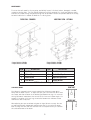
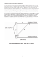
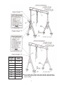
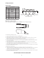
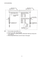
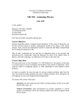
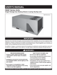
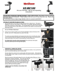
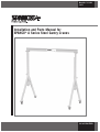
Manual No. 103-0002
08/14
Installation and Parts Manual for
SPANCO ® A Series Steel Gantry Cranes
ISO 9001 REGISTERED
2
TABLE OF CONTENTS
Warnings.................................................................................................................... 3
Assembly and Operation...............................................................................................4
Track Installation Instructions.......................................................................................6
Parts Breakdown Drawing.............................................................................................7
Bill of Materials.......................................................................................................... 8
Optional Accessories....................................................................................................9
Lift Kit Instruction.....................................................................................................10
Warranty and Service Policy........................................................................................12
• Do not lift or support humans.
• When moving gantry, keep load as close to the floor as possible and
position the load in the center of the I-beam.
• Ensure the load is not attached to the floor and remove any obstacles that
impede lifting.
• Adjustments and/or repairs should be made in an area where it will have
the least interference with operation.
• Secure trolley and hoist in the center of I-beam when adjusting height.
• Ensure the rated capacity is clearly labeled on each side of the I-beam.
• Do not adjust the height when gantry is under load.
• Do not lift more than the rated capacity.
• Do not push or pull gantry with a forklift or other vehicle.
• Do not allow the load to swing or roll against support members.
• Push the gantry, not the load.
• Inspect gantry for missing or broken parts before operating.
3
ASSEMBLY INSTRUCTIONS:
1. For assembly, when possible, select an area under an overhead hoist, or where a lift truck can be
used to raise the I-beam. Be sure there is no machinery or clutter nearby that will hamper free
movement. All personnel should be wearing applicable safety gear, such as hard hats, safety shoes,
and safety glasses.
2. Lay both “A” frames flat on the floor, and slide upright tube into top of center tube. Upright tube
should then be pinned into its lowest position, making sure that load pin is fully engaged.
3. The caster wheels should then be locked in position parallel to the “A” frame. This will prevent the
frame assembly from rolling away when lifted to the upright position.
4. Using an overhead hoist or lift truck, lift the I-beam to the gantry's minimum height. Be sure
that the holes in the I-beam flange are on the bottom, and that the capacity rating is right side up
and legible.
5. Lift one end of the frame assembly into position under one end of the I-beam, and bolt I-beam to
top plate of the upright with the hardware supplied. Be sure the lifting lug is on the outside of the
frame assembly, not facing the I-beam. Next, raise into position the other end frame and bolt
together as above.
6. Testing. We certify that the equipment referenced in this manual is in conformance with our
interpretation of applicable CMAA 74, ANSI B30.17, AISC ASD 9th Edition, and AWS D1.1.
This equipment is designed and manufactured to the rated capacity marked on the equipment with
due allowances for safety factors. It is recommended that a person appointed by the owner, under
the direction of a qualified technical person, shall perform a load test of 125% of the rated capacity
before placing the unit into service. See the latest edition of ANSI B30.17 for clarification of
details related to rated load tests.
7. Your SPANCO gantry is now ready to use, and you can now adjust the I-beam to desired height.
8. First secure the trolley and hoist in the center of the I-beam. To raise or lower unit height,
simply hang the optional “LUG-ALL” winch kit (if ordered with the gantry), or any other type of
“come-along”, from the lifting lug at the top of the A-frame. Now pull the bottom hook of the
“LUG-ALL” winch down and hook it under the end of the upright tube. By raising the upright
slightly, you can now pull back the spring-loaded adjustment pin. Secure the adjustment pin in the
lockout position. By operating the “LUG-ALL”, you can raise or lower the height of the gantry.
When desired height is reached, release the load pin. The load pin will self locate the hole in the
upright. Be sure the load pin is in the full lock-in position.
NOTE: This operation requires a “LUG-ALL” winch on each end of the unit. Both ends must be raised or lowered at the
same time. Never adjust gantry while it is supporting a load. Make sure that the “LUG-ALL” or “come-along” used for
height adjustment has a combined capacity rating equal to the weight of the I-beam and any hoist trolley that is
suspended from the I-beam.
4
MAINTENANCE:
To ensure the safe operation of your gantry, periodically inspect it for bent, broken, damaged, corroded,
cracked or missing parts. The only regular maintenance that is required is to check bolt tightness and to
lubricate the casters through the grease fittings that are provided. Casters are prelubricated at the factory,
but when lubrication is needed use NLGI No.1 or No.2 grease.
ADJUSTABLE SPAN - OPTIONAL
FIXED SPAN - STANDARD
* Torque 5/8 bolt to 154 ft/lbs
* Torque 3/4 bolt to 257 ft/lbs
ITEM
* Torque 5/8 bolt to 108 ft/lbs
* Torque 3/4 bolt to 210 ft/lbs
DESCRIPTION
ITEM
DESCRIPTION
1
Hex Bolt
5
Hex Nut
2
I-Beam Clamp
6
Socket Head Cap Screw
3
Bevel Washer
7
Adjustable Span Plate
4
Lock Washer
8
Clipped Washer
NOTE: Item 8 varies with gantry model
RIGHT WAY
SPAN ADJUSTMENT:
The I-Beam is clamped in place at each end with four (4) beam clamps which
firmly hold the beam in place. To adjust the span, just loosen the bolts which hold
the clamps and slide the beam to the desired span between the legs. Do not move
the legs (A-frames) inward more than one half (1/2) of the total I-Beam length. For
example, if the beam is 12 feet long, the distance between the A-Frames should
never be less than six (6) feet.
After adjusting the span as desired, re-tighten all eight (8) bolts securely. Be sure
you adjust both frames inward when adjusting the span so one end of the beam
does not hang over more than the other end. Do not suspend a trolley or load from
the cantilevered ends of the beam.
5
WRONG WAY
V-GROOVE INSTALLATION INSTRUCTIONS FOR GANTRY CRANES:
The exact span of the crane may vary from the design span. We recommend installing the track on one side
making sure that the track is straight and level. Lay one or two sections of the track down at the design span,
assemble crane on the tracks following assembly instructions and operate the crane back and forth a few
times, being careful not to run the crane off the tracks. The loose sections of track will float and set the track
to the crane span. Once the operating span is determined, attach all the other sections of track to the floor
making sure the track is straight, level, parallel, and at the same elevation as the first track. The end stops
should be set square with the 3-4-5 right triangle. The sides and the hypotenuse can be multiplied by any
convenient number such as three used in the example.
Set one end stop at point A, measure along runway track nine feet from point A to point B. With B as a center
and fifteen feet as a radius, draw a circular arc on the floor, with point A as a center and 12 ft. as a radius.
Draw a circular arc on the floor intersecting the other arc at C. A line running through points A and C is
perpendicular, or square, with the runway track. Extend this line to the other runway track to locate the end
stop on that runway. Repeat the process at the other end of the runway, or measure along each runway the
same distance from these end stops for locating the stops at the other end of the runways.
NOTE: SPANCO recommends lagging with 3/8” lag bolts every 3’-0” staggered.
6
FASTENER
SIZE
TORQUE
1/4”
10 ft./lbs.
5/16”
19 ft./lbs.
3/8”
33 ft./lbs.
7/16”
54 ft./lbs.
1/2”
58 ft./lbs.
9/16”
114 ft./lbs.
5/8”
162 ft./lbs.
3/4”
288 ft./lbs.
t This is a general chart of fastener torque values. This table is based upon Grade 5
fasteners. Note that lower grades of bolts may not take these high torques. Reduce
values accordingly.
7
BILL OF MATERIALS
1
I-Beam
1
2
Upright Tube
2
3
End Frame/A Frame
2
16
Caster
4
18
Lock Washer
16
18A
Flat Washer
16
19
Hex Bolt
16
20
Hex Bolt
16
28
Hex Bolt
8
29
Lock Washer
8
30
Hex Nut
8
31
Bevel Washer
8
32
Optional LUG-ALL® Winch Kit
2
33
Safety Instruction
2
34
Safety Instruction
2
35
Capacity Decal
2
36
Capacity Decal
2
OPTIONAL SPAN ADJUSTMENT KIT (see page 5)
37
Span Adjustment Plates
2
38
Flat Head Socket Head Cap Screw
8
39
Hex Nut
8
40
Lock Washer
8
41
I-Beam Clamp
8
NOTE: ITEM No. 1 IS CAPPED WHEN REQUIRED
ITEM No. 35 IS FOR 8” THRU 12” I-BEAMS.
ITEM No. 36 IS FOR 15” THRU 24” I-BEAMS.
If replacement parts are required, please supply the complete gantry model, and serial number from
the label affixed to the A-frame, as well as the item number of the part(s) on the drawing and bill of
materials.
Safety instruction labels should be in readable condition at all times. If any become lost or
damaged, please notify SPANCO with the gantry serial number immediately, and they will be
replaced at no charge.
8
OPTIONAL ACCESSORIES:
Tagline Assembly
BILL OF MATERIALS
ITEM
DESCRIPTION
QTY
7
Cable Ties
5
6
Hex Nuts
4
5
Pulleys
5
4
Eye Bolts
2
3
Cable Clamps
2
2
Tagline Cable
1
1
Trolley Stops
2
4
6
3
5' - 0"
5' - 0"
2
7
1
5
TO EQUIPMENT
FROM SUPPLY
(CONDUCTOR NOT SUPPLIED)
Wheel Brake Assembly Installation
For 6” and some 8” diameter casters on SPANCO “A” & “E” Series Gantries
To set brake while assembling the caster:
1. Inspect the brake mechanism to ensure it is in working order.
2. Make sure the brake pedal is in the “off” position (pedal is in the up position).
3. Create additional clearance for the brake pad. To do this, loosen the jam nut on the brake pad with a 1/2” wrench.
Rotate the brake pad clockwise so it moves toward the shoe/nut assembly.
4. Position the brake brackets over the outside of the fork legs. Line the bolt holes over each fork's bolt holes.
5. Insert the wheel between the fork legs and place the axle through the brake/fork holes and the wheel hub. Thread the
nut on the axle and tighten.
6. Move the brake pedal to the “on” position (pedal is in the downward position). Rotate the brake pad outward
(counterclockwise) to where it comes into contact with the wheel tread.
7. Set the brake pedal to the “off” position and rotate the brake pad counterclockwise until you’ve reached the desired
brake strength; testing by applying the brake and rotating the wheel with your hand.
8. Once the desired brake strength is reached, hold the brake pad in place with your hand and tighten the jam nut against
the shoe/nut assembly with a 1/2” wrench.
To adjust brake on mounted caster:
1. Inspect brake mechanism for damage that cause binding to the brake pad or the mounting bracket.
2. To adjust the brake pad, set the brake pedal to the off position (pedal is in the up position). Loosen the jam nut with a
1/2” wrench. Turn the brake pad clockwise (toward the shoe/nut assembly) to decrease the brake strength, or
counterclockwise to increase the brake strength.
3. Once the desired brake strength is reached, hold the brake pad in place with your hand and tighten the jam nut against
the shoe/nut assembly with a 1/2” wrench.
NOTE: NEVER CHANGE CASTERS WITH A LOAD ON GANTRY!
9
LIFT KIT INSTRUCTIONS:
NOTE: 1. To be used under no load conditions only.
2. For use on “A” or “ALU” series gantries only.
3. For kits supplied with an adapter lug, DO NOT use without winch adapter lug or damage to the
crane could result.
4. Before removing LUG-ALL® winch, ensure that load pin is fully engaged.
10
11
SPANCO, Inc.
604 Hemlock Road
Morgantown, PA, 19543
Toll Free: (800) 869-2080
Local: (610) 286-7200
Fax: (610) 286-0085
Spanco.com
TEN-YEAR SPANCO WARRANTY
Products covered under the Ten-Year Warranty:
•
•
•
•
Manual
Manual
Manual
Manual
Steel Freestanding, Ceiling Mounted Workstation Bridge Cranes, and Monorails
Aluminum (Alu-Track®) Workstation Bridge Cranes and Monorails
Jib Cranes (I-Beam, Articulating, and Workstation Jib Cranes)
Gantry Cranes and Tripods
What the Ten-Year Warranty covers:
• Defects in Equipment material and workmanship
• Wearable parts (end truck and hoist trolley wheels only)
Spanco, Inc. warrants its manual workstation bridge crane products, jib crane products, and gantry crane products
to be free from defects in material and workmanship for a period of ten (10) years or 20,000 hours, commencing
on the date of shipment to the first retail purchaser. This warranty extends to non-wearable parts only, with the
exception of the wheels supplied on manually operated workstation end trucks and hoist trolleys. This warranty
does not cover defective equipment or system failure caused by misuse, negligence, improper installation or
maintenance, or equipment that has been used in excess of its rated capacity or beyond its service factors. It
does not apply to equipment that has been altered without Spanco’s written authorization.
Written notice of any claimed system defect must be given to Spanco within thirty days of discovery. Spanco's
obligation under this warranty is limited to the replacement or repair of Spanco’s products at the factory or
separate location approved by Spanco. The purchaser is responsible for all freight and transportation costs relating
to equipment repair or replacement. Other than the abovementioned warranty, Spanco will not honor any other
warranties—whether express, implied, or statutory—and disclaims any warranties of merchantability or fitness for a
particular purpose. Spanco is not liable—under any circumstances—for any indirect, incidental, or consequential
damages including but not limited to lost profits, increased operating costs, or loss of production.
This warranty does not extend to components or accessories not manufactured by Spanco. The purchaser’s remedy
for such components and accessories will be determined by the terms and conditions of any the warranty provided
by the manufacturer of such components and accessories.
NOTE: All motorized Spanco products come with a One-Year Warranty on drive components.
12