1
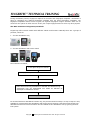
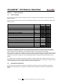
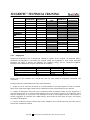
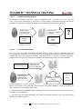
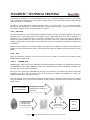
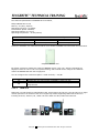
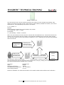
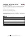
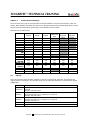
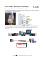
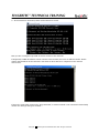
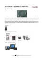
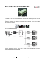
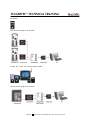
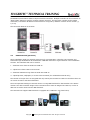
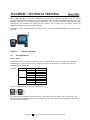
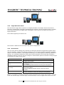
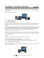
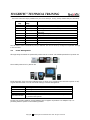
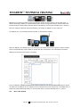
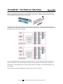
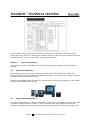
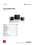
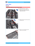
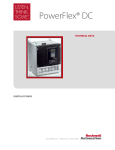
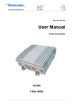
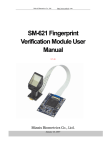
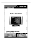
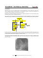
FINGERTEC® TECHNICAL TRAINING
Introduction
Biometrics refers to two very different fields of study and application. The first, which is the older and is
used in biological studies, including forestry, is the collection, synthesis, analysis and management of
quantitative data on biological communities such as forests.
Biometrics in reference to biological sciences has been studied and applied for several generations and is
somewhat simply viewed as "biological statistics."
More recently and incongruently, the term's meaning has been broadened to include the study of
methods for uniquely recognizing humans based upon one or more intrinsic physical or behavioral traits.
FingerTec® system is using fingerprint as main enrollment and verification method. Fingerprint is the
most convenience physiological identities among all. During fingerprint capturing, FingerTec® terminal
is capturing the minutia points of fingerprint, instead of image.
The three basic patterns of fingerprint ridges are the arch, loop, and whorl. An arch is a pattern where
the ridges enter from one side of the finger, rise in the center forming an arc, and then exit the other
side of the finger.
Copyright
2008 FingerTec Worldwide Sdn. Bhd. All rights reserved.
FINGERTEC® TECHNICAL TRAINING
The loop is a pattern where the ridges enter from one side of a finger, form a curve, and tend to exit
from the same side they enter.
In the whorl pattern, ridges form circularly around a central point on the finger. Scientists have found
that family members often share the same general fingerprint patterns, leading to the belief that these
patterns are inherited.
The major Minutia features of fingerprint ridges are: ridge ending, bifurcation, and short ridge (or dot).
The ridge ending is the point at which a ridge terminates.
Copyright
2008 FingerTec Worldwide Sdn. Bhd. All rights reserved.
FINGERTEC® TECHNICAL TRAINING
Bifurcations are points at which a single ridge splits into two ridges.
Short ridges (or dots) are ridges which are significantly shorter than the average ridge length on the
fingerprint.
Minutiae and patterns are very important in the analysis of fingerprints since no two fingers have been
shown to be identical.
The fingerprint capturing mechanism is as below,
Captured and converted into
minutiae points
Original fingerprint
Copyright
Fingerprint templates
2008 FingerTec Worldwide Sdn. Bhd. All rights reserved.
FINGERTEC® TECHNICAL TRAINING
During verification process, fingerprint captured is converted into fingerprint templates. Verification is
done by comparing the captured fingerprint template with the stored fingerprint templates. The
fingerprint templates cannot reverse to gain the orgininal fingerprint images. Therefore there are no
worries for the system or other users to “steal” your unique fingerprint and use it for any other purpose.
The Main Functions of FingerTec® Terminals
FingerTec® offers several models with different outlook and functions. Basically there are 2 groups of
products, which are
1 – for time attendance only
2 – for time attendance and access control
The workflow is as below,
1. User place finger on scanner.
2. Fingerprint captured and converted into templates.
3. System verifies users’ identities.
4. Date and time during verification is recorded as Transaction Log.
Transaction logs are downloaded into TCMS V2 software as
displayed as attendance records.
5. Door opened for users
For terminal with time attendance function only, the process starts from step 1 to step 4. Step 5 is only
available for terminal with time attendance and access control functions. Therefore terminal with time
attendance and access control functions can be installed as time attendance unit by ignoring the door
lock system.
Copyright
2008 FingerTec Worldwide Sdn. Bhd. All rights reserved.
FINGERTEC® TECHNICAL TRAINING
Chapter 1
1.1
Basic operations
Users’ Privilege
For all models (except i-Kiosk 100 series), there are 3 levels of users’ privileges, which are supervisor,
admin and users.
There are differences for users’ privilege. The highest authorities is Supervisor, followed by Admin, and
lowest is users.
Functions available
Clear all data
Clear attendance data
Delete user
Reset to default settings
Configure matching threshold
Enable/Disable voice greeting
Enable/Disable card verification
Enable/Disable Antipassback
Enable/Disable WorkCodes
Change Date/Time
Change Languages
Change communication settings
Change power on/off settings
Check device storage and information
Enroll new users
Enroll new Admin
Enroll new supervisor
Verify to report attendance or gain access
Supervisor
Yes
Yes
Yes
Yes
Yes
Yes
Yes
Yes
Yes
Yes
Yes
Yes
Yes
Yes
Yes
Yes
Yes
Yes
Admin
User
Yes
Yes
Yes
Yes
Yes
Yes
Yes
Yes
Yes
Therefore it is advisable to assign a trust worthy person as Supervisor to take control of the system.
Please always request Supervisor to clear admin privilege if he/she is no longer to take control of the
system. Please refer the hardware user manual and VCD for more details for each model.
The enrollment of supervisor or admin can be done at the terminal during first enrollment. Anyway there
is alternative to change users privilege by using FingerTec® TCMS V2 software. This alternative is easier
compare to enrollment. Please refer to the FingerTec® TCMS V2 software manual and VCD for more
details.
For i-Kiosk100 series models, the privilege of Admin is same as Supervisor. Therefore there are only 2
levels of privilege in i-Kiosk 100 series models, which are Admin and Users. Therefore in i-Kiosk 100 and
i-Kiosk 100Plus, Admin is the highest authorities, similar to Supervisor.
1.2
Enrollment & Verification
There are 4 types of enrollment methods in FingerTec® terminals, which are fingerprint, password,
MIFARE card, and RFID card. The types of enrollment and verification methods for all models are as
below,
Copyright
2008 FingerTec Worldwide Sdn. Bhd. All rights reserved.
FINGERTEC® TECHNICAL TRAINING
AC100
AC103-R
TA100
TA103-R
AC100Plus
AC800
AC800Plus
AC800Plus
MC
AC900
M2
R2
R2 MIFARE
iKiosk 100
i-Kiosk
100Plus
TimeLine
Kadex
1.2.1
Fingerprint
Password
Yes
Yes
Yes
Yes
Yes
Yes
Yes
Yes
Yes
Yes
Yes
Yes
Yes
Yes
Yes
Yes
Yes
Yes
Yes
Yes
Yes
Yes
Yes
Yes
Yes
Yes
Yes
MIFARE
card
RFID card
Different
verification
Yes
Yes
Yes
Yes
Yes
Yes
Yes
Yes
Yes
Yes
Yes
Yes
Yes
Yes
Yes
Yes
Yes
Yes
Fingerprint
Fingerprint enrollment is the most general method to register at the terminal. As discussed before,
enrollment of fingerprint is converting the original image into templates to store inside terminals.
Therefore the types of scanner are affecting the capturing image, and its converted templates.
Furthermore the differences of types of scanners are as below,
Response time interval
Quality of image capture
Power consumption
Cost
Optical scanner
Medium
Normal
High
Low
URU scanner
Medium
Good
Normal
Normal
UPEK scanner
Fast
Best
Low
High
Please refer to the hardware user manual and VCD for more details in fingerprint enrollment and
verification.
During enrollment, please kindly take note of the followings,
1 – Finger to use to enroll into terminals. It is recommended to use index fingers to enroll to terminal.
Some users might have bigger thumb and it is difficult for them to place fingers on the scanner.
2 – Quality of fingerprint. Check the user’s fingerprint before enrollment. Make sure the fingerprint is
clear and without any cut or wound. Please advice users to use another fingers to do enrollment. Users
with blur fingerprints, or cut wound is not advisable to enroll by using optical scanner. URU scanner is
another suggestion to overcome this. UPEK scanner, which scans the inner layer of finger, can capture
any kinds of fingerprints.
3 – Proper enrollment method. Please refer to the hardware user manual and user self learn VCD to
learn proper enrollment method.
Copyright
2008 FingerTec Worldwide Sdn. Bhd. All rights reserved.
FINGERTEC® TECHNICAL TRAINING
1.2.1.1
1 to many matching method
For fingerprint verification, there are 2 types of operations, either “1 to many” or “1 to 1”. In “1 to
many”, user will only place finger on the scanner. Terminal captures fingerprint image and convert into
templates. The system will search and compare the templates with those stored in memory.
Captured and
converted into
minutiae points
1.2.1.2
Searching into
memory for matched
templates
Please try
again
User ID 000012
Henry
Verified
If failed to verified
If successes
?
1 to 1 matching method
For “1 to 1”, user must enter user ID and then place finger on scanner. Terminal automatic search the
stored fingerprint templates for the entered user ID. The fingerprint template is ready and awaiting to
compare with the input fingerprint template. User places finger on scanner to capture fingerprint.
Fingerprint then converted into fingerprint templates and compare with ready fingerprint templates.
User enter user ID
Searching into
memory for the
user ID’s template
User ID
000012
Captured and
converted into
minutiae points
Verification process
running
Henry
Verified
In term of speed, “1 to many” matching method is faster than “1 to 1”. In this method, user does not
enter any user ID but only place finger on the scanner. The system captures, search and verified the
users. Anyway the system takes longer time if
1 – the total fingerprint templates stored exceeding 50% of the total. System needs to spend more time
to search in a larger database.
2 – the users with poor quality fingerprint. The captured fingerprint template is not clear and therefore
affecting the searching speed.
Copyright
2008 FingerTec Worldwide Sdn. Bhd. All rights reserved.
FINGERTEC® TECHNICAL TRAINING
Under these 2 conditions, it is recommended to use “1 to 1” matching method. The system can directly
look for fingerprint templates for a user after receiving user ID. The verification process is started when
user place finger on the scanner.
By default, every FingerTec® terminal supports both “1 to many” and “1 to 1” matching method.
Anyway you can disable the 1 to many methods by configuring the setting in terminal. The terminal will
not capture fingerprint when user place finger on scanner.
1.2.2
Password
It is recommended for uses to enroll with password if cannot enroll with fingerprint (disable, poor quality
fingerprint etc). FingerTec® terminal can support up to 5-digits password. Each user is entitling to 1
password only, and password can be changed. Password user must enter user ID and follow by
password to verify identity. For both i-Kiosk 100 and i-Kiosk 100 Plus, the maximum password length is
8-digits. Please refer to the hardware user manual and VCD for more details in password enrollment and
verification.
Beside to enroll password in terminal, password can register at the TCMS V2. Password can upload from
TCMS V2 to the terminal. Please refer to the FingerTec® TCMS V2 software manual and VCD for more
details.
1.2.3
Card
Some of FingerTec® terminals can read and verify users via cards. The terminals can support either
MIFARE cards or RFID cards.
1.2.3.1
MIFARE card
MIFARE card is card to store user information including fingerprint templates. For FingerTec® terminals
model AC800Plus MC and R2 MIFARE, terminal can read and write the user’s fingerprint templates into
the card, but not the others information.
Every time user will bring the MIFARE card and wave it to terminal, so terminal will read the fingerprint
templates from card. The user places finger on the scanner to capture his fingerprint to verify with
fingerprint templates captured from card.
Users can choose not to store his/her fingerprint templates in the terminals. Therefore user must always
carry the MIFARE card to verify at the terminals. In this scenario, the terminal can supports up to 4000
cards (users).
User waves MIFARE
card to terminal
Fingerprint templates
captured into memory of
terminal
Captured and
converted into
minutiae points
User ID
000012
Verification
process running
Henry
Verified
Copyright
2008 FingerTec Worldwide Sdn. Bhd. All rights reserved.
FINGERTEC® TECHNICAL TRAINING
The technical specifications of MIFARE card is as below,
Philips MIFARE S50 or S70
Memory: 1K (S50), 4K(S70)
Operating Frequency: 13.56MHz
Transmission Speed: 106kbit/s
Operating Distance: 2.5-10cm
Operating Temperature: -20-85 (Celsius)
Differences of MIFARE card with S50 and S70 chipset
S50
S70
Memory size
1k
4k
Fingerprint storage
4 templates
10 templates
Please see hardware user manual and VCD for more details in MIFARE card enrollment and verification.
Sample of MIFARE card
By default, terminal is reading the content of MIFARE card to verify user, without requesting the
fingerprint from the users. This is an optional setting, and terminal can be configure to read both
content of MIFARE card and user’s fingerprint.
You can configure this in Advance Option > Read Card only > Yes/No
Read card only
Yes
No
1.2.3.2
Operation of terminal
Terminal will only read content of MIFARE to verify the user.
Terminal will read content of MIFARE card and user’s fingerprint to
verify the user
RFID card
RFID card is a radio frequency identification card, which storing card ID only. The card ID is a 10-digits
number printed on the surface of the card. FingerTec® models supporting RFID card function are
including AC103-R, TA103-R, R2, i-Kiosk 100 and i-Kiosk 100 Plus, Kadex and TimeLine.
Copyright
2008 FingerTec Worldwide Sdn. Bhd. All rights reserved.
FINGERTEC® TECHNICAL TRAINING
Sample of RFID card.
You will see there are 3 sets of numbers printed on the surface of card, example 0001747879, 026,
43943. FingerTec® terminals will only read number A (0001747879) as RFID card number, but not the
number B or C. The relationship of A, B and C is as below,
A = B * 65536 + C
Example
Number printed on RFID Card = 0001747879, 026, 43943
A = 1747879, B = 26, C = 43943
As calculate,
A = (26 x 65536) + 43943 = 1747879
When user wave RFID card to the terminal, terminal will read Card ID from it. Terminal will search into
memory for user ID pairs with the Card ID. The fingerprint templates for the user ID is from memory
and user place finger to verify. This scenario is similar to “1 to 1” matching, but user does not physically
enter the user ID.
User wave RFID
ID card to the
terminal
Searching into
memory for the
user ID’s template
User ID
000012
Captured and
converted into
minutiae points
Verification process running
Henry
Verified
The terminal is storing users’ fingerprint templates and Card ID. Therefore user must verify by RFID
card and fingerprints. Anyway terminal can be configured to verify by reading users’ RFID card only.
The technical specifications of RFID card is as below,
Card Type:
Code:
Resonance Frequency:
Card Operating Temperature:
Card reading distance:
EM RFID card
64 bits
125kHz
-10 ~ 50 Celsius
0~5 cm
Please see hardware user manual and VCD for more details in RFID card enrollment and verification.
Copyright
2008 FingerTec Worldwide Sdn. Bhd. All rights reserved.
FINGERTEC® TECHNICAL TRAINING
1.2.4
Different Verification Method
As described before, few models of FingerTec® terminals can support different verification. In these
terminals, users divided into 5 groups and each group of users verifies by combinations of 2 to 3
verification methods.
Example
Users in Group 1 – verify by using fingerprint only
Users in Group 2 – verify by using fingerprint + password
Users in Group 3 – verify by using password + RFID card
There are total of 15 types of combinations available to choose to assign to each group. You can use
FingerTec® TCMS V2 software to configure to assign users into group, and to assign the combination of
verification methods to the groups.
The details of verification methods are as below,
Type of
verifications
FP / PW / RF
FP
PIN
PW
RF
FP / PW
FP / RF
PW / RF
PIN & FP
FP & PW
FP & RF
PW & RF
FP & PW & RF
PIN & FP & PW
FP & RF / PIN
Operations
Reader verifies
Reader verifies
Reader verifies
Reader verifies
Reader verifies
Reader verifies
Reader verifies
Reader verifies
Reader verifies
Reader verifies
Reader verifies
Reader verifies
Reader verifies
Reader verifies
Reader verifies
matching.
Copyright
users
users
users
users
users
users
users
users
users
users
users
users
users
users
users
via fingerprint, password or RFID card.
via fingerprint only.
via User ID only.
via password only.
via RFID card only.
either via fingerprint or password.
either via fingerprint or RFID card.
either via password or RFID card.
via 1:1 fingerprint matching only.
via fingerprint with password only.
via fingerprint with RFID card only.
via password with RFID card only.
via fingerprint + password + RFID card.
via User ID + fingerprint + password.
either via fingerprint + RFID card or 1:1 fingerprint
2008 FingerTec Worldwide Sdn. Bhd. All rights reserved.
FINGERTEC® TECHNICAL TRAINING
Chapter 2
Communication Settings
There are total of 6 types of communication methods available in FingerTec® terminals, which are
TCP/IP, RS23, RS485, USB flash disk (pen drive), Wiegand 26-bits input and Wiegand 26-bits output.
Anyway some communication option might not available in some models.
Please check the table below.
AC100
AC103-R
TA100
TA103-R
AC100Plus
AC800
AC800Plus
AC800Plus
MC
AC900
M2
R2
R2
MIFARE
iKiosk 100
iKiosk
100Plus
TimeLine
Kadex
Kadex U
2.1
26-bits
Wiegand
Input
26-bits
Wiegand
Output
TCP/IP
RS232
RS485
USB flash
disk
Yes
Yes
Yes
Yes
Yes
Yes
Yes
Yes
Yes
Yes
Yes
Yes
Yes
Yes
Yes
Yes
Yes
Yes
Yes
Yes
Yes
Yes
Yes
Yes
Yes
Yes
Yes
Yes
Yes
Yes
Yes
Yes
Yes
Yes
Yes
Yes
Yes
Yes
Yes
Yes
Yes
Yes
Yes
Yes
Yes
Yes
Yes
Yes
Yes
Yes
Yes
Yes
Yes
Yes
Yes
Yes
Yes
Yes
Yes
Yes
Yes
Yes
Yes
Yes
Yes
Yes
Yes
Yes
Yes
Yes
Yes
Yes
Yes
Yes
Yes
Yes
Yes
Yes
Yes
Yes
TCP/IP
The most common communication method to connect to FingerTec® terminals. All terminals can
support TCP/IP connections. In terminals, these are the important settings in communication option
(COMM Opt),
IP address
NetMask
GateWay
Netspeed
Dev num
Functions
To assign an IP address to the terminal, so software can connect to the
terminal.
Example 192.168.1.201
NetMask settings to suit into the network envionment. Ignore if you are
connecting direct from 1 computer to 1 terminal.
Example 255.255.255.0
Gateway settings to suit into network environment. Ignore if you are
connecting direct from 1 computer to 1 terminal.
Example 192.168.1.1
Network speed of the network environment, recommeneded AUTO.
The number of device, range from 1 to 255.
Copyright
2008 FingerTec Worldwide Sdn. Bhd. All rights reserved.
FINGERTEC® TECHNICAL TRAINING
2.1.1
Configurations of network cables and their connections
There are 2 types of configurations of network cable, which are straight-T and cross-link. The difference
is the arrangement of whips inside the cable.
There are 8 whips inside a network cable and each with different color to indicate their position. If the
RJ45 jacks for both ends are with same whips positioning, this is a straight-T network cable. Straight-T
network cable suitable to use to connect into network switches, and it is widely used in a network
environment.
Straight-T
Network
cables
Copyright
2008 FingerTec Worldwide Sdn. Bhd. All rights reserved.
FINGERTEC® TECHNICAL TRAINING
If the RJ 45 jack for both ends are different in whips arrangement, then it is called cross-link network
cable. Please see its configuration for both RJ45 jacks as below,
RJ45 Jack A
RJ45 Jack B
Orange stripe
Green stripe
Orange
Green stripe
Blue
Green
Orange stripe
Blue
Blue stripe
Blue stripe
Green
Brown stripe
Orange
Brown
Brown
Brown stripe
Cross-link network cable is used when 1 terminal is connecting directly into a computer.
Cross-link
Network
cables
2.1.2
To check the connection from computer to the terminal
The simplest method to check the connectivity of terminal and computer is to use “ping command”. The
steps are
1 – Press “Windows Start” button
2 – Select “Run”.
3 – Enter “cmd” and press enter.
4 – In DOS command page, enter “ping IP address of the terminal”, example “ping 192.168.1.168” and
press enter.
Copyright
2008 FingerTec Worldwide Sdn. Bhd. All rights reserved.
FINGERTEC® TECHNICAL TRAINING
5 – If the terminal is connected, these will be showed on screen.
Now you can run FingerTec® TCMS V2 and to connect to this terminal.
If FingerTec® TCMS V2 software cannot connect to the terminal, there are IP address conflict. Please
confirm the IP address of the terminal is not same as other devices or computers in the network
environment.
If this is the result after entering the “ping command”, it means terminal is not connected. Please kindly
recheck the settings and types of cables.
Copyright
2008 FingerTec Worldwide Sdn. Bhd. All rights reserved.
FINGERTEC® TECHNICAL TRAINING
2.2
RS232 cable
RS232 cable is the easiest way for reader to communicate with computer. By lugging in the RS232 cable
to computer, reader could communicate with computer. No other special device is required. It is also the
most cost saving method. The RS232 cable used for installation could not exceed 3 meters.
For few FingerTec® models, you cannot plug the RS232 cable directly because the terminals do not
equipped with the 9-pins serial port. These models are AC800Plus, AC800PlusMC, AC900, M2, R2, iKiosk 100 and i-Kiosk 100Plus. You will need to prepare the connecting cable, and make use of RX, TX
and GND at the back of terminal.
For AC900
The connection diagram is as below,
For M2, R2, i-Kiosk 100, Kadex
Copyright
2008 FingerTec Worldwide Sdn. Bhd. All rights reserved.
FINGERTEC® TECHNICAL TRAINING
The connection diagram is as below,
For other models, AC100 series, TA100 series and TimeLine, they are equipped with 9-pins serial port.
You can plug the RS232 cable directly.
You will need to configure the settings in communication option (COMM Opt) as below,
Dev num
Baud rate
RS2332
RS485
Functions
The number of device, range from 1 to 255.
To configure the data transfer speed, recommended 115200
To enable/disable RS232 connection, turn to Y
To enable/disable RS485 connection, turn to N.
If connection between reader and computer is failed, it is difficult to identify the factor. Even if this is
the easiest way of connection, but it is not convenient to identify problems when connection failed.
Furthermore RS232 cable does not allow multiple terminals connecting to 1 computer. RS232 cable
allows 1 terminal connects to 1 computer only.
2.3
RS485
RS485 allows multiple terminals (up to 32) to communicate at half-duplex on a single pair of wires, plus
a ground wire, at a distance up to 1000 meters. Both the length of the network and the number of
nodes can easily be extended using a variety of repeater products available in the market. Although
RS485 could use up to 1000m, but 750m is recommended. An RS232/485 Data Converter is required
when choosing RS485 as a communication method.
Sample of RS 232/485 Data converter
The communication wire for RS485 is different from the others, which are 2 wires, RS485A (Data +) and
RS485B (Data -). These wires are looks similar as normal telephone wire, and so it must need a jack (or
plug) to connect to the terminal.
Copyright
2008 FingerTec Worldwide Sdn. Bhd. All rights reserved.
FINGERTEC® TECHNICAL TRAINING
Sample of RS232/485 jack
If the length is more than 1000m, another device, which is a Data Repeater, is required. Each Data
Repeater is effective for each 250 meters. If longer communication wire is required, then extra data
repeater is a must.
For terminals with 9-pins serial port, AC100 series, TA100 series and TimeLine, you can plug the RS485
jack into the terminal directly.
The connection diagram is as below,
Terminals without 9-pins serial port, you will need to prepare the connecting cable, and make use of
RS485A and RS485B at the back of terminal.
Copyright
2008 FingerTec Worldwide Sdn. Bhd. All rights reserved.
FINGERTEC® TECHNICAL TRAINING
For AC900
The connection diagram is as below,
For M2, R2, i-Kiosk 100, i-Kiosk 100Plus, Kadex
The connection diagram is as below,
Copyright
2008 FingerTec Worldwide Sdn. Bhd. All rights reserved.
FINGERTEC® TECHNICAL TRAINING
The RS485 communication allows multiple terminals connection. Multiple terminals can be connected via
“Daisy Chain” pattern to perform a unique network structure. This structure is similar to the TCP/IP
connection, but without IP address. Each terminal is recognize by software via their device number (1,
2, 3 etc)
The connection diagram is as below,
2.4
USB Flash Disk (pen drive)
Some installation might not required extra wiring for communication. Therefore users transfer and
transaction logs download will be troublesome. USB flash disk will be a good solution in this installation
scenario. The USB flash disk can be used for
1 – download users from terminal into TCMS V2
2 – upload users from TCMS V2 to terminal
3 – download transaction logs from terminal into TCMS V2
4 – upload pictures, wallpapers, or music to the terminals (for multimedia terminals only)
The content of the pen drive is encrypted and only read by the terminal or TCMS V2. Therefore there are
no worries to read or edit this information.
The most important settings in terminal when it is using USB flash disk for data transfer is the Device
number. The device number assign to the terminal must be same as assigned in TCMS V2, or else no
data can be read or write into the USB flash disk.
The terminals can support USB flash disk is equipped with a USB port, see photo below,
Copyright
2008 FingerTec Worldwide Sdn. Bhd. All rights reserved.
FINGERTEC® TECHNICAL TRAINING
When USB flash disk is used for transaction logs download, TCMS V2 will not erase the history
transaction logs stored in the terminal. The transaction logs are kept and memory getting less in the
terminal. Therefore it is advisable to delete transaction logs right after download into USB flask disk.
This practice can maintain the memory of the terminal, and to make sure you always getting the
updated transaction logs during each download.
For models i-Kiosk 100 and i-Kiosk 100 Plus, you can choose to upload wallpapers and pictures to the
terminal.
Chapter 3
Functions Available
3.1
Time Attendance
3.1.1
Siren
In some factoires or working environment, siren is installed to alert users to report their attendance,
example start to work, time for lunch, resume from lunch, OT started etc. The delay time of each
schedule can be configured.
Example
Day
Monday
Tuesday
Schedules
08:00
12:00
13:00
18:00
08:00
11:30
12:30
17:00
Delay timer
10s
10s
10s
10s
10s
10s
10s
10s
Siren, or scheduled bell, is a function available in
Terminal is preset with timer (8 timer per day, total of 56 timers) to trigger siren to alert users. The
terminal must connected to a DC5V siren (example air-hon) via a timer delay (integrated in terminal).
The connection is as below.
Copyright
2008 FingerTec Worldwide Sdn. Bhd. All rights reserved.
FINGERTEC® TECHNICAL TRAINING
For i-Kiosk 100 and i-Kiosk 100Plus, there is integrated siren. The terminal does not required any
additonal siren to alert users, but it will alert users by itself. There are few alert sound ready to use.
There are total 60 timers ready to use in i-Kiosk 100 and i-Kiosk 100Plus.
3.1.2
Work Codes
Work code is a special time reporting feature. User needs to provide a reason during his/her identity
verification, example user is late-in due to terrible traffic jam, user came to work late because he
attempt to client during morning time etc. These codes are download together with transaction logs into
TCMS V2. With these extra information, administrator can judge users attendance records without to
question he/she.
In FingerTec® terminal, work codes are preset in TCMS V2, and users will only enter the work codes
before/after a verification process. If users do not enter a preset work code, code 00 (check in) will be
the default value for system to capture. These terminals will only display the work codes in number, but
not in words. The meaning of each work codes will only display in TCMS V2.
Example
Work codes
20
21
22
23
Reasons
Traffic jam
Car breakdown
Delay of public transport
Meeting client
Different from the above models, both i-Kiosk 100 and i-Kiosk 100 Plus can display the names and work
codes on screen. User can check each work codes before he/she enters the work codes. The work codes
are predefined in TCMS V2 and upload to the terminal.
Copyright
2008 FingerTec Worldwide Sdn. Bhd. All rights reserved.
FINGERTEC® TECHNICAL TRAINING
3.2
Door access
3.2.1
Door sensor
FingerTec® terminals can work with door sensor (magnetic switch) to alert user to close the door after
each open. Door sensor is not included in the package. FingerTec® terminal supports 2 types of door
sensor, which are NO (normally open) and NC (normally close).
Please make sure the DOOR SENSOR mode is either NC or NO when you would like to use the option.
Choose DOOR SENSOR as NONE if you do not want to use it.
Door Sensor Mode
NO
NC
NONE
Sensor Delay
Alarm delay
Functions
Door sensor type “normally open” is in use.
Door sensor type “normally close” is in use.
Disbale door sensor function.
To configure time period for internal buzzer to alert user.
To configure time period for terminal to trigger alarm systems.
FingerTec® models support door sensor function are,
The FingerTec® terminals will alert users by the internal buzzer for a preset time period. Terminal will
trigger alarm system if users ignore the alert sound.
3.2.2
Antipassback
Some installation sites might install 2 FingerTec® terminals to control a door. Users must verify their
identities either they are coming in or going out. If one of transaction logs (coming in or going out) is
missing (records not in pairs) the terminal will verify users but door will not open to the user. This is
called antipassback, where system will always check users previous transaction logs before allowing user
to login or logout in the next trial.
The 2 terminals are communicating via Wiegand 26-bits input and output. The difference settings
between the master and slave are
Models support
Wiegand Communication
Device number
Antipassback
Door lock system controlling
Copyright
Master
M2, R2, i-Kiosk 100, Kadex
26-bits input
1
IN
Yes
Slave
M2, R2, i-Kiosk 100, Kadex
26-bits output
2
OUT
No
2008 FingerTec Worldwide Sdn. Bhd. All rights reserved.
FINGERTEC® TECHNICAL TRAINING
3.2.3
Illegal Dismantle Alarm
The terminal will trigger alarm system if it is illegally dismantle. The tamper switch at the back of
terminal is released when somebody is dismantling the terminal. The word “System broken” is display
on the LCD and terminal will trigger alarm immediately. This function is to protect the terminal is
illegally dismantle.
The models supporting this function are
This function is default and do not require any special configurations.
3.2.4
Duress Alarm
User can verify his/her identity at the terminal to control the terminal to trigger alarm system during
case of emergency, example tail-gating by strangers. There are total 4 types of verification methods
ready to use as duress alarm, 1 to1 fingerprint matching, 1 to many fingerprint matching, password or
help key. The verification method for duress alarm must be different from normal daily verification
methods to avoid any miss use. You can configure in Duress Alarm option in terminal to configure types
of verification to trigger duress alarm,
Types of duress alarm
Help Key
1 to 1
1 to many
Password.
Functions
Hold ▲for 3 sec and verify identity (any verification methods)
to trigger duress alarm.
User verifies fingerprint via 1 to 1 matching method to trigger
duress alarm.
1 to 1 matching method cannot use during normal operation.
User verifies fingerprint via 1 to many matching method to
trigger duress alarm.
1 to many matching method cannot use during normal
operation.
User enters password to verify to trigger duress alarm.
Password verification cannot use during normal operation.
Beside to use different verification methods for daily operations and to trigger duress alarm, users can
enroll with another finger as duress finger. The duress finger is use to trigger duress alarm only. The
Copyright
2008 FingerTec Worldwide Sdn. Bhd. All rights reserved.
FINGERTEC® TECHNICAL TRAINING
duress finger enrollment process is same as normal enrollment, but will only done in Duress Alarm
option. If users enroll with more than 1 finger, user can choose to define one of his enrolled fingerprints
as duress finger.
Models support duress alarms are,
3.3
Multimedia features
3.3.1
Short messages display
There are 2 types of short messages available in FingerTec® terminals, which are Public Messages and
Personal Messages. You can configure the valid time period for each message without to clear them
manually.
Public messages are display on the screen of terminal all the time (for model M2, R2, and Kadex). Users
can read it anytime by looking at the screen of terminal. Anyway for model i-Kiosk 100 and i-Kiosk 100
Plus, users need to press the hatch button (#) then terminal will display the public messages. Example,
“Company trip to Europe is now open for registration. Please contact HR for more details.”
Valid time period: 1st July to 31st July 2008.
Personal messages are only display to users after verification process. You can choose to allow certain
users to view the message. You can configure the valid time period for each personal message without
to clear them manually.
Example,
“To all managers, operation meeting in Room Alpha at 10am, 16/7/2008.”
Valid time period: 8:30am to 10:30am, 16/7/2008.
User to view this message: 001001, 002001, 003001, 003501, and 004801.
You can configure the content of the messages in TCMS V2 software and upload to the terminals.
3.3.2
Functional keys (short cut keys)
The color screen model, i-Kiosk 100 and i-Kiosk 100 Plus offers functional keys for faster access into the
system to do configuration.
Copyright
2008 FingerTec Worldwide Sdn. Bhd. All rights reserved.
FINGERTEC® TECHNICAL TRAINING
There are 8 shortcut keys predefine for you to use with (F1 to F8), and by default they are as below,
Functional
key
F1
F2
F3
F4
Names of
keys
New User
User Mgmt
Network
Security
Functions
F5
F6
F7
F8
*
#
Date/Time
Upl User
Dwn user
Dwn Record
Work Code
View SMS
To enroll new users into the terminal.
To access into the User Management menu.
To configure network connectivity.
To assign the number of device and connection
password.
To configure display date and time of the terminal.
To upload user via USB flash disk.
To download user into USB flash disk.
To download transaction logs into USB flash disk.
To view work code available in terminal.
To view the public short messages in terminal.
You can define more functional keys as you wanted. This can be done by configure in Keyboard settings
in the terminal.
3.4
Power Management
All FingerTec® terminals are powered by either DC12V or DC5V. The models powered on by DC5V are
The models powered on by DC12V are
Inside terminals, there are Power Management, to allow you to configure the terminal to power on-off,
or goes into idle mode. You can see these settings in Power Management
Settings
Power On
Shut Down
Idle mode
Idle minute
Lock Power button
To
To
To
To
To
by
Functions
configure automatic power on timer to power on terminal.
configure automatic shut down timer to turn off terminal.
preset the idle mode OFF, SLEEP or NONE.
configure time period for terminal to get into Idle mode.
disbale the power on-off button, to avoid terminal is power off
unauthorised person.
FingerTec® provides AdapTec TA and AdapTec AC to support all products. For AdapTec TA, it is
providing DC5V to power on the following models.
Copyright
2008 FingerTec Worldwide Sdn. Bhd. All rights reserved.
FINGERTEC® TECHNICAL TRAINING
AdapTec TA is converting AC110~240V into DC5V to power on these models. At the same time, a
DC12V 7AH backup battery is used as backup power source during power failure. DC12V 7AH is use
instead of DC5V backup battery because DC12V 7AH battery carries longer standby time (~8 hours).
Even the voltage is different (DC12V and DC5V), the design of AdapTec TA can convert it.
For AdapTec AC, it is providing DC12V to power on the following models,
Same as AdapTec TA, AdapTec AC is converting DC110~240V into DC12V to power on these models.
There is integrated door control delay to control the door lock system. The connection of terminal,
AdapTec AC and door lock system is as below,
In this installation scenario, the door lock system is effective even the terminal is dismantle or power
off. Each unit of AdapTec AC can supports up to 2 terminals and 2 set of door lock. The AdapTec AC is
support by a DC12V backup battery in case of power faliure, and the standby time is ~4 hours.
3.5
Door Lock System
Copyright
2008 FingerTec Worldwide Sdn. Bhd. All rights reserved.
FINGERTEC® TECHNICAL TRAINING
FingerTec® terminals can suit most electrical/eletronic lock in the market, with DC12V EM driving
output, either NO (normally open) or NC (normally closed) types, example Electromagnetic lock (EM
lock), Drop Bolt, Eletrical door srike, turnstill etc.
During standby mode, terminal always close the door to prevent any unauthorised entrance. After a
verification, the authorised person then can access through the door. The most common example to link
terminal to door lock system as below,
This is the straight forward connection and does not require any extra device. Anyway the door lock
system is depends on the terminal output voltage. Door lock system will collaspe if the terminal is
dismantled. To avoid, AdapTec AC is recommended. Please see Chapter 3.4 Power Management. For
more details.
The connection of terminal, AdapTec AC and door lock system is as below,
Copyright
2008 FingerTec Worldwide Sdn. Bhd. All rights reserved.
FINGERTEC® TECHNICAL TRAINING
All of the above is dealing with DC12V electrical or eletronic door lock system. There are door lock
system powered by AC110V or AC240V in the market. This type of door lock system cannot link directly
into terminal, but it requires a “dry contact” signal from the terminal.
Chapter 4
Types of Installations
There are total 3 types of installation scenario, which are standalone, single terminal and multiple
terminals.
4.1
Standalone installation
For standalone scenairo, terminal is installed to limit the user access through certain doors. The
transaction logs are not downloaded into TCMS V2 for analysis or report generating purpose. Users only
verify at the terminal then to gain access.
Therefore this installation does not require any communication wiring for data transferring. The models
suitable for this installation scenario are,
4.2
Single Terminal Installation
For single terminal system, it is similar to standalone, but terminal is connected to computer with TCMS
V2 software installed. TCMS V2 software is used to download users and transaction logs from the
terminal. Transaction logs are checked and publish in attendance sheet for checking and viewing, and
Copyright
2008 FingerTec Worldwide Sdn. Bhd. All rights reserved.
FINGERTEC® TECHNICAL TRAINING
then to prepare reports. Furthermore these information can be use to monitor the users’ movement,
example how many times clocking in-out, what time clock out etc.
With TCMS V2 software, user can monitor the users’ movement via online feature in the software. This
is a good application to monitor users within the working environment.
All of these features can run when terminal is connected by using TCP/IP, RS232 or RS485 connection.
For model with USB flash disk, data transfer becomes easier, but the online monitoring feature is not
available in this case.
This scenairo is suitable for time attendance reporting, and models to support are
If user would like to use both time attendance and access control, then these models must be choosen,
The USB flash disk is available for
4.3
Multiple Terminal Installation
For a company with more staff, multiple entrances or access to different locations, multiple terminals
system is best solution. In this scenario, more than 1 terminals are installed.
Copyright
2008 FingerTec Worldwide Sdn. Bhd. All rights reserved.
FINGERTEC® TECHNICAL TRAINING
4.3.1
Multiple terminals for time attendane only
Multiple terminals installed for time attendance reporting is a good apply to reduce the quenying time
and traffic flow of users. When multiple terminals installed in the working environment, users are
separated into different terminals, then to reduce the burden of the terminals. This approach is to less
the burden of terminal, hence to increase the working speed and reduce the qeunying time. Users will
verify at the specific terminals. Mutltiple terminals installed at different location within working
environment create more “time attendance reporting points” hence to avoid users crowded in a same
places.
With TCMS V2, transfer users among terminals is easy, to avoid to request users to re-enroll at different
terminals. All transaction logs are downloaded into same copy of TCMS V2 as centralised database.
TCMS V2 processes the transaction logs then to prepare reports, or export to payroll system for further
calculation.
During multiple terminals system there are no conflict among models. Any models can be installed to
capture users’ attendance data.
4.3.2
Multiple terminals system for door access control
For a environment with multiple access points, multiple terminals can be installed to guard and to avoid
unauthorised access. With multiple terminals installed, you can control users via their access rights or
time zones.
To control by access rights, you can choose not to store the users; fingerprint in the particular
terminals. Every enrolled fingerprints are download into TCMS V2. Users will only verified at the
terminals then to gain access. If users’ fingerprints are not upload to the terminals, users are not
verified and they cannot gain access. Hence to block users to access to certain zones, you can exclude
the users during upload process.
To control by time zones, you can configure the effective time zones to allow users to gain access. If
time period is over, users are verified by the terminals, but door is keep closed.
Example, if user 00003 is allow to enter through terminal 3 from 10am to 2pm, the effective time zone
is 10:00 – 14:00. Anytime before or after this time zone is consider invalid.
There are total of 50 sets time zones ready to use in the terminal. It is recommended to use TCMS V2 to
configure which is easier.
Models suitable to use for multiple terminals system – access control are
Copyright
2008 FingerTec Worldwide Sdn. Bhd. All rights reserved.
FINGERTEC® TECHNICAL TRAINING
In Out terminal system is an alternative in multple terminals system. 2 terminals are installed at a
entrance, where users must verify during coming in or going out. With In Out terminal system, TCMS V2
can generate the Entry-Exit report. The report show the time when users coming in or going out
specifily.
Then installation of In Out terminal system is easy when AdapTec AC is used to control door access.
There are integrated door control delay to receive signal from either unit, then to open door. Please see
before for the connection diagram,
Models suggested to use for In Out terminal system are
Copyright
2008 FingerTec Worldwide Sdn. Bhd. All rights reserved.
FINGERTEC® TECHNICAL TRAINING
Antipassback system, users must verify their identities either they are coming in or going out. If one of
transaction logs (coming in or going out) is missing (records not in pairs) the terminal will verify users
but door will not open to the user. The antipassback function is available in below models after firmware
upgrade,
This is better application where users force to verify each time either coming in or going out. And all
records are display in the Entry-Exit report in TCMS V2.
AdapTec AC is used to control the door lock system, but it will only getting signal from the master
terminal. The slave unit does not have the right to order AdapTec AC to open the door, and it will only
return signal to master terminal. Master terminal will verify the user records before allow door to open.
Chapter 5
5.1
Site Inspection
To select FingerTec® model based on main purpose
As discuss before, FingerTec® models are divided into 2 groups, time attendance and 2-in-1 functions.
And the grouping is as below,
For Time Attendance
For 2-in-1 function
Anyway there are slightly differences in each model, and you may refer to the All Models brochures or
each model’s brochure before suggest your client.
Copyright
2008 FingerTec Worldwide Sdn. Bhd. All rights reserved.
FINGERTEC® TECHNICAL TRAINING
5.2
To select the enrollment and verification methods
FingerTec® terminals support 4 types of enrollment and verification, which are fingerprint, password,
cards and different verification method. Please check in Chapter 1.2 Enrollment & Verification to advice
your client to select the right model.
5.2
To select Types of Communication method
FingerTec® terminals support 4 types of communication methods, which are TCP/IP, RS232, RS485 and
Wiegand input-output, and USB flash disk. Please check in Chapter 2 Communication Settings to advice
your client to select the right model.
5.3
To select location of installation
The location of installation must
1 – Rain sheild, because the terminals cannot work in wet envrionment. Water and moiture can spoil the
terminal.
2 – No direct light. Direct light or strong light can affect the scanner capturing process. Fingerprint
image captured is unclear, or blur in this scenario. Therefore users will feel terminal is not recognising
their fingerprint. For terminals without fingerprint scanner, which only read cards or password, strong
light cannot affect its operation. But hot sun shine to the terminal can spoil the terminal too.
3 – Main entrance of the working environment. For time attendance purpose, terminal is installed at the
main entrance (or where users visit to once they come to work) so users can arrive and report their
attendance. For access control, terminal must installed next to the door, where users can gain access
right after verification process.
5.4
To select types of door accessories and accessories
Before installation of door access control, you must check the door accessories required, which are
1 – types of doors – wooden door, glass door, grill etc.
For wooden door, no special accessories are required.
For glass door, U bracket and ZL bracket are required. Both bracket is use to hold the lock set to the
door leaf, because you cannot drill on the door leaf.
2 – single door leaf or double door leaves
To determine how many set of door lock are required. Normally 1 set of lock for 1 door leaf.
Copyright
2008 FingerTec Worldwide Sdn. Bhd. All rights reserved.
FINGERTEC® TECHNICAL TRAINING
3 – types of locks – EM locks, DropBolt, Door Strike
To determine the type of lock to use with.
4 – Enclosure to protect the terminal from vandalism. There are a range of enclosure to cover the
terminal after installation. This enclosure is installed to prevent users to disturb the system, or to
temper with the terminals. Each model needs different enclosure.
5 – Backup power system is available when backup battery is in use with either AdapTec AC or AdapTec
TA. Other power supply system with backup power are suitable to use if technical specifications are
matched.
Copyright
2008 FingerTec Worldwide Sdn. Bhd. All rights reserved.