1
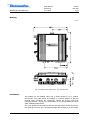
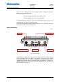
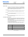
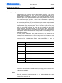
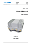
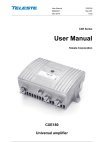
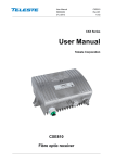
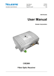
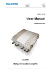
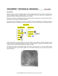
Broadband Cable Networks User Manual 59300148 3.11.2006 AC800 Rev.003 1(14) ACcess Series User Manual Teleste Corporation AC800 Fibre Node Broadband Cable Networks User Manual 59300148 3.11.2006 AC800 Rev.003 2(14) Introduction AC800 is a single active output node with high performance characteristics. The node is based on fixed receiver concept but new features can be added by flexible modular solutions. New automatic functions can be added later in the form of SW or plug-in module. AC800 node features an 862 MHz bandpass, integrated optical receiver and Gallium Arsenide Hybrid technology. Other standard features include built-in return path ingress switch, optimised fibre organiser as well as an efficient surge and ESD protection. WEEE Notice This product complies with the relevant clauses of the European Directive 2002/96/EC on Waste Electrical and Electronic Equipment (WEEE). The unit must be recycled or discarded according to applicable local and national regulations. European Conformity This equipment conforms to all applicaple regulations and directives of European Union which concern it and has gone through relevant conformity assessment procedures. Broadband Cable Networks User Manual 59300148 3.11.2006 AC800 Rev.003 3(14) Housing 8604019 Fig. 1. AC800 housing dimensions – top and side view Installation The AC800 can be installed either into a street cabinet or to an outdoor environment. The node should be installed in a vertical position so that the external cable connectors are underneath. Secure the housing with three mounting brackets – see fig.1 for the positions of mounting brackets as well as other installation dimensions. The cover opens with the hinges to the left. The open cover can be removed by first opening the cover into a 90 degrees angle and the lifting it off the hinges. User Manual 59300148 3.11.2006 Broadband Cable Networks AC800 Rev.003 4(14) Close the lid by tightening the four retaining bolts in a diagonal sequence. Before closing the lid check that nothing is trapped between the lid and the case all case gaskets are in their correct positions A sufficient tightening torque is 3 Nm. Ensure that the lid seats evenly on the rubber gasket. The class of enclosure is IP54. To ground the amplifier housing connect at least 4 mm2 grounding wire (Cu) from a proper earth to the grounding point. Cable connections 8604027 Input port External input / Output port Grounding point Output port 2 Output port 1 Fig. 2. Port locations Underneath the AC800 node there are three cable connection points: external return input/output and two outputs. The amount and function of the actual connectors varies with the chosen configuration. All coaxial outputs have a standard PG11 thread and they accept any KDC type adapter or connector. A suitable length of the cable inner conductor exposed for the connectors is approximately 20 mm (fig. 3). User Manual 59300148 3.11.2006 Broadband Cable Networks AC800 Rev.003 5(14) 8604025 Fig. 3. Centre conductor length Powering The supply voltage of the remote powered amplifier (27...65 V AC or ± 33...90 V DC) can be fed through either output ports (fig. 7 pos. 11, 12) fused with common blade-type 15 ampere fuse (fig. 7 pos. 19). When a cable connection is used for powering, the maximum supply current is 8.0 A. The power intake of the remote powered amplifier may also be done externally via the cable feed-through that is located on the upper left corner of the amplifier. In this case the maximum supply current is 12.0 A. External power can also be fed through the amplifier into the network. Maximum feed-through current is 8.0 A per port. Fibre connections The node can accept two fibre cables. These cables carry forward path and return path optical signals. When feeding the optical cable in the node, a suitable PG11 threaded feed-through adapter type KDO900, is available. Remove the outer ring of the cable gland, thread the installation fibre filaments with connectors through the outer ring (fig. 4 pos. 3), through the sealing insert (fig. 4 pos. 2) and finally through the cable gland (fig. 4 pos. 1). Mount the cable gland on the housing. The fibre filament length inside the fibre organiser is adjusted to sufficient measurement before tightening the outer ring. Use the synthetic locking pins (supplied) to seal up unused holes in the sealing insert. 8606022 1 2 3 Fig. 4. KDO900 adapter components User Manual 59300148 3.11.2006 Broadband Cable Networks AC800 Rev.003 6(14) Fibre installation Fibre installation is a critical procedure and it should be done with carefulness. Incorrect handling of the fibre can result in damage and degraded performance. Example of routing the fibres can be seen in figure 5. Cleaning fibre connectors • For correct optical operation ensure that all optical connectors are cleaned immediately before mating using a suitable optical connector cleaning kit. • If a cleaning kit is not available, wipe the end of the connector using pure isopropyl alcohol (99%) and a lint-free wipe. Dry it with filtered compressed air. Wait until dry to insert connector into the adapter. • When fibre optic connectors are unmated, the optical fibre end faces must be protected from contamination using suitable dust caps. Contamination of fibre end faces will reduce the performance of the optical fibre and could ultimately cause failure of the system. Contamination could also damage the fibre end faces when the connectors are mated. DANGER! Do not look into the optical connector of the return transmitter with power applied. Laser light, visible or invisible, can seriously injure eyes or even cause blindness. Broadband Cable Networks User Manual 59300148 3.11.2006 AC800 Rev.003 7(14) The node contains an internal fibre organiser. Figures 5 and 6 illustrate the fibre organiser and the turnable connector panel. Install optical fibres on the fibre organiser, using the routing guides provided. Route the installation fibre filaments (external fibre optic cables) clockwise and the fibre pigtails (Access units) counter-clockwise. 8604092 Fig. 5. Routing fibres – typical configuration Broadband Cable Networks User Manual 59300148 3.11.2006 AC800 Rev.003 8(14) The connector panel manages up to three fibre optic adapters. Connectors and adapters are held in place in the connector panel by universal holders. 8604100 Fig. 6. Turnable connector panel User Manual 59300148 3.11.2006 Broadband Cable Networks AC800 Rev.003 9(14) Connectors and plug-in slots 8604118 5 17 6 7 15 18 8 4 14 1 9 13 2 10 3 16 19 12 19 11 Fig. 7. AC800 plug-in placement 1) 2) 3) 4) 5) 6) 7) 8) 9) Integrated receiver Optical power DC voltage test point Indicator for optical input power Input attenuator Interstage attenuator Interstage equaliser Slot for element management transponder module Output diplex filter Output test point, -20 dB directional coupler *) See chapter ‘Jumper settings’ 10) 11) 12) 13) 14) 15) 16) 17) 18) 19) Output module RF output 1 RF output 2 External return path input / output jumper *) Return input module slot Test signal injection point, -20 dB transformer External return input / output Return path transmitter OMI test point Fuse(s) Broadband Cable Networks User Manual 59300148 3.11.2006 AC800 Rev.003 10(14) Jumper settings The function of external return input / output (fig. 7 pos. 16) is selected with a jumper (fig. 7 pos. 13). The jumper can be operated in three different positions. The positions are ‘normal use’, ‘ext. input’ and ‘ext. output’. The jumper positions are displayed in the protective covering inside the amplifier housing (see fig. 7). The node is configured at the factory for ‘normal use’. Normal use In ‘normal use’ configuration the return signals from output ports 1 and 2 are routed to return path transmitter. The external Input / output port is not in use. Ext. input In ‘ext. input’ configuration the return signal from external return input / output port is routed to return path transmitter. Ext. output In ‘ext. output’ configuration the return signals from output ports 1 and 2 are routed to external Input / output port. Forward path / Optical receiver The optical receiver is integrated within the AC800 and will accept both 1310 and 1550 nm wavelength optical inputs. The optical receiver provides both LED indicator and DC voltage test point for received optical power to quickly determine operation of the unit. The output stage uses a GaAs hybrid to improve RF performance over the entire 47 to 862 MHz passband. A diplex filter is selected during configuration according to the preferred frequency split. The distribution path, through the use of plug-in output modules, can be set up for a variety of output configurations. Refer to the ‘Table 1. Output modules’. Output module Description AC6112 1/12 dB tap AC6116 1/16 dB tap AC6120 0 dB output module AC6124 Two-way splitter AC6128 2/9 dB tap Table. 1. Output modules Broadband Cable Networks User Manual 59300148 3.11.2006 AC800 Rev.003 11(14) Optical input power Optical input power can be measured from the optical power DC voltage test point (fig. 7 pos. 2). The test point DC voltage is directly proportional to optical input power in mW e.g. 1.0 V corresponds to 1.0 mW average optical power. In case of a 1310 nm wavelength selection the input power in dBm (W) can be calculated by the formula Pin (dBm)=10*log (UTP) When using 1550 nm transmitters the input power in dBm (W) can be calculated by the formula Pin (dBm)=10*log (UTP*(0.85/0.95)). Do not connect any voltage to the test point or short circuit it to ground. Use a voltage meter with an input resistance higher than 100 kohms. Gain control Use an input attenuator plug-in to get appropriate RF level. Attenuators of the JDA900 series type ranging from 0 dB to 20 dB in 1 dB steps are available. The attenuator value depends not only on the optical input level but also on the OMI. Refer to the ‘Table 3. Input attenuator selection guide’. The mainboard provides a LED indicator (fig. 7 pos. 3) which gives a visual indication of the optical input power. LED on AC800 Condition Yellow Optical input power is below -10.0 dBm Green Red Optical input power is within the nominal range (-10.0…+3.0 dBm) Optical input power exceeds +3.0 dBm Table 2. LED indicator on AC800 Forward path adjustment The following are instructions to be used for a normal adjustment procedure. This procedure assumes that the output module and diplexer that are specified in the network plan are installed. 1. Do not connect fibres or apply power before all the adjustments described below have been made. 2. Test the optical input power present on the fibre service cable using an optical power meter. The AC800 integrated optical receiver power input range is -5 dBm to +1 dBm. 3. Install an input attenuator (fig. 7 pos. 4) to get appropriate RF level. Attenuators of the JDA900 series ranging from 0 dB to 20 dB in 1 dB steps are available. The attenuator value depends not only on the optical input level but also on the optical receiver type and the OMI. Refer to the ‘Table 3. Input attenuator selection guide’. User Manual 59300148 3.11.2006 Broadband Cable Networks Opt. input level (dBm) 2 1 0 -1 -2 -3 -4 -5 Attenuator (4% OMI) JDA914 JDA912 JDA910 JDA908 JDA906 JDA904 JDA902 JDA900 AC800 Rev.003 12(14) Attenuator (5% OMI) JDA916 JDA914 JDA912 JDA910 JDA908 JDA906 JDA904 JDA902 Table 3. Input attenuator selection guide 4. Install the interstage attenuator (fig. 7 pos. 5) according to wanted output level. The network plan should specify exact signal levels. Refer to the table below. Output level (dBμV) 110 109 108 107 106 … Interstage attenuator (dB) JDA900 JDA901 JDA902 JDA903 JDA904 … Table 4. Interstage attenuator selection guide 5. Install the interstage equaliser (fig. 7 pos. 6) according to network plan. The network plan should specify exact signal values. 6. Apply the power. 7. Connect the fibre(s). 8. The optical receiver may need fine tuning at this point. To fine tune use the interstage attenuator (fig. 7 pos. 5) to set the output level equal to your reference. Before the fine tune, allow the unit to reach its normal operating temperature (approx. 10 min). User Manual 59300148 3.11.2006 Broadband Cable Networks AC800 Rev.003 13(14) Return path / Optical return transmitters Optional return path operation requires plug-in diplex filters (fig. 7 pos. 8) and optical return transmitters (fig. 7 pos. 17) of various values. The diplex filter is selected during configuration according to the preferred frequency split. The available diplex filter types are CXF030 (30/47 MHz), CXF042 (42/54 MHz), CXF050 (50/70 MHz) and CXF065 (65/85 MHz). It is also possible to order the node without return path operation, in which case the diplex filter is replaced by forward path jumper (CXF000). An optional low-pass filter (LPF) on the RF return path works in conjunction with the diplex filter to provide additional rejection of any forward path signals that may be present at the return path input. The LPF (AC621x) plugs into the return input module slot (fig. 7 pos. 14) and is selected according to the frequency split. The return path attenuator slot may also be equipped with an ingress blocker (AC6223). An ingress blocker on the RF return path filters out the lowest frequency band of the return path. Lower ingress level guarantees the safe operation of the EMS transmission and prevents the overloading of return path laser transmitter. To meet present and future return path requirements, the AC800 can be configured with one of ten optical return transmitters. The return path transmitters are available either in 1310 nm Fabry-Perot, 1310 nm DFB or 1550 nm DFB versions. In addition the platform can be equipped with CWDM transmitters. The CWDM lasers deploy eight wavelengths in range of 1470…1610 nm. Type Description AC6840 FP 1310 nm AC6845 DFP 1310 nm AC6847 DFP, CWDM 1470 nm AC6849 DFP, CWDM 1490 nm AC6851 DFP, CWDM 1510 nm AC6853 DFP, CWDM 1530 nm AC6855 DFP, CWDM 1550 nm AC6857 DFP, CWDM 1570 nm AC6859 DFP, CWDM 1590 nm AC6861 DFP, CWDM 1610 nm Table 5. Optical return transmitters Gain control Set driving level for the laser by installing appropriate attenuator in the transmitter. Attenuators of the JDA900 series type ranging from 0 dB to 20 dB in 1 dB steps are available. Pilot The pilot generator level corresponds to 4% OMI. Available pilot signal frequency 4.5 MHz or 6.5 MHz can be controlled with a DIP switch on the module’s front panel (fig. 8). User Manual 59300148 3.11.2006 Broadband Cable Networks AC800 Rev.003 14(14) ac6840k Fig. 8. AC6840 DIP switch positions Laser With the DIP switch it is possible to reduce nominal optical power by 1 dB. But OMI is also changed. However the product specifications are valid only when using the nominal power. Return path adjustment Inject a signal of known power (20 dB higher compared to return path input level) into the test signal injection point (fig. 7 pos. 15) in the node. The level of return signal can be measured from the optical transmitter’s OMI test point (fig. 6 pos. 18). In the front panel label of the return transmitter is described the driving level at the OMI test point that gives 4% OMI / channel. The return signal level should be adjusted to match this level, which is specific for each unit. For other OMI values, the needed adjustment setting can be calculated from the formula: 20 x log (new OMI% / 4%) Depending on the nature of the return signal, the input level can be measured as follows: • When using a reference or test signal, the level of the carrier signal is measured from the test point and it is adjusted to a value shown in the unit’s label or calculated from it. • When using a digital, noise like signal, the spectrum analyser’s noise marker is adjusted to the same bandwidth as the digital signal has and the level is adjusted to the value shown in the unit’s label or calculated from it. Utilising remotely controlled ingress switch allows the operator to isolate problems in return path and take corrective actions. The return path signal can either be cut off (i.e. signal is attenuated more than 45 dB) or be attenuated by 6 dB. As default factory setting the ingress switch is set to 0 dB position. Since homes may not always be connected to return path services, the return path RF signal should be cut off by the management unit. Once connected, the ingress switch should be set to 0 dB position.