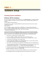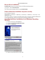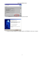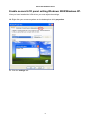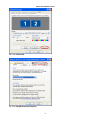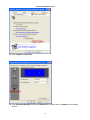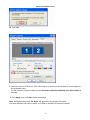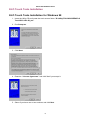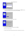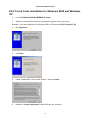
1
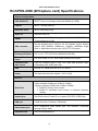
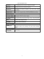
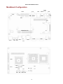
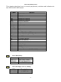
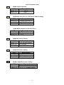
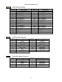
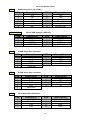
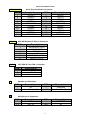
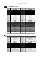
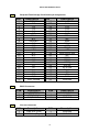
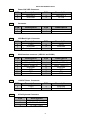
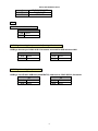
User's Manual
RichPOS-2000 with FIR-ULV600~1G-DVR main board, 8.4 & 14.1 inch LCD’s
Federal Communications Commission (FCC)
This equipment has been tested and found to comply with the limits for a Class A digital device,
pursuant to Part 15 of the FCC Rules. These limits are designed to provide reasonable
protection against harmful interference in a residential installation. This equipment generates,
uses, and can radiate radio frequency energy and, if not installed and used in accordance with
the instructions, may cause harmful interference to radio communications. However, there is no
guarantee that interference will not occur in a particular installation. If this equipment does
cause harmful interference to radio or television reception, which can be determined by turning
the equipment off and on, the user is encouraged to try to correct the interference by one or
more of the following measures:
Reorient or relocate the receiving antenna.
Increase the separation between the equipment and the receiver.
Connect the equipment to an outlet on a circuit different from that to which the receiver is
connected.
Consult the dealer or an experienced radio/TV technician for help.
Shielded interconnect cables and shielded AC power cables must be employed with this
equipment to insure compliance with the pertinent RF emission limits governing this device.
Changes or modifications not expressly approved by the system’s manufacturer could void the
user’s authority to operate the equipment.
Declaration of Conformity
This device complies with part 15 of the FCC Rules. Operation is subject to the following two
conditions:
1. This device may not cause harmful interference, and
2. This device must accept any interference received, including interference that may cause
undesired operation.
Important Safety Information
SAFETY INSTRUCTIONS
1.
2.
3.
4.
5.
6.
7.
Please read these safety instructions carefully.
Keep this User’s Manual for later reference.
Don’t use liquid or spray detergent for cleaning. Use only a moistened sheet or cloth.
For pluggable equipment, the socket-outlet should be installed near the equipment and
should be easily accessible.
Keep this equipment from extreme humidity areas.
Lay this equipment on a stable surface when installing.
Do not leave this equipment in a non-air conditioned environment, or in a storage
temperature above 60∘C. Such conditions may damage the equipment.
10. Place the power cord so that it will not be stepped on. Do not place anything over the
power cord. The power cord must be rated for the product and for the voltage and current
marked on the product’s electrical ratings label. The voltage and current rating of the cord
should be greater than the voltage and current rating marked on the product.
11. All cautions and warnings on the equipment should be noted.
12. If the equipment is not used for a long time, disconnect the equipment from the mains to
avoid damage.
14. Never open the equipment. For safety reasons, qualified service personnel should only
open the equipment.
15. If one of the following situations arises, get the equipment checked by service personnel:
a. The Power cord or plug is damaged.
b. Liquid has penetrated the equipment.
c. The equipment has been exposed to extreme moisture conditions.
d. The equipment does not work well or you cannot get it work according to the user’s
manual.
e. The Equipment has been dropped and damaged.
f. The equipment has obvious signs of damage.
Copyright
The information in this guide is subject to change without prior notice.
The manufacturer shall not be liable for technical or editorial errors or omissions contained
herein, nor for incidental or consequential damages resulting from the furnishing, performance,
or use of this material.
This manual contains information protected by copyright. No part of this manual may be
photocopied or reproduced in any form without prior written consent from the manufacturer.
© 2005 All rights reserved.
The software described in this guide is furnished under a license agreement or nondisclosure
agreement. The software may be used or copied only in accordance with the terms of the
agreement.
Product names mentioned herein may be trademarks and/or registered trademarks of their
respective companies.
First Edition December 2005
Table of Content
Chapter 1
Introduction
1
1
RichPOS-2000 Characteristics .............................................................................................. 1
How to Use This Manual ....................................................................................................... 2
A Visual Tour of RichPOS-2000 ............................................................................................ 3
8.4” RichPOS-2000 ........................................................................................................ 4
14.1” RichPOS-2000 ...................................................................................................... 4
Single LCD Panel Holder................................................................................................ 5
Dual LCD Panel Holder .................................................................................................. 5
What comes with RichPOS-2000 ................................................................................... 6
RichPOS-200 Dimensions.............................................................................................. 7
Connector Panels .................................................................................................................. 9
Font Connector Panel..................................................................................................... 9
Rear Connector Panel .................................................................................................. 10
Chapter 2
Hardware Setup
11
11
RichPOS-2000 Assembly .................................................................................................... 11
Hard Disk Drive Installation .......................................................................................... 11
60keys Keyboard Installation........................................................................................ 13
14” 1st TFT-LCD Display Installation............................................................................ 14
8.4” 2nd TFT-LCD Display Installation ......................................................................... 16
VFD Customer Display Installation............................................................................... 19
MCR Parameter Modification ....................................................................................... 22
Cash Drawer Installation .............................................................................................. 23
CMOS Setup ....................................................................................................................... 23
Chapter 3
Software Setup
24
24
Operating System Installation.............................................................................................. 24
Windows 98 SE installation .......................................................................................... 24
Windows 2K/XP installation.......................................................................................... 25
Device Driver Installation ..................................................................................................... 26
Please follow this installation sequence exactly. ................................................................. 26
Intel Chip Set Driver Installation for all Windows Operating Systems ................................. 26
VGA Driver Installation ........................................................................................................ 28
852GM driver installation Windows 98 & ME ............................................................... 28
852GM driver installation Windows 2000 & XP ............................................................ 30
Enable second LCD panel setting Windows 2000/Windows XP. ................................. 32
LAN Driver Installation......................................................................................................... 36
Realtek LAN Driver Installation Windows 98 ................................................................ 36
Realtek LAN Driver Installation Windows 2000 and Windows XP................................ 38
Audio Driver Installation....................................................................................................... 39
Audio Driver Installation for all Windows Operating Systems....................................... 39
USB Driver Installation ........................................................................................................ 41
USB 2.0 Installation for Windows 98 & ME .................................................................. 41
USB 2.0 Installation for Windows 2000 and XP ........................................................... 44
ELO Touch Tools Installation .............................................................................................. 45
ELO Touch Tools Installation for Windows 98.............................................................. 45
ELO Touch Tools Installation for Windows 2000 and Windows XP ............................. 47
ELO Control Panel........................................................................................................ 50
TouchKit Tools Installation .................................................................................................. 53
TouchKit Tools Installation for all Windows Operating Systems .................................. 53
TouchKit Control Panel................................................................................................. 56
Wireless LAN Driver Installation for all Windows Operating Systems (Optional) ......... 57
Chapter 4
Specifications
58
58
RichPOS-2000 (W/O Capture card) Specifications ............................................................. 58
RichPOS-2000 (W/Capture card) Specifications ................................................................. 60
MainBoard Configuration..................................................................................................... 62
I/O board Configuration ....................................................................................................... 72
9000CB0810 I/O Board Pin Definition .......................................................................... 72
Chapter 5
Troubleshooting
76
76
Power is on, but there is no Panel Display ................................................................... 76
Cannot Detect HDD...................................................................................................... 77
Touch Panel Does not Work......................................................................................... 77
ELO Touch Panel Cannot Calibrate Correctly.............................................................. 77
PS/2 Keyboard is not Functioning Normally ................................................................. 77
MCR is not Functioning Properly.................................................................................. 78
VFD Display is not Functioning Properly ...................................................................... 78
LAN is not Functioning Properly ................................................................................... 78
COM1, COM2, COM5, COM6 are not Functioning Properly ........................................ 78
Cash Drawer Port is not Functioning Properly ............................................................. 79
USB device is not Functioning Properly ....................................................................... 79
FIR-ULV600-DVR Main Board
Chapter 1
Introduction
RichPOS-2000 Characteristics
•
RichPOS-2000 uses a high speed processor capable of handling a high capacity of
data efficiently.
•
RichPOS-2000 solid quality Aluminum housing distinguishes it from ordinary plastic
housings.
•
The RichPOS-2000 touch terminal all-in-one is a robust, fanless design and is suitable
for a multitude of business types.
•
RichPOS-2000 is very suitable for the retail market environment.
•
The LCD panel can be tilted at multiple angles for operator ease of use.
•
RichPOS-2000 functionality extends far beyond the standard setup. RichPOS-2000
can be adapted for a variety of uses with the addition of any of the following options:
Capture Card, Magnetic Card Reader, VFD/LCD customer display and Cash drawer,
Hard disk, Modem, LAN, Audio devices, Compact Flash, Camera, Biometric reader and
a wide variety of USB devices (all available upon request).
•
RichPOS-2000 security is designed to prevent data theft. The RichPOS-2000 system
can be totally diskless or may be equipped with an internal 3.5” HDD. Data Backup can
be constrained to Backup Servers in a network environment, or to (optional) removable
external Storage devices making it hard to copy data without authority.
•
RichPOS-2000 is a fanless solution, which utilizes the solid aluminum housing to
dissipate any excess heat.
•
Additionally the aluminum casing also assures compliance to vigorous EMI radiation
testing.
1
FIR-ULV600-DVR Main Board
How to Use This Manual
This manual contains all the information you need to set up and use RichPOS-2000. In addition,
you can also consult the manuals for the operating system and any additional hardware manuals
for peripherals that you may have added.
Chapter 1
Provides an introduction to RichPOS-2000 and this manual.
Chapter 2
Provides all necessary information for all hardware setup.
Chapter 3
Provides the necessary information for installing the video drivers, touch screen
tools, audio, USB and LAN drivers.
Chapter 4
Lists all RichPOS-2000 specifications and Information for the main board
configuration.
Chapter 5
Provides information for troubleshooting the RichPOS-2000.
2
FIR-ULV600-DVR Main Board
A Visual Tour of RichPOS-2000
Before you start, take a few moments to become familiar with RichPOS-2000.
Acrylic Top Cover
Memory Heatsink
Rear I/O Panel
Front I/O Panel
Internal I/O Connector Board
9000CB0810
Aluminum Base
HDD
Front I/O Door
HDD Case
Keyboard Connector Board
9000CB0830
RichPOS-2000
3
FIR-ULV600-DVR Main Board
8.4” RichPOS-2000
Inverter
LCD Panel
A/D Board
MCR Connector Board
Touch Panel
Aluminum Back Cover
OSD Keypad
PC Film
Acrylic Front Cover
Panel Holder
Hinge Holder
Blanking Covers
14.1” RichPOS-2000
Touch Panel
Inverter
LVDS Converter Board
MCR Connector Board
Aluminum Back Cover
Hinge Holder
PC Film
Blanking Covers
Acrylic Front Cover
Panel Holder
LCD Panel
4
IC Card Reader Connector Board
FIR-ULV600-DVR Main Board
Single LCD Panel Holder
Hinge Cover
Cable Cover
LCD Mounting Post
Dual LCD Panel Holder
Secondary LCD
Mounting Post
5
FIR-ULV600-DVR Main Board
What comes with RichPOS-2000
The following items are optional:
The following items are standard with
RichPOS-2000:
•
Main system with 14” or 8” LCD
panel
•
Power adapter
•
User’s guide
•
FIR-ULV600-DVR motherboard
user’s guide
•
Motherboard chipset driver CD
•
AC power cord
14” RichPOS -2000
With VFD customer display
•
8.4” TFT-LCD
Display
•
60 keys keyboard with
Magnetic Card Reader
(MCR).
•
VFD customer display
•
Wireless LAN
Customer
14” RichPOS-2000
With 8.4” TFT-LCD Panel customer display
6
FIR-ULV600-DVR Main Board
RichPOS-200 Dimensions
7
FIR-ULV600-DVR Main Board
8
FIR-ULV600-DVR Main Board
Connector Panels
Font Connector Panel
PWR PWR K/B
LED SW
USB
3&4
VGA
I/O Port
Connector Type
Description
USB 3 & 4
USB Type A
VGA
VGA Connector
K/B
PS/2 Keyboard
Connector
Power Switch
Tactile Switch
Power LED
These are USB version 2.0 ports and can be used
to connect most USB devices.
The VGA port is for use with an external LCD or
CRT monitor.
The K/B port for an external keyboard.
PWR SW
PWR LED
ATX power switch function.
9
FIR-ULV600-DVR Main Board
Rear Connector Panel
COM5
USB1
Power
LINE
IN
LAN
COM6
Cash
Drawer
COM4
LINE
OUT
COM2
COM1
LPT1
I/O Port
Connector Type
Description
Power
Cash Drawer
DC Power Connector
RJ11 Connector
Line Out
LAN
Earphone Connector
LAN RJ45 Connector
COM1、COM2
D-sub Connector
COM4
VFD/ COM4 RJ45
Connector
Connects RichPOS-2000 to the power supply.
Cash Drawer Connector, 12 V Actuation support
for solenoid.
The audio port is for speakers.
The LAN port is used to hook RichPOS-2000 to a
local area network.
The serial ports COM1/COM2/COM5/COM6 can
be used to connect serial devices such as a serial
printer or a fax/modem. (Note 1)
This RJ45 port is used to attach a VFD customer
display or may be used as an additional serial port.
USB 1
USB A Connector
This is a USB version 1.1 for additional devices
COM5、COM6
Note1: Com5 & Com6 ports will be assigned with DVR Application
10
FIR-ULV600-DVR Main Board
Chapter 2
Hardware Setup
RichPOS-2000 Assembly
Please make sure that the power supply is disconnected when making any hardware changes to
RichPOS-2000.
Hard Disk Drive Installation
A standard RichPOS-2000 comes without a hard disk drive (HDD), unless it is pre-requested.
Installing a HDD
1. Turn off power and remove power cable from main unit.
2. Remove two screws
from the HDD cover
3. Place HDD on the
HDD cover with 4
screws.
11
FIR-ULV600-DVR Main Board
4. Connect the existing 40pin ribbon cable and 4pin power cable to the HHD
5. Screw the cover back
to the unit with two
screws.
6. Connect the main unit power.
Note: If the HDD does not work normally, please refer to troubleshooting
12
FIR-ULV600-DVR Main Board
60keys Keyboard Installation
Installing60Keys Keyboard
1. Turn off power and remove power cable from RichPOS-2000.
2. The Keyboard is install or
replace at the vertical
direction
Keyboard
Socket
There are two types of
keyboard available , one
include USB 4 ports Hub,
this is reserved for customer
specific devices the other is
without USB Hub function,
please refer to 9000PB0810
I/O Board Jumper setting
USB2 signal routing Jumper
J2 and J3
13
FIR-ULV600-DVR Main Board
14” 1st TFT-LCD Display Installation
Installing 1st VGA Display
1. To remove60 Key’s
keyboard
2. To remove 2 screw of the
cover from the neck
3. Insert 1st LCD Panel Cable
through the neck and to
Case bottom
LCD Cable
14
FIR-ULV600-DVR Main Board
4. Screw back the front cover
with 2 screws
5. Connect the display cable to 36
pin SCSI II connector
36 PIN SCSI II connector
for 1st LCD cable
6. Put K/B back to the system
and Torn on system power
15
FIR-ULV600-DVR Main Board
8.4” 2nd TFT-LCD Display Installation
Installing 2nd VGA Display
1. To remove60 Key’s
keyboard
2. To remove 2 screw
of the cover from
the neck.
16
FIR-ULV600-DVR Main Board
3. Insert VGA Cable
through the neck to
Case bottom
VGA Cable
4. Mount 2nd VGA
Display holder to
the neck with 4
screws
5. Screw back the
front cover with 2
screws and put K/B
back to the system
17
FIR-ULV600-DVR Main Board
6. connect 2nd VGA
display cable to
26pin SCSI II
connector
26 PIN SCSI II connector
for VGA cable
18
FIR-ULV600-DVR Main Board
VFD Customer Display Installation
An optional VFD customer display can be installed on the back of RichPOS-2000.
Rear view with VFD attached.
Installing a VFD
1. Turn off system power.
2. Make sure that JP8 and JP9 on the M/B are set correctly. It is important to note that the
supply voltage for the customer display has been set to +12V, which is for VFD type. If an
LCD customer display is chosen, please change it to +5V through JP8 on M/B. Please
refer to page 11 of FIR-ULV600-DVR motherboard manual COM4 Voltage selection and
COM4 mode selection.
3. To remove60 Key’s
keyboard
19
FIR-ULV600-DVR Main Board
4. To remove 2 screw of the
cover from the neck.
5. Insert the VFD cable
through the neck to the
button
VFD Cable
6. Mount VFD module to
the neck with 4 screws
20
FIR-ULV600-DVR Main Board
7. Screw back the front
cover with 2 screws and
put K/B back to the
system
8. Connect VFD cable to COM4
port
RJ45 connector
9. Turn on system power.
Note: If the VFD does not display correctly after an application is loaded, please refer to troubleshooting.
21
FIR-ULV600-DVR Main Board
MCR Parameter Modification
This option is for users who need to customize the MCR parameters for a particular task.
Some of the useful parameters include:
The selection of country code, other than the default English.
The choice of track combinations.
The preamble/post amble codes.
The MCR parameters can be modified by using the supplied utility program.
The utility can be found on the CD that came with your system in the “Utilities” folder. The
program name is msr_v12_win.zip.
If you are upgrading and earlier system to include our MCR reader, then this utility can be located
on our website at http://www.firich.com.tw/tech_drivers.htm in the section labeled as “MSR Utility”.
Unzip this file onto your system hard disk, in a folder of your choice.
It will also create 3 subfolders named Disk1, Disk2, and Disk3.
Change to the folder “Disk1” and run the “Setup.exe” program, and follow the simple onscreen
instructions.
When the installation finishes, you will find that a new folder has been created in your “Program files”
folder, labeled as “Decoder” with a subfolder named “S64 Decoder”.
Now change folder to C:\Program Files\Decoder\S64 Decoder and run the program named
“S64_cfg.exe”.
When the program has loaded please select the Magnic_Reader menu item as in the following
picture. By using the 3 top items listed; Interface, Communication and Miscellaneous, you will
be able to alter many of the parameters associated with the MCR unit.
When you have finished your modifications and are sure that they are set exactly how you want
them to be, just click on the menu item Transmit to download the new parameter to the MCR unit.
Please refer to the Help menu for any further assistance.
22
FIR-ULV600-DVR Main Board
Cash Drawer Installation
Before connecting the cash drawer to the RichPOS-2000, please make sure the drive voltage
and cable pin assignment of the cash drawer matches the definition of the cash drawer port of
RichPOS-2000. Please refer to page 21 in the motherboard manual for more information on the
Cash Drawer.
Plug cash drawer cable into cash drawer port.
Note: If the cash drawer cannot be detected by the system, please refer to troubleshooting.
Up to two cash drawers may be driven from this port. Driving voltage of the solenoid is DC+12V.
I/O port 280h is used for drawer operation. A test program is supplied, for Linux and Windows,
source code of which is available on request by software developers.
Hardware logic is as follows.
To open drawer1, write 01h to port 280h, wait 200 msec, then write 00h to turn off the drive.
To open drawer2, write 02h to port 280h, wait 200 msec, then write 00h to turn off the drive.
To test for drawer open, read port 281h, if bit 0=1 then drawer is open, if bit 0=0 drawer is closed.
CMOS Setup
Please refer to the FIR-ULV600-DVR M/B User's Manual Chapter 4 for a detailed description of
the BIOS CMOS setup.
23
FIR-ULV600-DVR Main Board
Chapter 3
Software Setup
Operating System Installation
Windows 98 SE installation
As it is not possible to attach an IDE CDROM drive to the RichPOS-2000 unit, installing Windows
98 SE may appear to be difficult. There are a number of ways in which Windows 98 SE can be
installed.
This is probably the easiest method.
This objective is to create a bootable MSDOS Compact Flash that will include all the required
Windows 98 setup files.
Items required:
A PC or Notebook computer equipped with a CDROM drive, a Compact Flash reader/writer
device, a 128MB or 256MB Compact Flash, a floppy disk drive with an MSDOS boot diskette that
also contains the DOS system utilities “Fdisk” and “Format” programs.
* Real-mode CD-ROM drivers
You will need real-mode CD-ROM drivers loaded so you can access the Windows 98 Second
Edition CD. If you have ever run Windows 98 SE Setup before and have created a Startup Disk,
you can boot and use the CD-ROM drivers included on that disk. If you do not have a Startup
Disk, you will need to run the installation program that came with your CD-ROM hardware.
1. Boot the PC or Notebook from the Floppy diskette
2. Insert the 128MB or 256MB Compact Flash into the reader/writer device
3. Use the Format program to format the Compact Flash as a “bootable” FAT16 volume
4. Copy all files from the floppy to the Compact Flash
5. Create a folder called "W98Flat" on the Compact Flash drive (to create a folder, switch to
the Compact Flash drive letter and type: MD W98Flat
6. Now, switch to the Windows 98 Second Edition CD-ROM drive and to the Win98 directory
7. Then copy the Windows 98 Second Edition Setup files to the folder you just created on the
Compact Flash by typing: Copy *.* < Compact Flash drive letter>\W98Flat
8. After all the files are copied, you may now remove the Compact Flash from the PC
9. Insert the Compact Flash into the RichPOS-2000 (follow instructions earlier in this manual)
10. Modify CMOS BIOS to Boot from Compact Flash
11. Power on the system and the unit should boot MSDOS from the Compact Flash drive
12. At the MSDOS prompt, type FDISK and partition the Hard Disk drive as required
24
FIR-ULV600-DVR Main Board
13. After partitioning is complete, Format the Hard Disk drive
14. At the MS DOS prompt change directory to W98Flat
15. Type Setup and press Enter
16. Follow the onscreen instructions for normal installation of Windows 98 SE
Windows 2K/XP installation
Installing Windows 2K or XP can be performed on the RichPOS-2000 quite simply
Items required:
A USB CDROM drive
1. Attach the USB CDROM drive to RichPOS-2000.
2. In the CMOS setup “Advanced Chipset setup” change the item “USB Device Legacy
Support” to “All Devices” this will allow booting from any USB bootable device.
3. Power on and modify CMOS BIOS settings to enable the USB CDROM to be the first
bootable device (see CMOS setup in the motherboard manual)
4. Insert the 2K or XP CDROM disk into the drive
5. Reboot the system
6. The RichPOS-2000 will boot from CDROM drive and automatically start the setup
programs
7. Follow the onscreen instructions for normal installation of 2K or XP
25
FIR-ULV600-DVR Main Board
Device Driver Installation
RichPOS-2000 comes with a variety of drivers for different operating systems.
You will find 1 CD with RichPOS-2000.
The CD has all the necessary drivers to setup RichPOS-2000.
Please follow this installation sequence exactly.
Driver installation sequence:
Chipset Driver -> VGA Driver -> LAN Driver -> Audio Driver -> USB Driver -> Touch Tools -> FIX
COM PORT Tools
The reason to follow our sequence is that IRQ settings will be changed by Windows 2000 and XP
to non supported values, and you may encounter unnecessary problems later.
Intel Chip Set Driver Installation for all Windows Operating
Systems
1. Insert the CD into your CD ROM Drive.
2. Locate D:\ULV600.DVR\CHIPSET\INF folder
3. Double click Setup.exe
4. Click Next.
5. Read the License Agreement and click Yes.
26
FIR-ULV600-DVR Main Board
6. Click Next and the drivers for the Intel Chip set will install.
7. When the 'Setup COMPLETE' message appears click Finish to restart your computer.
27
FIR-ULV600-DVR Main Board
VGA Driver Installation
FIR-ULV600-DVR uses only one chipset “852GM” that is capable of driving a single or dual panel
display. Only one driver needs to be installed.
852GM driver installation Windows 98 & ME
1. Locate the VGA folder on the utilities CD.
2. Open D:\ULV600.DVR\VGA\INTEL\win9x folder
3. Run setup.exe.
4. Select Next to continue.
5. Read the License Agreement and click Yes.
28
FIR-ULV600-DVR Main Board
6. Click Finish to complete the installation procedure and restart the system.
7. When entering Windows, Windows will find new hardware.
Insert Disk
Open D:\ULV600.DVR\GRAPHIC\INTEL\WIN9X\WIN9X\ikch8xx.cat folder
Click OK
29
FIR-ULV600-DVR Main Board
852GM driver installation Windows 2000 & XP
1. Open D:\ULV600.DVR\VGA\INTEL\WIN2K_XP folder.
2. Run setup.exe
3. Select Next to continue.
4. Read the License Agreement and click Yes.
30
FIR-ULV600-DVR Main Board
5. Click Finish to complete the installation procedure and restart the system.
31
FIR-ULV600-DVR Main Board
Enable second LCD panel setting Windows 2000/Windows XP.
After you have installed the VGA driver you must adjust the settings.
.
10. Right click your mouse anywhere on the desktop then click properties.
11. Click the settings tab.
32
FIR-ULV600-DVR Main Board
12. Click Advanced.
13. Click Intel(R) Extreme Graphics.
33
FIR-ULV600-DVR Main Board
14. Click Graphics Properties.
15. Click Extended Desktop and select Notebook for primary device, monitor for secondary
device.
34
FIR-ULV600-DVR Main Board
16. Click OK.
8. Select the second LCD panel. This is done either by clicking on the number 2 or selecting from
the dropdown menu.
For the second LCD panel make sure that Extend my Windows desktop onto this monitor is
selected.
9. Click Apply then click OK to finish the settings.
Note. During boot sequence “No Sync” will appear on the second LCD panel.
The boot sequence can take a minute or so when a second LCD panel is installed.
35
FIR-ULV600-DVR Main Board
LAN Driver Installation
Realtek LAN Driver Installation Windows 98
1. Open Device Manger in the System Properties.
Select PCI Ethernet Controller
Click Properties
2. Select the General tab.
Click Reinstall Driver.
36
FIR-ULV600-DVR Main Board
3. Select Specifily a location, click path “C:\ULV600.DVR\LAN\Realtek\Win98”
Click Next.
4. Select The updated driver [Recommended].
Click Next.
5. Click Next.
37
FIR-ULV600-DVR Main Board
6. Click Finish.
7. Click Yes to restart your computer.
Realtek LAN Driver Installation Windows 2000 and Windows
XP
After Windows 2000 is installed the Realtek LAN driver will be automatically installed.
38
FIR-ULV600-DVR Main Board
Audio Driver Installation
Audio Driver Installation for all Windows Operating Systems.
1. Open D:\ULV600.DVR\AUDIO\Realtek
2. double click Setup.exe.
3. Select Next to continue.
Note: For Windows 2K. If you receive this warning message, please click Yes to continue.
39
FIR-ULV600-DVR Main Board
Note: For XP If you receive this warning message, please click Continue Anyway.
4. Click Finish and restart the system.
40
FIR-ULV600-DVR Main Board
USB Driver Installation
USB 2.0 Installation for Windows 98 & ME
1. Open Device Manger in the System Properties.
Select PCI Universal Serial Bus
Click Properties
2. Click Reinstall Driver
41
FIR-ULV600-DVR Main Board
3. Click Next
4. Select Search a better driver than the one your device is using now. [Recommended]
Click Next
5. Select Specify a location, click path “C:\ULV600.DVR\USB2.0\INTEL\WIN98_ME”
Click Next
42
FIR-ULV600-DVR Main Board
6. Click Next
7. Click OK
8. click path “C:\ULV600.DVR\USB2.0\INTEL\WIN98_ME”
Click OK
43
FIR-ULV600-DVR Main Board
9. Click Finish
USB 2.0 Installation for Windows 2000 and XP
For Windows 2000, SP4 must be installed for USB 2.0 support.
For Windows XP, SP1 or SP2 must be installed for USB 2.0 support.
Note, with lower version service packs only USB 1.1 is supported. This will be indicated in
the device manager as an exclamation icon (!) beside the USB device.
Following service pack upgrade, it is NOT necessary to install the Intel USB 2.0 driver.
44
FIR-ULV600-DVR Main Board
ELO Touch Tools Installation
ELO Touch Tools Installation for Windows 98
1. Insert the Utility CD and locate the touch screen folder “D:\Utility\TOUCHSCREEN\ELO
Touch\ELO Win 9X_me”.
2. Run Setup.exe
3. Click Next.
4. Read the “License Agreement” and click Yes if you accept it.
5. Select if you have one or two monitors and click Next.
45
FIR-ULV600-DVR Main Board
6. Select the COM port for the monitor. It is recommended that you select COM3 for primary
touch screen and COM4 for second touch screen. Then click Next.
7. Wait until the ELO Touch Tools have been installed.
8. Select View ELO touch screen control panel and click Finish.
10. Click Yes to restart the system.
11. After the system finishes rebooting follow the directions to calibrate ELO Touch Tools.
46
FIR-ULV600-DVR Main Board
ELO Touch Tools Installation for Windows 2000 and Windows
XP
1.
Locate D:\Utility\TOUCHSCREEN\ELO Touch
2.
Select the relevant ELO folder for the operating system that you are using.
Example. If you are installing for a Windows 2000 or XP then select Elo Touch 2K_XP
3.
Run Setup.exe
4.
Click Next
5.
Check “Install serial Touch screen Drivers.” And Click Next.
6.
Read the “License Agreement” and click Yes if you accept it.
47
FIR-ULV600-DVR Main Board
7.
Select “Auto-detect Elo devices.” and click Next.
8.
Select the COM port for the touch monitor. It is recommended that you select COM3 for
the touch screen, as this port is internally configured for touch operation.
9.
Wait until the ELO Touch Tools have been installed.
48
FIR-ULV600-DVR Main Board
10. Select View ELO touch screen control panel and click Finish.
IT MAY BE NECESSARY TO RESTART YOUR COMPUTER TO UTILIZE
YOUR TOUCHSCREEN FEATURES.
11. Click NEXT while this window appears after system finishs rebooting.
12. Click YES to restart your computer again.
After the system finishes rebooting follow the directions to calibrate ELO Touch Tools.
49
FIR-ULV600-DVR Main Board
ELO Control Panel
This section explains the different options in the ELO control Panel.
General tab
The general tab allows you to:
•
Change the COM port your touch screen is set to.
•
Calibrate the touch screen with the Align button.
50
FIR-ULV600-DVR Main Board
Mode tab
The Buttons tab allows you to:
•
Adjust all mouse emulation controls.
•
Change cursor properties
•
Enable or disable right mouse button utility.
Sound tab
The Sound tab allows you to:
•
To change sound properties for ELO touch tools.
51
FIR-ULV600-DVR Main Board
Properties tab
The Diagnostics tab allows you to:
•
View Controller Information.
About tab
The About tab displays Information about ELO Touch systems
52
FIR-ULV600-DVR Main Board
TouchKit Tools Installation
TouchKit Tools Installation for all Windows Operating
Systems
1. Locate D:\Utility\TOUCHSCREEN\TouchKit\Driver
2. Select the relevant eGalax folder for the operating system that you are using.
Example. If you are installing for a Windows 98 system, then select Win9x_Me. If you are
installing under Windows 2000 or XP then select Win2000_XP
3. Run Setup.exe
4. Click Next
5. Click Next
53
FIR-ULV600-DVR Main Board
6. Click Next
7. Click Next
8. Click Next
54
FIR-ULV600-DVR Main Board
9. Click Yes
10. Click Finish to restart your computer again.
After the system finishes rebooting follow the directions to calibrate the Touch screen.
55
FIR-ULV600-DVR Main Board
TouchKit Control Panel
This section explains the different options in the TouchKit control Panel.
General tab
The general tab allows you to:
•
Change the COM port your touch screen is set to.
•
Calibrate the touch screen with the 4 pts Cal button.
56
FIR-ULV600-DVR Main Board
Wireless LAN Driver Installation
Wireless LAN Driver Installation for all Windows Operating
Systems (Optional)
1. Open D:\Utility\Wireless LAN\802.11b folder
2. Run Setup.EXE
3. Click Next
4. Click Next
57
FIR-ULV600-DVR Main Board
Chapter 4
Specifications
RichPOS-2000 (W/O Capture card) Specifications
System Configuration
CPU (BGA 478)
INTEL® Ultra Low Voltage Celeron-M 600MHz (L2:0KB)
Chipset
INTEL® 852GM (GMCH).
Real-time clock
INTEL 82801DB (ICH4)
Super I/O
Winbond 83627HF
DRAM
One 200-pin SODIMM socket supports 200/266/333 DDR SDRAM.
To the maximum of 1GB
VGA controller
On-chip 852GM built-in AGP2.0 4X 3D graphics engine. Shares
system DDR SDRAM, 32MB(max). Supports 18bit/24bit single
pixel or 36bit/48bit dual pixel color LVDS TFT LCD panel.
Primary LCD Panel
8.4” or 14.1” TFT LCD Panel (800X600/1024x768).
Primary Touch
Panel
8.4” ELO 4-wire or 14.1” ELO 5-wire resistive touch panel.
Compact Flash
Disk socket
Type I/II Compact Flash™ Disk. The Flash Disk provides 100%
compatibility with (IDE2) hard disk.
HDD
Internal 3.5” 40GB hard disk drive (or above).
Power
100 watt external power adapter. (12V / 8.33A)
58
FIR-ULV600-DVR Main Board
I/O Port
Serial Port
4 User available COM ports (COM1 & COM2 &COM5&COM6).
2 System assigned COM ports (COM3 & COM4).
¾ COM3 for primary touch screen.
¾ COM4 for secondary touch screen or customer character
display.
Parallel Port
One Bi-directional Parallel Port, supports ECP/EPP (IEEE1284).
USB port
6 USB 2.0 ports (2*Internal, 4*External)
Cash drawer port
RJ11 Single/Dual Cash drawer port ,12V actuation. Controlled
through I/O port 280H
Keyboard Port
One PS/2 keyboard port.
LAN Port
10/100Mbps Ethernet Controller, Realtek RTL8100BL.
VGA Port
Standard VGA Port for second LCD panel.
Audio Port
Integrated Sound Blaster compatible, AC97 Audio Codec. (Realtek
ALC202A)
Optional Features
Customer display
Integrated VFD/LCD customer display.
Program keyboard
with MCR
Integrated 60Key Keyboard with Single/Dual/Triple Track MCR.
FDD
External USB Floppy disk drive.
CD-ROM
External USB CD-ROM drive.
Power Consumption
Power
consumption
40W Idle
(Standard system with secondary LCD panel while accessing
HDD).
Operating temperature
Operating
temperature
0 ℃ ~ 35 ℃
59
FIR-ULV600-DVR Main Board
RichPOS-2000 (W/Capture card) Specifications
System Configuration
CPU (BGA 478)
INTEL® Ultra Low Voltage Celeron-M 600MHz (L2:0KB)
Chipset
INTEL® 852GM (GMCH).
Real-time clock
INTEL 82801DB (ICH4)
Super I/O
Winbond 83627HF
DRAM
One 200-pin SODIMM socket supports 200/266/333 DDR SDRAM.
To the maximum of 1GB
VGA controller
On-chip 852GM built-in AGP2.0 4X 3D graphics engine. Shares
system DDR SDRAM, 32MB(max). Supports 18bit/24bit single
pixel or 36bit/48bit dual pixel color LVDS TFT LCD panel.
Primary LCD Panel
8.4” or 14.1” TFT LCD Panel (800X600/1024x768).
Primary Touch
Panel
8.4” ELO 4-wire or 14.1” ELO 5-wire resistive touch panel.
Compact Flash
Disk socket
Type I/II Compact Flash™ Disk. The Flash Disk provides 100%
compatibility with (IDE2) hard disk.
HDD
Internal 3.5” 40GB hard disk drive (or above).
Power
100 watt external power adapter. (12V / 8.33A)
I/O Port
Serial Port
2 User available COM ports (COM1 & COM2).
2 System assigned COM ports (COM3 & COM4).
¾ COM3 for primary touch screen.
¾ COM4 for secondary touch screen or customer character
display.
Parallel Port
One Bi-directional Parallel Port, supports ECP/EPP (IEEE1284).
USB port
6 USB 2.0 ports (2*Internal, 4*External)
Cash drawer port
RJ11 Single/Dual Cash drawer port ,12V actuation. Controlled
through I/O port 280H
Keyboard Port
One PS/2 keyboard port.
60
FIR-ULV600-DVR Main Board
LAN Port
10/100Mbps Ethernet Controller, Realtek RTL8100BL.
VGA Port
Standard VGA Port for second LCD panel.
Audio Port
Integrated Sound Blaster compatible, AC97 Audio Codec. (Realtek
ALC202A)
Capture Card
4Ch. BNC Composite Video, NTSC/PAL/SECAM auto sensing
Optional Features
Customer display
Integrated VFD/LCD customer display.
Program keyboard
with MCR
Integrated 60Key Keyboard with Single/Dual/Triple Track MCR.
FDD
External USB Floppy disk drive.
CD-ROM
External USB CD-ROM drive.
Power Consumption
Power
consumption
50W Idle
(Standard system with secondary LCD panel while accessing
HDD).
Operating temperature
Operating
temperature
0 ℃ ~ 35 ℃
61
FIR-ULV600-DVR Main Board
MainBoard Configuration
Power
Button
LVDS1
VGA1
USB1
KB/MS
LED
CN5
CN6
J4
JP10
VGA2
CN4
J5
CN10
JP7
JP2
DDR DIMM Socket
Power
J7
J6
MIC SPK
USB2
J3
CF
COM2
COM4
LAN
IDE1
LPT1
COM5
+
COM6
JP11
CN3
CN11
JP8
JP9
CN7
JP6
JP5 COM3+USB
62
COM1
DIO
FIR-ULV600-DVR Main Board
This chapter describes how to connect peripherals, switches and indicators to
the FIR-ULV600-DVR board.
Label
LVDS1
VGA1 & 2
LAN
USB1
USB2
COM1
COM2
COM4
KB_MS1
J4 & J5
J6 & CN3
J7
LPT1
IDE1
CF1
PS_ON1
LED1
CN1
CN2
CN4
CN5
CN6
CN7
CN8
CN10
CN11
JP2
LVDS LCD Panel connector
VGA connector
LAN RJ45 connector
USB dual port connector
USB dual port connector
Serial port connectors
Serial port connectors
Serial port connectors
Keyboard & Mouse connector
Fan connectors
Speaker out connector
MIC in connector
Parallel port connector
Ultra ATA100 Primary IDE connectors
Compact Flash Storage Card Type II connector
Power on Switch
Power LED
PC/104 Plus connector
Digital I/O connector
External switches and indicators
Power output connector
LVDS back light connector
Multi-function connector
+12V DC power connector
Internal Keyboard connector
Serial port connectors (COM5 & COM6)
Clear CMOS Setup
JP1
Short 1-2
(default)*
Short 2-3
JP7
Function
Description
Keep CMOS Setup
(Normal Operation)
Clear CMOS Setup
TFT LCD Voltage ( 5V / 3V ) Setting
JP3
Short 1–2
Short 2–3
Description
3V TFT LCD
5V TFT LCD
63
FIR-ULV600-DVR Main Board
JP8
COM4 Voltage Selection
JP4
Short 1-2
Short 2-4
JP9
Description
+12V
+5V
COM4 Mode Selection for VFD (factory default setting)
JP5
Short 1-2
Short 3-5
Short 4-6
Description
Short CTS-RTS
+12/+5V output
Ground output
COM4 Mode Selection for RS-232 device
JP5
Short 1-3
Short 2-4
JP5
COM2 RI Function Setting
JP6
Short 1-2
Short 3-4
Short 5-6
JP6
Description
RI is +5Volt output
RI function
RI is +12 Volt output
COM1 RI Function Setting
JP7
Short 1-2
Short 3-4
Short 5-6
JP11
Description
CTS
RTS
Description
RI is +5 Volt output
RI function
RI is +12 Volt output
COM5 & COM6 RI Function Setting
PIN
Short 1-2
Short 3-4
Description
RI is +12 Voltage output
RI is +5 Voltage output
64
FIR-ULV600-DVR Main Board
LVDS1
LVDS Function Setting
PIN No.
1
3
5
7
9
11
13
15
17
19
21
23
25
27
29
VGA1
PIN No.
GROUND
CH1 DATA3+
CH1 CLK+
CH1 DATA2+
CH1 DATA1+
CH1 DATA0+
GROUND
CH2 DATA3+
CH2 CLK+
CH2 DATA2+
CH2 DATA1+
CH2 DATA0+
GROUND
LCD power
LCD power
2
4
6
8
10
12
14
16
18
20
22
24
26
28
30
Description
GROUND
CH1 DATA3CH1 CLKCH1 DATA2CH1 DATA1CH1 DATA0GROUND
CH2 DATA3CH2 CLKCH2 DATA2CH2 DATA1CH2 DATA0GROUND
LCD power
LCD power
15 Pin Female Connector
PIN
1
3
5
7
9
11
13
15
VGA2
Description
Description
RED
BLUE
GROUND
GROUND
VCC / NC
NC
HSYNC
DDCCLK
PIN
2
4
6
8
10
12
14
Description
GREEN
NC
GROUND
GROUND
GROUND
DDC DAT
VSYNC
PIN
6
7
8
9
10
Description
DDCCLK
DDCDAT
GROUND
GROUND
GROUND
10 Pin Box Header Connector
PIN
1
2
3
4
5
Description
RED
GREEN
BLUE
HSYNC
VSYNC
65
FIR-ULV600-DVR Main Board
LAN1
RJ45 Connectors (10 / 100M )
PIN
1
2
3
4
5
6
USB1 & USB2
PIN
1
2
3
4
COM1
Description
N/C
N/C
Speed +
Speed Active/LINK +
Active/LINK -
2 Ports USB Connect (USB 2.0)
Description
VCC
DATA0DATA0+
GROUND
PIN
5
6
7
8
Description
VCC
DATA1DATA1+
GROUND
Description
DCD
RXD
TXD
DTR
GROUND
PIN
6
7
8
9
Description
DSR
RTS
CTS
RI
PIN
6
7
8
9
Description
DSR
RTS
CTS
RI
PIN
2
4
6
8
Description
+12/+5V or CTS
GROUND or RTS
DSR
RXD
D-SUB Serial Port Connector
PIN
1
2
3
4
5
COM4
PIN
7
8
9
10
11
12
D-SUB Serial Port Connector
PIN
1
2
3
4
5
COM2
Description
TX+
TXRX+
N/C
N/C
RX-
Description
DCD
RXD
TXD
DTR
GROUND
RJ-45 Serial Port Connector
PIN
1
3
5
7
Description
+12/+5V
GROUND
DTR
TXD
66
FIR-ULV600-DVR Main Board
COM5 & COM6
PIN
1
3
5
7
9
11
13
15
17
19
KB_MS1
Description
(DSR5)
(RTS5)
(CTS5)
(RI5)
GROUND5
(DSR6)
(RTS6)
(CTS6)
(RI6)
GROUND6
Description
KEYBOARD DATA
MOUSE DATA
GROUND
+5V
KEYBOARD CLOCK
MOUSE CLOCK
Description
Rotation Signa
+12V
l Ground
Speaker out Connector
PIN
1
3-5
J7
PIN
2
4
6
8
10
12
14
16
18
20
CPU FAN & Case FAN Connector
PIN
1
2
3
J6
Description
(DCD5)
(RXD5)
(TXD5)
(DTR5)
GROUND5
(DCD6)
(RXD6)
(TXD6)
(DTR6)
GROUND6
Mini DIN Keyboard / Mouse Connector
PIN
1
2
3
4
5
6
J4 & J5
Serial Port Box Header Connector
Description
NC
Line Out (Left)
PIN
2
4-6
Description
GROUND
Speaker Out (Right)
PIN
2
4-6
Description
GROUND
NC
Microphone in Connector
PIN
1
3-5
Description
NC
MIC In
67
FIR-ULV600-DVR Main Board
IDE1
IDE Interface connector
PIN
1
3
5
7
9
11
13
15
17
19
21
23
25
27
29
31
33
35
37
39
41
43
LPT1
Description
RESET#
DATA 7
DATA 6
DATA 5
DATA 4
DATA 3
DATA 2
DATA 1
DATA 0
GROUND
DRQ
IOW#
IOR#
CHRDY
DACK
INTERRUPT
SA1
SA0
HDC CS0#
HDD ACTIVE#
+5V
GND
PIN
2
4
6
8
10
12
14
16
18
20
22
24
26
28
30
32
34
36
38
40
42
44
Description
GROUND
DATA 8
DATA 9
DATA 10
DATA 11
DATA 12
DATA 13
DATA 14
DATA 15
N/C
GROUND
GROUND
GROUND
REV. PULL LOW
GROUND
N/C
PD66 SELECT
SA2
HDC CS1#
GROUND
+5V
N/C
LPT1 Box Header connector
PIN
1
2
3
4
5
6
7
8
9
10
11
12
13
Description
STROBE#
DATA 0
DATA 1
DATA 2
DATA 3
DATA 4
DATA 5
DATA 6
DATA 7
ACKNOWLEDGE
BUSY
PAPER EMPTY
PRINTER SELECT
PIN
14
15
16
17
18
19
20
21
22
23
24
25
26
68
Description
AUTO FORM FEED #
ERROR#
INITIALIZE
PRINTER SELECT IN#
GROUND
GROUND
GROUND
GROUND
GROUND
GROUND
GROUND
GROUND
NC
FIR-ULV600-DVR Main Board
CF1
Compact Flash Storage Card Socket pin assignment
PIN
1
2
3
4
5
6
7
8
9
10
11
12
13
14
15
16
17
18
19
20
21
22
23
24
25
CN2
PIN
26
27
28
29
30
31
32
33
34
35
36
37
38
39
40
41
42
43
44
45
46
47
48
49
50
Description
PULL DOWN
D11
D12
D13
D14
D15
CS3#
N/C
IOR#
IOW#
VCC
IRQ15
VCC
MASTER/SLAVE
N/C
RESET#
IORDY
DREQ
DACK#
ACTIVE#
PDIAG#
D8
D9
D10
GROUND
DGI/O Connector
PIN
1
3
5
CN3
Description
GROUND
D3
D4
D5
D6
D7
CS1#
N/C
GROUND
N/C
N/C
N/C
VCC
N/C
N/C
N/C
N/C
A2
A1
A0
D0
D1
D2
N/C
PULL DOWN
Description
GROUND
DGI/O IN 0
DGI/O OUT 1
PIN
2
4
6
Description
DGI/O OUT 0
+12V
GROUND
PIN
2
4
Description
GROUND
GROUND
Line out connector
PIN
1
3
Description
LINE Out (Left)
LINE Out (Right)
69
FIR-ULV600-DVR Main Board
CN4
Power SW/ LED Connector
PIN
1
3
CN5
PIN
2
4
Description
Description
+12V
GROUND
Back Light enable
PIN
2
4
Description
+12V
GROUND
Description
+5V
USB- (USB2.0)
USB+ (USB2.0)
GROUND
DTR
RTS
RX
PIN
2
4
6
8
10
12
14
Description
+5V
USB- (USB2.0)
USB+ (USB2.0)
GROUND
CTS
TX
DSR
PIN
2
4
Description
GROUND
GROUND
+12V DC Power Connector
PIN
1
3
CN10
Description
Multi-function connector ( USB 2.0 and COM3 )
PIN
1
3
5
7
9
11
13
CN8
Description
LED OFF +
PS ON
LCD Back Light Connector
PIN
1
3
5
CN7
PIN
2
4
Connector
PIN
1
3
CN6
Description
LED ON +
GROUND
Description
+12V
+12V
6 Pin Keyboard Connector
PIN
1
2
3
Description
+5V
KEYBOARD CLOCK
PC KB CLOCK
70
FIR-ULV600-DVR Main Board
4
5
6
KEYBOARD DATA
PC KB DATA
GROUND
J2&J3
KB/MSR and W/IC Card Reader
1-3
2-4
J1
Short
Short
USB2 Signal routing Jumper mode 1 (factory default setting)
USB2 go directory to CON3 SCSI II Connector reserved for USB wireless LAN
3-5
4-6
J2
Short
Short
1-3
2-4
J3
Short
Short
USB2 Signal routing Jumper mode 2
USB2 go via K/B with USB Hub (9000CB0770) and back to CON3 SCSI II Connector
1-3
2-4
J2
Short
Short
3-5
4-6
71
J3
Short
Short
FIR-ULV600-DVR Main Board
I/O board Configuration
The 9000CB0810 board carries the following signals to the main board. Including: LCD, inverter,
COM3, Keyboard, VGA and USB port.
9000CB0810 I/O Board Pin Definition
20
36
15
35
19
1
25
25
14
22
1
18
2
15
17
26
12
12
13
1
CON1
CON3
CON8
9000PB0810
2
1
J1
20
19
2
1
2
1
CON5
1
6
5
CON6
1
J2
1
2
10
9
2
1
26pin SCSI II connector for 2nd LCD Display
PIN No.
1
2
3
4
5
6
7
8
9
10
11
12
13
Description
RED
+12V
GREEN
+12V
BLUE
+12V
DDC DAT
+12V
HSYNC
+12V
VSYNC
GND
DDC CLK
10
P1
6
5
CON7
19
20
CON1
10
9
CON2
2
1
10
4 2
3
1
J3
CON4
1
4
PIN No.
14
15
16
17
18
19
20
21
22
23
24
25
26
72
Description
GND
GND
GND
GND
GND
GND
GND
GND
GND
GND
GND
GND
GND
4
CON9
FIR-ULV600-DVR Main Board
CON2
Connects to the main board VGA port VGA2
PIN No.
1
2
3
4
5
CON3
REDC
DDC DAT
GREENC
DDC CLK
BLUEC
PIN No.
6
7
8
9
10
Description
GND
HSYNC
GND
VSYNC
GND
36pin SCSI II connector for 1st 8.4”, 14” LCD Display
PIN
1
2
3
4
5
6
7
8
9
10
11
12
13
14
15
16
17
18
CON4
Description
Description
TX
RTS
DM-3
GND
PVDD
RX0RX1RX2RX CLKRX3GND
GND
GND
KB-CK
KB-DA
GND
VIN
GND
PIN
19
20
21
22
23
24
25
26
27
28
29
30
31
32
33
34
35
36
Description
DSR
RX
Vcc
DP-3
PVDD
RX0+
RX1+
RX2+
RX CLK+
RX3+
GND
Vcc
GND
Vcc
PC-CK1
PC-DA1
VIN
ON/OFF
LCD LVDS signal connector connects to the main board LVDS1
PIN
1
2
3
4
5
6
7
8
9
10
Description
PVDD
PVDD
RX0RX0+
NC
GND
RX1RX1+
GND
GND
PIN
11
12
13
14
15
16
17
18
19
20
73
Description
RX2RX2+
GND
GND
RX CLKRX CLK+
GND
GND
RX3RX3+
FIR-ULV600-DVR Main Board
CON5
Inverter and K/B signal connector connects to the main board CN6 and CN10
PIN No.
1
2
3
4
5
GND
VIN
VIN
GND
ON/OFF
Description
PIN No.
DM-1
DP-1
DM-0
DP-0
Vcc
6
7
8
9
10
Description
DSR
TX
RX
NC
RTS
60Keys Keyboard signal connector
PIN
1
2
3
4
5
6
7
8
9
10
CN8
6
7
8
9
10
Description
COM3/USB x2 signal connector connects to the main board CN7
PIN No.
CON7
PIN No.
Vcc
KB-CK
PC-CK
KB-DA
PC-DA
1
2
3
4
5
CON6
Description
Description
GND
GND
DM-31
DP-31
DM-00
DP-00
PC-CK1
PC-CK
PC-DA1
PC-DA
PIN
11
12
13
14
15
16
17
18
19
20
USB1 Connector
PIN
1
2
3
4
Description
+5V
DD+
GND
74
Description
GND
RXD2
TXD2
RTS2
CTS2
DTR2
DSR2
NC
+12V
+12V
FIR-ULV600-DVR Main Board
P1
4Pin Power Connector
PIN
1
2
3
4
Description
+12V
GND
GND
+5V
A 4-wire cable connects the P1 of 9000PB0810, the supplies DC +12v and DC +5V
power for 60keys Keyboard, 1st and 2nd LCD panel
75
FIR-ULV600-DVR Main Board
Chapter 5
Troubleshooting
Please note that the following troubleshooting guide is designed for people with strong
computer hardware knowledge such as System Administrators and Engineers.
Power is on, but there is no Panel Display
A)
Check that the mainboard Power LED is on when the power adapter power switch is in
the on position.
Ensure that the correct AC voltage is selected (the voltage switch is located beside the
power switch).
B)
Check that the Power are running when system power is on.
B-1)
Check whether the ATX power switch cable is properly connected to mainboard
CN2 (Please refer to page7 in the FIR-ULV600-DVR User’s guide).
C)
Please ensure that the IDE cable is properly connected to the HDD and the red stripe on
the ribbon cable should align with IDE1 on the IDE connector of HDD.
D)
Reset CMOS DATA by shorting mainboard JP1 PIN2 and PIN3 for a few seconds
(Please refer to page49 in the FIR-ULV600-DVR User’s guide).
E)
Check if the system is beeping.
E-1)
A single long repeated beep indicates that a DRAM error has occurred. Make
sure DRAM is properly installed or replace DRAM.
E-2)
One short beep after power on, means system is ok, but LCD panel or VGA
interface could be defective.
E-2-1) INIT display should be set for AGP in the COMS setup.
E-2-2) LVDS board connection to mainboard LVDS1 could be defective.
E-2-3) The connection between the LVDS board and the LCD panel is not
completely.
E-2-4) The LCD cable could be defective.
E-2-5) The Inverter cannot produce backlight.
E-2-6) The LCD panel could be defective.
To check where the problem could be:
Please connect a VGA monitor to the VGA port. If the VGA monitor is display normally, one of
the problems above is occurring, otherwise it could be the mainboard is not functioning
properly.
76
FIR-ULV600-DVR Main Board
Cannot Detect HDD
A)
IDE cable is not connected properly to mainboard IDE1 or it could be defective.
B)
HDD power cable is not connected properly to the I/O board or it could be defective.
C)
Check CMOS setup, set IDE HDD to Auto detects.
D)
On-board IDE port could be defective.
Touch Panel Does not Work
A)
Check CMOS settings, COM3 needs to be “Enabled”. The correct settings are “3E8h”
and “IRQ10”.
B)
Check that there are no conflicts between COM3 IRQ10 and any other devices.
C)
Check that the ELO driver or the TouchKit driver has been properly installed. Or try to reinstall again (Please refer to the ELO driver installation or the TouchKit driver).
D)
Check that the ELO controller or the TouchKit driver on COM3 has been detected during
the ELO driver or the TouchKit driver installation. If yes, than check that the flat cable
from the ELO touch screen or the TOUCHKIT touch screen has been properly connected
to the ELO controller or the TouchKit controller (Attention: Pin1 mark should be on the
same side as the ELO controller).
E)
Check that the ELO controller or the TouchKit controller Green LED is blinking?
If no, there is no DC+5V support for the ELO controller or the TouchKit controller from
the mainboard.
E-1)
F)
Check that the COM3 cable is properly connected between mainboard CN5 and
the Touch screen controller.
Touch screen controller could be defective or the touch panel could be defective.
ELO Touch Panel Cannot Calibrate Correctly
A)
Please replace the ELO controller, and re-calibrate. If this works, change back to the
original ELO controller, and re-calibrate.
B)
If the ELO touch panel still cannot calibrate correctly after changing to a new ELO
controller, the touch panel may be not installed properly or it could be defective.
PS/2 Keyboard is not Functioning Normally
A)
Make sure the keyboard is properly connected to the PS/2 keyboard port before the
system is powered up. If the keyboard is connected after Windows2000 has been booted,
the keyboard will not work.
B)
Check that the LED on the keyboard goes on then off after power on. If yes, the
keyboard is getting power correctly.
C)
If the MCR is not required. Please make sure the loopback is plugged into the MCR
connector board.
D)
Check that the 6-wire cable has been properly connected between the MCR connector
board and mainboard KB1
The mainboard KB1 cable can be removed. Then short Pins 2-3 and Pins 4-5 If the
77
FIR-ULV600-DVR Main Board
keyboard still does not work, then check next step. Otherwise, the cable or MCR
connector board could be defective.
E)
The mainboard could be defective.
MCR is not Functioning Properly
A)
B)
Check if the green MCR LED is on.
A-1)
Check if the MCR is properly connected to the MCR connector board on main
system.
A-2)
Make sure the 6 wire cable is properly connected between 9000PB0610 I/O
board CN20 and the MCR connector board.
A-3)
The MCR connector board could be defective.
A-4)
The MCR module could be defective.
If a keyboard is connected to the PS/2 keyboard port, and functions correctly, then the
MCR module could be defective.
VFD Display is not Functioning Properly
A)
Ensure that COM4 is enabled in the CMOS setup, and data is written to COM4 in the
application.
B)
Check if there is any display when system power is ON, if the screen is blank, please
follow the steps below.
B-1)
Make sure the power switch on the VFD display is on before powering the main
system.
B-2)
Make sure that the mainboard JP4 & JP5 jumper settings are correct.
The proper settings are:
JP4 Pins 1-2 shorted
JP5 Pins 1-2, Pins 3-5 and Pins 4-6 shorted
C)
The on-board COM4 I/O chips could be defective.
LAN is not Functioning Properly
A)
Check if the LAN driver is installed properly. (Please refer to the LAN driver installation)
B)
Check if there are any IRQ conflicts.
C)
Check if the RJ45 cable is properly connected.
D)
The on board LAN chip could be defective.
COM1, COM2, COM5, COM6 are not Functioning Properly
A)
Check if the I/O ports are enabled in the CMOS setup.
B)
Check if there are any IRQ conflicts.
C)
The mainboard could be defective.
78
FIR-ULV600-DVR Main Board
Cash Drawer Port is not Functioning Properly
A)
Make sure the pin assignment matches between the cash drawer and the RJ11 cash
drawer port.
B)
Verify the digit I/O port address and bit are “280h” respectively. Command send “L” level
for 200ms (Refer to FIR-ULV600-DVR user’s manual page).
C)
The mainboard could be defective.
USB device is not Functioning Properly
A)
Ensure that the USB controller is “enabled” in the CMOS setup.
B)
Ensure that the USB Legacy is “enabled” in the CMOS setup. (Windows 98、Windows
2000、Window XP Professional)
C)
Ensure that the USB Legacy is “Disabled” in the CMOS setup. (Embedded OS:
Windows XP Embedded、Window CE. NET、Linux RedHat 9)
79