1
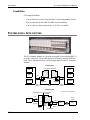
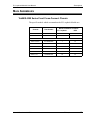
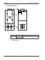
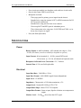
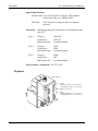
® CONNECTING THE FUTURE ® E1 LOOPBACK MODULE USER MANUAL 116758 Issue A Rev 1 E1 Loopback Module User Manual Document Number 116758 Issue A Rev 1 Copyright© Telect, Inc., 1999, All Rights Reserved. The following are trademarks and registered trademarks of Telect, Inc., 2111 N. Molter Rd., Liberty Lake, Washington 99019: TeleMIX™ , Telect , and Connecting the Future . FCC Compliance This device complies with Part 15 of the FCC rules. Operation is subject to the following conditions: 1) This device may not cause harmful interference, and 2) This device must accept any interference received, including interference that may cause undesired operation. Agency approval, for U.S. or Canada, is labeled on the side of the module. Warranty Telect warrants to Buyer that the E1 Loopback Module is free from defects in material and workmanship under normal use and service, subject to exceptions stated herein. The purchased module is warranted for a lifetime period of five years from the date of shipment to the original Buyer. The exception will be with those products Telect subcontracts and resells to original customers; these will carry the manufacturer’s warranty or Telect’s warranty, whichever is greater, from the date of shipment to the original Buyer. If any module purchased from Telect is defective, or does not conform to the contract for sale, Buyer must so notify Telect promptly after receipt of the module and Telect, or its authorized or designated representative, shall have the right to inspect the goods on Buyer’s premises. If Telect determines the product was defective at the time of delivery, at Telect’s direction, Buyer may either return the product with shipping charges prepaid to Telect and obtain a refund of the purchase price or return the defective product to Telect for repair or replacement. Claims for nonconforming orders will not be considered unless made in writing to Telect within ten days after Buyer’s receipt of the product. Since Telect’s responsibility ceases upon delivery of the product in good order to a carrier, any claims for damage or shortage in transit must be brought against the carrier. Limitations of Warranty CORRECTION OF DEFECTS BY REPAIR OR REPLACEMENT OR REFUND OF PURCHASE PRICE TO BUYER SHALL CONSTITUTE FULFILLMENT OF ALL OBLIGATIONS TO BUYER. TELECT WILL NOT BE LIABLE FOR ANY CONSEQUENTIAL DAMAGES OR PERSONAL INJURY OR FOR LOSSES, DAMAGES, OR EXPENSES DIRECTLY OR INDIRECTLY RESULTING FROM THE USE OF ITS PRODUCTS. Telect assumes no warranty liability with respect to defects in its product caused by: a) Buyer’s modification of the product b) Buyer’s attempt to repair the product c) Buyer’s negligent, accidental, or other improper use of the product. d) Buyer’s installation, or maintenance of the product other than in the manner describe herein. Telect does not assume any warranty liability for any items purchased by Buyer either for drop shipment to Telect for factory installation and wiring, or for installation and wiring by Buyer at his facility. Any repairs made by Telect after the warranty period are warranted for ninety (90) days from the date of repair or date of return shipment to Buyer, whichever is applicable. THE ABOVE WARRANTY SUPERSEDES AND IS IN LIEU OF ALL OTHER WARRANTIES, EXPRESSED OR IMPLIED, AND ALL OTHER OBLIGATIONS OR LIABILITIES OF TELECT, INCLUDING ANY WARRANTIES OF MERCHANTABILITY AND FITNESS FOR A PARTICULAR PURPOSE. No agent, distributor, or other party is authorized to make any warranties on behalf of Telect or to assume for Telect any other liability in connection with any of Telect’s products. ii Telect, Inc. 116758 Issue A Rev 1 Contents 1 Descriptions E1 Loopback Module................................................................... 1-1 Capabilities ............................................................................ 1-2 System-Level Applications.......................................................... 1-2 Main Assemblies.......................................................................... 1-3 TeleMIX 4000 Series Front Cross-Connect Chassis ............. 1-3 E1 Loopback Module............................................................. 1-4 Specifications............................................................................... 1-5 Power ..................................................................................... 1-5 Electrical Functional .............................................................. 1-5 Physical .................................................................................. 1-6 Environmental........................................................................ 1-7 2 Installation Installation Considerations .......................................................... 2-1 Location and Space ................................................................ 2-1 Tools and Equipment ............................................................. 2-1 Inspection..................................................................................... 2-1 Installation Procedure .................................................................. 2-2 Rack Mount............................................................................ 2-2 Wall Mount ............................................................................ 2-2 Power Connection.................................................................. 2-3 3 Electrical Operation Block Diagram ............................................................................. 3-1 Power ........................................................................................... 3-2 Data Signals ................................................................................. 3-2 DSX-1 .................................................................................... 3-2 Issue A Rev 1 116758 Telect, Inc. iii Loopback Mode ..................................................................... 3-3 Power, Signal Loss ................................................................ 3-3 4 Service Owner Maintenance ..................................................................... 4-1 Troubleshooting ........................................................................... 4-1 In-Warranty Service ..................................................................... 4-2 Out-Of-Warranty Service............................................................. 4-3 Repacking For Shipment ............................................................. 4-3 iv Telect, Inc. 116758 Issue A Rev 1 1 Descriptions E1 LOOPBACK MODULE Telect’s E1 Loopback Module terminates an E1 (2.048 Mbs) line within a DSX-1, and, through the use of loop-up and loop-down codes, it allows a technician to perform line loopback from a remote location. This module is used exclusively with Telect’s TeleMIX™ 4000 Series Front Cross-Connect chassis. The specific chassis models which accommodate the E1 Loopback Module are noted in the subsection, “Main Assemblies.” The module occupies two chassis slots. Issue A Rev 1 116758 Telect, Inc. 1-1 Descriptions E1 Loopback Module User Manual Capabilities E1 Loopback Modules: • • • Can perform cross-connect and loopback on four independent circuits. May be intermixed with other TeleMIX network modules. Can be used as a demarcation point, if –48 Vdc is available. SYSTEM-LEVEL APPLICATIONS The E1 Loopback Module may be used at an equal level test point (DSX-1) on an E1 carrier line. The module performs all normal, manual DSX functions. These illustrations show common applications for the E1 Loopback Module. Central Office E1 Loopback Modules OTR HDSL DS1 O I OTR M O I M O I HDSL O I O I O I D4 BANK D4 BANK Loopback Loopback 199.6m (655 ft) DSX-1 26m (85 ft) DSX-1 199.6m (655 ft) Customer Site Demarcation Point M O O I I O 199.6m (655 ft) I DS1 CPE DSX-1 1-2 Telect, Inc. 655’/85’ = MAX. DISTANCES E1 Loopback Module M O I Central Office DS1 26m (85 ft) O I O I FOT 199.6m (655 ft) FOT Facility Loopback 116758 Issue A Rev 1 E1 Loopback Module User Manual Descriptions MAIN ASSEMBLIES TeleMIX 4000 Series Front Cross-Connect Chassis The specific models which accommodate the E1 Loopback Module are: Chassis Part Number Maximum Module Positions E1 Loopback DSX Wall-Mount 010-0000-4022 2 4 Wall-Mount 010-0000-4020 4 9 19"W x 5.25"H 010-0000-4006 7 14 19"W x 7"H 010-0000-4016 7 14 19"W x 5.25"H 010-0000-4000 8 16 19"W x 7"H 010-0000-4010 8 16 23"W x 5.25"H 010-0000-4001 10 21 23"W x 7"H 010-0000-4011 10 21 Rack-Mount Issue A Rev 1 116758 Telect, Inc. 1-3 Descriptions E1 Loopback Module User Manual E1 Loopback Module Lock Tab Status LED 1 3 STATUS M M O O I I 2 Patch Ports Pogo Pins 4 %< STATUS M M O O I I T T OUT R R T T IN R R 1 2 3 T Front CrossConnects OUT R I/O Connects T IN R 4 4 DSX Side 3 2 1 Network Side, Model Part Number 710-4004-E1-X Commercial 710-4004-E1RJ-X Description “X” = -1, -2, or -3—represents the type of in-band code (factory programmed) Module Features 1-4 Telect, Inc. 116758 Issue A Rev 1 E1 Loopback Module User Manual • • • • Descriptions Four circuits per module (two daughter cards with two circuits each) One tri-color status LED for each circuit Backplane card with: ◊ Three pogo pins for primary power input from the chassis ◊ Standard wire-wrap pins (square 0.045") or RJ48 connectors for IN/ OUT network connections ◊ Standard wire-wrap pins for front cross-connects ◊ Wire-wrap BATT and RTN pins for redundant power ◊ Three alarm-status wire-wrap pins—LOS, PWR and COM—to indicate loss of power or signal Fuse (not field replaceable) SPECIFICATIONS Power Battery Inputs: A and B redundant, –48V nominal, the range is –42 to –56 Vdc (this battery must be available for loopback to operate) Input Current: 80 mA nominal @ –48 Vdc, normal DSX mode 120 mA max. @ –56 Vdc, all channels in loopback mode Backplane On-Board Power Conversion: +5V, ≤600 mA Internal Fuse: 0.25A; not field replaceable Electrical Input Data Rate: 2.048 Mb/s ± 50 b/s Input Data Format: AMI, HDB3 (signal format independent) Input Level: ±2 dB DSX Impedance: Characteristic of 120-ohm termination, ±5% Output Level: Nominal E1 DSX per ITU G.703 Output Pulse Shape: Meets ITU G.703 template Output Data Format: Same as input, bipolar violations are transparent to output Monitor Level: –20 dBDSX down from the OUT signal Issue A Rev 1 116758 Telect, Inc. 1-5 Descriptions E1 Loopback Module User Manual Input/Output Distance Network Side: Up to 199.6m (655 ft.) using 22 AWG shielded twisted pair cable (e.g., ABAM or PIC) DSX Side: Up to 26m (85 ft.) using 24 AWG 5-conductor pair wire Loop Code: In-band code detection in presence of a maximum bit error rate of 10-3 Type 1 Loop Up Loop Down Detection Period 11001100 11101110 5 seconds nominal Type 2 Loop Up Loop Down Detection Period 11000 11100 5 seconds nominal Type 3 Loop Up Loop Down Detection Period 11000 1110 5 seconds nominal Jitter Tolerance, Attenuation: Per ITU G.823 Physical Plastic Housing D H H Height Including Lock Tab: 11.7 cm (4.63 in.) Excluding Lock Tab: 11.1 cm (4.38 in.) W Width: 5.1 cm (2.0 in.) D Depth Including Rear Pins: 11.1 cm (4.38 in.) Excluding Rear Pins: 9.5 cm (3.75 in.) W 1-6 Telect, Inc. 116758 Issue A Rev 1 E1 Loopback Module User Manual Descriptions Environmental Operating Temperature: 0°C to 40°C (32°F to 104°F) Storage Temperature: –40°C to 65°C (–40°F to 149°F) Operating and Storage Humidity: 10% to 95%, noncondensing Issue A Rev 1 116758 Telect, Inc. 1-7 2 Installation INSTALLATION CONSIDERATIONS Location and Space The E1 Loopback Module occupies two module slots within a Telect TeleMIX 4000 Series chassis. (See Section 1, “Main Assemblies,” for a list of the specific chassis.) Tools and Equipment No special tools or equipment are required. Telect recommends 22 AWG wire for all wire-wrap connections. INSPECTION Compare the contents of the E1 Loopback Module shipping container with the packing list. Call Telect if you are missing anything. NOTE Telect is not liable for shipping damage. If the shipping container is damaged, keep it for the carrier’s inspection. Notify the carrier and call Telect’s Customer Service Department: 1-800-551-4567 or 1-509-926-6000 Keep the container until you have checked equipment operation. If you experience any kind of problem, call Telect’s Customer Service Department. Use the original, undamaged container if you are instructed to return the E1 Loopback Module to Telect. Issue A Rev 1 116758 Telect, Inc. 2-1 Installation E1 Loopback Module User Manual INSTALLATION PROCEDURE CAUTION The E1 Loopback Module is sensitive to electrostatic discharge. Follow ESD procedures. Rack Mount Step Action 1. Before inserting the E1 Loopback Module in the chassis, test the pogo pins by pressing each one. Pins should easily compress and re-extend. Primary power feed problems could result if they do not. 2. Align the module’s bottom guide rails with the slots in the bottom of the TeleMIX chassis. 3. Pivot the module upright. When the module is fully inserted, the top lock tab will engage and hold the module securely in position. 4. Make network IN/OUT and alarm-status connections at the rear of the module. For wire-wrap, Telect recommends 22 AWG wire. 5. Identify circuits on the circuit designation strip on the front of the chassis. Wall Mount 2-2 Step Action 1. Pull all network IN/OUT, alarm status, and redundant power wiring through the TeleMIX chassis’ side opening. Telect recommends 22 AWG for wire-wrap connections. 2. Make network IN/OUT and alarm-status connections at the rear of the module, before inserting the module into the chassis. (See the following subsection on power connection installation.) Telect, Inc. 116758 Issue A Rev 1 E1 Loopback Module User Manual Installation 3. Load modules in the chassis from left to right, or choose any available slot. Taking care with the attached wires, align the module’s bottom guide rails with the slots in the bottom of the chassis. 4. Pivot the module upright and push gently. When the module is fully inserted, the top lock tab will engage and hold the module securely in position. Power Connection The E1 Loopback Module receives primary power when the module’s pogo pins contact the power PCB inside the TeleMIX chassis. This office battery power should be fused or breakered at a power distribution panel mounted in the bay. You can connect a redundant power source to the module. Attach 20–22 AWG wire between the source and the BATT and RTN pins, located on the rear of the module. Ground The TeleMIX chassis should be grounded at the equipment rack. The E1 Loopback module provides an internal signal ground at the middle pogo pin. Issue A Rev 1 116758 Telect, Inc. 2-3 3 Electrical Operation BLOCK DIAGRAM D S X LIU LIU T R OUT T IN R Alarm Relays Detect and Control LIU T R OUT T IN R +5V Gnd LIU Daughter Card LIU = Line Interface Unit CPE = Customer Premise Equipment CPE (1 Set of 4) Power Conv. T Out R In T R SEE RJ48 LOS, PWR, COM ~ D S X Network I/O Network I/O SEE RJ48 C.GND (Not Used) BATT. RTN BATT. RTN S.GND Pogo Pins Backplane Pogo Pins Cross-Connect Paths 4 per channel, 8 per board, 16 per module, connect to corresponding network I/O lines. RJ48 Modular Jack 1 8 PIN 1 2 3 4 5 6 7 8 FUNCTION Receive, Ring Receive, Tip Not Used Transmit, Ring Transmit, Tip Not Used Not Used Not Used CIRCUIT R IN T R OUT T RTN S.GND BATT. (REAR OF MODULE) Issue A Rev 1 116758 Telect, Inc. 3-1 Electrical Operation E1 Loopback Module User Manual POWER The purpose of the power supply is to light the module LEDs, which show module status, and to enable the loopback test functions. The status LEDs on the front of the module light green when: • • Power is present, and Signal is present from both the network and the CPE side Primary power, from the TeleMIX chassis’ internal power PCB, enters the E1 Loopback Module through its three pogo pins. The outside pogo pins connect to the power circuit; the middle pin connects to shield ground (protection for the Bantam jacks). The backplane inside the module housing has an on-board power converter component that produces +5V from the –48V supply. A redundant power supply, when connected at the rear of the module, backs up power that fails at the primary source. If the module’s backplane power-converter fuse blows, the redundant power source cannot help. NOTE You cannot replace this fuse on-site. DATA SIGNALS The E1 Loopback Module provides full DSX functionality for four DSX-1 circuits. The module also provides the ability to perform remote loopback operations on those circuits. DSX-1 The status LED lit green indicates normal DSX operating mode (no loopback). The analog E1 signal coming from the network OUT connection is routed to the first LIU analog receive path. The LIU converts the signal to digital and sends it to the second LIU (digital receive input). The second LIU regenerates the signal, converting it back to analog, and sends it on the transmit line to the DSX portion of the circuit. The signal appears at the crossconnect pins for customer equipment access and at the jacks. The signal coming from the customer is handled the same way, being regenerated and transmitted to the network. 3-2 Telect, Inc. 116758 Issue A Rev 1 E1 Loopback Module User Manual Electrical Operation Bantam Jack Interface Each channel has three Bantam jacks: MON Nonintrusive monitor of the network equipment output. The signal level at the MON jack is 20 dB below the OUT jack signal. OUT An intrusive jack used to break the cross-connect and access the output from the network equipment. IN An intrusive jack used to break the cross-connect and access the input to the network equipment. A standard Bantam jack plug accesses the OUT and IN E1 signal for patching. MON can be used for patching or testing. Loopback Mode The module monitors the network OUT signal for loop codes: Type 1 Loop Up Loop Down 11001100 11101110 Type 2 Loop Up Loop Down 11000 11100 Type 3 Loop Up Loop Down 11000 1110 After receiving the loop-up code for five seconds, the Network signal is looped back to the Network. The Customer signal coming into the module is terminated and an alarm indication signal (AIS) is sent to the customer. The status LED turns amber, indicating the loopback condition. After receiving the loop-down code for five seconds, loopback is cancelled, and the LED turns green. Power, Signal Loss Loss of Power Power failure, at the external power source or from the backplane powerconverter fuse blowing, causes the bypass relays to de-energize. Data in both directions take a 2 ms “hit.” The relays restore the signal paths around the LIUs. Any channel in loopback mode at the moment of power loss loops down to normal DSX operation. The power-fail alarm contacts close, sending an alarm back to the network. All the module LEDs switch off. Issue A Rev 1 116758 Telect, Inc. 3-3 Electrical Operation E1 Loopback Module User Manual Loss of Signal If no network or customer signal is detected—the signal passes 175 consecutive zeros or signal amplitude drops below 0.3V—the “loss of signal” (LOS) alarm contacts close, sending an AIS to the signal source (network or customer).The status LED for the affected circuit lights red according to the condition listed in the table in the next subsection. Status and Alarms LED Color 3-4 Telect, Inc. Condition Green Normal DSX mode Amber Network loopback mode Solid Red Loss of signal, network side Slow Blinking Red Loss of signal, customer side Fast Blinking Red Loss of signal, both network and customer side Off Power failure or internal fuse blown 116758 Issue A Rev 1 4 Service OWNER MAINTENANCE Telect’s E1 Loopback Module does not need preventive maintenance. Should the module fail, you must return it to Telect for repair or replacement, according to the limits of the warranty. If problems occur after installation, check all cable connections and the installation instructions in Section 2. If a problem persists, refer to the next subsection, “Troubleshooting,” or contact your Telect Customer Service Representative. TROUBLESHOOTING Use this LED status table in conjunction with the troubleshooting table that follows on the next page: LED Color Issue A Rev 1 116758 Condition Green Normal DSX mode Amber Network loopback mode Solid Red Loss of signal, network side Slow Blinking Red Loss of signal, customer side Fast Blinking Red Loss of signal, both network and customer side Off Power failure or internal fuse blown Telect, Inc. 4-1 Service E1 Loopback Module User Manual Problem Symptoms LEDs fail to light upon module installation. Troubleshooting Measures Possible power supply problem. Verify: • Chassis is receiving power. • Pogo pins are working properly. • Module is correctly seated in chassis. If the problem persists, replace the module. “Power Failure” alarm; LEDs of all modules are off. Power source failure. Loopback function should resume once power is restored. All four LEDs are off, but adjacent modules are operating. The fuse in the backplane power converter has probably blown. Replace the module. The LEDs for circuits 1 and 2 or circuits 3 and 4 are off. A fuse on the daughter board for the affected circuits has probably blown. Replace module. “Loss of Signal” alarm; LED for the affected circuit is red (see LED table). Troubleshoot signal for each affected circuit according to accepted local practices. If you isolate the fault to the module, replace it. Circuit fails to respond to either loop signal—LEDs remain green (normal DSX) or LEDs remain amber (loop-up mode). Verify the correct code is being transmitted on Network OUT of the E1 line. (See Section 1, “Specifications,” for signal format.) If correct code is being sent, replace the module. Unable to monitor or patch. Try a different monitor or patch cord. If the problem persists, replace the module. IN-WARRANTY SERVICE Contact your Telect equipment distributor, or call a Telect Customer Service Representative: 1-800-551-4567 1-509-926-6000 (Customers outside the USA, use the 1-509 number.) Telect will repair or replace defective products within the limits of the warranty. See “Repacking for Shipment” in this section. NOTE Call a Customer Service Representative for a Return Material Authorization (RMA) before returning any equipment. 4-2 Telect, Inc. 116758 Issue A Rev 1 E1 Loopback Module User Manual Service OUT-OF-WARRANTY SERVICE The procedure for out-of-warranty service is the same as for in-warranty service, except that Telect charges a processing fee, and you must submit a Purchase Order along with a Return Material Authorization (RMA) before returning equipment. Call a Customer Service Representative for help getting these forms. The processing fee guarantees a repair estimate and is credited against actual material and labor costs. REPACKING FOR SHIPMENT Step Action 1. Tag the equipment showing owner’s name, address, and telephone number, together with a detailed description of the problem. 2. Use the original shipping container if possible. If you do not have it, package the equipment in a way to prevent shipping damage. Include the RMA inside the container. 3. Insure the package. NOTE Telect is not liable for shipping damage. Issue A Rev 1 116758 Telect, Inc. 4-3 Telect, Inc. 2111 N. Molter Rd. P.O. Box 665, Liberty Lake, WA 99019 509-926-6000, 800-551-4567, Fax 509-926-8915 E-mail: [email protected] Internet: http://www.telect.com