1
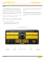
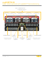
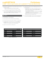
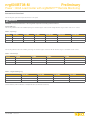
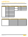
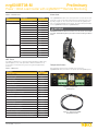
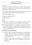
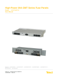
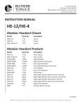
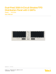
nrg600BT08-M
Power :: 600A Load Center with nrgSMART™ Remote Monitoring
Installation Guide
nrgSMART describes the family of distributed network monitoring and
management products, from BDFB’s, high current and low current
secondary panels, as well as Web interface software and data server
solutions. nrgSMART allows you to collect performance data on distributed assets and tools to help you efficiently access business critical and
actionable information.
• Collect feed voltage, circuit current, and temperature
• Network Data Collection: Intelligent interpretation of the collected
data, based on equipment data signature (smart alarms), drives
relevant business decisions.
- Hosted Data Services available through the nrgSMART-ADH
service
- SNMP Interface comes standard when used with the
nrgCONTROL-BT
Telect recognizes the industry need to manage distributed assets more
efficiently, get better power performance out of deployed assets, as well
as pursue realistic and achievable alternative energy goals. Through
nrgSMART, access to data at the equipment level provides the foundation
for managing performance of a distributed DC power distribution system.
• Data Analytics: When used in conjunction with the nrgCONTROL-BT
and nrgSMART-ADH Service, the nrg600BT08-M can be remotely
monitored through the nrgSMART web portal and dashboard views.
Remotely access the data that is important to you. Instantly see realtime results at any of your distributed sites.
• Individual circuit monitoring: measure power at the circuit level.
This enables powerful trend analysis and insights into equipment
performance and enables preventative maintenance processes.
- High accuracy, 100% passive monitoring, modular sensor
modules
© Telect, Inc., All Rights Reserved, 145121-1 A0
1.509.926.6000 :: telect.com
1
nrg600BT08-M
Preliminary
Power :: 600A Load Center with nrgSMART™ Remote Monitoring
Overview
The bullet terminals can accept either TFD fuse holders or bullet terminal
breakers. Single pole, double pole, and triple pole breakers are also
supported.
Telect’s nrg600BT08-M 600A dual-feed 8/8 circuit breaker/TFD Load
Center with 5 GMTs features -48V operating voltage to fit in legacy and
“next-gen” network applications, with advanced circuit level monitoring
features engineered into a 4RU footprint. Each of the dual feeds contains
eight positions for either bullet-style breakers or TFD fuse holders. Each
of the dual feeds also includes five GMT fuses, providing ample capacity
for distribution to a broad range of components.
The GMT fuse holders are mounted inverted so that the GMT indicator
flag flips downward when tripped, making identification and detection
easier, especially on taller racks. In addition, the GMT fuse holders/
sensors are generously spaced for easy grip of fuses and better heat
dissipation.
The panel provides total front access to fuses and LED status. Below the
status LED console is a pull-out designation card holder.
All terminals for inputs, outputs, ground, and alarms are on the rear of the
panel. All terminals are covered by a single full-width transparent terminal
cover:
• Inputs are studs for dual-hole lugs.
• Ground terminals are dual, threaded holes for gound bolts.
• Output studs for dual-hole lugs and screw posts for GMTs.
• Power/fuse alarm terminals are wire wrap pins.
Figure 1 – nrg600BT08-M Front View
A Feed Bullet
Terminal Sensors
A Feed GMT
Sensors
© Telect, Inc., All Rights Reserved, 145121-1 A0
1.509.926.6000 :: telect.com
Alarm Card
Designation Card
2
B Feed GMT
Sensors
B Feed Bullet
Terminal Sensors
nrg600BT08-M
Power :: 600A Load Center with nrgSMART™ Remote Monitoring
Figure 2 – nrg600BT08-M Rear View
Grounding 1/4 bolts on 5/8" centers
(on each side of chassis)
B Feed Inputs
B Feed Returns
3/8 studs on 1" centers 3/8 studs on 1" centers
B Feed Bullet Load Terminal
1/4 studs on 5/8" centers
B Feed GMT Load
Terminal
#6 Single Screw
B Feed Bullet Return Terminal
1/4 studs on 5/8” centers
© Telect, Inc., All Rights Reserved, 145121-1 A0
1.509.926.6000 :: telect.com
PWR and FUSE Dry Contact
Alarm Terminations
Temperature
Probe Input
B Feed GMT Return
Terminal
#6 Single Screw
Temperature
Probe Input
Removable screwdown terminal block
for nrgNET
3
A Feed Inputs
3/8 studs on 1" centers
A Feed Returns
3/8 studs on 1" centers
A Feed GMT Load
Terminal
#6 Single Screw
A Feed GMT Return
Terminal
#6 Single Screw
A Feed Bullet Load Terminal
1/4 studs on 5/8” centers
A Feed Bullet Return Terminal
1/4 studs on 5/8” centers
nrg600BT08-M
Preliminary
Power :: 600A Load Center with nrgSMART™ Remote Monitoring
Specifications
Inputs
Voltage range, nominal voltage
Grounding
-40V to -60V (Nominal -48Vdc)
Earth GND terminal bolts
(with washers) for dual-hole
compression lug
• Two pair of 1/4 - 20 threaded holes
on 5/8 in. centers.
• Torque bolts (using 7/16 in. or 12 mm
wrench) to 50 in.-lb (5.5 N•m), max.
#2 AWG recommended
Max input load rating
600A per side at max
Short circuit withstand rating
5000A (breakers/fuses); 450A GMT
Nominal power loss at full load
Less than 75W per side @ 28,000W
full load per side (600A x 48V)
Ground wire size
Percentage of full power
dissipation at nominal voltage
Less than 1%
Voltage Sensor
Max. input interrupt device
750A
Input Terminal Studs
(with nuts, flat washers, and
spring washers) for dual-hole
compression lugs
• Two pair of 3/8 – 16 studs on 1 in.
centers per terminal [max. lug width
of 1.94 in. (49.2 mm)] per pair
• Torque nut (using 9/16 in. or 15 mm
wrench) to 150 in.-lb (~17 N•m),
max.
Input wire size
#1 AWG to 750 MCM
0 to -19.99V: ±0.3V
-20V to -60V: ±0.1V
Voltage Measurement Range
0 to -60VDC
Feed Voltage Detection
0 to -19.99V: Alarm
-20V to -60V: Normal
NOTE:
• Voltage measurement may be slightly different than at input
terminal blocks due to the voltage drop within the panel.
• Sensors are factory calibrated and do not require user adjustment.
Dual-Hole Outputs
Communication
Max. output single-pole, longdelay circuit breaker (ea.)
100A
Max. output TPS or TLS
125A
Max. output load (ea.) continuous
100A
Minimum short circuit interrupt
rating
5000A
Output terminal studs (with
KEPS, nuts, and washers) for
dual-hole compression lugs
• 1/4 - 20 studs on 5/8 in. centers
[max. lug width of 0.680 in. (15.8
mm) for a BATT terminal and
0.70 in. (17.7 mm) for a RETURN
terminal].
• Torque bolts (using 7/16 in. or 12
mm wrench) to 50 in.-lb (~5.5
N•m), max.
Output wire size
Sensor Accuracy
nrgNET sensor and alarm
card power
-48VDC nominal
nrgNET data communication
RS-485
nrgNET connector
Removable 5-pin connector with screw
down terminals
nrgNET connector functions
nrgNET IN from the nrgCONTROL or
nrgSMART Panel, nrgNET OUT to next
inline nrgSMART panel
Supported protocols
Proprietary nrgNET used to communicate between panels and controller
Fit and Finish
#14 AWG minimum
Material
14-gauge steel
Color
Pewter grey powder coat
Mechanical
GMT Outputs
20A
Dimensions (L x W x H):
12” x 17.25” x 7”
Max. GMT output load (ea.) continuous
14A
Rack space
4RU
Minimum short circuit interrupt
rating
450A
Environmental
GMT output terminals for
compression lugs
• 10, removable, #6-32 panhead
screws (max. lug width of 0.29 in.
[7.4 mm]).
• Torque to 6.3 in.lb (~0.7N•m), max.
Max. GMT output fuse (ea.)
GMT output wire size
Operating temperature
-5° to +44°C
Humidity
0 to 90%, non-condensing
Weight (approximate)
#22 AWG to #12 AWG, depending on
output fuse rating
Dry Contact Alarms
Installed
47 lb (21.3kg)
Shipping
49.1lb (22.3kg)
Compliance
Alarm wire size
#22 to #18 AWG
Alarm terminals
Wirewrap
Relay contact ratings
Dry Form-C contacts (1A @ 30 VDC,
0.5A @ 60 VDC, 0.3A @ 125 VAC)
Max. Alarm Power Rating
@24V: 72 mA (1.73W)
@48V: 147 mA (7.06W)
© Telect, Inc., All Rights Reserved, 145121-1 A0
1.509.926.6000 :: telect.com
UL, NEBS level 3
Warranty:
• Standard 1 year warranty on all parts.
• The warranty is extended through the addition of the annual
maintenance and support contract (nrgSMART- APSC).
4
nrg600BT08-M
Power :: 600A Load Center with nrgSMART™ Remote Monitoring
Important Installation Guidelines:
Installation
! ALERT
• Elevated Operating Ambient Temperature :: If you install the rack
in a closed or multi-unit rack assembly, the operating ambient temperature of the rack environment may be greater than room ambient.
Therefore, take care to install the equipment in an environment
compatible with the maximum operating temperature.
• Reduced Air Flow :: Installation of the equipment in a rack should
be such that the amount of air flow required for safe operation of the
equipment is not compromised.
• Mechanical Loading :: Mounting of the equipment in the rack
should be such that a hazardous condition is not achieved due to
uneven mechanical loading.
• Circuit Overloading - Give consideration to the connection of the
equipment to the supply circuit and the effect that overloading of the
circuits might have on overcurrent protection and supply wiring. Use
appropriate consideration for equipment nameplate ratings when
addressing this concern.
• Reliable Earthing :: Maintain reliable earthing of rack-mounted
equipment. Pay particular attention to supply connections other than
direct connections to the branch circuit (e.g., use of power strips).
• Disconnect Device :: Incorporate a readily accessible disconnect
device in the building installation wiring.
ALERT! It is recommended that this product is installed within a restricted
access location where access is through the use of a tool, lock and key, or
other means of security, and is controlled by the authority responsible for
the location. This product must be installed and maintained only by
qualified technicians.
Verify all connections meet requirements specified in local electric codes
or operating company guidelines before supplying power. Unit shall be
protected by a listed circuit breaker or branch-rated fuse sufficient to
interrupt power levels specified on the preceding page.
Rack Mounting
• The nrg600BT08-M panel can be mounted in 19-in. & 23-in. EIA and
WECO racks.
• The nrg600BT08-M panel can be flush-mounted, 2-in extended, or
4-in extended.
1. Use the 12 screws provided to fasten the brackets to the panel.
2. Locate an unused rack position and mount panel using at least four
sets of fasteners (screws, flat washers, and star washers provided) per
side. It’s best to mount the panel as high as possible on the rack.
Inspection
Please read and understand all instructions before starting installation. If
you have questions, contact Telect Technical Support at support@telect.
com or call 1.509.926.6000.
3. Tighten screws to 35 in.-lb (4.29 N•m). Telect recommends using a
seismic rack for best rigidity. Also, if you intend on installing more
than one panel per rack, you need to plan a rack arrangement that
dissipates heat efficiently.
When you receive the equipment, carefully unpack it and compare it to
the packaging list. Please report any defective or missing parts to Telect
Quality at [email protected] or call 1.509.926.6000.
4. Loosen (you need not remove) four screws securing transparent
terminal cover to the rear of the panel.
5. Remove the cover.
Telect is not liable for transit damaged. If the product is damaged, please
report it to the carrier and contact Telect Quality.
NOTE: The nrg600BT08-M is suitable for installation as part of
a Common Bonding Network (CBN) for installation in Network
Telecommunication Facilities an OSP.
© Telect, Inc., All Rights Reserved, 145121-1 A0
1.509.926.6000 :: telect.com
5
nrg600BT08-M
Preliminary
Power :: 600A Load Center with nrgSMART™ Remote Monitoring
Table 1 - Temperature Rating
! WARNING
WARNING! Failure to properly ground this equipment can create
hazardous conditions for installation personnel and for the equipment.
! ALERT
ALERT! Only use components and crimping tools approved by agencies
or certifying bodies recognized in your country or region, such as
Underwriter’s Laboratories (UL), TUV, etc.
6.
Use a listed (approved) crimping tool to attach a listed (approved),
dual-hole compression lug for 1/4-20 studs on 5/8-in. centers onto #2
AWG ground wire.
7.
If desired (highly recommended), lightly coat anti-oxidant on lug,
grounding terminal, and surrounding contacting surface.
8.
Connect the lug using the 1/4 -20 bolts, lock washers, and flat
washers provided.
9.
Tighten bolts to ~50 in.-lb (~5.6 N•m), max.
Max. Current
Rating Per Side:
Min. Cable Insulation
Temperature Rating:
-5° to 49°C
(23° to 120°F)
600A
75°C (167°F)
49° to 55°C
(120°F to 131°F)
550A
75°C (167°F)
49° to 55°C
(120°F to 131°F)
600A
90°C (194°F)
12. Insulate lug barrels with UL94 V-0-rated heat-shrink tubing.
13. Clean terminals and lugs with nonabrasive, nonmetallic pad.
14. If required, lightly coat anti-oxidant on lugs and input BATT and RETURN terminals, and then connect the lugs to input terminals on the
back of the panel.
15. Tighten lugs to 150 in.-lb (~17 N•m), max.
16. Make sure all interrupter positions are either empty, off, or contain
dummy fuses (phoney, inoperative all-plastic slugs).
10. Make sure the power is off (open breaker, dummy fuse, or open fuse
holder at primary power distribution unit or battery) before connecting
this panel’s input cables to a PDU or battery.
! ALERT
! WARNING
ALERT! Only qualified service personnel should replace fuses. The
installer must verify that a readily accessible protection device is
incorporated in the building wiring feeding the panel: 750A (max.)
protection device for a 600A panel.
WARNING! Before connecting input power cables, make sure the
input power to the panel is turned off.
11. For input wiring - wiring used as inputs to this load center:
• Crimp dual-hole compression lugs onto #1 AWG to 750MCM copper
wires. The choice of input wiring depends on the following criteria:
• Input interrupt device rating affects the size of input wiring.
• Ambient operating temperature affects the type of input wire
insulation. Use Table 1 to choose the correct temperaturerated input wires. For further information consult the National
Electrical Code (NEC).
© Telect, Inc., All Rights Reserved, 145121-1 A0
1.509.926.6000 :: telect.com
Ambient Operating
Temperature Range:
6
nrg600BT08-M
Power :: 600A Load Center with nrgSMART™ Remote Monitoring
Power A
nrgNET Connection to the
nrgCONTROL-BT
Fuse Alarm A
Fuse Alarm B
Power B
Figure 3 – nrg600BT08-M Alarm Card
LED State
PWR A/B
FUSE Alarm A/B
nrgNET Connection
Green
Operating normally
Operating normally
Active communication to nrgCONTROL-BT
Blinking Green
PWR B, boot loader loading
N/A
Used for visual identification through controller command
Yellow
PWR A, boot loader mode
N/A
N/A
RED
PWR A or PWR B feed
voltage alarm < -20VDC
A feed or B feed fuse alarm
Connected to nrgCONTROL, but no communication to this
specific panel within last 3 seconds
RED Single Blink
N/A
N/A
Defective panel. Contact Telect for replacement.
RED Double Blink
N/A
N/A
Invalid communication to nrgCONTROL. Check that COM+
and COM- did not get swapped.
No Light
No power to feed
No alarm
No power present on nrgNET IN connector
Boot Loader Mode
The nrg600BT08-M alarm card will receive remote firmware updates automatically from the nrgCONTROL-BT. The boot loader mode is indicated by a
yellow PWR A LED. In this mode, the power and fuse LEDs are used for diagnostics and do not represent the power and fuse status. A blinking green
PWR B LED in conjunction with the yellow PWR A LED indicates the firmware is actively being updated. The update process lasts approximately
7 seconds.
NOTE: The following steps require that the nrg600BT08-M is connected to an nrgCONTROL-BT controller. The nrgCONTROL-BT provides power to the
nrg600BT08-M’s alarm card, which is required for steps 17-19 and steps 22-27. Reference the nrgNET connectivity section for further details.
17. Enable protection device (fuse or breaker) at primary PDU to turn on Feed A to Side A of panel and then check voltage and polarity at input
connectors of panel. Also, check that
• PWR A LED on front of panel turns on (green).
• PWR B LED is off
18. With PWR A LED green (normal operation) — but with PWR B LED off — test power-fail relay and contacts at PWR alarm terminals on rear of panel:
• Expect open circuit (∞Ω) between Terminals C and NC.
• Expect an continuity (0Ω) between Terminals C and NO.
19. Also, test fuse alarm relay contacts at fuse (CB/Fuse Alarm) terminals on the rear of the panel.
• Expect continuity (0Ω) between Terminals C and NC.
• Expect an open circuit (∞Ω) between Terminals C and NO.
20. Repeat Steps 17 through 19 to power up Side B. PWR A and PWR B LEDs must both be green.
© Telect, Inc., All Rights Reserved, 145121-1 A0
1.509.926.6000 :: telect.com
7
nrg600BT08-M
Preliminary
Power :: 600A Load Center with nrgSMART™ Remote Monitoring
27. For GMT output wiring, use #22 to #12 AWG copper wire and
proceed as follows:
a. Working with one wire at a time, at the panel end of the wire,
crimp a single-hole ring or fork lug, as required by NEC.
b. Clean the panel terminals and lug (if applicable) with a nonabrasive, nonmetallic cleaning pad.
c. If required, lightly coat anti-oxidant on lug/wire and output BATT
and RETURN terminals, and then connect to terminals. (NEC
specifies only one load at each output terminal.)
d.Tighten panhead screws to no greater than 6.3 in.-lb (~0.7 N•m).
e. Connect other end of output wire to load.
21. With PWR A and PWR B lit green, test power-fail relay and contacts at
PWR alarm terminal:
• Expect continuity (0Ω) between Terminals C and NC.
• Expect an open circuit (∞Ω) between Terminals C and NO.
22. For circuit breaker or TPS/TLS output wiring, crimp dual-hole lugs
onto one end of #6 to #2 AWG copper output wires for single-pole
outputs or #6 to 2/0 AWG for double-pole circuit breaker outputs, as
required by NEC. (Work with one output wire at a time.)
! ALERT
28. Use the provided designation card to record circuit assignments in
accordance with operating company procedures and guidelines.
ALERT! DO NOT use a double-pole strap to combine the outputs of
two single breakers or two single fuses.
23. Insulate lug barrels with UL 94 V-0-rated heat-shrink tubing.
24. Clean panel terminals and lugs with nonabrasive, nonmetallic pad.
25. If required, lightly coat anti-oxidant on lugs and output BATT and
RETURN terminals, and then connect lugs to terminals. (NEC
specifies only one lug and load at each output terminal.)
26. Tighten the nuts to 20 in.-lb (~2.3 N•m), max.
SIDE A
POS AMP
FUSE TYPE
DESCRIPTION
POS AMP
RACK/BAY #
DESCRIPTION
SIDE B
POS AMP
Figure 4 – Designation Card
© Telect, Inc., All Rights Reserved, 145121-1 A0
1.509.926.6000 :: telect.com
8
FUSE TYPE
DESCRIPTION
POS AMP
RACK/BAY #
DESCRIPTION
nrg600BT08-M
Power :: 600A Load Center with nrgSMART™ Remote Monitoring
! ALERT
ALERT! GMT fuses have a small inherent electrical resistance
resulting in a small inherent power loss. For this reason, the GMT
fuse manufacturer recommends:
• The load for GMT fuses up to and including 7.5A not exceed 80%
of the fuse rating
• The load for GMT fuse sizes between 10A and 20A not exceed
70% of the fuse rating. For example, the load for a 15A GMT fuse
should not exceed 10.5A (15A x 0.70 = 10.5A).
29. Make sure load devices are off (disabled) and then install GMT fuses.
Remember, GMT fuses need to be installed inverted so that failure
indication flags are at the bottom.
30. Test power and polarity at input of each equipment load.
31. If possible, replace one of the operable GMT fuses with a blown fuse
to verify that the applicable FUSE Alarm LED turns red. Also, check
the FUSE alarm terminals on the rear of the panel:
• Expect an open circuit (∞Ω) between Terminals C and NC.
• Expect continuity (0Ω) between Terminals C and NO. Re-install
operable GMT fuse before proceeding.
• If desired, connect remote, external audio/visual panel alarm
indicator wires (solid wires, #22 to #18 AWG) to wirewrap PWR
and FUSE alarm pins on rear of panel, as shown in Figure 5.
Figure 5 – Alarm Wire Wrap Contacts
Dry Contact Alarm States
• Alarm card is not installed
- All contacts will be open
• Alarm card is installed, but no power present on nrgNET
- All contacts will go to the alarm state (NC and C will be open,
NO and C will be closed)
• Alarm card is installed and powered
- All contacts operate as indicated (NC and C will be closed if no
alarm present)
32. Re-install terminal cover.
33. Lastly, enable equipment loads one at a time to verify the proper
operation of loads.
34. The total load for all GMT fuse and bullet terminal outputs on each
side must not exceed the panel’s load rating: 600A.
© Telect, Inc., All Rights Reserved, 145121-1 A0
1.509.926.6000 :: telect.com
9
nrg600BT08-M
Preliminary
Power :: 600A Load Center with nrgSMART™ Remote Monitoring
Accessories & Alarm Card
The following lists optional and replacement items for the panel.
! WARNING
WARNING! Use only UL-listed fuses or UL-recognized component secondary protection devices.
Input & GND Lugs
The following table describes the available input lugs for stranded copper conductors with straight dual-hole lugs for 3/8-in. studs on 1-in. centers.
Table 2 – Input Lugs
Source
#1/0 AWG
#2/0 AWG
#3/0 AWG
400MCM AWG
500MCM AWG
T&B
54209
54210
54211
54216
54218
Panduit
LCD1/0-38D-X
LCD2/0-38D-X
LCD3/0-38D-X
LCD400-38D-6
LCD500-38D-6
LCDN750-38D-6
YA322TC38
YA342TC38
YA392NT38
Burndy
750MCM AWG
The following table describes the available ground lugs for stranded copper conductors with 90° dual-hole lugs for 1/4-20 bolts on 5/8" centers.
Table 3 – Ground Lugs
Source
#2 AWG
#4 AWG
#6 AWG
T&B
54207
54206
54205
#8 AWG
Panduit
LCDN2-14A-Q
LCD4-14A-L
LCD6-14A-L
LCD8-14A-L
Burndy
YA2CL2NT14
YA4CL2TC14
YA6CL2TC14
YA8C2TC14
Table 4 – Single-Hole Ring Lug
#22-18 AWG
#22-16 AWG
#16-14 AWG
#12-10 AWG
AMP
51863
51863
320619
329697
Panduit
PN18-6R-M
-
PV14-6RNB-3K
-
Burndy
YAE18N-21BOX
-
YAE14N-43BOX
-
(Insulated Barrels) with Part Numbers vs Output Wire Size (For #6 Panhead Screws)
© Telect, Inc., All Rights Reserved, 145121-1 A0
1.509.926.6000 :: telect.com
10
nrg600BT08-M
Power :: 600A Load Center with nrgSMART™ Remote Monitoring
Circuit Breakers
Table 6 – Standard Trip Circuit Breakers
Item
Single Pole
Description
Part Number
Item
Double Pole
1A
118714
2A
119103
3A
124210
5A
117852
10A
Triple Pole
Description
Part Number
125A
134634
150A
134635
175A
135921
200A
134636
116669
225A
134637
15A
115999
250A
134638
20A
116670
25A
117402
30A
116671
40A
116672
50A
116673
60A
118160
70A
118161
80A
118162
90A
118163
100A
118159
Table 7 – Instantaneous Trip Circuit Breakers
Item
Description
Part Number
Single Pole
20A
140368
25A
140369
30A
140370
40A
140371
50A
140372
60A
140373
70A
140374
80A
140375
90A
140376
100A
140377
© Telect, Inc., All Rights Reserved, 145121-1 A0
1.509.926.6000 :: telect.com
11
nrg600BT08-M
Preliminary
Power :: 600A Load Center with nrgSMART™ Remote Monitoring
Table 8 – TPS/TLS Fuses
Item
Description
Alarm Card
TFD Fuse Holder
TPS/TLS Fuse Holder
129816
TPS Fuses
5A
130481
10A
130485
15A
130487
20A
130489
25A
130476
30A
130478
40A
130482
50A
130484
60A
130486
70A
130488
80A
140640
90A
140641
100A
140642
110A
140643
125A
140644
TLS Fuses
The nrg600BT08-M’s alarm card can be replaced if necessary by unscrewing the two screws on the alarm card front bezel. Gently remove the card
by pulling straight out. The card can be removed with the nrgNET power
still connected (Hot Swapping) to the panel. The replacement part number
for the nrg600BT08-M card is the nrg600BT08-AUX.
Part Number
! WARNING
WARNING! Handle the Alarm Card with care. The alarm card is ESD
sensitive. Take ESD mitigation precautions when handling the Alarm
Cards.
GMT Fuses
For additional dummy fuses, order part number 132748. For GMT safety
(splash/splatter) covers, order part number 116915 for GMT fuses up
to 15A. Telect recommends using only UL-recognized supplementary
protectors.
Temperature Probes
Two temperature probe ports are available on the back of the
nrg600BT08-M. Each port is able to accept the optional nrgTEMP probes.
Table 5 – GMT Fuses
GMT Fuse
0.18A Yellow (YEL)
Part Number
130781
0.25A Violet (VIO)
100151
0.5A Red (RED)
004001
0.75A Brown (BRN)
004008
1A Gray (GRY)
100991
1.18A White (WHT)
004006
1.5A White/Yellow (WHT/YEL)
004011
2A Orange (ORN)
004002
2.5A White/Orange (WHT/ORN)
130783
3A Blue (BLU)
004012
3.5A White/Blue (WHT/BLU)
130782
4A White/Brown (WHT/BRN)
004013
5A Green (GRN)
004014
7.5A Black/White (BLK/WHT)
004010
10A Red/White (RED/WHT)
004015
12A Yellow/Green (YEL/GRN)
102287
15A Red/Blue (RED/BLU)
102288
20A White/Green Without Safety Cover (WHT/GRN)
20A White/Green With Safety Cover(WHT/GRN)
© Telect, Inc., All Rights Reserved, 145121-1 A0
1.509.926.6000 :: telect.com
Figure 6 – Temperature
Probe Inputs
Figure 7 – Optional nrgTEMP
Temperature Probe
127240RC
131340
12
nrg600BT08-M
Power :: 600A Load Center with nrgSMART™ Remote Monitoring
nrgNET Connectivity
© Telect, Inc., All Rights Reserved, 145121-1 A0
1.509.926.6000 :: telect.com
13
nrg600BT08-M
Preliminary
Power :: 600A Load Center with nrgSMART™ Remote Monitoring
nrgNET Pin Outs
Table 6 – nrgNET Pinouts
Pin Number
Label
Wire
Pin 1
COM +
White (22AWG)
Pin 2
COM -
Blue (22AWG)
Pin 3
S
Drain Wire (24AWG)
Pin 4
PWR +
Red (18AWG)
Pin 5
PWR -
Black (18AWG)
© Telect, Inc., All Rights Reserved, 145121-1 A0
1.509.926.6000 :: telect.com
Pin 1
Pin 2
Pin 3
Pin 4
Pin 5
nrg600BT08-M
Pin 1
Pin 2
Pin 3
Pin 4
Pin 5
nrgCONTROL-BT
14
nrg600BT08-M
Power :: 600A Load Center with nrgSMART™ Remote Monitoring
Front View
Top View
Rear View
Side View
© Telect, Inc., All Rights Reserved, 145121-1 A0
1.509.926.6000 :: telect.com
15
nrg600BT08-M
Preliminary
Power :: 600A Load Center with nrgSMART™ Remote Monitoring
Related nrgSMART Products
Part Numbers
Description
Use
nrgCONTROL-BT
nrgSMART: CONTROLLER, Bluetooth®
nrgSMART Controller with Bluetooth®
143142
TERM BLOCK: RCPT, 1x4, 300V, 15A, 5.08 mm, MTG SCRW, 30-12AWG, ROHS
Replacement Power connector
Part Number
Description
Use
nrg600BT08-M
nrgSMART: PANEL, 600A DUAL 8/5 GMT, 4RU,-48V, WITH nrgBT and
nrgGMT
Fully populated with sensors
nrg600BT08
nrgSMART: PANEL,600A DUAL 8/5 GMT, 4RU,-48V, UN-POPULATED
Base Chassis and Alarm Card, no sensors
nrg600BT08-8800
nrgSMART: PANEL,600A DUAL 8BT, 4RU, -48V, WITH nrgBT
Base Chassis, Alarm Card, and nrgBT sensors
nrg600BT08-AUX
nrgSMART: AUX,ALARM CARD FOR BT/GMT
Replacement alarm card
600CB08-MPK
COVER:REAR,W/EXTENSIONS,MULTI-POLE
2-pole bridge
600CB08-3PK
BUSBAR:ADAPTER,3-POLE,600CB08
3-pole bridge
nrg600CB08-SGL
KIT:nrgSMART,ACC,A/B BUSS BAR BRIDGE TO SINGLE-FEED
nrgCONTROL Parts
nrg600BT08-M
nrgSMART Circuit Modules
BT
nrgSMART:MOD,BT,PASSTHROUGH,-48V
nrgBT
nrgSMART:MOD,BT,CURRENT SENSOR,-48V
BT-TFD
KIT:nrgSMART, MOD, TFD, NON-MONITORING
BT-CB
KIT:nrgSMART, MOD, CB, NON-MONITORING
nrgBT-TFD
KIT:nrgSMART, MOD, TFD, MONITORING
nrgBT-CB
nrgSMART:KIT,MOD,CB,MONITORING,-48V
nrgBT-TFDFP
nrgSMART:ACC,TFD,FACE PLATE
nrgBT-CBFP
nrgSMART:ACC,CB,FACE PLATE
nrgBT-BLANK
nrgSMART:ACC,BT,BLANK FACE PLATE
nrgGMT
nrgSMART:MOD,GMT,CURRENT SENSOR,-48V
GMT-BLANK
nrgSMART:MOD,GMT,BLANK FACE PLATE
System Level Components
nrgNET-500
nrgSMART: ACC, nrgNET CABLE, SPOOL, 500FT
500 foot spool of cable
nrgNET-10
nrgSMART: ACC, nrgNET CABLE, UN-TERMINATED, 10FT
10 foot length of cable, unterminated
nrgBT-HEX
nrgSMART:ACC,BT,HEX WRENCH
nrgTEMP
NRGSMART:ACC,TEMP SENSOR,6FT
141431
TERM BLOCK: RCPT, 1x5, 160V, 8A, 3.81mm, 30-16AWG, ROHS
133705+B7
BRKT:UNIVERSAL,19IN,4RU,PWTR GRAY
133800+B7
BRKT:UNIVERSAL,23IN,4RU,PWTR GRAY
nrgNET termination connector
Annual Contracts
nrgPORTAL-ADH
nrgSMART: ACON, DATA HOSTING
Annual web portal data hosting service
nrgSMART- APSC
nrgSMART: ACON, ANNUAL PRODUCT SUPPORT CONTRACT
Annual product maintenance and support
The Bluetooth® word mark and logos are registered trademarks owned by Bluetooth SIG, Inc. and any use of such marks by [licensee name] is under lice nse. Other
trademarks and trade names are those of their respective owners.
© Telect, Inc., All Rights Reserved, 145121-1 A0
1.509.926.6000 :: telect.com
16
nrg600BT08-M
Power :: 600A Load Center with nrgSMART™ Remote Monitoring
FCC Class A Notice
This device complies with part 15 of the FCC Rules. Operation is subject to the following two conditions: (1) This device
many not cause harmful interference, and (2) this device must accept any interference received, including interference
that may cause undesired operation.
Note: This equipment has been tested and found to comply with the limits for a Class A digital device, pursuant to part 15 of the FCC
Rules. These limits are designed to provide a reasonable protection against harmful interference when the equipment is operated in
a commercial environment. This equipment generates, uses and can radiate radio frequency energy and, if not installed and used
in accordance with the instruction manual, may cause harmful interference to radio communications. Operation of this equipment in
a residential area is likely to cause harmful interference in which case the user will be required to correct the interference at his own
expense.
Modification
Any modifications made to this device that are not approved by Telect Inc. may void the authority granted to the user by the FCC to
operate this equipment.
ICES-003 Class A Notice - Avis NMB-003, Classe A
This Class A digital apparatus complies with Canadian ICES-003.
Cet appareil numérique de la classe A est conforme à la norme NMB-003 du Canada.
ELECTROSTATIC DISCHARGE (ESD) PRECAUTIONS
ELECTROSTATIC DISCHARGE (ESD) PRECAUTIONS! When handling any electronic component or assembly you must
observe the following antistatic precautions to prevent damage. Always disconnect power from the server and wear a
grounded wrist strap when working around the nrgCONTROL-BT. Always wear a grounded wrist strap when handling printed
circuit boards. Treat all assemblies, components, and interface connections as static-sensitive.
© Telect, Inc., All Rights Reserved, 145121-1 A0
1.509.926.6000 :: telect.com
17
nrg600BT08-M
Preliminary
Power :: 600A Load Center with nrgSMART™ Remote Monitoring
This page intentionally left blank.
© Telect, Inc., All Rights Reserved, 145121-1 A0
1.509.926.6000 :: telect.com
18