1
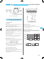
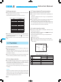
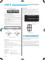
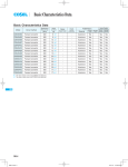
Instruction Manual
Cin
DC
input
Noise
filter
+
Input voltage [V]
Heatsink
+S
+VIN
+VOUT
+
Co
-VIN
Load
-VOUT
RC1 FG
-S
2V
max
time
Cin : External capacitor on the input side
Co : External capacitor on the output side
Input voltage range
DC-DC Converters Power Module type
t
Fig.3.1 Input voltage ripple
Range of input voltage
Input current [A]
Fig.2.1 Connection for standard use
3 Wiring Input/Output Pin
lp
Input voltage [V]
3.1 Wiring input pin
Fig.3.2 Input current characteristics
(1) External fuse
nFuse is not built-in on input side. In order to protect the unit, install the normal blow type fuse on input side.
(5) Operation with AC input
nThe CDS series handles only for the DC input.
nWhen the input voltage from a front end unit is supplied to multiple units, install a regular type fuse in each unit.
A front end unit(AC/DC converter) is required when the CDS series is operated with AC input.
Table 3.1 Recommended fuse(Normal-blow type, maximum value)
Model
CDS40048
CDS50024/CDS60024
CDS60048
Rated current
30A
75A
30A
CDS
(6) Reverse input voltage protection
nAvoid the reverse polarity input voltage.It will break the power supply.
It is possible to protect the unit from the reverse input voltage by
installing an external diode.
(2) Noise filter/Decoupling capacitor
nlnstall an external noise filter for low line-noise and for stable operation of the power supply.
nlnstall a correspondence filter, if a noise standard meeting is required or if the surge voltage may be applied to the unit.
(3) External capacitor on the input side
nlnstall an external capacitor Cin between +VIN and -VIN input pins
DC
YES
CDS
Load
CDS
Load
CDS
Load
AC
NO
AC
YES
for low line-noise and for stable operation of the power supply.
AC/DC
Converter
Fig.3.3 Use with AC input
CDS40048: more than 100 F
CDS50024/CDS60024: more than 1000 F
(a)
(b)
CDS60048: more than 470 F
nWhen the line impedance is high or the input voltage rise quickly
at start-up(less than 10 s), install a capacitor Cin between +VIN
and -VIN input pins(within 50mm from pins).
+VIN
DC IN
-VIN
+VIN
DC IN
-VIN
Fig.3.4 Reverse input voltage protection
(4) Input voltage range/Input current range
nlnput voltage ripple should be less than 2Vp-p.
nMake sure that the voltage fluctuation, including the ripple voltage, will not exceed the input voltage range.
nUse a front end unit with enough power, considering the start-up
current lp of this unit.
CDS-9