1
DC-DC Converters Power Module type
When the number of units in parallel operation increases, input current increase at the same time. Adequate wiring design for input
circuitry is required, such as circuit pattern, wiring and current ca-
Instruction Manual
nIOG signal might be unstable for one second when the units are
turned on in parallel operation.
nA sound may occur from power supply at parallel operating.
pacity for equipment.
5.3 N+1 redundant operation
In parallel operation, the maximum operative number of units is 11.
+VOUT
+S
VB
TRM
CB
-S
-VOUT
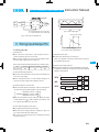
nIt is possible to set N+1 redundant operation for improving reliability of power supply system.
nPurpose of redundant operation is to ensure stable operation in
R2
R1
VR1
+
Co
Load
the event of single power supply failure.
Since extra power supply is reserved for the failure condition, so
total power of redundant operation is equal to N-1.
+VOUT
+S
VB
TRM
CB
-S
-VOUT
+
Co
+VOUT
+S
VB
TRM
CB
-S
-VOUT
+
Co
The output voltage
rises when VR1 is
adjusted for the
resistance between
and to lower.
6 Implementation
Mounting Method
6.1 Mounting method
nThe unit can be mounted in any direction. When two or more
power supplies are used side by side, position them with proper
intervals to allow enough air ventilation. Aluminum base plate temperature around each power supply should not exceed the temperature range shown in derating curve.
nAvoid placing the DC input line pattern lay out underneath the
Fig.5.2 Examples of parallel operation
unit, it will increase the line conducted noise. Make sure to leave
an ample distance between the line pattern lay out and the unit.
nWhen output voltage adjustment is not in use. TRM wiring, R1,
R2 and VR are not necessary.
nThick wire should be used for wiring between the power supply
and load, and line drop should be less than 0.3V.
nWhen the output-line impedance is high, the power supply is become unstable.
Use same length and thickness(width) wire(pattern) for the current balance improvement.
Also avoid placing the DC output line pattern underneath the unit
because it may increase the output noise. Lay out the pattern
away from the unit.
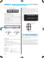
nHigh-frequency noise radiates directly from the unit to the atmosphere. Therefore, design the shield pattern on the printed circuit
board and connect its one to FG.
The shield pattern prevents noise radiation.
nThe maximum current is 25A per input pin and output pin.
nConnect each input pin for the lowest possible impedance.
Shield pattern
nWhen the number of the units in parallel operation increases, input current increases. Adequate wiring design for input circuitry
such as circuit pattern, wiring and current for equipment is required.
nConnect the sensing line and the power line by one point after
RC1
-VIN
-VOUT
connecting each power supply's sensing pins(+S, -S). In multiple
operation, sensing wires should be connected between each
+VIN
Shield pattern
+VOUT
units for the muster connection to a load.
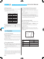
nOutput current should be 10% or more of the total of the rated output current in parallel operation.
If less than 10%, the IOG signal might become unstable, and out-
Fig.6.1 Shield pattern lay out(bottom view)
put voltage slightly increasing(max5%).
CDS-13
CDS