1
User’s Manual of MGSW-28240F
1
User’s Manual of MGSW-28240F
Trademarks
Copyright © PLANET Technology Corp. 2014.
Contents are subject to revision without prior notice.
PLANET is a registered trademark of PLANET Technology Corp.
All other trademarks belong to their respective owners.
Disclaimer
PLANET Technology does not warrant that the hardware will work properly in all environments and applications, and makes no
warranty and representation, either implied or expressed, with respect to the quality, performance, merchantability, or fitness for
a particular purpose. PLANET has made every effort to ensure that this User's Manual is accurate; PLANET disclaims liability
for any inaccuracies or omissions that may have occurred.
Information in this User's Manual is subject to change without notice and does not represent a commitment on the part of
PLANET. PLANET assumes no responsibility for any inaccuracies that may be contained in this User's Manual. PLANET makes
no commitment to update or keep current the information in this User's Manual, and reserves the right to make improvements to
this User's Manual and/or to the products described in this User's Manual, at any time without notice.
If you find information in this manual that is incorrect, misleading, or incomplete, we would appreciate your comments and
suggestions.
FCC Warning
This equipment has been tested and found to comply with the limits for a Class A digital device, pursuant to Part 15 of the FCC
Rules. These limits are designed to provide reasonable protection against harmful interference when the equipment is operated
in a commercial environment. This equipment generates, uses, and can radiate radio frequency energy and, if not installed and
used in accordance with the Instruction manual, may cause harmful interference to radio communications. Operation of this
equipment in a residential area is likely to cause harmful interference in which case the user will be required to correct the
interference at his own expense.
CE Mark Warning
This is a Class A product. In a domestic environment, this product may cause radio interference, in which case the user may be
required to take adequate measures.
Energy Saving Note of the Device
This power required device does not support Standby mode operation. For energy saving, please remove the power cable to
disconnect the device from the power circuit. In view of saving the energy and reducing the unnecessary power consumption, it
is strongly suggested to remove the power connection for the device if this device is not intended to be active.
WEEE Warning
To avoid the potential effects on the environment and human health as a result of the presence of
hazardous substances in electrical and electronic equipment, end users of electrical and electronic
equipment should understand the meaning of the crossed-out wheeled bin symbol. Do not dispose of
WEEE as unsorted municipal waste and have to collect such WEEE separately.
Revision
PLANET 24-Port 100/1000Base-X SFP + 4-Port 10G SFP+ L2/L4 Managed Metro Ethernet Switch User's Manual
FOR MODEL: MGSW-28240F
REVISION: 1.1 (March, 2014)
Part No: EM-MGSW-28240F_v1.1 (2080-A97020-001)
2
User’s Manual of MGSW-28240F
TABLE OF CONTENTS
1. INTRODUCTION.................................................................................................................. 22
1.1 Packet Contents .........................................................................................................................................22
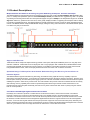
1.2 Product Descriptions .................................................................................................................................23
1.3 How to Use This Manual ............................................................................................................................26
1.4 Product Features........................................................................................................................................27
1.5 Product Specifications ..............................................................................................................................30
2. INSTALLATION ................................................................................................................... 33
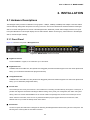
2.1 Hardware Descriptions ..............................................................................................................................33
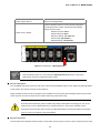
2.1.1 Front Panel ..........................................................................................................................................................33
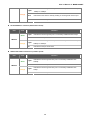
2.1.2 LED Indications ...................................................................................................................................................35
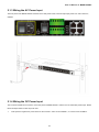
2.1.3 Wiring the AC Power Input...................................................................................................................................37
2.1.4 Wiring the DC Power Input ..................................................................................................................................37
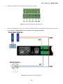
2.1.5 Wiring the Faulty Alarm Contact ..........................................................................................................................38
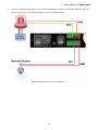
2.1.6 Wiring the Digital Input / Output...........................................................................................................................39
2.2 Installing the Managed Switch ..................................................................................................................42
2.2.1 Desktop Installation .............................................................................................................................................42
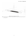
2.2.2 Rack Mounting.....................................................................................................................................................43
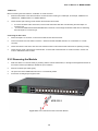
2.3 Cabling ........................................................................................................................................................45
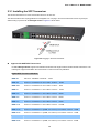
2.3.1 Installing the SFP Transceiver .............................................................................................................................46
2.3.2 Removing the Module..........................................................................................................................................48
3. SWITCH MANAGEMENT .................................................................................................... 50
3.1 Requirements..............................................................................................................................................50
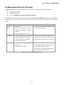
3.2 Management Access Overview .................................................................................................................51
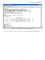
3.3 CLI Mode Management ..............................................................................................................................52
3.4 Web Management .......................................................................................................................................54
3.5 SNMP-Based Network Management.........................................................................................................55
3.6 PLANET Smart Discovery Utility ..............................................................................................................55
4. WEB CONFIGURATION ...................................................................................................... 57
4.1 Main Web Page ...........................................................................................................................................60
3
User’s Manual of MGSW-28240F
4.2 System.........................................................................................................................................................62
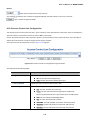
4.2.1 System Information..............................................................................................................................................62
4.2.2 IP Configuration ...................................................................................................................................................63
4.2.3 IPv6 Configuration ...............................................................................................................................................64
4.2.4 Users Configuration .............................................................................................................................................65
4.2.5 Privilege Levels ...................................................................................................................................................68
4.2.6 NTP Configuration ...............................................................................................................................................70
4.2.7 UPnP ...................................................................................................................................................................71
4.2.8 DHCP Relay ........................................................................................................................................................72
4.2.9 DHCP Relay Statistics .........................................................................................................................................74
4.2.10 CPU Load ..........................................................................................................................................................75
4.2.11 System Log ........................................................................................................................................................77
4.2.12 Detailed Log ......................................................................................................................................................78
4.2.13 Remote Syslog ..................................................................................................................................................79
4.2.14 SMTP Configuration ..........................................................................................................................................80
4.2.15 Digital Input/Output ............................................................................................................................................81
4.2.16 Faulty Alarm.......................................................................................................................................................83
4.2.17 Web Firmware Upgrade.....................................................................................................................................84
4.2.18 TFTP Firmware Upgrade ...................................................................................................................................85
4.2.19 Configuration Backup ........................................................................................................................................85
4.2.20 Configuration Upload .........................................................................................................................................87
4.2.21 Image Select......................................................................................................................................................89
4.2.22 Factory Default ..................................................................................................................................................90
4.2.23 System Reboot ..................................................................................................................................................91
4.3 Simple Network Management Protocol....................................................................................................92
4.3.1 SNMP Overview ..................................................................................................................................................92
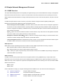
4.3.2 SNMP System Configuration ...............................................................................................................................93
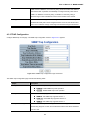
4.3.3 TRAP Configuration.............................................................................................................................................94
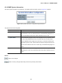
4.3.4 SNMP System Information ..................................................................................................................................96
4.3.5 SNMPv3 Configuration ........................................................................................................................................97
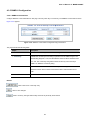
4.3.5.1 SNMPv3 Communities ..............................................................................................................................97
4.3.5.2 SNMPv3 Users ..........................................................................................................................................98
4.3.5.3 SNMPv3 Groups........................................................................................................................................99
4.3.5.4 SNMPv3 Views........................................................................................................................................100
4.3.5.5 SNMPv3 Access ......................................................................................................................................101
4.4 Port Management .....................................................................................................................................103
4.4.1 Port Configuration..............................................................................................................................................103
4.4.2 Port Statistics Overview .....................................................................................................................................106
4
User’s Manual of MGSW-28240F
4.4.3 Detailed Port Statistics.......................................................................................................................................107
4.4.4 SFP Information.................................................................................................................................................109
4.4.5 Port Mirror.......................................................................................................................................................... 110
4.5 Link Aggregation ......................................................................................................................................113
4.5.1 Static Aggregation.............................................................................................................................................. 116
4.5.2 LACP Configuration ........................................................................................................................................... 118
4.5.3 LACP System Status .........................................................................................................................................120
4.5.4 LACP Port Status...............................................................................................................................................121
4.5.5 LACP Port Statistics...........................................................................................................................................123
4.6 VLAN..........................................................................................................................................................125
4.6.1 VLAN Overview .................................................................................................................................................125
4.6.2 IEEE 802.1Q VLAN ...........................................................................................................................................126
4.6.3 VLAN Basic Information.....................................................................................................................................129
4.6.4 VLAN Port Configuration ...................................................................................................................................130
4.6.5 VLAN Membership ............................................................................................................................................134
4.6.6 VLAN Membership Status..................................................................................................................................135
4.6.7 VLAN Port Status...............................................................................................................................................137
4.6.8 Private VLAN .....................................................................................................................................................139
4.6.9 Port Isolation......................................................................................................................................................140
4.6.10 VLAN Setting Example: ...................................................................................................................................141
4.6.10.1 Two separate 802.1Q VLANs ................................................................................................................142
4.6.10.2 VLAN Trunking between two 802.1Q aware Switches...........................................................................145
4.6.10.3 Port Isolate ............................................................................................................................................147
4.6.11 MAC-based VLAN............................................................................................................................................148
4.6.12 MAC-based VLAN Status ................................................................................................................................149
4.6.13 IP Subnet-based VLAN....................................................................................................................................150
4.6.14 Protocol-based VLAN ......................................................................................................................................151
4.6.15 Protocol-based VLAN Mambership .................................................................................................................152
4.7 Spanning Tree Protocol ...........................................................................................................................154
4.7.1 Theory ...............................................................................................................................................................154
4.7.2 STP System Configuration ................................................................................................................................160
4.7.3 Bridge Status .....................................................................................................................................................163
4.7.4 CIST Port Configuration.....................................................................................................................................163
4.7.5 MSTI Priorities ...................................................................................................................................................167
4.7.6 MSTI Configuration............................................................................................................................................169
4.7.7 MSTI Ports Configuration ..................................................................................................................................170
4.7.8 Port Status .........................................................................................................................................................173
4.7.9 Port Statistics.....................................................................................................................................................175
5
User’s Manual of MGSW-28240F
4.8 Multicast ....................................................................................................................................................177
4.8.1 IGMP Snooping .................................................................................................................................................177
4.8.2 IGMP Snooping Configuration ...........................................................................................................................181
4.8.3 IGMP Snooping VLAN Configuration.................................................................................................................183
4.8.4 IGMP Snooping Port Group Filtering .................................................................................................................184
4.8.5 IGMP Snooping Status ......................................................................................................................................185
4.8.6 IGMP Group Information....................................................................................................................................187
4.8.7 IGMPv3 Information...........................................................................................................................................188
4.8.8 MLD Snooping Configuration.............................................................................................................................189
4.8.9 MLD Snooping VLAN Configuration ..................................................................................................................190
4.8.10 MLD Snooping Port Group Filtering.................................................................................................................192
4.8.11 MLD Snooping Status ......................................................................................................................................193
4.8.12 MLD Groups Information .................................................................................................................................194
4.8.13 MLDv2 Information ..........................................................................................................................................196
4.8.14 MVR.................................................................................................................................................................197
4.8.15 MVR Status......................................................................................................................................................199
4.8.16 MVR Groups Information .................................................................................................................................200
4.8.17 MVR SFM Information .....................................................................................................................................201
4.9 Quality of Service .....................................................................................................................................203
4.9.1 Understand QOS ...............................................................................................................................................203
4.9.2 Port Policing ......................................................................................................................................................204
4.9.3 Port Shaping......................................................................................................................................................205
4.9.3.1 QoS Egress Port Schedule and Shapers ................................................................................................206
4.9.4 Port Classification..............................................................................................................................................208
4.9.4.1 QoS Ingress Port Tag Classification ........................................................................................................210
4.9.5 Port Scheduler...................................................................................................................................................212
4.9.6 Port Tag Remarking ...........................................................................................................................................213
4.9.6.1 QoS Egress Port Tag Remarking.............................................................................................................214
4.9.7 Port DSCP .........................................................................................................................................................215
4.9.8 DSCP-Based QoS .............................................................................................................................................217
4.9.9 DSCP Translation ..............................................................................................................................................218
4.9.10 DSCP Classification.........................................................................................................................................221
4.9.11 QoS Control List...............................................................................................................................................222
4.9.11.1 QoS Control Entry Configuration ...........................................................................................................223
4.9.12 QoS Status ......................................................................................................................................................225
4.9.13 Storm Control Configuration ............................................................................................................................228
4.9.14 WRED..............................................................................................................................................................229
4.9.15 QoS Statistics ..................................................................................................................................................231
4.9.16 Voice VLAN Configuration ...............................................................................................................................233
4.9.17 Voice VLAN OUI Table.....................................................................................................................................235
6
User’s Manual of MGSW-28240F
4.10 Access Control Lists..............................................................................................................................236
4.10.1 Access Control List Status ...............................................................................................................................236
4.10.2 Access Control List Configuration....................................................................................................................238
4.10.3 ACE Configuration ...........................................................................................................................................240
4.10.4 ACL Ports Configuration ..................................................................................................................................249
4.10.5 ACL Rate Limiter Configuration .......................................................................................................................252
4.11 Authentication.........................................................................................................................................254
4.11.1 Understanding IEEE 802.1X Port-Based Authentication..................................................................................255
4.11.2 Authentication Configuration ............................................................................................................................259
4.11.3 Network Access Server Configuration..............................................................................................................260
4.11.4 Network Access Overview ...............................................................................................................................271
4.11.5 Network Access Statistics ................................................................................................................................272
4.11.6 Authentication Server Configuration.................................................................................................................279
4.11.7 RADIUS Overview ...........................................................................................................................................282
4.11.8 RADIUS Details ...............................................................................................................................................284
4.11.9 Windows Platform RADIUS Server Configuration............................................................................................290
4.11.10 802.1X Client Configuration ...........................................................................................................................295
4.12 Security ...................................................................................................................................................298
4.12.1 Port Limit Control .............................................................................................................................................298
4.12.2 Access Management .......................................................................................................................................303
4.12.3 Access Management Statistics ........................................................................................................................304
4.12.4 HTTPs .............................................................................................................................................................305
4.12.5 SSH .................................................................................................................................................................306
4.12.6 Port Security Status .........................................................................................................................................307
4.12.7 Port Security Detail ..........................................................................................................................................309
4.12.8 DHCP Snooping ..............................................................................................................................................310
4.12.9 DHCP Snooping Statistics ...............................................................................................................................312
4.12.10 IP Source Guard Configuration......................................................................................................................314
4.12.11 IP Source Guard Static Table .........................................................................................................................316
4.12.12 ARP Inspection ..............................................................................................................................................317
4.12.13 ARP Inspection Static Table ...........................................................................................................................319
4.13 MAC Address Table................................................................................................................................321
4.13.1 MAC Address Table Configuration ...................................................................................................................321
4.13.2 MAC Address Table Status ..............................................................................................................................323
4.13.3 Dynamic ARP Inspection Table........................................................................................................................324
4.13.4 Dynamic IP Source Guard Table......................................................................................................................325
4.14 LLDP ........................................................................................................................................................327
4.14.1 Link Layer Discovery Protocol .........................................................................................................................327
7
User’s Manual of MGSW-28240F
4.14.2 LLDP Configuration .........................................................................................................................................327
4.14.3 LLDP-MED Configuration ................................................................................................................................331
4.14.4 LLDP-MED Neighbor .......................................................................................................................................338
4.14.5 Neighbor ..........................................................................................................................................................342
4.14.6 Port Statistics...................................................................................................................................................343
4.15 Diagnostics .............................................................................................................................................345
4.15.1 Ping .................................................................................................................................................................346
4.15.2 IPv6 Ping .........................................................................................................................................................347
4.15.3 Remote IP Ping Test ........................................................................................................................................347
4.15.4 Cable Diagnostics............................................................................................................................................349
4.16 Loop Protection......................................................................................................................................350
4.16.1 Configuration ...................................................................................................................................................350
4.16.2 Status...............................................................................................................................................................352
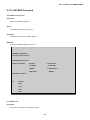
4.17 RMON.......................................................................................................................................................354
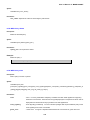
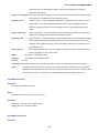
4.17.1 RMON Alarm Configuration .............................................................................................................................354
4.17.2 RMON Alarm Status.........................................................................................................................................356
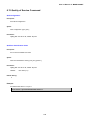
4.17.3 RMON Event Configuration .............................................................................................................................357
4.17.4 RMON Event Status.........................................................................................................................................358
4.17.5 RMON History Configuration ...........................................................................................................................359
4.17.6 RMON History Status.......................................................................................................................................359
4.17.7 RMON Statistics Configuration ........................................................................................................................361
4.17.8 RMON Statistics Status....................................................................................................................................361
4.18 PTP...........................................................................................................................................................364
4.18.1 PTP Configuration ...........................................................................................................................................364
4.18.2 PTP Status.......................................................................................................................................................365
4.19 Ring..........................................................................................................................................................367
4.19.1 MEP Configuration...........................................................................................................................................368
4.19.2 Detailed MEP Configuration ............................................................................................................................369
4.19.3 Ethernet Ring Protocol Switch .........................................................................................................................373
4.19.4 Ethernet Ring Protocol Switch Configuration...................................................................................................374
4.19.5 Ring Wizard .....................................................................................................................................................378
4.19.6 Ring Wizard Example: .....................................................................................................................................379
5. COMMAND LINE INTERFACE.......................................................................................... 382
5.1 Accessing the CLI ....................................................................................................................................382
5.2 Telnet Login ..............................................................................................................................................382
6. COMMAND LINE MODE ................................................................................................... 383
8
User’s Manual of MGSW-28240F
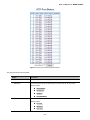
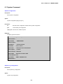
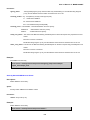
6.1 System Command ....................................................................................................................................384
System Configuration ..........................................................................................................................................384
System Log Configuration ...................................................................................................................................384
System Timezone Configuration..........................................................................................................................385
System Version ...................................................................................................................................................385
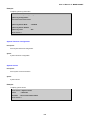
System Log Server Mode ....................................................................................................................................386
System Name......................................................................................................................................................386
System Timezone Offset .....................................................................................................................................387
System Contact ...................................................................................................................................................387
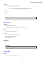
System Log Server Address ................................................................................................................................387
System Timezone Acronym .................................................................................................................................388
System DST Configuration ..................................................................................................................................388
System Location..................................................................................................................................................388
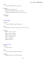
System Log Level................................................................................................................................................389
System DST Mode ..............................................................................................................................................389
System DST Start ................................................................................................................................................390
System Log Lookup.............................................................................................................................................390
System DST End .................................................................................................................................................391
System Log Clear ................................................................................................................................................391
System Reboot....................................................................................................................................................392
System DST Offset..............................................................................................................................................392
System Restore Default.......................................................................................................................................392
System Load .......................................................................................................................................................393
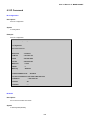
6.2 IP Command..............................................................................................................................................394
IP Configuration...................................................................................................................................................394
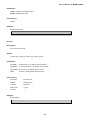
IP DHCP..............................................................................................................................................................394
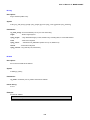
IP Setup...............................................................................................................................................................395
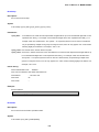
IP Ping.................................................................................................................................................................396
IP DNS ................................................................................................................................................................396
IP DNS Proxy ......................................................................................................................................................397
IPv6 AUTOCINFIG ..............................................................................................................................................397
IPv6 Setup...........................................................................................................................................................398
IPv6 State ............................................................................................................................................................398
IPv6 Ping6 ...........................................................................................................................................................399
IP NTP Configuration...........................................................................................................................................399
IP NTP Mode .......................................................................................................................................................400
IP NTP Server Add ..............................................................................................................................................401
IP NTP Server IPv6 Add ......................................................................................................................................401
IP NTP Server Delete ..........................................................................................................................................402
9
User’s Manual of MGSW-28240F
6.3 Port Management Command...................................................................................................................403
Port Configuration ...............................................................................................................................................403
Port Mode............................................................................................................................................................403
Port Flow Control.................................................................................................................................................404
Port State.............................................................................................................................................................405
Port Maximum Frame ..........................................................................................................................................405
Port Power...........................................................................................................................................................406
Port Excessive.....................................................................................................................................................406
Port Statistics.......................................................................................................................................................407
Port VeriPHY .......................................................................................................................................................407
Port SFP..............................................................................................................................................................408
Port Description...................................................................................................................................................408
6.4 MAC Address Table Command ...............................................................................................................409
MAC Configuration ..............................................................................................................................................409
MAC Add .............................................................................................................................................................409
MAC Delete .........................................................................................................................................................410
MAC Lookup........................................................................................................................................................410
MAC Age Time .................................................................................................................................................... 411
MAC Learning ..................................................................................................................................................... 411
MAC Dump..........................................................................................................................................................412
MAC Statistics .....................................................................................................................................................413
MAC Flush...........................................................................................................................................................413
6.5 VLAN Configuration Command ..............................................................................................................414
VLAN Configuration.............................................................................................................................................414
VLAV PVID ..........................................................................................................................................................415
VLAN Frame Type ...............................................................................................................................................415
VLAN Ingress Filter .............................................................................................................................................416
VLAN Mode .........................................................................................................................................................416
VLAN Link Type...................................................................................................................................................417
VLAN Q-in-Q Mode .............................................................................................................................................417
VLAN Ethernet Type............................................................................................................................................418
VLAN untagVID ...................................................................................................................................................418
VLAN Add............................................................................................................................................................419
VLAN Forbidden Add...........................................................................................................................................419
VLAN Delete........................................................................................................................................................420
VLAN Forbidden Delete.......................................................................................................................................420
VLAN Forbidden Lookup .....................................................................................................................................421
VLAN Lookup ......................................................................................................................................................421
VLAN Name Add .................................................................................................................................................422
10
User’s Manual of MGSW-28240F
VLAN Name Delete .............................................................................................................................................422
VLAN Name Lookup............................................................................................................................................423
VLAN Status ........................................................................................................................................................423
6.6 Private VLAN Configuration Command .................................................................................................425
PVLAN Configuration ..........................................................................................................................................425
PVLAN Add .........................................................................................................................................................426
PVLAN Delete .....................................................................................................................................................426
PVLAN Lookup....................................................................................................................................................426
PVLAN Isolate .....................................................................................................................................................427
6.7 Security Command...................................................................................................................................428
Security Switch User Configuration .....................................................................................................................428
Security Switch User Add ....................................................................................................................................428
Security Switch User Delete ................................................................................................................................429
Security Switch Privilege Level Configuration .....................................................................................................429
Security Switch Privilege Level Group.................................................................................................................429
Security Switch Privilege Level Current...............................................................................................................430
Security Switch Auth Configuration .....................................................................................................................430
Security Switch Auth Method...............................................................................................................................431
Security Switch SSH Configuration .....................................................................................................................432
Security Switch SSH Mode..................................................................................................................................432
Security Switch HTTPs Configuration .................................................................................................................433
Security Switch HTTPs Mode..............................................................................................................................433
Security Switch HTTPs Redirect .........................................................................................................................434
Security Switch Access Configuration .................................................................................................................434
Security Switch Access Mode..............................................................................................................................435
Security Switch Access Add ................................................................................................................................435
Security Switch Access IPv6 Add ........................................................................................................................436
Security Switch Access Delete ............................................................................................................................436
Security Switch Access Lookup...........................................................................................................................437
Security Switch Access Clear ..............................................................................................................................437
Security Switch Access Statistics ........................................................................................................................438
Security Switch SNMP Configuration ..................................................................................................................438
Security Switch SNMP Mode...............................................................................................................................438
Security Switch SNMP Version............................................................................................................................439
Security Switch SNMP Read Community ............................................................................................................439
Security Switch SNMP Write Community ............................................................................................................440
Security Switch SNMP Trap Mode.......................................................................................................................440
Security Switch SNMP Trap Version....................................................................................................................441
Security Switch SNMP Trap Community .............................................................................................................442
11
User’s Manual of MGSW-28240F
Security Switch SNMP Trap Destination..............................................................................................................442
Security Switch SNMP Trap IPv6 Destination .....................................................................................................442
Security Switch SNMP Trap Authentication Failure .............................................................................................443
Security Switch SNMP Trap Link-up....................................................................................................................444
Security Switch SNMP Trap Inform Mode ...........................................................................................................444
Security Switch SNMP Trap Inform Timeout........................................................................................................445
Security Switch SNMP Trap Inform Retry Times .................................................................................................445
Security Switch SNMP Trap Probe Security Engine ID .......................................................................................446
Security Switch SNMP Trap Security Engine ID..................................................................................................446
Security Switch SNMP Trap Security Name ........................................................................................................447
Security Switch SNMP Engine ID........................................................................................................................447
Security Switch SNMP Community Add ..............................................................................................................447
Security Switch SNMP Community Delete ..........................................................................................................448
Security Switch SNMP Community Lookup.........................................................................................................448
Security Switch SNMP User Add .........................................................................................................................449
Security Switch SNMP User Delete.....................................................................................................................450
Security Switch SNMP User Changekey .............................................................................................................450
Security Switch SNMP User Lookup ...................................................................................................................451
Security Switch SNMP Group Add.......................................................................................................................451
Security Switch SNMP Group Delete ..................................................................................................................452
Security Switch SNMP Group Lookup .................................................................................................................452
Security Switch SNMP View Add.........................................................................................................................453
Security Switch SNMP View Delete.....................................................................................................................453
Security Switch SNMP View Lookup ...................................................................................................................454
Security Switch SNMP Access Add .....................................................................................................................454
Security Switch SNMP Access Delete .................................................................................................................455
Security Switch SNMP Access Lookup................................................................................................................456
Security Switch RMON Statistics Add..................................................................................................................456
Security Switch RMON Statistics Delete..............................................................................................................456
Security Switch RMON Statistics Lookup ............................................................................................................457
Security Switch RMON History Add.....................................................................................................................457
Security Switch RMON History Delete ................................................................................................................457
Security Switch RMON History Lookup ...............................................................................................................458
Security Switch RMON Alarm Add.......................................................................................................................458
Security Switch RMON Alarm Delete ..................................................................................................................459
Security Switch RMON Alarm Lookup .................................................................................................................459
Security Switch RMON Event Add.......................................................................................................................460
Security Switch RMON Event Delete ..................................................................................................................460
Security Switch RMON Event Lookup .................................................................................................................460
Security Network Psec Switch.............................................................................................................................461
12
User’s Manual of MGSW-28240F
Security Network Psec Port.................................................................................................................................461
Security Network Limit Configuration ..................................................................................................................462
Security Network Limit Mode...............................................................................................................................463
Security Network Limit Aging...............................................................................................................................463
Security Network Limit Agetime...........................................................................................................................464
Security Network Limit Port .................................................................................................................................464
Security Network Limit Limit ................................................................................................................................465
Security Network Limit Action ..............................................................................................................................466
Security Network Limit Reopen ...........................................................................................................................466
Security Network NAS Configuration...................................................................................................................467
Security Network NAS Mode ...............................................................................................................................467
Security Network NAS State................................................................................................................................468
Security Network NAS Reauthentication .............................................................................................................469
Security Network NAS ReauthPeriod ..................................................................................................................469
Security Network NAS EapolTimeout ..................................................................................................................470
Security Network NAS Agetime ...........................................................................................................................470
Security Network NAS Holdtime..........................................................................................................................471
Security Network NAS RADIUS_QoS .................................................................................................................471
Security Network NAS RADIUS_VLAN ...............................................................................................................472
Security Network NAS Guest_VLAN ...................................................................................................................473
Security Network NAS Authenticate ....................................................................................................................474
Security Network NAS Statistics..........................................................................................................................474
Security Network ACL Configuration ...................................................................................................................475
Security Network ACL Action ...............................................................................................................................475
Security Network ACL Policy ...............................................................................................................................476
Security Network ACL Rate .................................................................................................................................476
Security Network ACL Add ..................................................................................................................................477
Security Network ACL Delete ..............................................................................................................................478
Security Network ACL Lookup .............................................................................................................................479
Security Network ACL Clear ................................................................................................................................479
Security Network ACL Status...............................................................................................................................480
Security Network ACL Port State .........................................................................................................................480
Security Network DHCP Relay Configuration......................................................................................................481
Security Network DHCP Relay Mode ..................................................................................................................481
Security Network DHCP Relay Server.................................................................................................................482
Security Network DHCP Relay Information Mode ...............................................................................................482
Security Network DHCP Relay Information Policy...............................................................................................483
Security Network DHCP Relay Statistics .............................................................................................................483
Security Network DHCP Snooping Configuration ................................................................................................484
Security Network DHCP Snooping Mode ............................................................................................................484
13
User’s Manual of MGSW-28240F
Security Network DHCP Snooping Port Mode.....................................................................................................485
Security Network DHCP Snooping Statistics .......................................................................................................485
Security Network IP Source Guard Configuration ...............................................................................................486
Security Network IP Source Guard Mode............................................................................................................486
Security Network IP Source Guard Port Mode ....................................................................................................487
Security Network IP Source Guard Limit .............................................................................................................487
Security Network IP Source Guard Entry ............................................................................................................488
Security Network IP Source Guard Status...........................................................................................................488
Security Network IP Source Guard Translation ...................................................................................................489
Security Network ARP Inspection Configuration..................................................................................................489
Security Network ARP Inspection Mode ..............................................................................................................489
Security Network ARP Inspection Port Mode ......................................................................................................490
Security Network ARP Inspection Entry...............................................................................................................490
Security Network ARP Inspection Status .............................................................................................................491
Security Network ARP Inspection Translation .....................................................................................................491
Security AAA Configuration .................................................................................................................................491
Security AAA Timeout ..........................................................................................................................................493
Security AAA Deadtime .......................................................................................................................................493
Security AAA RADIUS .........................................................................................................................................494
Security AAA ACCT_RADIUS..............................................................................................................................494
Security AAA TACACS+ ......................................................................................................................................495
Security AAA Statistics.........................................................................................................................................496
6.8 Spanning Tree Protocol Command ........................................................................................................497
STP Configuration ...............................................................................................................................................497
STP Version ........................................................................................................................................................497
STP Tx Hold ........................................................................................................................................................498
STP MaxHops .....................................................................................................................................................498
STP MaxAge .......................................................................................................................................................499
STP FwdDelay ....................................................................................................................................................499
STP CName ........................................................................................................................................................500
STP BPDU Filter..................................................................................................................................................500
STP BPDU Guard................................................................................................................................................501
STP Recovery .....................................................................................................................................................501
STP Status ..........................................................................................................................................................502
STP MSTI Priority................................................................................................................................................503
STP MSTI Map....................................................................................................................................................503
STP MSTI Add.....................................................................................................................................................504
STP Port Configuration........................................................................................................................................504
STP Port Mode ....................................................................................................................................................505
STP Port Edge ....................................................................................................................................................505
14
User’s Manual of MGSW-28240F
STP Port AutoEdge .............................................................................................................................................506
STP Port P2P ......................................................................................................................................................506
STP Port RestrictedRole .....................................................................................................................................507
STP Port RestrictedTcn .......................................................................................................................................507
STP Port bpduGuard ...........................................................................................................................................508
STP Port Statistic.................................................................................................................................................508
STP Port Mcheck.................................................................................................................................................509
STP MSTI Port Configuration ..............................................................................................................................509
STP MSTI Port Cost ............................................................................................................................................510
STP MSTI Port Priority ........................................................................................................................................510
6.9 Link Aggregation Command ...................................................................................................................512
Aggregation Configuration...................................................................................................................................512
Aggregation Add..................................................................................................................................................512
Aggregation Delete..............................................................................................................................................512
Aggregation Lookup ............................................................................................................................................513
Aggregation Mode ...............................................................................................................................................513
6.10 Link Aggregation Control Protocol Command....................................................................................515
LACP Configuration.............................................................................................................................................515
LACP Mode .........................................................................................................................................................515
LACP Key............................................................................................................................................................516
LACP Prio............................................................................................................................................................516
LACP System Prio...............................................................................................................................................517
LACP Role...........................................................................................................................................................517
LACP Status ........................................................................................................................................................518
LACP Statistics ....................................................................................................................................................518
LACP Timeout .....................................................................................................................................................519
6.11 LLDP Command......................................................................................................................................520
LLDP Configuration .............................................................................................................................................520
LLDP Mode .........................................................................................................................................................520
LLDP Optional TLV..............................................................................................................................................521
LLDP Interval.......................................................................................................................................................522
LLDP Hold ...........................................................................................................................................................522
LLDP Delay .........................................................................................................................................................523
LLDP Reinit .........................................................................................................................................................523
LLDP Statistics ....................................................................................................................................................524
LLDP Info ............................................................................................................................................................524
LLDP CDP Aware ................................................................................................................................................525
6.12 LLDP MED Command ............................................................................................................................526
15
User’s Manual of MGSW-28240F
LLDP MED Configuration ....................................................................................................................................526
LLDP MED Civic..................................................................................................................................................526
LLDP MED ECS ..................................................................................................................................................527
LLDP MED Policy Delete.....................................................................................................................................528
LLDP MED Policy Add.........................................................................................................................................528
LLDP MED Port Policy ........................................................................................................................................529
LLDP MED Coordinates ......................................................................................................................................529
LLDP MED Datum ...............................................................................................................................................530
LLDP MED Fast ..................................................................................................................................................531
LLDP MED Info ...................................................................................................................................................531
6.13 Quality of Service Command ................................................................................................................532
QoS Configuration...............................................................................................................................................532
QoS Port Classification Class..............................................................................................................................532
QoS Port Classification DPL................................................................................................................................533
QoS Port Classification PCP ...............................................................................................................................533
QoS Port Classification DEI.................................................................................................................................534
QoS Port Classification Tag.................................................................................................................................534
QoS Port Classification Map................................................................................................................................535
QoS Port Classification DSCP.............................................................................................................................535
QoS Port Policer Mode........................................................................................................................................536
QoS Port Policer Rate .........................................................................................................................................536
QoS Port Policer Unit ..........................................................................................................................................537
QoS Port Policer Flow Control.............................................................................................................................537
QoS Port QueuePolicer Mode .............................................................................................................................538
QoS Port QueuePolicer Rate ..............................................................................................................................538
QoS Port Scheduler Mode...................................................................................................................................539
QoS Port Scheduler Weight ................................................................................................................................539
QoS Port QueueShaper Mode ............................................................................................................................540
QoS Port QueueShaper Rate..............................................................................................................................540
QoS Port QueueShaper Excess..........................................................................................................................541
QoS Port TagRemarking Mode............................................................................................................................541
QoS Port TagRemarking PCP .............................................................................................................................542
QoS Port TagRemarking DEI...............................................................................................................................542
QoS Port TagRemarking Map..............................................................................................................................543
QoS Port DSCP Translation ................................................................................................................................543
QoS Port DSCP Classification.............................................................................................................................544
QoS Port DSCP EgressRemark ..........................................................................................................................545
QoS DSCP Map ..................................................................................................................................................545
QoS DSCP Translation........................................................................................................................................546
QoS DSCP Trust .................................................................................................................................................546
16
User’s Manual of MGSW-28240F
QoS DSCP Classification Mode ..........................................................................................................................546
QoS DSCP EgressRemap...................................................................................................................................547
QoS Storm Unicast..............................................................................................................................................547
QoS Storm Multicast............................................................................................................................................548
QoS Storm Broadcast..........................................................................................................................................548
QoS QCL Add......................................................................................................................................................549
QoS QCL Delete..................................................................................................................................................550
QoS QCL Lookup ................................................................................................................................................551
QoS QCL Status ..................................................................................................................................................551
QoS QCL Refresh ...............................................................................................................................................551
6.14 Mirror Command ....................................................................................................................................553
Mirror Configuration.............................................................................................................................................553
Mirror Port ...........................................................................................................................................................553
Mirror Mode .........................................................................................................................................................554
6.15 Configuration Command .......................................................................................................................555
Configuration Save..............................................................................................................................................555
Configuration Load ..............................................................................................................................................555
6.16 Firmware Command...............................................................................................................................556
Firmware Load ....................................................................................................................................................556
Firmware IPv6 Load ............................................................................................................................................556
Firmware Information ..........................................................................................................................................556
Firmware Swap ...................................................................................................................................................557
6.17 UPnP Command .....................................................................................................................................558
UPnP Configuration.............................................................................................................................................558
UPnP Mode .........................................................................................................................................................558
UPnP TTL............................................................................................................................................................559
UPnP Advertising Duration ..................................................................................................................................559
6.18 MVR Command.......................................................................................................................................560
MVR Configuration ..............................................................................................................................................560
MVR Mode ..........................................................................................................................................................560
MVR VLAN Setup................................................................................................................................................561
MVR VLAN Mode ................................................................................................................................................561
MVR VLAN Port ..................................................................................................................................................562
MVR VLAN LLQI .................................................................................................................................................562
MVR VLAN Channel............................................................................................................................................563
MVR VLAN Priority..............................................................................................................................................563
MVR Immediate Leave ........................................................................................................................................563
MVR Status .........................................................................................................................................................564
17
User’s Manual of MGSW-28240F
MVR Groups........................................................................................................................................................564
MVR SFM............................................................................................................................................................564
6.19 Voice VLAN Command...........................................................................................................................566
Voice VLAN Configuration ...................................................................................................................................566
Voice VLAN Mode ...............................................................................................................................................567
Voice VLAN ID.....................................................................................................................................................568
Voice VLAN Agetime ...........................................................................................................................................568
Voice VLAN Traffic Class.....................................................................................................................................569
Voice VLAN OUI Add...........................................................................................................................................569
Voice VLAN OUI Delete.......................................................................................................................................570
Voice VLAN OUI Clear ........................................................................................................................................570
Voice VLAN OUI Lookup .....................................................................................................................................570
Voice VLAN Port Mode........................................................................................................................................571
Voice VLAN Security ...........................................................................................................................................571
Voice VLAN Discovery Protocol ..........................................................................................................................572
6.20 Loop Protect Command.........................................................................................................................573
Loop Protect Configuration..................................................................................................................................573
Loop Protect Mode ..............................................................................................................................................573
Loop Protect Transmit .........................................................................................................................................573
Loop Protect Shutdown .......................................................................................................................................574
Loop Protect Port Configuration ..........................................................................................................................574
Loop Protect Port Mode.......................................................................................................................................574
Loop Protect Port Action......................................................................................................................................575
Loop Protect Port Transmit..................................................................................................................................575
Loop Protect Status .............................................................................................................................................575
6.21 IPMC Command......................................................................................................................................576
IPMC Configuration .............................................................................................................................................576
IPMC Mode .........................................................................................................................................................576
IPMC Flooding.....................................................................................................................................................577
IPMC Leave Proxy ..............................................................................................................................................577
IPMC Proxy .........................................................................................................................................................578
IPMC SSM...........................................................................................................................................................578
IPMC VLAN Add..................................................................................................................................................579
IPMC VLAN Delete..............................................................................................................................................579
IPMC State ..........................................................................................................................................................580
IPMC Querier ......................................................................................................................................................580
IPMC Compatibility ..............................................................................................................................................581
IPMC Fastleave...................................................................................................................................................581
IPMC Throttling ...................................................................................................................................................582
18
User’s Manual of MGSW-28240F
IPMC Filtering......................................................................................................................................................583
IPMC Router........................................................................................................................................................583
IPMC Status ........................................................................................................................................................584
IPMC Group ........................................................................................................................................................584
IPMC Version ......................................................................................................................................................585
IPMC SFM...........................................................................................................................................................585
IPMC Parameter RV............................................................................................................................................585
IPMC Parameter QI.............................................................................................................................................586
IPMC Parameter QRI ..........................................................................................................................................586
IPMC Parameter LLQI .........................................................................................................................................587
IPMC Parameter URI ..........................................................................................................................................587
6.22 VLAN Control List Command................................................................................................................589
VCL MAC-based VLAN Configuration .................................................................................................................589
VCL MAC-based VLAN Add ................................................................................................................................589
VCL MAC-based VLAN Delete ............................................................................................................................589
VCL Stasus..........................................................................................................................................................590
VCL Protocol-based VLAN Add Ethernet II .........................................................................................................590
VCL Protocol-based VLAN Add SNAP ................................................................................................................590
VCL Protocol-based VLAN Add LLC ...................................................................................................................591
VCL Protocol-based VLAN Delete Ethernet II .....................................................................................................591
VCL Protocol-based VLAN Delete SNAP ............................................................................................................591
VCL Protocol-based VLAN Delete LLC ...............................................................................................................592
VCL Protocol-based VLAN Add ...........................................................................................................................592
VCL Protocol-based VLAN Delete.......................................................................................................................592
VCL Protocol-based VLAN Configuration ............................................................................................................593
VCL IP Subnet-based Vlan Configuration............................................................................................................593
VCL IP Subnet-based Vlan Add...........................................................................................................................593
VCL IP Subnet-based Vlan Delete ......................................................................................................................593
6.23 SMTP Command .....................................................................................................................................595
SMTP Configuration ............................................................................................................................................595
SMTP Mode ........................................................................................................................................................595
SMTP Server.......................................................................................................................................................595
SMTP Auth ..........................................................................................................................................................596
SMTP Auth_user .................................................................................................................................................596
SMTP Auth_pass.................................................................................................................................................597
SMTP Mail from...................................................................................................................................................597
SMTP Mail Subject ..............................................................................................................................................597
SMTP Mail to 1....................................................................................................................................................598
SMTP Mail to 2....................................................................................................................................................598
19
User’s Manual of MGSW-28240F
SMTP Test ...........................................................................................................................................................598
6.24 DIDO Command......................................................................................................................................599
DIDO DI Act.........................................................................................................................................................599
DIDO DI Desciption .............................................................................................................................................599
DIDO DI Enable...................................................................................................................................................600
DIDO DO Act .......................................................................................................................................................600
DIDO DO Enable.................................................................................................................................................601
DIDO DO Port Alarm ...........................................................................................................................................601
DIDO DO Power Alarm........................................................................................................................................602
DIDO Fault Act ....................................................................................................................................................602
DIDO Fault Enable ..............................................................................................................................................603
DIDO Fault Port Alarm.........................................................................................................................................603
DIDO Fault Power Alarm .....................................................................................................................................603
6.25 Show Command .....................................................................................................................................604
Show Access .......................................................................................................................................................604
Show ACL............................................................................................................................................................604
Show Aggregation ...............................................................................................................................................604
Show ARP ...........................................................................................................................................................604
Show Auth ...........................................................................................................................................................605
Show DHCP Relay ..............................................................................................................................................605
Show HTTPs .......................................................................................................................................................605
Show IGMP .........................................................................................................................................................605
Show IP ...............................................................................................................................................................605
Show LACP .........................................................................................................................................................606
Show Limit Control ..............................................................................................................................................606
Show LLDP .........................................................................................................................................................606
Show LLDP-MED ................................................................................................................................................606
Show Loop Protect ..............................................................................................................................................607
Show MAC ..........................................................................................................................................................607
Show Mirror .........................................................................................................................................................607
Show MVR ..........................................................................................................................................................607
Show Port............................................................................................................................................................607
Show Privilege.....................................................................................................................................................608
Show Private VLAN .............................................................................................................................................608
Show QoS ...........................................................................................................................................................608
Show SNMP ........................................................................................................................................................608
Show SSH ...........................................................................................................................................................609
Show System ......................................................................................................................................................609
Show Timezone...................................................................................................................................................609
20
User’s Manual of MGSW-28240F
Show UPnP .........................................................................................................................................................609
Show Users .........................................................................................................................................................609
Show VLAN .........................................................................................................................................................610
Show Voice VLAN ...............................................................................................................................................610
Show Firmware ...................................................................................................................................................610
Show STP ...........................................................................................................................................................610
6.26 MEP Command .......................................................................................................................................611
mep config........................................................................................................................................................... 611
mep peer ............................................................................................................................................................. 611
mep cc.................................................................................................................................................................612
6.27 ERPS Command .....................................................................................................................................613
erps add ..............................................................................................................................................................613
erps mep .............................................................................................................................................................613
erps vlan..............................................................................................................................................................614
erps rpl ................................................................................................................................................................614
erps hold off time out ...........................................................................................................................................615
erps guard-timeout ..............................................................................................................................................616
erps wtr-timeout...................................................................................................................................................616
erps delete...........................................................................................................................................................617
erps topologychange ...........................................................................................................................................617
erps configuration ................................................................................................................................................618
7. SWITCH OPERATION ....................................................................................................... 619
7.1 Address Table ...........................................................................................................................................619
7.2 Learning ....................................................................................................................................................619
7.3 Forwarding & Filtering .............................................................................................................................619
7.4 Store-and-Forward ...................................................................................................................................619
7.5 Auto-Negotiation ......................................................................................................................................620
8. TROUBLE SHOOTING...................................................................................................... 621
APPENDEX A ........................................................................................................................ 623
A.1 Switch's Data RJ-45 Pin Assignments - 1000Mbps, 1000Base-T ........................................................623
A.2 10/100Mbps, 10/100Base-TX ...................................................................................................................623
APPENDEX B: GLOSSARY.................................................................................................. 625
21
User’s Manual of MGSW-28240F
1. INTRODUCTION
PLANET MGSW-28240F is a 24-port 100/1000Base-X SFP + 4-port 10G SFP+ L2/L4 Managed Metro Ethernet Switch. The
MGSW-28240F is all multiple Gigabit SFP mini-GBIC slots switch plus four Gigabit Copper combo ports with connective ability
and robust layer 2 features. The descriptions of the MGSW-28240F is shown below:
MGSW-28240F 24-port 100/1000Base-X SFP + 4-port 10G SFP+ L2/L4 Managed Metro Ethernet Switch
(-10~60 degrees C)
“Managed Switch” mentioned in this User’s Manual refers to the MGSW-28240F.
1.1 Packet Contents
Open the box of the Managed Switch and carefully unpack it. The box should contain the following items:
The MGSW-28240F
X1
Quick Installation Guide
X1
User’s Manual CD
X1
DB9 to RJ-45 Consol Cable
X1
Rubber Feet
X4
Rack Mount Accessory Kit
X1
AC Power Cord
X1
Dust Cap
X33
If any of these are missing or damaged, please contact your dealer immediately. If possible, retain the carton including the
original packing material, and use them again to repack the product in case there is a need to return it to us for repair.
22
User’s Manual of MGSW-28240F
1.2 Product Descriptions
Multiple SFP Fiber Port Switch for Increasing Long-reach Networking of Enterprise, Telecoms and Campus
The MGSW-28240F is equipped with advanced management functions and provides 24 100/1000Mbps dual speed SFP fiber
ports, 4 1/10Gbps dual speed fiber ports and 4 10/100/1000Mbps TP/SFP ports delivered in a rugged strong case. It is capable
of providing non-blocking switch fabric and wire-speed throughput as high as 128Gbps in the temperature range from -10 to 60
degrees C without any packet loss and CRC error, which greatly simplify the tasks of upgrading the enterprise LAN for catering
to increasing bandwidth demands. The MGSW-28240F is specially designed for service provider to deliver profitable Ethernet
network. The MGSW-28240F adopts “Front Access” design, making the wiring and maintenance of the MGSW-28240F placed
in a cabinet very easy for technicians.
Support 10Gb Ethernet
10Gb Ethernet which adopts full-duplex technology instead of low-speed, half-duplex CSMA/CD protocol, is a big leap in the
evolution of Ethernet. 10Gb Ethernet can be deployed in star or ring topologies. With 10Gb Ethernet, MGSW-28240F switch
provide broad bandwidth and powerful processing capacity. It is suitable for metropolitan networks and wide area networks.
Using MGSW-28240F switch, users can simplify network structures and reduce cost of network construction.
Optimized Design for Metropolitan Area Network Redundant Ring, Fast Recovery for Surveillance or
Industrial System
The MGSW-28240F supports redundant ring technology and features strong rapid self-recovery capability to prevent
interruptions and external intrusions. It incorporates ITU G.8032 Ethernet Ring Protection Switching technology, Spanning Tree
Protocol (802.1w RSTP), and redundant power supply system into customer’s industrial automation network to enhance system
reliability and uptime in harsh factory environments. The IGS-10020PT also protects customer’s industrial network connectivity
with switching recovery capability that is used for implementing fault tolerant ring and mesh network architectures. If the
Industrial network was interrupted accidentally, the fault recovery times could be less than 50ms to quickly bring the network
back to normal operation.
Cost-effective IPv6 Managed Gigabit Switch Solution for Metro
Nowadays, lots of electronic products or mobile devices can browse the Internet, which means the need of IP Address
increases. However, the current IPv4 network infrastructure is not capable enough to provide IP Address to each single
user/client. The situation forces the ISP to come out with the IPv6 (Internet Protocol version 6) network infrastructure. To fulfill
the demand, PLANET releases the IPv6 management Gigabit Ethernet Switch. It supports both IPv4 and IPv6 management
functions. It can work with original network structure (IPv4) and also support the new network structure (IPv6). With easy and
friendly management interfaces and plenty of management functions included, the MGSW-28240F Managed Switch is the best
choice for you to build the IPv6 FTTx edge service and for Industries to connect with IPv6 network.
23
User’s Manual of MGSW-28240F
Digital Input and Digital Output for External Alarm
PLANET MGSW-28240F supports Digital Input, and Digital Output on the front panel. This external alarm offers technicians the
ability to use Digital Input to detect, and log external device status (such as door intrusion detector) for the alarm. As Digital
Output could be used to alarm if the MGSW-28240F has port link down, link up or power failure.
Flexible and Extendable Solution
The 24 mini-GBIC slots built in the MGSW-28240F support Dual-speed, 100Base-FX and 1000Base-SX/LX SFP (Small
Form-factor Pluggable) fiber-optic modules, meaning the administrator now can flexibly choose the suitable SFP transceiver
according to the transmission distance or the transmission speed required to extend the network efficiently. The MGSW-28240F
supports SFP-DDM (Digital Diagnostic Monitor) function that can easily monitor real-time parameters of the SFP for network
administrator, such as optical output power, optical input power, temperature, laser bias current, and transceiver supply voltage.
24
User’s Manual of MGSW-28240F
AC and DC Redundant Power to Ensure Continuous Operation
PLANET MGSW-28240F is equipped with one 100~240V AC power supply unit and one additional 36 ~ 60V DC power supply
unit for redundant power supply installation. A redundant power system is also provided to enhance the reliability with either the
100~240V AC power supply unit or the DC 36 ~ 60V power supply unit. Redundant Power Systems are specifically designed to
handle the demands of high tech facilities requiring the highest power integrity. Furthermore, with the 36~ 60V DC power supply
implemented, the MGSW-28240F can be applied as the telecom level device that could be located in the electronic room.
Layer 2 / Layer 4 Fully-functioned Managed Switch for Building Automation Networking
The MGSW-28240F is ideal for applications in the factory data centers and distributions. It provides advanced Layer2 to Layer4
data switching and redundancy, Quality of Service traffic control, network access control and authentication, and Secure
Management features to protect customer’s industrial network connectivity with reliable switching recovery capability that is
suitable for implementing fault tolerant and mesh network architectures.
Powerful Security
The Managed Switch offers comprehensive Access Control List (ACL) for enforcing security to the edge. Its protection
mechanisms also comprise port-based 802.1x and MAC-based user and device authentication. The port-security is effective in
limiting the number of clients that pass through, so that network administrators can now construct highly secured corporate
networks with time and effort considerably less than before.
25
User’s Manual of MGSW-28240F
1.3 How to Use This Manual
This User Manual is structured as follows:
Section 2, INSTALLATION
The section explains the functions of the Managed Switch and how to physically install the Managed Switch.
Section 3, SWITCH MANAGEMENT
The section contains the information about the software function of the Managed Switch.
Section 4, WEB CONFIGURATION
The section explains how to manage the Managed Switch by Web interface.
Section 5, COMMAND LINE INTERFACE
The section describes how to use the Command Line interface (CLI).
Section 6, CLI MODE
The section explains how to manage the Managed Switch by Command Line interface.
Section 7, SWITCH OPERATION
The chapter explains how to do the switch operation of the Managed Switch.
Section 8, TROUBLESHOOTING
The chapter explains how to do troubleshooting of the Managed Switch.
Appendix A
The section contains cable information of the Managed Switch.
Appendix B
The section contains glossary information of the Managed Switch.
26
User’s Manual of MGSW-28240F
1.4 Product Features
Physical Port
24 100/1000Base-X SFP mini-GBIC slots
4 1/10GBase-SR/LR SFP mini-GBIC slots
4 10/100/1000Base-T Gigabit Ethernet RJ-45 combo ports
One RJ-45 Console Interface for Basic Management and Setup
Redundant Power System
Redundant Power System: 100V ~ 240V AC / Dual 36V ~ 60V DC
Active Redundant Power Failure Protection
Backup of Catastrophic Power Failure on One Supply
Fault Tolerance and Resilience.
Digital Input / Digital Output
2 Digital Input (DI)
2 Digital Output (DO)
Integrates sensors into Auto Alarm System
Transfer Alarm to IP Network via SNMP Trap
Hardware Design
-10 to 60 degrees C Operating Temperature for DC Power Input only
19-inch Rack-mountable
Relay Alarm for Port Breakdown, Power Failure
2 Thermal Fans Design
Layer 2 Features
Prevents Packet Loss with Back Pressure (Half-Duplex) and IEEE 802.3x PAUSE Frame Flow Control (Full-Duplex)
High Performance of Store-and-Forward Architecture and Runt/CRC Filtering Eliminate Erroneous Packets to
Optimize the Network Bandwidth
Storm Control Support
Broadcast / Multicast / Unicast
Supports VLAN
IEEE 802.1Q Tagged VLAN
Up to 255 VLANs Groups, Out of 4094 VLAN IDs
Provider Bridging (VLAN Q-in-Q) Support (IEEE 802.1ad)
Private VLAN Edge (PVE)
Protocol-based VLAN
MAC-based VLAN
Voice VLAN
Supports Spanning Tree Protocol
27
User’s Manual of MGSW-28240F
STP, IEEE 802.1D Spanning Tree Protocol
RSTP, IEEE 802.1w Rapid Spanning Tree Protocol
MSTP, IEEE 802.1s Multiple Spanning Tree Protocol, Spanning Tree by VLAN
BPDU Guard
Supports Link Aggregation
802.3ad Link Aggregation Control Protocol (LACP)
Cisco Ether-channel (Static Trunk)
Maximum 5 trunk Groups, up to 8 ports per Trunk Group
Up to 16Gbps Bandwidth (Duplex Mode)
Provides Port Mirror (1-to-1)
Port Mirroring to Monitor the Incoming or Outgoing Traffic on a Particular Port
Loop Protection to Avoid Broadcast Loops
Supports G.8032 Ethernet Ring Protection Switching (E.R.P.S.)
Quality of Service
Ingress Shaper and Egress Rate Limit Per Port Bandwidth Control
8 Priority Queues on All Switch Ports
Traffic Classification
-
IEEE 802.1p CoS
-
IP TOS / DSCP / IP Precedence
-
IP TCP/UDP Port Number
-
Typical Network Application
Strict Priority and Weighted Round Robin (WRR) CoS Policies
Supports QoS and In/Out bandwidth Control on Each Port
Traffic-Policing Policies on the Switch Port
DSCP Remarking
Multicast
Supports IGMP Snooping v1, v2 and v3
Supports MLD Snooping v1 and v2
Querier Mode Support
IGMP Snooping Port Filtering
MLD Snooping Port Filtering
MVR (Multicast VLAN Registration)
Security
IEEE 802.1x Port-based / MAC-based Network Access Authentication
Built-in RADIUS Client to co-operate with the RADIUS Servers
RADIUS / TACACS+ Users Access Authentication
IP-based Access Control List (ACL)
MAC-based Access Control List
Source MAC / IP Address Binding
28
User’s Manual of MGSW-28240F
DHCP Snooping to Filter Untrusted DHCP Messages
Dynamic ARP Inspection discards ARP Packets with Invalid MAC Address to IP Address Binding
IP Source Guard prevents IP spoofing attacks
IP Address Access Management to Prevent Unauthorized Intruder
Management
Switch Management Interfaces
-
Console / Telnet Command Line Interface
-
Web Switch Management
-
SNMP v1 and v2c Switch Management
-
SSH / SSL and SNMP v3 Secure Access
Four RMON Groups (History, Statistics, Alarms, and Events)
IPv6 IP Address / NTP / DNS Management
Built-in Trivial File Transfer Protocol (TFTP) Client
BOOTP and DHCP for IP Address Assignment
Firmware Upload / Download via HTTP / TFTP
DHCP Relay
DHCP Option 82
User Privilege Levels Control
NTP (Network Time Protocol)
Link Layer Discovery Protocol (LLDP) Protocol
SFP-DDM (Digital Diagnostic Monitor)
Cable Diagnostic technology provides the mechanism to detect and report potential cabling issues
Reset Button for System Reboot or Reset to Factory Default
PLANET Smart Discovery Utility for Deploy Management
29
User’s Manual of MGSW-28240F
1.5 Product Specifications
Product
MGSW-28240F
Hardware Specification
SFP/mini-GBIC Slots
24 1000Base-SX/LX/BX SFP interfaces
(Compatible with 100Base-FX SFP Transceiver)
10Gbps Fiber Ports
4 1/10GBase-SR/LR SFP+ slots
Copper Ports
4 10/ 100/1000Base-T TP/SFP combo ports
Console Port
1 x RS-232 RJ45 serial port (115200, 8, N, 1)
Switch Processing Scheme
Store-and-Forward
Switch Throughput@64Bytes
95.2Mpps
Switch Fabric
128Gbps / non-blocking
Address Table
16K entries, automatic source address learning and ageing
Share data Buffer
16Mbits
Flow Control
Jumbo Frame
Reset Button
IEEE 802.3x Pause Frame for Full-Duplex
Back pressure for Half-Duplex
10Kbytes
< 5 seconds: System reboot
> 10 seconds: Factory Default
Dimensions (W x D x H)
440 x 200 x 44.5 mm, 1U high
Weight
2.935kg
LED
Power, DC1, DC2, Fault, Ring, R.O., Link/Act and speed per Gigabit port
Power Consumption
Max. 57 watts / 197.6BTU
Power Requirement – AC
AC 100~240V, 50/60Hz 1.5A
Power Requirement – DC
-36V DC @ 1.6A, Range: -36V ~ -60V DC
2 Digital Input (DI): Level 0: -24~2.4V (± 0.1V)
Level 1: 2.4~24V (± 0.1V)
DI/DO
Input Load Current: 10mA max.
2 Digital Output (DO): Open collector to 24VDC, 100mA max. load
Layer 2 Function
Port disable / enable
Auto-Negotiation 10/100/1000Mbps full and half duplex mode selection
Port Configuration
Flow Control disable / enable
Bandwidth control on each port
Power saving mode control
Port Status
Display each port’s speed duplex mode, link status, flow control status,
auto negotiation status, trunk status
802.1Q Tagged based VLAN
VLAN
Port-based VLAN
Q-in-Q
Private VLAN Edge (PVE)
30
User’s Manual of MGSW-28240F
Up to 256 VLAN groups, out of 4094 VLAN IDs
Port Trunking
IEEE 802.3ad LACP / Static Trunk
12 groups of 16-Port trunk support
Traffic classification based, Strict priority and WRR
4-level priority for switching
QoS
- Port Number
- 802.1p priority
- 802.1Q VLAN tag
DSCP/TOS field in IP Packet Policy-Based QoS
IGMP Snooping
Access Control List
IGMP (v1/v2/v3) Snooping, up to 255 multicast Groups
IGMP Querier and Fast Leave mode support
IP-based ACL / MAC-based ACL
Up to 256 entries
Management
Basic Management Interfaces
Console, Telnet, Web Browser, SNMPv1, v2c and v3
Secure Management Interface
SSH, SSL, SNMP v3
RFC-1213 MIB-II
IF-MIB
RFC-1493 Bridge MIB
RFC-1643 Ethernet MIB
RFC-2863 Interface MIB
RFC-2665 Ether-Like MIB
SNMP MIBs
RFC-2819 RMON MIB (Group 1, 2)
RFC-2737 Entity MIB
RFC-2618 RADIUS Client MIB
RFC3411 SNMP-Frameworks-MIB
IEEE 802.1X PAE
LLDP
MAU-MIB
Standards Conformance
Regulation Compliance
FCC Part 15 Class A, CE
IEEE 802.3 10Base-T
IEEE 802.3u 100Base-TX/100Base-FX
IEEE 802.3z Gigabit SX/LX
IEEE 802.3ab Gigabit 1000Base-T
IEEE 802.3ae 10 Gigabit Ethernet
IEEE 802.3x Flow Control and Back pressure
IEEE 802.3ad Port trunk with LACP
IEEE 802.1D Spanning tree protocol
Standards Compliance
IEEE 802.1w Rapid Spanning tree protocol
IEEE 802.1s Multiple Spanning tree protocol
IEEE 802.1p Class of service
IEEE 802.1Q VLAN Tagging
IEEE 802.1x Port Authentication Network Control
IEEE 802.1ab LLDP
ITU G.8032 Ethernet Ring Protection Switching
RFC 768 UDP
RFC 793 TFTP
31
User’s Manual of MGSW-28240F
RFC 791 IP
RFC 792 ICMP
RFC 2068 HTTP
RFC 1112 IGMP version 1
RFC 2236 IGMP version 2
RFC 3376 IGMP version 3
Environment
Temperature:
-10 ~ 60 degrees C for DC power input
0 ~ 50 degrees C for AC power input
Operating
Relative Humidity: 5 ~ 95% (non-condensing)
Storage
Temperature:
-10 ~ 70 degrees C
Relative Humidity: 5 ~ 95% (non-condensing)
32
User’s Manual of MGSW-28240F
2. INSTALLATION
2.1 Hardware Descriptions
The Managed Switch provides four different running speeds – 10Mbps, 100Mbps, 1000Mbps and 10Gbps in the same Switch
and automatically distinguishes the speed of incoming connection. This section describes the hardware features of Managed
Switch. For easier management and control of the Managed Switch, familiarize yourself with its display indicators, and ports.
Front panel illustrations in this chapter display the unit LED indicators. Before connecting any network device to the Managed
Switch, read this chapter carefully.
2.1.1 Front Panel
Figure 2-1 shows the front panel of Managed Switch.
Figure 2-1: MGSW-28240F Switch Front Panel
■ Gigabit TP interface
10/100/1000Base-T Copper, RJ-45 Twist-Pair: Up to 100 meters.
■ Gigabit SFP slots
1000Base-SX/LX mini-GBIC slot, SFP (Small Factor Pluggable) Transceiver Module supports from 550 meters (Multi-mode
Fiber), up to 10/30/50/70/120 kilometers (Single Mode Fiber).
■ 10 Gigabit SFP slots
10GBase-SR/LR mini-GBIC slot, SFP (Small Factor Pluggable) Transceiver Module supports from 300 meters (Multi-mode
Fiber), up to 10 kilometers (Single Mode Fiber)
■ Console Port
The console port is a RJ-45 port connector. It is an interface for connecting a terminal directly. Through the console port, it
provides rich diagnostic information including IP Address setting, factory reset, port management, link status and system
setting. Users can use the attached DB9 to RJ-45 console cable in the package and connect to the console port on the
device. After the connection, users can run any terminal emulation program (Hyper Terminal, ProComm Plus, Telix,
Winterm and so on) to enter the startup screen of the device.
■ Reset button
On the front panel, the reset button is designed for rebooting the Managed Switch without turning off and on the power. The
following is the summary table of reset button functions:
33
User’s Manual of MGSW-28240F
Reset Button Pressed and Released
Function
< 5 sec: System Reboot
Reboot the Managed Switch
Reset the Managed Switch to Factory Default configuration.
The Managed Switch will then reboot and load the default
settings as shown below:
> 5 sec: Factory Default
。
Default Username: admin
。
Default Password: admin
。
Default IP address: 192.168.0.100
。
Subnet mask: 255.255.255.0
。
Default Gateway: 192.168.0.254
Figure 2-2: Reset button of Managed Switch
1.
Press the RESET button once and the Managed Switch will reboot automatically.
2.
Press the RESET button for 5 seconds and the Managed Switch will be back to the factory
default mode; the entire configuration will be erased.
■ AC Power Receptacle
For compatibility with electric service in most areas of the world, the Managed Switch’s power supply automatically adjusts
to line power in the range of 100-240V AC and 50/60 Hz.
Plug the female end of the power cord firmly into the receptable on the front panel of the Managed Switch. Plug the other
end of the power cord into an electric service outlet and then the power will be ready.
The device is a power-required device, which means it will not work till it is powered. If your networks
should be active all the time, please consider using UPS (Uninterrupted Power Supply) for your device.
It will prevent you from network data loss or network downtime. In some areas, installing a surge
suppression device may also help to protect your Managed Switch from being damaged by unregulated
surge or current to the Switch or the power adapter.
■ DC Power Connector
The front panel of the Managed Switch contains a power switch and a DC power connector, which accepts DC power input
34
User’s Manual of MGSW-28240F
voltage from -36V to -60V DC. Connect the power cable to the Managed Switch at the input terminal block. The size of the
two screws in the terminal block is M3.5.
■ Digital Input
The digitail input of the Managed Switch can be activated by the external sensor that senses physical changes. These
changes can include intrusion detection or certain physical change in the monitored area. For example, the external sensor
can be a door switch or an infrared motion detector.
■ Digital Output
The digital output main function is to allow the Managed Switch to trigger external devices, either automatically or by
remote control from a human operator or a software application.
2.1.2 LED Indications
System
LED
Color
Ring
Green
R.O.
Function
Lights
Indicates that Ring state is in idle mode.
Blink
Indicates that the Ring state is in protected mode.
Lights
Indicates that the switch is set to ring owner.
Green
Off
Indicates that the switch doesn’t set to ring owner.
DC1
Green
Lights
Indicates that the Switch is powered on by DC1 input.
DC2
Green
Lights
Indicates that the Switch is powered on by DC2 input.
FAN1
Green
Lights
Indicates that the FAN1 has stopped.
FAN2
Green
Lights
Indicates that the FAN2 has stopped.
Fault
Green
Lights
Indicates that Switch AC/DC or port has failed.
Lights
Indicates that the Switch is powered on.
PWR
Green
Blink
Indicates the System is running under booting procedure.
10/100/1000Base-T interfaces for port1 to port24 SFP slot
LED
Color
Function
Indicates the link through that SFP port is successfully established with speed
LNK/ACT
Lights
1000Mbps.
Green
Blink
Indicates that the switch is actively sending or receiving data over that port.
Off
Indicates that the SFP port is link down.
35
User’s Manual of MGSW-28240F
Indicates the link through that SFP port is successfully established with speed
Lights
Orange
10Mbps or 100Mbps.
Blink
Indicates that the switch is actively sending or receiving data over that port.
Off
Indicates that the SFP port is link down.
10/100/1000Base-T interfaces (Shared Port1~Port4)
LED
Color
Function
Lights
Indicates the link through that port is successfully established with 1Gbps.
Off
Indicates that the port is link down
Green
LNK/ACT
Indicates the link through that SFP port is successfully established with speed
Lights
Orange
Off
10Mbps or 100Mbps.
Indicates that the port is link down
10Base-SR/LR SFP+ interfaces for port25 to port28
LED
Color
Function
Indicates the link through that SFP port is successfully established with
Lights
Green
Off
LNK/ACT
10Gbps
Indicates that the SFP port is link down
Indicates the link through that SFP port is successfully established with
Lights
Orange
Off
1Gbps
Indicates that the SFP port is link down
36
User’s Manual of MGSW-28240F
2.1.3 Wiring the AC Power Input
The front panel of the MGSW-28240F indicates an AC inlet power socket, which accepts input power from 100 to 240V AC,
50/60Hz.
2.1.4 Wiring the DC Power Input
The 6-contact terminal block connector on the front panel of MGSW-28240F is used for two DC redundant powers input. Please
follow the steps below to insert the power wire.
1.
Insert positive / negative DC power wires into the contacts 1 and 2 for DC POWER 1, or 5 and 6 for DC POWER 2.
37
User’s Manual of MGSW-28240F
Figure 2-3: MGSW-28240F Upper Panel
2.
Tighten the wire-clamp screws for preventing the wires from loosening.
1 2
DC 1
+
-
3
4
5
6
DC 2
+
-
Figure 2-4 6-Pin Terminal Block Power Wiring Input
1. The wire gauge for the terminal block should be in the range of 12 ~ 24 AWG.
2. When performing any of the procedures like inserting the wires or tighten the wire-clamp screws,
make sure the power is OFF to prevent from getting an electric shock.
2.1.5 Wiring the Faulty Alarm Contact
The fault alarm contacts are in the middle (3 & 4) of the terminal block connector as the picture shows below. Inserting the wires,
the Managed Switch will detect the fault status of the power failure, or port link failure (available for managed model) when
Fault Alarm function has been enabled. The following illustration shows an application example for wiring the fault alarm
contacts
38
User’s Manual of MGSW-28240F
Insert the wires into the faulty alarm contacts
1. The wire gauge for the terminal block should be in the range of 12 ~ 24 AWG.
2. When performing any of the procedures like inserting the wires or tighten the wire-clamp screws, make
sure the power is OFF to prevent from getting an electric shock.
2.1.6 Wiring the Digital Input / Output
The 6-contact terminal block connector on the front panel of MGSW-28240F is used for Digital Input and Digital Output. Please
follow the steps below to insert wire.
1.
The MGSW-28240F offers two DI and DO groups. 1 and 2 are DI groups, 3 and 4 are DO groups and 5 and 6 are GND
(ground).
DI DO GND
Figure 2-5 Wiring the Redundant Power Inputs
39
User’s Manual of MGSW-28240F
2.
Tighten the wire-clamp screws for preventing the wires from loosening.
1
DI0
2
3
4
5
6
DI1 DO0 DO1 GND GND
Figure 2-6 6-Pin Terminal Block DI / DO Wiring Input
3.
There are two Digital Input groups for you to monitor two different devices. The following topology shows how to wire DI0
and DI1. We use the MGSW-28240F to be an example for describing DI application.
Figure 2-7 Wires DI0 and DI1 to Open Detector
40
User’s Manual of MGSW-28240F
4.
There are two Digital Output groups for you to sense MGSW-28240F port failure or power failure and issue a high or low
signal to external device. The following topology shows how to wire DO0 and DO1.
Figure 2-8 Wires DO0 and DO1 to Open Detector
41
User’s Manual of MGSW-28240F
2.2 Installing the Managed Switch
This section describes how to install your Managed Switch and make connections to the Managed Switch. Please read the
following topics and perform the procedures in the order being presented. To install your Managed Switch on a desktop or shelf,
simply complete the following steps.
In this paragraph, we will describe how to install the Managed Switch and the installation points attended to it.
2.2.1 Desktop Installation
To install the Managed Switch on desktop or shelf, please follow these steps:
Step1: Attach the rubber feet to the recessed areas on the bottom of the Managed Switch.
Step2: Place the Managed Switch on the desktop or the shelf near an AC/DC power source as shown in Figure 2-4.
Figure 2-4 Place the Managed Switch on the Desktop
Step3: Keep enough ventilation space between the Managed Switch and the surrounding objects.
Step4: Connect the Managed Switch to network devices.
Connect one end of a standard network cable to the 10/100/1000 RJ-45 ports on the front of the Managed Switch.
Connect the other end of the cable to the network devices such as printer servers, workstations or routers, etc.
Connecting to the Managed Switch requires UTP Category 5 network cabling with RJ-45 tips. For more
information, please see the Cabling Specification in Appendix A.
Step5: Supply power to the Managed Switch.
Connect one end of the power cable to the Managed Switch.
Connect the power plug of the power cable to a standard wall outlet.
42
User’s Manual of MGSW-28240F
When the Managed Switch receives power, the Power LED should remain solid Green.
2.2.2 Rack Mounting
To install the Managed Switch in a 19-inch standard rack, please follow the instructions described below.
Step1: Place the Managed Switch on a hard flat surface, with the front panel positioned towards the front side.
Step2: Attach the rack-mount bracket to each side of the Managed Switch with supplied screws attached to the package.
Figure 2-5 shows how to attach brackets to one side of the Managed Switch.
Figure 2-5 Attach Brackets to the Managed Switch.
You must use the screws supplied with the mounting brackets. Damage caused to the parts by
using incorrect screws would invalidate the warranty.
Step3: Secure the brackets tightly.
Step4: Follow the same steps to attach the second bracket to the opposite side.
Step5: After the brackets are attached to the Managed Switch, use suitable screws to securely attach the brackets to the rack
as shown in Figure 2-6.
43
User’s Manual of MGSW-28240F
Figure 2-6 Mounting the Managed Switch on a Rack
Step6: Proceeds with steps 4 and 5 of session 2.2.1 Desktop Installation to connect the network cabling and supply power to
the Managed Switch.
44
User’s Manual of MGSW-28240F
2.3 Cabling
10/100/1000Base-T and 100Base-FX / 1000Base-SX/LX
All 10/100/1000Base-T ports come with Auto-Negotiation capability. They automatically support 1000Base-T, 100Base-TX
and 10Base-T networks. Users only need to plug a working network device into one of the 10/100/1000Base-T ports, and
then turn on the Managed Switch. The port will automatically runs in 10Mbps, 20Mbps, 100Mbps or 200Mbps and
1000Mbps or 2000Mbps after the negotiation with the connected device. The Managed Switch has eight SFP interfaces
that support 100/1000Mbps dual speed mode (Optional multi-mode/ single-mode 100Base-FX/1000Base-SX/LX SFP
module)
Cabling
Each 10/100/1000Base-T port uses RJ-45 sockets -- similar to phone jacks -- for connection of unshielded twisted-pair
cable (UTP). The IEEE 802.3/802.3u 802.3ab Fast/Gigabit Ethernet standard requires Category 5 UTP for 100Mbps
100Base-TX. 10Base-T networks can use Cat.3, 4, 5 or 1000Base-T use 5/5e/6 UTP (see table below). Maximum distance
is 100meters (328 feet). The 100Base-FX/1000Base-SX/LX SFP slot is used as LC connector with optional SFP module.
Please see table below and know more about the cable specifications.
Port Type
Cable Type
Connector
10Base-T
Cat 3, 4, 5, 2-pair
RJ-45
100Base-TX
Cat.5 UTP, 2-pair
RJ-45
1000Base-T
Cat.5/5e/6 UTP, 2-pair
RJ-45
100Base-FX
50 / 125µm or 62.5 / 125µm multi-mode 9 / 125µm single-mode
LC (multi/single mode)
1000Base-SX/LX 50 / 125µm or 62.5 / 125µm multi-mode 9 / 125µm single-mode
LC (multi/single mode)
10GBase-SR/LR
LC (multi/single mode)
50 / 125µm or 62.5 / 125µm multi-mode 9 / 125µm single-mode
Any Ethernet devices like hubs/PCs can be connected to the Managed Switch by using straight-through wires. The two
10/100/1000Mbps ports are auto-MDI/MDI-X, which can be used on straight-through or crossover cable.
45
User’s Manual of MGSW-28240F
2.3.1 Installing the SFP Transceiver
The sections describe how to insert an SFP transceiver into an SFP slot.
The SFP transceivers are hot-pluggable and hot-swappable. You can plug in and out the transceiver to/from any SFP port
without having to power down the Managed Switch as Figure 2-9 shows below:
Figure 2-9: Plugging in the SFP Transceiver
Approved PLANET SFP Transceivers
PLANET Managed Switch supports 100/1000 dual mode with both single mode and multi-mode SFP transceivers. The
following list of approved PLANET SFP transceivers is correct at the time of publication:
Gigabit SFP Transceiver Modules
MGB-GT
SFP-Port 1000Base-T Module – 100M
MGB-SX
SFP-Port 1000Base-SX mini-GBIC module – 550M
MGB-SX2
SFP-Port 1000Base-SX mini-GBIC module – 2KM
MGB-LX
SFP-Port 1000Base-LX mini-GBIC module – 10KM
MGB-L30
SFP-Port 1000Base-LX mini-GBIC module - 30KM
MGB-L50
SFP-Port 1000Base-LX mini-GBIC module - 50KM
MGB-L70
SFP-Port 1000Base-LX mini-GBIC module - 70KM
MGB-L120
SFP-Port 1000Base-LX mini-GBIC module - 120KM
MGB-LA10
SFP-Port 1000Base-LX (WDM,TX:1310nm) mini-GBIC module - 10KM
MGB-LB10
SFP-Port 1000Base-LX (WDM,TX:1550nm) mini-GBIC module - 10KM
MGB-LA20
SFP-Port 1000Base-LX (WDM,TX:1310nm) mini-GBIC module - 20KM
MGB-LB20
SFP-Port 1000Base-LX (WDM,TX:1550nm) mini-GBIC module - 20KM
46
User’s Manual of MGSW-28240F
MGB-LA40
SFP-Port 1000Base-LX (WDM,TX:1310nm) mini-GBIC module - 40KM
MGB-LB40
SFP-Port 1000Base-LX (WDM,TX:1550nm) mini-GBIC module - 40KM
MGB-TSX
SFP-Port 1000Base-SX mini-GBIC module - 550M (-40~75 degrees C)
MGB-TLX
SFP-Port 1000Base-LX mini-GBIC module - 10KM (-40~75 degreesC)
MGB-TL30
SFP-Port 1000Base-LX mini-GBIC module - 30KM (-40~75 degrees C)
MGB-TL70
SFP-Port 1000Base-LX mini-GBIC module - 70KM (-40~75 degrees C)
Fast Ethernet SFP Transceiver Modules
MFB-FX
SFP-Port 100Base-FX Transceiver (1310nm) - 2KM
MFB-F20
SFP-Port 100Base-FX Transceiver (1310nm) - 20KM
MFB-F40
SFP-Port 100Base-FX Transceiver (1310nm) - 40KM
MFB-F60
SFP-Port 100Base-FX Transceiver (1310nm) - 60KM
MFB-FA20
SFP-Port 100Base-BX Transceiver (WDM,TX:1310nm) - 20KM
MFB-FB20
SFP-Port 100Base-BX Transceiver (WDM,TX:1550nm) - 20KM
MFB-TFX
SFP-Port 100Base-FX Transceiver (1310nm) - 2KM (-40~75 degrees C)
MFB-TF20
SFP-Port 100Base-FX Transceiver (1310nm) - 20KM (-40~75 degrees C)
1.
It is recommended to use PLANET SFPs on the Managed Switch. If you insert an SFP
transceiver that is not supported, the Managed Switch will not recognize it.
2.
Please choose the SFP transceiver which can be operated under -40~75 degrees C
temperature if the switch device is working in an 0~50 degrees C temperature environment.
1000Base-SX/LX:
Before connecting the other switches, workstation or media converter.
1.
Make sure both sides of the SFP transceiver are with the same media type, for example, 1000Base-SX to 1000Base-SX,
1000Bas-LX to 1000Base-LX.
2.
Check the fiber-optic cable type that matches the SFP transceiver model.
To connect to 1000Base-SX SFP transceiver, use the multi-mode fiber cable with one side being the male duplex LC
connector type.
To connect to 1000Base-LX SFP transceiver, use the single-mode fiber cable with one side being the male duplex LC
connector type.
Connecting the fiber cable
1.
Attach the duplex LC connector on the network cable into the SFP transceiver.
2.
Connect the other end of the cable to a device – switches with SFP installed, fiber NIC on a workstation or a media
converter.
3.
Check the LNK/ACT LED of the SFP slot on the front of the Managed Switch. Ensure that the SFP transceiver is
operating correctly.
47
User’s Manual of MGSW-28240F
100Base-FX:
Before connecting the other switches, workstation or media converter.
1.
Make sure both sides of the SFP transceiver are with the same media type or WDM pair, for example, 100Base-FX to
100Base-FX, 100Base-BX20-U to 100Base-BX20-D.
2.
Check the fiber-optic cable type that matches the SFP transceiver model.
To connect to MFB-FX SFP transceiver, use the multi-mode fiber cable with one side being the male duplex LC
connector type.
To connect to MFB-F20/F40/F60/FA20/FB20 SFP transceiver, use the single-mode fiber cable with one side being
the male duplex LC connector type.
Connecting the fiber cable
1.
Attach the duplex LC connector on the network cable into the SFP transceiver.
2.
Connect the other end of the cable to a device – switches with SFP installed, fiber NIC on a workstation or a media
converter.
3.
Check the LNK/ACT LED of the SFP slot of the switch/converter. Ensure that the SFP transceiver is operating correctly.
4.
Check the Link mode of the SFP port if the link fails. Co works with some fiber-NICs or media converters. Set the Link
mode to “100 Force” when needed.
2.3.2 Removing the Module
1.
Make sure there is no network activity by checking with the network administrator, or through the management interface of
the switch/converter (if available) to disable the port in advance.
2.
Remove the Fiber Optic Cable gently.
3.
Lift up the lever of the MGB module and turn it to a horizontal position.
4.
Pull out the module gently through the lever.
Figure 2-10: How to Pull Out the SFP Transceiver Module
48
User’s Manual of MGSW-28240F
Never pull out the module without lifting up the lever of the module and turning it to a horizontal
position. Directly pulling out the module could damage the module and the SFP module slot of the
Managed Switch.
49
User’s Manual of MGSW-28240F
3. SWITCH MANAGEMENT
This chapter explains the methods that you can use to configure management access to the Managed Switch. It describes the
types of management applications and the communication and management protocols that deliver data between your
management device (workstation or personal computer) and the system. It also contains information about port connection
options.
This chapter covers the following topics:
Requirements
Management Access Overview
Remote Telnet Access
Web Management Access
SNMP Access
Standards, Protocols, and Related Reading
3.1 Requirements
Workstations of subscribers running Windows XP/2003, Vista, Windows 7, MAC OS X, Linux, Fedora, Ubuntu or
other platform compatible with TCP/IP protocols.
Workstation installed with Ethernet NIC (Network Interface Card)
Ethernet Port connect
Network cables - Use standard network (UTP) cables with RJ45 connectors.
The above Workstation is installed with WEB Browser and JAVA runtime environment Plug-in
It is recommended to use Internet Explore 7.0 or above to access Managed Switch.
50
User’s Manual of MGSW-28240F
3.2 Management Access Overview
The Managed Switch gives you the flexibility to access and manage it using any or all of the following methods:
Remote Telnet Interface
Web browser Interface
An external SNMP-based network management application
The Remote Telnet and Web browser interface support are embedded in the Managed Switch software and are available for
immediate use. Each of these management methods has their own advantages. Table 3-1 compares the three management
methods.
Method
Advantages
Disadvantages
Security can be compromised (hackers need
Remote
Text-based
Telnet
Telnet functionality built into Windows
only know the IP address)
XP/2003, Vista, Windows 7 operating
systems
Can be accesses from any location
Web Browser
Ideal for configuring the switch remotely
Compatible with all popular browsers
Security can be compromised (hackers need
only know the IP address and subnet mask)
Can be accessed from any location
May encounter lag times on poor connections
Most visually appealing
SNMP Agent
Communicates with switch functions at
Requires SNMP manager software
Least visually appealing of all three methods
the MIB level
Based on open standards
Some settings require calculations
Security can be compromised (hackers need
only know the community name)
Table 3-1: Comparison of Management Methods
51
User’s Manual of MGSW-28240F
3.3 CLI Mode Management
There are two ways for CLI mode management, one is remote telnet, and the other is operating from console port. Remote
telnet is an IP-based protocol, and console port is for user to operate the MGSW-28240F on local only, however their operation
is the same.
The command line user interface is for performing system administration, such as displaying statistics or changing option
settings. Using this method, you can access the Managed Switch remote telnet interface from personal computer, or
workstation in the same Ethernet environment as long as you know the current IP address of the Managed Switch.
Figure 3-1: Remote Telnet and Console Port Interface Management
In Windows system, you may click “Start”, then choose “Accessories”and “Command Prompt”. Please input “telnet
192.168.0.100” and press “enter’ from your keyboard. You will see the following screen (see Figure 3-2) appear.
52
User’s Manual of MGSW-28240F
Figure 3-2: Remote Telnet Interface Main Screen of Managed Switch
For more information about using the Remote Telnet interface, refer to Chapter 5 Remote Telnet Interface Management.
53
User’s Manual of MGSW-28240F
3.4 Web Management
The Managed Switch offers management features that allow users to manage the Managed Switch from anywhere on the
network through a standard browser such as Microsoft Internet Explorer. After you set up your IP address for the Managed
Switch, you can access the Managed Switch’s Web interface applications directly in your Web browser by entering the IP
address of the Managed Switch.
Figure 3-3: Web Management
You can then use your Web browser to list and manage the Managed Switch configuration parameters from one central
location; the Web Management requires Microsoft Internet Explorer 7.0 or later.
Figure 3-4: Web Main Screen of Managed Switch
54
User’s Manual of MGSW-28240F
3.5 SNMP-Based Network Management
You can use an external SNMP-based application to configure and manage the Managed Switch, such as SNMP Network
Manager, HP Openview Network Node Management (NNM) or What’s Up Gold. This management method requires the SNMP
agent on the Managed Switch and the SNMP Network Management Station to use the same community string. This
management method, in fact, uses two community strings: the get community string and the set community string. If the
SNMP Net-work management Station only knows the set community string, it can read and write to the MIBs. However, if it only
knows the get community string, it can only read MIBs. The default getting and setting community strings for the Managed
Switch is public.
Figure 3-5: SNMP Management
3.6 PLANET Smart Discovery Utility
For easily listing the Managed Switch in your Ethernet environment, the Planet Smart Discovery Utility from user’s manual
CD-ROM is an ideal solution. The following installation instructions are to guide you to running the Planet Smart Discovery Utility.
1.Deposit the Planet Smart Discovery Utility in administrator PC.
2. Run this utility and the following screen appears.
Figure 3-6: Planet Smart Discovery Utility Screen
55
User’s Manual of MGSW-28240F
If there are two LAN cards or above in the same administrator PC, choose different LAN card by
using the “Select Adapter” tool.
3.
Press “Refresh” button for the currently connected devices in the discovery list as the screen shows
below:
Figure 3-7: Planet Smart Discovery Utility Screen
1.
This utility shows all necessary information from the devices, such as MAC Address, Device Name, firmware version, and
Device IP Subnet address. It can also assign new password, IP Subnet address and description for the devices.
2.
After setup is completed, press “Update Device”, “Update Multi” or “Update All” button to take effect. The meaning of
the 3 buttons above are shown as below:
Update Device: use current setting on one single device.
Update Multi: use current setting on choose multi-devices.
Update All: use current setting on whole devices in the list.
The same functions mentioned above also can be finding in “Option” tools bar.
3.
To click the “Control Packet Force Broadcast” function, it can allow assign new setting value to the Web Smart Switch
under a different IP subnet address.
4.
Press “Connect to Device” button and the Web login screen appears in Figure 3-4.
5.
Press “Exit” button to shutdown the planet Smart Discovery Utility.
56
User’s Manual of MGSW-28240F
4. WEB CONFIGURATION
This section introduces the configuration and functions of the Web-based management.
About Web-based Management
The Managed Switch offers management features that allow users to manage the Managed Switch from anywhere on the
network through a standard browser such as Microsoft Internet Explorer.
The Web-Based Management supports Internet Explorer 7.0. It is based on Java Applets with an aim to reduce network
bandwidth consumption, enhance access speed and present an easy viewing screen.
By default, IE7.0 or later version does not allow Java Applets to open sockets. The user has to
explicitly modify the browser setting to enable Java Applets to use network ports.
The Managed Switch can be configured through an Ethernet connection, making sure the manager PC must be set on the
same IP subnet address with the Managed Switch.
For example, the default IP address of the Managed Switch is 192.168.0.100, then the manager PC should be set at
192.168.0.x (where x is a number between 1 and 254, except 100), and the default subnet mask is 255.255.255.0.
If you have changed the default IP address of the Managed Switch to 192.168.1.1 with subnet mask 255.255.255.0 via console,
then the manager PC should be set at 192.168.1.x (where x is a number between 2 and 254) to do the relative configuration on
manager PC.
Figure 4-1-1: Web Management
57
User’s Manual of MGSW-28240F
1.
Logging on the Managed Switch
Use Internet Explorer 7.0 or above Web browser. Enter the factory-default IP address to access the Web interface. The
factory-default IP Address is shown as follows:
http://192.168.0.100
2.
When the following login screen appears, please enter the default username "admin" with password “admin” (or the
username/password you have changed via console) to login the main screen of Managed Switch. The login screen in
Figure 4-1-2 appears.
Figure 4-1-2: Login Screen
Default User name: admin
Default Password: admin
After entering the username and password, the main screen appears as shown in Figure 4-1-3.
58
User’s Manual of MGSW-28240F
Figure 4-1-3: Default Main Page
Now, you can use the Web management interface to continue the switch management or manage the Managed Switch by Web
interface. The Switch Menu on the left of the web page let you access all the commands and statistics the Managed Switch
provides.
1.
It is recommended to use Internet Explore 7.0 or above to access Managed Switch.
2.
The changed IP address take effect immediately after clicking on the Save button, you need
to use the new IP address to access the Web interface.
3.
For security reason, please change and memorize the new password after this first setup.
4.
Only accept command in lowercase letter under web interface.
59
User’s Manual of MGSW-28240F
4.1 Main Web Page
The Managed Switch provides a Web-based browser interface for configuring and managing it. This interface allows you to
access the Managed Switch using the Web browser of your choice. This chapter describes how to use the Managed Switch’s
Web browser interface to configure and manage it.
Copper Port Link Status
Main Functions Menu
SFP Port Link Status
Help Button
Main Screen
Figure 4-1-4: Main Page
Panel Display
The web agent displays an image of the Managed Switch’s ports. The Mode can be set to display different information for the
ports, including Link up or Link down. Clicking on the image of a port opens the Port Statistics page.
The port states are illustrated as follows:
State
Disabled
Link Down
RJ-45 Ports
SFP Ports
60
Link Up
User’s Manual of MGSW-28240F
Main Menu
Using the onboard web agent, you can define system parameters, manage and control the Managed Switch, and all its ports,
or monitor network conditions. Via the Web-Management, the administrator can setup the Managed Switch by selecting the
functions those listed in the Main Function. The screen in Figure 4-1-5 appears.
Figure 4-1-5: Managed Switch Main Functions Menu
61
User’s Manual of MGSW-28240F
4.2 System
Use the System menu items to display and configure basic administrative details of the Managed Switch. Under the System
the following topics are provided to configure and view the system information.
4.2.1 System Information
The System Info page provides information for the current device information. System Info page helps a switch administrator to
identify the hardware MAC address, software version and system uptime. The screen in Figure 4-2-1 appears.
Figure 4-2-1: System Information Page Screenshot
The page includes the following fields:
Object
Description
Contact
The system contact configured in Configuration | System | Information | System Contact.
Name
The system name configured in Configuration | System | Information | System Name.
Location
The system location configured in Configuration | System | Information | System
Location.
MAC Address
The MAC Address of this Managed Switch.
Power
The AC Power, Power 1 and Power 2 ON/OFF Status display.
Temperature
The temperature shows current of the switch inside temperature status.
System Date
The current (GMT) system time and date. The system time is obtained through the
62
User’s Manual of MGSW-28240F
configured SNTP Server, if any.
System Uptime
The period of time the device has been operational.
Software Version
The software version of the Managed Switch.
Software Date
The date when the switch software was produced.
Buttons
Auto-refresh
: Check this box to refresh the page automatically. Automatic refresh occurs every 3 seconds.
: Click to refresh the page.
4.2.2 IP Configuration
The IP Configuration includes the IP Address, Subnet Mask and Gateway. The Configured column is used to view or change the
IP configuration. Fill up the IP Address, Subnet Mask and Gateway for the device. The screen in Figure 4-2-2 appears.
Figure 4-2-2: IP Configuration Page Screenshot
63
User’s Manual of MGSW-28240F
The Current column is used to show the active IP configuration.
Object
Description
DHCP Client
Enable the DHCP client by checking this box. If DHCP fails and the configured IP
address is zero, DHCP will retry. If DHCP server does not respond around 35 seconds
and the configured IP address is non-zero, DHCP will stop and the configured IP
settings will be used. The DHCP client will announce the configured System Name as
hostname to provide DNS lookup.
IP Address
Provide the IP address of this switch in dotted decimal notation.
IP Mask
Provide the IP mask of this switch dotted decimal notation.
IP Router
Provide the IP address of the router in dotted decimal notation.
VLAN ID
Provide the managed VLAN ID. The allowed range is 1 through 4095.
DNS Server
Provide the IP address of the DNS Server in dotted decimal notation.
DNS Proxy
When DNS proxy is enabled, DUT will relay DNS requests to the current configured
DNS server on DUT, and reply as a DNS resolver to the client device on the network.
Buttons
: Click to save changes.
: Click to undo any changes made locally and revert to previously saved values.
: Click to renew DHCP Client. This button is only available if DHCP Client is enabled.
4.2.3 IPv6 Configuration
Configure the switch-managed IPv6 information on this page.
The Configured column is used to view or change the IPv6 configuration. The current column is used to show the active IPv6
configuration. The screen in Figure 4-2-3 appears.
Figure 4-2-3: IPv6 Configuration Page Screenshot
64
User’s Manual of MGSW-28240F
The page includes the following fields:
Object
Description
Auto Configuration
Enable IPv6 auto-configuration by checking this box. If system cannot obtain the
stateless address in time, the configured IPv6 settings will be used. The router
may delay responding to a router solicitation for a few seconds, the total time
needed to complete auto-configuration can be significantly longer.
Address
Provide the IPv6 address of this switch. IPv6 address is in 128-bit records
represented as eight fields of up to four hexadecimal digits with a colon
separating each field (:). For example, 'fe80::215:c5ff:fe03:4dc7'. The symbol '::'
is a special syntax that can be used as a shorthand way of representing multiple
16-bit groups of contiguous zeros; but it can appear only once. It can also
represent a legally valid IPv4 address. For example, '::192.1.2.34'.
Prefix
Provide the IPv6 Prefix of this switch. The allowed range is 1 to 128.
Router
Provide the IPv6 gateway address of this switch. IPv6 address is in 128-bit
records represented as eight fields of up to four hexadecimal digits with a colon
separating each field (:). For example, 'fe80::215:c5ff:fe03:4dc7'. The symbol '::'
is a special syntax that can be used as a shorthand way of representing multiple
16-bit groups of contiguous zeros; but it can appear only once. It can also
represent a legally valid IPv4 address. . For example, '::192.1.2.34'.
Buttons
: Click to save changes.
: Click to undo any changes made locally and revert to previously saved values.
: Click to renew IPv6 Auto Configuration. This button is only available if IPv6 Auto Configuration is enabled.
4.2.4 Users Configuration
This page provides an overview of the current users. Currently the only way to login as another user on the web server is to
close and reopen the browser. After setup is completed, please press “Save” button to take effect. Please login web interface
with new user name and password, the screen in Figure 4-2-4 appears.
65
User’s Manual of MGSW-28240F
Figure 4-2-4: Users Configuration Page Screenshot
The page includes the following fields:
Object
Description
User Name
The name identifying the user.
Privilege Level
The privilege level of the user. The allowed range is 1 to 15. If the privilege level
value is 15, it can access all groups, i.e. that is granted the fully control of the
device. But others value need to refer to each group privilege level. User's
privilege should be same or greater than the group privilege level to have the
access of that group. By default setting, almost group privilege level 5 has the
read-only access and privilege level 10 has the read-write access. And the
system maintenance (software upload, factory defaults and etc.) need user
privilege level 15. Generally, the privilege level 15 can be used for an
administrator account, privilege level 10 for a standard user account and privilege
level 5 for a guest account.
Buttons
: Click to add a new user.
Add / Edit User
This page configures a user – add, edit or delete user.
Figure 4-2-5: Add / Edit User Configuration Page Screenshot
66
User’s Manual of MGSW-28240F
The page includes the following fields:
Object
Description
User Name
A string identifying the user name that this entry should belong to. The allowed
string length is 1 to 32. The valid user name is a combination of letters, numbers
and underscores.
Password
The password of the user. The allowed string length is 0 to 32.
Privilege Level
The privilege level of the user. The allowed range is 1 to 15. If the privilege level
value is 15, it can access all groups, i.e. that is granted the fully control of the
device. But others value need to refer to each group privilege level. User's
privilege should be same or greater than the group privilege level to have the
access of that group. By default setting, most groups privilege level 5 has the
read-only access and privilege level 10 has the read-write access. And the
system maintenance (software upload, factory defaults and etc.) need user
privilege level 15. Generally, the privilege level 15 can be used for an
administrator account, privilege level 10 for a standard user account and privilege
level 5 for a guest account.
Buttons
: Click to save changes.
: Click to undo any changes made locally and revert to previously saved values.
: Click to undo any changes made locally and return to the Users.
: Delete the current user. This button is not available for new configurations (Add new user)
Figure 4-2-6: User Configuration Page Screenshot
If you forget the new password after changing the default password, please press the “Reset”
button on the front panel of the Managed Switch for over 10 seconds and then release it. The
current setting including VLAN will be lost and the Managed Switch will restore to the default
mode.
67
User’s Manual of MGSW-28240F
4.2.5 Privilege Levels
This page provides an overview of the privilege levels. After setup is completed, please press “Save” button to take effect.
Please login web interface with new user name and password and the screen in Figure 4-2-7 appears.
Figure 4-2-7: Privilege Levels Configuration Page Screenshot
68
User’s Manual of MGSW-28240F
The page includes the following fields:
Object
Description
Group Name
The name identifying the privilege group. In most cases, a privilege level group
consists of a single module (e.g. LACP, RSTP or QoS), but a few of them
contains more than one. The following description defines these privilege level
groups in details:
System: Contact, Name, Location, Timezone, Log.
Security: Authentication, System Access Management, Port (contains
Dot1x port, MAC based and the MAC Address Limit), ACL, HTTPS,
SSH, ARP Inspection and IP source guard.
IP: Everything except 'ping'.
Port: Everything except 'VeriPHY'.
Diagnostics: 'ping' and 'VeriPHY'.
Maintenance: CLI- System Reboot, System Restore Default, System
Password, Configuration Save, Configuration Load and Firmware Load.
Web- Users, Privilege Levels and everything in Maintenance.
Debug: Only present in CLI.
Privilege Level
Every group has an authorization Privilege level for the following sub groups:
Configuration read-only
Configuration/execute read-write
Status/statistics read-only
Status/statistics read-write (e.g. for clearing of statistics).
User Privilege should be same or greater than the authorization Privilege level to
have the access to that group.
Buttons
: Click to save changes.
: Click to undo any changes made locally and revert to previously saved values.
69
User’s Manual of MGSW-28240F
4.2.6 NTP Configuration
Configure NTP on this page.
NTP is an acronym for Network Time Protocol, a network protocol for synchronizing the clocks of computer systems. NTP
uses UDP (data grams) as transport layer. You can specify NTP Servers and set GMT Time zone. The NTP Configuration
screen in Figure 4-2-8 appears.
Figure 4-2-8: NTP Configuration Page Screenshot
The page includes the following fields:
Object
Description
Mode
Indicates the NTP mode operation. Possible modes are:
Enabled: Enable NTP mode operation. When NTP mode operation is
enabled, the agent forwards NTP messages between the clients and the
server when they are not on the same subnet domain.
Disabled: Disable NTP mode operation.
Timezone
Allow select the time zone according to current location of switch.
Server #
Provide the NTP IPv4 or IPv6 address of this switch. IPv6 address is in 128-bit
records represented as eight fields of up to four hexadecimal digits with a colon
separating each field (:).
For example, 'fe80::215:c5ff:fe03:4dc7'. The symbol '::' is a special syntax that
can be used as a shorthand way of representing multiple 16-bit groups of
contiguous zeros; but it can appear only once. It can also represent a legally valid
IPv4 address. For example, '::192.1.2.34'.
Buttons
: Click to save changes.
: Click to undo any changes made locally and revert to previously saved values.
70
User’s Manual of MGSW-28240F
4.2.7 UPnP
Configure UPnP on this page.
UPnP is an acronym for Universal Plug and Play. The goals of UPnP are to allow devices to connect seamlessly and to
simplify the implementation of networks in the home (data sharing, communications, and entertainment) and in corporate
environments for simplified installation of computer components. The UPnP Configuration screen in Figure 4-2-9 appears.
Figure 4-2-9: UPnP Configuration Page Screenshot
The page includes the following fields:
Object
Description
Mode
Indicates the UPnP operation mode. Possible modes are:
Enabled: Enable UPnP mode operation.
Disabled: Disable UPnP mode operation.
When the mode is enabled, two ACEs are added automatically to trap UPNP
related packets to CPU. The ACEs are automatically removed when the mode is
disabled.
TTL
The TTL value is used by UPnP to send SSDP advertisement messages. Valid
values are in the range of 1 to 255.
Advertising Duration
The duration, carried in SSDP packets, is used to inform a control point or control
points how often it or they should receive a SSDP advertisement message from
this switch. If a control point does not receive any message within the duration, it
will think that the switch no longer exists. Due to the unreliable nature of UDP, in
the standard it is recommended that such refreshing of advertisements to be
done at less than one-half of the advertising duration. In the implementation, the
switch sends SSDP messages periodically at the interval one-half of the
advertising duration minus 30 seconds. Valid values are in the range 100 to
86400.
Buttons
: Click to save changes.
: Click to undo any changes made locally and revert to previously saved values.
71
User’s Manual of MGSW-28240F
Figure 4-2-10: UPnP Devices shows on Windows My Network Places
4.2.8 DHCP Relay
Configure DHCP Relay on this page. DHCP Relay is used to forward and to transfer DHCP messages between the clients and
the server when they are not on the same subnet domain.
The DHCP option 82 enables a DHCP relay agent to insert specific information into a DHCP request packets when forwarding
client DHCP packets to a DHCP server and remove the specific information from a DHCP reply packets when forwarding server
DHCP packets to a DHCP client. The DHCP server can use this information to implement IP address or other assignment
policies. Specifically the option works by setting two sub-options:
Circuit ID (option 1)
Remote ID (option2).
The Circuit ID sub-option is supposed to include information specific to which circuit the request came in on.
The Remote ID sub-option was designed to carry information relating to the remote host end of the circuit.
The definition of Circuit ID in the switch is 4 bytes in length and the format is "vlan_id" "module_id" "port_no". The parameter of
"vlan_id" is the first two bytes representing the VLAN ID. The parameter of "module_id" is the third byte for the module ID (in
standalone switch it always equals 0, in stackable switch it means switch ID). The parameter of "port_no" is the fourth byte and it
72
User’s Manual of MGSW-28240F
means the port number.
The Remote ID is 6 bytes in length, and the value is equal the DHCP relay agent’s MAC address. The DHCP Relay
Configuration screen in Figure 4-2-11 appears.
Figure 4-2-11: DHCP Relay Configuration Page Screenshot
The page includes the following fields:
Object
Description
Relay Mode
Indicates the DHCP relay mode operation. Possible modes are:
Enabled: Enable DHCP relay mode operation. When enable DHCP relay
mode operation, the agent forward and to transfer DHCP messages between
the clients and the server when they are not on the same subnet domain.
And the DHCP broadcast message won't flood for security considered.
Disabled: Disable DHCP relay mode operation.
Relay Server
Indicates the DHCP relay server IP address. A DHCP relay agent is used to
forward and to transfer DHCP messages between the clients and the server
when they are not on the same subnet domain.
Relay Information
Mode
Indicates the DHCP relay information mode option operation. Possible modes
are:
Enabled: Enable DHCP relay information mode operation. When enable
DHCP relay information mode operation, the agent insert specific information
(option82) into a DHCP message when forwarding to DHCP server and
remove it from a DHCP message when transferring to DHCP client. It only
works under DHCP relay operation mode enabled.
Disabled: Disable DHCP relay information mode operation.
Relay Information
Policy
Indicates the DHCP relay information option policy. When enable DHCP relay
information mode operation, if agent receive a DHCP message that already
contains relay agent information. It will enforce the policy. And it only works under
DHCP relay information operation mode enabled. Possible policies are:
Replace: Replace the original relay information when receiving a DHCP
message that already contains it.
73
User’s Manual of MGSW-28240F
Keep: Keep the original relay information when receiving a DHCP message
that already contains it.
Drop: Drop the package when receiving a DHCP message that already
contains relay information.
Buttons
: Click to save changes.
: Click to undo any changes made locally and revert to previously saved values.
4.2.9 DHCP Relay Statistics
This page provides statistics for DHCP relay. The DHCP Relay Statistics screen in Figure 4-2-12 appears.
Figure 4-2-12: DHCP Relay Statistics Page Screenshot
The page includes the following fields:
Server Statistics
Object
Description
Transmit to Server
The number of packets that are relayed from client to server.
Transmit Error
The number of packets that resulted in errors while being sent to clients.
Receive form Server
The number of packets received from server.
Receive Missing Agent
The number of packets received without agent information options.
Option
Receive Missing
The number of packets received with the Circuit ID option missing.
Circuit ID
Receive Missing
The number of packets received with the Remote ID option missing.
Remote ID
Receive Bad Circuit ID
The number of packets whose Circuit ID option did not match known circuit ID.
74
User’s Manual of MGSW-28240F
Receive Bad Remote
The number of packets whose Remote ID option did not match known Remote
ID.
ID
Client Statistics
Object
Description
Transmit to Client
The number of relayed packets from server to client.
Transmit Error
The number of packets that resulted in error while being sent to servers.
Receive form Client
The number of received packets from server.
Receive Agent Option
The number of received packets with relay agent information option.
Replace Agent Option
The number of packets which were replaced with relay agent information option.
Keep Agent Optin
The number of packets whose relay agent information was retained.
Drop Agent Option
The number of packets that were dropped which were received with relay agent
information.
Buttons
Auto-refresh
: Check this box to refresh the page automatically. Automatic refresh occurs every 3 seconds.
: Click to refresh the page immediately.
: Clear all statistics.
4.2.10 CPU Load
This page displays the CPU load, using a SVG graph.
The load is measured as average over the last 100ms, 1sec and 10 seconds intervals. The last 120 samles are graphed, and
the last numbers are displayed as text as well.
In order to display the SVG graph, your browser must support the SVG format. Consult the SVG Wiki for more information on
browser support. Specifically, at the time of writing, Microsoft Internet Explorer will need to have a plugin installed to support
SVG. The CPU Load screen in Figure 4-2-13 appears.
75
User’s Manual of MGSW-28240F
Figure 4-2-13: CPU Load Page Screenshot
Buttons
Auto-refresh
: Check this box to refresh the page automatically. Automatic refresh occurs every 3 seconds.
If your browser cannot display anything on this page, please download Adobe SVG tool and
install it in your computer.
76
User’s Manual of MGSW-28240F
4.2.11 System Log
The switch system log information is provided here. The System Log screen in Figure 4-2-14 appears.
Figure 4-2-14: System Log Page Screenshot
The page includes the following fields:
Object
Description
ID
The ID (>= 1) of the system log entry.
Level
The level of the system log entry. The following level types are supported:
Info: Information level of the system log.
Warning: Warning level of the system log.
Error: Error level of the system log.
All: All levels.
Time
The time of the system log entry.
Message
The message of the system log entry.
Buttons
Auto-refresh
: Check this box to refresh the page automatically. Automatic refresh occurs every 3 seconds.
: Click to updates the system log entries, starting from the current entry ID.
: Flushes the selected log entries.
: Hide system log according to entry page. As default System Log Information shows 20 entries for one page. Hide
button can hide the system log entry that has been over one page.
: Click this button could download system log with CSV format file.
77
User’s Manual of MGSW-28240F
: Updates the system log entries, starting from the first available entry ID.
: Updates the system log entries, ending at the last entry currently displayed.
: Updates the system log entries, starting from the last entry currently displayed.
: Updates the system log entries, ending at the last available entry ID.
4.2.12 Detailed Log
The switch system detailed log information is provided here. The Detailed Log screen in Figure 4-2-15 appears.
Figure 4-2-15: Detailed Log Page Screenshot
The page includes the following fields:
Object
Description
ID
The ID (>= 1) of the system log entry.
Message
The message of the system log entry.
Buttons
: Click this button could download system log with CSV format file.
: Updates the system log entry to the current entry ID.
: Updates the system log entry to the first available entry ID
: Updates the system log entry to the previous available entry ID.
: Updates the system log entry to the next available entry ID.
: Updates the system log entry to the last available entry ID.
78
User’s Manual of MGSW-28240F
: Click this button to print out system log.
4.2.13 Remote Syslog
Configure remote syslog on this page. The Remote Syslog screen in Figure 4-2-16 appears.
Figure 4-2-16: Remote Syslog Page Screenshot
The page includes the following fields:
Object
Description
Server Mode
Indicates the server mode operation. When the mode operation is enabled, the
syslog message will send out to syslog server. The syslog protocol is based on
UDP communication and received on UDP port 514 and the syslog server will not
send acknowledgments back sender since UDP is a connectionless protocol and
it does not provide acknowledgments. The syslog packet will always send out
even if the syslog server does not exist. Possible modes are:
Enabled: Enable server mode operation.
Disabled: Disable server mode operation.
Server Address
Indicates the IPv4 host address of syslog server. If the switch provide DNS
feature, it also can be a host name.
Syslog Level
Indicates what kind of message will send to syslog server. Possible modes are:
Info: Send information, warnings and errors.
Warning: Send warnings and errors.
Error: Send errors.
Buttons
: Click to save changes.
: Click to undo any changes made locally and revert to previously saved values.
79
User’s Manual of MGSW-28240F
4.2.14 SMTP Configuration
Configure SMTP Configuration on this page. The SMTP Configuration screen in Figure 4-2-17 appears.
Figure 4-2-17: SMTP Configuration Page Screenshot
The page includes the following fields:
Object
Description
SMTP Mode
Enabled
It is for you to enable SMTP mode function. This mode offers you to configure
SMTP server and SMTP account information, system will refer it to send an
E-mail for alarm noticing
SMTP Server
It is for you to set up a specify SMTP server DNS name or IP address. If it is
inputted a DNS name, please remember to input DNS server IP address at IP
configuration page.
SMTP Port
It is for you to input the SMTP server port number. As default is "25".
SMTP Authentication
Enabled
As usual SMTP server is denied to relay a mail from a different domain, so you
have to enable this option and input your mail account and password for SMTP
sever authorizing to forward a mail from different domain.
For example, you want a SMTP server which located on mail.123.com send a
mail to mail.456.net.com.
If you want to send the mail to a SMTP server which located on the same domain
or the same SMTP server, you don't have to enable SMTP authentication.
Authentication User
Name
Authentication
Password
E-mail From
It is for you to input your mail account name.
It is for you to input your mail account password.
It is for you to input who send this mail.
80
User’s Manual of MGSW-28240F
E-mail Subject
E-mail 1 To
E-mail 2 To
It is for you to input mail subject.
It is for you to input recipient mail address.
It is for you to input secondary recipient mail address.
Buttons
: Click to test SMTP server address.
: Click to save changes.
: Click to undo any changes made locally and revert to previously saved values.
4.2.15 Digital Input/Output
Digital Input allows user can log external device (such as industrial cooler) dead or alive or something else, system will logs a
user cistomize message into system log, syslog, issue SNMP trap or issue an alarm E-mail.
Digital Output allows user to monitor the switch port and power , and let system issue a high or low signal to an external device
(such as alarm) when the monitor port or power has been failed. The Configuration screen in Figure 4-2-18 appears.
Figure 4-2-18 Windows File Selection Menu Popup
81
User’s Manual of MGSW-28240F
The page includes the following fields:
Object
Description
Enable
Checks the Enable checkbox will enable Digital Input / output function.
Unchecks the Enable checkbox will disable Digital input / output function.
Condition
As Digital Input:
Allows user selecting to High to Low or Low to High. This is means a signal
received by system is from High to Low or From Low to High, it will trigger an
action that logs a customize message or issue the message from the switch.
As Digital Output:
Allows user selecting to High to Low or Low to High. This is means that when
the switch has power failed or port failed then system will issue a High
or Low signal to an external device (such as an alarm).
Event Description
Allows user setting a customize message for Digital Input function alarming.
Event
As Digital Input:
Allows user to record alarm message to System log, syslog or issues out via
SNMP Trap or SMTP.
As default SNMP Trap and SMTP are disabled, please enable them first if you
want to issue alarm message via them.
As Digital Output:
Allows user to monitor and alarm from port fail, power fail, Digital Input 0 (DI 0)
and Digital Input 1(DI 1) which means if Digital Output has detected these
event then Digitial Output would be triggered according to the setting of
Condition.
Power Alarm
Allows user to choose which power module want to be monitored.
Port Alarm
Allows user to choose which port want to be monitored.
Buttons
: Click to save changes.
: Click to undo any changes made locally and revert to previously saved values.
82
User’s Manual of MGSW-28240F
4.2.16 Faulty Alarm
The Faulty Relay Alarm function provides the Power Failure and Port Link Down/Broken detection. With both power input 1 and
power input 2 installed and the check boxes of power 1/power 2 ticked, the FAULTY LED indicator will then be possible to light
up when any one of the power failures occurs. As for the Port Link Down/Broken detection, the FAULT LED indicator will light up
when the port failure occurs; certainly the check box beside the port must be ticked first. Please refer to the segment of ‘Wiring
the Fault Alarm Contact’ for the failure detection. The Configuration screen in Figure 4-2-19 appears.
Figure 4-2-19 Windows File Selection Menu Popup
The page includes the following fields:
Object
Description
Enable
Allows user to enable Fault Alarm function.
Record
Allows user to record alarm message to System log, syslog or issues out via
SNMP Trap or SMTP.
As default SNMP Trap and SMTP are disabled, please enable them first if you
want to issue alarm message via them.
Action
Allows user to monitor and alarm from port fail or power fail.
Power Alarm
Allows user to choose which power module want to be monitored.
Port Alarm
Allows user to choose which port want to be monitored.
Buttons
: Click to save changes.
: Click to undo any changes made locally and revert to previously saved values.
83
User’s Manual of MGSW-28240F
4.2.17 Web Firmware Upgrade
This page facilitates an update of the firmware controlling the Managed Switch. The Web Firmware Upgrade screen in Figure
4-2-20 appears.
Figure 4-2-20: Web Firmware Upgrade Page Screenshot
To open Firmware Upgrade screen perform the folling:
1.
Click System -> Web Firmware Upgrade.
2.
The Firmware Upgrade screen is displayed as in Figure 4-2-20.
3.
Click the “
4.
Select on the firmware and then click “
5.
Once the software be loaded to the system successfully, the following screen appears. The system will load the new
“button of the main page, the system would pop up the file selection menu to choose firmware.
”. The Software Upload Progress would show the file upload status.
software after reboot.
Figure 4-2-21: Software successfully Loaded Notice Screen
DO NOT Power OFF the Managed Switch until the update progress is complete.
Do not quit the Firmware Upgrade page without pressing the “OK” button after the image is
loaded. Or the system won’t apply the new firmware. User has to repeat the firmware
upgrade processes again.
84
User’s Manual of MGSW-28240F
4.2.18 TFTP Firmware Upgrade
The Firmware Upgrade page provides the functions to allow a user to update the Managed Switch firmware from the TFTP
server in the network. Before updating, make sure you have your TFTP server ready and the firmware image is on the TFTP
server. The TFTP Firmware Upgrade screen in Figure 4-2-22 appears.
Figure 4-2-22: TFTP Firmware Update Page Screenshot
The page includes the following fields:
Object
Description
TFTP Server IP
Fill in your TFTP server IP address.
Firmware File Name
The name of firmware image.
(Maximum length : 24 characters)
Buttons
: Click to upgrade firmware.
DO NOT Power OFF the Managed Switch until the update progress is complete.
Do not quit the Firmware Upgrade page without pressing the “OK” button after the image is
loaded. Or the system won’t apply the new firmware. User has to repeat the firmware
upgrade processes again.
4.2.19 Configuration Backup
This function allows backup and reload the current configuration of the Managed Switch to the local management station. The
Configuration Backup screen in Figure 4-2-23 appears.
Figure 4-2-23: Configuration Save Page Screenshot
85
User’s Manual of MGSW-28240F
Save configuration except IP Address feature is almost the same with Save configuration, except the IP address will not be
saved.
You can save/view or load the switch configuration. The configuration file is in XML format with a hierarchy of tags:
Header tags:
<?xml version="1.0"?> and <configuration>. These tags are mandatory and must be present
at the beginning of the file.
Section tags:
<platform>, <global> and <switch>. The platform section must be the first section tag and
this section must include the correct platform ID and version. The global section is optional
and includes configuration which is not related to specific switch ports. The switch section is
optional and includes configuration which is related to specific switch ports.
Module tags:
<ip>, <mac>, <port> etc. These tags identify a module controlling specific parts of the
configuration.
Group tags:
<port_table>, <vlan_table> etc. These tags identify a group of parameters, typically a table.
Parameter tags:
<mode>, <entry> etc. These tags identify parameters for the specific section, module and
group. The <entry> tag is used for table entries.
Configuration parameters are represented as attribute values. When saving the configuration from the switch, the entire
configuration including syntax descriptions is included in the file. The file may then be modified using an editor and loaded to a
Managed Switch.
The examples below show a small configuration file only including configuration of the MAC address age time and the learning
mode per port. When loading this file, only the included parameters will be changed. This means that the age time will be set to
200 and the learn mode will be set to automatic.
Save Configuration
1.
Press the “Save Configuration” button to save the current configuration in manager workstation. The following screens in
Figure 4-2-24 & 4-2-25 appear
Figure 4-2-24: File Download Screen
86
User’s Manual of MGSW-28240F
2.
Chose the file save path in management workstation.
Figure 4-2-25: File Save Screen
4.2.20 Configuration Upload
This function allows backup and reload the current configuration of the Managed Switch to the local management station. The
Configuration Upload screen in Figure 4-2-26 appears.
Figure 4-2-26: Configuration Upload Page Screenshot
Configuration Upload
1.
Click the “
” button of the main page, the system would pop up the file selection menu to choose saved
configuration.
87
User’s Manual of MGSW-28240F
Figure 4-2-27: Windows File Selection Menu Popup
2.
Select on the configuration file and then click “
3.
After down, the main screen appears “Transfer Completed”.
”,.The bottom of the browser shows the upload status.
88
User’s Manual of MGSW-28240F
4.2.21 Image Select
This function provides dual image deposit in the Managed Switch. User can select any one of the image as Active image of
Managed Switch. The Image Select screen in Figure 4-2-28 appears.
Figure 4-2-28: Image Select Page Screenshot
Button
: Click to choose Alternate Image as Activate Image.
Figure 4-2-29: Image Select Page Screenshot
Figure 4-2-30: Image Select Page Screenshot
89
User’s Manual of MGSW-28240F
Figure 4-2-31: Image Select Page Screenshot
After the system reboot, you can use the Alternate Image of Managed Switch.
4.2.22 Factory Default
You can reset the configuration of the stack switch on this page. Only the IP configuration is retained. The new configuration is
available immediately, which means that no restart is necessary. The Factory Default screen in Figure 4-2-32 appears.
Figure 4-2-32: Factory Default Page Screenshot
Buttons
: Click to reset the configuration to Factory Defaults.
Figure 4-2-33: Factory Default Page Screenshot
: Click to return to the web main page without resetting the configuration.
90
User’s Manual of MGSW-28240F
After the “Factory” button be pressed and rebooted, the system will be loaded default settings, except IP address.
To reset the Managed Switch to the Factory default setting, you can also press the hardware reset button
at the front panel for about 5 seconds. After the device is rebooted, all configurations will be loaded to
default settings to include IP address. You can login the management WEB interface within the same
subnet of 192.168.0.xx.
4.2.23 System Reboot
The Reboot page enables the device to be rebooted from a remote location. Once the Reboot button is pressed, user will
re-access the WEB interface about 60 seconds later, the System Reboot screen in Figure 4-2-34 appears.
Figure 4-2-34: System Reboot Page Screenshot
Buttons
: Click to reboot the system.
: Click to return to the web main page without reboot the system.
91
User’s Manual of MGSW-28240F
4.3 Simple Network Management Protocol
4.3.1 SNMP Overview
The Simple Network Management Protocol (SNMP) is an application layer protocol that facilitates the exchange of management
information between network devices. It is part of the Transmission Control Protocol/Internet Protocol (TCP/IP) protocol suite.
SNMP enables network administrators to manage network performance, find and solve network problems, and plan for network
growth.
An SNMP-managed network consists of three key components: Network management stations (NMSs), SNMP agents,
Management information base (MIB) and network-management protocol:
。
Network management stations (NMSs):Sometimes called consoles, these devices execute management applications
that monitor and control network elements. Physically, NMSs are usually engineering workstation-caliber computers with
fast CPUs, megapixel color displays, substantial memory, and abundant disk space. At least one NMS must be present in
each managed environment.
。
Agents:Agents are software modules that reside in network elements. They collect and store management information
such as the number of error packets received by a network element.
。
Management information base (MIB):A MIB is a collection of managed objects residing in a virtual information store.
Collections of related managed objects are defined in specific MIB modules.
。
network-management protocol:A management protocol is used to convey management information between agents
and NMSs. SNMP is the Internet community's de facto standard management protocol.
SNMP Operations
SNMP itself is a simple request/response protocol. NMSs can send multiple requests without receiving a response.
。
Get -- Allows the NMS to retrieve an object instance from the agent.
。
Set -- Allows the NMS to set values for object instances within an agent.
。
Trap -- Used by the agent to asynchronously inform the NMS of some event. The SNMPv2 trap message is designed to
replace the SNMPv1 trap message.
SNMP community
An SNMP community is the group that devices and management stations running SNMP belong to. It helps define where
information is sent. The community name is used to identify the group. A SNMP device or agent may belong to more than one
SNMP community. It will not respond to requests from management stations that do not belong to one of its communities. SNMP
default communities are:
。
Write = private
。
Read = public
Use the SNMP Menu to display or configure the Managed Switch's SNMP function. This section has the following items:
System Configuration
Configure SNMP on this page.
System Information
The system information is provided here.
SNMPv3 Communities
Configure SNMPv3 communities table on this page.
SNMPv3 Users
Configure SNMPv3 users table on this page.
92
User’s Manual of MGSW-28240F
SNMPv3 Groups
Configure SNMPv3 groups table on this page.
SNMPv3 Views
Configure SNMPv3 views table on this page.
SNMPv3 Accesses
Configure SNMPv3 accesses table on this page.
4.3.2 SNMP System Configuration
Configure SNMP on this page. The SNMP System Configuration screen in Figure 4-3-1 appears.
Figure 4-3-1: SNMP System Configuration Page Screenshot
The SNMP System Configuration page includes the following fields:
Object
Description
Mode
Indicates the SNMP mode operation. Possible modes are:
Enabled: Enable SNMP mode operation.
Disabled: Disable SNMP mode operation.
Version
Indicates the SNMP supported version. Possible versions are:
SNMP v1: Set SNMP supported version 1.
SNMP v2c: Set SNMP supported version 2c.
SNMP v3: Set SNMP supported version 3.
Read Community
Indicates the community read access string to permit access to SNMP agent.
The allowed string length is 0 to 255, and the allowed content is the ASCII
characters from 33 to 126.
The field is applicable only when SNMP version is SNMPv1 or SNMPv2c. If
SNMP version is SNMPv3, the community string will be associated with SNMPv3
communities table. It provides more flexibility to configure security name than a
SNMPv1 or SNMPv2c community string. In addition to community string, a
particular range of source addresses can be used to restrict source subnet.
Write Community
Indicates the community write access string to permit access to SNMP agent.
The allowed string length is 0 to 255, and the allowed content is the ASCII
characters from 33 to 126.
The field is applicable only when SNMP version is SNMPv1 or SNMPv2c. If
93
User’s Manual of MGSW-28240F
SNMP version is SNMPv3, the community string will be associated with SNMPv3
communities table. It provides more flexibility to configure security name than a
SNMPv1 or SNMPv2c community string. In addition to community string, a
particular range of source addresses can be used to restrict source subnet.
Engine ID
Indicates the SNMPv3 engine ID. The string must contain an even number(in
hexadecimal format) with number of digits between 10 and 64, but all-zeros and
all-'F's are not allowed. Change of the Engine ID will clear all original local users.
4.3.3 TRAP Configuration
Configure SNMP trap on this page. The SNMP trap configuration screen in Figure 4-3-2 appears.
Figure 4-3-2: SNMP Trap Configuration Page Screenshot
The SNMP Trap Configuration page includes the following fields:
Object
Description
Trap Mode
Indicates the SNMP trap mode operation. Possible modes are:
Enabled: Enable SNMP trap mode operation.
Disabled: Disable SNMP trap mode operation.
Trap Version
Indicates the SNMP trap supported version. Possible versions are:
SNMP v1: Set SNMP trap supported version 1.
SNMP v2c: Set SNMP trap supported version 2c.
SNMP v3: Set SNMP trap supported version 3.
Trap Community
Indicates the community access string when send SNMP trap packet. The
allowed string length is 0 to 255, and the allowed content is the ASCII characters
from 33 to 126.
94
User’s Manual of MGSW-28240F
Trap Destination
Address
Indicates the SNMP trap destination address. It allows a valid IP address in
dotted decimal notation ('x.y.z.w').
And it also allows a valid hostname. A valid hostname is a string drawn from the
alphabet (A-Za-z), digits (0-9), dot (.), dash (-). Spaces are not allowed, the first
character must be an alpha character, and the first and last characters must not
be a dot or a dash.
Trap Destination IPv6
Address
Indicates the SNMP trap destination IPv6 address. IPv6 address is in 128-bit
records represented as eight fields of up to four hexadecimal digits with a colon
separating each field (:). For example, 'fe80::215:c5ff:fe03:4dc7'. The symbol '::'
is a special syntax that can be used as a shorthand way of representing multiple
16-bit groups of contiguous zeros; but it can appear only once. It can also
represent a legally valid IPv4 address. For example, '::192.1.2.34'.
Trap Authentication
Failure
Indicates the SNMP entity is permitted to generate authentication failure traps.
Possible modes are:
Enabled: Enable SNMP trap authentication failure.
Disabled: Disable SNMP trap authentication failure.
Trap Link-up and
Link-down
Indicates the SNMP trap link-up and link-down mode operation. Possible modes
are:
Enabled: Enable SNMP trap link-up and link-down mode operation.
Disabled: Disable SNMP trap link-up and link-down mode operation.
Trap Inform Mode
Indicates the SNMP trap inform mode operation. Possible modes are:
Enabled: Enable SNMP trap inform mode operation.
Disabled: Disable SNMP trap inform mode operation.
Trap Inform Timeout
Indicates the SNMP trap inform timeout. The allowed range is 0 to 2147.
(seconds)
Trap Inform Retry
Indicates the SNMP trap informs retry times. The allowed range is 0 to 255.
Times
Buttons
: Click to save changes.
: Click to undo any changes made locally and revert to previously saved values.
95
User’s Manual of MGSW-28240F
4.3.4 SNMP System Information
The switch system information is provided here. The SNMP System Information screen in Figure 4-3-3 appears.
Figure 4-3-3: System Information Configuration Page Screenshot
The page includes the following fields:
Object
Description
System Contact
The textual identification of the contact person for this managed node, together
with information on how to contact this person. The allowed string length is 0 to
255, and the allowed content is the ASCII characters from 32 to 126.
System Name
An administratively assigned name for this managed node. By convention, this is
the node's fully-qualified domain name. A domain name is a text string drawn
from the alphabet (A-Za-z), digits (0-9), minus sign (-). No space characters are
permitted as part of a name. The first character must be an alpha character. And
the first or last character must not be a minus sign. The allowed string length is 0
to 255.
System Location
The physical location of this node (e.g., telephone closet, 3rd floor). The allowed
string length is 0 to 255, and the allowed content is the ASCII characters from 32
to 126.
Buttons
: Click to save changes.
: Click to undo any changes made locally and revert to previously saved values.
96
User’s Manual of MGSW-28240F
4.3.5 SNMPv3 Configuration
4.3.5.1 SNMPv3 Communities
Configure SNMPv3 communities table on this page. The entry index key is Community. The SNMPv3 Communities screen in
Figure 4-3-4 appears.
Figure 4-3-4: SNMPv3 Communities Configuration Page Screenshot
The page includes the following fields:
Object
Description
Delete
Check to delete the entry. It will be deleted during the next save.
Community
Indicates the community access string to permit access to SNMPv3 agent. The
allowed string length is 1 to 32, and the allowed content is ASCII characters from
33 to 126. The community string will be treated as security name and map a
SNMPv1 or SNMPv2c community string.
Source IP
Indicates the SNMP access source address. A particular range of source
addresses can be used to restrict source subnet when combined with source
mask.
Source Mask
Indicates the SNMP access source address mask.
Buttons
: Click to add a new community entry.
: Click to save changes.
: Click to undo any changes made locally and revert to previously saved values.
97
User’s Manual of MGSW-28240F
4.3.5.2 SNMPv3 Users
Configure SNMPv3 users table on this page. The entry index keys are Engine ID and User Name. The SNMPv3 Users screen in
Figure 4-3-5 appears.
Figure 4-3-5: SNMPv3 Users Configuration Page Screenshot
The page includes the following fields:
Object
Description
Delete
Check to delete the entry. It will be deleted during the next save.
Engine ID
An octet string identifying the engine ID that this entry should belong to. The
string must contain an even number (in hexadecimal format) with number of
digits between 10 and 64, but all-zeros and all-'F's are not allowed. The SNMPv3
architecture uses the User-based Security Model (USM) for message security
and the View-based Access Control Model (VACM) for access control. For the
USM entry, the usmUserEngineID and usmUserName are the entry's keys. In a
simple agent, usmUserEngineID is always that agent's own snmpEngineID
value. The value can also take the value of the snmpEngineID of a remote SNMP
engine with which this user can communicate. In other words, if user engine ID
equal system engine ID then it is local user; otherwise it's remote user.
User Name
A string identifying the user name that this entry should belong to. The allowed
string length is 1 to 32, and the allowed content is the ASCII characters from 33
to 126.
Security Level
Indicates the security model that this entry should belong to. Possible security
models are:
NoAuth, NoPriv: None authentication and none privacy.
Auth, NoPriv: Authentication and none privacy.
Auth, Priv: Authentication and privacy.
The value of security level cannot be modified if entry already exist. That means
must first ensure that the value is set correctly.
Authentication
Protocol
Indicates the authentication protocol that this entry should belong to. Possible
authentication protocol are:
None: None authentication protocol.
MD5: An optional flag to indicate that this user using MD5
98
User’s Manual of MGSW-28240F
authentication protocol.
SHA: An optional flag to indicate that this user using SHA
authentication protocol.
The value of security level cannot be modified if entry already exists.
That means must first ensure that the value is set correctly.
Authentication
A string identifying the authentication pass phrase. For MD5 authentication
protocol, the allowed string length is 8 to 32. For SHA authentication protocol, the
Password
allowed string length is 8 to 40. The allowed content is the ASCII characters from
33 to 126.
Privacy Protocol
Indicates the privacy protocol that this entry should belong to. Possible privacy
protocol are:
None: None privacy protocol.
DES: An optional flag to indicate that this user using DES
authentication protocol.
Privacy Password
A string identifying the privacy pass phrase. The allowed string length is 8 to 32,
and the allowed content is the ASCII characters from 33 to 126.
Buttons
: Click to add a new user entry.
: Click to save changes.
: Click to undo any changes made locally and revert to previously saved values.
4.3.5.3 SNMPv3 Groups
Configure SNMPv3 groups table on this page. The entry index keys are Security Model and Security Name. The SNMPv3
Groups screen in Figure 4-3-6 appears.
Figure 4-3-6: SNMPv3 Groups Configuration Page Screenshot
99
User’s Manual of MGSW-28240F
The page includes the following fields:
Object
Description
Delete
Check to delete the entry. It will be deleted during the next save.
Security Model
Indicates the security model that this entry should belong to. Possible security
models are:
v1: Reserved for SNMPv1.
v2c: Reserved for SNMPv2c.
usm: User-based Security Model (USM).
Security Name
A string identifying the security name that this entry should belong to.
The allowed string length is 1 to 32, and the allowed content is the ASCII
characters from 33 to 126.
Group Name
A string identifying the group name that this entry should belong to.
The allowed string length is 1 to 32, and the allowed content is the ASCII
characters from 33 to 126.
Buttons
: Click to add a new group entry.
: Click to save changes.
: Click to undo any changes made locally and revert to previously saved values.
4.3.5.4 SNMPv3 Views
Configure SNMPv3 views table on this page. The entry index keys are View Name and OID Subtree. The SNMPv3 Views
screen in Figure 4-3-6 appears.
Figure 4-3-7: SNMPv3 Views Configuration Page Screenshot
The page includes the following fields:
Object
Description
Delete
Check to delete the entry. It will be deleted during the next save.
100
User’s Manual of MGSW-28240F
View Name
A string identifying the view name that this entry should belong to. The allowed
string length is 1 to 32, and the allowed content is the ASCII characters from 33
to 126.
View Type
Indicates the view type that this entry should belong to. Possible view type are:
included: An optional flag to indicate that this view subtree should be
included.
excluded: An optional flag to indicate that this view subtree should be
excluded.
General, if a view entry's view type is 'excluded', it should be exist another view
entry which view type is 'included' and it's OID subtree overstep the 'excluded'
view entry.
OID Subtree
The OID defining the root of the subtree to add to the named view. The allowed
OID length is 1 to 128. The allowed string content is digital number or asterisk(*).
Buttons
: Click to add a new view entry.
: Click to save changes.
: Click to undo any changes made locally and revert to previously saved values.
4.3.5.5 SNMPv3 Access
Configure SNMPv3 accesses table on this page. The entry index keys are Group Name, Security Model and Security Level.
The SNMPv3 Access screen in Figure 4-3-8 appears.
Figure 4-3-8: SNMPv3 Accesses Configuration Page Screenshot
The page includes the following fields:
Object
Description
Delete
Check to delete the entry. It will be deleted during the next save.
101
User’s Manual of MGSW-28240F
Group Name
A string identifying the group name that this entry should belong to. The allowed
string length is 1 to 32, and the allowed content is the ASCII characters from 33
to 126.
Security Model
Indicates the security model that this entry should belong to. Possible security
models are:
any: Accepted any security model (v1|v2c|usm).
v1: Reserved for SNMPv1.
v2c: Reserved for SNMPv2c.
usm: User-based Security Model (USM)
Security Level
Indicates the security model that this entry should belong to. Possible security
models are:
NoAuth, NoPriv: None authentication and none privacy.
Auth, NoPriv: Authentication and none privacy.
Auth, Priv: Authentication and privacy.
Read View Name
The name of the MIB view defining the MIB objects for which this request may
request the current values. The allowed string length is 1 to 32, and the allowed
content is the ASCII characters from 33 to 126.
Write View Name
The name of the MIB view defining the MIB objects for which this request may
potentially SET new values. The allowed string length is 1 to 32, and the allowed
content is the ASCII characters from 33 to 126.
Buttons
: Click to add a new access entry.
: Click to save changes.
: Click to undo any changes made locally and revert to previously saved values.
102
User’s Manual of MGSW-28240F
4.4 Port Management
Use the Port Menu to display or configure the Managed Switch's ports. This section has the following items:
Port Configuration
Configures port connection settings
Port Statistics Overview
Lists Ethernet and RMON port statistics
Port Statistics Detail
Lists Ethernet and RMON port statistics
SFP Information
Displays SFP information
Port Mirror
Sets the source and target ports for mirroring
4.4.1 Port Configuration
This page displays current port configurations. Ports can also be configured here. The Port Configuration screen in Figure 4-4-1
appears.
Figure 4-4-1: Port Configuration Page Screenshot
103
User’s Manual of MGSW-28240F
The page includes the following fields:
Object
Description
Port
This is the logical port number for this row, * means selection all ports of
Managed Switch.
Port Description
This function provides input per port description and the available letters is 12.
Link
The current link state is displayed graphically. Green indicates the link is up and
red that it is down.
Current Link Speed
Provides the current link speed of the port.
Configured Link Speed
Select any available link speed for the given switch port. Draw the menu bar to
select the mode.
All- Setups whole ports with the same setting.
Disable – Shutdowns the port manually.
10 HDX - Forces setting 10Mbps/Half-Duplex mode.
10 FDX - Forces setting 10Mbps/Full-Duplex mode.
100 HDX - Forces setting 100Mbps/Half-Duplex mode.
100 FDX - Forces setting 100Mbps/Full-Duplex mode.
1G FDX - Force setting 1000Mbps/Full-Duplex mode.
10G FDX – Forces setting 10000Mbps/Full-duplex mode.
Auto Fiber (10G) – Setup 10G firber port for negotiation automatically.
Auto Fiber - Setup 1G fiber port for negotiation automatically.
Auto - Setup Auto negotiation.
Flow Control
When Auto Speed is selected on a port, this section indicates the flow control
capability that is advertised to the link partner.
When a fixed-speed setting is selected, that is what is used. The Current Rx
column indicates whether pause frames on the port are obeyed, and the Current
Tx column indicates whether pause frames on the port are transmitted. The Rx
and Tx settings are determined by the result of the last Auto-Negotiation.
Check the configured column to use flow control. This setting is related to the
setting for Configured Link Speed.
Maximum Frame Size
Enter the maximum frame size allowed for the switch port, including FCS. The
allowed range is 1518 bytes to 9600 bytes for TP port and 9000 bytes for Fiber
port.
Excessive Collision
Mode
Configure port transmit collision behavior.
Discard: Discard frame after 16 collisions (default).
Restart: Restart back off algorithm after 16 collisions.
Power Control
The Usage column shows the current percentage of the power consumption per
port. The Configured column allows for changing the power savings mode
parameters per port.
104
User’s Manual of MGSW-28240F
Disabled: All power savings mechanisms disabled.
ActiPHY: Link down power savings enabled.
PerfectReach: Link up power savings enabled.
Enabled: Both link up and link down power savings enabled.
When setting each port to run at 100M Full, 100M Half, 10M Full, and 10M Half-speed modes, the
Auto-MDIX function will disable.
Buttons
: Click to save changes.
: Click to undo any changes made locally and revert to previously saved values.
: Click to refresh the page. Any changes made locally will be undone.
105
User’s Manual of MGSW-28240F
4.4.2 Port Statistics Overview
This page provides an overview of general traffic statistics for all switch ports. The Port Statistics Overview screen in Figure
4-4-2 appears.
Figure 4-4-2: Port Statistics Overview Page Screenshot
The displayed counters are:
Object
Description
Port
The logical port for the settings contained in the same row.
Packets
The number of received and transmitted packets per port.
Bytes
The number of received and transmitted bytes per port.
Errors
The number of frames received in error and the number of incomplete
transmissions per port.
Drops
The number of frames discarded due to ingress or egress congestion.
Filtered
The number of received frames filtered by the forwarding process.
106
User’s Manual of MGSW-28240F
Buttons
: Click to refresh the page immediately.
: Clears the counters for all ports.
Auto-refresh
: Check this box to enable an automatic refresh of the page at regular intervals.
4.4.3 Detailed Port Statistics
This page provides detailed traffic statistics for a specific switch port. Use the port select box to select which switch port details
to display. The selected port belongs to the currently selected stack unit, as reflected by the page header. The displayed
counters are the totals for receive and transmit, the size counters for receive and transmit, and the error counters for receive
and transmit. The Detailed Port Statistics screen in Figure 4-4-3 appears.
Figure 4-4-3: Detailed Port Statistics Port 1 Page Screenshot
The page includes the following fields:
Receive Total and Transmit Total
Object
Description
Rx and Tx Packets
The number of received and transmitted (good and bad) packets
Rx and Tx Octets
The number of received and transmitted (good and bad) bytes, including FCS,
but excluding framing bits.
Rx and Tx Unicast
The number of received and transmitted (good and bad) unicast packets.
Rx and Tx Multicast
The number of received and transmitted (good and bad) multicast packets.
107
User’s Manual of MGSW-28240F
Rx and Tx Broadcast
The number of received and transmitted (good and bad) broadcast packets.
Rx and Tx Pause
A count of the MAC Control frames received or transmitted on this port that have
an opcode indicating a PAUSE operation.
Receive and Transmit Size Counters
The number of received and transmitted (good and bad) packets split into categories based on their respective frame
sizes.
Receive and Transmit Queue Counters
The numeric of received and transmitted packet is per input and output queue.
Receive Error Counters
Object
Description
Rx Drops
The numeric of frames is dropped due to lack of receive buffers or egress
congestion.
Rx CRC/Alignment
The number of frames received with CRC or alignment errors.
Rx Undersize
The number of short 1 frame received with valid CRC.
Rx Oversize
The number of long 2 frame received with valid CRC.
Rx Fragments
The number of short 1 fram received with invalid CRC.
Rx Jabber
The number of long 2 frame received with invalid CRC.
Rx Filtered
The number of received frames filtered by the forwarding process.
Short frames are frames that are smaller than 64 bytes.
Long frames are frames that are longer than the configured maximum
frame length for this port.
1 Short frame is the frames that are smaller than 64 bytes.
2 Long frames are frames that are longer than the configured maximum frame length for this port.
Transmit Error Counters
Object
Description
Tx Drops
The number of frames dropped due to output buffer congestion.
Tx Late/Exc. Coll.
The number of frames dropped due to excessive or late collisions.
108
User’s Manual of MGSW-28240F
Buttons
: Click to refresh the page immediately.
: Clears the counters for all ports.
Auto-refresh
: Check this box to enable an automatic refresh of the page at regular intervals.
4.4.4 SFP Information
You can check the physical or operational status of an SFP module via the SFP Module Information page. This page shows the
operational status, such as the transceiver type, speed, and wavelength and supports distance of SFP module on a specific
interface. You can also use the hyperlink of port no. to check the statistics on a speficic interface. The SFP Module Information
screen in Figure 4-4-4 appears.
Figure 4-4-4: SFP Module Information for Switch Page Screenshot
The page includes the following fields:
Object
Description
Type
Display the type of current SFP module; the possible types are:
10GBase-SR
10GBase-LR
1000Base-SX
109
User’s Manual of MGSW-28240F
Speed
1000Base-LX
100Base-FX
Display the speed of current SFP module. The speed value or description is
gotten from the SFP module. Different vendors of SFP modules might show
different speed information.
Wave Length(nm)
Display the wavelength of current SFP module. The wavelength value is gotten
from the SFP module. Use this column to check if the wavelength values of two
nodes are matched while the fiber connection is failed.
Distance(m)
Display the support distance of current SFP module. The distance value is gotten
from the SFP module.
Temperature (C)
Display the temperature of current SFP module. The temperature value is gotten
from the SFP module.
Voltage (V)
Display the voltage of current SFP module. The voltage value is gotten from the
SFP module.
Current (mA)
Display the ampere of current SFP module. The ampere value is gotten from the
SFP module.
TX Power (dBm)
Display the TX power of current SFP module. The TX power value is gotten from
the SFP module.
RX Power (dBm)
Display the RX power of current SFP module. The RX power value is gotten from
the SFP module.
Buttons
Auto-refresh
: Check this box to enable an automatic refresh of the page at regular intervals.
: Click to refresh the page immediately.
4.4.5 Port Mirror
Configure port mirroring on this page. This function provides to monitor network traffic that forwards a copy of each incoming or
outgoing packet from one port of a network switch to another port where the packet can be studied. It enables the manager to
keep close track of switch performance and alter it if necessary.
To debug network problems, selected traffic can be copied, or mirrored, to a mirror port where a frame analyzer can be
attached to analyze the frame flow.
The Managed Switch can unobtrusively mirror traffic from any port to a monitor port. You can then attach a protocol
analyzer or RMON probe to this port to perform traffic analysis and verify connection integrity.
110
User’s Manual of MGSW-28240F
Figure 4-4-5: Port Mirror Application
The traffic to be copied to the mirror port is selected as follows:
All frames received on a given port (also known as ingress or source mirroring).
All frames transmitted on a given port (also known as egress or destination mirroring).
Mirror Port Configuration
The Port Mirror screen in Figure 4-4-6 appears.
111
User’s Manual of MGSW-28240F
Figure 4-4-6: Mirror Configuration Page Screenshot
112
User’s Manual of MGSW-28240F
The page includes the following fields:
Object
Description
Port to mirror on
Port to mirror also known as the mirror port. Frames from ports that have either source
(rx) or destination (tx) mirroring enabled are mirrored on this port. Disabled disables
mirroring.
Port
The logical port for the settings contained in the same row, * means selection of all ports
of Managed Switch.
Mode
Select mirror mode.
Rx only: Frames received at this port are mirrored to the mirroring port.
Frames transmitted are not mirrored.
Tx only: Frames transmitted from this port are mirrored to the mirroring port.
Frames received are not mirrored.
Disabled: Neither frames transmitted nor frames received are mirrored.
Both: Frames received and frames transmitted are mirrored to the mirror port.
For a given port, a frame is only transmitted once. It is therefore not possible to mirror Tx frames on
the mirror port. Because of this, mode for the selected mirror port is limited to Disabled or Rx only.
Buttons
: Click to save changes.
: Click to undo any changes made locally and revert to previously saved values.
4.5 Link Aggregation
Port Aggregation optimizes port usage by linking a group of ports together to form a single Link Aggregated Groups (LAGs). Port
Aggregation multiplies the bandwidth between the devices, increases port flexibility, and provides link redundancy.
Each LAG is composed of ports of the same speed, set to full-duplex operations. Ports in a LAG, can be of different media types
(UTP/Fiber, or different fiber types), provided they operate at the same speed.
Aggregated Links can be assigned manually (Port Trunk) or automatically by enabling Link Aggregation Control Protocol
(LACP) on the relevant links.
Aggregated Links are treated by the system as a single logical port. Specifically, the Aggregated Link has similar port attributes
to a non-aggregated port, including auto-negotiation, speed, Duplex setting, etc.
113
User’s Manual of MGSW-28240F
The device supports the following Aggregation links :
Static LAGs (Port Trunk) – Force aggregared selected ports to be a trunk group.
Link Aggregation Control Protocol (LACP) LAGs - LACP LAG negotiate Aggregated Port links with other LACP
ports located on a different device. If the other device ports are also LACP ports, the devices establish a LAG
between them.
Figure 4-5-1: Link Aggregation Topology
The Link Aggregation Control Protocol (LACP) provides a standardized means for exchanging information between Partner
Systems that require high speed redundant links. Link aggregation lets you group up to eight consecutive ports into a single
dedicated connection. This feature can expand bandwidth to a device on the network. LACP operation requires full-duplex mode,
more detail information refer to the IEEE 802.3ad standard.
Port link aggregations can be used to increase the bandwidth of a network connection or to ensure fault recovery. Link
aggregation lets you group up to 4 consecutive ports into a single dedicated connection between any two the Switch or other
Layer 2 switches. However, before making any physical connections between devices, use the Link aggregation Configuration
menu to specify the link aggregation on the devices at both ends. When using a port link aggregation, note that:
The ports used in a link aggregation must all be of the same media type (RJ-45, 100 Mbps fiber).
114
User’s Manual of MGSW-28240F
The ports that can be assigned to the same link aggregation have certain other restrictions (see below).
Ports can only be assigned to one link aggregation.
The ports at both ends of a connection must be configured as link aggregation ports.
None of the ports in a link aggregation can be configured as a mirror source port or a mirror target port.
All of the ports in a link aggregation have to be treated as a whole when moved from/to, added or deleted from a VLAN.
The Spanning Tree Protocol will treat all the ports in a link aggregation as a whole.
Enable the link aggregation prior to connecting any cable between the switches to avoid creating a data loop.
Disconnect all link aggregation port cables or disable the link aggregation ports before removing a port link aggregation to
avoid creating a data loop.
It allows a maximum of 10 ports to be aggregated at the same time. The Managed Switch supports Gigabit Ethernet ports (up to
5 groups). If the group is defined as a LACP static link aggregationing group, then any extra ports selected are placed in a
standby mode for redundancy if one of the other ports fails. If the group is defined as a local static link aggregationing group,
then the number of ports must be the same as the group member ports.
The aggregation code ensures that frames belonging to the same frame flow (for example, a TCP connection) are always
forwarded on the same link aggregation member port. Recording of frames within a flow is therefore not possible. The
aggregation code is based on the following information:
Source MAC
Destination MAC
Source and destination IPv4 address.
Source and destination TCP/UDP ports for IPv4 packets
Normally, all 5 contributions to the aggregation code should be enabled to obtain the best traffic distribution among the link
aggregation member ports. Each link aggregation may consist of up to 10 member ports. Any quantity of link aggregations may
be configured for the device (only limited by the quantity of ports on the device.) To configure a proper traffic distribution, the
ports within a link aggregation must use the same link speed.
115
User’s Manual of MGSW-28240F
4.5.1 Static Aggregation
This page is used to configure the Aggregation hash mode and the aggregation group. The aggregation hash mode settings are
global, whereas the aggregation group relates to the currently selected stack unit, as reflected by the page header.
Hash Code Contributors
The Static Aggeration screen in Figure 4-5-2 appears.
Figure 4-5-2 : Aggregation Mode Configuration Page Screenshot
The page includes the following fields:
Object
Description
Source MAC Address
The Source MAC address can be used to calculate the destination port for the
frame. Check to enable the use of the Source MAC address, or uncheck to
disable.
By default, Source MAC Address is enabled.
Destination MAC
Address
The Destination MAC Address can be used to calculate the destination port for
the frame. Check to enable the use of the Destination MAC Address, or uncheck
to disable.
By default, Destination MAC Address is disabled.
IP Address
The IP address can be used to calculate the destination port for the frame. Check
to enable the use of the IP Address, or uncheck to disable.
By default, IP Address is enabled.
TCP/UDP Port Number
The TCP/UDP port number can be used to calculate the destination port for the
frame. Check to enable the use of the TCP/UDP Port Number, or uncheck to
disable.
By default, TCP/UDP Port Number is enabled.
116
User’s Manual of MGSW-28240F
Static Aggregation Group Configuration
The Aggregation Group Configuration screen in Figure 4-5-3 appears.
Figure 4-5-3: Aggregation Group Configuration Page Screenshot
The page includes the following fields:
.Object
Description
Group ID
Indicates the group ID for the settings contained in the same row. Group ID
"Normal" indicates there is no aggregation. Only one group ID is valid per port.
Port Members
Each switch port is listed for each group ID. Select a radio button to include a port
in an aggregation, or clear the radio button to remove the port from the
aggregation. By default, no ports belong to any aggregation group. Only full
duplex ports can join an aggregation and ports must be in the same speed in
each group.
Buttons
: Click to save changes.
: Click to undo any changes made locally and revert to previously saved values.
117
User’s Manual of MGSW-28240F
4.5.2 LACP Configuration
Link Aggregation Control Protocol (LACP) - LACP LAG negotiate Aggregated Port links with other LACP ports located on a
different device. LACP allows switches connected to each other to discover automatically whether any ports are member of the
same LAG.
This page allows the user to inspect the current LACP port configurations, and possibly change them as well. The LACP port
settings relate to the currently selected stack unit, as reflected by the page header. The LACP Configuration screen in Figure
4-5-4 appears.
118
User’s Manual of MGSW-28240F
Figure 4-5-4 : LACP Port Configuration Page Screenshot
119
User’s Manual of MGSW-28240F
The page includes the following fields:
Object
Description
Port
The switch port number, * means selection of all ports of Managed Switch.
LACP Enabled
Controls whether LACP is enabled on this switch port. LACP will form an
aggregation when 2 or more ports are connected to the same partner. LACP can
form max 12 LLAGs per switch and 2 GLAGs per stack.
Key
The Key value incurred by the port range 1-65535. The Auto setting will set the
key as appropriate by the physical link speed, 10Mb = 1, 100Mb = 2, 1Gb = 3.
Using the Specific setting, a user-defined value can be entered. Ports with the
same Key value can participate in the same aggregation group, while ports with
different keys cannot.
The default setting is “Auto”
Role
The Role shows the LACP activity status. The Active will transmit LACP packets
each second; while Passive will wait for a LACP packet from a partner (speak if
spoken to).
Timeout
The Timeout controls the period between BPDU transmissions. Fast will transmit
LACP packets each second, while Slow will wait for 30 seconds before sending a
LACP packet.
Partner Priority
The Prio controls the priority of the port. If the LACP partner wants to form a
larger group than is supported by this device then this parameter will control
which ports will be active and which ports will be in a backup role. Lower number
means greater priority.
Buttons
: Click to save changes.
: Click to undo any changes made locally and revert to previously saved values.
4.5.3 LACP System Status
This page provides a status overview for all LACP instances. The LACP Status page display the current LACP aggregation
Groups and LACP Port status. The LACP System Status screen in Figure 4-5-5 appears.
120
User’s Manual of MGSW-28240F
Figure 4-5-5: LACP System Status Page Screenshot
The page includes the following fields:
Object
Description
Aggr ID
The Aggregation ID associated with this aggregation instance.
For LLAG the id is shown as 'isid:aggr-id' and for GLAGs as 'aggr-id'
Partner System ID
The system ID (MAC address) of the aggregation partner.
Partner Key
The Key that the partner has assigned to this aggregation ID.
Last changed
The time since this aggregation changed.
Local Ports
Shows which ports are a part of this aggregation for this switch. .
Buttons
: Click to refresh the page immediately.
Auto-refresh
: Automatic refresh occurs every 3 seconds.
4.5.4 LACP Port Status
This page provides a status overview for LACP status for all ports. The LACP Port Status screen in Figure 4-5-6 appears.
121
User’s Manual of MGSW-28240F
Figure 4-5-6: LACP Status Page Screenshot
The page includes the following fields:
Object
Description
Port
The switch port number.
LACP
'Yes' means that LACP is enabled and the port link is up.
'No' means that LACP is not enabled or that the port link is down.
'Backup' means that the port could not join the aggregation group but will join if
other port leaves. Meanwhile its LACP status is disabled.
Key
The key assigned to this port. Only ports with the same key can aggregate
together.
Aggr ID
The Aggregation ID assigned to this aggregation group.
IDs 1 and 2 are GLAGs while IDs 3-14 are LLAGs.
122
User’s Manual of MGSW-28240F
Partner System ID
The partners System ID (MAC address).
Partner Port
The partner port number connected to this port.
Buttons
: Click to refresh the page immediately.
Auto-refresh
: Automatic refresh occurs every 3 seconds.
4.5.5 LACP Port Statistics
This page provides an overview for LACP statistics for all ports. The LACP Port Statistics screen in Figure 4-5-7 appears.
Figure 4-5-7: LACP Statistics Page Screenshot
The page includes the following fields:
123
User’s Manual of MGSW-28240F
Object
Description
Port
The switch port number.
LACP Received
Shows how many LACP frames have been sent from each port.
LACP Transmitted
Shows how many LACP frames have been received at each port.
Discarded
Shows how many unknown or illegal LACP frames have been discarded at each
port.
Buttons
Auto-refresh
: Automatic refresh occurs every 3 seconds.
: Click to refresh the page immediately.
: Clears the counters for all ports.
124
User’s Manual of MGSW-28240F
4.6 VLAN
4.6.1 VLAN Overview
A Virtual Local Area Network (VLAN) is a network topology configured according to a logical scheme rather than the physical
layout. VLAN can be used to combine any collection of LAN segments into an autonomous user group that appears as a single
LAN. VLAN also logically segments the network into different broadcast domains so that packets are forwarded only between
ports within the VLAN. Typically, a VLAN corresponds to a particular subnet, although not necessarily.
VLAN can enhance performance by conserving bandwidth, and improve security by limiting traffic to specific domains.
A VLAN is a collection of end nodes grouped by logic instead of physical location. End nodes that frequently communicate with
each other are assigned to the same VLAN, regardless of where they are physically on the network. Logically, a VLAN can be
equated to a broadcast domain, because broadcast packets are forwarded to only members of the VLAN on which the
broadcast was initiated.
1.
No matter what basis is used to uniquely identify end nodes and assign these nodes VLAN
membership, packets cannot cross VLAN without a network device performing a routing
function between the VLANs.
2.
The Managed Switch supports IEEE 802.1Q VLAN. The port untagging function can be used
to remove the 802.1 tag from packet headers to maintain compatibility with devices that are
tag-unaware.
3.
The Switch's default is to assign all ports to a single 802.1Q VLAN named DEFAULT_VLAN.
As new VLAN is created, the member ports assigned to the new VLAN will be removed from
the DEFAULT_ VLAN port member list. The DEFAULT_VLAN has a VID = 1.
This section has the following items:
VLAN Basic Information
Displays VLAN information
VLAN Port Configuration
Enables VLAN group
VLAN Memberships
Configures the VLAN membership
VLAN Membership Status
Displays VLAN membership status
VLAN Port Status
Displays VLAN port status
Private VLAN
Creates/removes primary or community VLANs
Port Isolation
Enables/disables port isolation on port
MAC-based VLAN
Configures the MAC-based VLAN entries
MAC-based VLAN Status
Displays MAC-based VLAN entries
IP Subnet-based VLAN
Configures the IP Subnet-based VLAN entries
Protocol-based VLAN
Configures the protocol-based VLAN entries
Protocol-based VLAN
Displays the protocol-based VLAN entries
Membership
125
User’s Manual of MGSW-28240F
4.6.2 IEEE 802.1Q VLAN
In large networks, routers are used to isolate broadcast traffic for each subnet into separate domains. This Managed Switch
provides a similar service at Layer 2 by using VLANs to organize any group of network nodes into separate broadcast domains.
VLANs confine broadcast traffic to the originating group, and can eliminate broadcast storms in large networks. This also
provides a more secure and cleaner network environment.
An IEEE 802.1Q VLAN is a group of ports that can be located anywhere in the network, but communicate as though they belong
to the same physical segment.
VLANs help to simplify network management by allowing you to move devices to a new VLAN without having to change any
physical connections. VLANs can be easily organized to reflect departmental groups (such as Marketing or R&D), usage groups
(such as e-mail), or multicast groups (used for multimedia applications such as videoconferencing).
VLANs provide greater network efficiency by reducing broadcast traffic, and allow you to make network changes without having
to update IP addresses or IP subnets. VLANs inherently provide a high level of network security since traffic must pass through
a configured Layer 3 link to reach a different VLAN.
This Managed Switch supports the following VLAN features:
Up to 255 VLANs based on the IEEE 802.1Q standard
Port overlapping, allowing a port to participate in multiple VLANs
End stations can belong to multiple VLANs
Passing traffic between VLAN-aware and VLAN-unaware devices
Priority tagging
■ IEEE 802.1Q Standard
IEEE 802.1Q (tagged) VLAN are implemented on the Switch. 802.1Q VLAN requires tagging, which enables them to span the
entire network (assuming all switches on the network are IEEE 802.1Q-compliant).
VLAN allows a network to be segmented in order to reduce the size of broadcast domains. All packets entering a VLAN will only
be forwarded to the stations (over IEEE 802.1Q enabled switches) that are members of that VLAN, and this includes broadcast,
multicast and unicast packets from unknown sources.
VLAN can also provide a level of security to your network. IEEE 802.1Q VLAN will only deliver packets between stations that are
members of the VLAN. Any port can be configured as either tagging or untagging.:
The untagging feature of IEEE 802.1Q VLAN allows VLAN to work with legacy switches that don't recognize VLAN tags
in packet headers.
The tagging feature allows VLAN to span multiple 802.1Q-compliant switches through a single physical connection and
allows Spanning Tree to be enabled on all ports and work normally.
Some relevant terms:
-
Tagging - The act of putting 802.1Q VLAN information into the header of a packet.
126
User’s Manual of MGSW-28240F
-
Untagging - The act of stripping 802.1Q VLAN information out of the packet header.
■ 802.1Q VLAN Tags
The figure below shows the 802.1Q VLAN tag. There are four additional octets inserted after the source MAC address. Their
presence is indicated by a value of 0x8100 in the Ether Type field. When a packet's Ether Type field is equal to 0x8100, the
packet carries the IEEE 802.1Q/802.1p tag. The tag is contained in the following two octets and consists of 3 bits of user priority,
1 bit of Canonical Format Identifier (CFI - used for encapsulating Token Ring packets so they can be carried across Ethernet
backbones), and 12 bits of VLAN ID (VID). The 3 bits of user priority are used by 802.1p. The VID is the VLAN identifier and is
used by the 802.1Q standard. Because the VID is 12 bits long, 4094 unique VLAN can be identified.
The tag is inserted into the packet header making the entire packet longer by 4 octets. All of the information originally contained
in the packet is retained.
802.1Q Tag
User Priority
3 bits
TPID (Tag Protocol Identifier)
Destination
Source
Address
Address
6 bytes
1 bits
VLAN ID (VID)
12 bits
TCI (Tag Control Information)
2 bytes
Preamble
CFI
2 bytes
VLAN TAG
Ethernet
Data
FCS
Type
6 bytes
4 bytes
2 bytes
46-1500 bytes
4 bytes
The Ether Type and VLAN ID are inserted after the MAC source address, but before the original Ether Type/Length or Logical
Link Control. Because the packet is now a bit longer than it was originally, the Cyclic Redundancy Check (CRC) must be
recalculated.
Adding an IEEE802.1Q Tag
Dest. Addr.
Src. Addr.
Length/E. type
Dest. Addr.
Src. Addr.
E. type
Data
Tag
Original Ethernet
Old CRC
Length/E. type
Data
New CRC
New Tagged Packet
Priority
CFI
VLAN ID
127
User’s Manual of MGSW-28240F
■ Port VLAN ID
Packets that are tagged (are carrying the 802.1Q VID information) can be transmitted from one 802.1Q compliant network
device to another with the VLAN information intact. This allows 802.1Q VLAN to span network devices (and indeed, the entire
network – if all network devices are 802.1Q compliant).
Every physical port on a switch has a PVID. 802.1Q ports are also assigned a PVID, for use within the switch. If no VLAN are
defined on the switch, all ports are then assigned to a default VLAN with a PVID equal to 1. Untagged packets are assigned the
PVID of the port on which they were received. Forwarding decisions are based upon this PVID, in so far as VLAN are concerned.
Tagged packets are forwarded according to the VID contained within the tag. Tagged packets are also assigned a PVID, but the
PVID is not used to make packet forwarding decisions, the VID is.
Tag-aware switches must keep a table to relate PVID within the switch to VID on the network. The switch will compare the VID of
a packet to be transmitted to the VID of the port that is to transmit the packet. If the two VID are different the switch will drop the
packet. Because of the existence of the PVID for untagged packets and the VID for tagged packets, tag-aware and tag-unaware
network devices can coexist on the same network.
A switch port can have only one PVID, but can have as many VID as the switch has memory in its VLAN table to store them.
Because some devices on a network may be tag-unaware, a decision must be made at each port on a tag-aware device before
packets are transmitted – should the packet to be transmitted have a tag or not? If the transmitting port is connected to a
tag-unaware device, the packet should be untagged. If the transmitting port is connected to a tag-aware device, the packet
should be tagged.
■ Default VLANs
The Switch initially configures one VLAN, VID = 1, called "default." The factory default setting assigns all ports on the Switch to
the "default". As new VLAN are configured in Port-based mode, their respective member ports are removed from the "default."
■ Assigning Ports to VLANs
Before enabling VLANs for the switch, you must first assign each port to the VLAN group(s) in which it will participate. By default
all ports are assigned to VLAN 1 as untagged ports. Add a port as a tagged port if you want it to carry traffic for one or more
VLANs, and any intermediate network devices or the host at the other end of the connection supports VLANs. Then assign ports
on the other VLAN-aware network devices along the path that will carry this traffic to the same VLAN(s), either manually or
dynamically using GVRP. However, if you want a port on this switch to participate in one or more VLANs, but none of the
intermediate network devices nor the host at the other end of the connection supports VLANs, then you should add this port to
the VLAN as an untagged port.
VLAN-tagged frames can pass through VLAN-aware or VLAN-unaware network interconnection
devices, but the VLAN tags should be stripped off before passing it on to any end-node host that
does not support VLAN tagging.
128
User’s Manual of MGSW-28240F
■ VLAN Classification
When the switch receives a frame, it classifies the frame in one of two ways. If the frame is untagged, the switch assigns the
frame to an associated VLAN (based on the default VLAN ID of the receiving port). But if the frame is tagged, the switch uses
the tagged VLAN ID to identify the port broadcast domain of the frame.
■ Port Overlapping
Port overlapping can be used to allow access to commonly shared network resources among different VLAN groups, such as
file servers or printers. Note that if you implement VLANs which do not overlap, but still need to communicate, you can connect
them by enabled routing on this switch.
■ Untagged VLANs
Untagged (or static) VLANs are typically used to reduce broadcast traffic and to increase security. A group of network users
assigned to a VLAN form a broadcast domain that is separate from other VLANs configured on the switch. Packets are
forwarded only between ports that are designated for the same VLAN. Untagged VLANs can be used to manually isolate user
groups or subnets.
4.6.3 VLAN Basic Information
The VLAN Basic Information page displays basic information on the VLAN type supported by the Managed Switch.
The VLAN Basic Information screen in Figure 4-6-1 appears.
Figure 4-6-1: VLAN Basic Information Page Screenshot
The page includes the following fields:
Object
Description
Mode
Display the current VLAN mode used by this Managed Switch
Port-Based
IEEE 802.1Q VLAN
Maximum VLAN ID
Maximum VLAN ID recognized by this Managed Switch.
Maximum Number of
Maximum number of VLANs that can be configured on this Managed Switch.
Supported VLANs
129
User’s Manual of MGSW-28240F
Current number of
Display the current number of VLANs
VLANs
VLAN Learning
Display the VLAN learning mode. The Managed Switch supports IVL (IVL
Independent vlan learning).
Configurable PVID
Indicates whether or not configurable PVID tagging is implemented.
Tagging
4.6.4 VLAN Port Configuration
This page is used for configuring the Managed Switch port VLAN. The VLAN per Port Configuration page contains fields for
managing ports that are part of a VLAN. The port default VLAN ID (PVID) is configured on the VLAN Port Configuration page. All
untagged packets arriving to the device are tagged by the ports PVID.
Understand nomenclature of the Switch
■ IEEE 802.1Q Tagged and Untagged
Every port on an 802.1Q compliant switch can be configured as tagged or untagged.
Tagged:
Ports with tagging enabled will put the VID number, priority and other VLAN information into the
header of all packets that flow into those ports. If a packet has previously been tagged, the port
will not alter the packet, thus keeping the VLAN information intact. The VLAN information in the
tag can then be used by other 802.1Q compliant devices on the network to make
packet-forwarding decisions.
Untagged:
Ports with untagging enabled will strip the 802.1Q tag from all packets that flow into those
ports. If the packet doesn't have an 802.1Q VLAN tag, the port will not alter the packet. Thus,
all packets received by and forwarded by an untagging port will have no 802.1Q VLAN
information. (Remember that the PVID is only used internally within the Switch). Untagging is
used to send packets from an 802.1Q-compliant network device to a non-compliant network
device.
Frame Income
Income Frame is tagged
Income Frame is untagged
Leave port is tagged
Frame remains tagged
Tag is inserted
Leave port is untagged
Tag is removed
Frame remain untagged
Frame Leave
Table 4-6-1 Ingress/Egress port with VLAN VID Tag/Untag table
■ IEEE 802.1Q Tunneling (Q-in-Q)
IEEE 802.1Q Tunneling (QinQ) is designed for service providers carrying traffic for multiple customers across their networks.
130
User’s Manual of MGSW-28240F
QinQ tunneling is used to maintain customer-specific VLAN and Layer 2 protocol configurations even when different customers
use the same internal VLAN IDs. This is accomplished by inserting Service Provider VLAN (SPVLAN) tags into the customer’s
frames when they enter the service provider’s network, and then stripping the tags when the frames leave the network.
A service provider’s customers may have specific requirements for their internal VLAN IDs and number of VLANs supported.
VLAN ranges required by different customers in the same service-provider network might easily overlap, and traffic passing
through the infrastructure might be mixed. Assigning a unique range of VLAN IDs to each customer would restrict customer
configurations, require intensive processing of VLAN mapping tables, and could easily exceed the maximum VLAN limit of
4095.
The Managed Switch supports multiple VLAN tags and can therefore be used in MAN applications as a provider bridge,
aggregating traffic from numerous independent customer LANs into the MAN (Metro Access Network) space. One of the
purposes of the provider bridge is to recognize and use VLAN tags so that the VLANs in the MAN space can be used
independent of the customers’ VLANs. This is accomplished by adding a VLAN tag with a MAN-related VID for frames entering
the MAN. When leaving the MAN, the tag is stripped and the original VLAN tag with the customer-related VID is again available.
This provides a tunneling mechanism to connect remote costumer VLANs through a common MAN space without interfering
with the VLAN tags. All tags use EtherType 0x8100 or 0x88A8, where 0x8100 is used for customer tags and 0x88A8 are used
for service provider tags.
In cases where a given service VLAN only has two member ports on the switch, the learning can be disabled for the particular
VLAN and can therefore rely on flooding as the forwarding mechanism between the two ports. This way, the MAC table
requirements is reduced.
131
User’s Manual of MGSW-28240F
VLAN Port Configuration
The VLAN Port Configuration screen in Figure 4-6-2 appears.
Figure 4-6-2 : VLAN Port Configuration Page Screenshot
132
User’s Manual of MGSW-28240F
The page includes the following fields:
Object
Description
Port
This is the logical port number for this row.
PVID
Allow assign PVID for selected port. The range for the PVID is 1-4094.
The PVID will be inserted into all untagged frames entering the ingress port. The
PVID must as same as the VLAN ID that the port belong to VLAN group, or the
untagged traffic will be dropped.
Untag VID
Allows user to set the port to remove default VID. This option could be edited
when Link Type selected to Tagged.
Ingress Filtering
Enable ingress filtering for a port by checking the box. This parameter affects
VLAN ingress processing. If ingress filtering is enabled and the ingress port is not
a member of the classified VLAN of the frame, the frame is discarded. By default,
ingress filtering is disabled (no checkmark).
Accept Frame Type
Determines whether the port accepts all frames or only tagged frames. This
parameter affects VLAN ingress processing. If the port only accepts tagged
frames, untagged frames received on the port are discarded. By default, the field
is set to All.
Link Type
Allow 802.1Q Untagged or Tagged VLAN for selected port.
When adding a VLAN to selected port, it tells the switch whether to keep or
remove the tag from a frame on egress.
Untag: outgoing frames without VLAN-Tagged.
Tagged: outgoing frames with VLAN-Tagged.
Q-in-Q Mode
Sets the Managed Switch to QinQ mode, and allows the QinQ tunnel port to be
configured. The default is for the Managed Switch to function in Disable mode.
Disable: The port operates in its normal VLAN mode. (This is the
default.)
MAN Port: Configures IEEE 802.1Q tunneling (QinQ) for an uplink
port to another device within the service provider network.
Customer Port: Configures IEEE 802.1Q tunneling (QinQ) for a client
access port to segregate and preserve customer VLAN IDs for traffic
crossing the service provider network.
Set Out layer VLAN tag
The Tag Protocol Identifier (TPID) specifies the ethertype of incoming packets on
ether type
a tunnel access port.
802.1Q Tag: 8100
vMAN Tag: 88A8
Default : 802.1Q Tag
133
User’s Manual of MGSW-28240F
The port must be a member of the same VLAN as the Port VLAN ID.
Buttons
: Click to save changes.
: Click to undo any changes made locally and revert to previously saved values.
4.6.5 VLAN Membership
Adding Static Members to VLANs (VLAN Index)
Use the VLAN Static Table to configure port members for the selected VLAN index. The VLAN membership configuration for the
selected stack switch/unit switch can be monitored and modified here. Up to 255 VLANs are supported. This page allows for
adding and deleting VLANs as well as adding and deleting port members of each VLAN. The VLAN Membership screen in
Figure 4-6-3 appears.
Figure 4-6-3: VLAN Membership Configuration Page Screenshot
The page includes the following fields:
Object
Description
Delete
To delete a VLAN entry, check this box.
The entry will be deleted on all stack switch units during the next Save.
VLAN ID
Indicates the ID of this particular VLAN.
VLAN Name
Indicates the name of the VLAN. Maximum length of the VLAN Name String is
32. VLAN Name can only contain alphabets or numbers. VLAN name should
contain at least one alphabet. VLAN name can be edited for the existing VLAN
134
User’s Manual of MGSW-28240F
entries or it can be added to the new entries.
Port Members
A row of check boxes for each port is displayed for each VLAN ID. To include a
port in a VLAN, check the box. To remove or exclude the port from the VLAN,
make sure the box is unchecked. By default, no ports are members, and all
boxes are unchecked.
Add New VLAN
Click to add a new VLAN ID. An empty row is added to the table, and the VLAN
can be configured as needed. Legal values for a VLAN ID are 1 through 4095.
The VLAN is enabled on the selected stack switch unit when you click on "Save".
The VLAN is thereafter present on the other stack switch units, but with no port
members.
A VLAN without any port members on any stack unit will be deleted when you
click "Save".
The button can be used to undo the addition of new VLANs.
Buttons
: Click to add new VLAN.
: Click to save changes.
: Click to undo any changes made locally and revert to previously saved values.
: Refreshes the displayed table starting from the "VLAN ID" input fields.
: Updates the table starting from the first entry in the VLAN Table, i.e. the entry with the lowest VLAN ID.
: Updates the table, starting with the entry after the last entry currently displayed.
4.6.6 VLAN Membership Status
This page provides an overview of membership status for VLAN users. The VLAN Membership Status screen in Figure 4-6-4
appears.
135
User’s Manual of MGSW-28240F
Figure 4-6-4: VLAN Membership Status for Static User Page Screenshot
The page includes the following fields:
Object
Description
VLAN ID
Indicates the ID of this particular VLAN.
Port Members
The VLAN Membership Status Page will show the current VLAN port members
for all VLANs configured by a selected VLAN User (selection will be allowed by a
Combo Box). When ALL VLAN Users is selected, it will show this information for
all the VLAN Users, and this is the default. VLAN membership allows the frames
Classified to the VLAN ID to be forwarded to the respective VLAN member ports.
VLAN User
A VLAN User is a module that uses services of the VLAN management
functionality to configure VLAN memberships and VLAN port configuration such
as PVID, UVID. Currently we support the following VLANs :
CLI/Web/SNMP : This is referred as static.
NAS : NAS provides port-based authentication, which involves
communications between a Supplicant, Authenticator, and an
Authentication Server.
MVR : MVR is used to eliminate the need to duplicate multicast traffic for
subscribers in each VLAN. Multicast traffic for all channels is sent only
on a single (multicast) VLAN.
Voice VLAN : Voice VLAN is a VLAN configured specially for voice
traffic typically originating from IP phones.
-
MSTP : The 802.1s Multiple Spanning Tree protocol (MSTP) uses VLANs to
create multiple spanning trees in a network, which significantly improves
network resource utilization while maintaining a loop-free environment.
Buttons
136
User’s Manual of MGSW-28240F
: Select VLAN Users from this drop down list.
Auto-refresh
: Check this box to enable an automatic refresh of the page at regular intervals.
: Click to refresh the page immediately.
: Updates the table starting from the first entry in the VLAN Table, i.e. the entry with the lowest VLAN ID.
: Updates the table, starting with the entry after the last entry currently displayed.
4.6.7 VLAN Port Status
This page provides VLAN Port Staus. The VLAN Port Status screen in Figure 4-6-5 appears.
Figure 4-6-5: VLAN Port Status for Static User Page Screenshot
137
User’s Manual of MGSW-28240F
The page includes the following fields:
Object
Description
Port
The logical port for the settings contained in the same row.
PVID
Shows the VLAN identifier for that port. The allowed values are 1 through 4095.
The default value is 1.
Ingress Filtering
Show the ingress filtering for a port. This parameter affects VLAN ingress
processing. If ingress filtering is enabled and the ingress port is not a member of
the classified VLAN of the frame, the frame is discarded.
Frame Type
Shows whether the port accepts all frames or only tagged frames. This
parameter affects VLAN ingress processing. If the port only accepts tagged
frames, untagged frames received on that port are discarded.
UVID
Shows UVID (untagged VLAN ID). Port's UVID determines the packet's behavior
at the egress side.
Buttons
: Select VLAN Users from this drop down list.
Auto-refresh
: Check this box to refresh the page automatically. Automatic refresh occurs every 3 seconds.
: Click to refresh the page immediately.
138
User’s Manual of MGSW-28240F
4.6.8 Private VLAN
The Private VLAN membership configurations for the switch can be monitored and modified here. Private VLANs can be added
or deleted here. Port members of each Private VLAN can be added or removed here.
Private VLANs are based on the source port mask, and there are no connections to VLANs. This means that VLAN IDs and
Private VLAN IDs can be identical.
A port must be a member of both a VLAN and a Private VLAN to be able to forward packets. By default, all ports are VLAN
unaware and members of VLAN 1 and Private VLAN 1.
A VLAN unaware port can only be a member of one VLAN, but it can be a member of multiple Private VLANs.
The Private VLAN screen in Figure 4-6-6 appears.
Figure 4-6-6: Private VLAN Membership Configuration Page Screenshot
The page includes the following fields:
Object
Description
Delete
To delete a private VLAN entry, check this box. The entry will be deleted during
the next save.
Private VLAN ID
Indicates the ID of this particular private VLAN.
Port Members
A row of check boxes for each port is displayed for each private VLAN ID. To
include a port in a Private VLAN, check the box. To remove or exclude the port
from the Private VLAN, make sure the box is unchecked. By default, no ports are
members, and all boxes are unchecked.
Buttons
: Click to add new VLAN.
: Click to save changes.
: Click to undo any changes made locally and revert to previously saved values.
Auto-refresh
: Check this box to refresh the page automatically. Automatic refresh occurs every 3 seconds.
139
User’s Manual of MGSW-28240F
: Click to refresh the page immediately.
4.6.9 Port Isolation
Overview
When a VLAN is configured to be a private VLAN, communication between ports within that VLAN can be prevented. Two
application examples are provided in this section:
Customers connected to an ISP can be members of the same VLAN, but they are not allowed to communicate with each
other within that VLAN.
Servers in a farm of web servers in a Demilitarized Zone (DMZ) are allowed to communicate with the outside world and
with database servers on the inside segment, but are not allowed to communicate with each other
For private VLANs to be applied, the switch must first be configured for standard VLAN operation. When this is in place, one or
more of the configured VLANs can be configured as private VLANs. Ports in a private VLAN fall into one of these two groups:
Promiscuous ports
— Ports from which traffic can be forwarded to all ports in the private VLAN
— Ports which can receive traffic from all ports in the private VLAN
140
User’s Manual of MGSW-28240F
Isolated ports
— Ports from which traffic can only be forwarded to promiscuous ports in the private VLAN
— Ports which can receive traffic from only promiscuous ports in the private VLAN
The configuration of promiscuous and isolated ports applies to all private VLANs. When traffic comes in on a promiscuous port
in a private VLAN, the VLAN mask from the VLAN table is applied. When traffic comes in on an isolated port, the private VLAN
mask is applied in addition to the VLAN mask from the VLAN table. This reduces the ports to which forwarding can be done to
just the promiscuous ports within the private VLAN.
This page is used for enabling or disabling port isolation on ports in a Private VLAN. A port member of a VLAN can be isolated
to other isolated ports on the same VLAN and Private VLAN. The Port Isolation screen in Figure 4-6-7 appears.
Figure 4-6-7: Port Isolation Configuration Page Screenshot
The page includes the following fields:
Object
Description
Port Members
A check box is provided for each port of a private VLAN. When checked, port
isolation is enabled on that port. When unchecked, port isolation is disabled on
that port. By default, port isolation is disabled on all ports.
Buttons
: Click to save changes.
: Click to undo any changes made locally and revert to previously saved values.
Auto-refresh
: Check this box to refresh the page automatically. Automatic refresh occurs every 3 seconds.
: Click to refresh the page immediately.
4.6.10 VLAN Setting Example:
- Separate VLAN
- 802.1Q VLAN Trunk
- Port Isolate
141
User’s Manual of MGSW-28240F
4.6.10.1 Two separate 802.1Q VLANs
The diagram shows how the Managed Switch handles Tagged and Untagged traffic flow for two VLANs. VLAN Group 2 and
VLAN Group 3 are separated VLAN. Each VLAN isolate network traffic so only members of the VLAN receive traffic from the
same VLAN members. The screen in Figure 4-6-8 appears and Table 4-1 describes the port configuration of the Managed
Switch.
Figure 4-6-8: Two Separate VLAN Diagrams
VLAN Group
VID
Untagged Members
Tagged Members
VLAN Group 1
1
Port-7 ~ Port-10
N/A
VLAN Group 2
2
Port-1,Port-2
Port-3
VLAN Group 3
3
Port-4,Port-5
Port-6
Table 4-1: VLAN and Port Configuration
The scenario described as follows:
Untagged packet entering VLAN 2
1.
While [PC-1] transmit an untagged packet enters Port-1, the Managed Switch will tag it with a VLAN Tag=2.
[PC-2] and [PC-3] will receive the packet through Port-2 and Port-3.
2.
[PC-4],[PC-5] and [PC-6] received no packet.
3.
While the packet leaves Port-2, it will be stripped away it tag becoming an untagged packet.
4.
While the packet leaves Port-3, it will keep as a tagged packet with VLAN Tag=2.
142
User’s Manual of MGSW-28240F
Tagged packet entering VLAN 2
5.
While [PC-3] transmits a tagged packet with VLAN Tag=2 enters Port-3, [PC-1] and [PC-2] will receive the packet
through Port-1 and Port-2.
6.
While the packet leaves Port-1 and Port-2, it will be stripped away it tag becoming an untagged packet.
Untagged packet entering VLAN 3
1.
While [PC-4] transmits an untagged packet enters Port-4, the switch will tag it with a VLAN Tag=3. [PC-5] and
[PC-6] will receive the packet through Port-5 and Port-6.
2.
While the packet leaves Port-5, it will be stripped away it tag becoming an untagged packet.
3.
While the packet leaves Port-6, it will keep as a tagged packet with VLAN Tag=3.
For this example, VLAN Group 1 is set as default VLAN, but only focuses on VLAN 2 and VLAN 3
traffic flow. The example screenshot comes from the other switch but the configuration interface is the
same with MGSW-28240F.
Setup steps
1.
Create VLAN Group
Set VLAN Group 1 = Default-VLAN with VID (VLAN ID) =1
Add two VLANs – VLAN 2 and VLAN 3
VLAN Group 2 with VID=2
VLAN Group 3 with VID=3
2.
Assign VLAN Member :
VLAN 2 : Port-1,Port-2 and Port-3
VLAN 3 : Port-4, Port-5 and Port-6
VLAN 1 : All other ports – Port-7~Port-24
3.
Remove VLAN Member for VLAN 1:
Remember to remove the Port 1 – Port 6 from VLAN 1 membership, since the Port 1 – Port 6 have to be assigned to
VLAN 2 and VLAN 3.
Figure 4-6-9: Add new VLAN group, assign VLAN members for VLAN 2 and VLAN 3 and remove specified ports from VLAN 1
member
143
User’s Manual of MGSW-28240F
It’s important to remove the VLAN members from VLAN 1 configuration. Or the ports would become
overlap setting. ( About the overlapped VLAN configuration, see next VLAN configure sample)
4.
Assign PVID for each port:
Port-1,Port-2 and Port-3 : PVID=2
Port-4,Port-5 and Port-6 : PVID=3
Port-7~Port-24 : PVID=1
5.
Enable VLAN Tag for specific ports
Link Type: Port-3 (VLAN-2) and Port-6 (VLAN-3)
The Per Port VLAN configuration in Figure 4-6-10 appears.
Figure 4-6-10: Port 1-Port 6 VLAN Configuration
144
User’s Manual of MGSW-28240F
4.6.10.2 VLAN Trunking between two 802.1Q aware Switches
The most cases are used for “Uplink” to other switches. VLANs are separated at different switches, but they need to access
with other switches within the same VLAN group. The screen in Figure 4-6-11 appears.
Setup steps
1.
Create VLAN Group
Set VLAN Group 1 = Default-VLAN with VID (VLAN ID) =1
Add two VLANs – VLAN 2 and VLAN 3
VLAN Group 2 with VID=2
VLAN Group 3 with VID=3
2.
Assign VLAN Member :
VLAN 2 : Port-1,Port-2 and Port-3
VLAN 3 : Port-4, Port-5 and Port-6
VLAN 1 : All other ports – Port-7~Port-24
About the VLAN ports connect to the hosts, please refer to 4.6.10.1 examples. The following steps will focus on the VLAN Trunk
port configuration.
145
User’s Manual of MGSW-28240F
1.
Specify Port-8 to be the 802.1Q VLAN Trunk port.
2.
Assign Port-8 to both VLAN 2 and VLAN 3 on the VLAN Member configuration page.
3.
Define a VLAN 1 as a “Public Area” that overlaps with both VLAN 2 members and VLAN 3 members.
4.
Assign the VLAN Trunk Port to be the member of each VLAN – which wants to be aggregated. For this sample, add Port-8
to be VLAN 2 and VLAN 3 member port. The screen in Figure 4-6-12 appears.
Figure 4-6-12: VLAN overlap port setting & VLAN 1 – The Public Area Member Assign
5.
Specify Port-8 to be the 802.1Q VLAN Trunk port, and the Trunking port must be a Tagged port while egress. The Port-8
configuration as the following screen in Figure 4-6-13.
Figure 4-6-13: The configuration of VLAN Trunk Port
That is, although the VLAN 2 members: Port-1 to Port-3 and VLAN 3 members: Port-4 to Port-6 also belongs to VLAN 1. But
with different PVID settings, packets forming VLAN 2 or VLAN 3 are not able to access to the other VLAN.
6.
Repeat Step 1 to 5, setup the VLAN Trunk port at the partner switch and add more VLANs to join the VLAN trunk, repeat
Steps 1 to 3 to assign the Trunk port to the VLANs.
146
User’s Manual of MGSW-28240F
4.6.10.3 Port Isolate
The diagram shows how the Managed Switch handles isolate and promiscuous ports, and the each PC is not able to access
each other PCs of each isolate port. But they all need to access with the same server/AP/Printer. The screen in Figure 4-6-14
appears. This section will show you how to configure the port for the server – that could be accessed by each isolate port.
Figure 4-6-14: The Port Isolate VLAN Diagram
Setup steps
1.
Assign Port Mode
Set Port-1~Port-4 in Isolate port.
Set Port5 and Port-6 are in Promiscuous port. The screen in Figure 4-6-15 appears.
Figure 4-6-15: The Configuration of Isolate and Promiscuous Port
2.
Assign VLAN Member :
VLAN 1 : Port-1,Port-2 ,Port-5 and Port-3
VLAN 2 : Port-3~Port-6. The screen in Figure 4-6-16 appears.
147
User’s Manual of MGSW-28240F
Figure 4-6-16: Private VLAN Port Setting
4.6.11 MAC-based VLAN
The MAC-based VLAN entries can be configured here. This page allows for adding and deleting MAC-based VLAN entries and
assigning the entries to different ports. This page shows only static entries. The MAC-based VLAN screen in Figure 4-6-17
appears.
Figure 4-6-17: MAC-based VLAN Membership Configuration Page Screenshot
The page includes the following fields:
Object
Description
Delete
To delete a MAC-based VLAN entry, check this box and press save. The entry
will be deleted in the stack.
MAC Address
Indicates the MAC address.
VLAN ID
Indicates the VLAN ID.
Port Members
A row of check boxes for each port is displayed for each MAC-based VLAN entry.
To include a port in a MAC-based VLAN, check the box. To remove or exclude
the port from the MAC-based VLAN, make sure the box is unchecked. By default,
no ports are members, and all boxes are unchecked.
Buttons
: Click to add a new MAC-based VLAN entry.
: Click to save changes.
148
User’s Manual of MGSW-28240F
: Click to undo any changes made locally and revert to previously saved values.
Auto-refresh
: Check this box to refresh the page automatically. Automatic refresh occurs every 3 seconds.
: Click to refresh the page immediately.
:Updates the table starting from the first entry in the MAC-based VLAN Table.
: Updates the table, starting with the entry after the last entry currently displayed.
4.6.12 MAC-based VLAN Status
This page shows MAC-based VLAN entries configured by various MAC-based VLAN users. The MAC-based VLAN Status
screen in Figure 4-6-18 appears.
Figure 4-6-18: MAC-based VLAN Membership Configuration for User Static Page Screenshot
The page includes the following fields:
Object
Description
MAC Address
Indicates the MAC address.
VLAN ID
Indicates the VLAN ID.
Port Members
Port members of the MAC-based VLAN entry.
Buttons
Auto-refresh
: Check this box to refresh the page automatically. Automatic refresh occurs every 3 seconds.
: Click to refresh the page immediately.
149
User’s Manual of MGSW-28240F
4.6.13 IP Subnet-based VLAN
This page allows for adding, updating and deleting IP subnet-based VLAN entries and assigning the entries to different ports.
The IP subnet-based VLAN screen in Figure 4-6-19 appears.
Figure 4-6-19: IP Subnet-based VLAN Page Screenshot
The page includes the following fields:
Object
Description
Delete
To delete an IP subnet-based VLAN entry, check this box and press save. The
entry will be deleted in the stack.
VEC ID
Indicates the index of the entry. It is user configurable. Its value ranges from
0-256. If a VCE ID is 0, application will auto-generate the VCE ID for that entry.
Deletion and lookup of IP subnet-based VLAN are based on VCE ID.
IP Address
Indicates the IP address.
Mask Length
Indicates the network mask length.
VLAN ID
Indicates the VLAN ID. VLAN ID can be changed for the existing entries.
Port Members
A row of check boxes for each port is displayed for each IP subnet-based VLAN
entry. To include a port in an IP subnet-based VLAN, check the box. To remove or
exclude the port from the IP subnet-based VLAN, make sure the box is
unchecked. By default, no ports are members, and all boxes are unchecked
Buttons
: Click to add a new IP subnet-based VLAN entry.
: Click to save changes.
: Click to undo any changes made locally and revert to previously saved values.
Auto-refresh
: Check this box to refresh the page automatically. Automatic refresh occurs every 3 seconds.
: Click to refresh the page immediately.
150
User’s Manual of MGSW-28240F
4.6.14 Protocol-based VLAN
This page allows you to add new protocols to Group Name (unique for each Group) mapping entries as well as allow you to see
and delete already mapped entries for the switch. The Protocol-based VLAN screen in Figure 4-6-20 appears.
Figure 4-6-20: Protocol to Group Mapping Table Page Screenshot
The page includes the following fields:
Object
Description
Delete
To delete a Protocol to Group Name map entry, check this box. The entry will be
deleted on the switch during the next Save.
Frame Type
Frame Type can have one of the following values:
1.
Ethernet
2.
LLC
3.
SNAP
Note: On changing the Frame type field, valid value of the following text field will
vary depending on the new frame type you select..
Value
Valid value that can be entered in this text field depends on the option selected
from the the preceding Frame Type selection menu.
Below is the criteria for three different Frame Types:
1.
For Ethernet: Values in the text field when Ethernet is selected as a
Frame Type is called etype. Valid values for etype ranges from
0x0600-0xffff
2.
For LLC: Valid value in this case is comprised of two different
sub-values.
a. DSAP: 1-byte long string (0x00-0xff)
b. SSAP: 1-byte long string (0x00-0xff)
3.
For SNAP: Valid value in this case also is comprised of two different
sub-values.
151
User’s Manual of MGSW-28240F
a.OUI: OUI (Organizationally Unique Identifier) is value in format of
xx-xx-xx where each pair (xx) in string is a hexadecimal value ranges
from 0x00-0xff.
b. PID: If the OUI is hexadecimal 000000, the protocol ID is the Ethernet
type (EtherType) field value for the protocol running on top of SNAP; if
the OUI is an OUI for a particular organization, the protocol ID is a value
assigned by that organization to the protocol running on top of SNAP.
In other words, if value of OUI field is 00-00-00 then value of PID will be
etype (0x0600-0xffff) and if value of OUI is other than 00-00-00 then
valid value of PID will be any value from 0x0000 to 0xffff.
Group Name
A valid Group Name is a unique 16-character long string for every entry which
consists of a combination of alphabets (a-z or A-Z) and integers(0-9).
Note: special character and underscore(_) are not allowed.
Buttons
: Click to add a new entry in mapping table.
: Click to save changes.
: Click to undo any changes made locally and revert to previously saved values.
Auto-refresh
: Check this box to refresh the page automatically. Automatic refresh occurs every 3 seconds.
: Click to refresh the page immediately.
4.6.15 Protocol-based VLAN Mambership
This page allows you to map a already configured Group Name to a VLAN for the switch. The Group Name to VLAN Mapping
Table screen in Figure 4-6-21 appears.
Figure 4-6-21: Group Name to VLAN Mapping Table Page Screenshot
152
User’s Manual of MGSW-28240F
The page includes the following fields:
Object
Description
Delete
To delete a Group Name to VLAN map entry, check this box. The entry will be
deleted on the switch during the next Save
Group Name
A valid Group Name is a string of atmost 16 characters which consists of a
combination of alphabets (a-z or A-Z) and integers(0-9), no special character is
allowed. Whichever Group name you try map to a VLAN must be present in
Protocol to Group mapping table and must not be preused by any other existing
mapping entry on this page.
VLAN ID
Indicates the ID to which Group Name will be mapped. A valid VLAN ID ranges
from 1-4095.
Port Members
A row of check boxes for each port is displayed for each Group Name to VLAN ID
mapping. To include a port in a mapping, check the box. To remove or exclude
the port from the mapping, make sure the box is unchecked. By default, no ports
are members, and all boxes are unchecked.
Buttons
: Click to add a new entry in mapping table.
: Click to save changes.
: Click to undo any changes made locally and revert to previously saved values.
Auto-refresh
: Check this box to refresh the page automatically. Automatic refresh occurs every 3 seconds.
: Click to refresh the page immediately.
153
User’s Manual of MGSW-28240F
4.7 Spanning Tree Protocol
4.7.1 Theory
The Spanning Tree protocol can be used to detect and disable network loops, and to provide backup links between switches,
bridges or routers. This allows the switch to interact with other bridging devices in your network to ensure that only one route
exists between any two stations on the network, and provide backup links which automatically take over when a primary link
goes down. The spanning tree algorithms supported by this switch include these versions:
STP – Spanning Tree Protocol (IEEE 802.1D)
RSTP – Rapid Spanning Tree Protocol (IEEE 802.1w)
MSTP – Multiple Spanning Tree Protocol (IEEE 802.1s)
The IEEE 802.1D Spanning Tree Protocol and IEEE 802.1w Rapid Spanning Tree Protocol allow for the blocking of links
between switches that form loops within the network. When multiple links between switches are detected, a primary link is
established. Duplicated links are blocked from use and become standby links. The protocol allows for the duplicate links to be
used in the event of a failure of the primary link. Once the Spanning Tree Protocol is configured and enabled, primary links are
established and duplicated links are blocked automatically. The reactivation of the blocked links (at the time of a primary link
failure) is also accomplished automatically without operator intervention.
This automatic network reconfiguration provides maximum uptime to network users. However, the concepts of the Spanning
Tree Algorithm and protocol are a complicated and complex subject and must be fully researched and understood. It is possible
to cause serious degradation of the performance of the network if the Spanning Tree is incorrectly configured. Please read the
following before making any changes from the default values.
The Switch STP performs the following functions:
Creates a single spanning tree from any combination of switching or bridging elements.
Creates multiple spanning trees – from any combination of ports contained within a single switch, in user specified
groups.
Automatically reconfigures the spanning tree to compensate for the failure, addition, or removal of any element in
the tree.
Reconfigures the spanning tree without operator intervention.
Bridge Protocol Data Units
For STP to arrive at a stable network topology, the following information is used:
The unique switch identifier
The path cost to the root associated with each switch port
The port identifier
STP communicates between switches on the network using Bridge Protocol Data Units (BPDUs). Each BPDU contains the
following information:
The unique identifier of the switch that the transmitting switch currently believes is the root switch
The path cost to the root from the transmitting port
154
User’s Manual of MGSW-28240F
The port identifier of the transmitting port
The switch sends BPDUs to communicate and construct the spanning-tree topology. All switches connected to the LAN on
which the packet is transmitted will receive the BPDU. BPDUs are not directly forwarded by the switch, but the receiving switch
uses the information in the frame to calculate a BPDU, and, if the topology changes, initiates a BPDU transmission.
The communication between switches via BPDUs results in the following:
One switch is elected as the root switch
The shortest distance to the root switch is calculated for each switch
A designated switch is selected. This is the switch closest to the root switch through which packets will be forwarded
to the root.
A port for each switch is selected. This is the port providing the best path from the switch to the root switch.
Ports included in the STP are selected.
Creating a Stable STP Topology
It is to make the root port a fastest link. If all switches have STP enabled with default settings, the switch with the lowest MAC
address in the network will become the root switch. By increasing the priority (lowering the priority number) of the best switch,
STP can be forced to select the best switch as the root switch.
When STP is enabled using the default parameters, the path between source and destination stations in a switched network
might not be ideal. For instance, connecting higher-speed links to a port that has a higher number than the current root port can
cause a root-port change.
STP Port States
The BPDUs take some time to pass through a network. This propagation delay can result in topology changes where a port that
transitioned directly from a Blocking state to a Forwarding state could create temporary data loops. Ports must wait for new
network topology information to propagate throughout the network before starting to forward packets. They must also wait for
the packet lifetime to expire for BPDU packets that were forwarded based on the old topology. The forward delay timer is used to
allow the network topology to stabilize after a topology change. In addition, STP specifies a series of states a port must
transition through to further ensure that a stable network topology is created after a topology change.
Each port on a switch using STP exists is in one of the following five states:
Blocking – the port is blocked from forwarding or receiving packets
Listening – the port is waiting to receive BPDU packets that may tell the port to go back to the blocking state
Learning – the port is adding addresses to its forwarding database, but not yet forwarding packets
Forwarding – the port is forwarding packets
Disabled – the port only responds to network management messages and must return to the blocking state first
A port transitions from one state to another as follows:
From initialization (switch boot) to blocking
From blocking to listening or to disabled
From listening to learning or to disabled
From learning to forwarding or to disabled
From forwarding to disabled
155
User’s Manual of MGSW-28240F
From disabled to blocking
Figure 4-7-1: STP Port State Transitions
You can modify each port state by using management software. When you enable STP, every port on every switch in the
network goes through the blocking state and then transitions through the states of listening and learning at power up. If properly
configured, each port stabilizes to the forwarding or blocking state. No packets (except BPDUs) are forwarded from, or received
by, STP enabled ports until the forwarding state is enabled for that port.
2. STP Parameters
STP Operation Levels
The Switch allows for two levels of operation: the switch level and the port level. The switch level forms a spanning tree
consisting of links between one or more switches. The port level constructs a spanning tree consisting of groups of one or more
ports. The STP operates in much the same way for both levels.
On the switch level, STP calculates the Bridge Identifier for each switch and then sets the Root
Bridge and the Designated Bridges.
On the port level, STP sets the Root Port and the Designated Ports.
156
User’s Manual of MGSW-28240F
The following are the user-configurable STP parameters for the switch level:
Parameter
Description
Default Value
Bridge Identifier(Not user
A combination of the User-set priority and
32768 + MAC
configurable
the switch’s MAC address.
except by setting priority
The Bridge Identifier consists of two parts:
below)
a 16-bit priority and a 48-bit Ethernet MAC
address 32768 + MAC
A relative priority for each switch – lower
Priority
32768
numbers give a higher priority and a greater
chance of a given switch being elected as
the root bridge
The length of time between broadcasts of
Hello Time
2 seconds
the hello message by the switch
Measures the age of a received BPDU for a
Maximum Age Timer
20 seconds
port and ensures that the BPDU is discarded
when its age exceeds the value of the
maximum age timer.
The amount time spent by a port in the
Forward Delay Timer
15 seconds
learning and listening states waiting for a
BPDU that may return the port to the
blocking state.
The following are the user-configurable STP parameters for the port or port group level:
Variable
Description
Default Value
Port Priority
A relative priority for each
128
port –lower numbers give a higher priority
and a greater chance of a given port being
elected as the root port
Port Cost
A value used by STP to evaluate paths –
200,000-100Mbps Fast Ethernet ports
STP calculates path costs and selects the
20,000-1000Mbps Gigabit Ethernet
path with the minimum cost as the active
ports
path
0 - Auto
Default Spanning-Tree Configuration
Feature
Default Value
Enable state
STP disabled for all ports
157
User’s Manual of MGSW-28240F
Port priority
128
Port cost
0
Bridge Priority
32,768
User-Changeable STA Parameters
The Switch’s factory default setting should cover the majority of installations. However, it is advisable to keep the default settings
as set at the factory; unless, it is absolutely necessary. The user changeable parameters in the Switch are as follows:
Priority – A Priority for the switch can be set from 0 to 65535. 0 is equal to the highest Priority.
Hello Time – The Hello Time can be from 1 to 10 seconds. This is the interval between two transmissions of BPDU packets sent
by the Root Bridge to tell all other Switches that it is indeed the Root Bridge. If you set a Hello Time for your Switch, and it is not
the Root Bridge, the set Hello Time will be used if and when your Switch becomes the Root Bridge.
The Hello Time cannot be longer than the Max. Age. Otherwise, a configuration error will
occur.
Max. Age – The Max Age can be from 6 to 40 seconds. At the end of the Max Age, if a BPDU has still not been received from
the Root Bridge, your Switch will start sending its own BPDU to all other Switches for permission to become the Root Bridge. If it
turns out that your Switch has the lowest Bridge Identifier, it will become the Root Bridge.
Forward Delay Timer – The Forward Delay can be from 4 to 30 seconds. This is the time any port on the Switch spends in the
listening state while moving from the blocking state to the forwarding state.
Observe the following formulas when setting the above parameters:
Max. Age _ 2 x (Forward Delay - 1 second)
Max. Age _ 2 x (Hello Time + 1 second)
Port Priority – A Port Priority can be from 0 to 240. The lower the number, the greater the probability the port will be chosen as
the Root Port.
Port Cost – A Port Cost can be set from 0 to 200000000. The lower the number, the greater the probability the port will be
chosen to forward packets.
3. Illustration of STP
A simple illustration of three switches connected in a loop is depicted in the below diagram. In this example, you can anticipate
some major network problems if the STP assistance is not applied.
If switch A broadcasts a packet to switch B, switch B will broadcast it to switch C, and switch C will broadcast it to back to switch
A and so on. The broadcast packet will be passed indefinitely in a loop, potentially causing a network failure. In this example,
158
User’s Manual of MGSW-28240F
STP breaks the loop by blocking the connection between switch B and C. The decision to block a particular connection is based
on the STP calculation of the most current Bridge and Port settings.
Now, if switch A broadcasts a packet to switch C, then switch C will drop the packet at port 2 and the broadcast will end there.
Setting-up STP using values other than the defaults, can be complex. Therefore, you are advised to keep the default factory
settings and STP will automatically assign root bridges/ports and block loop connections. Influencing STP to choose a particular
switch as the root bridge using the Priority setting, or influencing STP to choose a particular port to block using the Port Priority
and Port Cost settings is, however, relatively straight forward.
Figure 4-7-2: Before Applying the STA Rules
159
User’s Manual of MGSW-28240F
In this example, only the default STP values are used.
Figure 4-7-3: After Applying the STA Rules
The switch with the lowest Bridge ID (switch C) was elected the root bridge, and the ports were selected to give a high port cost
between switches B and C. The two (optional) Gigabit ports (default port cost = 20,000) on switch A are connected to one
(optional) Gigabit port on both switch B and C. The redundant link between switch B and C is deliberately chosen as a 100 Mbps
Fast Ethernet link (default port cost = 200,000). Gigabit ports could be used, but the port cost should be increased from the
default to ensure that the link between switch B and switch C is the blocked link.
4.7.2 STP System Configuration
This page allows you to configure STP system settings. The settings are used by all STP Bridge instances in the Switch or
switch Stack. The Managed Switch support the following Spanning Tree protocols:
‧ Compatiable -- Spanning Tree Protocol (STP):Provides a single path between end stations, avoiding and
eliminating loops.
‧ Normal -- Rapid Spanning Tree Protocol (RSTP) : Detects and uses of network topologies that provide faster
spanning tree convergence, without creating forwarding loops.
160
User’s Manual of MGSW-28240F
‧ Extension – Multiple Spanning Tree Protocol (MSTP) : Defines an extension to RSTP to further develop the
usefulness of virtual LANs (VLANs). This "Per-VLAN" Multiple Spanning Tree Protocol configures a separate
Spanning Tree for each VLAN group and blocks all but one of the possible alternate paths within each Spanning
Tree.
The STP System Configuration screen in Figure 4-7-4 appears.
Figure 4-7-4: STP Bridge Configuration Page Screenshot
The page includes the following fields:
Basic Settings
Object
Description
Protocol Version
The STP protocol version setting. Valid values are STP, RSTP and MSTP.
Bridge Priority
Controls the bridge priority. Lower numeric values have better priority. The bridge
priority plus the MSTI instance number, concatenated with the 6-byte MAC
address of the switch forms a Bridge Identifier.
For MSTP operation, this is the priority of the CIST. Otherwise, this is the priority
of the STP/RSTP bridge.
Forward Delay
The delay used by STP Bridges to transition Root and Designated Ports to
Forwarding (used in STP compatible mode). Valid values are in the range 4 to 30
seconds
-Default: 15
-Minimum: The higher of 4 or [(Max. Message Age / 2) + 1]
-Maximum: 30
161
User’s Manual of MGSW-28240F
Max Age
The maximum age of the information transmitted by the Bridge when it is the
Root Bridge. Valid values are in the range 6 to 40 seconds.
-Default: 20
-Minimum: The higher of 6 or [2 x (Hello Time + 1)].
-Maximum: The lower of 40 or [2 x (Forward Delay -1)]
Maximum Hop Count
This defines the initial value of remaining Hops for MSTI information generated at
the boundary of an MSTI region. It defines how many bridges a root bridge can
distribute its BPDU information. Valid values are in the range 6 to 40 hops.
Transmit Hold Count
The number of BPDU's a bridge port can send per second. When exceeded,
transmission of the next BPDU will be delayed. Valid values are in the range 1 to
10 BPDU's per second.
Advanced Settings
Object
Description
Edge Port BPDU
Control whether a port explicitly configured as Edge will transmit and receive
Filtering
Edge Port BPDU Guard
BPDUs.
Control whether a port explicitly configured as Edge will disable itself upon
reception of a BPDU. The port will enter the error-disabled state, and will be
removed from the active topology.
Port Error Recovery
Control whether a port in the error-disabled state automatically will be enabled
after a certain time. If recovery is not enabled, ports have to be disabled and
re-enabled for normal STP operation. The condition is also cleared by a system
reboot.
Port Error Recovery
The time that has to pass before a port in the error-disabled state can be
enabled. Valid values are between 30 and 86400 seconds (24 hours).
Timeout
The Managed Switch implements the Rapid Spanning Protocol as the default spanning tree
protocol. While selecting “Compatibles” mode, the system uses the RSTP (802.1w) to compatible
and co work with another STP (802.1D)’s BPDU control packet.
Buttons
: Click to save changes.
: Click to undo any changes made locally and revert to previously saved values.
162
User’s Manual of MGSW-28240F
4.7.3 Bridge Status
This page provides a status overview for all STP bridge instances.
The displayed table contains a row for each STP bridge instance, where the column displays the following information: The
Bridge Status screen in Figure 4-7-5 appears.
Figure 4-7-5: STP Bridge Status Page Screenshot
The page includes the following fields:
Object
Description
MSTI
The Bridge Instance. This is also a link to the STP Detailed Bridge Status.
Bridge ID
The Bridge ID of this Bridge instance.
Root ID
The Bridge ID of the currently elected root bridge.
Root Port
The switch port currently assigned the root port role.
Root Cost
Root Path Cost. For the Root Bridge this is zero. For all other Bridges, it is the
sum of the Port Path Costs on the least cost path to the Root Bridge.
Topology Flag
The current state of the Topology Change Flag for this Bridge instance.
Topology Change Last
The time since last Topology Change occurred.
Buttons
Auto-refresh
: Check this box to refresh the page automatically. Automatic refresh occurs every 3 seconds.
: Click to refresh the page immediately.
4.7.4 CIST Port Configuration
This page allows the user to inspect the current STP CIST port configurations, and possibly change them as well. The CIST Port
Configuration screen in Figure 4-7-6 appears.
163
User’s Manual of MGSW-28240F
Figure 4-7-6 : STP CIST Port Configuration Page Screenshot
164
User’s Manual of MGSW-28240F
The page includes the following fields:
Object
Description
Port
The switch port number of the logical STP port.
STP Enabled
Controls whether RSTP is enabled on this switch port, * means to select all ports
of Managed Switch.
Path Cost
Controls the path cost incurred by the port. The Auto setting will set the path cost
as appropriate by the physical link speed, using the 802.1D recommended
values. Using the Specific setting, a user-defined value can be entered. The
path cost is used when establishing the active topology of the network. Lower
path cost ports are chosen as forwarding ports in favor of higher path cost ports.
Valid values are in the range 1 to 200000000. All means all ports will have one
specific setting.
Priority
Controls the port priority. This can be used to control priority of ports having
identical port cost. (See above).
Default: 128
Range: 0-240, in steps of 16
All means all ports will have one specific setting.
operEdge (state flag)
Operational flag describing whether the port is connecting directly to edge
devices. (No Bridges attached). Transition to the forwarding state is faster for
edge ports (having operEdge true) than for other ports.The value of this flag is
based on AdminEdge and AutoEdge fields. This flag is displayed as Edge in
Monitor->Spanning Tree -> STP Detailed Bridge Status.
Admin Edge
Controls whether the operEdge flag should start as beeing set or cleared. (The
initial operEdge state when a port is initialized). All means all ports will have one
specific setting.
Auto Edge
Controls whether the bridge should enable automatic edge detection on the
bridge port. This allows operEdge to be derived from whether BPDU's are
received on the port or not.
Restricted Role
If enabled, causes the port not to be selected as Root Port for the CIST or any
MSTI, even if it has the best spanning tree priority vector. Such a port will be
selected as an Alternate Port after the Root Port has been selected. If set, it can
cause lack of spanning tree connectivity. It can be set by a network administrator
to prevent bridges external to a core region of the network influence the spanning
tree active topology, possibly because those bridges are not under the full control
of the administrator. This feature is also known as Root Guard.
Restricted TCN
If enabled, causes the port not to propagate received topology change
notifications and topology changes to other ports. If set it can cause temporary
loss of connectivity after changes in a spanning tree's active topology as a result
of persistently incorrect learned station location information. It is set by a network
165
User’s Manual of MGSW-28240F
administrator to prevent bridges external to a core region of the network, causing
address flushing in that region, possibly because those bridges are not under the
full control of the administrator or the physical link state of the attached LANs
transits frequently.
BPDU Guard
If enabled, causes the port to disable itself upon receiving valid BPDU's. Contrary
to the similar bridge setting, the port Edge status does not effect this setting.
A port entering error-disabled state due to this setting is subject to the bridge Port
Error Recovery setting as well.
Point-to-Point
Controls whether the port connects to a point-to-point LAN rather than a shared
medium. This can be automatically determined, or forced either true or false. A
transition to the forwarding state is faster for point-to-point LANs than for shared
media. All means all ports will have one specific setting.
Buttons
: Click to save changes.
: Click to undo any changes made locally and revert to previously saved values.
By default, the system automatically detects the speed and duplex mode used on each port, and configures the path cost
according to the values shown below. Path cost “0” is used to indicate auto-configuration mode. When the short path cost
method is selected and the default path cost recommended by the IEEE 802.1w standard exceeds 65,535, the default is set to
65,535.
Port Type
IEEE 802.1D-1998
IEEE 802.1w-2001
Ethernet
50-600
200,000-20,000,000
Fast Ethernet
10-60
20,000-2,000,000
Gigabit Ethernet
3-10
2,000-200,000
Table 4-7-1: Recommended STP Path Cost Range
Port Type
Link Type
IEEE 802.1D-1998
IEEE 802.1w-2001
Ethernet
Half Duplex
100
2,000,000
Full Duplex
95
1,999,999
Trunk
90
1,000,000
Half Duplex
19
200,000
Full Duplex
18
100,000
Trunk
15
50,000
Full Duplex
4
10,000
Trunk
3
5,000
Fast Ethernet
Gigabit Ethernet
Table 4-7-2: Recommended STP Path Costs
166
User’s Manual of MGSW-28240F
Port Type
Link Type
IEEE 802.1w-2001
Ethernet
Half Duplex
2,000,000
Full Duplex
1,000,000
Trunk
500,000
Half Duplex
200,000
Full Duplex
100,000
Trunk
50,000
Full Duplex
10,000
Trunk
5,000
Fast Ethernet
Gigabit Ethernet
Table 4-7-3: Default STP Path Costs
4.7.5 MSTI Priorities
This page allows the user to inspect the current STP MSTI bridge instance priority configurations, and possibly change them as
well. The MSTI Priority screen in Figure 4-7-7 appears.
Figure 4-7-7: MSTI Priority Page Screenshot
The page includes the following fields:
Object
Description
MSTI
The bridge instance. The CIST is the default instance, which is always active.
Priority
The Configuration All with available values will assign to whole items.
Controls the bridge priority. Lower numerical values have better priority. The
167
User’s Manual of MGSW-28240F
bridge priority plus the MSTI instance number, concatenated with the 6-byte MAC
address of the switch forms a Bridge Identifier, * means all MSTI items will have
one priority setting.
Buttons
: Click to save changes.
: Click to undo any changes made locally and revert to previously saved values.
168
User’s Manual of MGSW-28240F
4.7.6 MSTI Configuration
This page allows the user to inspect the current STP MSTI bridge instance priority configurations, and possibly change them as
well. The MSTI Configuration screen in Figure 4-7-8 appears.
Figure 4-7-8: MSTI Configuration Page Screenshot
169
User’s Manual of MGSW-28240F
The page includes the following fields:
Configuration Identification
Object
Description
Configuration Name
The name identifiying the VLAN to MSTI mapping. Bridges must share the name
and revision (see below), as well as the VLAN-to-MSTI mapping configuration in
order to share spanning trees for MSTI's. (Intra-region). The name is at most 32
characters.
Configuration Revision
The revision of the MSTI configuration named above. This must be an integer
between 0 and 65535.
MSTI Mapping
Object
Description
MSTI
The bridge instance. The CIST is not available for explicit mapping, as it will
receive the VLANs not explicitly mapped.
VLANs Mapped
The list of VLAN's mapped to the MSTI. The VLANs must be separated with
comma and/or space. A VLAN can only be mapped to one MSTI. A unused MSTI
should just be left empty. (I.e. not having any VLANs mapped to it.)
Buttons
: Click to save changes.
: Click to undo any changes made locally and revert to previously saved values.
4.7.7 MSTI Ports Configuration
This page allows the user to inspect the current STP MSTI port configurations, and possibly change them as well.
A MSTI port is a virtual port, which is instantiated separately for each active CIST (physical) port for each MSTI instance
configured and applicable for the port. The MSTI instance must be selected before displaying actual MSTI port configuration
options.
This page contains MSTI port settings for physical and aggregated ports. The aggregation settings are stack global. The MSTI
Port Configuration screen in Figure 4-7-9 & Figure 4-7-10 appears.
Figure 4-7-9: MSTI Port Configuration Page Screenshot
170
User’s Manual of MGSW-28240F
The page includes the following fields:
MSTI Port Configuration
Object
Description
Select MSTI
Select the bridge instance and set more detail configuration.
171
User’s Manual of MGSW-28240F
Figure 4-7-10: MST1 MSTI Port Configuration Page Screenshot
172
User’s Manual of MGSW-28240F
The page includes the following fields:
MSTx MSTI Port Configuration
Object
Description
Port
The switch port number of the corresponding STP CIST (and MSTI) port.
Path Cost
The Configuration All with available values will assign to whole items.
Controls the path cost incurred by the port. The Auto setting will set the path cost
as appropriate by the physical link speed, using the 802.1D recommended
values. Using the Specific setting, a user-defined value can be entered. The path
cost is used when establishing the active topology of the network. Lower path
cost ports are chosen as forwarding ports in favor of higher path cost ports. Valid
values are in the range 1 to 200000000. All means all ports will have one specific
setting.
Priority
The Configuration All with available values will assign to whole items.
Controls the port priority. This can be used to control priority of ports having
identical port cost. (See above). All means all ports will have one specific setting.
Buttons
: Click to set MSTx configuration
: Click to save changes.
: Click to undo any changes made locally and revert to previously saved values.
4.7.8 Port Status
This page displays the STP CIST port status for port physical ports in the currently selected switch.
The STP Port Status screen in Figure 4-7-11 appears.
173
User’s Manual of MGSW-28240F
Figure 4-7-11: STP Port Status Page Screenshot
The page includes the following fields:
Object
Description
Port
The switch port number of the logical STP port.
CIST Role
The current STP port role of the ICST port. The port role can be one of the
following values:
AlternatePort
BackupPort
RootPort
DesignatedPort
CIST State
The current STP port state of the CIST port . The port state can be one of the
following values:
Disabled
Blocking
Learning
174
User’s Manual of MGSW-28240F
Forwarding
Non-STP
Uptime
The time since the bridge port was last initialized.
Buttons
Auto-refresh
: Check this box to refresh the page automatically. Automatic refresh occurs every 3 seconds.
: Click to refresh the page immediately.
4.7.9 Port Statistics
This page displays the STP port statistics counters for port physical ports in the currently selected switch.
The STP Port Statistics screen in Figure 4-7-12 appears.
Figure 4-7-12: STP Statistics Page Screenshot
The page includes the following fields:
Object
Description
Port
The switch port number of the logical RSTP port.
MSTP
The number of MSTP Configuration BPDU's received/transmitted on the port.
RSTP
The number of RSTP Configuration BPDU's received/transmitted on the port.
STP
The number of legacy STP Configuration BPDU's received/transmitted on the
port.
TCN
The number of (legacy) Topology Change Notification BPDU's
received/transmitted on the port.
Discarded Unknown
The number of unknown Spanning Tree BPDU's received (and discarded) on the
port.
Discarded Illegal
The number of illegal Spanning Tree BPDU's received (and discarded) on the
port.
Buttons
Auto-refresh
: Check this box to refresh the page automatically. Automatic refresh occurs every 3 seconds.
175
User’s Manual of MGSW-28240F
: Click to refresh the page immediately.
: Click to clear the information immediately.
176
User’s Manual of MGSW-28240F
4.8 Multicast
4.8.1 IGMP Snooping
The Internet Group Management Protocol (IGMP) lets host and routers share information about multicast groups
memberships. IGMP snooping is a switch feature that monitors the exchange of IGMP messages and copies them to the CPU
for feature processing. The overall purpose of IGMP Snooping is to limit the forwarding of multicast frames to only ports that are
a member of the multicast group.
About the Internet Group Management Protocol (IGMP) Snooping
Computers and network devices that want to receive multicast transmissions need to inform nearby routers that they will
become members of a multicast group. The Internet Group Management Protocol (IGMP) is used to communicate this
information. IGMP is also used to periodically check the multicast group for members that are no longer active. In the case
where there is more than one multicast router on a sub network, one router is elected as the ‘queried’. This router then keeps
track of the membership of the multicast groups that have active members. The information received from IGMP is then used to
determine if multicast packets should be forwarded to a given sub network or not. The router can check, using IGMP, to see if
there is at least one member of a multicast group on a given subnet work. If there are no members on a sub network, packets
will not be forwarded to that sub network.
Figure 4-8-1: Multicast Service
177
User’s Manual of MGSW-28240F
Figure 4-8-2: Multicast Flooding
Figure 4-8-3: IGMP Snooping Multicast Stream Control
178
User’s Manual of MGSW-28240F
IGMP Versions 1 and 2
Multicast groups allow members to join or leave at any time. IGMP provides the method for members and multicast routers to
communicate when joining or leaving a multicast group.
IGMP version 1 is defined in RFC 1112. It has a fixed packet size and no optional data.
The format of an IGMP packet is shown below:
IGMP Message Format
Octets
0
8
Type
16
31
Checksum
Response Time
Group Address (all zeros if this is a query)
The IGMP Type codes are shown below:
Type
0x11
Meaning
Membership Query (if Group Address is 0.0.0.0)
Specific Group Membership Query (if Group Address is
0x11
Present)
0x16
Membership Report (version 2)
0x17
Leave a Group (version 2)
0x12
Membership Report (version 1)
IGMP packets enable multicast routers to keep track of the membership of multicast groups, on their respective sub networks.
The following outlines what is communicated between a multicast router and a multicast group member using IGMP.
A host sends an IGMP “report” to join a group
A host will never send a report when it wants to leave a group (for version 1).
A host will send a “leave” report when it wants to leave a group (for version 2).
Multicast routers send IGMP queries (to the all-hosts group address: 224.0.0.1) periodically to see whether any group members
exist on their sub networks. If there is no response from a particular group, the router assumes that there are no group members
on the network.
The Time-to-Live (TTL) field of query messages is set to 1 so that the queries will not be forwarded to other sub networks.
IGMP version 2 introduces some enhancements such as a method to elect a multicast queried for each LAN, an explicit leave
179
User’s Manual of MGSW-28240F
message, and query messages that are specific to a given group.
The states a computer will go through to join or to leave a multicast group are shown below:
Figure 4-8-4: IGMP State Transitions
IGMP Querier –
A router, or multicast-enabled switch, can periodically ask their hosts if they want to receive multicast traffic. If there is more
than one router/switch on the LAN performing IP multicasting, one of these devices is elected “querier” and assumes the
role of querying the LAN for group members. It then propagates the service requests on to any upstream multicast
switch/router to ensure that it will continue to receive the multicast service.
Multicast routers use this information, along with a multicast routing protocol such as
DVMRP or PIM, to support IP multicasting across the Internet.
180
User’s Manual of MGSW-28240F
4.8.2 IGMP Snooping Configuration
This page provides IGMP Snooping related configuration. The IGMP Snooping Configuration screen in Figure 4-8-5 appears.
Figure 4-8-5: IGMP Snooping Configuration Page Screenshot
181
User’s Manual of MGSW-28240F
The page includes the following fields:
Object
Description
Snooping Enabled
Enable the Global IGMP Snooping.
Unregistered IPMCv4
Enable unregistered IPMCv4 traffic flooding.
Flooding enabled
IGMP SSM Range
SSM (Source-Specific Multicast) Range allows the SSM-aware hosts and routers
run the SSM service model for the groups in the address range.
Leave Proxy Enable
Enable IGMP Leave Proxy. This feature can be used to avoid forwarding
unnecessary leave messages to the router side.
Proxy Enable
Enable IGMP Proxy. This feature can be used to avoid forwarding unnecessary
join and leave messages to the router side.
Router Port
Specify which ports act as IGMP router ports. A router port is a port on the
Ethernet switch that leads towards the Layer 3 multicast device or IGMP querier.
The Switch forwards IGMP join or leave packets to an IGMP router port.
Auto:
Select “Auto” to have the Managed Switch automatically uses the port
as IGMP Router port if the port receives IGMP query packets.
Static:
The Managed Switch always uses the specified port as an IGMP
Router port. Use this mode when you connect an IGMP multicast
server or IP camera which applied with multicast protocol to the port.
None:
The Managed Switch will not use the specified port as an IGMP Router port. The
Managed Switch will not keep any record of an IGMP router being connected to
this port. Use this mode when you connect other IGMP multicast servers directly
on the non-querier Managed Switch and don’t want the multicast stream be flood
to uplink switch throught the port that connected to the IGMP querier.
Fast Leave
Enable the fast leave on the port.
Throtting
The Configuration All with available values will assign to whole items.
Enable to limit the number of multicast groups to which a switch port can belong.
All means all ports will have one specific setting.
Buttons
: Click to save changes.
: Click to undo any changes made locally and revert to previously saved values.
182
User’s Manual of MGSW-28240F
4.8.3 IGMP Snooping VLAN Configuration
Each page shows up to 99 entries from the VLAN table, default being 20, selected through the "entries per page" input field.
When first visited, the web page will show the first 20 entries from the beginning of the VLAN Table. The first displayed will be
the one with the lowest VLAN ID found in the VLAN Table.
The "VLAN" input fields allow the user to select the starting point in the VLAN Table. The IGMP Snooping VLAN Configuration
screen in Figure 4-8-6 appears.
Figure 4-8-6: IGMP Snooping VLAN Configuration Page Screenshot
The page includes the following fields:
Object
Description
VLAN ID
The VLAN ID of the entry.
IGMP Snooping Enable
Enable the per-VLAN IGMP Snooping. Only up to 64 VLANs can be selected.
IGMP Querier
Enable the IGMP Querier in the VLAN.
Compatibility
Compatibility is maintained by hosts and routers taking appropriate actions
depending on the versions of IGMP operating on hosts and routers within a
network. The allowed selection is IGMP-Auto, Forced IGMPv1, Forced IGMPv2,
Forced IGMPv3, default compatibility value is IGMP-Auto.
RV
Robustness Variable. The Robustness Variable allows tuning for the expected
packet loss on a network.
The allowed range is 1 to 255, default robustness variable value is 2.
QI
Query Interval. The Query Interval is the interval between General Queries sent
by the Querier.
The allowed range is 1 to 255 seconds, default query interval is 125 seconds.
QRI
Query Response Interval. The Max Response Time used to calculate the Max
Resp Code inserted into the periodic General Queries.
The allowed range is 0 to 31744 in tenths of seconds, default query response
interval is 100 in tenths of seconds (10 seconds).
LLQI (LMQI for IGMP)
Last Member Query Interval. The Last Member Query Time is the time value
183
User’s Manual of MGSW-28240F
represented by the Last Member Query Interval, multiplied by the Last Member
Query Count.
The allowed range is 0 to 31744 in tenths of seconds, default last member query
interval is 10 in tenths of seconds (1 second).
URI
Unsolicited Report Interval. The Unsolicited Report Interval is the time between
repetitions of a host's initial report of membership in a group.
The allowed range is 0 to 31744 seconds, default unsolicited report interval is 1
second.
Buttons
: Refreshes the displayed table starting from the "VLAN" input fields.
: Updates the table starting from the first entry in the VLAN Table, i.e. the entry with the lowest VLAN ID.
: Updates the table, starting with the entry after the last entry currently displayed.
: Click to save changes.
: Click to undo any changes made locally and revert to previously saved values.
4.8.4 IGMP Snooping Port Group Filtering
In certain switch applications, the administrator may want to control the multicast services that are available to end users. For
example, an IP/TV service is based on a specific subscription plan. The IGMP filtering feature fulfills this requirement by
restricting access to specified multicast services on a switch port, and IGMP throttling limits the number of simultaneous
multicast groups a port can join.
IGMP filtering enables you to assign a profile to a switch port that specifies multicast groups that are permitted or denied on the
port. An IGMP filter profile can contain one or more, or a range of multicast addresses; but only one profile can be assigned to a
port. When enabled, IGMP join reports received on the port are checked against the filter profile. If a requested multicast group
is permitted, the IGMP join report is forwarded as normal. If a requested multicast group is denied, the IGMP join report is
dropped.
IGMP throttling sets a maximum number of multicast groups that a port can join at the same time. When the maximum number
of groups is reached on a port, the switch can take one of two actions; either “deny” or “replace”. If the action is set to deny, any
new IGMP join reports will be dropped. If the action is set to replace, the switch randomly removes an existing group and
replaces it with the new multicast group. The IGMP Snooping Port Group Filtering Configuration screen in Figure 4-8-7 appears.
184
User’s Manual of MGSW-28240F
Figure 4-8-7: IGMP Snooping Port Group Filtering Configuration Page Screenshot
The page includes the following fields:
Object
Description
Delete
Check to delete the entry. It will be deleted during the next save.
Port
The logical port for the settings.
Filtering Group
The IP Multicast Group that will be filtered.
Buttons
: Click to add a new entry to the Group Filtering table.
: Click to save changes.
: Click to undo any changes made locally and revert to previously saved values.
4.8.5 IGMP Snooping Status
This page provides IGMP Snooping status. The IGMP Snooping Status screen in Figure 4-8-8 appears.
185
User’s Manual of MGSW-28240F
Figure 4-8-8: IGMP Snooping Status Page Screenshot
The page includes the following fields:
Object
Description
VLAN ID
The VLAN ID of the entry.
Querier Version
Working Querier Version currently.
Host Version
Working Host Version currently.
Querier Status
Show the Querier status is "ACTIVE" or "IDLE".
Queriers Transmitted
The number of Transmitted Querier.
Queriers Received
The number of Received Querier.
186
User’s Manual of MGSW-28240F
V1 Reports Received
The number of Received V1 Reports.
V2 Reports Received
The number of Received V2 Reports.
V3 Reports Received
The number of Received V3 Reports.
V2 Leaves Received
The number of Received V2 Leave.
Buttons
Auto-refresh
: Check this box to refresh the page automatically. Automatic refresh occurs every 3 seconds.
: Click to refresh the page immediately.
: Clears all Statistics counters.
4.8.6 IGMP Group Information
Entries in the IGMP Group Table are shown on this page. The IGMP Group Table is sorted first by VLAN ID, and then by group.
Each page shows up to 99 entries from the IGMP Group table, default being 20, selected through the "entries per page" input
field. When first visited, the web page will show the first 20 entries from the beginning of the IGMP Group Table.
The "Start from VLAN", and "group" input fields allow the user to select the starting point in the IGMP Group Table.
The IGMP Groups Informatino screen in Figure 4-8-9 appears.
Figure 4-8-9: IGMP Snooping Groups Information Page Screenshot
The page includes the following fields:
Object
Description
VLAN ID
VLAN ID of the group.
Groups
Group address of the group displayed.
Port Members
Ports under this group.
Buttons
Auto-refresh
: Check this box to refresh the page automatically. Automatic refresh occurs every 3 seconds.
187
User’s Manual of MGSW-28240F
: Click to refresh the page immediately>
: Updates the table, starting with the first entry in the IGMP Group Table.
: Updates the table, starting with the entry after the last entry currently displayed.
4.8.7 IGMPv3 Information
Entries in the IGMP SFM Information Table are shown on this page. The IGMP SFM (Souce-Filtered Multicast) Information
Table also contains the SSM (Source-Specific Multicast) information. This table is sorted first by VLAN ID, then by group, and
then by Port No. Diffrent source addresses belong to the same group are treated as single entry.
Each page shows up to 99 entries from the IGMP SFM Information table, default being 20, selected through the "entries per
page" input field. When first visited, the web page will show the first 20 entries from the beginning of the IGMP SFM Information
Table.
The "Start from VLAN", and "Group" input fields allow the user to select the starting point in the IGMP SFM Information Table.
The IGMPv3 Information screen in Figure 4-8-10 appears.
Figure 4-8-10: IGMP SFM Information Page Screenshot
The page includes the following fields:
Object
Description
VLAN ID
VLAN ID of the group.
Group
Group address of the group displayed.
Port
Switch port number.
Mode
Indicates the filtering mode maintained per (VLAN ID, port number, Group
Address) basis. It can be either Include or Exclude.
Source Address
IP Address of the source. Currently, system limits the total number of IP source
addresses for filtering to be 128.
Type
Indicates the Type. It can be either Allow or Deny.
Hardware Filter /
Indicates whether data plane destined to the specific group address from the
Switch
source IPv4 address could be handled by chip or not.
188
User’s Manual of MGSW-28240F
Buttons
Auto-refresh
: Check this box to refresh the page automatically. Automatic refresh occurs every 3 seconds.
: Click to refresh the page immediately.
: Updates the table, starting with the first entry in the IGMP Group Table.
: Updates the table, starting with the entry after the last entry currently displayed.
4.8.8 MLD Snooping Configuration
This page provides MLD Snooping related configuration. The MLD Snooping Configuration screen in Figure 4-8-11 appears.
189
User’s Manual of MGSW-28240F
Figure 4-8-11: MLD Snooping Configuration Page Screenshot
The page includes the following fields:
Object
Description
Snooping Enabled
Enable the Global MLD Snooping.
Unregistered IPMCv6
Enable unregistered IPMCv6 traffic flooding. Please note that disabling
Flooding Enabled
MLD SSM Range
unregistered IPMCv6 traffic flooding may lead to failure of Neighbor Discovery.
SSM (Source-Specific Multicast) Range allows the SSM-aware hosts and routers
run the SSM service model for the groups in the address range.
Leave Proxy Enable
Enable MLD Leave Proxy. This feature can be used to avoid forwarding
unnecessary leave messages to the router side.
Proxy Enable
Enable MLD Proxy. This feature can be used to avoid forwarding unnecessary
join and leave messages to the router side.
Router Port
Specify which ports act as router ports. A router port is a port on the Ethernet
switch that leads towards the Layer 3 multicast device or MLD querier.
If an aggregation member port is selected as a router port, the whole aggregation
will act as a router port. All means all ports will have one specific setting.
Fast Leave
Enable the fast leave on the port.
Throtting
The Configuration All with available values will assign to whole items.
Enable to limit the number of multicast groups to which a switch port can belong.
All means all ports will have one specific setting.
Buttons
: Click to save changes.
: Click to undo any changes made locally and revert to previously saved values.
4.8.9 MLD Snooping VLAN Configuration
Each page shows up to 99 entries from the VLAN table, default being 20, selected through the "entries per page" input field.
When first visited, the web page will show the first 20 entries from the beginning of the VLAN Table. The first displayed will be
the one with the lowest VLAN ID found in the VLAN Table.
The "VLAN" input fields allow the user to select the starting point in the VLAN Table. The MLD Snooping VLAN Configuration
screen in Figure 4-8-12 appears.
190
User’s Manual of MGSW-28240F
Figure 4-8-12: IGMP Snooping VLAN Configuration Page Screenshot
The page includes the following fields:
Object
Description
VLAN ID
The VLAN ID of the entry.
MLD Snooping Enable
Enable the per-VLAN MLD Snooping. Only up to 64 VLANs can be selected.
MLD Querier
Enable the MLD Querier in the VLAN.
Compatibility
Compatibility is maintained by hosts and routers taking appropriate actions
depending on the versions of MLD operating on hosts and routers within a
network. The allowed selection is MLD-Auto, Forced MLDv1, Forced MLDv2,
default compatibility value is MLD-Auto.
RV
Robustness Variable. The Robustness Variable allows tuning for the expected
packet loss on a link. The allowed range is 1 to 255, default robustness variable
value is 2.
QI
Query Interval. The Query Interval variable denotes the interval between General
Queries sent by the Querier. The allowed range is 1 to 255 seconds, default
query interval is 125 seconds.
QRI
Query Response Interval. The Maximum Response Delay used to calculate the
Maximum Response Code inserted into the periodic General Queries. The
allowed range is 0 to 31744 in tenths of seconds, default query response interval
is 100 in tenths of seconds (10 seconds).
LLQI
Last Listener Query Interval. The Last Listener Query Interval is the Maximum
Response Delay used to calculate the Maximum Response Code inserted into
Multicast Address Specific Queries sent in response to Version 1 Multicast
Listener Done messages. It is also the Maximum Response Delay used to
calculate the Maximum Response Code inserted into Multicast Address and
Source Specific Query messages. The allowed range is 0 to 31744 in tenths of
seconds, default last listener query interval is 10 in tenths of seconds (1 second).
URI
Unsolicited Report Interval. The Unsolicited Report Interval is the time between
repetitions of a node's initial report of interest in a multicast address. The allowed
191
User’s Manual of MGSW-28240F
range is 0 to 31744 seconds, default unsolicited report interval is 1 second.
Buttons
: Refreshes the displayed table starting from the "VLAN" input fields.
: Updates the table starting from the first entry in the VLAN Table, i.e. the entry with the lowest VLAN ID.
: Updates the table, starting with the entry after the last entry currently displayed.
: Click to save changes.
: Click to undo any changes made locally and revert to previously saved values.
4.8.10 MLD Snooping Port Group Filtering
In certain switch applications, the administrator may want to control the multicast services that are available to end users. For
example, an IP/TV service is based on a specific subscription plan. The MLD filtering feature fulfills this requirement by
restricting access to specified multicast services on a switch port, and MLD throttling limits the number of simultaneous multicast
groups a port can join.
MLD filtering enables you to assign a profile to a switch port that specifies multicast groups that are permitted or denied on the
port. A MLD filter profile can contain one or more, or a range of multicast addresses; but only one profile can be assigned to a
port. When enabled, MLD join reports received on the port are checked against the filter profile. If a requested multicast group is
permitted, the MLD join report is forwarded as normal. If a requested multicast group is denied, the MLD join report is dropped.
MLD throttling sets a maximum number of multicast groups that a port can join at the same time. When the maximum number of
groups is reached on a port, the switch can take one of two actions; either “deny” or “replace”. If the action is set to deny, any
new MLD join reports will be dropped. If the action is set to replace, the switch randomly removes an existing group and
replaces it with the new multicast group. The MLD Snooping Port Group Filtering Configuration screen in Figure 4-8-13 appears.
Figure 4-8-13: MLD Snooping Port Group Filtering Configuration Page Screenshot
The page includes the following fields:
Object
Description
Delete
Check to delete the entry. It will be deleted during the next save.
192
User’s Manual of MGSW-28240F
Port
The logical port for the settings.
Filtering Group
The IP Multicast Group that will be filtered.
Buttons
: Click to add a new entry to the Group Filtering table.
: Click to save changes.
: Click to undo any changes made locally and revert to previously saved values.
4.8.11 MLD Snooping Status
This page provides MLD Snooping status. The IGMP Snooping Status screen in Figure 4-8-14 appears.
Figure 4-8-14: MLD Snooping Status Page Screenshot
193
User’s Manual of MGSW-28240F
The page includes the following fields:
Object
Description
VLAN ID
The VLAN ID of the entry.
Querier Version
Working Querier Version currently.
Host Version
Working Host Version currently.
Querier Status
Show the Querier status is "ACTIVE" or "IDLE".
Queriers Transmitted
The number of Transmitted Querier.
Queriers Received
The number of Received Querier.
V1 Reports Received
The number of Received V1 Reports.
V2 Reports Received
The number of Received V2 Reports.
V1 Leave Received
The number of Received V1 Leaves.
Buttons
Auto-refresh
: Check this box to refresh the page automatically. Automatic refresh occurs every 3 seconds.
: Click to refresh the page immediately.
: Clears MLD Snooping Status counters.]
4.8.12 MLD Groups Information
Entries in the MLD Group Table are shown on this page. The MLD Group Table is sorted first by VLAN ID, and then by group.
Each page shows up to 99 entries from the MLD Group table, default being 20, selected through the "entries per page" input
field. When first visited, the web page will show the first 20 entries from the beginning of the MLD Group Table.
The "Start from VLAN", and "group" input fields allow the user to select the starting point in the MLD Group Table.
The MLD Groups Informatino screen in Figure 4-8-15 appears.
Figure 4-8-15: MLD Snooping Groups Information Page Screenshot
The page includes the following fields:
194
User’s Manual of MGSW-28240F
Object
Description
VLAN ID
VLAN ID of the group.
Groups
Group address of the group displayed.
Port Members
Ports under this group.
Buttons
Auto-refresh
: Check this box to refresh the page automatically. Automatic refresh occurs every 3 seconds.
: Click to refresh the page immediately.
: Updates the table, starting with the first entry in the MLD Group Table.
: Updates the table, starting with the entry after the last entry currently displayed.
195
User’s Manual of MGSW-28240F
4.8.13 MLDv2 Information
Entries in the MLD SFM Information Table are shown on this page. The MLD SFM (Souce-Filtered Multicast) Information
Table also contains the SSM (Source-Specific Multicast) information. This table is sorted first by VLAN ID, then by group, and
then by Port No. Diffrent source addresses belong to the same group are treated as single entry.
Each page shows up to 64 entries from the MLD SFM Information table, default being 20, selected through the "entries per
page" input field. When first visited, the web page will show the first 20 entries from the beginning of the MLD SFM Information
Table.
The "Start from VLAN", and "group" input fields allow the user to select the starting point in the MLD SSM Information Table.
The MLDv2 Information screen in Figure 4-8-16 appears.
Figure 4-8-16: MLD SSM Information Page Screenshot
The page includes the following fields:
Object
Description
VLAN ID
VLAN ID of the group.
Group
Group address of the group displayed.
Port
Switch port number.
Mode
Indicates the filtering mode maintained per (VLAN ID, port number, Group
Address) basis. It can be either Include or Exclude.
Source Address
IP Address of the source. Currently, system limits the total number of IP source
addresses for filtering to be 128.
Type
Indicates the Type. It can be either Allow or Deny.
Hardware Filter /
Indicates whether data plane destined to the specific group address from the
Switch
source IPv6 address could be handled by chip or not.
Buttons
Auto-refresh
: Check this box to refresh the page automatically. Automatic refresh occurs every 3 seconds.
: Click to refresh the page immediately.
: Updates the table starting from the first entry in the MLD SFM Information.
: Updates the table, starting with the entry after the last entry currently displayed.
196
User’s Manual of MGSW-28240F
4.8.14 MVR
The MVR feature enables multicast traffic forwarding on the Multicast VLANs. In a multicast television application, a PC or a
network television or a set-top box can receive the multicast stream. Multiple set-top boxes or PCs can be connected to one
subscriber port, which is a switch port configured as an MVR receiver port. When a subscriber selects a channel, the set-top box
or PC sends an IGMP/MLD report message to Switch A to join the appropriate multicast group address. Uplink ports that send
and receive multicast data to and from the multicast VLAN are called MVR source ports. It is allowed to create at maximun 8
MVR VLANs with corresponding channel settings for each Multicast VLAN. There will be totally at maximun 256 group
addresses for channel settings.
This page provides MVR related configuration. The MVR screen in Figure 4-8-17 appears.
Figure 4-8-17: MVR Configuration Page Screenshot
197
User’s Manual of MGSW-28240F
The page includes the following fields:
Object
Description
MVR Mode
Enable/Disable the Global MVR.
The Unregistered Flooding control depends on the current configuration in
IGMP/MLD Snooping.
It is suggested to enable Unregistered Flooding control when the MVR group
table is full.
Delete
Check to delete the entry. The designated entry will be deleted during the next
save.
MVR VID
Specify the Multicast VLAN ID.
Be Caution: MVR source ports are not recommended to be overlapped with
management VLAN ports.
MVR Name
MVR Name is an optional attribute to indicate the name of the specific MVR
VLAN. Maximum length of the MVR VLAN Name string is 32. MVR VLAN Name
can only contain alphabets or numbers. When the optional MVR VLAN name is
given, it should contain at least one alphabet. MVR VLAN name can be edited for
the existing MVR VLAN entries or it can be added to the new entries.
Mode
Specify the MVR mode of operation. In Dynamic mode, MVR allows dynamic
MVR membership reports on source ports. In Compatible mode, MVR
membership reports are forbidden on source ports. The default is Dynamic
mode.
Tagging
Specify whether the traversed IGMP/MLD control frames will be sent as
Untagged or Tagged with MVR VID. The default is Tagged.
Priority
Specify how the traversed IGMP/MLD control frames will be sent in prioritized
manner. The default Priority is 0.
LLQI
Define the maximun time to wait for IGMP/MLD report memberships on a
receiver port before removing the port from multicast group membership. The
value is in units of tenths of seconds. The range is from 0 to 31744. The default
LLQI is 5 tenths or one-half second.
Interface Channel
Setting
When the MVR VLAN is created, click the Edit symbol to expand the
corresponding multicast channel settings for the specific MVR VLAN. Summary
about the Interface Channel Setting (of the MVR VLAN) will be shown besides
the Edit symbol.
Port
The logical port for the settings.
Port Role
Configure an MVR port of the designated MVR VLAN as one of the following
roles.
Inactive: The designated port does not participate in MVR operations.
Source: Configure uplink ports that receive and send multicast data as
source ports. Subscribers cannot be directly connected to source
198
User’s Manual of MGSW-28240F
ports.
Receiver: Configure a port as a receiver port if it is a subscriber port
and should only receive multicast data. It does not receive data unless
it becomes a member of the multicast group by issuing IGMP/MLD
messages.
Be Caution: MVR source ports are not recommended to be
overlapped with management VLAN ports.
Select the port role by clicking the Role symbol to switch the setting.
I indicate Inactive; S indicates Source; R indicates Receiver
The default Role is Inactive.
Immediate Leave
Enable the fast leave on the port.
Buttons
: Click to add new MVR VLAN. Specify the VID and configure the new entry. Click "Save"
: Click to save changes.
: Click to undo any changes made locally and revert to previously saved values.
4.8.15 MVR Status
This page provides MVR status. The MVR Status screen in Figure 4-8-18 appears.
Figure 4-8-18: MVR Status Page Screenshot
The page includes the following fields:
Object
Description
VLAN ID
The Multicast VLAN ID.
IGMP/MLD
The number of Received Queries for IGMP and MLD, respectively.
Queries Received
IGMP/MLD
The number of Transmitted Queries for IGMP and MLD, respectively.
Queries Transmitted
IGMPv1 Joins
The number of Received IGMPv1 Joins.
Received
199
User’s Manual of MGSW-28240F
IGMPv2/MLDv1
The number of Received IGMPv2 Joins and MLDv1 Reports, respectively.
Reports Received
IGMPv3/MLDv2
The number of Received IGMPv3 Joins and MLDv2 Reports, respectively.
Reports Received
IGMPv2/MLDv1 Leaves
The number of Received IGMPv2 Leaves and MLDv1 Dones, respectively.
Received
Buttons
Auto-refresh
: Check this box to refresh the page automatically. Automatic refresh occurs every 3 seconds.
: Click to refresh the page immediately.
: Clears MVR Statistics counters.
4.8.16 MVR Groups Information
Entries in the MVR Group Table are shown on this page. The MVR Group Table is sorted first by VLAN ID, and then by group.
Each page shows up to 99 entries from the MVR Group table, default being 20, selected through the "entries per page" input
field. When first visited, the web page will show the first 20 entries from the beginning of the MVR Group Table.
The "Start from VLAN", and "group" input fields allow the user to select the starting point in the MVR Group Table.
The MVR Groups Information screen in Figure 4-8-19 appears.
Figure 4-8-19: MVR Groups Information Page Screenshot
The page includes the following fields:
Object
Description
VLAN ID
VLAN ID of the group.
Groups
Group ID of the group displayed.
Port Members
Ports under this group.
Buttons
200
User’s Manual of MGSW-28240F
Auto-refresh
: Check this box to refresh the page automatically. Automatic refresh occurs every 3 seconds.
: Click to refresh the page immediately.
: Updates the table starting from the first entry in the MVR Channels (Groups) Information Table.
: Updates the table, starting with the entry after the last entry currently displayed.
4.8.17 MVR SFM Information
Entries in the MVR SFM Information Table are shown on this page. The MVR SFM (Source-Filtered Multicast) Information Table
also contains the SSM (Source-Specific Multicast) information. This table is sorted first by VLAN ID, then by group, and then by
Port. Different source addresses belong to the same group are treated as single entry.
The MVR Groups Information screen in Figure 4-8-20 appears.
Figure 4-8-20: MVR Groups Information Page Screenshot
The page includes the following fields:
Object
Description
VLAN ID
VLAN ID of the group.
Group
Group ID of the group displayed.
Port
Switch port number.
Mode
Indicates the filtering mode maintained per (VLAN ID, port number, Group
Address) basis. It can be either Include or Exclude.
Source Address
IP Address of the source. Currently, system limits the total number of IP source
addresses for filtering to be 128. When there is no any source filtering address,
the text "None" is shown in the Source Address field.
Type
Indicates the Type. It can be either Allow or Deny.
Hardware Filter /
Indicates whether data plane destined to the specific group address from the
Switch
source IPv6 address could be handled by chip or not.
Buttons
Auto-refresh
: Check this box to refresh the page automatically. Automatic refresh occurs every 3 seconds.
201
User’s Manual of MGSW-28240F
: Click to refresh the page immediately.
: Updates the table starting from the first entry in the MVR SFM Information Table.
: Updates the table, starting with the entry after the last entry currently displayed.
202
User’s Manual of MGSW-28240F
4.9 Quality of Service
4.9.1 Understand QOS
Quality of Service (QoS) is an advanced traffic prioritization feature that allows you to establish control over network traffic. QoS
enables you to assign various grades of network service to different types of traffic, such as multi-media, video, protocol-specific,
time critical, and file-backup traffic.
QoS reduces bandwidth limitations, delay, loss, and jitter. It also provides increased reliability for delivery of your data and
allows you to prioritize certain applications across your network. You can define exactly how you want the switch to treat
selected applications and types of traffic. You can use QoS on your system to:
Control a wide variety of network traffic by:
Classifying traffic based on packet attributes.
Assigning priorities to traffic (for example, to set higher priorities to time-critical or business-critical applications).
Applying security policy through traffic filtering.
Provide predictable throughput for multimedia applications such as video conferencing or voice over IP by minimizing
delay and jitter.
Improve performance for specific types of traffic and preserve performance as the amount of traffic grows.
Reduce the need to constantly add bandwidth to the network.
Manage network congestion.
QoS Terminology
Classifier-classifies the traffic on the network. Traffic classifications are determined by protocol, application, source,
destination, and so on. You can create and modify classifications. The Switch then groups classified traffic in order to
schedule them with the appropriate service level.
DiffServ Code Point (DSCP) - is the traffic prioritization bits within an IP header that are encoded by certain
applications and/or devices to indicate the level of service required by the packet across a network.
Service Level-defines the priority that will be given to a set of classified traffic. You can create and modify service
levels.
Policy-comprises a set of “rules” that are applied to a network so that a network meets the needs of the business. That
is, traffic can be prioritized across a network according to its importance to that particular business type.
QoS Profile-consists of multiple sets of rules (classifier plus service level combinations). The QoS profile is assigned
to a port(s).
Rules-comprises a service level and a classifier to define how the Switch will treat certain types of traffic. Rules are
associated with a QoS Profile (see above).
To implement QoS on your network, you need to carry out the following actions:
1.
Define a service level to determine the priority that will be applied to traffic.
2.
Apply a classifier to determine how the incoming traffic will be classified and thus treated by the Switch.
3.
Create a QoS profile which associates a service level and a classifier.
4.
Apply a QoS profile to a port(s).
203
User’s Manual of MGSW-28240F
4.9.2 Port Policing
This page allows you to configure the Policer settings for all switch ports. The Port Policing screen in Figure 4-9-1 appears.
Figure 4-9-1: QoS Ingress Port Policers Page Screenshot
204
User’s Manual of MGSW-28240F
The page includes the following fields:
Object
Description
Port
The port number for which the configuration below applies.
Enabled
Controls whether the policer is enabled on this switch port, * means selection all
ports of Managed Switch.
Rate
Controls the rate for the policer. The default value is 500. This value is restricted
to 100-1000000 when the "Unit" is "kbps" or "fps", and it is restricted to 1-3300
when the "Unit" is "Mbps" or "kfps".
Unit
The Configuration All with available options will assign to whole ports.
Controls the unit of measure for the policer rate as kbps, Mbps, fps or kfps. The
default value is "kbps". All means all ports will have one specific setting.
Flow Control
If flow control is enabled and the port is in flow control mode, then pause frames
are sent instead of discarding frames.
Buttons
: Click to save changes.
: Click to undo any changes made locally and revert to previously saved values.
4.9.3 Port Shaping
This page provides an overview of QoS Egress Port Shapers for all switch ports. The Port Shapping screen in Figure 4-9-2
appears.
205
User’s Manual of MGSW-28240F
Figure 4-9-2: QoS Egress Port Shapers Page Screenshot
The page includes the following fields:
Object
Description
Port
The logical port for the settings contained in the same row.
Click on the port number in order to configure the shapers.
For more detail, please refer to chapter 4.9.3.1.
Q0 ~Q7
Shows "disabled" or actual queue shaper rate - e.g. "800 Mbps".
Port
Shows "disabled" or actual port shaper rate - e.g. "800 Mbps".
4.9.3.1 QoS Egress Port Schedule and Shapers
The Port Scheduler and Shapers for a specific port are configured on this page. The QoS Egress Port Schedule and Shaper
sscreen in Figure 4-9-3 appears.
206
User’s Manual of MGSW-28240F
Figure 4-9-3: QoS Egress Port Schedule and Shapers Page Screenshot
The page includes the following fields:
Object
Description
Schedule Mode
Controls whether the scheduler mode is "Strict Priority" or "Weighted" on this
switch port.
Queue Shaper Enable
Controls whether the queue shaper is enabled for this queue on this switch port.
Queue Shaper Rate
Controls the rate for the queue shaper. The default value is 500. This value is
restricted to 100-1000000 when the "Unit" is "kbps", and it is restricted to
1-3300 when the "Unit" is "Mbps".
Queue Shaper Unit
Controls the unit of measure for the queue shaper rate as "kbps" or "Mbps".
The default value is "kbps".
Queue Shaper Excess
Controls whether the queue is allowed to use excess bandwidth.
Queue Scheduler
Controls the weight for this queue. The default value is "17". This value is
Weight
restricted to 1-100. This parameter is only shown if "Scheduler Mode" is set to
"Weighted".
Queue Scheduler
Percent
Port Shaper Enable
Shows the weight in percent for this queue. This parameter is only shown if
"Scheduler Mode" is set to "Weighted".
Controls whether the port shaper is enabled for this switch port.
207
User’s Manual of MGSW-28240F
Port Shaper Rate
Controls the rate for the port shaper. The default value is 500. This value is
restricted to 100-1000000 when the "Unit" is "kbps", and it is restricted to
1-3300 when the "Unit" is "Mbps".
Port Shaper Unit
Controls the unit of measure for the port shaper rate as "kbps" or "Mbps". The
default value is "kbps".
Buttons
: Click to save changes.
: Click to undo any changes made locally and revert to previously saved values.
: Click to undo any changes made locally and return to the previous page.
4.9.4 Port Classification
This page allows you to configure the basic QoS Ingress Classification settings for all switch ports. The Port Classification
screen in Figure 4-9-4 appears.
208
User’s Manual of MGSW-28240F
Figure 4-9-4 : QoS Ingress Port Classification Page Screenshot
The page includes the following fields:
Object
Description
Port
The port number for which the configuration below applies.
QoS Class
The Configuration All with available values will assign to whole ports.
209
User’s Manual of MGSW-28240F
Controls the default QoS class, i.e., the QoS class for frames not classified in any
other way. There is a one to one mapping between QoS class, queue and priority.
A QoS class of 0 (zero) has the lowest priority.
All means all ports will have one specific setting.
DP Level
The Configuration All with available values will assign to whole ports.
Controls the default DP level, i.e., the DP level for frames not classified in any
other way.
All means all ports will have one specific setting.
PCP
The Configuration All with available values will assign to whole ports.
Controls the default PCP for untagged frames.
All means all ports will have one specific setting.
DEI
The Configuration All with available values will assign to whole ports.
Controls the default DEI for untagged frames.
All means all ports will have one specific setting.
Tag Class
Shows the classification mode for tagged frames on this port.
Disabled: Use default QoS class and DP level for tagged frames.
Enabled: Use mapped versions of PCP and DEI for tagged frames.
Click on the mode in order to configure the mode and/or mapping.
For more detail information, please refer to chapter 4.9.3.1.
DSCP Based
Click to Enable DSCP Based QoS Ingress Port Classification.
Buttons
: Click to save changes.
: Click to undo any changes made locally and revert to previously saved values.
4.9.4.1 QoS Ingress Port Tag Classification
The clasification modes for tagged frames are configured on this page. The QoS Ingress Port Tag Classification screen in Figure
4-9-5 appears.
210
User’s Manual of MGSW-28240F
Figure 4-9-5 : QoS Ingress Port Tag Classification Page Screenshot
The page includes the following fields:
Object
Description
Tag Classification
Controls the classification mode for tagged frames on this port.
Disabled: Use default QoS class and DP level for tagged frames.
Enabled: Use mapped versions of PCP and DEI for tagged frames.
(PCP, DEI) to (QoS
The Configuration All with available values will assign to whole items.
class, DP level)
Controls the mapping of the classified (PCP, DEI) to (QoS class, DP level) values
Mapping
when Tag Classification is set to Enabled.
Buttons
: Click to save changes.
: Click to undo any changes made locally and revert to previously saved values.
: Return to the previous page.
211
User’s Manual of MGSW-28240F
4.9.5 Port Scheduler
This page provides an overview of QoS Egress Port Schedulers for all switch ports. The Port Scheduler screen in Figure 4-9-6
appears.
Figure 4-9-6: QoS Egress Port Schedule Page Screenshot
The page includes the following fields:
Object
Description
Port
The logical port for the settings contained in the same row.
Click on the port number in order to configure the schedulers.
For more detail, please refer to chapter 4.9.5.1.
Mode
Shows the scheduling mode for this port.
212
User’s Manual of MGSW-28240F
Q0 ~ Q5
Shows the weight for this queue and port.
4.9.6 Port Tag Remarking
This page provides an overview of QoS Egress Port Tag Remarking for all switch ports. The Port Tag Remarking screen in
Figure 4-9-7 appears.
Figure 4-9-7: QoS Egress Port Tag Remarking Page Screenshot
The page includes the following fields:
Object
Description
Port
The logical port for the settings contained in the same row.
Click on the port number in order to configure tag remarking.
For more detail, please refer to chapter 4.9.6.1.
Mode
Shows the tag remarking mode for this port.
Classified: Use classified PCP/DEI values.
213
User’s Manual of MGSW-28240F
Default: Use default PCP/DEI values.
Mapped: Use mapped versions of QoS class and DP level.
4.9.6.1 QoS Egress Port Tag Remarking
The QoS Egress Port Tag Remarking for a specific port are configured on this page. The QoS Egress Port Tag Remarking
sscreen in Figure 4-9-8 appears.
Figure 4-9-8: QoS Egress Port Tag Remarking Page Screenshot
The page includes the following fields:
Object
Description
Mode
Controls the tag remarking mode for this port.
Classified: Use classified PCP/DEI values.
Default: Use default PCP/DEI values.
Mapped: Use mapped versions of QoS class and DP level.
PCP/DEI Configuration
Controls the default PCP and DEI values used when the mode is set to Default.
(QoS class, DP level)
Controls the mapping of the classified (QoS class, DP level) to (PCP, DEI) values
to (PCP, DEI) Mapping
when the mode is set to Mapped.
Buttons
: Click to save changes.
: Click to undo any changes made locally and revert to previously saved values.
: Click to undo any changes made locally and return to the previous page.
214
User’s Manual of MGSW-28240F
4.9.7 Port DSCP
This page allows you to configure the basic QoS Port DSCP Configuration settings for all switch ports. The Port DSCP screen in
Figure 4-9-9 appears.
Figure 4-9-9: QoS Port DSCP Configuration Page Screenshot
215
User’s Manual of MGSW-28240F
The page includes the following fields:
Object
Description
Port
The Port coulmn shows the list of ports for which you can configure dscp ingress
and egress settings.
Ingress
In Ingress settings you can change ingress translation and classification settings
for individual ports.
There are two configuration parameters available in Ingress:
Translate
Translate
Classify
To Enable the Ingress Translation click the checkbox. * means to select all ports
of Managed Switch.
Classify
The Configuration All with available options will assign to whole ports.
Classification for a port has 4 different values. All means all ports will have one
specific setting.
Disable: No Ingress DSCP Classification.
DSCP=0: Classify if incoming (or translated if enabled) DSCP is 0.
Selected: Classify only selected DSCP for which classification is enabled
as specified in DSCP Translation window for the specific DSCP.
Egress
All: Classify all DSCP.
The Configuration All with available options will assign to whole ports.
Port Egress Rewriting can be one of –. All means all ports will have one specific
setting.
Disable: No Egress rewrite.
Enable: Rewrite enabled without remapping.
Remap DP Unaware: DSCP from analyzer is remapped and frame is
remarked with remapped DSCP value. The remapped DSCP value is
always taken from the 'DSCP Translation->Egress Remap DP0' table.
Remap DP Aware: DSCP from analyzer is remapped and frame is
remarked with remapped DSCP value. Depending on the DP level of the
frame, the remapped DSCP value is either taken from the 'DSCP
Translation->Egress Remap DP0' table or from the 'DSCP
Translation->Egress Remap DP1' table.
Buttons
: Click to save changes.
: Click to undo any changes made locally and revert to previously saved values.
216
User’s Manual of MGSW-28240F
4.9.8 DSCP-Based QoS
This page allows you to configure the basic QoS DSCP based QoS Ingress Classification settings for all switches. The
DSCP-Based QoS screen in Figure 4-9-10 appears.
Figure 4-9-10: DSCP-Based QoS Ingress Classification Page Screenshot
217
User’s Manual of MGSW-28240F
The page includes the following fields:
Object
Description
DSCP
Maximum number of support ed DSCP values are 63.
Trust
Click to check if the DSCP value is trusted. * means to select all ports of
Managed Switch.
QoS Class
The Configuration All with available values will assign to whole DSCP values.
QoS Class value can be any of (0-7)
DPL
The Configuration All with available values will assign to whole DSCP values.
Drop Precedence Level (0-1)
Buttons
: Click to save changes.
: Click to undo any changes made locally and revert to previously saved values.
4.9.9 DSCP Translation
This page allows you to configure the basic QoS DSCP Translation settings for all switches. DSCP translation can be done in
Ingress or Egress. The DSCP Translation screen in Figure 4-9-11 appears.
218
User’s Manual of MGSW-28240F
Figure 4-9-11: DSCP Translation Page Screenshot
219
User’s Manual of MGSW-28240F
The page includes the following fields:
Object
Description
DSCP
Maximum numbers of supported DSCP values are 64 and valid DSCP value
ranges from 0 to 63.
Ingress
Ingress side DSCP can be first translated to new DSCP before using the DSCP
for QoS class and DPL map.
There are two configuration parameters for DSCP Translation –
Translate
Classify
Translate
The Configuration All with available values will assign to whole DSCP values.
DSCP at Ingress side can be translated to any of (0-63) DSCP values.
Classify
Click to enable Classification at Ingress side.
Egress
There are the following configurable parameters for Egress side –
Remap DP0 Controls the remapping for frames with DP level 0.
Remap DP1 Controls the remapping for frames with DP level 1.
Remap DP0
The Configuration All with available values will assign to whole DSCP values.
Select the DSCP value from select menu to which you want to remap. DSCP
value ranges form 0 to 63.
Remap DP1
The Configuration All with available values will assign to whole DSCP values.
Select the DSCP value from select menu to which you want to remap. DSCP
value ranges form 0 to 63.
Buttons
: Click to save changes.
: Click to undo any changes made locally and revert to previously saved values.
220
User’s Manual of MGSW-28240F
4.9.10 DSCP Classification
This page allows you to map DSCP value to a QoS Class and DPL value. The DSCP Classification screen in Figure 4-9-12
appears.
Figure 4-9-12: DSCP Classification Page Screenshot
The page includes the following fields:
Object
Description
QoS Class
Available QoS Class value ranges from 0 to 7. QoS Class (0-7) can be mapped
to followed parameters.
DPL
Drop Precedence Level (0-1) can be configured for all available QoS Classes.
DSCP
The Configuration All with available values will assign to whole QoS Class.
Select DSCP value (0-63) from DSCP menu to map DSCP to corresponding QoS
Class and DPL value
Buttons
: Click to save changes.
: Click to undo any changes made locally and revert to previously saved values.
221
User’s Manual of MGSW-28240F
4.9.11 QoS Control List
This page shows the QoS Control List (QCL), which is made up of the QCEs. Each row describes a QCE that is defined. The
maximum number of QCEs is 256 on each switch.
Click on the lowest plus sign to add a new QCE to the list.
The QoS Control List screen in Figure 4-9-13 appears.
Figure 4-9-13: QoS Control List Configuration Page Screenshot
The page includes the following fields:
Object
Description
QCE#
Indicates the index of QCE.
Port
Indicates the list of ports configured with the QCE.
Frame Type
Indicates the type of frame to look for incomming frames. Possible frame types
are:
Any: The QCE will match all frame type.
Ethernet: Only Ethernet frames (with Ether Type 0x600-0xFFFF) are
allowed.
LLC: Only (LLC) frames are allowed.
SNAP: Only (SNAP) frames are allowed.
IPv4: The QCE will match only IPV4 frames.
IPv6: The QCE will match only IPV6 frames.
SMAC
Displays the OUI field of Source MAC address, i.e. first three octet (byte) of MAC
address.
DMAC
Specify the type of Destination MAC addresses for incoming frame. Possible
values are:
Any: All types of Destination MAC addresses are allowed.
Unicast: Only Unicast MAC addresses are allowed.
Multicast: Only Multicast MAC addresses are allowed.
Broadcast: Only Broadcast MAC addresses are allowedd.
The default value is 'Any'.
VID
Indicates (VLAN ID), either a specific VID or range of VIDs. VID can be in the
range 1-4095 or 'Any'
PCP
Priority Code Point: Valid value PCP are specific(0, 1, 2, 3, 4, 5, 6, 7) or
range(0-1, 2-3, 4-5, 6-7, 0-3, 4-7) or 'Any'.
222
User’s Manual of MGSW-28240F
DEI
Drop Eligible Indicator: Valid value of DEI can be any of values between 0, 1 or
'Any'.
Action
Indicates the classification action taken on ingress frame if parameters
configured are matched with the frame's content.
There are three action fields: Class, DPL and DSCP.
Class: Classified QoS Class; if a frame matches the QCE it will be put
in the queue.
DPL: Drop Precedence Level; if a frame matches the QCE then DP
level will set to value displayed under DPL column.
DSCP: If a frame matches the QCE then DSCP will be classified with
the value displayed under DSCP column.
Modification Buttons
You can modify each QCE in the table using the following buttons:
: Inserts a new QCE before the current row.
: Edits the QCE.
: Moves the QCE up the list.
: Moves the QCE down the list.
: Deletes the QCE.
: The lowest plus sign adds a new entry at the bottom of the list of QCL.
4.9.11.1 QoS Control Entry Configuration
The QCE Configuration screen in Figure 4-9-14 appears.
Figure 4-9-14: QCE Configuration Page Screenshot
223
User’s Manual of MGSW-28240F
The page includes the following fields:
Object
Description
Port Members
Check the checkbox button in case you what to make any port member of the
QCL entry. By default all ports will be checked
Key Parameters
Key configuration is described as below:
Tag Value of Tag field can be 'Any', 'Untag' or 'Tag'.
VID Valid value of VLAN ID can be any value in the range 1-4095 or
'Any'; user can enter either a specific value or a range of VIDs.
PCP Priority Code Point: Valid value PCP are specific(0, 1, 2, 3, 4, 5,
6, 7) or range(0-1, 2-3, 4-5, 6-7, 0-3, 4-7) or 'Any'.
DEI Drop Eligible Indicator: Valid value of DEI can be any of values
between 0, 1 or 'Any'.
SMAC Source MAC address: 24 MS bits (OUI) or 'Any'.
DMAC Type Destination MAC type: possible values are unicast(UC),
multicast(MC), broadcast(BC) or 'Any'.
Frame Type Frame Type can have any of the following values:
1.
Any
2.
Ethernet
3.
LLC
4.
SNAP
5.
IPv4
6.
IPv6
Note: All frame types are explained below.
Any
Allow all types of frames.
Ethernet
Ethernet Type Valid ethernet type can have value within 0x600-0xFFFF or 'Any'
but excluding 0x800(IPv4) and 0x86DD(IPv6), default value is 'Any'.
LLC
SSAP Address Valid SSAP(Source Service Access Point) can vary from
0x00 to 0xFF or 'Any', the default value is 'Any'
DSAP Address Valid DSAP(Destination Service Access Point) can vary
from 0x00 to 0xFF or 'Any', the default value is 'Any'
Control Address Valid Control Address can vary from 0x00 to 0xFF or 'Any',
the default value is 'Any'
SNAP
PID Valid PID(a.k.a ethernet type) can have value within 0x00-0xFFFF or 'Any',
default value is 'Any'
IPv4
Protocol IP protocol number: (0-255, TCP or UDP) or 'Any'
Source IP Specific Source IP address in value/mask format or 'Any'. IP and
Mask are in the format x.y.z.w where x, y, z, and w are decimal numbers
between 0 and 255. When Mask is converted to a 32-bit binary string and
read from left to right, all bits following the first zero must also be zero
224
User’s Manual of MGSW-28240F
DSCP Diffserv Code Point value(DSCP): It can be specific value, range of
value or 'Any'. DSCP values are in the range 0-63 including BE, CS1-CS7,
EF or AF11-AF43
IP Fragment IPv4 frame fragmented option: yes|no|any
Sport Source TCP/UDP port:(0-65535) or 'Any', specific or port range
applicable for IP protocol UDP/TCP
Dport Destination TCP/UDP port:(0-65535) or 'Any', specific or port range
applicable for IP protocol UDP/TCP
IPv6
Protocol IP protocol number: (0-255, TCP or UDP) or 'Any'
Source IP IPv6 source address: (a.b.c.d) or 'Any', 32 LS bits
DSCP Diffserv Code Point value(DSCP): It can be specific value, range of
value or 'Any'. DSCP values are in the range 0-63 including BE, CS1-CS7,
EF or AF11-AF43
Sport Source TCP/UDP port:(0-65535) or 'Any', specific or port range
applicable for IP protocol UDP/TCP
Dport Destination TCP/UDP port:(0-65535) or 'Any', specific or port range
applicable for IP protocol UDP/TCP
Action Parameters
Class QoS class: (0-7) or 'Default'.
DP Valid Drop Precedence Level can be (0-1) or 'Default'.
DSCP Valid DSCP value can be (0-63, BE, CS1-CS7, EF or AF11-AF43) or
'Default'.
'Default' means that the default classified value is not modified by this QCE.
Buttons
: Click to save the configuration and move to main QCL page
: Click to undo any changes made locally and revert to previously saved values
: Return to the previous page without saving the configuration change
4.9.12 QoS Status
This page shows the QCL status by different QCL users. Each row describes the QCE that is defined. It is a conflict if a specific
QCE is not applied to the hardware due to hardware limitations. The maximum number of QCEs is 256 on each switch. The
QoS Control List Status screen in Figure 4-9-15 appears.
225
User’s Manual of MGSW-28240F
Figure 4-9-15: QoS Control List Status Page Screenshot
The page includes the following fields:
Object
Description
User
Indicates the QCL user.
QCE#
Indicates the index of QCE.
Frame Type
Indicates the type of frame to look for incomming frames. Possible frame types
are:
Any: The QCE will match all frame type.
Ethernet: Only Ethernet frames (with Ether Type 0x600-0xFFFF) are
allowed.
LLC: Only (LLC) frames are allowed.
SNAP: Only (SNAP) frames are allowed.
IPv4: The QCE will match only IPV4 frames.
IPv6: The QCE will match only IPV6 frames.
Port
Indicates the list of ports configured with the QCE
Action
Indicates the classification action taken on ingress frame if parameters
configured are matched with the frame's content.
There are three action fields: Class, DPL and DSCP.
Class: Classified QoS Class; if a frame matches the QCE it will be put
in the queue.
DPL: Drop Precedence Level; if a frame matches the QCE then DP
level will set to value displayed under DPL column.
DSCP: If a frame matches the QCE then DSCP will be classified with
the value displayed under DSCP column.
Conflict
Displays QCE status. It may happen that resources required to add a QCE may
not available, in that case it shows conflict status as 'Yes', otherwise it is always
'No'.Please note that conflict can be resolved by releaseing the resource required
by the QCE and pressing 'Refresh' button.
226
User’s Manual of MGSW-28240F
Buttons
: Select the QCL status from this drop down list.
Auto-refresh
: Check this box to refresh the page automatically. Automatic refresh occurs every 3 seconds.
: Click to release the resources required to add QCL entry, incase conflict status for any QCL entry is 'yes'.
: Click to refresh the page immediately.
227
User’s Manual of MGSW-28240F
4.9.13 Storm Control Configuration
Storm control for the switch is configured on this page.
There is a unicast storm rate control, multicast storm rate control, and a broadcast storm rate control. These only affect flooded
frames, i.e. frames with a (VLAN ID, DMAC) pair not present on the MAC Address table.
The configuration indicates the permitted packet rate for unicast, multicast or broadcast traffic across the switch. The Storm
Control Configuration screen in Figure 4-9-16 appears.
Figure 4-9-16: Storm Control Configuration Page Screenshot
228
User’s Manual of MGSW-28240F
The page includes the following fields:
Object
Description
Frame Type
The settings in a particular row apply to the frame type listed here:
unicast
multicast
Broadcast
Enable
Enable or disable the storm control status for the given frame type.
Rate
The rate unit is packets per second (pps). Valid values are: 1, 2, 4, 8, 16, 32, 64,
128, 256, 512, 1K, 2K, 4K, 8K, 16K, 32K, 64K, 128K, 256K, 512K , 1024K,
2048K, 4096K, 8192K, 16384K or 32768K.
Buttons
: Click to save changes.
: Click to undo any changes made locally and revert to previously saved values.
4.9.14 WRED
RED Drop Probability Function
Max. DP 1-3 is the drop probability when the average queue filling level is 100%. Frames marked with Drop Precedence Level 0
are never dropped. Min. Threshold is the average queue filling level where the queues randomly start dropping frames. The
drop probability for frames marked with Drop Precedence Level n increases linearly from zero (at Min. Threshold average queue
filling level) to Max. DP n (at 100% average queue filling level).
The following illustration shows the drop probability function with associated parameters.
229
User’s Manual of MGSW-28240F
This page allows you to configure the Random Early Detection (RED) settings for queue 0 to 5. RED cannot be applied to queue
6 and 7. Through different RED configuration for the queues (QoS classes) it is possible to obtain Weighted Random Early
Detection (WRED) operation between queues. The settings are global for all ports in the switch. The QoS Statistics screen in
Figure 4-9-17 appears.
Figure 4-9-17: WRED Configuration Page Screenshot
The page includes the following fields:
Object
Description
Queue
The queue number (QoS class) for which the configuration below applies.
Enable
Controls whether RED is enabled for this queue.
Min. Threshold
Controls the lower RED threshold. If the average queue filling level is below this
threshold, the drop probability is zero. This value is restricted to 0-100.
Max. DP1
Controls the drop probability for frames marked with Drop Precedence Level 1
when the average queue filling level is 100%. This value is restricted to 0-100.
Max. DP2
Controls the drop probability for frames marked with Drop Precedence Level 2
when the average queue filling level is 100%. This value is restricted to 0-100.
Max. DP3
Controls the drop probability for frames marked with Drop Precedence Level 3
when the average queue filling level is 100%. This value is restricted to 0-100.
Buttons
: Click to save changes.
: Click to undo any changes made locally and revert to previously saved values.
230
User’s Manual of MGSW-28240F
4.9.15 QoS Statistics
This page provides statistics for the different queues for all switch ports. The QoS Statistics screen in Figure 4-9-18 appears.
Figure 4-9-18: Queuing Counters Page Screenshot
The page includes the following fields:
Object
Description
Port
The logical port for the settings contained in the same row.
Q0 ~ Q7
There are 8 QoS queues per port. Q0 is the lowest priority queue.
Rx/Tx
The number of received and transmitted packets per queue.
231
User’s Manual of MGSW-28240F
Buttons
Auto-refresh
: Check this box to refresh the page automatically. Automatic refresh occurs every 3 seconds.
: Click to refresh the page immediately.
: Clears the counters for all ports.
232
User’s Manual of MGSW-28240F
4.9.16 Voice VLAN Configuration
The Voice VLAN feature enables voice traffic forwarding on the Voice VLAN, then the switch can classify and schedule network
traffic. It is recommended that there be two VLANs on a port - one for voice, one for data. Before connecting the IP device to the
switch, the IP phone should configure the voice VLAN ID correctly. It should be configured through its own GUI. The Voice VLAN
Configuration screen in Figure 4-9-19 appears.
Figure 4-9-19: Voice VLAN Configuration Page Screenshot
233
User’s Manual of MGSW-28240F
The page includes the following fields:
Object
Description
Mode
Indicates the Voice VLAN mode operation. We must disable MSTP feature
before we enable Voice VLAN. It can avoid the conflict of ingress filter. Possible
modes are:
Enabled: Enable Voice VLAN mode operation.
Disabled: Disable Voice VLAN mode operation.
VLAN ID
Indicates the Voice VLAN ID. It should be a unique VLAN ID in the system and
cannot equal each port PVID. It is conflict configuration if the value equal
management VID, MVR VID, PVID etc. The allowed range is 1 to 4095.
Age Time
Indicates the Voice VLAN secure learning age time. The allowed range is 10 to
10000000 seconds. It used when security mode or auto detect mode is enabled.
In other cases, it will based hardware age time. The actual age time will be
situated in the [age_time; 2 * age_time] interval.
Traffic Class
Indicates the Voice VLAN traffic class. All traffic on Voice VLAN will apply this
class.
Port Mode
Indicates the Voice VLAN port mode. When the port mode isn't disabled, we must
disable MSTP feature before we enable Voice VLAN. It can avoid the conflict of
ingress filter. Possible port modes are:
Disabled: Disjoin from Voice VLAN.
Auto: Enable auto detect mode. It detects whether there is VoIP phone
attached on the specific port and configure the Voice VLAN members
automatically.
Forced: Forced join to Voice VLAN.
All means all ports will have one specific setting.
Port Security
Indicates the Voice VLAN port security mode. When the function is enabled, all
non-telephone MAC address in Voice VLAN will be blocked 10 seconds. Possible
port modes are:
Enabled: Enable Voice VLAN security mode operation.
Disabled: Disable Voice VLAN security mode operation.
All means all ports will have one specific setting.
Port Discovery
Protocol
Indicates the Voice VLAN port discovery protocol. It will only work when auto
detect mode is enabled. We should enable LLDP feature before configuring
discovery protocol to "LLDP" or "Both". Changing the discovery protocol to "OUI"
or "LLDP" will restart auto detect process. Possible discovery protocols are:
OUI: Detect telephony device by OUI address.
LLDP: Detect telephony device by LLDP.
Both: Both OUI and LLDP.
234
User’s Manual of MGSW-28240F
All means all ports will have one specific setting.
Buttons
: Click to save changes.
: Click to undo any changes made locally and revert to previously saved values.
4.9.17 Voice VLAN OUI Table
Configure VOICE VLAN OUI table on this page. The maximum entry number is 16. Modifying the OUI table will restart auto
detection of OUI process. The Voice VLAN OUI Table screen in Figure 4-9-20 appears.
Figure 4-9-20 : Voice VLAN OUI Table Page Screenshot
The page includes the following fields:
Object
Description
Delete
Check to delete the entry. It will be deleted during the next save.
Telephony OUI
An telephony OUI address is a globally unique identifier assigned to a vendor by
IEEE. It must be 6 characters long and the input format is "xx-xx-xx" (x is a
hexadecimal digit).
Description
The description of OUI address. Normaly, it descript which vendor telephony
device. The allowed string length is 0 to 32.
235
User’s Manual of MGSW-28240F
Buttons
: Click to add a new access management entry.
: Click to save changes.
: Click to undo any changes made locally and revert to previously saved values.
4.10 Access Control Lists
ACL is an acronym for Access Control List. It is the list table of ACEs, containing access control entries that specify individual
users or groups permitted or denied to specific traffic objects, such as a process or a program.
Each accessible traffic object contains an identifier to its ACL. The privileges determine whether there are specific traffic object
access rights.
ACL implementations can be quite complex, for example, when the ACEs are prioritized for the various situation. In networking,
the ACL refers to a list of service ports or network services that are available on a host or server, each with a list of hosts or
servers permitted or denied to use the service. ACL can generally be configured to control inbound traffic, and in this context,
they are similar to firewalls.
ACE is an acronym for Access Control Entry. It describes access permission associated with a particular ACE ID.
There are three ACE frame types (Ethernet Type, ARP, and IPv4) and two ACE actions (permit and deny). The ACE also
contains many detailed, different parameter options that are available for individual application.
4.10.1 Access Control List Status
This page shows the ACL status by different ACL users. Each row describes the ACE that is defined. It is a conflict if a specific
ACE is not applied to the hardware due to hardware limitations. The maximum number of ACEs is 256 on each switch. The
Voice VLAN OUI Table screen in Figure 4-10-1 appears.
Figure 4-10-1: ACL Status Page Screenshot
236
User’s Manual of MGSW-28240F
The page includes the following fields:
Object
Description
User
Indicates the ACL user.
Ingress Port
Indicates the ingress port of the ACE. Possible values are:
All: The ACE will match all ingress port.
Port: The ACE will match a specific ingress port.
Frame Type
Indicates the frame type of the ACE. Possible values are:
Any: The ACE will match any frame type.
EType: The ACE will match Ethernet Type frames. Note that an
Ethernet Type based ACE will not get matched by IP and ARP frames.
ARP: The ACE will match ARP/RARP frames.
IPv4: The ACE will match all IPv4 frames.
IPv4/ICMP: The ACE will match IPv4 frames with ICMP protocol.
IPv4/UDP: The ACE will match IPv4 frames with UDP protocol.
IPv4/TCP: The ACE will match IPv4 frames with TCP protocol.
IPv4/Other: The ACE will match IPv4 frames, which are not
ICMP/UDP/TCP.
IPv6: The ACE will match all IPv6 standard frames.
Action
Indicates the forwarding action of the ACE.
Permit: Frames matching the ACE may be forwarded and learned.
Deny: Frames matching the ACE are dropped.
Rate Limiter
Indicates the rate limiter number of the ACE. The allowed range is 1 to 16. When
Disabled is displayed, the rate limiter operation is disabled.
Port Redirect
Indicates the port redirect operation of the ACE. Frames matching the ACE are
redirected to the port number.
The allowed values are Disabled or a specific port number. When Disabled is
displayed, the port redirect operation is disabled.
Mirror
Specify the mirror operation of this port. The allowed values are:
Enabled: Frames received on the port are mirrored.
Disabled: Frames received on the port are not mirrored.
The default value is "Disabled".
CPU
Forward packet that matched the specific ACE to CPU.
CPU Once
Forward first packet that matched the specific ACE to CPU.
Counter
The counter indicates the number of times the ACE was hit by a frame.
Conflict
Indicates the hardware status of the specific ACE. The specific ACE is not
applied to the hardware due to hardware limitations.
237
User’s Manual of MGSW-28240F
Buttons
: Select the ACL status from this drop down list.
Auto-refresh
: Check this box to refresh the page automatically. Automatic refresh occurs every 3 seconds.
: Click to refresh the page immediate
4.10.2 Access Control List Configuration
This page shows the Access Control List (ACL), which is made up of the ACEs defined on this switch. Each row describes the
ACE that is defined. The maximum number of ACEs is 256 on each switch.
Click on the lowest plus sign to add a new ACE to the list. The reserved ACEs used for internal protocol, cannot be edited or
deleted, the order sequence cannot be changed and the priority is highest.
The Access Control List Configuration screen in Figure 4-10-2 appears.
Figure 4-10-2: Access Control List Configuration Page Screenshot
The page includes the following fields:
Object
Description
Ingress Port
Indicates the ingress port of the ACE. Possible values are:
All: The ACE will match all ingress port.
Port: The ACE will match a specific ingress port.
Policy / Bitmask
Indicates the policy number and bitmask of the ACE.
Frame Type
Indicates the frame type of the ACE. Possible values are:
Any: The ACE will match any frame type.
EType: The ACE will match Ethernet Type frames. Note that an
Ethernet Type based ACE will not get matched by IP and ARP frames.
ARP: The ACE will match ARP/RARP frames.
IPv4: The ACE will match all IPv4 frames.
IPv4/ICMP: The ACE will match IPv4 frames with ICMP protocol.
IPv4/UDP: The ACE will match IPv4 frames with UDP protocol.
IPv4/TCP: The ACE will match IPv4 frames with TCP protocol.
238
User’s Manual of MGSW-28240F
IPv4/Other: The ACE will match IPv4 frames, which are not
ICMP/UDP/TCP.
IPv6: The ACE will match all IPv6 standard frames.
Action
Indicates the forwarding action of the ACE.
Permit: Frames matching the ACE may be forwarded and learned.
Deny: Frames matching the ACE are dropped.
Rate Limiter
Indicates the rate limiter number of the ACE. The allowed range is 1 to 16. When
Disabled is displayed, the rate limiter operation is disabled.
Port Redirect
Indicates the ingress port of the ACE. Possible values are:
All: The ACE will match all ingress port.
Port: The ACE will match a specific ingress port.
Mirror
Specify the mirror operation of this port. Frames matching the ACE are mirrored
to the destination mirror port. The allowed values are:
Enabled: Frames received on the port are mirrored.
Disabled: Frames received on the port are not mirrored.
The default value is "Disabled".
Counter
The counter indicates the number of times the ACE was hit by a frame.
Modification Buttons
You can modify each ACE (Access Control Entry) in the table using the following
buttons:
: Inserts a new ACE before the current row.
: Edits the ACE row.
: Moves the ACE up the list.
: Moves the ACE down the list.
: Deletes the ACE.
: The lowest plus sign adds a new entry at the bottom of the ACE listings.
Buttons
Auto-refresh
: Check this box to refresh the page automatically. Automatic refresh occurs every 3 seconds.
: Click to refresh the page immediately.
: Click to clear the counters.
: Click to remove all ACEs.
239
User’s Manual of MGSW-28240F
4.10.3 ACE Configuration
Configure an ACE (Access Control Entry) on this page.
An ACE consists of several parameters. These parameters vary according to the frame type that you select. First select the
ingress port for the ACE, and then select the frame type. Different parameter options are displayed depending on the frame type
selected.
A frame that hits this ACE matches the configuration that is defined here. The ACE Configuration screen in Figure 4-10-3
appears.
Figure 4-10-3: ACE Configuration Page Screenshot
The page includes the following fields:
Object
Description
Ingress Port
Select the ingress port for which this ACE applies.
All: The ACE applies to all port.
Portn: The ACE applies to this port number, where n is the number of the
switch port.
Policy Filter
Specify the policy number filter for this ACE.
Any: No policy filter is specified. (policy filter status is "don't-care".)
Specific: If you want to filter a specific policy with this ACE, choose this
value. Two field for entering an policy value and bitmask appears.
Policy Value
When "Specific" is selected for the policy filter, you can enter a specific policy value.
240
User’s Manual of MGSW-28240F
The allowed range is 0 to 255.
Policy Bitmask
When "Specific" is selected for the policy filter, you can enter a specific policy bitmask.
The allowed range is 0x0 to 0xff.
Frame Type
Select the frame type for this ACE. These frame types are mutually exclusive.
Any: Any frame can match this ACE.
Ethernet Type: Only Ethernet Type frames can match this ACE. The IEEE
802.3 describes the value of Length/Type Field specifications to be greater
than or equal to 1536 decimal (equal to 0600 hexadecimal).
ARP: Only ARP frames can match this ACE. Notice the ARP frames won't
match the ACE with ethernet type.
IPv4: Only IPv4 frames can match this ACE. Notice the IPv4 frames won't
match the ACE with ethernet type.
Action
Specify the action to take with a frame that hits this ACE.
Permit: The frame that hits this ACE is granted permission for the ACE
operation.
Deny: The frame that hits this ACE is dropped.
Rate Limiter
Specify the rate limiter in number of base units. The allowed range is 1 to 16. Disabled
indicates that the rate limiter operation is disabled.
EVC Policer
Select whether EVC policer is enabled or disabled. The default value is "Disabled".
EVC Policer ID
Select which EVC policer ID to apply on this ACE. The allowed values are Disabled or
the values 1 through 128.
Port Redirect
Frames that hit the ACE are redirected to the port number specified here. The allowed
range is the same as the switch port number range. Disabled indicates that the port
redirect operation is disabled.
Mirror
Specify the mirror operation of this port. The allowed values are:
Enabled: Frames received on the port are mirrored.
Disabled: Frames received on the port are not mirrored.
The default value is "Disabled".
Logging
Specify the logging operation of the ACE. The allowed values are:
Enabled: Frames matching the ACE are stored in the System Log.
Disabled: Frames matching the ACE are not logged.
Please note that the System Log memory size and logging rate is limited.
Shutdown
Specify the port shut down operation of the ACE. The allowed values are:
Enabled: If a frame matches the ACE, the ingress port will be disabled.
Disabled: Port shut down is disabled for the ACE.
Counter
The counter indicates the number of times the ACE was hit by a frame.
241
User’s Manual of MGSW-28240F
MAC Parameters
Object
Description
SMAC Filter
(Only displayed when the frame type is Ethernet Type or ARP.)
Specify the source MAC filter for this ACE.
Any: No SMAC filter is specified. (SMAC filter status is "don't-care".)
Specific: If you want to filter a specific source MAC address with this ACE,
choose this value. A field for entering an SMAC value appears.
SMAC Value
When "Specific" is selected for the SMAC filter, you can enter a specific source MAC
address. The legal format is "xx-xx-xx-xx-xx-xx". A frame that hits this ACE matches
this SMAC value.
DMAC Filter
Specify the destination MAC filter for this ACE.
Any: No DMAC filter is specified. (DMAC filter status is "don't-care".)
MC: Frame must be multicast.
BC: Frame must be broadcast.
UC: Frame must be unicast.
Specific: If you want to filter a specific destination MAC address with this
ACE, choose this value. A field for entering a DMAC value appears.
DMAC Value
When "Specific" is selected for the DMAC filter, you can enter a specific destination
MAC address. The legal format is "xx-xx-xx-xx-xx-xx". A frame that hits this ACE
matches this DMAC value.
VLAN Parameters
Object
Description
802.1Q Tagged
Specify whether frames can hit the action according to the 802.1Q tagged. The
allowed values are:
Any: Any value is allowed ("don't-care").
Enabled: Tagged frame only.
Disabled: Untagged frame only.
The default value is "Any".
VLAN ID Filter
Specify the VLAN ID filter for this ACE.
Any: No VLAN ID filter is specified. (VLAN ID filter status is
"don't-care".)
Specific: If you want to filter a specific VLAN ID with this ACE, choose
this value. A field for entering a VLAN ID number appears.
VLAN ID
When "Specific" is selected for the VLAN ID filter, you can enter a specific VLAN
ID number. The allowed range is 1 to 4095. A frame that hits this ACE matches
this VLAN ID value.
Tag Priority
Specify the tag priority for this ACE. A frame that hits this ACE matches this tag
242
User’s Manual of MGSW-28240F
priority. The allowed number range is 0 to 7. The value Any means that no tag
priority is specified (tag priority is "don't-care".)
ARP Parameters
The ARP parameters can be configured when Frame Type "ARP" is selected.
Object
Description
ARP/RARP
Specify the available ARP/RARP opcode (OP) flag for this ACE.
Any: No ARP/RARP OP flag is specified. (OP is "don't-care".)
ARP: Frame must have ARP/RARP opcode set to ARP.
RARP: Frame must have ARP/RARP opcode set to RARP.
Other: Frame has unknown ARP/RARP Opcode flag.
Request/Reply
Specify the available ARP/RARP opcode (OP) flag for this ACE.
Any: No ARP/RARP OP flag is specified. (OP is "don't-care".)
Request: Frame must have ARP Request or RARP Request OP flag
set.
Reply: Frame must have ARP Reply or RARP Reply OP flag.
Sender IP Filter
Specify the sender IP filter for this ACE.
Any: No sender IP filter is specified. (Sender IP filter is "don't-care".)
Host: Sender IP filter is set to Host. Specify the sender IP address in
the SIP Address field that appears.
Network: Sender IP filter is set to Network. Specify the sender IP
address and sender IP mask in the SIP Address and SIP Mask fields
that appear.
Sender IP Address
When "Host" or "Network" is selected for the sender IP filter, you can enter a
specific sender IP address in dotted decimal notation.
Sender IP Mask
When "Network" is selected for the sender IP filter, you can enter a specific
sender IP mask in dotted decimal notation.
Target IP Filter
Specify the target IP filter for this specific ACE.
Any: No target IP filter is specified. (Target IP filter is "don't-care".)
Host: Target IP filter is set to Host. Specify the target IP address in the
Target IP Address field that appears.
Network: Target IP filter is set to Network. Specify the target IP
address and target IP mask in the Target IP Address and Target IP
Mask fields that appear.
Target IP Address
When "Host" or "Network" is selected for the target IP filter, you can enter a
specific target IP address in dotted decimal notation.
Target IP Mask
When "Network" is selected for the target IP filter, you can enter a specific target
IP mask in dotted decimal notation.
243
User’s Manual of MGSW-28240F
ARP SMAC Match
Specify whether frames can hit the action according to their sender hardware
address field (SHA) settings.
0: ARP frames where SHA is not equal to the SMAC address.
1: ARP frames where SHA is equal to the SMAC address.
Any: Any value is allowed ("don't-care").
RARP SMAC Match
Specify whether frames can hit the action according to their target hardware
address field (THA) settings.
0: RARP frames where THA is not equal to the SMAC address.
1: RARP frames where THA is equal to the SMAC address.
Any: Any value is allowed ("don't-care").
IP/Ethernet Length
Specify whether frames can hit the action according to their ARP/RARP
hardware address length (HLN) and protocol address length (PLN) settings.
0: ARP/RARP frames where the HLN is equal to Ethernet (0x06) and
the (PLN) is equal to IPv4 (0x04).
1: ARP/RARP frames where the HLN is equal to Ethernet (0x06) and
the (PLN) is equal to IPv4 (0x04).
Any: Any value is allowed ("don't-care").
IP
Specify whether frames can hit the action according to their ARP/RARP
hardware address space (HRD) settings.
0: ARP/RARP frames where the HLD is equal to Ethernet (1).
1: ARP/RARP frames where the HLD is equal to Ethernet (1).
Any: Any value is allowed ("don't-care").
Ethernet
Specify whether frames can hit the action according to their ARP/RARP protocol
address space (PRO) settings.
0: ARP/RARP frames where the PRO is equal to IP (0x800).
1: ARP/RARP frames where the PRO is equal to IP (0x800).
Any: Any value is allowed ("don't-care").
IP Parameters
The IP parameters can be configured when Frame Type "IPv4" is selected.
Object
Description
IP Protocol Filter
Specify the IP protocol filter for this ACE.
Any: No IP protocol filter is specified ("don't-care").
Specific: If you want to filter a specific IP protocol filter with this ACE,
choose this value. A field for entering an IP protocol filter appears.
ICMP: Select ICMP to filter IPv4 ICMP protocol frames. Extra fields for
defining ICMP parameters will appear. These fields are explained later
in this help file.
UDP: Select UDP to filter IPv4 UDP protocol frames. Extra fields for
244
User’s Manual of MGSW-28240F
defining UDP parameters will apper. These fields are explained later in
this help file.
TCP: Select TCP to filter IPv4 TCP protocol frames. Extra fields for
defining TCP parameters will appear. These fields are explained later
in this help file.
IP Protocol Value
When "Specific" is selected for the IP protocol value, you can enter a specific
value. The allowed range is 0 to 255. A frame that hits this ACE matches this IP
protocol value.
IP TTL
Specify the Time-to-Live settings for this ACE.
zero: IPv4 frames with a Time-to-Live field greater than zero must not
be able to match this entry.
non-zero: IPv4 frames with a Time-to-Live field greater than zero must
be able to match this entry.
Any: Any value is allowed ("don't-care").
IP Fragment
Specify the fragment offset settings for this ACE. This involves the settings for the
More Fragments (MF) bit and the Fragment Offset (FRAG OFFSET) field for an
IPv4 frame.
No: IPv4 frames where the MF bit is set or the FRAG OFFSET field is
greater than zero must not be able to match this entry.
Yes: IPv4 frames where the MF bit is set or the FRAG OFFSET field is
greater than zero must be able to match this entry.
Any: Any value is allowed ("don't-care").
IP Option
Specify the options flag setting for this ACE.
No: IPv4 frames where the options flag is set must not be able to
match this entry.
Yes: IPv4 frames where the options flag is set must be able to match
this entry.
Any: Any value is allowed ("don't-care").
SIP Filter
Specify the source IP filter for this ACE.
Any: No source IP filter is specified. (Source IP filter is "don't-care".)
Host: Source IP filter is set to Host. Specify the source IP address in
the SIP Address field that appears.
Network: Source IP filter is set to Network. Specify the source IP
address and source IP mask in the SIP Address and SIP Mask fields
that appear.
SIP Address
When "Host" or "Network" is selected for the source IP filter, you can enter a
specific SIP address in dotted decimal notation.
SIP Mask
When "Network" is selected for the source IP filter, you can enter a specific SIP
mask in dotted decimal notation.
245
User’s Manual of MGSW-28240F
DIP Filter
Specify the destination IP filter for this ACE.
Any: No destination IP filter is specified. (Destination IP filter is
"don't-care".)
Host: Destination IP filter is set to Host. Specify the destination IP
address in the DIP Address field that appears.
Network: Destination IP filter is set to Network. Specify the destination
IP address and destination IP mask in the DIP Address and DIP Mask
fields that appear.
DIP Address
When "Host" or "Network" is selected for the destination IP filter, you can enter a
specific DIP address in dotted decimal notation.
DIP Mask
When "Network" is selected for the destination IP filter, you can enter a specific
DIP mask in dotted decimal notation.
ICMP Parameters
Object
Description
ICMP Type Filter
Specify the ICMP filter for this ACE.
Any: No ICMP filter is specified (ICMP filter status is "don't-care").
Specific: If you want to filter a specific ICMP filter with this ACE, you
can enter a specific ICMP value. A field for entering an ICMP value
appears.
ICMP Type Value
When "Specific" is selected for the ICMP filter, you can enter a specific ICMP
value. The allowed range is 0 to 255. A frame that hits this ACE matches this
ICMP value.
ICMP Code Filter
Specify the ICMP code filter for this ACE.
Any: No ICMP code filter is specified (ICMP code filter status is
"don't-care").
Specific: If you want to filter a specific ICMP code filter with this ACE,
you can enter a specific ICMP code value. A field for entering an ICMP
code value appears.
ICMP Code Value
When "Specific" is selected for the ICMP code filter, you can enter a specific
ICMP code value. The allowed range is 0 to 255. A frame that hits this ACE
matches this ICMP code value.
TCP/UDP Parameters
Object
Description
TCP/UDP Source Filter
Specify the TCP/UDP source filter for this ACE.
Any: No TCP/UDP source filter is specified (TCP/UDP source filter
status is "don't-care").
246
User’s Manual of MGSW-28240F
Specific: If you want to filter a specific TCP/UDP source filter with this
ACE, you can enter a specific TCP/UDP source value. A field for
entering a TCP/UDP source value appears.
Range: If you want to filter a specific TCP/UDP source range filter with
this ACE, you can enter a specific TCP/UDP source range value. A
field for entering a TCP/UDP source value appears.
TCP/UDP Source No.
When "Specific" is selected for the TCP/UDP source filter, you can enter a
specific TCP/UDP source value. The allowed range is 0 to 65535. A frame that
hits this ACE matches this TCP/UDP source value.
TCP/UDP Source
Range
When "Range" is selected for the TCP/UDP source filter, you can enter a specific
TCP/UDP source range value. The allowed range is 0 to 65535. A frame that hits
this ACE matches this TCP/UDP source value.
TCP/UDP Destination
Filter
Specify the TCP/UDP destination filter for this ACE.
Any: No TCP/UDP destination filter is specified (TCP/UDP destination
filter status is "don't-care").
Specific: If you want to filter a specific TCP/UDP destination filter with
this ACE, you can enter a specific TCP/UDP destination value. A field
for entering a TCP/UDP destination value appears.
Range: If you want to filter a specific range TCP/UDP destination filter
with this ACE, you can enter a specific TCP/UDP destination range
value. A field for entering a TCP/UDP destination value appears.
TCP/UDP Destination
Number
When "Specific" is selected for the TCP/UDP destination filter, you can enter a
specific TCP/UDP destination value. The allowed range is 0 to 65535. A frame
that hits this ACE matches this TCP/UDP destination value.
TCP/UDP Destination
Range
When "Range" is selected for the TCP/UDP destination filter, you can enter a
specific TCP/UDP destination range value. The allowed range is 0 to 65535. A
frame that hits this ACE matches this TCP/UDP destination value.
TCP FIN
Specify the TCP "No more data from sender" (FIN) value for this ACE.
0: TCP frames where the FIN field is set must not be able to match this
entry.
1: TCP frames where the FIN field is set must be able to match this
entry.
Any: Any value is allowed ("don't-care").
TCP SYN
Specify the TCP "Synchronize sequence numbers" (SYN) value for this ACE.
0: TCP frames where the SYN field is set must not be able to match
this entry.
1: TCP frames where the SYN field is set must be able to match this
entry.
Any: Any value is allowed ("don't-care").
247
User’s Manual of MGSW-28240F
TCP RST
Specify the TCP "Reset the connection" (RST) value for this ACE.
0: TCP frames where the RST field is set must not be able to match
this entry.
1: TCP frames where the RST field is set must be able to match this
entry.
Any: Any value is allowed ("don't-care").
TCP PSH
Specify the TCP "Push Function" (PSH) value for this ACE.
0: TCP frames where the PSH field is set must not be able to match
this entry.
1: TCP frames where the PSH field is set must be able to match this
entry.
Any: Any value is allowed ("don't-care").
TCP ACK
Specify the TCP "Acknowledgment field significant" (ACK) value for this ACE.
0: TCP frames where the ACK field is set must not be able to match
this entry.
1: TCP frames where the ACK field is set must be able to match this
entry.
Any: Any value is allowed ("don't-care").
TCP URG
Specify the TCP "Urgent Pointer field significant" (URG) value for this ACE.
0: TCP frames where the URG field is set must not be able to match
this entry.
1: TCP frames where the URG field is set must be able to match this
entry.
Any: Any value is allowed ("don't-care").
Ethernet Type Parameters
The Ethernet Type parameters can be configured when Frame Type "Ethernet Type" is selected.
Object
Description
EtherType Filter
Specify the Ethernet type filter for this ACE.
Any: No EtherType filter is specified (EtherType filter status is
"don't-care").
Specific: If you want to filter a specific EtherType filter with this ACE,
you can enter a specific EtherType value. A field for entering a
EtherType value appears.
Ethernet Type Value
When "Specific" is selected for the EtherType filter, you can enter a specific
EtherType value. The allowed range is 0x600 to 0xFFFF but excluding
0x800(IPv4), 0x806(ARP) and 0x86DD(IPv6). A frame that hits this ACE matches
this EtherType value.
248
User’s Manual of MGSW-28240F
Buttons
: Click to save changes.
: Click to undo any changes made locally and revert to previously saved values.
: Return to the previous page.
4.10.4 ACL Ports Configuration
Configure the ACL parameters (ACE) of each switch port. These parameters will affect frames received on a port unless the
frame matches a specific ACE.
The ACL Ports Configuration screen in Figure 4-10-4 appears.
249
User’s Manual of MGSW-28240F
Figure 4-10-4: ACL Ports Configuration Page Screenshot
The page includes the following fields:
Object
Description
Port
The logical port for the settings contained in the same row.
Policy ID
Select the policy to apply to this port. The allowed values are 1 through 8. The
default value is 1.
Action
Select whether forwarding is permitted ("Permit") or denied ("Deny"). The default
250
User’s Manual of MGSW-28240F
value is "Permit". All means all ports will have one specific setting.
Rate Limiter ID
Select which rate limiter to apply to this port. The allowed values are Disabled
or the values 1 through 15. The default value is "Disabled". All means all ports
will have one specific setting.
Port Redirect
Select which port frames are redirected on. The allowed values are Disabled or
a specific port number. The default value is "Disabled". All means all ports will
have one specific setting.
Mirror
Specify the mirror operation of this port. The allowed values are:
Enabled: Frames received on the port are mirrored.
Disabled: Frames received on the port are not mirrored.
The default value is "Disabled".
All means all ports will have one specific setting.
Logging
Specify the logging operation of this port. The allowed values are:
Enabled: Frames received on the port are stored in the System Log.
Disabled: Frames received on the port are not logged.
The default value is "Disabled".
Please note that the System Log memory size and logging rate is limited.
All means all ports will have one specific setting.
Shutdown
Specify the port shut down operation of this port. The allowed values are:
Enabled: If a frame is received on the port, the port will be disabled.
Disabled: Port shut down is disabled.
The default value is "Disabled".
All means all ports will have one specific setting.
State
Specify the port state of this port. The allowed values are:
Enabled: To reopen ports by changing the volatile port configuration of the ACL
user module.
Disabled: To close ports by changing the volatile port configuration of the ACL
user module.
The default value is "Enabled".
All means all ports will have one specific setting.
Counter
Counts the number of frames that match this ACE.
Buttons
: Click to save changes.
: Click to undo any changes made locally and revert to previously saved values.
: Click to refresh the page; any changes made locally will be undone.
251
User’s Manual of MGSW-28240F
: Click to clear the counters.
4.10.5 ACL Rate Limiter Configuration
Configure the rate limiter for the ACL of the switch.
The ACL Rate Limiter Configuration screen in Figure 4-10-5 appears.
Figure 4-10-5: ACL Rate Limiter Configuration Page Screenshot
The page includes the following fields:
Object
Description
Rate Limiter ID
The rate limiter ID for the settings contained in the same row.
Rate
The allowed values are: 0-3276700 in pps or 0, 100, 200, 300, ..., 1000000 in
kbps.
Unit
Specify the rate unit. The allowed values are:
pps: packets per second.
kbps: Kbits per second.
All means all ports will have one specific setting.
252
User’s Manual of MGSW-28240F
Buttons
: Click to save changes.
: Click to undo any changes made locally and revert to previously saved values.
253
User’s Manual of MGSW-28240F
4.11 Authentication
This section is to control the access of the Managed Switch, includes the user access and management control.
The Authentication section contains links to the following main topics:
IEEE 802.1X Port-Based Network Access Control
MAC-Based Authentication
User Authentication
Overview of 802.1X (Port-Based) Authentication
In the 802.1X-world, the user is called the supplicant, the switch is the authenticator, and the RADIUS server is the
authentication server. The switch acts as the man-in-the-middle, forwarding requests and responses between the supplicant
and the authentication server. Frames sent between the supplicant and the switch is special 802.1X frames, known as EAPOL
(EAP Over LANs) frames. EAPOL frames encapsulate EAP PDUs (RFC3748). Frames sent between the switch and the
RADIUS server is RADIUS packets. RADIUS packets also encapsulate EAP PDUs together with other attributes like the
switch's IP address, name, and the supplicant's port number on the switch. EAP is very flexible, in that it allows for different
authentication methods, like MD5-Challenge, PEAP, and TLS. The important thing is that the authenticator (the switch) doesn't
need to know which authentication method the supplicant and the authentication server are using, or how many information
exchange frames are needed for a particular method. The switch simply encapsulates the EAP part of the frame into the
relevant type (EAPOL or RADIUS) and forwards it.
When authentication is complete, the RADIUS server sends a special packet containing a success or failure indication. Besides
forwarding this decision to the supplicant, the switch uses it to open up or block traffic on the switch port connected to the
supplicant.
Overview of MAC-Based Authentication
Unlike 802.1X, MAC-based authentication is not a standard, but merely a best-practices method adopted by the industry. In
MAC-based authentication, users are called clients, and the switch acts as the supplicant on behalf of clients. The initial frame
(any kind of frame) sent by a client is snooped by the switch, which in turn uses the client's MAC address as both username and
password in the subsequent EAP exchange with the RADIUS server. The 6-byte MAC address is converted to a string on the
following form "xx-xx-xx-xx-xx-xx", that is, a dash (-) is used as separator between the lower-cased hexadecimal digits. The
switch only supports the MD5-Challenge authentication method, so the RADIUS server must be configured accordingly.
When authentication is complete, the RADIUS server sends a success or failure indication, which in turn causes the switch to
open up or block traffic for that particular client, using static entries into the MAC Table. Only then will frames from the client be
forwarded on the switch. There are no EAPOL frames involved in this authentication, and therefore, MAC-based Authentication
has nothing to do with the 802.1X standard.
The advantage of MAC-based authentication over 802.1X is that several clients can be connected to the same port (e.g. through
a 3rd party switch or a hub) and still require individual authentication, and that the clients don't need special supplicant software
to authenticate. The disadvantage is that MAC addresses can be spoofed by malicious users, equipment whose MAC address
254
User’s Manual of MGSW-28240F
is a valid RADIUS user can be used by anyone, and only the MD5-Challenge method is supported.
The 802.1X and MAC-Based Authentication configuration consists of two sections, a system- and a port-wide.
Overview of User Authentication
It is allowed to configure the Managed Switch to authenticate users logging into the system for management access using local
or remote authentication methods, such as telnet and Web browser. This Managed Switch provides secure network
management access using the following options:
Remote Authentication Dial-in User Service (RADIUS)
Terminal Access Controller Access Control System Plus (TACACS+)
Local user name and Priviledge Level control
RADIUS and TACACS+ are logon authentication protocols that use software running on a central server to control access to
RADIUS-aware or TACACS-aware devices on the network. An authentication server contains a database of multiple user
name / password pairs with associated privilege levels for each user that requires management access to the Managed Switch.
4.11.1 Understanding IEEE 802.1X Port-Based Authentication
The IEEE 802.1X standard defines a client-server-based access control and authentication protocol that restricts unauthorized
clients from connecting to a LAN through publicly accessible ports. The authentication server authenticates each client
connected to a switch port before making available any services offered by the switch or the LAN.
Until the client is authenticated, 802.1X access control allows only Extensible Authentication Protocol over LAN (EAPOL)
traffic through the port to which the client is connected. After authentication is successful, normal traffic can pass through the
port.
This section includes this conceptual information:
Device Roles
Authentication Initiation and Message Exchange
Ports in Authorized and Unauthorized States
255
User’s Manual of MGSW-28240F
Device Roles
With 802.1X port-based authentication, the devices in the network have specific roles as shown below.
Figure 4-11-1
Client—the device (workstation) that requests access to the LAN and switch services and responds to requests from
the switch. The workstation must be running 802.1X-compliant client software such as that offered in the Microsoft
Windows XP operating system. (The client is the supplicant in the IEEE 802.1X specification.)
Authentication server—performs the actual authentication of the client. The authentication server validates the
identity of the client and notifies the switch whether or not the client is authorized to access the LAN and switch services.
Because the switch acts as the proxy, the authentication service is transparent to the client. In this release, the Remote
Authentication Dial-In User Service (RADIUS) security system with Extensible Authentication Protocol (EAP)
extensions is the only supported authentication server; it is available in Cisco Secure Access Control Server version 3.0.
RADIUS operates in a client/server model in which secure authentication information is exchanged between the
RADIUS server and one or more RADIUS clients.
Switch (802.1X device)—controls the physical access to the network based on the authentication status of the client.
The switch acts as an intermediary (proxy) between the client and the authentication server, requesting identity
information from the client, verifying that information with the authentication server, and relaying a response to the client.
The switch includes the RADIUS client, which is responsible for encapsulating and decapsulating the Extensible
256
User’s Manual of MGSW-28240F
Authentication Protocol (EAP) frames and interacting with the authentication server. When the switch receives EAPOL
frames and relays them to the authentication server, the Ethernet header is stripped and the remaining EAP frame is
re-encapsulated in the RADIUS format. The EAP frames are not modified or examined during encapsulation, and the
authentication server must support EAP within the native frame format. When the switch receives frames from the
authentication server, the server's frame header is removed, leaving the EAP frame, which is then encapsulated for
Ethernet and sent to the client.
Authentication Initiation and Message Exchange
The switch or the client can initiate authentication. If you enable authentication on a port by using the dot1x port-control auto
interface configuration command, the switch must initiate authentication when it determines that the port link state transitions
from down to up. It then sends an EAP-request/identity frame to the client to request its identity (typically, the switch sends an
initial identity/request frame followed by one or more requests for authentication information). Upon receipt of the frame, the
client responds with an EAP-response/identity frame.
However, if during bootup, the client does not receive an EAP-request/identity frame from the switch, the client can initiate
authentication by sending an EAPOL-start frame, which prompts the switch to request the client's identity
If 802.1X is not enabled or supported on the network access device, any EAPOL frames from the
client are dropped. If the client does not receive an EAP-request/identity frame after three attempts
to start authentication, the client transmits frames as if the port is in the authorized state. A port in
the authorized state effectively means that the client has been successfully authenticated.
When the client supplies its identity, the switch begins its role as the intermediary, passing EAP frames between the client and
the authentication server until authentication succeeds or fails. If the authentication succeeds, the switch port becomes
authorized.
The specific exchange of EAP frames depends on the authentication method being used. “Figure 4-11-2” shows a message
exchange initiated by the client using the One-Time-Password (OTP) authentication method with a RADIUS server.
257
User’s Manual of MGSW-28240F
Figure 4-11-2: EAP Message Exchange
Ports in Authorized and Unauthorized States
The switch port state determines whether or not the client is granted access to the network. The port starts in the unauthorized
state. While in this state, the port disallows all ingress and egress traffic except for 802.1X protocol packets. When a client is
successfully authenticated, the port transitions to the authorized state, allowing all traffic for the client to flow normally.
If a client that does not support 802.1X is connected to an unauthorized 802.1X port, the switch requests the client's identity. In
this situation, the client does not respond to the request, the port remains in the unauthorized state, and the client is not granted
access to the network.
In contrast, when an 802.1X-enabled client connects to a port that is not running the 802.1X protocol, the client initiates the
authentication process by sending the EAPOL-start frame. When no response is received, the client sends the request for a
fixed number of times. Because no response is received, the client begins sending frames as if the port is in the authorized state
If the client is successfully authenticated (receives an Accept frame from the authentication server), the port state changes to
authorized, and all frames from the authenticated client are allowed through the port. If the authentication fails, the port remains
in the unauthorized state, but authentication can be retried. If the authentication server cannot be reached, the switch can
retransmit the request. If no response is received from the server after the specified number of attempts, authentication fails,
and network access is not granted.
When a client logs off, it sends an EAPOL-logoff message, causing the switch port to transition to the unauthorized state.
If the link state of a port transitions from up to down, or if an EAPOL-logoff frame is received, the port returns to the unauthorized
state.
258
User’s Manual of MGSW-28240F
4.11.2 Authentication Configuration
This page allows you to configure how a user is authenticated when he logs into the switch via one of the management client
interfaces. The Authentication Method Configuration screen in Figure 4-11-3 appears.
Figure 4-11-3: Authentication Method Configuration Page Screenshot
The page includes the following fields:
Object
Description
Client
The management client for which the configuration below applies.
Authentication Method
Authentication Method can be set to one of the following values:
None: authentication is disabled and login is not possible.
local: use the local user database on the switch stack for
authentication.
RADIUS: use a remote RADIUS server for authentication.
TACACSt+: use a remote TACACS+ server for authentication.
Fallback
Enable fallback to local authentication by checking this box.
If none of the configured authentication servers are alive, the local user database
is used for authentication.
This is only possible if the Authentication Method is set to something else than
'none or 'local'.
Buttons
: Click to save changes.
: Click to undo any changes made locally and revert to previously saved values.
259
User’s Manual of MGSW-28240F
4.11.3 Network Access Server Configuration
This page allows you to configure the IEEE 802.1X and MAC-based authentication system and port settings.
The IEEE 802.1X standard defines a port-based access control procedure that prevents unauthorized access to a network by
requiring users to first submit credentials for authentication. One or more central servers, the backend servers, determine
whether the user is allowed access to the network. These backend (RADIUS) servers are configured on the
"Configuration→Security→AAA" page. The IEEE802.1X standard defines port-based operation, but non-standard variants
overcome security limitations as shall be explored below.
MAC-based authentication allows for authentication of more than one user on the same port, and doesn't require the user to
have special 802.1X supplicant software installed on his system. The switch uses the user's MAC address to authenticate
against the backend server. Intruders can create counterfeit MAC addresses, which makes MAC-based authentication less
secure than 802.1X authentication. The NAS configuration consists of two sections, a system- and a port-wide. The Network
Access Server Configuration screen in Figure 4-11-4 appears.
260
User’s Manual of MGSW-28240F
Figure 4-11-4: Network Access Server Configuration Page Screenshot
261
User’s Manual of MGSW-28240F
The page includes the following fields:
System Configuration
Object
Description
Mode
Indicates if NAS is globally enabled or disabled on the switch. If globally disabled,
all ports are allowed forwarding of frames.
Reauthentication
Enabled
If checked, successfully authenticated supplicants/clients are reauthenticated
after the interval specified by the Reauthentication Period. Reauthentication for
802.1X-enabled ports can be used to detect if a new device is plugged into a
switch port or if a supplicant is no longer attached.
For MAC-based ports, reauthentication is only useful if the RADIUS server
configuration has changed. It does not involve communication between the
switch and the client, and therefore doesn't imply that a client is still present on a
port.
Reauthentication
Period
Determines the period, in seconds, after which a connected client must be
reauthenticated. This is only active if the Reauthentication Enabled checkbox is
checked. Valid values are in the range 1 to 3600 seconds.
EAPOL Timeout
Determines the time between retransmission of Request Identity EAPOL frames.
Valid values are in the range 1 to 255 seconds. This has no effect for MAC-based
ports.
Aging Period
This setting applies to the following modes, i.e. modes using the Port Security
functionality to secure MAC addresses:
Single 802.1X
Multi 802.1X
MAC-Based Auth.
When the NAS module uses the Port Security module to secure MAC addresses,
the Port Security module needs to check for activity on the MAC address in
question at regular intervals and free resources if no activity is seen within a
given period of time. This parameter controls exactly this period and can be set to
a number between 10 and 1000000 seconds.
If reauthentication is enabled and the port is in a 802.1X-based mode, this is not
so criticial, since supplicants that are no longer attached to the port will get
removed upon the next reauthentication, which will fail. But if reauthentication is
not enabled, the only way to free resources is by aging the entries.
For ports in MAC-based Auth. mode, reauthentication doesn't cause direct
communication between the switch and the client, so this will not detect whether
the client is still attached or not, and the only way to free any resources is to age
262
User’s Manual of MGSW-28240F
the entry.
Hold Time
This setting applies to the following modes, i.e. modes using the Port Security
functionality to secure MAC addresses:
Single 802.1X
Multi 802.1X
MAC-Based Auth.
If a client is denied access - either because the RADIUS server denies the client
access or because the RADIUS server request times out (according to the
timeout specified on the "Configuration→Security→AAA" page) - the client is put
on hold in the Unauthorized state. The hold timer does not count during an
on-going authentication.
In MAC-based Auth. mode, the The switch will ignore new frames coming from
the client during the hold time.
The Hold Time can be set to a number between 10 and 1000000 seconds.
RADIUS-Assigned QoS
Enabled
RADIUS-assigned QoS provides a means to centrally control the traffic class to
which traffic coming from a successfully authenticated supplicant is assigned on
the switch. The RADIUS server must be configured to transmit special RADIUS
attributes to take advantage of this feature (see RADIUS-Assigned QoS Enabled
below for a detailed description).
The "RADIUS-Assigned QoS Enabled" checkbox provides a quick way to
globally enable/disable RADIUS-server assigned QoS Class functionality. When
checked, the individual ports' ditto setting determine whether RADIUS-assigned
QoS Class is enabled for that port. When unchecked, RADIUS-server assigned
QoS Class is disabled for all ports.
RADIUS-Assigned
VLAN Enabled
RADIUS-assigned VLAN provides a means to centrally control the VLAN on
which a successfully authenticated supplicant is placed on the switch. Incoming
traffic will be classified to and switched on the RADIUS-assigned VLAN. The
RADIUS server must be configured to transmit special RADIUS attributes to take
advantage of this feature (see RADIUS-Assigned VLAN Enabled below for a
detailed description).
The "RADIUS-Assigned VLAN Enabled" checkbox provides a quick way to
globally enable/disable RADIUS-server assigned VLAN functionality. When
checked, the individual ports' ditto setting determine whether RADIUS-assigned
VLAN is enabled for that port. When unchecked, RADIUS-server assigned VLAN
is disabled for all ports.
Guest VLAN Enabled
A Guest VLAN is a special VLAN - typically with limited network access - on
which 802.1X-unaware clients are placed after a network administrator-defined
263
User’s Manual of MGSW-28240F
timeout. The switch follows a set of rules for entering and leaving the Guest
VLAN as listed below.
The "Guest VLAN Enabled" checkbox provides a quick way to globally
enable/disable Guest VLAN functionality. When checked, the individual ports'
ditto setting determines whether the port can be moved into Guest VLAN. When
unchecked, the ability to move to the Guest VLAN is disabled for all ports.
Guest VLAN ID
This is the value that a port's Port VLAN ID is set to if a port is moved into the
Guest VLAN. It is only changeable if the Guest VLAN option is globally enabled.
Valid values are in the range [1; 4095].
Max. Reauth. Count
The number of times that the switch transmits an EAPOL Request Identity frame
without response before considering entering the Guest VLAN is adjusted with
this setting. The value can only be changed if the Guest VLAN option is globally
enabled.
Valid values are in the range [1; 255].
Allow Guest VLAN if
EAPOL Seen
The switch remembers if an EAPOL frame has been received on the port for the
life-time of the port. Once the switch considers whether to enter the Guest VLAN,
it will first check if this option is enabled or disabled. If disabled (unchecked;
default), the switch will only enter the Guest VLAN if an EAPOL frame has not
been received on the port for the life-time of the port. If enabled (checked), the
switch will consider entering the Guest VLAN even if an EAPOL frame has been
received on the port for the life-time of the port.
The value can only be changed if the Guest VLAN option is globally enabled.
Port Configuration
The table has one row for each port on the selected switch in the stack and a number of columns, which are:
Object
Description
Port
The port number for which the configuration below applies.
Admin State
The Configuration All with available options will assign to whole ports.
If NAS is globally enabled, this selection controls the port's authentication mode.
The following modes are available:
Force Authorized
In this mode, the switch will send one EAPOL Success frame when the port link
comes up, and any client on the port will be allowed network access without
authentication.
264
User’s Manual of MGSW-28240F
Force Unauthorized
In this mode, the switch will send one EAPOL Failure frame when the port link
comes up, and any client on the port will be disallowed network access.
Port-based 802.1X
In the 802.1X-world, the user is called the supplicant, the switch is the
authenticator, and the RADIUS server is the authentication server. The
authenticator acts as the man-in-the-middle, forwarding requests and responses
between the supplicant and the authentication server. Frames sent between the
supplicant and the switch is special 802.1X frames, known as EAPOL (EAP Over
LANs) frames. EAPOL frames encapsulate EAP PDUs (RFC3748). Frames sent
between the switch and the RADIUS server are RADIUS packets. RADIUS
packets also encapsulate EAP PDUs together with other attributes like the
switch's IP address, name, and the supplicant's port number on the switch. EAP
is very flexible, in that it allows for different authentication methods, like
MD5-Challenge, PEAP, and TLS. The important thing is that the authenticator
(the switch) doesn't need to know which authentication method the supplicant
and the authentication server are using, or how many information exchange
frames are needed for a particular method. The switch simply encapsulates the
EAP part of the frame into the relevant type (EAPOL or RADIUS) and forwards it.
When authentication is complete, the RADIUS server sends a special packet
containing a success or failure indication. Besides forwarding this decision to the
supplicant, the switch uses it to open up or block traffic on the switch port
connected to the supplicant.
Note: Suppose two backend servers are enabled and that the server timeout is
configured to X seconds (using the AAA configuration page), and suppose that
the first server in the list is currently down (but not considered dead). Now, if the
supplicant retransmits EAPOL Start frames at a rate faster than X seconds, then
it will never get authenticated, because the switch will cancel on-going backend
authentication server requests whenever it receives a new EAPOL Start frame
from the supplicant. And since the server hasn't yet failed (because the X
seconds haven't expired), the same server will be contacted upon the next
backend authentication server request from the switch. This scenario will loop
forever. Therefore, the server timeout should be smaller than the supplicant's
EAPOL Start frame retransmission rate.
Single 802.1X
In port-based 802.1X authentication, once a supplicant is successfully
authenticated on a port, the whole port is opened for network traffic. This allows
265
User’s Manual of MGSW-28240F
other clients connected to the port (for instance through a hub) to piggy-back on
the successfully authenticated client and get network access even though they
really aren't authenticated. To overcome this security breach, use the Single
802.1X variant.
Single 802.1X is really not an IEEE standard, but features many of the same
characteristics as does port-based 802.1X. In Single 802.1X, at most one
supplicant can get authenticated on the port at a time. Normal EAPOL frames are
used in the communication between the supplicant and the switch. If more than
one supplicant is connected to a port, the one that comes first when the port's link
comes up will be the first one considered. If that supplicant doesn't provide valid
credentials within a certain amount of time, another supplicant will get a chance.
Once a supplicant is successfully authenticated, only that supplicant will be
allowed access. This is the most secure of all the supported modes. In this mode,
the Port Security module is used to secure a supplicant's MAC address once
successfully authenticated.
Multi 802.1X
In port-based 802.1X authentication, once a supplicant is successfully
authenticated on a port, the whole port is opened for network traffic. This allows
other clients connected to the port (for instance through a hub) to piggy-back on
the successfully authenticated client and get network access even though they
really aren't authenticated. To overcome this security breach, use the Multi
802.1X variant.
Multi 802.1X is really not an IEEE standard, but features many of the same
characteristics as does port-based 802.1X. Multi 802.1X is - like Single 802.1X not an IEEE standard, but a variant that features many of the same
characteristics. In Multi 802.1X, one or more supplicants can get authenticated
on the same port at the same time. Each supplicant is authenticated individually
and secured in the MAC table using the Port Security module.
In Multi 802.1X it is not possible to use the multicast BPDU MAC address as
destination MAC address for EAPOL frames sent from the switch towards the
supplicant, since that would cause all supplicants attached to the port to reply to
requests sent from the switch. Instead, the switch uses the supplicant's MAC
address, which is obtained from the first EAPOL Start or EAPOL Response
Identity frame sent by the supplicant. An exception to this is when no supplicants
are attached. In this case, the switch sends EAPOL Request Identity frames
using the BPDU multicast MAC address as destination - to wake up any
supplicants that might be on the port.
The maximum number of supplicants that can be attached to a port can be
266
User’s Manual of MGSW-28240F
limited using the Port Security Limit Control functionality.
MAC-based Auth.
Unlike port-based 802.1X, MAC-based authentication is not a standard, but
merely a best-practices method adopted by the industry. In MAC-based
authentication, users are called clients, and the switch acts as the supplicant on
behalf of clients. The initial frame (any kind of frame) sent by a client is snooped
by the switch, which in turn uses the client's MAC address as both username and
password in the subsequent EAP exchange with the RADIUS server. The 6-byte
MAC address is converted to a string on the following form "xx-xx-xx-xx-xx-xx",
that is, a dash (-) is used as separator between the lower-cased hexadecimal
digits. The switch only supports the MD5-Challenge authentication method, so
the RADIUS server must be configured accordingly.
When authentication is complete, the RADIUS server sends a success or failure
indication, which in turn causes the switch to open up or block traffic for that
particular client, using the Port Security module. Only then will frames from the
client be forwarded on the switch. There are no EAPOL frames involved in this
authentication, and therefore, MAC-based Authentication has nothing to do with
the 802.1X standard.
The advantage of MAC-based authentication over port-based 802.1X is that
several clients can be connected to the same port (e.g. through a 3rd party
switch or a hub) and still require individual authentication, and that the clients
don't need special supplicant software to authenticate. The advantage of
MAC-based authentication over 802.1 X-based authentication is that the clients
don't need special supplicant software to authenticate. The disadvantage is that
MAC addresses can be spoofed by malicious users - equipment whose MAC
address is a valid RADIUS user can be used by anyone. Also, only the
MD5-Challenge method is supported. The maximum number of clients that can
be attached to a port can be limited using the Port Security Limit Control
functionality.
RADIUS-Assigned QoS
Enabled
When RADIUS-Assigned QoS is both globally enabled and enabled (checked)
for a given port, the switch reacts to QoS Class information carried in the
RADIUS Access-Accept packet transmitted by the RADIUS server when a
supplicant is successfully authenticated. If present and valid, traffic received on
the supplicant's port will be classified to the given QoS Class. If
(re-)authentication fails or the RADIUS Access-Accept packet no longer carries a
QoS Class or it's invalid, or the supplicant is otherwise no longer present on the
port, the port's QoS Class is immediately reverted to the original QoS Class
(which may be changed by the administrator in the meanwhile without affecting
267
User’s Manual of MGSW-28240F
the RADIUS-assigned).
This option is only available for single-client modes, i.e.
• Port-based 802.1X
• Single 802.1X
RADIUS attributes used in identifying a QoS Class:
Refer to the written documentation for a description of the RADIUS attributes
needed in order to successfully identify a QoS Class. The User-Priority-Table
attribute defined in RFC4675 forms the basis for identifying the QoS Class in an
Access-Accept packet.
Only the first occurrence of the attribute in the packet will be considered, and to
be valid, it must follow this rule:
All 8 octets in the attribute's value must be identical and consist of ASCII
characters in the range '0' - '3', which translates into the desired QoS Class in the
range [0; 3].
RADIUS-Assigned
When RADIUS-Assigned VLAN is both globally enabled and enabled (checked)
VLAN Enabled
for a given port, the switch reacts to VLAN ID information carried in the RADIUS
Access-Accept packet transmitted by the RADIUS server when a supplicant is
successfully authenticated. If present and valid, the port's Port VLAN ID will be
changed to this VLAN ID, the port will be set to be a member of that VLAN ID,
and the port will be forced into VLAN unaware mode. Once assigned, all traffic
arriving on the port will be classified and switched on the RADIUS-assigned
VLAN ID.
If (re-)authentication fails or the RADIUS Access-Accept packet no longer carries
a VLAN ID or it's invalid, or the supplicant is otherwise no longer present on the
port, the port's VLAN ID is immediately reverted to the original VLAN ID (which
may be changed by the administrator in the meanwhile without affecting the
RADIUS-assigned).
This option is only available for single-client modes, i.e.
• Port-based 802.1X
• Single 802.1X
For trouble-shooting VLAN assignments, use the "Monitor→VLANs→VLAN
Membership and VLAN Port" pages. These pages show which modules have
(temporarily) overridden the current Port VLAN configuration.
RADIUS attributes used in identifying a VLAN ID:
RFC2868 and RFC3580 form the basis for the attributes used in identifying a
VLAN ID in an Access-Accept packet. The following criteria are used:
- The Tunnel-Medium-Type, Tunnel-Type, and Tunnel-Private-Group-ID
268
User’s Manual of MGSW-28240F
attributes must all be present at least once in the Access-Accept packet.
- The switch looks for the first set of these attributes that have the same
Tag value and fulfil the following requirements (if Tag == 0 is used, the
Tunnel-Private-Group-ID does not need to include a Tag):
- Value of Tunnel-Medium-Type must be set to "IEEE-802" (ordinal 6).
- Value of Tunnel-Type must be set to "VLAN" (ordinal 13).
- Value of Tunnel-Private-Group-ID must be a string of ASCII chars in the
range '0' - '9', which is interpreted as a decimal string representing the
VLAN ID. Leading '0's are discarded. The final value must be in the
range [1; 4095].
Guest VLAN Enabled
When Guest VLAN is both globally enabled and enabled (checked) for a given
port, the switch considers moving the port into the Guest VLAN according to the
rules outlined below.
This option is only available for EAPOL-based modes, i.e.:
• Port-based 802.1X
• Single 802.1X
• Multi 802.1X
For trouble-shooting VLAN assignments, use the "Monitor→VLANs→VLAN
Membership and VLAN Port" pages. These pages show which modules have
(temporarily) overridden the current Port VLAN configuration.
Guest VLAN Operation:
When a Guest VLAN enabled port's link comes up, the switch starts transmitting
EAPOL Request Identity frames. If the number of transmissions of such frames
exceeds Max. Reauth. Count and no EAPOL frames have been received in the
meanwhile; the switch considers entering the Guest VLAN. The interval between
transmission of EAPOL Request Identity frames is configured with EAPOL
Timeout. If Allow Guest VLAN if EAPOL Seen is enabled, the port will now be
placed in the Guest VLAN. If disabled, the switch will first check its history to see
if an EAPOL frame has previously been received on the port (this history is
cleared if the port link goes down or the port's Admin State is changed), and if
not, the port will be placed in the Guest VLAN. Otherwise it will not move to the
Guest VLAN, but continue transmitting EAPOL Request Identity frames at the
rate given by EAPOL Timeout.
Once in the Guest VLAN, the port is considered authenticated, and all attached
clients on the port are allowed access on this VLAN. The switch will not transmit
an EAPOL Success frame when entering the Guest VLAN.
269
User’s Manual of MGSW-28240F
While in the Guest VLAN, the switch monitors the link for EAPOL frames, and if
one such frame is received, the switch immediately takes the port out of the
Guest VLAN and starts authenticating the supplicant according to the port mode.
If an EAPOL frame is received, the port will never be able to go back into the
Guest VLAN if the "Allow Guest VLAN if EAPOL Seen" is disabled.
Port State
The current state of the port. It can undertake one of the following values:
Globally Disabled: NAS is globally disabled.
Link Down: NAS is globally enabled, but there is no link on the port.
Authorized: The port is in Force Authorized or a single-supplicant
mode and the supplicant is authorized.
Unauthorized: The port is in Force Unauthorized or a
single-supplicant mode and the supplicant is not successfully
authorized by the RADIUS server.
X Auth/Y Unauth: The port is in a multi-supplicant mode. Currently X
clients are authorized and Y are unauthorized.
Restart
Two buttons are available for each row. The buttons are only enabled when
authentication is globally enabled and the port's Admin State is in an
EAPOL-based or MAC-based mode.
Clicking these buttons will not cause settings changed on the page to take effect.
Reauthenticate: Schedules a reauthentication to whenever the quiet-period of
the port runs out (EAPOL-based authentication). For MAC-based authentication,
reauthentication will be attempted immediately.
The button only has effect for successfully authenticated clients on the port and
will not cause the clients to get temporarily unauthorized.
Reinitialize: Forces a reinitialization of the clients on the port and thereby a
reauthentication immediately. The clients will transfer to the unauthorized state
while the reauthentication is in progress.
Buttons
: Click to refresh the page.
: Click to save changes.
: Click to undo any changes made locally and revert to previously saved values.
270
User’s Manual of MGSW-28240F
4.11.4 Network Access Overview
This page provides an overview of the current NAS port states for the selected switch. The Network Access Overview screen in
Figure 4-11-5 appears.
Figure 4-11-5: Network Access Server Switch Status Page Screenshot
The page includes the following fields:
Object
Description
Port
The switch port number. Click to navigate to detailed NAS statistics for this port.
Admin State
The port's current administrative state. Refer to NAS Admin State for a
description of possible values.
Port State
The current state of the port. Refer to NAS Port State for a description of the
individual states.
Last Source
The source MAC address carried in the most recently received EAPOL frame for
271
User’s Manual of MGSW-28240F
EAPOL-based authentication, and the most recently received frame from a new
client for MAC-based authentication.
Last ID
The user name (supplicant identity) carried in the most recently received
Response Identity EAPOL frame for EAPOL-based authentication, and the
source MAC address from the most recently received frame from a new client for
MAC-based authentication.
QoS Class
QoS Class assigned to the port by the RADIUS server if enabled.
Port VLAN ID
The VLAN ID that NAS has put the port in. The field is blank, if the Port VLAN ID
is not overridden by NAS.
If the VLAN ID is assigned by the RADIUS server, "(RADIUS-assigned)" is
appended to the VLAN ID. Read more about RADIUS-assigned VLANs here.
If the port is moved to the Guest VLAN, "(Guest)" is appended to the VLAN ID.
Read more about Guest VLANs here.
Buttons
Auto-refresh
: Check this box to refresh the page automatically. Automatic refresh occurs every 3 seconds.
: Click to refresh the page immediately.
4.11.5 Network Access Statistics
This page provides detailed NAS statistics for a specific switch port running EAPOL-based IEEE 802.1X authentication. For
MAC-based ports, it shows selected backend server (RADIUS Authentication Server) statistics, only. Use the port select box to
select which port details to be displayed. The Network Access Statistics screen in Figure 4-11-6 appears.
Figure 4-11-6: Network Access Statistics Page Screenshot
272
User’s Manual of MGSW-28240F
The page includes the following fields:
Port State
Object
Description
Admin State
The port's current administrative state. Refer to NAS Admin State for a
description of possible values.
Port State
The current state of the port. Refer to NAS Port State for a description of the
individual states.
QoS Class
The QoS class assigned by the RADIUS server. The field is blank if no QoS class
is assigned.
Port VLAN ID
The VLAN ID that NAS has put the port in. The field is blank, if the Port VLAN ID
is not overridden by NAS.
If the VLAN ID is assigned by the RADIUS server, "(RADIUS-assigned)" is
appended to the VLAN ID. Read more about RADIUS-assigned VLANs here.
If the port is moved to the Guest VLAN, "(Guest)" is appended to the VLAN ID.
Read more about Guest VLANs here.
Port Counters
Object
Description
EAPOL Counters
These supplicant frame counters are available for the following administrative states:
Force Authorized
Force Unauthorized
Port-based 802.1X
Single 802.1X
Multi 802.1X
Direction
Name
IEEE Name
Description
Rx
Total
dot1xAuthEapolFrames
The number of valid EAPOL
Rx
frames of any type that have
been received by the switch.
Rx
Response ID
dot1xAuthEapolRespId
The number of valid EAPOL
FramesRx
Response Identity frames
that have been received by
the switch.
Rx
Responses
273
dot1xAuthEapolRespFr
The number of valid EAPOL
amesRx
response frames (other than
User’s Manual of MGSW-28240F
Response Identity frames)
that have been received by
the switch.
Rx
Start
dot1xAuthEapolStartFra
The number of EAPOL Start
mesRx
frames that have been
received by the switch.
Rx
Logoff
dot1xAuthEapolLogoffFr
The number of valid EAPOL
amesRx
Logoff frames that have
been received by the switch.
Rx
Invalid Type
dot1xAuthInvalidEapolF
The number of EAPOL
ramesRx
frames that have been
received by the switch in
which the frame type is not
recognized.
Rx
Invalid Length
dot1xAuthEapLengthErr
The number of EAPOL
orFramesRx
frames that have been
received by the switch in
which the Packet Body
Length field is invalid.
Tx
Total
dot1xAuthEapolFrames
The number of EAPOL
Tx
frames of any type that have
been transmitted by the
switch.
Tx
Request ID
dot1xAuthEapolReqIdFr
The number of EAPOL
amesTx
Request Identity frames that
have been transmitted by
the switch.
Tx
Requests
dot1xAuthEapolReqFra
The number of valid EAPOL
mesTx
Request frames (other than
Request Identity frames)
that have been transmitted
by the switch.
Backend Server
Counters
These backend (RADIUS) frame counters are available for the following administrative
states:
Port-based 802.1X
274
User’s Manual of MGSW-28240F
Single 802.1X
Multi 802.1X
MAC-based Auth.
Direction
Name
IEEE Name
Description
Rx
Access
dot1xAuthBackendAcce
802.1X-based:
Challenges
ssChallenges
Counts the number of times
that the switch receives the
first request from the backend
server following the first
response from the supplicant.
Indicates that the backend
server has communication
with the switch.
MAC-based:
Counts all Access Challenges
received from the backend
server for this port (left-most
table) or client (right-most
table).
Rx
Other
dot1xAuthBackendOther
802.1X-based:
Requests
RequestsToSupplicant
Counts the number of times
that the switch sends an EAP
Request packet following the
first to the supplicant.
Indicates that the backend
server chose an EAP-method.
MAC-based:
Not applicable.
Rx
Auth.
dot1xAuthBackendAuth
802.1X- and MAC-based:
Successes
Successes
Counts the number of times
that the switch receives a
success indication. Indicates
that the supplicant/client has
successfully authenticated to
the backend server.
Rx
Auth.
dot1xAuthBackendAuth
802.1X- and MAC-based:
Failures
Fails
Counts the number of times
275
User’s Manual of MGSW-28240F
that the switch receives a
failure message. This
indicates that the
supplicant/client has not
authenticated to the backend
server.
Tx
Responses
dot1xAuthBackendResp
802.1X-based:
onses
Counts the number of times
that the switch attempts to
send a supplicant's first
response packet to the
backend server. Indicates the
switch attempted
communication with the
backend server. Possible
retransmissions are not
counted.
MAC-based:
Counts all the backend server
packets sent from the switch
towards the backend server
for a given port (left-most
table) or client (right-most
table). Possible
retransmissions are not
counted.
Last Supplicant/Client
Info
Information about the last supplicant/client that attempted to authenticate. This
information is available for the following administrative states:
Port-based 802.1X
Single 802.1X
Multi 802.1X
MAC-based Auth.
Name
IEEE Name
Description
MAC
dot1xAuthLastEapolF
The MAC address of the last supplicant/client.
Address
rameSource
VLAN ID
-
The VLAN ID on which the last frame from the
last supplicant/client was received.
276
User’s Manual of MGSW-28240F
Version
dot1xAuthLastEapolF
802.1X-based:
rameVersion
The protocol version number carried in the most
recently received EAPOL frame.
MAC-based:
Not applicable.
Identity
-
802.1X-based:
The user name (supplicant identity) carried in the
most recently received Response Identity
EAPOL frame.
MAC-based:
Not applicable.
Selected Counters
Object
Description
Selected Counters
The Selected Counters table is visible when the port is one of the following
administrative states:
Multi 802.1X
MAC-based Auth.
The table is identical to and is placed next to the Port Counters table, and will be empty if
no MAC address is currently selected. To populate the table, select one of the attached
MAC Addresses from the table below.
Attached MAC Address
Object
Description
Identity
Shows the identity of the supplicant, as received in the Response Identity EAPOL frame.
Clicking the link causes the supplicant's EAPOL and Backend Server counters to be
shown in the Selected Counters table. If no supplicants are attached, it shows No
supplicants attached.
This column is not available for MAC-based Auth.
MAC Address
For Multi 802.1X, this column holds the MAC address of the attached supplicant.
For MAC-based Auth., this column holds the MAC address of the attached client.
Clicking the link causes the client's Backend Server counters to be shown in the
Selected Counters table. If no clients are attached, it shows No clients attached.
VLAN ID
This column holds the VLAN ID that the corresponding client is currently secured
277
User’s Manual of MGSW-28240F
through the Port Security module.
State
The client can either be authenticated or unauthenticated. In the authenticated state, it is
allowed to forward frames on the port, and in the unauthenticated state, it is blocked. As
long as the backend server hasn't successfully authenticated the client, it is
unauthenticated. If an authentication fails for one or the other reason, the client will
remain in the unauthenticated state for Hold Time seconds.
Last Authentication
Shows the date and time of the last authentication of the client (successful as well as
unsuccessful).
Buttons
Auto-refresh
: Check this box to refresh the page automatically. Automatic refresh occurs every 3 seconds.
: Click to refresh the page immediately.
: This button is available in the following modes:
• Force Authorized
• Force Unauthorized
• Port-based 802.1X
• Single 802.1X
Click to clear the counters for the selected port.
: This button is available in the following modes:
• Multi 802.1X
• MAC-based Auth.X
Click to clear both the port counters and all of the attached client's counters. The "Last Client" will not be cleared,
however.
: This button is available in the following modes:
• Multi 802.1X
• MAC-based Auth.X
Click to clear only the currently selected client's counters.
278
User’s Manual of MGSW-28240F
4.11.6 Authentication Server Configuration
This page allows you to configure the Authentication Servers. The Authentication Server Configuration screen in Figure 4-11-7
appears.
Figure 4-11-7: Authentication Server Configuration Page Screenshot
279
User’s Manual of MGSW-28240F
The page includes the following fields:
Port State
These setting are common for all of the Authentication Servers.
Object
Description
Timeout
The Timeout, which can be set to a number between 3 and 3600 seconds, is the
maximum time to wait for a reply from a server.
If the server does not reply within this timeframe, we will consider it to be dead
and continue with the next enabled server (if any).
RADIUS servers are using the UDP protocol, which is unreliable by design. In
order to cope with lost frames, the timeout interval is divided into 3 subintervals of
equal length. If a reply is not received within the subinterval, the request is
transmitted again. This algorithm causes the RADIUS server to be queried up to
3 times before it is considered to be dead.
Dead Time
The Dead Time, which can be set to a number between 0 and 3600 seconds, is
the period during which the switch will not send new requests to a server that has
failed to respond to a previous request. This will stop the switch from continually
trying to contact a server that it has already determined as dead.
Setting the Dead Time to a value greater than 0 (zero) will enable this feature, but
only if more than one server has been configured.
RADIUS Authentication Server Configuration
The table has one row for each RADIUS Authentication Server and a number of columns, which are:
Object
Description
#
The RADIUS Authentication Server number for which the configuration below
applies.
Enabled
Enable the RADIUS Authentication Server by checking this box.
IP Address/Hostname
The IP address or hostname of the RADIUS Authentication Server. IP address is
expressed in dotted decimal notation.
Port
The UDP port to use on the RADIUS Authentication Server. If the port is set to 0
(zero), the default port (1812) is used on the RADIUS Authentication Server.
Secret
The secret - up to 29 characters long - shared between the RADIUS
Authentication Server and the switch.
280
User’s Manual of MGSW-28240F
RADIUS Accounting Server Configuration
The table has one row for each RADIUS Accounting Server and a number of columns, which are:
Object
Description
#
The RADIUS Accounting Server number for which the configuration below
applies.
Enabled
Enable the RADIUS Accounting Server by checking this box.
IP Address/Hostname
The IP address or hostname of the RADIUS Accounting Server. IP address is
expressed in dotted decimal notation.
Port
The UDP port to use on the RADIUS Accounting Server. If the port is set to 0
(zero), the default port (1813) is used on the RADIUS Accounting Server.
Secret
The secret - up to 29 characters long - shared between the RADIUS Accounting
Server and the switch.
TACACS+ Authentication Server Configuration
The table has one row for each TACACS+ Authentication Server and a number of columns, which are:
Object
Description
#
The TACACS+ Authentication Server number for which the configuration below
applies.
Enabled
Enable the TACACS+ Authentication Server by checking this box.
IP Address/Hostname
The IP address or hostname of the TACACS+ Authentication Server. IP address
is expressed in dotted decimal notation.
Port
The TCP port to use on the TACACS+ Authentication Server. If the port is set to 0
(zero), the default port (49) is used on the TACACS+ Authentication Server.
Secret
The secret - up to 29 characters long - shared between the TACACS+
Authentication Server and the switch.
Buttons
: Click to save changes.
: Click to undo any changes made locally and revert to previously saved values.
281
User’s Manual of MGSW-28240F
4.11.7 RADIUS Overview
This page provides an overview of the status of the RADIUS servers configurable on the Authentication configuration page. The
RADIUS Authentication/Accounting Server Overview screen in Figure 4-11-8 appears.
Figure 4-11-8: RADIUS Authentication/Accounting Server Overview Page Screenshot
The page includes the following fields:
RADIUS Authentication Server
Object
Description
#
The RADIUS server number. Click to navigate to detailed statistics for this server.
IP Address
The IP address and UDP port number (in <IP Address>:<UDP Port> notation) of
this server.
Status
The current state of the server. This field takes one of the following values:
Disabled: The server is disabled.
Not Ready: The server is enabled, but IP communication is not yet up
and running.
Ready: The server is enabled, IP communication is up and running,
and the RADIUS module is ready to accept access attempts.
Dead (X seconds left): Access attempts were made to this server, but
it did not reply within the configured timeout. The server has
temporarily been disabled, but will get re-enabled when the dead-time
282
User’s Manual of MGSW-28240F
expires. The number of seconds left before this occurs is displayed in
parentheses. This state is only reachable when more than one server
is enabled.
RADIUS Accounting Server
Object
Description
#
The RADIUS server number. Click to navigate to detailed statistics for this server.
IP Address
The IP address and UDP port number (in <IP Address>:<UDP Port> notation) of
this server.
Status
The current state of the server. This field takes one of the following values:
Disabled: The server is disabled.
Not Ready: The server is enabled, but IP communication is not yet up
and running.
Ready: The server is enabled, IP communication is up and running,
and the RADIUS module is ready to accept accounting attempts.
Dead (X seconds left): Accounting attempts were made to this server, but it did
not reply within the configured timeout. The server has temporarily been
disabled, but will get re-enabled when the dead-time expires. The number of
seconds left before this occurs is displayed in parentheses. This state is only
reachable when more than one server is enabled.
Buttons
Auto-refresh
: Check this box to refresh the page automatically. Automatic refresh occurs every 3 seconds.
: Click to refresh the page immediately.
283
User’s Manual of MGSW-28240F
4.11.8 RADIUS Details
This page provides detailed statistics for a particular RADIUS server. The RADIUS Authentication/Accounting for Server
Overview screen in Figure 4-11-9 appears.
Figure 4-11-9: RADIUS Authentication/Accounting for Server Overview Page Screenshot
The page includes the following fields:
RADIUS Authentication Servers
The statistics map closely to those specified in RFC4668 - RADIUS Authentication Client MIB.
Use the server select box to switch between the backend servers to show details for.
Object
Description
Packet Counters
RADIUS authentication server packet counter. There are seven receive and four
transmit counters.
Direction
Name
RFC4668 Name
Description
Rx
Access
radiusAuthClientExtA
The number of RADIUS
Accepts
ccessAccepts
Access-Accept packets (valid
284
User’s Manual of MGSW-28240F
or invalid) received from the
server.
Rx
Access Rejects
radiusAuthClientExtA
The number of RADIUS
ccessRejects
Access-Reject packets (valid
or invalid) received from the
server.
Rx
Access
radiusAuthClientExtA
The number of RADIUS
Challenges
ccessChallenges
Access-Challenge packets
(valid or invalid) received from
the server.
Rx
Malformed
radiusAuthClientExt
The number of malformed
Access
MalformedAccessRe
RADIUS Access-Response
Responses
sponses
packets received from the
server. Malformed packets
include packets with an invalid
length. Bad authenticators or
Message Authenticator
attributes or unknown types
are not included as malformed
access responses.
Rx
Bad
radiusAuthClientExtB
The number of RADIUS
Authenticators
adAuthenticators
Access-Response packets
containing invalid
authenticators or Message
Authenticator attributes
received from the server.
Rx
Unknown
radiusAuthClientExtU
The number of RADIUS
Types
nknownTypes
packets that were received
from the server on the
authentication port and
dropped for some other
reason.
Rx
Packets
radiusAuthClientExtP
The number of RADIUS
Dropped
acketsDropped
packets that were received
from the server on the
authentication port and
dropped for some other
285
User’s Manual of MGSW-28240F
reason.
Tx
Access
radiusAuthClientExtA
The number of RADIUS
Requests
ccessRequests
Access-Request packets sent
to the server. This does not
include retransmissions.
Tx
Access
radiusAuthClientExtA
The number of RADIUS
Retransmissio
ccessRetransmission
Access-Request packets
ns
s
retransmitted to the RADIUS
authentication server.
Tx
Pending
radiusAuthClientExtP
The number of RADIUS
Requests
endingRequests
Access-Request packets
destined for the server that
have not yet timed out or
received a response. This
variable is incremented when
an Access-Request is sent and
decremented due to receipt of
an Access-Accept,
Access-Reject,
Access-Challenge, timeout, or
retransmission.
Tx
Timeouts
radiusAuthClientExtT
The number of authentication
imeouts
timeouts to the server. After a
timeout, the client may retry to
the same server, send to a
different server, or give up. A
retry to the same server is
counted as a retransmit as well
as a timeout. A send to a
different server is counted as a
Request as well as a timeout.
Other Info
This section contains information about the state of the server and the latest round-trip
time.
Name
RFC4668 Name
Description
IP Address
-
IP address and UDP port for the accounting server in
question.
286
User’s Manual of MGSW-28240F
State
-
Shows the state of the server. It takes one of the
following values:
Disabled: The selected server is disabled.
Not Ready: The server is enabled, but IP
communication is not yet up and running.
Ready: The server is enabled, IP communication is
up and running, and the RADIUS module is ready to
accept access attempts.
Dead (X seconds left): Access attempts were made
to this server, but it did not reply within the configured
timeout. The server has temporarily been disabled,
but will get re-enabled when the dead-time expires.
The number of seconds left before this occurs is
displayed in parentheses. This state is only reachable
when more than one server is enabled.
Round-Trip
radiusAuthClient
The time interval (measured in milliseconds) between
Time
ExtRoundTripTim
the most recent Access-Reply/Access-Challenge and
e
the Access-Request that matched it from the RADIUS
authentication server. The granularity of this
measurement is 100 ms. A value of 0 ms indicates
that there hasn't been round-trip communication with
the server yet.
RADIUS Accounting Servers
The statistics map closely to those specified in RFC4670 - RADIUS Accounting Client MIB.
Use the server select box to switch between the backend servers to show details for.
Object
Description
Packet Counters
RADIUS accounting server packet counter. There are five receive and four transmit
counters.
Direction
Name
RFC4670 Name
Description
Rx
Responses
radiusAccClientExt
The number of RADIUS
Responses
packets (valid or invalid)
received from the server.
Rx
Malformed
radiusAccClientExt
The number of malformed
Responses
MalformedRespons
RADIUS packets received
es
from the server. Malformed
packets include packets with
287
User’s Manual of MGSW-28240F
an invalid length. Bad
authenticators or or unknown
types are not included as
malformed access responses.
Rx
Bad
radiusAcctClientExt
The number of RADIUS
Authenticators
BadAuthenticators
packets containing invalid
authenticators received from
the server.
Rx
Unknown Types
radiusAccClientExt
The number of RADIUS
UnknownTypes
packets of unknown types that
were received from the server
on the accounting port.
Rx
Packets Dropped
radiusAccClientExt
The number of RADIUS
PacketsDropped
packets that were received
from the server on the
accounting port and dropped
for some other reason.
Tx
Requests
radiusAccClientExt
The number of RADIUS
Requests
packets sent to the server.
This does not include
retransmissions.
Tx
Retransmissions
radiusAccClientExt
The number of RADIUS
Retransmissions
packets retransmitted to the
RADIUS accounting server.
Tx
Pending
radiusAccClientExt
The number of RADIUS
Requests
PendingRequests
packets destined for the server
that have not yet timed out or
received a response. This
variable is incremented when
a Request is sent and
decremented due to receipt of
a Response, timeout, or
retransmission.
Tx
Timeouts
radiusAccClientExt
The number of accounting
Timeouts
timeouts to the server. After a
timeout, the client may retry to
288
User’s Manual of MGSW-28240F
the same server, send to a
different server, or give up. A
retry to the same server is
counted as a retransmit as
well as a timeout. A send to a
different server is counted as a
Request as well as a timeout.
Other Info
This section contains information about the state of the server and the latest round-trip
time.
Name
RFC4670 Name
Description
IP Address
-
IP address and UDP port for the accounting
server in question.
State
Shows the state of the server. It takes one of
-
the following values:
Disabled: The selected server is disabled.
Not Ready: The server is enabled, but IP
communication is not yet up and running.
Ready: The server is enabled, IP
communication is up and running, and the
RADIUS module is ready to accept accounting
attempts.
Dead (X seconds left): Accounting attempts
were made to this server, but it did not reply
within the configured timeout. The server has
temporarily been disabled, but will get
re-enabled when the dead-time expires. The
number of seconds left before this occurs is
displayed in parentheses. This state is only
reachable when more than one server is
enabled.
Round-Trip
radiusAccClientExtRo
The time interval (measured in milliseconds)
Time
undTripTime
between the most recent Response and the
Request that matched it from the RADIUS
accounting server. The granularity of this
measurement is 100 ms. A value of 0 ms
indicates that there hasn't been round-trip
communication with the server yet.
289
User’s Manual of MGSW-28240F
Buttons
Auto-refresh
: Check this box to refresh the page automatically. Automatic refresh occurs every 3 seconds.
: Click to refresh the page immediately.
: Clears the counters for the selected server. The "Pending Requests" counter will not be cleared by this operation.
4.11.9 Windows Platform RADIUS Server Configuration
Setup the RADIUS server and assign the client IP address to the Managed switch. In this case, field in the default IP Address
of the Managed Switch with 192.168.0.100. And also make sure the shared secret key is as same as the one you had set at
the Managed Switch’s 802.1x system configuration – 12345678 at this case.
1.
Configure the IP Address of remote RADIUS server and secret key.
Figure 4-11-10: RADIUS Server Configuration Screenshot
290
User’s Manual of MGSW-28240F
2.
Add New RADIUS Cleint on the Windows 2003 server
Figure 4-11-11: Windows Server – Add New RADIUS Client Setting
3.
Assign the client IP address to the Managed Switch.
Figure 4-11-12: Windows Server RADIUS Server Setting
291
User’s Manual of MGSW-28240F
4.
The shared secret key should be as same as the key configured on the Managed Switch.
Figure 4-11-13: Windows Server RADIUS Server Setting
5.
Configure ports attribute of 802.1X, the same as “802.1X Port Configuration”.
Figure 4-11-14: 802.1x Port Configuration
6.
Create user data. The establishment of the user data needs to be created on the Radius Server PC. For example, the
Radius Server founded on Win2003 Server, and then:
292
User’s Manual of MGSW-28240F
Figure 4-11-15: Windows 2003 AD Server Setting Path
293
User’s Manual of MGSW-28240F
7.
Enter ” Active Directory Users and Computers”, create legal user data, the next, right-click a user what you created
to enter properties, and what to be noticed:
Figure 4-11-16: Add User Properties Screen
Figure 4-11-17: Add User Properties Screen
294
User’s Manual of MGSW-28240F
Set the Ports Authenticate Status to “Force Authorized” if the port is connected to the RADIUS
server or the port is an uplink port that is connected to another switch. Or once the 802.1X status
works, the switch might not be able to access the RADIUS server.
4.11.10 802.1X Client Configuration
Windows XP is originally 802.1X support. As to other operating systems (windows 98SE, ME, 2000), an 802.1X client utility is
needed. The following procedures show how to configure 802.1X Authentication in Windows XP.
Please note that if you want to change the 802.1x authentication type of a wireless client, i.e. switch to EAP-TLS from EAP-MD5,
you must remove the current existing wireless network from your preferred connection first, and add it in again.
Configure Sample: EAP-MD5 Authentication
1.
Go to Start > Control Panel, double-click on “Network Connections”.
2.
Right-click on the Local Network Connection.
3.
Click “Properties” to open up the Properties setting window.
Figure 4-11-18
295
User’s Manual of MGSW-28240F
4.
Select “Authentication” tab.
5.
Select “Enable network access control using IEEE 802.1X” to enable 802.1x authentication.
6.
Select “MD-5 Challenge” from the drop-down list box for EAP type.
Figure 4-11-19
7.
Click “OK”.
8.
When client has associated with the Managed Switch, a user authentication notice appears in system tray. Click on the
notice to continue.
Figure 4-11-20: Windows Client Popup Login Request Message
296
User’s Manual of MGSW-28240F
9.
Enter the user name, password and the logon domain that your account belongs.
10. Click “OK” to complete the validation process.
Figure 4-11-21
297
User’s Manual of MGSW-28240F
4.12 Security
This section is to control the access of the Managed Switch, includes the user access and management control.
The Security page contains links to the following main topics:
Port Limit Control
Access Management
Access Management Statistics
HTTPs
SSH
Port Security Status
Port Security Detail
DHCP Snooping
DHCP Snooping Statistics
IP Source Guard Configuration
IP Source Guard Static Table
ARP Inspection
ARP Inspection Static Table
4.12.1 Port Limit Control
This page allows you to configure the Port Security Limit Control system and port settings.
Limit Control allows for limiting the number of users on a given port. A user is identified by a MAC address and VLAN ID. If Limit
Control is enabled on a port, the limit specifies the maximum number of users on the port. If this number is exceeded, an action
is taken. The action can be one of the four different actions as described below.
The Limit Control module utilizes a lower-layer module, Port Security module, which manages MAC addresses learnt on the
port.
The Limit Control configuration consists of two sections, a system- and a port-wide.
The Port Limit Control Configuration screen in Figure 4-12-1 appears.
298
User’s Manual of MGSW-28240F
299
User’s Manual of MGSW-28240F
Figure 4-12-1: Port Limit Control Configuration Overview Page Screenshot
The page includes the following fields:
System Configuration
Object
Description
Mode
Indicates if Limit Control is globally enabled or disabled on the switchstack. If
globally disabled, other modules may still use the underlying functionality, but
limit checks and corresponding actions are disabled.
Aging Enabled
If checked, secured MAC addresses are subject to aging as discussed under
Aging Period.
Aging Period
If Aging Enabled is checked, then the aging period is controlled with this input. If
other modules are using the underlying port security for securing MAC
addresses, they may have other requirements to the aging period. The
underlying port security will use the shorter requested aging period of all modules
that use the functionality.
The Aging Period can be set to a number between 10 and 10,000,000 seconds.
To understand why aging may be desired, consider the following scenario:
Suppose an end-host is connected to a 3rd party switch or hub, which in turn is
connected to a port on this switch on which Limit Control is enabled. The
end-host will be allowed to forward if the limit is not exceeded. Now suppose that
the end-host logs off or powers down. If it wasn't for aging, the end-host would
still take up resources on this switch and will be allowed to forward. To overcome
this situation, enable aging. With aging enabled, a timer is started once the
end-host gets secured. When the timer expires, the switch starts looking for
frames from the end-host, and if such frames are not seen within the next Aging
Period, the end-host is assumed to be disconnected, and the corresponding
resources are freed on the switch.
Port Configuration
The table has one row for each port on the selected switch in the stack and a number of columns, which are:
Object
Description
Port
The port number for which the configuration below applies.
Mode
The Configuration All with available options will assign to whole ports.
Controls whether Limit Control is enabled on this port. Both this and the Global
Mode must be set to Enabled for Limit Control to be in effect. Notice that other
300
User’s Manual of MGSW-28240F
modules may still use the underlying port security features without enabling Limit
Control on a given port.
Limit
The maximum number of MAC addresses that can be secured on this port. This
number cannot exceed 1024. If the limit is exceeded, the corresponding action is
taken.
The stackswitch is "born" with a total number of MAC addresses from which all
ports draw whenever a new MAC address is seen on a Port Security-enabled
port. Since all ports draw from the same pool, it may happen that a configured
maximum cannot be granted, if the remaining ports have already used all
available MAC addresses.
Action
The Configuration All with available options will assign to whole ports.
If Limit is reached, the switch can take one of the following actions:
None: Do not allow more than Limit MAC addresses on the port, but take no
further action.
Trap: If Limit + 1 MAC addresse is seen on the port send an SNMP trap. If Aging
is disabled, only one SNMP trap will be sent, but with Aging enabled, new SNMP
traps will be sent everytime the limit gets exceeded.
Shutdown: If Limit + 1 MAC addresses is seen on the port, shut down the port.
This implies that all secured MAC addresses will be removed from the port, and
no new will be learned. Even if the link is physically disconnected and
reconnected on the port (by disconnecting the cable), the port will remain shut
down. There are three ways to re-open the port:
1) Boot the stack or elect a new masterthe switch,
2) Disable and re-enable Limit Control on the port or the stackswitch,
3) Click the Reopen button.
Trap & Shutdown: If Limit + 1 MAC addresses is seen on the port, both the
"Trap" and the "Shutdown" actions described above will be taken.
State
This column shows the current state of the port as seen from the Limit Control's
point of view. The state takes one of four values:
Disabled: Limit Control is either globally disabled or disabled on the port.
Ready: The limit is not yet reached. This can be shown for all actions.
Limit Reached: Indicates that the limit is reached on this port. This state can
only be shown if Action is set to None or Trap.
Shutdown: Indicates that the port is shut down by the Limit Control module. This
state can only be shown if Action is set to Shutdown or Trap & Shutdown.
Reopen Button
If a port is shutdown by this module, you may reopen it by clicking this button,
which will only be enabled if this is the case. For other methods, refer to
Shutdown in the Action section.
301
User’s Manual of MGSW-28240F
Note, that clicking the reopen button causes the page to be refreshed, so
non-committed changes will be lost.
Buttons
: Click to save changes.
: Click to undo any changes made locally and revert to previously saved values.
: Click to refresh the page. Note that non-committed changes will be lost.
302
User’s Manual of MGSW-28240F
4.12.2 Access Management
Configure access management table on this page. The maximum entry number is 16. If the application's type match any one of
the access management entries, it will allow access to the switch. The Access Management Configuration screen in Figure
4-12-2 appears.
Figure 4-12-2: Access Management Configuration Overview Page Screenshot
The page includes the following fields:
Object
Description
Mode
Indicates the access management mode operation. Possible modes are:
Enabled: Enable access management mode operation.
Disabled: Disable access management mode operation.
Delete
Check to delete the entry. It will be deleted during the next save.
Start IP Address
Indicates the start IP address for the access management entry.
End IP Address
Indicates the end IP address for the access management entry.
HTTP/HTTPS
Indicates the host can access the switch from HTTP/HTTPS interface that the
host IP address matched the entry.
SNMP
Indicates the host can access the switch from SNMP interface that the host IP
address matched the entry.
TELNET/SSH
Indicates the host can access the switch from TELNET/SSH interface that the
host IP address matched the entry.
Buttons
: Click to add a new access management entry.
: Click to save changes.
: Click to undo any changes made locally and revert to previously saved values.
303
User’s Manual of MGSW-28240F
4.12.3 Access Management Statistics
This page provides statistics for access management. The Access Management Statistics screen in Figure 4-12-3 appears.
Figure 4-12-3: Access Management Statistics Overview Page Screenshot
The page includes the following fields:
Object
Description
Interface
The interface that allowed remote host can access the Managed Switch.
Receive Packets
The received packets number from the interface under access management
mode is enabled.
Allowed Packets
The allowed packets number from the interface under access management
mode is enabled.
Discard Packets
The discarded packets number from the interface under access management
mode is enabled.
Buttons
Auto-refresh
: Check this box to refresh the page automatically. Automatic refresh occurs every 3 seconds.
: Click to refresh the page immediately.
: Clear all statistics.
304
User’s Manual of MGSW-28240F
4.12.4 HTTPs
Configure HTTPS on this page. The HTTPS Configuration screen in Figure 4-12-4 appears.
Figure 4-12-4: HTTPS Configuration Screen Page Screenshot
The page includes the following fields:
Object
Description
Mode
Indicates the HTTPS mode operation. Possible modes are:
Enabled: Enable HTTPS mode operation.
Disabled: Disable HTTPS mode operation.
Automatic Redirect
Indicates the HTTPS redirect mode operation. Automatic redirect web browser to
HTTPS during HTTPS mode enabled. Possible modes are:
Enabled: Enable HTTPS redirect mode operation.
Disabled: Disable HTTPS redirect mode operation.
Buttons
: Click to save changes.
: Click to undo any changes made locally and revert to previously saved values.
305
User’s Manual of MGSW-28240F
4.12.5 SSH
Configure SSH on this page. This page shows the Port Security status. Port Security is a module with no direct configuration.
Configuration comes indirectly from other modules - the user modules. When a user module has enabled port security on a port,
the port is set-up for software-based learning. In this mode, frames from unknown MAC addresses are passed on to the port
security module, which in turn asks all user modules whether to allow this new MAC address to forward or block it. For a MAC
address to be set in the forwarding state, all enabled user modules must unanimously agree on allowing the MAC address to
forward. If only one chooses to block it, it will be blocked until that user module decides otherwise.
The status page is divided into two sections - one with a legend of user modules and one with the actual port status. The SSH
Configuration screen in Figure 4-12-5 appears.
Figure 4-12-5: SSH Configuration Screen Page Screenshot
The page includes the following fields:
Object
Description
Mode
Indicates the SSH mode operation. Possible modes are:
Enabled: Enable SSH mode operation.
Disabled: Disable SSH mode operation.
Buttons
: Click to save changes.
: Click to undo any changes made locally and revert to previously saved values.
306
User’s Manual of MGSW-28240F
4.12.6 Port Security Status
This page shows the Port Security status. Port Security is a module with no direct configuration. Configuration comes indirectly
from other modules - the user modules. When a user module has enabled port security on a port, the port is set-up for
software-based learning. In this mode, frames from unknown MAC addresses are passed on to the port security module, which
in turn asks all user modules whether to allow this new MAC address to forward or block it. For a MAC address to be set in the
forwarding state, all enabled user modules must unanimously agree on allowing the MAC address to forward. If only one
chooses to block it, it will be blocked until that user module decides otherwise.
The status page is divided into two sections - one with a legend of user modules and one with the actual port status. The Port
Security Status screen in Figure 4-12-6 appears.
Figure 4-12-6: Port Security Status Screen Page Screenshot
307
User’s Manual of MGSW-28240F
The page includes the following fields:
User Module Legend
The legend shows all user modules that may request Port Security services.
Object
Description
User Module Name
The full name of a module that may request Port Security services.
Abbr
A one-letter abbreviation of the user module. This is used in the Users column in
the port status table.
Port Status
The table has one row for each port on the selected switch in the switch and a number of columns, which are:
Object
Description
Port
The port number for which the status applies. Click the port number to see the
status for this particular port.
Users
Each of the user modules has a column that shows whether that module has
enabled Port Security or not. A '-' means that the corresponding user module is
not enabled, whereas a letter indicates that the user module abbreviated by that
letter (see Abbr) has enabled port security.
State
Shows the current state of the port. It can take one of four values:
Disabled: No user modules are currently using the Port Security service.
Ready: The Port Security service is in use by at least one user module, and is
awaiting frames from unknown MAC addresses to arrive.
Limit Reached: The Port Security service is enabled by at least the Limit Control
user module, and that module has indicated that the limit is reached and no more
MAC addresses should be taken in.
Shutdown: The Port Security service is enabled by at least the Limit Control user
module, and that module has indicated that the limit is exceeded. No MAC
addresses can be learned on the port until it is administratively re-opened on the
Limit Control configuration Web-page.
MAC Count (Current,
Limit)
The two columns indicate the number of currently learned MAC addresses
(forwarding as well as blocked) and the maximum number of MAC addresses
that can be learned on the port, respectively.
If no user modules are enabled on the port, the Current column will show a dash
(-).
If the Limit Control user module is not enabled on the port, the Limit column will
show a dash (-).
308
User’s Manual of MGSW-28240F
Buttons
Auto-refresh
: Check this box to refresh the page automatically. Automatic refresh occurs every 3 seconds.
: Click to refresh the page immediately.
4.12.7 Port Security Detail
This page shows the MAC addresses secured by the Port Security module. Port Security is a module with no direct
configuration. Configuration comes indirectly from other modules - the user modules. When a user module has enabled port
security on a port, the port is set-up for software-based learning. In this mode, frames from unknown MAC addresses are
passed on to the port security module, which in turn asks all user modules whether to allow this new MAC address to forward or
block it. For a MAC address to be set in the forwarding state, all enabled user modules must unanimously agree on allowing the
MAC address to forward. If only one chooses to block it, it will be blocked until that user module decides otherwise. The Port
Security Detail screen in Figure 4-12-7 appears.
Figure 4-12-7: Port Security Detail Screen Page Screenshot
The page includes the following fields:
Object
Description
MAC Address & VLAN
The MAC address and VLAN ID that is seen on this port. If no MAC addresses
ID
State
are learned, a single row stating "No MAC addresses attached" is displayed.
Indicates whether the corresponding MAC address is blocked or forwarding. In
the blocked state, it will not be allowed to transmit or receive traffic.
Time of Addition
Shows the date and time when this MAC address was first seen on the port.
Age/Hold
If at least one user module has decided to block this MAC address, it will stay in
the blocked state until the hold time (measured in seconds) expires. If all user
modules have decided to allow this MAC address to forward, and aging is
enabled, the Port Security module will periodically check that this MAC address
still forwards traffic. If the age period (measured in seconds) expires and no
frames have been seen, the MAC address will be removed from the MAC table.
Otherwise a new age period will begin.
309
User’s Manual of MGSW-28240F
If aging is disabled or a user module has decided to hold the MAC address
indefinitely, a dash (-) will be shown.
Buttons
Auto-refresh
: Check this box to refresh the page automatically. Automatic refresh occurs every 3 seconds.
: Click to refresh the page immediately.
4.12.8 DHCP Snooping
DHCP Snooping is used to block intruder on the untrusted ports of DUT when it tries to intervene by injecting a bogus DHCP
reply packet to a legitimate conversation between the DHCP client and server. Configure DHCP Snooping on this page. The
DHCP Snooping Configuration screen in Figure 4-12-8 appears.
310
User’s Manual of MGSW-28240F
Figure 4-12-8: DHCP Snooping Configuration Screen Page Screenshot
311
User’s Manual of MGSW-28240F
The page includes the following fields:
Object
Description
Snooping Mode
Indicates the DHCP snooping mode operation. Possible modes are:
Enabled: Enable DHCP snooping mode operation. When enable DHCP
snooping mode operation, the request DHCP messages will be forwarded to
trusted ports and only allowed reply packets from trusted ports.
Disabled: Disable DHCP snooping mode operation.
Port Mode
Indicates the DHCP snooping port mode. Possible port modes are:
Trusted: Configures the port as trusted sources of the DHCP message.
Untrusted: Configures the port as untrusted sources of the DHCP message.
All means all ports will have one specific setting
Buttons
: Click to save changes.
: Click to undo any changes made locally and revert to previously saved values.
4.12.9 DHCP Snooping Statistics
This page provides statistics for DHCP snooping. The statistics only counter packet under DHCP snooping mode is enabled and
relay mode is disabled. And it doesn't count the DHCP packets for system DHCP client. The DHCP Snooping Port Statistics
screen in Figure 4-12-9 appears.
Figure 4-12-9: DHCP Snooping Port Statistics Screen Page Screenshot
312
User’s Manual of MGSW-28240F
The page includes the following fields:
Object
Description
Rx and Tx Discover
The number of discover (option 53 with value 1) packets received and
transmitted.
Rx and Tx Offer
The number of offer (option 53 with value 2) packets received and transmitted.
Rx and Tx Request
The number of request (option 53 with value 3) packets received and transmitted.
Rx and Tx Decline
The number of decline (option 53 with value 4) packets received and transmitted.
Rx and Tx ACK
The number of ACK (option 53 with value 5) packets received and transmitted.
Rx and Tx NAK
The number of NAK (option 53 with value 6) packets received and transmitted.
Rx and Tx Release
The number of release (option 53 with value 7) packets received and transmitted.
Rx and Tx Inform
The number of inform (option 53 with value 8) packets received and transmitted.
Rx and Tx Lease Query
The number of lease query (option 53 with value 10) packets received and
transmitted.
Rx and Tx Lease
Unassigned
Rx and Tx Lease
Unknown
Rx and Tx Lease
Active
The number of lease unassigned (option 53 with value 11) packets received and
transmitted.
The number of lease unknown (option 53 with value 12) packets received and
transmitted.
The number of lease active (option 53 with value 13) packets received and
transmitted.
Buttons
Auto-refresh
: Check this box to refresh the page automatically. Automatic refresh occurs every 3 seconds.
: Click to refresh the page immediately.
: Clears the counters for the selected port.
313
User’s Manual of MGSW-28240F
4.12.10 IP Source Guard Configuration
IP Source Guard is a secure feature used to restrict IP traffic on DHCP snooping untrusted ports by filtering traffic based on the
DHCP Snooping Table or manually configured IP Source Bindings. It helps prevent IP spoofing attacks when a host tries to
spoof and use the IP address of another host. This page provides IP Source Guard related configuration. The IP Source Guard
Configuration screen in Figure 4-12-10 appears.
314
User’s Manual of MGSW-28240F
Figure 4-12-10: IP Source Guard Configuration Screen Page Screenshot
315
User’s Manual of MGSW-28240F
The page includes the following fields:
Object
Description
Mode of IP Source
Enable the Global IP Source Guard or disable the Global IP Source Guard. All
Guard Configuration
Port Mode
configured ACEs will be lost when the mode is enabled.
Specify IP Source Guard is enabled on which ports. Only when both Global Mode
and Port Mode on a given port are enabled, IP Source Guard is enabled on this
Configuration
given port. All means all ports will have one specific setting.
Max Dynamic Clients
Specify the maximum number of dynamic clients can be learned on given
ports. This value can be 0, 1, 2 and unlimited. If the port mode is enabled
and the value of max dynamic client is equal 0, it means only allow the IP
packets forwarding that are matched in static entries on the specific port.
All means all ports will have one specific setting.
Buttons
: Click to translate all dynamic entries to static entries.
: Click to save changes.
: Click to undo any changes made locally and revert to previously saved values.
4.12.11 IP Source Guard Static Table
This page provides Static IP Source Guard Table. The Static IP Source Guard Table screen in Figure 4-12-11 appears.
Figure 4-12-11: Static IP Source Guard Table Screen Page Screenshot
316
User’s Manual of MGSW-28240F
The page includes the following fields:
Object
Description
Delete
Check to delete the entry. It will be deleted during the next save.
Port
The logical port for the settings.
VLAN ID
The VLAN ID for the settings.
IP Address
Allowed Source IP address.
MAC address
Allowed Source MAC address.
Buttons
: Click to add a new entry.
: Click to save changes.
: Click to undo any changes made locally and revert to previously saved values.
4.12.12 ARP Inspection
ARP Inspection is a secure feature. Several types of attacks can be launched against a host or devices connected to Layer 2
networks by "poisoning" the ARP caches. This feature is used to block such attacks. Only valid ARP requests and responses
can go through DUT. This page provides ARP Inspection related configuration. The ARP Inspection Configuration screen in
Figure 4-12-12 appears.
317
User’s Manual of MGSW-28240F
Figure 4-12-12: ARP Inspection Configuration Screen Page Screenshot
318
User’s Manual of MGSW-28240F
The page includes the following fields:
Object
Description
Mode of ARP
Enable the Global ARP Inspection or disable the Global ARP Inspection.
Inspection
Configuration
Port Mode
Specify ARP Inspection is enabled on which ports. Only when both Global Mode
and Port Mode on a given port are enabled, ARP Inspection is enabled on this
Configuration
given port. All means all ports will have one specific setting.
Buttons
: Click to translate all dynamic entries to static entries.
: Click to save changes.
: Click to undo any changes made locally and revert to previously saved values.
4.12.13 ARP Inspection Static Table
This page provides Static ARP Inspection Table. The Static ARP Inspection Table screen in Figure 4-12-13 appears.
Figure 4-12-13: Static ARP Inspection Table Screen Page Screenshot
The page includes the following fields:
Object
Description
Delete
Check to delete the entry. It will be deleted during the next save.
Port
The logical port for the settings.
VLAN ID
The VLAN ID for the settings.
MAC Address
Allowed Source MAC address in ARP request packets.
IP Address
Allowed Source IP address in ARP request packets.
319
User’s Manual of MGSW-28240F
Buttons
: Click to add a new entry.
: Click to save changes.
: Click to undo any changes made locally and revert to previously saved values.
320
User’s Manual of MGSW-28240F
4.13 MAC Address Table
Switching of frames is based upon the DMAC address contained in the frame. The Managed Switch builds up a table that maps
MAC addresses to switch ports for knowing which ports the frames should go to (based upon the DMAC address in the frame).
This table contains both static and dynamic entries. The static entries are configured by the network administrator if the
administrator wants to do a fixed mapping between the DMAC address and switch ports.
The frames also contain a MAC address (SMAC address), which shows the MAC address of the equipment sending the frame.
The SMAC address is used by the switch to automatically update the MAC table with these dynamic MAC addresses. Dynamic
entries are removed from the MAC table if no frame with the corresponding SMAC address has been seen after a configurable
age time.
4.13.1 MAC Address Table Configuration
The MAC Address Table is configured on this page. Set timeouts for entries in the dynamic MAC Table and configure the static
MAC table here. The MAC Address Table Configuration screen in Figure 4-13-1 appears.
Figure 4-13-1: MAC Address Table Configuration Page Screenshot
321
User’s Manual of MGSW-28240F
The page includes the following fields:
Aging Configuration
By default, dynamic entries are removed from the MAC table after 300 seconds. This removal is also called aging.
Object
Description
Disable Automatic
Enables/disables the the automatic aging of dynamic entries
Aging
Aging Time
The time after which a learned entry is discarded. By default, dynamic entries are
removed from the MAC after 300 seconds. This removal is also called aging.
(Range: 10-10000000 seconds; Default: 300 seconds)
MAC Table Learning
If the learning mode for a given port is greyed out, another module is in control of the mode, so that it cannot be changed by the
user. An example of such a module is the MAC-Based Authentication under 802.1X.
Object
Description
Auto
Learning is done automatically as soon as a frame with unknown SMAC is
received.
Disable
No learning is done.
Secure
Only static MAC entries are learned, all other frames are dropped.
Note: Make sure that the link used for managing the switch is added to the Static
Mac Table before changing to secure learning mode, otherwise the management
link is lost and can only be restored by using another non-secure port or by
connecting to the switch via the serial interface.
Static MAC Table Configuration
The static entries in the MAC table are shown in this table. The static MAC table can contain 64 entries. The MAC table is sorted
first by VLAN ID and then by MAC address.
Object
Description
Delete
Check to delete the entry. It will be deleted during the next save.
VLAN ID
The VLAN ID of the entry.
MAC Address
The MAC address of the entry.
Port Members
Checkmarks indicate which ports are members of the entry. Check or uncheck as
needed to modify the entry.
322
User’s Manual of MGSW-28240F
Buttons
: Click to add a new entry.
: Click to save changes.
: Click to undo any changes made locally and revert to previously saved values.
4.13.2 MAC Address Table Status
Dynamic MAC Table
Entries in the MAC Table are shown on this page. The MAC Table contains up to 8192 entries, and is sorted first by VLAN ID,
then by MAC address. The MAC Address Table screen in Figure 4-13-2 appears.
Figure 4-13-2: MAC Address Table Status Page Screenshot
Navigating the MAC Table
Each page shows up to 999 entries from the MAC table, default being 20, selected through the "entries per page" input
field. When first visited, the web page will show the first 20 entries from the beginning of the MAC Table. The first displayed
will be the one with the lowest VLAN ID and the lowest MAC address found in the MAC Table.
The "Start from MAC address" and "VLAN" input fields allow the user to select the starting point in the MAC Table.
Clicking the “Refresh” button will update the displayed table starting from that or the closest next MAC Table match.
In addition, the two input fields will - upon a “Refresh” button click - assume the value of the first displayed entry, allowing
for continuous refresh with the same start address.
The “>>” will use the last entry of the currently displayed VLAN/MAC address pairs as a basis for the next lookup. When the
end is reached the text "no more entries" is shown in the displayed table. Use the “|<<” button to start over.
323
User’s Manual of MGSW-28240F
The page includes the following fields:
Object
Description
Type
Indicates whether the entry is a static or dynamic entry.
VLAN
The VLAN ID of the entry.
MAC Address
The MAC address of the entry.
Port Members
The ports that are members of the entry.
Buttons
Auto-refresh
: Check this box to refresh the page automatically. Automatic refresh occurs every 3 seconds.
: Refreshes the displayed table starting from the "Start from MAC address" and "VLAN" input fields.
: Flushes all dynamic entries.
: Updates the table starting from the first entry in the MAC Table, i.e. the entry with the lowest VLAN ID and MAC
address.
: Updates the table, starting with the entry after the last entry currently displayed.
4.13.3 Dynamic ARP Inspection Table
Entries in the Dynamic ARP Inspection Table are shown on this page. The Dynamic ARP Inspection Table contains up to 1024
entries, and is sorted first by port, then by VLAN ID, then by MAC address, and then by IP address. The Dynamic ARP
Inspection Table screen in Figure 4-13-3 appears.
Figure 4-13-3: Dynamic ARP Inspection Table Screenshot
Navigating the ARP Inspection Table
Each page shows up to 999 entries from the Dynamic ARP Inspection table, default being 20, selected through the "entries per
page" input field. When first visited, the web page will show the first 20 entries from the beginning of the Dynamic ARP
Inspection Table.
The "Start from port address", "VLAN", "MAC address" and "IP address" input fields allow the user to select the starting point
in the Dynamic ARP Inspection Table. Clicking the “Refresh” button will update the displayed table starting from that or the
closest next Dynamic ARP Inspection Table match. In addition, the two input fields will - upon a “Refresh” button click - assume
324
User’s Manual of MGSW-28240F
the value of the first displayed entry, allowing for continuous refresh with the same start address.
The “>>” will use the last entry of the currently displayed as a basis for the next lookup. When the end is reached the text "No
more entries" is shown in the displayed table. Use the “|<<” button to start over.
The page includes the following fields:
Object
Description
Port
Switch Port Number for which the entries are displayed.
VLAN ID
VLAN-ID in which the ARP traffic is permitted.
MAC Address
User MAC address of the entry.
IP Address
User IP address of the entry.
Buttons
Auto-refresh
: Check this box to refresh the page automatically. Automatic refresh occurs every 3 seconds.
: Refreshes the displayed table starting from the input fields.
: : Updates the table starting from the first entry in the Dynamic ARP Inspection Table.
: Updates the table, starting with the entry after the last entry currently displayed.
4.13.4 Dynamic IP Source Guard Table
Entries in the Dynamic IP Source Guard Table are shown on this page. The Dynamic IP Source Guard Table is sorted first by
port, then by VLAN ID, then by IP address, and then by MAC address. The Dynamic IP Source Guard Table screen in Figure
4-13-4 appears.
Figure 4-13-4: Dynamic IP Source Guard Table Screenshot
Navigating the ARP Inspection Table
Each page shows up to 99 entries from the Dynamic IP Source Guard table, default being 20, selected through the "entries per
page" input field. When first visited, the web page will show the first 20 entries from the beginning of the Dynamic IP Source
Guard Table. The "Start from port address", "VLAN", "IP address" and "IP mask" input fields allow the user to select the
325
User’s Manual of MGSW-28240F
starting point in the Dynamic IP Source Guard Table. Clicking the “Refresh” button will update the displayed table starting from
that or the closest next Dynamic IP Source Guard Table match. In addition, the two input fields will - upon a “Refresh” button
click - assume the value of the first displayed entry, allowing for continuous refresh with the same start address.
The “>>” will use the last entry of the currently displayed as a basis for the next lookup. When the end is reached the text "No
more entries" is shown in the displayed table. Use the “|<<” button to start over.
The page includes the following fields:
Object
Description
Port
Switch Port Number for which the entries are displayed.
VLAN ID
VLAN-ID in which the IP traffic is permitted.
IP Address
User IP Address of the entry.
MAC Address
Source MAC Address.
Buttons
Auto-refresh
: Check this box to refresh the page automatically. Automatic refresh occurs every 3 seconds.
: Refreshes the displayed table starting from the "Start from MAC address" and "VLAN" input fields.
: Updates the table starting from the first entry in the Dynamic IP Source Guard Table.
: Updates the table, starting with the entry after the last entry currently displayed.
326
User’s Manual of MGSW-28240F
4.14 LLDP
4.14.1 Link Layer Discovery Protocol
Link Layer Discovery Protocol (LLDP) is used to discover basic information about neighboring devices on the local broadcast
domain. LLDP is a Layer 2 protocol that uses periodic broadcasts to advertise information about the sending device. Advertised
information is represented in Type Length Value (TLV) format according to the IEEE 802.1ab standard, and can include details
such as device identification, capabilities and configuration settings. LLDP also defines how to store and maintain information
gathered about the neighboring network nodes it discovers.
Link Layer Discovery Protocol - Media Endpoint Discovery (LLDP-MED) is an extension of LLDP intended for managing
endpoint devices such as Voice over IP phones and network switches. The LLDP-MED TLVs advertise information such as
network policy, power, inventory, and device location details. LLDP and LLDP-MED information can be used by SNMP
applications to simplify troubleshooting, enhance network management, and maintain an accurate network topology.
4.14.2 LLDP Configuration
This page allows the user to inspect and configure the current LLDP port settings. The LLDP Configuration screen in Figure
4-14-1 appears.
327
User’s Manual of MGSW-28240F
Figure 4-14-1: LLDP Configuration Page Screenshot
328
User’s Manual of MGSW-28240F
The page includes the following fields:
LLDP Parameters
Object
Description
Tx Interval
The switch is periodically transmitting LLDP frames to its neighbors for having the
network discovery information up-to-date. The interval between each LLDP
frame is determined by the Tx Interval value. Valid values are restricted to 5 32768 seconds.
Default: 30 seconds
This attribute must comply with the following rule:
(Transmission Interval * Hold Time Multiplier) ≤65536, and Transmission Interval
>= (4 * Delay Interval)
Tx Hold
Each LLDP frame contains information about how long the information in the
LLDP frame shall be considered valid. The LLDP information valid period is set to
Tx Hold multiplied by Tx Interval seconds. Valid values are restricted to 2 - 10
times.
TTL in seconds is based on the following rule:
(Transmission Interval * Holdtime Multiplier) ≤ 65536.
Therefore, the default TTL is 4*30 = 120 seconds.
Tx Delay
If some configuration is changed (e.g. the IP address) a new LLDP frame is
transmitted, but the time between the LLDP frames will always be at least the
value of Tx Delay seconds. Tx Delay cannot be larger than 1/4 of the Tx Interval
value. Valid values are restricted to 1 - 8192 seconds.
This attribute must comply with the rule:
(4 * Delay Interval) ≤Transmission Interval
Tx Reinit
When a port is disabled, LLDP is disabled or the switch is rebooted a LLDP
shutdown frame is transmitted to the neighboring units, signaling that the LLDP
information isn't valid anymore. Tx Reinit controls the amount of seconds
between the shutdown frame and a new LLDP initialization. Valid values are
restricted to 1 - 10 seconds.
LLDP Port Configuration
The LLDP port settings relate to the currently selected stack unit, as reflected by the page header.
Object
Description
Port
The switch port number of the logical LLDP port.
Mode
Select LLDP mode. All means all ports will have one specific setting.
Rx only The switch will not send out LLDP information, but LLDP information
329
User’s Manual of MGSW-28240F
from neighbor units is analyzed.
Tx only The switch will drop LLDP information received from neighbors, but
will send out LLDP information.
Disabled The switch will not send out LLDP information, and will drop LLDP
information received from neighbors.
Enabled The switch will send out LLDP information, and will analyze LLDP
information received from neighbors.
CDP Aware
Select CDP awareness.
The CDP operation is restricted to decoding incoming CDP frames (The switch
doesn't transmit CDP frames). CDP frames are only decoded if LLDP on the port
is enabled.
Only CDP TLVs that can be mapped to a corresponding field in the LLDP
neighbours' table are decoded. All other TLVs are discarded (Unrecognized CDP
TLVs and discarded CDP frames are not shown in the LLDP statistics.). CDP
TLVs are mapped onto LLDP neighbours' table as shown below.
CDP TLV "Device ID" is mapped to the LLDP "Chassis ID" field.
CDP TLV "Address" is mapped to the LLDP "Management Address" field. The
CDP address TLV can contain multiple addresses, but only the first address is
shown in the LLDP neighbours table.
CDP TLV "Port ID" is mapped to the LLDP "Port ID" field.
CDP TLV "Version and Platform" is mapped to the LLDP "System Description"
field.
Both the CDP and LLDP support "system capabilities", but the CDP capabilities
cover capabilities that are not part of the LLDP. These capabilities are shown as
"others" in the LLDP neighbours' table.
If all ports have CDP awareness disabled the switch forwards CDP frames
received from neighbour devices. If at least one port has CDP awareness
enabled all CDP frames are terminated by the switch.
Note: When CDP awareness on a port is disabled the CDP information isn't
removed immediately, but gets removed when the hold time is exceeded.
Port Description
Optional TLV: When checked the "port description" is included in LLDP
information transmitted.
System Name
Optional TLV: When checked the "system name" is included in LLDP information
transmitted.
System Description
Optional TLV: When checked the "system description" is included in LLDP
information transmitted.
System Capabilities
Optional TLV: When checked the "system capability" is included in LLDP
information transmitted.
The system capabilities identify the primary function(s) of the system and
whether or not these primary functions are enabled. The information advertised
330
User’s Manual of MGSW-28240F
by this TLV is described in IEEE 802.1AB.
Management Address
Optional TLV: When checked the "management address" is included in LLDP
information transmitted.
The management address protocol packet includes the IPv4 address of the
switch. If no management address is available, the address should be the MAC
address for the CPU or for the port sending this advertisement. The management
address TLV may also include information about the specific interface associated
with this address, and an object identifier indicating the type of hardware
component or protocol entity associated with this address
Buttons
: Click to save changes.
: Click to undo any changes made locally and revert to previously saved values.
4.14.3 LLDP-MED Configuration
This page allows you to configure the LLDP-MED. The LLDP-MED Configuration screen in Figure 4-14-2 appears.
Figure 4-14-2: LLDP-MED Configuration Page Screenshot
331
User’s Manual of MGSW-28240F
The page includes the following fields:
Fast start repeat count
Object
Description
Fast start repeat count
Rapid startup and Emergency Call Service Location Identification Discovery of
endpoints is a critically important aspect of VoIP systems in general.In addition, it
is best to advertise only those pieces of information which are specifically
relevant to particular endpoint types (for example only advertise the voice
network policy to permitted voice-capable devices), both in order to conserve the
limited LLDPU space and to reduce security and system integrity issues that can
come with inappropriate knowledge of the network policy.
With this in mind LLDP-MED defines an LLDP-MED Fast Start interaction
between the protocol and the application layers on top of the protocol, in order to
achieve these related properties. Initially, a Network Connectivity Device will only
transmit LLDP TLVs in an LLDPDU. Only after an LLDP-MED Endpoint Device is
detected, will an LLDP-MED capable Network Connectivity Device start to
advertise LLDP-MED TLVs in outgoing LLDPDUs on the associated port. The
LLDP-MED application will temporarily speed up the transmission of the
LLDPDU to start within a second, when a new LLDP-MED neighbor has been
detected in order share LLDP-MED information as fast as possible to new
neighbors.
Because there is a risk that a LLDP frame being lost during transmission
between neighbors, it is recommended to repeat the fast start transmission
multiple times to increase the possibility for that the neighbors has received the
LLDP frame. With Fast start repeat count it is possible to specify the number of
times the fast start transmission is repeated. The recommended value is 4 times,
giving that 4 LLDP frames with a 1 second interval will be transmitted, when a
LLDP frame with new information is received.
It should be noted that LLDP-MED and the LLDP-MED Fast Start mechanism is
only intended to run on links between LLDP-MED Network Connectivity Devices
and Endpoint Devices, and as such does not apply to links between LAN
infrastructure elements, including between Network Connectivity Devices, or to
other types of links.
Coordinates Location
Object
Description
Latitude
Latitude SHOULD be normalized to within 0-90 degrees with a maximum of 4
digits.
332
User’s Manual of MGSW-28240F
It is possible to specify the direction to either North of the equator or South of the
equator.
Longitude
Longitude SHOULD be normalized to within 0-180 degrees with a maximum of 4
digits.
It is possible to specify the direction to either East of the prime meridian or West
of the prime meridian.
Altitude
Altitude SHOULD be normalized to within -32767 to 32767 with a maximum of 4
digits.
It is possible to select between two altitude types (floors or meters).
Meters: Representing meters of Altitude defined by the vertical datum
specified.
Floors: Representing altitude in a form more relevant in buildings which
have different floor-to-floor dimensions. An altitude = 0.0 is meaningful even
outside a building, and represents ground level at the given latitude and
longitude. Inside a building, 0.0 represents the floor level associated with
ground level at the main entrance.
Map Datum
The Map Datum used for the coordinates given in this Option
WGS84: (Geographical 3D) - World Geodesic System 1984, CRS Code
4327, Prime Meridian Name: Greenwich.
NAD83/NAVD88: North American Datum 1983, CRS Code 4269, Prime
Meridian Name: Greenwich; The associated vertical datum is the North
American Vertical Datum of 1988 (NAVD88). This datum pair is to be used
when referencing locations on land, not near tidal water (which would use
Datum = NAD83/MLLW).
NAD83/MLLW: North American Datum 1983, CRS Code 4269, Prime
Meridian Name: Greenwich; The associated vertical datum is Mean Lower
Low Water (MLLW). This datum pair is to be used when referencing locations
on water/sea/ocean.
Civic Address Location
IETF Geopriv Civic Address based Location Configuration Information (Civic Address LCI).
Object
Description
Country code
The two-letter ISO 3166 country code in capital ASCII letters - Example: DK, DE
or US.
State
National subdivisions (state, canton, region, province, prefecture).
County
County, parish, gun (Japan), district.
City
City, township, shi (Japan) - Example: Copenhagen
333
User’s Manual of MGSW-28240F
City district
City division, borough, city district, ward, chou (Japan)
Block (Neighborhood)
Neighborhood, block
Street
Street - Example: Poppelvej
Leading street
Leading street direction - Example: N
direction
Trailing street suffix
Trailing street suffix - Example: SW
Street suffix
Street suffix - Example: Ave, Platz
House no.
House number - Example: 21
House no. suffix
House number suffix - Example: A, 1/2
Landmark
Landmark or vanity address - Example: Columbia University
Additional location
Additional location info - Example: South Wing
info
Name
Name (residence and office occupant) - Example: Flemming Jahn
Zip code
Postal/zip code - Example: 2791
Building
Building (structure) - Example: Low Library
Apartment
Unit (Apartment, suite) - Example: Apt 42
Floor
Floor - Example: 4
Room no.
Room number - Example: 450F
Place type
Place type - Example: Office
Postal community
Postal community name - Example: Leonia
name
P.O. Box
Post office box (P.O. BOX) - Example: 12345
Additional code
Additional code - Example: 1320300003
Emergency Call Service
Emergency Call Service (e.g. E911 and others), such as defined by TIA or NENA.
Object
Description
Emergency Call
Emergency Call Service ELIN identifier data format is defined to carry the ELIN
Service
identifier as used during emergency call setup to a traditional CAMA or ISDN
trunk-based PSAP. This format consists of a numerical digit string, corresponding
to the ELIN to be used for emergency calling.
334
User’s Manual of MGSW-28240F
Policies
Network Policy Discovery enables the efficient discovery and diagnosis of mismatch issues with the VLAN configuration, along
with the associated Layer 2 and Layer 3 attributes, which apply for a set of specific protocol applications on that port. Improper
network policy configurations are a very significant issue in VoIP environments that frequently result in voice quality degradation
or loss of service.
Policies are only intended for use with applications that have specific 'real-time’ network policy requirements, such as interactive
voice and/or video services.
The network policy attributes advertised are:
1. Layer 2 VLAN ID (IEEE 802.1Q-2003)
2. Layer 2 priority value (IEEE 802.1D-2004)
3. Layer 3 Diffserv code point (DSCP) value (IETF RFC 2474)
This network policy is potentially advertised and associated with multiple sets of application types supported on a given port.
The application types specifically addressed are:
1. Voice
2. Guest Voice
3. Softphone Voice
4. Video Conferencing
5. Streaming Video
6. Control / Signaling (conditionally support a separate network policy for the media types above)
A large network may support multiple VoIP policies across the entire organization, and different policies per application type.
LLDP-MED allows multiple policies to be advertised per port, each corresponding to a different application type. Different ports
on the same Network Connectivity Device may advertise different sets of policies, based on the authenticated user identity or
port configuration.
It should be noted that LLDP-MED is not intended to run on links other than between Network Connectivity Devices and
Endpoints, and therefore does not need to advertise the multitude of network policies that frequently run on an aggregated link
interior to the LAN.
Object
Description
Delete
Check to delete the policy. It will be deleted during the next save.
Policy ID
ID for the policy. This is auto generated and shall be used when selecting the
polices that shall be mapped to the specific ports.
Application Type
Intended use of the application types:
Voice - for use by dedicated IP Telephony handsets and other similar appliances
supporting interactive voice services. These devices are typically deployed on a
separate VLAN for ease of deployment and enhanced security by isolation from
data applications.
Voice Signaling (conditional) - for use in network topologies that require a
335
User’s Manual of MGSW-28240F
different policy for the voice signaling than for the voice media. This application
type should not be advertised if all the same network policies apply as those
advertised in the Voice application policy.
Guest Voice - support a separate 'limited feature-set' voice service for guest
users and visitors with their own IP Telephony handsets and other similar
appliances supporting interactive voice services.
Guest Voice Signaling (conditional) - for use in network topologies that require
a different policy for the guest voice signaling than for the guest voice media.
This application type should not be advertised if all the same network policies
apply as those advertised in the Guest Voice application policy.
Softphone Voice - for use by softphone applications on typical data centric
devices, such as PCs or laptops. This class of endpoints frequently does not
support multiple VLANs, if at all, and are typically configured to use an 'untagged’
VLAN or a single 'tagged’ data specific VLAN. When a network policy is defined
for use with an 'untagged’ VLAN (see Tagged flag below), then the L2 priority
field is ignored and only the DSCP value has relevance.
Video Conferencing
Streaming Video - for use by broadcast or multicast based video content
distribution and other similar applications supporting streaming video services
that require specific network policy treatment. Video applications relying on TCP
with buffering would not be an intended use of this application type.
Video Signaling (conditional) - for use in network topologies that require a
separate policy for the video signaling than for the video media. This application
type should not be advertised if all the same network policies apply as those
advertised in the Video Conferencing application policy.
Tag
Tag indicating whether the specified application type is using a 'tagged’ or an
'untagged’ VLAN.
Untagged indicates that the device is using an untagged frame format and as
such does not include a tag header as defined by IEEE 802.1Q-2003. In this
case, both the VLAN ID and the Layer 2 priority fields are ignored and only the
DSCP value has relevance.
Tagged indicates that the device is using the IEEE 802.1Q tagged frame format,
and that both the VLAN ID and the Layer 2 priority values are being used, as well
as the DSCP value. The tagged format includes an additional field, known as the
tag header. The tagged frame format also includes priority tagged frames as
defined by IEEE 802.1Q-2003.
VLAN ID
VLAN identifier (VID) for the port as defined in IEEE 802.1Q-2003
336
User’s Manual of MGSW-28240F
L2 Priority
L2 Priority is the Layer 2 priority to be used for the specified application type. L2
Priority may specify one of eight priority levels (0 through 7), as defined by IEEE
802.1D-2004. A value of 0 represents use of the default priority as defined in
IEEE 802.1D-2004.
DSCP
DSCP value to be used to provide Diffserv node behavior for the specified
application type as defined in IETF RFC 2474. DSCP may contain one of 64
code point values (0 through 63). A value of 0 represents use of the default
DSCP value as defined in RFC 2475.
Port Policies Configuration
Every port may advertise a unique set of network policies or different attributes for the same network policies, based on the
authenticated user identity or port configuration.
Object
Description
Port
The port number for which the configuration applies.
Policy ID
The set of policies that shall apply for a given port. The set of policies is selected
by checkmarking the checkboxes that corresponds to the policies
Buttons
: click to add new policy.
: Click to save changes.
: Click to undo any changes made locally and revert to previously saved values.
337
User’s Manual of MGSW-28240F
4.14.4 LLDP-MED Neighbor
This page provides a status overview for all LLDP-MED neighbors. The displayed table contains a row for each port on which an
LLDP neighbor is detected. The LLDP-MED Neighbor Information screen in Figure 4-14-3 appears. The columns hold the
following information:
Figure 4-14-3: LLDP-MED Neighbor Information with no LLDP-MED device detected
Figure 4-14-4: LLDP-MED Neighbor Information with LLDP-MED device detected
The page includes the following fields:
Fast start repeat count
Object
Description
Port
The port on which the LLDP frame was received.
Device Type
LLDP-MED Devices are comprised of two primary Device Types: Network
Connectivity Devices and Endpoint Devices.
LLDP-MED Network Connectivity Device Definition
LLDP-MED Network Connectivity Devices, as defined in TIA-1057, provide
access to the IEEE 802 based LAN infrastructure for LLDP-MED Endpoint
Devices. An LLDP-MED Network Connectivity Device is a LAN access device
based on any of the following technologies:
1. LAN Switch/Router
2. IEEE 802.1 Bridge
3. IEEE 802.3 Repeater (included for historical reasons)
4. IEEE 802.11 Wireless Access Point
5. Any device that supports the IEEE 802.1AB and MED extensions defined by
TIA-1057 and can relay IEEE 802 frames via any method.
LLDP-MED Endpoint Device Definition
338
User’s Manual of MGSW-28240F
Within the LLDP-MED Endpoint Device category, the LLDP-MED scheme is
broken into further Endpoint Device Classes, as defined in the following.
Each LLDP-MED Endpoint Device Class is defined to build upon the capabilities
defined for the previous Endpoint Device Class. Fore-example will any
LLDP-MED Endpoint Device claiming compliance as a Media Endpoint (Class II)
also support all aspects of TIA-1057 applicable to Generic Endpoints (Class I),
and any LLDP-MED Endpoint Device claiming compliance as a Communication
Device (Class III) will also support all aspects of TIA-1057 applicable to both
Media Endpoints (Class II) and Generic Endpoints (Class I).
LLDP-MED Generic Endpoint (Class I)
The LLDP-MED Generic Endpoint (Class I) definition is applicable to all endpoint
products that require the base LLDP discovery services defined in TIA-1057,
however do not support IP media or act as an end-user communication
appliance. Such devices may include (but are not limited to) IP Communication
Controllers, other communication related servers, or any device requiring basic
services as defined in TIA-1057.
Discovery services defined in this class include LAN configuration, device
location, network policy, power management, and inventory management.
LLDP-MED Media Endpoint (Class II)
The LLDP-MED Media Endpoint (Class II) definition is applicable to all endpoint
products that have IP media capabilities however may or may not be associated
with a particular end user. Capabilities include all of the capabilities defined for
the previous Generic Endpoint Class (Class I), and are extended to include
aspects related to media streaming. Example product categories expected to
adhere to this class include (but are not limited to) Voice / Media Gateways,
Conference Bridges, Media Servers, and similar.
Discovery services defined in this class include media-type-specific network
layer policy discovery.
LLDP-MED Communication Endpoint (Class III)
The LLDP-MED Communication Endpoint (Class III) definition is applicable to all
endpoint products that act as end user communication appliances supporting IP
media. Capabilities include all of the capabilities defined for the previous Generic
Endpoint (Class I) and Media Endpoint (Class II) classes, and are extended to
include aspects related to end user devices. Example product categories
expected to adhere to this class include (but are not limited to) end user
communication appliances, such as IP Phones, PC-based softphones, or other
339
User’s Manual of MGSW-28240F
communication appliances that directly support the end user.
Discovery services defined in this class include provision of location identifier
(including ECS / E911 information), embedded L2 switch support, inventory
management
LLDP-MED
Capabilities
LLDP-MED Capabilities describes the neighbor unit's LLDP-MED capabilities.
The possible capabilities are:
1. LLDP-MED capabilities
2. Network Policy
3. Location Identification
4. Extended Power via MDI - PSE
5. Extended Power via MDI - PD
6. Inventory
7. Reserved
Application Type
Application Type indicating the primary function of the application(s) defined for
this network policy, advertised by an Endpoint or Network Connectivity Device.
The poosible application types are shown below.
Voice - for use by dedicated IP Telephony handsets and other similar appliances
supporting interactive voice services. These devices are typically deployed on a
separate VLAN for ease of deployment and enhanced security by isolation from
data applications.
Voice Signaling - for use in network topologies that require a different policy for
the voice signaling than for the voice media.
Guest Voice - to support a separate limited feature-set voice service for guest
users and visitors with their own IP Telephony handsets and other similar
appliances supporting interactive voice services.
Guest Voice Signaling - for use in network topologies that require a different
policy for the guest voice signaling than for the guest voice media.
Softphone Voice - for use by softphone applications on typical data centric
devices, such as PCs or laptops.
Video Conferencing - for use by dedicated Video Conferencing equipment and
other similar appliances supporting real-time interactive video/audio services.
Streaming Video - for use by broadcast or multicast based video content
distribution and other similar applications supporting streaming video services
that require specific network policy treatment. Video applications relying on TCP
with buffering would not be an intended use of this application type.
340
User’s Manual of MGSW-28240F
Video Signaling - for use in network topologies that require a separate policy for
the video signaling than for the video media.
Policy
Policy
Unknown: The network policy for the specified application type is currently
unknown.
Defined: The network policy is defined.
TAG
TAG is indicating whether the specified application type is using a tagged or an
untagged VLAN. Can be Tagged ot Untagged
Untagged: The device is using an untagged frame format and as such does not
include a tag header as defined by IEEE 802.1Q-2003.
Tagged: The device is using the IEEE 802.1Q tagged frame format
VLAN ID
VLAN ID is the VLAN identifier (VID) for the port as defined in IEEE
802.1Q-2003. A value of 1 through 4094 is used to define a valid VLAN ID. A
value of 0 (Priority Tagged) is used if the device is using priority tagged frames as
defined by IEEE 802.1Q-2003, meaning that only the IEEE 802.1D priority level
is significant and the default PVID of the ingress port is used instead.
Priority
Priority is the Layer 2 priority to be used for the specified application type.One of
eight priority levels (0 through 7)
DSCP
DSCP is the DSCP value to be used to provide Diffserv node behavior for the
specified application type as defined in IETF RFC 2474. Contain one of 64 code
point values (0 through 63).
Auto-negotiation
Auto-negotiation identifies if MAC/PHY auto-negotiation is supported by the link
partner.
Auto-negotiation
status
Auto-negotiation status identifies if auto-negotiation is currently enabled at the
link partner. If Auto-negotiation is supported and Auto-negotiation status is
disabled, the 802.3 PMD operating mode will be determined the operational MAU
type field value rather than by auto-negotiation.
Auto-negotiation
Auto-negotiation Capabilities shows the link partners MAC/PHY capabilities.
Capabilities
Buttons
Auto-refresh
: Check this box to refresh the page automatically. Automatic refresh occurs every 3 seconds.
: Click to refresh the page immediately.
341
User’s Manual of MGSW-28240F
4.14.5 Neighbor
This page provides a status overview for all LLDP neighbors. The displayed table contains a row for each port on which an
LLDP neighbor is detected. The LLDP Neighbor Information screen in Figure 4-14-4 appears.
Figure 4-14-4: LLDP Neighbor Information Page Screenshot
The page includes the following fields:
Object
Description
Local Port
The port on which the LLDP frame was received.
Chassis ID
The Chassis ID is the identification of the neighbor's LLDP frames.
Remote Port ID
The Remote Port ID is the identification of the neighbor port.
System Name
System Name is the name advertised by the neighbor unit.
Port Description
Port Description is the port description advertised by the neighbor unit.
System Capabilities
System Capabilities describes the neighbor unit's capabilities. The possible
capabilities are:
1. Other
2. Repeater
3. Bridge
4. WLAN Access Point
5. Router
6. Telephone
7. DOCSIS cable device
8. Station only
9. Reserved
When a capability is enabled, the capability is followed by (+). If the capability is
disabled, the capability is followed by (-).
Management Address
Management Address is the neighbor unit's address that is used for higher layer
entities to assist the discovery by the network management. This could for
instance hold the neighbor's IP address.
Buttons
Auto-refresh
: Check this box to refresh the page automatically. Automatic refresh occurs every 3 seconds.
: Click to refresh the page immediately.
342
User’s Manual of MGSW-28240F
4.14.6 Port Statistics
This page provides an overview of all LLDP traffic. Two types of counters are shown. Global counters are counters that refer to
the whole stack, switch, while local counters refer to counters for the currently selected switch. The LLDP Statistics screen in
Figure 4-14-5 appears.
Figure 4-14-5: LLDP Statistics Page Screenshot
The page includes the following fields:
Global Counters
Object
Description
Neighbor entries were
It also shows the time when the last entry was last deleted or added. It also
last changed at
Total Neighbors
shows the time elapsed since the last change was detected.
Shows the number of new entries added since switch reboot.
Entries Added
Total Neighbors
Shows the number of new entries deleted since switch reboot.
343
User’s Manual of MGSW-28240F
Entries Deleted
Total Neighbors
Shows the number of LLDP frames dropped due to that the entry table was full.
Entries Dropped
Total Neighbors
Shows the number of entries deleted due to Time-To-Live expiring.
Entries Aged Out
Local Counters
The displayed table contains a row for each port. The columns hold the following information:
Object
Description
Local Port
The port on which LLDP frames are received or transmitted.
Tx Frames
The number of LLDP frames transmitted on the port.
Rx Frames
The number of LLDP frames received on the port.
Rx Errors
The number of received LLDP frames containing some kind of error.
Frames Discarded
If an LLDP frame is received on a port, and the switch's internal table has run full,
the LLDP frame is counted and discarded. This situation is known as "Too Many
Neighbors" in the LLDP standard. LLDP frames require a new entry in the table
when the Chassis ID or Remote Port ID is not already contained within the table.
Entries are removed from the table when a given port links down, an LLDP
shutdown frame is received, or when the entry ages out.
TLVs Discarded
Each LLDP frame can contain multiple pieces of information, known as TLVs
(TLV is short for "Type Length Value"). If a TLV is malformed, it is counted and
discarded.
TLVs Unrecognized
The number of well-formed TLVs, but with an unknown type value.
Org. Discarded
The number of organizationally TLVs received.
Age-Outs
Each LLDP frame contains information about how long time the LLDP
information is valid (age-out time). If no new LLDP frame is received within the
age out time, the LLDP information is removed, and the Age-Out counter is
incremented.
Buttons
Auto-refresh
: Check this box to refresh the page automatically. Automatic refresh occurs every 3 seconds.
: Click to refresh the page immediately.
: Clears the local counters. All counters (including global counters) are cleared upon reboot.
344
User’s Manual of MGSW-28240F
4.15 Diagnostics
This section provide the Physical layer and IP layer network diagnostics tools for troubleshoot. The diagnostic tools are
designed for network manager to help them quickly diagnose problems between point to point and better service customers.
Use the Diagnastics menu items to display and configure basic administrative details of the Managed Switch. Under System the
following topics are provided to configure and view the system information:
This section has the following items:
Ping
IPv6 Ping
Remote IP Ping
Cable Diagnostics
PING
The ping and IPv6 ping allow you to issue ICMP PING packets to troubleshoot IP connectivity issues. The Managed Switch
transmits ICMP packets, and the sequence number and roundtrip time are displayed upon reception of a reply.
Cable Diagnostics
The Cable Diagnostics is performing tests on copper cables. These functions have the ability to identify the cable length and
operating conditions, and to isolate a variety of common faults that can occur on the Cat5 twisted-pair cabling. There might be
two statuses as follow:
If the link is established on the twisted-pair interface in 1000Base-T mode, the Cable Diagnostics can run without
disruption of the link or of any data transfer.
If the link is established in 100Base-TX or 10Base-T, the Cable Diagnostics cause the link to drop while the diagnostics
are running.
After the diagnostics are finished, the link is reestablished. And the following functions are available.
Coupling between cable pairs.
Cable pair termination
Cable Length
345
User’s Manual of MGSW-28240F
4.15.1 Ping
This page allows you to issue ICMP PING packets to troubleshoot IP connectivity issues.
After you press “Start”, 5 ICMP packets are transmitted, and the sequence number and roundtrip time are displayed upon
reception of a reply. The page refreshes automatically until responses to all packets are received, or until a timeout occurs. The
ICMP Ping screen in Figure 4-15-1 appears.
Figure 4-15-1: ICMP Ping Page Screenshot
The page includes the following fields:
Object
Description
IP Address
The destination IP Address.
Ping Length
The payload size of the ICMP packet. Values range from 2 bytes to 1452 bytes.
Ping Count
The count of the ICMP packet. Values range from 1 time to 60 times.
Ping Interval
The interval of the ICMP packet. Values range from 0 second to 30 seconds.
Be sure the target IP Address is within the same network subnet of the switch, or you have set up
the correct gateway IP address.
Button
: Click to start transmitting ICMP packets.
: Click to re-start diagnostics with PING.
346
User’s Manual of MGSW-28240F
4.15.2 IPv6 Ping
This page allows you to issue ICMPv6 PING packets to troubleshoot IPv6 connectivity issues.
After you press “Start”, 5 ICMPv6 packets are transmitted, and the sequence number and roundtrip time are displayed upon
reception of a reply. The page refreshes automatically until responses to all packets are received, or until a timeout occurs. The
ICMPv6 Ping screen in Figure 4-15-2 appears.
Figure 4-15-2: ICMPv6 Ping Page Screenshot
The page includes the following fields:
Object
Description
IP Address
The destination IP Address.
Ping Length
The payload size of the ICMP packet. Values range from 2 bytes to 1452 bytes.
Ping Count
The count of the ICMP packet. Values range from 1 time to 60 times.
Ping Interval
The interval of the ICMP packet. Values range from 0 second to 30 seconds.
Button
: Click to start transmitting ICMP packets.
: Click to re-start diagnostics with PING.
4.15.3 Remote IP Ping Test
This page allows you to issue ICMP PING packets to troubleshoot IP connectivity issues on special port.
After you press “Test”, 5 ICMP packets are transmitted, and the sequence number and roundtrip time are displayed upon
reception of a reply. The page refreshes automatically until responses to all packets are received, or until a timeout occurs. The
ICMP Ping screen in Figure 4-15-3 appears.
347
User’s Manual of MGSW-28240F
Figure 4-15-3: Remote IP Ping Test Page Screenshot
348
User’s Manual of MGSW-28240F
The page includes the following fields:
Object
Description
Port
The logical port for the settings.
Remote IP Address
The destination IP Address.
Ping Size
The payload size of the ICMP packet. Values range from 8 bytes to 1400 bytes.
Result
Display the ping result.
Buttons
: Click to start ping process.
: Click to save changes.
: Click to undo any changes made locally and revert to previously saved values.
: Clears the local counters. All counters (including global counters) are cleared upon reboot.
4.15.4 Cable Diagnostics
This page is used for running the Cable Diagnostics.
Press to run the diagnostics. This will take approximately 5 seconds. If all ports are selected, this can take approximately 15
seconds. When completed, the page refreshes automatically, and you can view the cable diagnostics results in the cable status
table. Note that Cable Diagnostics is only accurate for cables of length 7 - 140 meters.
10 and 100 Mbps ports will be linked down while running cable diagnostic. Therefore, running cable diagnastic on a 10 or 100
Mbps management port will cause the switch to stop responding until VeriPHY is complete. The ports belong to the currently
selected stack unit, as reflected by the page header. The VeriPHY Cable Diagnostics screen in Figure 4-15-4 appears.
Figure 4-15-4: VeriPHY Cable Diagnostics Page Screenshot
349
User’s Manual of MGSW-28240F
The page includes the following fields:
Object
Description
Port
The port where you are requesting Cable Diagnostics.
Please be noticed that it is only affect to copper port, not fiber port.
Cable Status
Port: Port number.
Pair: The status of the cable pair.
Length: The length (in meters) of the cable pair.
Buttons
: Click to run the diagnostics.
4.16 Loop Protection
This page allows the user to inspect the current Loop Protection configurations, and possibly change them as well.
4.16.1 Configuration
This page allows the user to inspect the current Loop Protection configurations,
350
User’s Manual of MGSW-28240F
Figure 4-16-1: Loop Protection Configuration Page Screenshot
351
User’s Manual of MGSW-28240F
The page includes the following fields:
General Settings:
Object
Description
Enable Loop
Controls whether loop protections is enabled (as a whole).
Protection
Transmission Time
The interval between each loop protection PDU sent on each port. valid values
are 1 to 10 seconds.
Shutdown Time
The period (in seconds) for which a port will be kept disabled in the event of a
loop is detected (and the port action shuts down the port). Valid values are 0 to
604800 seconds (7 days). A value of zero will keep a port disabled (until next
device restart).
Port Configuration:
Object
Description
Port
The switch port number of the port.
Enable
Controls whether loop protection is enabled on this switch port.
Action
Configures the action performed when a loop is detected on a port. Valid values
are Shutdown Port, Shutdown Port and Log or Log Only.
Tx Mode
Controls whether the port is actively generating loop protection PDU's, or
whether it is just passively looking for looped PDU's.
Buttons
: Click to save changes.
: Click to undo any changes made locally and revert to previously saved values.
4.16.2 Status
This page displays the loop protection port status the ports from the Managed Switch.
Figure 4-16-2: Loop Protection Status Page Screenshot
352
User’s Manual of MGSW-28240F
The page includes the following fields:
Object
Description
Port
The switch port number of the logical port.
Action
The currently configured port action.
Transmit
The currently configured port transmit mode.
Loops
The number of loops detected on this port.
Status
The current loop protection status of the port.
Loop
Whether a loop is currently detected on the port.
Time of Last Loop
The time of the last loop event detected.
Buttons
Auto-refresh
: Check this box to refresh the page automatically. Automatic refresh occurs every 3 seconds.
: Click to refresh the page immediately.
353
User’s Manual of MGSW-28240F
4.17 RMON
RMON is the most important expansion of the standard SNMP. RMON is a set of MIB definitions, used to define standard
network monitor functions and interfaces, enabling the communication between SNMP management terminals and remote
monitors. RMON provides a highly efficient method to monitor actions inside the subnets.
MID of RMON consists of 10 groups. The switch supports the most frequently used group 1, 2, 3 and 9:
Statistics: Maintain basic usage and error statistics for each subnet monitored by the Agent.
History: Record periodical statistic samples available from Statistics.
Alarm: Allow management console users to set any count or integer for sample intervals and alert thresholds for
RMON Agent records.
Event: A list of all events generated by RMON Agent.
Alarm depends on the implementation of Event. Statistics and History display some current or history subnet statistics. Alarm
and Event provide a method to monitor any integer data change in the network, and provide some alerts upon abnormal events
(sending Trap or record in logs).
4.17.1 RMON Alarm Configuration
Configure RMON Alarm table on this page. The entry index key is ID.; screen in Figure 4-17-1 appears.
Figure 4-18-1: RMON Alarm configuration page screenshot
The page includes the following fields:
Object
Description
Delete
Check to delete the entry. It will be deleted during the next save.
ID
Indicates the index of the entry. The range is from 1 to 65535.
Interval
Indicates the interval in seconds for sampling and comparing the rising and
falling threshold. The range is from 1 to 2^31-1.
Variable
Indicates the particular variable to be sampled, the possible variables are:
InOctets: The total number of octets received on the interface, including
354
User’s Manual of MGSW-28240F
framing characters.
InUcastPkts: The number of uni-cast packets delivered to a higher-layer
protocol.
InNUcastPkts: The number of broad-cast and multi-cast packets delivered
to a higher-layer protocol.
InDiscards: The number of inbound packets that are discarded even the
packets are normal.
InErrors: The number of inbound packets that contained errors preventing
them from being deliverable to a higher-layer protocol.
InUnknownProtos: the number of the inbound packets that were
discarded because of the unknown or un-support protocol.
OutOctets: The number of octets transmitted out of the interface ,
including framing characters.
OutUcastPkts: The number of uni-cast packets that request to transmit.
OutNUcastPkts: The number of broad-cast and multi-cast packets that
request to transmit.
OutDiscards: The number of outbound packets that are discarded event
the packet is normal.
OutErrors: The The number of outbound packets that could not be
transmitted because of errors.
Sample Type
OutQLen: The length of the output packet queue (in packets).
The method of sampling the selected variable and calculating the value to be
compared against the thresholds, possible sample types are:
Absolute: Get the sample directly.
Delta: Calculate the difference between samples (default).
Value
The value of the statistic during the last sampling period.
Startup Alarm
The method of sampling the selected variable and calculating the value to be
compared against the thresholds, possible sample types are:
RisingTrigger alarm when the first value is larger than the rising threshold.
FallingTrigger alarm when the first value is less than the falling threshold.
RisingOrFallingTrigger alarm when the first value is larger than the rising
threshold or less than the falling threshold (default).
Rising Threshold
Rising threshold value (-2147483648-2147483647).
Rising Index
Rising event index (1-65535).
Falling Threshold
Falling threshold value (-2147483648-2147483647)
Falling Index
Falling event index (1-65535).
355
User’s Manual of MGSW-28240F
Buttons
: Click to add a new community entry.
: Click to save changes.
: Click to undo any changes made locally and revert to previously saved values.
4.17.2 RMON Alarm Status
This page provides an overview of RMON Alarm entries. Each page shows up to 99 entries from the Alarm table, default being
20, selected through the "entries per page" input field. When first visited, the web page will show the first 20 entries from the
beginning of the Alarm table. The first displayed will be the one with the lowest ID found in the Alarm table; screen in Figure
4-17-2 appears.
Figure 4-17-2: Port Statistics Overview page screenshot
The page includes the following fields:
Object
Description
ID
Indicates the index of Alarm control entry.
Interval
Indicates the interval in seconds for sampling and comparing the rising and
falling threshold.
Variable
Indicates the particular variable to be sampled
Sample Type
The method of sampling the selected variable and calculating the value to be
compared against the thresholds.
Value
The value of the statistic during the last sampling period.
Startup Alarm
The alarm that may be sent when this entry is first set to valid.
Rising Threshold
Rising threshold value.
Rising Index
Rising event index.
Falling Threshold
Falling threshold value.
Falling Index
Falling event index.
356
User’s Manual of MGSW-28240F
Buttons
Auto-refresh
: Check this box to refresh the page automatically. Automatic refresh occurs every 3 seconds.
: Click to refresh the page immediate.
: Updates the table starting from the first entry in the Alarm Table, i.e. the entry with the lowest ID.
: Updates the table, starting with the entry after the last entry currently displayed.
4.17.3 RMON Event Configuration
Configure RMON Event table on this page. The entry index key is ID; screen in Figure 4-17-3 appears.
Figure 4-17-3: RMON event configuration page screenshot
The page includes the following fields:
Object
Description
Delete
Check to delete the entry. It will be deleted during the next save.
ID
Indicates the index of the entry. The range is from 1 to 65535.
Desc
Indicates this event, the string length is from 0 to 127, default is a null string.
Type
Indicates the notification of the event, the possible types are:
none: The total number of octets received on the interface, including
framing characters.
log: The number of uni-cast packets delivered to a higher-layer protocol.
snmptrap: The number of broad-cast and multi-cast packets delivered to a
higher-layer protocol.
logandtrap: The number of inbound packets that are discarded even the
packets are normal.
Community
Specify the community when trap is sent, the string length is from 0 to 127,
default is "public".
Event Last Time
Indicates the value of sysUpTime at the time this event entry last generated an
event.
357
User’s Manual of MGSW-28240F
Buttons
: Click to add a new community entry.
: Click to save changes.
: Click to undo any changes made locally and revert to previously saved values.
4.17.4 RMON Event Status
This page provides an overview of RMON Event table entries.Each page shows up to 99 entries from the Event table, default
being 20, selected through the "entries per page" input field. When first visited, the web page will show the first 20 entries from
the beginning of the Event table. The first displayed will be the one with the lowest Event Index and Log Index found in the Event
table table; screen in Figure 4-17-4 appears.
Figure 4-17-4: RMON Event Overview page screenshot
The page includes the following fields:
Object
Description
Event Index
Indicates the index of the event entry.
Log Index
Indicates the index of the log entry.
LogTime
Indicates Event log time
LogDescription
Indicates the Event description.
Buttons
Auto-refresh
: Check this box to refresh the page automatically. Automatic refresh occurs every 3 seconds.
: Click to refresh the page immediate.
: Updates the table starting from the first entry in the Alarm Table, i.e. the entry with the lowest ID.
: Updates the table, starting with the entry after the last entry currently displayed.
358
User’s Manual of MGSW-28240F
4.17.5 RMON History Configuration
Configure RMON History table on this page. The entry index key is ID; screen in Figure 4-17-5 appears.
Figure 4-17-5: RMON history configuration page screenshot
The page includes the following fields:
Object
Description
Delete
Check to delete the entry. It will be deleted during the next save.
ID
Indicates the index of the entry. The range is from 1 to 65535.
Data Source
Indicates the port ID which wants to be monitored. If in stacking switch, the value
must add 1000*(switch ID-1), for example, if the port is switch 3 port 5, the value
is 2005.
Interval
Indicates the interval in seconds for sampling the history statistics data. The
range is from 1 to 3600, default value is 1800 seconds.
Buckets
Indicates the maximum data entries associated this History control entry stored in
RMON. The range is from 1 to 3600, default value is 50.
Buckets Granted
The number of data shall be saved in the RMON.
Buttons
: Click to add a new community entry.
: Click to save changes.
: Click to undo any changes made locally and revert to previously saved values.
4.17.6 RMON History Status
This page provides an overview of RMON History entries. Each page shows up to 99 entries from the History table, default
being 20, selected through the "entries per page" input field. When first visited, the web page will show the first 20 entries from
the beginning of the History table. The first displayed will be the one with the lowest History Index and Sample Index found in the
History table; screen in Figure 4-17-6 appears.
359
User’s Manual of MGSW-28240F
Figure 4-17-6: RMON history overview page screenshot
The page includes the following fields:
Object
Description
History Index
Indicates the index of History control entry.
Sample Index
Indicates the index of the data entry associated with the control entry
Sample Start
The total number of events in which packets were dropped by the probe due to
lack of resources.
Drops
The total number of events in which packets were dropped by the probe due to
lack of resources.
Octets
The total number of octets of data (including those in bad packets) received on
the network.
Pkts
The total number of packets (including bad packets, broadcast packets, and
multicast packets) received.
Broadcast
The total number of good packets received that were directed to the broadcast
address.
Multicast
The total number of good packets received that were directed to a multicast
address.
CRCErrors
The total number of packets received that had a length (excluding framing bits,
but including FCS octets) of between 64 and 1518 octets.
Undersize
The total number of packets received that were less than 64 octets.
Oversize
The total number of packets received that were longer than 1518 octets.
Frag.
The number of frames which size is less than 64 octets received with invalid
CRC.
Jabb.
The number of frames which size is larger than 64 octets received with invalid
CRC.
Coll.
The best estimate of the total number of collisions on this Ethernet segment.
Utilization
The best estimate of the mean physical layer network utilization on this interface
during this sampling interval, in hundredths of a percent.
360
User’s Manual of MGSW-28240F
Buttons
Auto-refresh
: Check this box to refresh the page automatically. Automatic refresh occurs every 3 seconds.
: Click to refresh the page immediate.
: Updates the table starting from the first entry in the Alarm Table, i.e. the entry with the lowest ID.
: Updates the table, starting with the entry after the last entry currently displayed.
4.17.7 RMON Statistics Configuration
Configure RMON Statistics table on this page. The entry index key is ID; screen in Figure 4-17-7 appears.
Figure 4-17-7: RMON Statistics Configuration Page screenshot
The page includes the following fields:
Object
Description
Delete
Check to delete the entry. It will be deleted during the next save.
ID
Indicates the index of the entry. The range is from 1 to 65535.
Data Source
Indicates the port ID which wants to be monitored. If in stacking switch, the value
must add 1000*(switch ID-1), for example, if the port is switch 3 port 5, the value
is 2005
Buttons
: Click to add a new community entry.
: Click to save changes.
: Click to undo any changes made locally and revert to previously saved values.
4.17.8 RMON Statistics Status
This page provides an overview of RMON Statistics entries. Each page shows up to 99 entries from the Statistics table, default
being 20, selected through the "entries per page" input field. When first visited, the web page will show the first 20 entries from
the beginning of the Statistics table. The first displayed will be the one with the lowest ID found in the Statistics table; screen in
361
User’s Manual of MGSW-28240F
Figure 4-17-8 appears.
Figure 4-17-8: RMON Statistics Status page screenshot
The page includes the following fields:
Object
Description
ID
Indicates the index of Statistics entry.
Data Source (iflndex)
The port ID which wants to be monitored.
Drop
The total number of events in which packets were dropped by the probe due to
lack of resources.
Octets
The total number of octets of data (including those in bad packets) received on
the network.
Pkts
The total number of packets (including bad packets, broadcast packets, and
multicast packets) received.
Broad-cast
The total number of good packets received that were directed to the broadcast
address.
Multi-cast
The total number of good packets received that were directed to a multicast
address.
CRC Errors
The total number of packets received that had a length (excluding framing bits,
but including FCS octets) of between 64 and 1518 octets, inclusive, but had
either a bad Frame Check Sequence (FCS) with an integral number of octets
(FCS Error) or a bad FCS with a non-integral number of octets (Alignment Error).
Under-size
The total number of packets received that were less than 64 octets.
Over-size
The total number of packets received that were longer than 1518 octets.
Frag.
The number of frames which size is less than 64 octets received with invalid
CRC.
Jabb.
The number of frames which size is larger than 64 octets received with invalid
CRC.
Coll.
The best estimate of the total number of collisions on this Ethernet segment.
64
The total number of packets (including bad packets) received that were 64 octets
in length.
362
User’s Manual of MGSW-28240F
65~127
The total number of packets (including bad packets) received that were from 65
to 127 octets in length.
128~255
The total number of packets (including bad packets) received that were from 128
to 255 octets in length.
256~511
The total number of packets (including bad packets) received that were from 256
to 511 octets in length.
512~1023
The total number of packets (including bad packets) received that were from 512
to 1023 octets in length.
1024~1588
The total number of packets (including bad packets) received that were from
1024 to 1588 octets in length.
Buttons
Auto-refresh
: Check this box to refresh the page automatically. Automatic refresh occurs every 6 seconds.
: Click to refresh the page immediate.
: Updates the table starting from the first entry in the Statistics table, i.e. the entry with the lowest ID.
: Updates the table, starting with the entry after the last entry currently displayed.
363
User’s Manual of MGSW-28240F
4.18 PTP
4.18.1 PTP Configuration
PTP is an acronym for Precision Time Protocol, a network protocol for synchronizing the clocks of computer systems. This page
allows the user to configure and inspect the current PTP clock settings.
Figure 4-18-1: PTP External Clock Mode page screenshot
The page includes the following fields:
Object
Description
One_PPS_Mode
This Selection box will allow you to select the One_pps_mode configuration.
The following values are possible:
1. Output : Enable the 1 pps clock output
2. Input : Enable the 1 pps clock input
3. Disable : Disable the 1 pps clock in/out-put
External Enable
This Selection box will allow you to configure the External Clock output.
The following values are possible:
1. True : Enable the external clock output
2. False : Disable the external clock output
VCXO_Enable
This Selection box will allow you to configure the External VCXO rate adjustment.
The following values are possible:
1. True : Enable the external VCXO rate adjustment
2. False : Disable the external VCXO rate adjustment
364
User’s Manual of MGSW-28240F
Clock Frequency
This will allow setting the Clock Frequency.
The possible range of values are 1 - 25000000 (1 - 25MHz)
4.18.2 PTP Status
PTP is an acronym for Precision Time Protocol, a network protocol for synchronizing the clocks of computer systems. This page
allows the user to configure and inspect the current PTP clock settings.
Figure 4-18-2: PTP Clock configuration page screenshot
The page includes the following fields:
Object
Description
One_pps_mode
Shows the current One_pps_mode configured.
1. Output : Enable the 1 pps clock output
2. Input : Enable the 1 pps clock input
3. Disable : Disable the 1 pps clock in/out-put
External Enable
Shows the current External clock output configuration.
1. True : Enable the external clock output
2. False : Disable the external clock output
VCXO_Enable
Shows the current VCXO rate adjustment configuration.
1. True : Enable the external VCXO rate adjustment
2. False : Disable the external VCXO rate adjustment
Clock Frequency
Shows the current clock frequency used by the External Clock.
The possible range of values are 1 - 25000000 (1 - 25MHz)
365
User’s Manual of MGSW-28240F
Clock Instance
Indicates the Instance of a particular Clock Instance [0..3].
Click on the Clock Instance number to monitor the Clock details
Device Type
Indicates the Type of the Clock Instance. There are five Device Types.
1. Ord-Bound - Clock's Device Type is Ordinary-Boundary Clock.
2. P2p Transp - Clock's Device Type is Peer to Peer Transparent Clock.
3. E2e Transp - Clock's Device Type is End to End Transparent Clock.
4. Master Only - Clock's Device Type is Master Only.
5. Slave Only - Clock's Device Type is Slave Only.
Port List
Shows the ports configured for that Clock Instance.
Buttons
Auto-refresh
: Check this box to refresh the page automatically. Automatic refresh occurs every 6 seconds.
: Click to refresh the page immediately.
366
User’s Manual of MGSW-28240F
4.19 Ring
ITU-T G.8032 Ethernet Ring protection switching (ERPS) is a link layer protocol applied on Ethernet loop
protection to provide sub-50ms protection and recovery switching for Ethernet traffic in a ring topology.
ERPS provides a faster redundant recovery than Spanning Tree topology. The action is similar to STP or RSTP, but
the algorithms between them are not the same. In the Ring topology, every switch should be enabled with Ring
function and two ports should be assigned as the member ports in the ERPS. Only one switch in the Ring group
would be set as the RPL owner switch in which one port, called owner port, would be blocked, and PRL neighbour
switch has one port in which one port, called neighbour port, would be blocked. The neighbour port is connected
to the owner port directly and this link is called the Ring Protection Link or RPL. Each switch will send ETH-CCM
message to check the link status in the ring group. When the failure of network connection occurs, the nodes block
the failed link and report the signal failure message. The RPL owner switch will automatically unblock the PRL to
recover from the failure.
367
User’s Manual of MGSW-28240F
4.19.1 MEP Configuration
The Maintenance Entity Point instances are configured here as screen in Figure 4-19-1 is shown below:
Figure 4-19-1: MEP configuration page screenshot
The page includes the following fields:
Object
Description
Delete
This box is used to mark an MEP for deletion in next Save operation.
Instance
The ID of the MEP. Click on the ID of an MEP to enter the configuration page.
368
User’s Manual of MGSW-28240F
Domain
Port: This is an MEP in the Port Domain. 'Flow Instance' is a Port.
Esp: Future use
Evc: This is an MEP in the EVC Domain. 'Flow Instance' is an EVC
Mpls: Future use
Mode
MEP: This is a Maintenance Entity End Point.
MIP: This is a Maintenance Entity Intermediate Point.
Direction
Ingress: This is an Ingress (down) MEP - monitoring ingress traffic on
'Residence Port'.
Egress: This is an Egress (up) MEP - monitoring egress traffic on 'Residence
Port'.
Residence Port
The port where MEP is monitoring - see 'Direction'.
Level
The MEG level of this MEP.
Flow Instance
The MEP is related to this flow - See 'Domain'.
Tagged VID
Port MEP: An outer C/S-tag (depending on VLAN Port Type) is added with this
VID.
Entering '0' means no TAG added.
This MAC
The MAC of this MEP can be used by other MEPs when unicast is selected (Info
only).
Alarm
There is an active alarm on the MEP.
Buttons
: Click to add a new MEP entry
: Click to refresh the page immediately.
: Click to save changes.
: Click to undo any changes made locally and revert to previously saved values.
4.19.2 Detailed MEP Configuration
This page allows the user to inspect and configure the current MEP Instance.; screen in Figure 4-19-2 appears.
369
User’s Manual of MGSW-28240F
Figure 4-19-2: Detailed MEP configuration page screenshot
The page includes the following fields:
Instance Data:
Object
Description
MEP Instance
The ID of the MEP.
Domain
See help on MEP create WEB.
Mode
See help on MEP create WEB.
Direction
See help on MEP create WEB.
Residence Port
See help on MEP create WEB.
Flow Instance
See help on MEP create WEB.
Tagged VID
See help on MEP create WEB.
This MAC
See help on MEP create WEB.
Instance Configuration:
Object
Description
Level
See help on MEP create WEB.
370
User’s Manual of MGSW-28240F
Format
This is the configuration of the two possible Maintenance Association Identifier
formats.
ITU ICC: This is defined by ITU. 'ICC' can be max. 6 char. 'MEG id' can be max. 7
char.
IEEE String: This is defined by IEEE. 'Domain Name' can be max. 8 char. 'MEG
id' can be max. 8 char.
ICC/Domain Name
This is either ITU ICC (MEG ID value[1-6]) or IEEE Maintenance Domain Name depending on 'Format'. See 'Format'.
MEG Id
This is either ITU UMC (MEG ID value[7-13]) or IEEE Short MA Name depending on 'Format'. See 'Format'. In case of ITU ICC format this can be max.
7 char. If only 6 char. is entered the MEG ID value[13] will become NULL.
MEP Id
This value will become the transmitted two byte CCM MEP ID.
cLevel
Fault Cause indicating that a CCM is received with a lower level than the
configured for this MEP.
cMEG
Fault Cause indicating that a CCM is received with an MEG ID different from
configured for this MEP.
cMEP
Fault Cause indicating that a CCM is received with an MEP ID different from all
'Peer MEP ID' configured for this MEP.
cAIS
Fault Cause indicating that AIS PDU is received.
cLCK
Fault Cause indicating that LCK PDU is received.
cSSF
Fault Cause indicating that server layer is indicating Signal Fail.
aBLK
The consequent action of blocking service frames in this flow is active.
aTSF
The consequent action of indicating Trail Signal Fail to-wards protection is active.
Delete
This box is used to mark a Peer MEP for deletion in next Save operation.
Peer MEP ID
This value will become an expected MEP ID in a received CCM - see 'cMEP'.
Unicast Peer MAC
This MAC will be used when unicast is selected with this peer MEP. Also this
MAC is used to create HW checking of receiving CCM PDU (LOC detection) from
this MEP.
cLOC
Fault Cause indicating that no CCM has been received (in 3,5 periods) - from this
peer MEP.
cRDI
Fault Cause indicating that a CCM is received with Remote Defect Indication from this peer MEP.
cPeriod
Fault Cause indicating that a CCM is received with a period different from what is
configured for this MEP - from this peer MEP.
cPriority
Fault Cause indicating that a CCM is received with a priority different from what is
configured for this MEP - from this peer MEP.
371
User’s Manual of MGSW-28240F
Buttons
: Click to add a new peer MEP.
Functional Configuration
Instance Data:
Object
Description
Enable
Continuity Check based on transmitting/receiving CCM PDU can be
enabled/disabled. The CCM PDU is always transmitted as Multi-cast Class 1.
Priority
The priority to be inserted as PCP bits in TAG (if any). In case of enabling
Continuity Check and Loss Measurement both implemented on SW based CCM,
'Priority' has to be the same.
Frame rate
Selecting the frame rate of CCM PDU. This is the inverse of transmission period
as described in Y.1731. This value has the following uses:
* The transmission rate of the CCM PDU.
* Fault Cause cLOC is declared if no CCM PDU has been received within 3.5
periods - see 'cLOC'.
* Fault Cause cPeriod is declared if a CCM PDU has been received with different
period - see 'cPeriod'.
Selecting 300f/sec or 100f/sec will configure HW based CCM (if possible).
Selecting other frame rates will configure SW based CCM. In case of enabling
Continuity Check and Loss Measurement both implemented on SW based CCM,
'Frame Rate' has to be the same.
APS Protocol:
Object
Description
Enable
Automatic Protection Switching protocol information transportation based on
transmitting/receiving R-APS/L-APS PDU can be enabled/disabled. Must be
enabled to support ERPS/ELPS implementing APS. This is only valid with one
Peer MEP configured.
Priority
The priority to be inserted as PCP bits in TAG (if any).
Cast
Selection of APS PDU transmitted unicast or multi-cast. The unicast MAC will be
taken from the 'Unicast Peer MAC' configuration. Unicast is only valid for L-APS see 'Type'. The R-APS PDU is always transmitted with multi-cast MAC described
372
User’s Manual of MGSW-28240F
in G.8032.
Type
R-APS: APS PDU is transmitted as R-APS - this is for ERPS.
L-APS: APS PDU is transmitted as L-APS - this is for ELPS.
Last Octet
This is the last octet of the transmitted and expected RAPS multi-cast MAC. In
G.8031 (03/2010) a RAPS multi-cast MAC is defined as 01-19-A7-00-00-XX. In
current standard the value for this last octet is '01' and the usage of other values
is for further study.
Buttons
: Click to go to Fault Management page.
: Click to go to Performance Monitor page.
: Click to refresh the page immediately.
: Click to save changes.
: Click to undo any changes made locally and revert to previously saved values.
4.19.3 Ethernet Ring Protocol Switch
The Ethernet Ring Protection Switch instances are configured here; screen in Figure 4-19-3 appears.
Figure 4-19-3: Ethernet Ring Protocol Switch page screenshot
The page includes the following fields:
Object
Description
Delete
This box is used to mark an ERPS for deletion in next Save operation.
Port 0
This will create a Port 0 of the switch in the ring.
Port 1
This will create "Port 1" of the switch in the Ring. As interconnected sub-ring will
have only one ring port, "Port 1" is configured as "0" for interconnected sub-ring.
"0" in this field indicates that no "Port 1" is associated with this instance
Port 0 SF MEP
The Port 0 Signal Fail reporting MEP.
373
User’s Manual of MGSW-28240F
Port 1 SF MEP
The Port 1 Signal Fail reporting MEP. As only one SF MEP is associated with
interconnected sub-ring without virtual channel, it is configured as "0" for such
ring instances. "0" in this field indicates that no Port 1 SF MEP is associated with
this instance.
Port 0 APS MEP
The Port 0 APS PDU handling MEP.
Port 1 APS MEP
The Port 1 APS PDU handling MEP. As only one APS MEP is associated with
interconnected sub-ring without virtual channel, it is configured as "0" for such
ring instances. "0" in this field indicates that no Port 1 APS MEP is associated
with this instance.
Ring Type
Type of Protecting ring. It can be either major ring or sub-ring.
Major Ring ID
Major ring group ID for the interconnected sub-ring. It is used to send topology
change updates on major ring. If ring is major, this value is same as the
protection group ID of this ring.
Alarm
There is an active alarm on the ERPS.
Buttons
: Click to add a new Protection group entry.
: Click to refresh the page immediately.
: Click to save changes.
: Click to undo any changes made locally and revert to previously saved values.
4.19.4 Ethernet Ring Protocol Switch Configuration
This page allows the user to inspect and configure the current ERPS Instance; screen in Figure 4-19-4 appears.
374
User’s Manual of MGSW-28240F
Figure 4-19-4: Ethernet Ring Protocol Switch Configuration page screenshot
The page includes the following fields:
Instant Data:
Object
Description
ERPS ID
The ID of the Protection group.
Port 0
See help on ERPS create WEB.
Port 1
See help on ERPS create WEB.
Port 0 SF MEP
See help on ERPS create WEB.
Port 1 SF MEP
See help on ERPS create WEB.
Port 0 APS MEP
See help on ERPS create WEB.
Port 1 APS MEP
See help on ERPS create WEB.
Ring Type
Type of Protected ring. It can be either major ring or sub-ring.
Instant Configuration:
Object
Description
Configuration
Red: This ERPS is only created and has not yet been configured - is not active.
Green: This ERPS is configured - is active.
Guard Time
Guard timeout value to be used to prevent ring nodes from receiving outdated
375
User’s Manual of MGSW-28240F
R-APS messages.
The period of the guard timer can be configured in 10 ms steps between 10 ms
and 2 seconds, with a default value of 500 ms
WTR Time
The Wait To Restore timing value to be used in revertive switching.
The period of the WTR time can be configured by the operator in 1 minute steps
between 5 and 12 minutes with a default value of 5 minutes.
Hold Off Time
The timing value to be used to make persistent check on Signal Fail before
switching.
The range of the hold off timer is 0 to 10 seconds in steps of 100 ms
Version
ERPS Protocol Version - v1 or v2
Revertive
In Revertive mode, after the conditions causing a protection switch has cleared,
the traffic channel is restored to the working transport entity, i.e., blocked on the
RPL.
In Non-Revertive mode, the traffic channel continues to use the RPL, if it is not
failed, after a protection switch condition has cleared.
VLAN Config
VLAN configuration of the Protection Group. Click on the "VLAN Config" link to
configure VLANs for this protection group.
PRL Configuration:
Object
Description
PRL Role
It can be either RPL owner or RPL Neighbour.
PRL Port
This allows to select the east port or west port as the RPL block.
Clear
If the owner has to be changed, then the clear check box allows to clear the RPL
owner for that ERPS ring.
Instant Command:
Object
Description
Command
Administrative command. A port can be administratively configured to be in either
manual switch or forced switch state.
Port
Port selection - Port0 or Port1 of the protection Group on which the command is
applied.
Instant State:
Object
Description
376
User’s Manual of MGSW-28240F
Protection State
ERPS state according to State Transition Tables in G.8032.
Port 0
OK: State of East port is ok
SF: State of East port is Signal Fail
Port 1
OK: State of West port is ok
SF: State of West port is Signal Fail
Transmit APS
The transmitted APS according to State Transition Tables in G.8032.
Port 0 Receive APS
The received APS on Port 0 according to State Transition Tables in G.8032.
Port 1 Receive APS
The received APS on Port 1 according to State Transition Tables in G.8032.
WTR Remaining
Remaining WTR timeout in milliseconds.
RPL Un-blocked
APS is received on the working flow.
No APS Received
RAPS PDU is not received from the other end.
Port 0 Block Status
Block status for Port 0 (Both traffic and R-APS block status). R-APS channel is
never blocked on sub-rings without virtual channel.
Port 1 Block Status
Block status for Port 1 (Both traffic and R-APS block status). R-APS channel is
never blocked on sub-rings without virtual channel.
FOP Alarm
Failure of Protocol Defect(FOP) status. If FOP is detected, red LED glows; else
green LED glows.
Buttons
: Click to save changes.
Auto-refresh
: Check this box to refresh the page automatically. Automatic refresh occurs every 6 seconds.
: Click to refresh the page immediately.
: Click to undo any changes made locally and revert to previously saved values.
377
User’s Manual of MGSW-28240F
4.19.5 Ring Wizard
This page allows the user to configure the ERPS by wizard; screen in Figure 4-19-4 appears.
Figure 4-19-5: Ring Wizard page screenshot
The page includes the following fields:
Object
Description
All Switch Numbers
Set all the switch numbers for the ring group. The default number is 3 and
maximum number is 30.
Number ID
The switch where you are requesting ERPS.
Port
Configures the port number for the MEP.
VLAN
Set the ERPS VLAN.
Buttons
: Click to configure ERPS.
: Click to save changes.
: Click to show the ring topology.
378
User’s Manual of MGSW-28240F
4.19.6 Ring Wizard Example:
Figure 4-19-6: Ring Example Diagram
The above topology often occurs on using ERPS protocol. The multi switch constitutes a single ERPS ring; all of the switches
only are configured as an ERPS in VLAN 3001, thereby constituting a single MRPP ring.
Switch ID
Switch 1
Switch 2
Switch 3
Port
MEP ID
RPL Type
VLAN Group
Port 1
1
None
3001
Port 2
2
Owner
3001
Port 1
4
None
3001
Port 2
3
Neighbour
3001
Port 1
6
None
3001
Port 2
5
None
3001
Table 4-2: ERPS Configuration Table
The scenario is described as follows:
1.
Disable DHCP client and set proper static IP for Switch 1, 2 & 3. In this example, switch 1 is 192.168.0.101; switch 2 is
192.168.0.102 and switch 3 is 192.168.0.103.
2.
On switch 1, 2 & 3, disable spanning tree protocol to avoid confliction with ERPS.
379
User’s Manual of MGSW-28240F
Setup steps
Set ERPS Configuration on Switch 1
Connect PC to switch 1 directly; don’t connect to port 1 & 2
Log-in on the Switch 1 and click “Ring > Ring Wizard”
Set “All Switch Number” = 3 and “Number ID” = 1; click “Next” button to set the ERPS configuration for Switch 1.
Set “MEP1” = Port1, “MEP2” = Port2 and VLAN ID = 3001; click “Set” button to save the ERPS configuration for Switch 1.
Set ERPS Configuration on Switch 2
Connect PC to switch 2 directly; don’t connect to port 1 & 2
Log-in on the Switch 2 and click “Ring > Ring Wizard”
Set “All Switch Number” = 3 and “Number ID” = 2; click “Next” button to set the ERPS configuration for Switch 2.
Set “MEP3” = Port2, “MEP4” = Port1 and VLAN ID = 3001; click “Set” button to save the ERPS configuration for Switch 2.
Set ERPS Configuration on Switch 3
Connect PC to switch 3 directly; don’t connect to port 1 & 2
Log-in on the Switch 3 and click “Ring > Ring Wizard”
Set “All Switch Number” = 3 and “Number ID” = 3; click “Next” button to set the ERPS configuration for Switch 3.
Set “MEP5” = Port2, “MEP6” = Port1 and VLAN ID = 3001; click “Set” button to save the ERPS configuration for Switch 3.
380
User’s Manual of MGSW-28240F
To avoid loop, please don’t connect switch 1, 2 & 3 together in the ring topology before configuring the
end of ERPS .
Follow the configuration or ERPS wizard to connect the Switch 1, 2 & 3 together to establish ERPS application:
MEP2 ←→ MEP3 = Switch1 / Port2 ←→ Switch2 / Port2
MEP4 ←→ MEP5 = Switch2 / Port1 ←→ Switch3 / Port2
MEP1 ←→ MEP6 = Switch1 / Port1 ←→ Switch3 / Port1
381
User’s Manual of MGSW-28240F
5. COMMAND LINE INTERFACE
5.1 Accessing the CLI
When accessing the management interface for the Managed Switch via a Telnet connection, the Managed Switch can be
managed by entering command keywords and parameters at the prompt. Using the Managed Switch's command-line interface
(CLI) is very similar to entering commands on a UNIX system.
This chapter describes how to use the Command Line Interface (CLI).
5.2 Telnet Login
The Managed Switch supports telnet for remote management. The Managed Switch asks for user name and password for
remote login when using telnet, please use “admin” for username & password.
382
User’s Manual of MGSW-28240F
6. COMMAND LINE MODE
The CLI groups all the commands in appropriate modes according to the nature of the command. A sample of the CLI command
modes are described below. Each of the command modes supports specific software commands.
Command Groups:
System
System settings and reset options
IP
IP configuration and Ping
Port
Port management
MAC
MAC address table
VLAN
Virtual LAN
PVLAN
Private VLAN
Security
Security management
STP
Spanning Tree Protocol
Aggr
Link Aggregation
LACP
Link Aggregation Control Protocol
LLDP
Link Layer Discovery Protocol
LLDPMED
Link Layer Discovery Protocol Media
QoS
Quality of Service
Mirror
Port mirroring
Config
Load/Save of configuration via TFTP
Firmware
Download of firmware via TFTP
UPnP
Universal Plug and Play
MVR
Multicast VLAN Registration
Voice VLAN
Specific VLAN for voice traffic
Loop Protect
Loop Protection
IPMC
MLD/IGMP Snooping
VCL
VLAN Control List
SMTP
SMTP Control Configure
DIDO
DIDO control configure
Show
Show control configuration
MEP
ERPS
383
User’s Manual of MGSW-28240F
6.1 System Command
System Configuration
Description:
Show system configuration.
Syntax:
System Configuration [all] [<port_list>]
Parameters:
all
port
: Show all switch configuration, default: Show system configuration
: Show switch port configuration
<port_list>: Port list or 'all', default: All ports
Example:
To display system information:
MGSW-28240F:/>System configuration
System Contact :
System Name
: MGSW-28240F
System Location :
MAC Address
: 00-30-4f-16-81-68
Temperature
: 27.0 C - 80.6 F
System Time
: 1970-01-01 Thu 03:28:50+00:00
System Uptime
: 03:28:50
Software Version: 1.0b121221
Software Date
: 2012-12-21T14:58:31+0800
Previous Restart: Cold
Power Status
: PWR1 :ON,PWR2 :OFF
MGSW-28240F:/>
System Log Configuration
Description:
Show system log configuration.
Syntax:
System Log Configuration
384
User’s Manual of MGSW-28240F
Example:
To display system log information:
MGSW-28240F:/>System log configuration
System Log Configuration:
=========================
System Log Server Mode
: Disabled
System Log Server Address
:
System Log Level
: Info
MGSW-28240F:/>
System Timezone Configuration
Description:
Show System Timezone configuration.
Syntax:
System Timezone Configuration
System Version
Description:
Show system version information.
Syntax:
System Version
Example:
To display system version:
MGSW-28240F:/>System version
Version
: 1.0b121221
Build Date
: 2012-12-21T14:58:31+0800
MGSW-28240F:/>
385
User’s Manual of MGSW-28240F
System Log Server Mode
Description:
Show or set the system log server mode.
Syntax:
System Log Server Mode [enable|disable]
Parameters:
enable : Enable system log server mode
disable: Disable system log server mode
(default: Show system Log server mode)
Default Setting:
disable
Example:
To show the log server mode:
MGSW-28240F:/>System log server mode
System Log Server Mode
: Disabled
System Name
Description:
Set or show the system name.
Syntax:
System Name [<name>]
Parameters:
<name>: System name string. (1-255)
Use "" to clear the string
System name is a text string drawn from the alphabet (A-Za-z), digits (0-9), minus sign (-).
No blank or space characters are permitted as part of a name.
The first character must be an alpha character, and the first or last character must not be a minus sign.
386
User’s Manual of MGSW-28240F
System Timezone Offset
Description:
Set or show the system timezone offset.
Syntax:
System Timezone Offset [<offset>]
Parameters:
<offset>: Time zone offset in minutes (-7200 to 7201) relative to UTC
System Contact
Description:
Set or show the system contact.
Syntax:
System Contact [<contact>] [clear]
Parameters:
<contact>: System contact string. (1-255)
Use 'clear' or "" to clear the string
In CLI, No blank or space characters are permitted as part of a contact.
clear
: Clear system contact
Default Setting:
empty
System Log Server Address
Description:
Show or set the system log server address.
Syntax:
System Log Server Address [<ip_addr_string>]
Parameters:
<ip_addr_string>: IP host address (a.b.c.d) or a host name string
387
User’s Manual of MGSW-28240F
Default Setting:
empty
Example:
To set log server address:
MGSW-28240F:/> log server address 192.168.0.21
System Timezone Acronym
Description:
Set or show the system timezone acronym.
Syntax:
System Timezone Acronym [<acronym>]
Parameters:
<acronym>: Time zone acronym ( 0 - 16 characters )
Default Setting:
empty
System DST Configuration
Description:
Show Daylight Saving Time configuration.
Syntax:
System DST Configuration
System Location
Description:
Set or show the system location.
Syntax:
System Location [<location>]
388
User’s Manual of MGSW-28240F
Parameters:
<location>: System location string. (1-255)
Use 'clear' or "" to clear the string
In CLI, no blank or space characters are permitted as part of a location.
Default Setting:
empty
Example:
To set device location:
MGSW-28240F:/>System location MyOffice
System Log Level
Description:
Show or set the system log level.
It uses to determine what kind of message will send to syslog server.
Syntax:
System Log Level [info|warning|error]
Parameters:
info
: Send informations, warnings and errors
warning : Send warnings and errors
error
: Send errors
Default Setting:
info
Example:
To set log level:
MGSW-28240F:/> log level warning
System DST Mode
Description:
Set or show the daylight saving time mode.
389
User’s Manual of MGSW-28240F
Syntax:
System DST Mode [disable|recurring|non-recurring]
Parameters:
disable: Disable Daylight Saving Time
recurring : Enable Daylight Saving Time as recurring mode
non-recurring : Enable Daylight Saving Time as non-recurring mode
Default Setting:
Disabled
System DST Start
Description:
Set or show the daylight saving time start time settings.
Syntax:
System DST start <week> <day> <month> <date> <year> <hour> <minute>
Parameters:
<week>
: Week (1-5), 0: ignored
<day>
: Day (1-7), 0: ignored
<month> : Month (1-12), 0: ignored
<date>
: Date (1-31), 0: ignored
<year>
: Year (2000-2097)
<hour>
: Hour (0-23)
<minute>: Minutes (0-59)
System Log Lookup
Description:
Show the system log.
Syntax:
System Log Lookup [<log_id>] [all|info|warning|error]
Parameters:
<log_id>: System log ID or range (default: All entries)
390
User’s Manual of MGSW-28240F
all
: Show all levels (default)
info
: Show informations
warning : Show warnings
: Show errors
error
System DST End
Description:
end: Set or show the daylight saving time end time settings.
Syntax:
System DST end <week> <day> <month> <date> <year> <hour> <minute>
Parameters:
<week>
: Week (1-5), 0: ignored
<day>
: Day (1-7), 0: ignored
<month> : Month (1-12), 0: ignored
<date>
: Date (1-31), 0: ignored
<year>
: Year (2000-2097)
<hour>
: Hour (0-23)
<minute>: Minutes (0-59)
System Log Clear
Description:
Clear the system log.
Syntax:
System Log Clear [all|info|warning|error]
Parameters:
all
: Show all levels (default)
info
: Show informations
warning : Show warnings
error
: Show errors
391
User’s Manual of MGSW-28240F
System Reboot
Description:
Reboot the system.
Syntax:
System Reboot
Example:
To reboot device without changing any of the settings:
MGSW-28240F:/>system reboot
System DST Offset
Description:
Set or show the daylight saving time offset.
Syntax:
System DST Offset [<dst_offset>]
Parameters:
<dst_offset>: DST offset in minutes (1 to 1440)
System Restore Default
Description:
Restore factory default configuration.
Syntax:
System Restore Default [keep_ip]
Parameters:
keep_ip: Keep IP configuration, default: Restore full configuration
Example:
To restore default value but not reset IP address:
MGSW-28240F:/>system restore default keep_ip
392
User’s Manual of MGSW-28240F
System Load
Description:
Show current CPU load: 100ms, 1s and 10s running average (in percent, zero is idle).
Syntax:
System Load
Example:
To show current CPU load:
MGSW-28240F:/>system load
Load average(100ms, 1s, 10s):
1%,
1%,
1%
393
User’s Manual of MGSW-28240F
6.2 IP Command
IP Configuration
Description:
Show IP configuration.
Syntax:
IP Configuration
Example:
Show IP configuration:
MGSW-28240F:/>ip configuration
IP Configuration:
=================
DHCP Client
: Disabled
IP Address
: 192.168.0.101
IP Mask
: 255.255.255.0
IP Router
: 192.168.0.253
DNS Server
: 0.0.0.0
VLAN ID
:1
DNS Proxy
: Disabled
IPv6 AUTOCONFIG mode
: Disabled
IPv6 Link-Local Address: fe80::6082:cdb9:19ab:c0e2
IPv6 Address
: ::192.168.0.100
IPv6 Prefix
: 96
IPv6 Router
: ::
IP DHCP
Description:
Set or show the DHCP client mode.
Syntax:
IP DHCP [enable|disable]
394
User’s Manual of MGSW-28240F
Parameters:
enable : Enable or renew DHCP client
disable: Disable DHCP client
Default Setting:
Disable
Example:
Disable DHCP sever:
MGSW-28240F:/>ip dhcp disable
IP Setup
Description:
Set or show the IP setup.
Syntax:
IP Setup [<ip_addr>] [<ip_mask>] [<ip_router>] [<vid>]
Parameters:
<ip_addr>
<ip_mask>
: IP address (a.b.c.d), default: Show IP address
: IP subnet mask (a.b.c.d), default: Show IP mask
<ip_router>: IP router (a.b.c.d), default: Show IP router
<vid>
: VLAN ID (1-4095), default: Show VLAN ID
Default Setting:
IP Address
: 192.168.0.100
IP Mask
: 255.255.255.0
IP Router
: 192.168.0.1
DNS Server
: 0.0.0.0
VLAN ID
:1
Example:
Set IP address:
MGSW-28240F:/>ip setup 192.168.0.100 255.255.255.0
395
User’s Manual of MGSW-28240F
IP Ping
Description:
Ping IP address (ICMP echo).
Syntax:
IP Ping <ip_addr_string> [(Length <ping_length>)] [(Count <ping_count>)] [(Interval <ping_interval>)]
Parameters:
<ip_addr_string>: IPv4 host address (a.b.c.d) or a host name string
length
: PING Length keyword
<ping_length>
: Ping ICMP data length (2-1452; Default is 56), excluding MAC, IP and ICMP headers
count
: PING Count keyword
<ping_count>
interval
: Transmit ECHO_REQUEST packet count (1-60; Default is 5)
: PING Interval keyword
<ping_interval> : Ping interval (0-30; Default is 0)
IP DNS
Description:
Set or show the DNS server address.
Syntax:
IP DNS [<ip_addr>]
Parameters:
<ip_addr>: IP address (a.b.c.d), default: Showdne IP address
Default Setting:
0.0.0.0
Example:
Set DNS IP address:
MGSW-28240F:/>ip dns 168.95.1.1
396
User’s Manual of MGSW-28240F
IP DNS Proxy
Description:
Set or show the IP DNS Proxy mode.
Syntax:
IP DNS_Proxy [enable|disable]
Parameters:
enable : Enable DNS Proxy
disable: Disable DNS Proxy
Default Setting:
disable
Example:
Enable DNS proxy function:
MGSW-28240F:/>ip dns_proxy enable
IPv6 AUTOCINFIG
Description:
Set or show the IPv6 AUTOCONFIG mode.
Syntax:
IP IPv6 AUTOCONFIG [enable|disable]
Parameters:
enable : Enable IPv6 AUTOCONFIG mode
disable: Disable IPv6 AUTOCONFIG mode
Default Setting:
disable
Example:
Enable IPv6 autoconfig function:
MGSW-28240F:/>ip ipv6 autoconfig enable
397
User’s Manual of MGSW-28240F
IPv6 Setup
Description:
Set or show the IPv6 setup.
Syntax:
IP IPv6 Setup [<ipv6_addr>] [<ipv6_prefix>] [<ipv6_router>]
Parameters:
<ipv6_addr>
: IPv6 address is in 128-bit records represented as eight fields of up to four hexadecimal digits with a colon
separates each field (:). For example, four hexadecimal digits with a colon separates each field (:). For
example, 'fe80::215:c5ff:fe03:4dc7'. The symbol '::' is a special syntax that can be used as a shorthand
way of representing multiple 16-bit groups of contiguous zeros; but it can only appear once. It also used a
following legally IPv4 address. For example,'::192.1.2.34'.
<ipv6_prefix>: IPv6 subnet mask , default: Show IPv6 prefix
<ipv6_router>: IPv6 router , default: Show IPv6 router. IPv6 address is in 128-bit records represented as eight fields of up
to four hexadecimal digits with a colon separates each field (:). For example, 'fe80::215:c5ff:fe03:4dc7'.
The symbol '::' is a special syntax that can be used as a shorthand way of representing multiple 16-bit
groups of contiguous zeros; but it can only appear once. It also used a following legally IPv4 address. For
example,'::192.1.2.34'.
Default Setting:
IPv6 AUTOCONFIG mode
: Disabled
IPv6 Link-Local Address: fe80::6082:cdb9:19ab:c0e2
IPv6 Address
: ::192.168.0.100
IPv6 Prefix
: 96
IPv6 Router
: ::
Example:
Set IPv6 address:
MGSW-28240F:/>ip ipv6 setup 2001::0002 64 2100::0001
IPv6 State
Description:
Set or show the IPv6 Interface operational state.
Syntax:
IP IPv6 State <ipv6_addr> [enable|disable]
398
User’s Manual of MGSW-28240F
Parameters:
<ipv6_addr>: IPv6 address is in 128-bit records represented as eight fields of up to four hexadecimal digits with a colon
separates each field (:). For example, four hexadecimal digits with a colon separates each field (:). For
example, 'fe80::215:c5ff:fe03:4dc7'. The symbol '::' is a special syntax that can be used as a shorthand
way of representing multiple 16-bit groups of contiguous zeros; but it can only appear once. It also used a
following legally IPv4 address. For example,'::192.1.2.34'.
enable : Enable the designated IPv6 Interface
disable: Disable the designated IPv6 Interface
IPv6 Ping6
Description:
Ping IPv6 address (ICMPv6 echo).
Syntax:
IP IPv6 Ping6 <ipv6_addr> [(Length <ping_length>)] [(Count <ping_count>)] [(Interval <ping_interval>)]
Parameters:
<ipv6_addr>
: IPv6 host address.
IPv6 address is in 128-bit records represented as eight fields of up to four hexadecimal digits with a
colon separates each field (:). For example, four hexadecimal digits with a colon separates each field (:).
For example, 'fe80::215:c5ff:fe03:4dc7'. The symbol '::' is a special syntax that can be used as a
shorthand way of representing multiple 16-bit groups of contiguous zeros; but it can only appear once. It
also used a following legally IPv4 address. For example,'::192.1.2.34'.
length
: PING Length keyword
<ping_length>
: Ping ICMP data length (2-1452; Default is 56), excluding MAC, IP and ICMP headers
count
: PING Count keyword
<ping_count>
interval
: Transmit ECHO_REQUEST packet count (1-60; Default is 5)
: PING Interval keyword
<ping_interval>: Ping interval (0-30; Default is 0)
IP NTP Configuration
Description:
Show NTP configuration.
Syntax:
399
User’s Manual of MGSW-28240F
IP NTP Configuration
Default Setting:
IP NTP Configuration:
=====================
NTP Mode : Disabled
Idx
---
Server IP host address (a.b.c.d) or a host name string
------------------------------------------------------
1
pool.ntp.org
2
europe.pool.ntp.org
3
north-america.pool.ntp.org
4
asia.pool.ntp.org
5
oceania.pool.ntp.org
IP NTP Mode
Description:
Set or show the NTP mode.
Syntax:
IP NTP Mode [enable|disable]
Parameters:
enable
: Enable NTP mode
disable
: Disable NTP mode
(default: Show NTP mode)
Default Setting:
disable
Example:
Enable NTP mode:
MGSW-28240F:/>ip ntp mode enable
400
User’s Manual of MGSW-28240F
IP NTP Server Add
Description:
Add NTP server entry.
Syntax:
IP NTP Server Add <server_index> <ip_addr_string>
Parameters:
<server_index>
: The server index (1-5)
<ip_addr_string>: IP host address (a.b.c.d) or a host name string
Example:
To add NTP server:
MGSW-28240F:/>ip ntp server add 1 60.249.136.151
IP NTP Server IPv6 Add
Description:
Add NTP server IPv6 entry.
Syntax:
IP NTP Server Ipv6 Add <server_index> <server_ipv6>
Parameters:
<server_index>: The server index (1-5)
<server_ipv6> : IPv6 server address. IPv6 address is in 128-bit records represented as eight fields of up to four
hexadecimal digits with a colon separates each field (:). For example, 'fe80::215:c5ff:fe03:4dc7'. The
symbol '::' is a special syntax that can be used as a shorthand way of representing multiple 16-bit groups
of contiguous zeros; but it can only appear once. It also used a following legally IPv4 address. For
example,'::192.1.2.34'.
Example:
To add IPv6 NTP server:
MGSW-28240F:/>ip ntp server ipv6 add 1 2001:7b8:3:2c::123
401
User’s Manual of MGSW-28240F
IP NTP Server Delete
Description:
Delete NTP server entry.
Syntax:
IP NTP Server Delete <server_index>
Parameters:
<server_index>: The server index (1-5)
Example:
To delete NTP server:
MGSW-28240F:/>ip ntp server delete 1
402
User’s Manual of MGSW-28240F
6.3 Port Management Command
Port Configuration
Description:
Show port configuration.
Syntax:
Port Configuration [<port_list>] [up|down]
Parameters:
<port_list>: Port list or 'all', default: All ports
: Show ports, which are up
up
: Show ports, which are down
down
(default: Show all ports)
Example:
Display port1~4 status
MGSW-28240F:/>port configuration 1-4
Port Configuration:
===================
Port State
----
--------
Mode
------
Flow Control MaxFrame Power
------------ --------
--------
---------
Excessive
Link
----
1
Enabled
Auto
Disabled
9600
Disabled
Discard
Down
2
Enabled
Auto
Disabled
9600
Disabled
Discard
Down
3
Enabled
Auto
Disabled
9600
Disabled
Discard
Down
4
Enabled
Auto
Disabled
9600
Disabled
Discard
Down
Port Mode
Description:
Set or show the port speed and duplex mode.
Syntax:
Port Mode [<port_list>] [auto|10hdx|10fdx|100hdx|100fdx|1000fdx]
403
User’s Manual of MGSW-28240F
Parameters:
<port_list>: Port list or 'all', default: All ports
auto
: Auto negotiation of speed and duplex
10hdx
: 10 Mbps, half duplex
10fdx
: 10 Mbps, full duplex
100hdx
: 100 Mbps, half duplex
100fdx
: 100 Mbps, full duplex
1000fdx
: 1 Gbps, full duplex
(default: Show configured and current mode)
Default Setting:
Auto
Example:
Set 10Mbps (half duplex) speed for port1
MGSW-28240F:/>port mode 1 10hdx
Port Flow Control
Description:
Set or show the port flow control mode.
Syntax:
Port Flow Control [<port_list>] [enable|disable]
Parameters:
<port_list>: Port list or 'all', default: All ports
enable
: Enable flow control
disable
: Disable flow control
(default: Show flow control mode)
Default Setting:
Disable
Example:
Enable flow control function for port1
MGSW-28240F:/>port flow control 1 enable
404
User’s Manual of MGSW-28240F
Port State
Description:
Set or show the port administrative state.
Syntax:
Port State [<port_list>] [enable|disable]
Parameters:
<port_list>: Port list or 'all', default: All ports
enable
: Enable port
disable
: Disable port
(default: Show administrative mode)
Default Setting:
Enable
Example:
Disable port1
MGSW-28240F:/>port state 1 disable
Port Maximum Frame
Description:
Set or show the port maximum frame size.
Syntax:
Port MaxFrame [<port_list>] [<max_frame>]
Parameters:
<port_list>: Port list or 'all', default: All ports
<max_frame>: Port maximum frame size (1518-9600), default: Show maximum frame size
Default Setting:
9600
Example:
Set 2048 frame size for port1
MGSW-28240F:/>port maxframe 1 2048
405
User’s Manual of MGSW-28240F
Port Power
Description:
Set or show the port PHY power mode.
Syntax:
Port Power [<port_list>] [enable|disable|actiphy|dynamic]
Parameters:
<port_list>: Port list or 'all', default: All ports
enable : Enable all power control
disable: Disable all power control
actiphy: Enable ActiPHY power control
dynamic: Enable Dynamic power control
Default Setting:
disable
Example:
Disable port power function for port1-4
MGSW-28240F:/>port power 1-4 enable
Port Excessive
Description:
Set or show the port excessive collision mode.
Syntax:
Port Excessive [<port_list>] [discard|restart]
Parameters:
<port_list>: Port list or 'all', default: All ports
discard
restart
: Discard frame after 16 collisions
: Restart backoff algorithm after 16 collisions
(default: Show mode)
Default Setting:
Discard
406
User’s Manual of MGSW-28240F
Example:
MGSW-28240F:/>port excessive 1 restart
Port Statistics
Description:
Show port statistics.
Syntax:
Port Statistics [<port_list>] [<command>] [up|down]
Parameters:
<port_list>: Port list or 'all', default: All ports
<command>
clear
: The command parameter takes the following values:
: Clear port statistics
packets
: Show packet statistics
bytes
: Show byte statistics
errors
: Show error statistics
discards
: Show discard statistics
filtered
0..7
: Show filtered statistics
: Show priority statistics
(default: Show all port statistics)
up
down
: Show ports, which are up
: Show ports, which are down
(default: Show all ports)
Port VeriPHY
Description:
Run cable diagnostics.
Syntax:
Port VeriPHY [<port_list>]
Parameters:
<port_list>: Port list or 'all', default: All ports
407
User’s Manual of MGSW-28240F
Port SFP
Description:
Show SFP port information.
Syntax:
Port SFP [<port_list>]
Parameters:
<port_list>: Port list or 'all', default: All ports
Example:
Show SFP information for port9-10
MGSW-28240F:/>port sfp
Port
Type
Speed
Wave Length(nm)
----
--------------
--------
---------------
9
1000Base-LX
1000-Base
1310
10
1000Base-LX
1000-Base
Distance(m)
----------10000
1310
10000
Port Description
Description:
Set or show Port Description.
Syntax:
Port Description [<port_list>] [<descr_text>]
Parameters:
<port_list> : Port list or 'all', default: All ports
<descr_text>: Text of port description
408
User’s Manual of MGSW-28240F
6.4 MAC Address Table Command
MAC Configuration
Description:
Show MAC address table configuration.
Syntax:
MAC Configuration [<port_list>]
Parameters:
<port_list>: Port list or 'all', default: All ports
Example:
Show Mac address state
MGSW-28240F:/>mac configuration
MAC Configuration:
==================
MAC Address
: 00-30-4f-24-04-d1
MAC Age Time: 300
Port
----
Learning
--------
1
Auto
2
Auto
3
Auto
4
Auto
5
Auto
6
Auto
7
Auto
8
Auto
9
Auto
10
Auto
MAC Add
Description:
409
User’s Manual of MGSW-28240F
Add MAC address table entry.
Syntax:
MAC Add <mac_addr> <port_list> [<vid>]
Parameters:
<mac_addr> : MAC address (xx-xx-xx-xx-xx-xx)
<port_list>: Port list or 'all' or 'none'
<vid>
: VLAN ID (1-4095), default: 1
Example:
Add Mac address 00-30-4F-01-01-02 in port1 and vid1
MGSW-28240F:/>mac add 00-30-4f-01-01-02 1 1
MAC Delete
Description:
Delete MAC address entry.
Syntax:
MAC Delete <mac_addr> [<vid>]
Parameters:
<mac_addr>: MAC address (xx-xx-xx-xx-xx-xx)
<vid>
: VLAN ID (1-4095), default: 1
Example:
Delete Mac address 00-30-4F-01-01-02 in vid1
MGSW-28240F:/>mac delete 00-30-4f-01-01-02 1
MAC Lookup
Description:
Lookup MAC address entry.
Syntax:
MAC Lookup <mac_addr> [<vid>]
410
User’s Manual of MGSW-28240F
Parameters:
<mac_addr>: MAC address (xx-xx-xx-xx-xx-xx)
<vid>
: VLAN ID (1-4095), default: 1
Example:
Lookup state of Mac address 00-30-4F-01-01-02
MGSW-28240F:/>mac lookup 00-30-4f-01-01-02
MAC Age Time
Description:
Set or show the MAC address age timer.
Syntax:
MAC Agetime [<age_time>]
Parameters:
<age_time>: MAC address age time (0,10-1000000) 0=disable,
(default: Show age time)
Default Setting:
300
Example:
Set agetime value in 30
MGSW-28240F:/>mac agetime 30
MAC Learning
Description:
Set or show the port learn mode.
Syntax:
MAC Learning [<port_list>] [auto|disable|secure]
Parameters:
<port_list>: Port list or 'all', default: All ports
411
User’s Manual of MGSW-28240F
auto
: Automatic learning
disable: Disable learning
secure : Secure learning
(default: Show learn mode)
Default Setting:
Auto
Example:
Set secure learning mode in port1
MGSW-28240F:/>mac learning 1 secure
MAC Dump
Description:
Show sorted list of MAC address entries.
Syntax:
MAC Dump [<mac_max>] [<mac_addr>] [<vid>]
Parameters:
<mac_max> : Maximum number of MAC addresses 1-8192, default: Show all addresses
<mac_addr>: First MAC address (xx-xx-xx-xx-xx-xx), default: MAC address zero
: First VLAN ID (1-4095), default: 1
<vid>
Example:
Show all of MAC table
MGSW-28240F:/>mac dump
Type
------
VID
---
Static 1
Dynamic 1
MAC Address
-----------------
Ports
-----
00-30-4f-16-81-68 None,CPU
00-e0-4c-69-60-84 1
Static 1
33-33-00-00-00-01 1,2,4-10,CPU
Static 1
33-33-00-00-00-02 1,2,4-10,CPU
Static 1
33-33-ff-16-81-68
1,2,4-10,CPU
Static 1
33-33-ff-a8-00-64
1,2,4-10,CPU
Static 1
ff-ff-ff-ff-ff-ff 1-10,CPU
MGSW-28240F:/>
412
User’s Manual of MGSW-28240F
MAC Statistics
Description:
Show MAC address table statistics.
Syntax:
MAC Statistics [<port_list>]
Parameters:
<port_list>: Port list or 'all',
(default: All ports)
Example:
Set all of MAC statistics
MGSW-28240F:/>mac statistics
Port
----
Dynamic Addresses
-----------------
1
1
2
0
3
0
4
0
5
0
6
0
7
0
8
0
9
0
10
0
Total Dynamic Addresses: 1
Total Static Addresses : 6
MGSW-28240F:/>
MAC Flush
Description:
Flush all learned entries.
Syntax:
MAC Flush
413
User’s Manual of MGSW-28240F
6.5 VLAN Configuration Command
VLAN Configuration
Description:
Show VLAN configuration.
Syntax:
VLAN Configuration [<port_list>]
Parameters:
<port_list>: Port list or 'all',
(default: All ports)
Example:
Show VLAN status of port1
MGSW-28240F:/>vlan configuration 1
VLAN Configuration:
===================
Mode : IEEE 802.1Q
Port
----
PVID
----
IngrFilter FrameType
----------
1
1
VID
VLAN Name
----
Disabled
--------
All
-----------
Q-in-Q Mode Eth type
--------
UnTag
Disable
Ports
-------------------------------- -----
1
default
VID
VLAN Name
----
----------
LinkType
1-10
Ports
-------------------------------- -----
VLAN forbidden table is empty
414
N/A
User’s Manual of MGSW-28240F
VLAV PVID
Description:
Set or show the port VLAN ID.
Syntax:
VLAN PVID [<port_list>] [<vid>|none]
Parameters:
<port_list>: Port list or 'all', default: All ports
<vid>|none : Port VLAN ID (1-4095) or 'none',
(default: Show port VLAN ID)
Default Setting:
1
Example:
Set PVID2 for port10
MGSW-28240F:/>vlan pvid 10 2
VLAN Frame Type
Description:
Set or show the port VLAN frame type.
Syntax:
VLAN FrameType [<port_list>] [all|tagged]
Parameters:
<port_list>: Port list or 'all', default: All ports
all
tagged
: Allow tagged and untagged frames
: Allow tagged frames only
(default: Show accepted frame types)
Default Setting:
All
Example:
Set port10 that allow tagged frames only
415
User’s Manual of MGSW-28240F
MGSW-28240F:/>vlan frametype 10 tagged
VLAN Ingress Filter
Description:
Set or show the port VLAN ingress filter.
Syntax:
VLAN IngressFilter [<port_list>] [enable|disable]
Parameters:
<port_list>: Port list or 'all', default: All ports
enable
: Enable VLAN ingress filtering
disable
: Disable VLAN ingress filtering
(default: Show VLAN ingress filtering)
Default Setting:
Disable
Example:
Enable VLAN ingress filtering for port10
MGSW-28240F:/>vlan ingressfilter 10 enable
VLAN Mode
Description:
Set or show the VLAN Mode.
Syntax:
VLAN Mode [portbased|dot1q]
Parameters:
portbased
: Port-Based VLAN Mode
dot1q
: 802.1Q VLAN Mode
(default: Show VLAN Mode)
Default Setting:
416
User’s Manual of MGSW-28240F
IEEE 802.1Q
Example:
Set VLAN mode in port base
MGSW-28240F:/>vlan mode portbased
VLAN Link Type
Description:
Set or show the port VLAN link type.
Syntax:
VLAN LinkType [<port_list>] [untagged|tagged]
Parameters:
<port_list>: Port list or 'all', default: All ports
untagged
: VLAN Link Type Tagged
tagged
: VLAN Link Type Untagged
(default: Show VLAN link type)
Default Setting:
Un-tagged
Example:
Enable tagged frame for port2
MGSW-28240F:/>vlan linktype 2 tagged
VLAN Q-in-Q Mode
Description:
Set or show the port Q-in-Q mode.
Syntax:
VLAN QinQ [<port_list>] [disable|man|customer]
417
User’s Manual of MGSW-28240F
Parameters:
<port_list>: Port list or 'all', default: All ports
disable
: Disable Q-in-Q VLAN Mode
man
: Q-in-Q MAN Port Mode
customer
: Q-in-Q Customer Port Mode
(default: Show VLAN QinQ Mode)
Example:
Set port2 in man port
MGSW-28240F:/>vlan qinq 2 man
VLAN Ethernet Type
Description:
Set or show out layer VLAN tag ether type in Q-in-Q VLAN mode.
Syntax:
VLAN Ethtype [<port_list>] [man|dot1q]
Parameters:
<port_list>: Port list or 'all', default: All ports
man
dot1q
: Set out layer VLAN tag ether type : MAN
: Set out layer VLAN tag ether type : 802.1Q
(default: Show VLAN out layer VLAN tag ether type)
Default Setting:
N/A
Example:
Set out layer VLAN tag Ethernet type for port 10 in man Ethernet type
MGSW-28240F:/>vlan ethtype 10 man
VLAN untagVID
Description:
Set or show the port untagVLAN ID.
418
User’s Manual of MGSW-28240F
Syntax:
VLAN untagVID [<port_list>] [<untagvid>]
Parameters:
<port_list>: Port list or 'all', default: All ports
<untagvid> : Port VLAN ID (0-4095) or 'none', default: Show port VLAN ID
If Untag VID = 0 ,then disable untag VID function.
Default Setting:
N/A
VLAN Add
Description:
Add or modify VLAN entry.
Syntax:
VLAN Add <vid>|<name> [<port_list>]
Parameters:
<vid>|<name>: VLAN ID (1-4095) or VLAN Name
<port_list> : Port list or 'all', default: All ports
Default Setting:
1
Example:
Add port1 to port4 in VLAN10
MGSW-28240F:/>vlan add 10 1-4
VLAN Forbidden Add
Description:
Add or modify VLAN entry in forbidden table.
Syntax:
VLAN Forbidden Add <vid>|<name> [<port_list>]
419
User’s Manual of MGSW-28240F
Parameters:
<vid>|<name>: VLAN ID (1-4095) or VLAN Name
<port_list> : Port list or 'all', default: All ports
Example:
Frobidden add port1 to port4 in VLAN10
MGSW-28240F:/>vlan forbidden add 10 1-4
VLAN Delete
Description:
Delete VLAN entry.
Syntax:
VLAN Delete <vid>|<name>
Parameters:
<vid>|<name>: VLAN ID (1-4095) or VLAN Name
Example:
Delete VLAN10
MGSW-28240F:/>vlan delete 10
VLAN Forbidden Delete
Description:
Delete VLAN entry.
Syntax:
LAN Forbidden Delete <vid>|<name>
Parameters:
<vid>|<name>: VLAN ID (1-4095) or VLAN Name
Example:
Forbidden delete VLAN10
MGSW-28240F:/>vlan forbidden delete 10
420
User’s Manual of MGSW-28240F
VLAN Forbidden Lookup
Description:
Lookup VLAN Forbidden port entry.
Syntax:
VLAN Forbidden Lookup [<vid>] [(name <name>)]
Parameters:
<vid> : VLAN ID (1-4095), default: Show all VLANs
name : VLAN name string
<name>: VLAN name - Maximum of 32 characters. VLAN Name can only contain alphabets or numbers.
VLAN name should contain atleast one alphabet.
VLAN Lookup
Description:
Lookup VLAN entry.
Syntax:
VLAN Lookup [<vid>] [(name <name>)] [combined|static|nas|mvr|voice_vlan|all]
Parameters:
<vid> : VLAN ID (1-4095), default: Show all VLANs
name : VLAN name string
<name>: VLAN name - Maximum of 32 characters. VLAN Name can only contain alphabets or numbers.
VLAN name should contain atleast one alphabet.
combined
static
: Shows All the Combined VLAN database
: Shows the VLAN entries configured by the administrator
nas
: Shows the VLANs configured by NAS
mvr
: Shows the VLANs configured by MVR
voice_vlan : Shows the VLANs configured by Voice VLAN
all
: Shows all VLANs configuration
(default: combined VLAN Users configuration)
Example:
Show VLAN status
MGSW-28240F:/>vlan lookup
421
User’s Manual of MGSW-28240F
VID
----
VLAN Name
Ports
-------------------------------- -----
1
default
1-10
VLAN Name Add
Description:
Add VLAN Name to a VLAN ID Mapping.
Syntax:
VLAN Name Add <name> <vid>
Parameters:
<name>: VLAN name - Maximum of 32 characters. VLAN Name can only contain alphabets or numbers.
VLAN name should contain atleast one alphabet.
<vid> : VLAN ID (1-4095)
Example:
Add VLAN name for VLAN 1
MGSW-28240F:/>vlan name add test 1
VLAN Name Delete
Description:
Delete VLAN Name to VLAN ID Mapping.
Syntax:
VLAN Name Delete <name>
Parameters:
<name>: VLAN name - Maximum of 32 characters. VLAN Name can only contain alphabets or numbers.
VLAN name should contain atleast one alphabet.
Example:
Delete VLAN name
MGSW-28240F:/>vlan name delete test
422
User’s Manual of MGSW-28240F
VLAN Name Lookup
Description:
Show VLAN Name table.
Syntax:
VLAN Name Lookup [<name>]
Parameters:
<name>: VLAN name - Maximum of 32 characters. VLAN Name can only contain alphabets or numbers.
VLAN name should contain atleast one alphabet.
Example:
To show VLAN Name table
MGSW-28240F:/>vlan name lookup
VLAN NAME
vid
-------------------------------
---
test
1
VLAN Status
Description:
VLAN Port Configuration Status.
Syntax:
VLAN Status [<port_list>] [combined|static|nas|mvr|voice_vlan|mstp|all|conflicts]
Parameters:
<port_list>: Port list or 'all', default: All ports
combined
static
: combined VLAN Users configuration
: static port configuration
nas
: NAS port configuration
mvr
: MVR port configuration
voice_vlan
: Voice VLAN port configuration
mstp
: MSTP port configuration
all
: All VLAN Users configuration
(default: combined VLAN Users configuration)
Default Setting:
423
User’s Manual of MGSW-28240F
Promiscous
Example:
Show VLAN configuration of port10
MGSW-28240F:/>status 1
Port
VLAN User
PortType
PVID Frame Type Ing Filter
Tx Tag
UVID
Conflicts
---1
----------- ------------Static
----
----------
Unaware
1
-----------
-----------
All
-----
---------
Disabled
Untag This
1
NAS
No
MVR
No
Voice VLAN
No
MSTP
No
Combined
Unaware
1
All
Disabled
No
424
Untag This
1
User’s Manual of MGSW-28240F
6.6 Private VLAN Configuration Command
PVLAN Configuration
Description:
Show Private VLAN configuration.
Syntax:
PVLAN Configuration [<port_list>]
Parameters:
<port_list>: Port list or 'all', default: All ports
Example:
Show private VLAN configuration
MGSW-28240F:/> pvlan configuration
Private VLAN Configuration:
===========================
Port
----
Isolation
---------
1
Disabled
2
Disabled
3
Disabled
4
Disabled
5
Disabled
6
Disabled
7
Disabled
8
Disabled
9
Disabled
10
Disabled
PVLAN ID Ports
-------1
----1-10
425
User’s Manual of MGSW-28240F
PVLAN Add
Description:
Add or modify Private VLAN entry.
Syntax:
PVLAN Add <pvlan_id> [<port_list>]
Parameters:
<pvlan_id> : Private VLAN ID. The allowed range for a Private VLAN ID is the same as the switch port number range.
<port_list>: Port list or 'all', default: All ports
Example:
Add port1 to port4 in PVLAN10
MGSW-28240F:/>pvlan add 10 1-4
PVLAN Delete
Description:
Delete Private VLAN entry.
Syntax:
PVLAN Delete <pvlan_id>
Parameters:
<pvlan_id>: Private VLAN ID. The allowed range for a Private VLAN ID is the same as the switch port number range.
Example:
Delete PVLAN10
MGSW-28240F:/>pvlan delete 10
PVLAN Lookup
Description:
Lookup Private VLAN entry.
Syntax:
426
User’s Manual of MGSW-28240F
PVLAN Lookup [<pvlan_id>]
Parameters:
<pvlan_id>: Private VLAN ID, default: Show all PVLANs. The allowed range for a Private VLAN ID is the same as the
switch port number range.
Example:
Lookup PVLAN
MGSW-28240F:/>pvlan lookup
PVLAN ID Ports
--------
-----
1
1-10
PVLAN Isolate
Description:
Set or show the port isolation mode.
Syntax:
PVLAN Isolate [<port_list>] [enable|disable]
Parameters:
<port_list>: Port list or 'all', default: All ports
enable
: Enable port isolation
disable
: Disable port isolation
(default: Show port isolation port list)
Default Setting:
disable
Example:
Enable isolate for port10
MGSW-28240F:/>pvlan isolate 10 enable
427
User’s Manual of MGSW-28240F
6.7 Security Command
Security Switch User Configuration
Description:
Show users configuration.
Syntax:
Security Switch Users Configuration
Default Setting:
User Name
Privilege
admin
15
Example:
Show users configuration
MGSW-28240F:/>security switch user configuration
Users Configuration:
====================
User Name
Privilege Level
--------------------------------
----------------
admin
15
Security Switch User Add
Description:
Add or modify users entry.
Syntax:
Security Switch Users Add <user_name> <password> <privilege_level>
Parameters:
<user_name>
: A string identifying the user name that this entry should belong to. The allowed string length is
(1-32). The valid user name is a combination of letters, numbers and underscores
<password>
: The password for this user name. The allowed string length is (0-32). Use 'clear' or "" as null string
<privilege_level>: User privilege level (1-15)
428
User’s Manual of MGSW-28240F
Example:
Add new user: username: test, password: test & privilege: 10
MGSW-28240F:/>security switch users add test test 10
Security Switch User Delete
Description:
Delete users entry.
Syntax:
Security Switch Users Delete <user_name>
Parameters:
<user_name>: A string identifying the user name that this entry should belong to. The allowed string length is (1-32). The
valid user name is a combination of letters, numbers and underscores
Example:
Delete test account.
MGSW-28240F:/>security switch users delete user
Security Switch Privilege Level Configuration
Description:
Show privilege configuration.
Syntax:
Security Switch Privilege Level Configuration
Security Switch Privilege Level Group
Description:
Configure a privilege level group.
Syntax:
Security Switch Privilege Level Group <group_name> [<cro>] [<crw>] [<sro>] [<srw>]
429
User’s Manual of MGSW-28240F
Parameters:
<group_name>: Privilege group name
<cro>
: Configuration read-only privilege level (1-15)
<crw>
: Configuration/Execute read-write privilege level (1-15)
<sro>
: Status/Statistics read-only privilege level (1-15)
<srw>
: Status/Statistics read-write privilege level (1-15)
Example:
Change privilege level of MVR group.
MGSW-28240F:/>security switch privilege level group mvr 15 15 15 15
Security Switch Privilege Level Current
Description:
Show the current privilege level.
Syntax:
Security Switch Privilege Level Current
Default Setting:
15
Security Switch Auth Configuration
Description:
Show Auth configuration.
Syntax:
Security Switch Auth Configuration
Example:
Show authentication configuration.
MGSW-28240F:/>security switch auth configuration
Auth Configuration:
===================
430
User’s Manual of MGSW-28240F
Client
Authentication Method
Local Authentication Fallback
-------
----------------------
-----------------------------
console
local
Disabled
telnet
local
Disabled
ssh
local
Disabled
web
local
Disabled
Security Switch Auth Method
Description:
Set or show Auth method. (default: Show Auth method).
Syntax:
Security Switch Auth Method [console|telnet|ssh|web] [none|local|radius|tacacs+] [enable|disable]
Parameters:
console
telnet
: Settings for console
: Settings for telnet
ssh
: Settings for ssh
web
: Settings for web
(default: Set or show the specific client authentication method)
none
: Authentication disabled
local
: Use local authentication
radius
: Use remote RADIUS authentication
tacacs+
: Use remote TACACS+ authentication
(default: Show client authentication method)
enable
: Enable local authentication if remote authentication fails
disable
: Disable local authentication if remote authentication fails
(The parameter is effective when it is typed)
Default Setting:
Disable
Example:
Use RADIUS authentication method for telnet.
MGSW-28240F:/>security switch auth method telnet radius enable
431
User’s Manual of MGSW-28240F
Security Switch SSH Configuration
Description:
Show SSH configuration.
Syntax:
Security Switch SSH Configuration
Example:
Show SSH configuration.
MGSW-28240F:/>security switch ssh configuration
SSH Configuration:
==================
SSH Mode : Enable
Security Switch SSH Mode
Description:
Set or show the SSH mode.
Syntax:
Security Switch SSH Mode [enable|disable]
Parameters:
enable : Enable SSH
disable: Disable SSH
(default: Show SSH mode)
Default Setting:
enable
Example:
Enable SSH function.
MGSW-28240F:/>security switch ssh mode enable
432
User’s Manual of MGSW-28240F
Security Switch HTTPs Configuration
Description:
Show HTTPS configuration.
Syntax:
Security Switch HTTPS Configuration
Example:
Show HTTPs configuration.
MGSW-28240F:/>security switch https configuration
HTTPS Configuration:
====================
HTTPS Mode
: Enable
HTTPS Redirect Mode : Disabled
Security Switch HTTPs Mode
Description:
Set or show the HTTPS mode.
Syntax:
Security Switch HTTPS Mode [enable|disable]
Parameters:
enable : Enable HTTPs
disable: Disable HTTPs
(default: Show HTTPs mode)
Default Setting:
Enable
Example:
Enable HTTPs function.
MGSW-28240F:/>security switch https mode enable
433
User’s Manual of MGSW-28240F
Security Switch HTTPs Redirect
Description:
Set or show the HTTPS redirect mode.
Automatic redirect web browser to HTTPS during HTTPS mode enabled.
Syntax:
Security Switch HTTPS Redirect [enable|disable]
Parameters:
enable : Enable HTTPs redirect
disable: Disable HTTPs redirect
(default: Show HTTPs redirect mode)
Default Setting:
disable
Example:
Enable HTTPs redirect function.
MGSW-28240F:/>security switch https redirect enable
Security Switch Access Configuration
Description:
Show access management configuration.
Syntax:
Security Switch Access Configuration
Example:
Show access management configuration.
MGSW-28240F:/>security switch access configuration
Access Mgmt Configuration:
==========================
System Access Mode : Disabled
System Access number of entries: 0
434
User’s Manual of MGSW-28240F
Security Switch Access Mode
Description:
Set or show the access management mode.
Syntax:
Security Switch Access Mode [enable|disable]
Parameters:
enable : Enable access management
disable: Disable access management
(default: Show access management mode)
Default Setting:
disable
Example:
Enable access management function.
MGSW-28240F:/>security switch access mode enable
Security Switch Access Add
Description:
Add access management entry, default: Add all supported protocols.
Syntax:
Security Switch Access Add <access_id> <start_ip_addr> <end_ip_addr> [web] [snmp] [telnet]
Parameters:
<access_id>
: entry index (1-16)
<start_ip_addr>: Start IP address (a.b.c.d)
<end_ip_addr>
: End IP address (a.b.c.d)
web
: Indicates that the host can access the switch from HTTP/HTTPS
snmp
: Indicates that the host can access the switch from SNMP
telnet
: Indicates that the host can access the switch from TELNET/SSH
Example:
Add access management list from 192.168.0.1 to 192.168.0.200 via web interface.
435
User’s Manual of MGSW-28240F
MGSW-28240F:/>security switch access add 1 192.168.0.1 192.168.0.200 web
Security Switch Access IPv6 Add
Description:
Add access management IPv6 entry, default: Add all supported protocols.
Syntax:
Security Switch Access Ipv6 Add <access_id> <start_ipv6_addr> <end_ipv6_addr> [web] [snmp] [telnet]
Parameters:
: entry index (1-16)
<access_id>
<start_ipv6_addr>: Start IPv6 address.
IPv6 address is in 128-bit records represented as eight fields of up to four hexadecimal digits with a
colon separates each field (:). For example, 'fe80::215:c5ff:fe03:4dc7'. The symbol '::' is a special
syntax that can be used as a shorthand way of representing multiple 16-bit groups of contiguous
zeros; but it can only appear once. It also used a following
legally IPv4 address. For
example,'::192.1.2.34'.
<end_ipv6_addr>
: End IPv6 address.
IPv6 address is in 128-bit records represented as eight fields of up to four hexadecimal digits with a
colon separates each field (:). For example,'fe80::215:c5ff:fe03:4dc7'. The symbol '::' is a special
syntax that can be used as a shorthand way of representing multiple 16-bit groups of contiguous
zeros; but it can only appear once. It also used a following
example,'::192.1.2.34'.
web
: Indicates that the host can access the switch from HTTP/HTTPS
snmp
: Indicates that the host can access the switch from SNMP
telnet
: Indicates that the host can access the switch from TELNET/SSH
Example:
Add access management list from 2001::0001 to 2001::0100 via web interface.
MGSW-28240F:/> security switch access add 2001::0001 2001::0100 web
Security Switch Access Delete
Description:
Delete access management entry.
436
legally IPv4 address. For
User’s Manual of MGSW-28240F
Syntax:
Security Switch Access Delete <access_id>
Parameters:
<access_id>: entry index (1-16)
Example:
Delete access management ID 1
MGSW-28240F:/>security switch access delete 1
Security Switch Access Lookup
Description:
Lookup access management entry.
Syntax:
Security Switch Access Lookup [<access_id>]
Parameters:
<access_id>
: entry index (1-16)
Example:
Lookup access management entry.
MGSW-28240F:/>security switch access lookup 1
Security Switch Access Clear
Description:
Clear access management entry.
Syntax:
Security Switch Access Clear
Example:
Clear access management entry.
MGSW-28240F:/>security switch access clear
437
User’s Manual of MGSW-28240F
Security Switch Access Statistics
Description:
Show or clear access management statistics.
Syntax:
Security Switch Access Statistics [clear]
Parameters:
clear: Clear access management statistics
Example:
Show access management statistics.
MGSW-28240F:/>security switch access statistics
Access Management Statistics:
----------------------------HTTP
Receive:
0
Allow:
0
Discard:
0
HTTPS
Receive:
0
Allow:
0
Discard:
0
SNMP
Receive:
0
Allow:
0
Discard:
0
TELNET
Receive:
0
Allow:
0
Discard:
0
SSH
Receive:
0
Allow:
0
Security Switch SNMP Configuration
Description:
Show SNMP configuration.
Syntax:
Security Switch SNMP Configuration
Security Switch SNMP Mode
Description:
Set or show the SNMP mode.
Syntax:
Security Switch SNMP Mode [enable|disable]
438
Discard:
0
User’s Manual of MGSW-28240F
Parameters:
enable : Enable SNMP
disable: Disable SNMP
(default: Show SNMP mode)
Default Setting:
enable
Example:
Disable SNMP mode.
MGSW-28240F:/>security switch snmp mode disable
Security Switch SNMP Version
Description:
Set or show the SNMP protocol version.
Syntax:
Security Switch SNMP Version [1|2c|3]
Parameters:
1 : SNMP version 1
2c: SNMP version 2c
3 : SNMP version 3
(default: Show SNMP version)
Default Setting:
2c
Example:
Set SNMP in version 3.
MGSW-28240F:/>security switch snmp version 3
Security Switch SNMP Read Community
Description:
Set or show the community string for SNMP read access.
439
User’s Manual of MGSW-28240F
Syntax:
Security Switch SNMP Read Community [<community>]
Parameters:
<community>: Community string. Use 'clear' or "" to clear the string
(default: Show SNMP read community)
Default Setting:
public
Example:
Set SNMP read community private.
MGSW-28240F:/>security switch snmp read community private
Security Switch SNMP Write Community
Description:
Set or show the community string for SNMP write access.
Syntax:
Security Switch SNMP Write Community [<community>]
Parameters:
<community>: Community string. Use 'clear' or "" to clear the string
(default: Show SNMP write community)
Default Setting:
private
Example:
Set public value in SNMP write community.
MGSW-28240F:/>security switch snmp write community public
Security Switch SNMP Trap Mode
Description:
Set or show the SNMP trap mode.
440
User’s Manual of MGSW-28240F
Syntax:
Security Switch SNMP Trap Mode [enable|disable]
Parameters:
enable : Enable SNMP traps
disable: Disable SNMP traps
(default: Show SNMP trap mode)
Default Setting:
disable
Example:
Enable SNMP trap mode.
MGSW-28240F:/>security switch snmp trap mode enable
Security Switch SNMP Trap Version
Description:
Set or show the SNMP trap protocol version.
Syntax:
Security Switch SNMP Trap Version [1|2c|3]
Parameters:
1 : SNMP version 1
2c: SNMP version 2c
3 : SNMP version 3
(default: Show SNMP trap version)
Default Setting:
1
Example:
Set SNMP trap version in version 2c.
MGSW-28240F:/>security switch snmp trap version 2c
441
User’s Manual of MGSW-28240F
Security Switch SNMP Trap Community
Description:
Set or show the community string for SNMP traps.
Syntax:
Security Switch SNMP Trap Community [<community>]
Parameters:
<community>: Community string. Use 'clear' or "" to clear the string
(default: Show SNMP trap community)
Default Setting:
public
Example:
Set private value for SNMP trap community.
MGSW-28240F:/>security switch snmp trap community private
Security Switch SNMP Trap Destination
Description:
Set or Show the SNMP trap destination address.
Syntax:
Security Switch SNMP Trap Destination [<ip_addr_string>]
Parameters:
<ip_addr_string>: IP host address (a.b.c.d) or a host name string
Example:
Set SNMP trap destination address for 192.168.0.20
MGSW-28240F:/>security switch snmp trap destination 192.168.0.20
Security Switch SNMP Trap IPv6 Destination
Description:
442
User’s Manual of MGSW-28240F
Set or Show the SNMP trap destination IPv6 address.
Syntax:
Security Switch SNMP Trap IPv6 Destination [<ipv6_addr>]
Parameters:
<ipv6_addr>: IPv6 address is in 128-bit records represented as eight fields of up to four hexadecimal digits with a colon
separates each field (:). For example, four hexadecimal digits with a colon separates each field (:). For
example, fe80::215:c5ff:fe03:4dc7'. The symbol '::' is a special syntax that can be used as a shorthand way
of representing multiple 16-bit groups of contiguous zeros; but it can only appear once. It also used a
following legally IPv4 address. For example,'::192.1.2.34'.
Example:
Set SNMP trap IPv6 destination address for 2001::0001
MGSW-28240F:/>security switch snmp trap ipv6 destination 2001::0001
Security Switch SNMP Trap Authentication Failure
Description:
Set or show the SNMP authentication failure trap mode.
Syntax:
Security Switch SNMP Trap Authentication Failure [enable|disable]
Parameters:
enable : Enable SNMP trap authentication failure
disable: Disable SNMP trap authentication failure
(default: Show SNMP trap authentication failure mode)
Default Setting:
enable
Example:
Disable SNMP trap authentication failure
MGSW-28240F:/>security switch snmp trap authentication failure disable
443
User’s Manual of MGSW-28240F
Security Switch SNMP Trap Link-up
Description:
Set or show the port link-up and link-down trap mode.
Syntax:
Security Switch SNMP Trap Link-up [enable|disable]
Parameters:
enable : Enable SNMP trap link-up and link-down
disable: Disable SNMP trap link-up and link-down
(default: Show SNMP trap link-up and link-down mode)
Default Setting:
enable
Example:
Disable SNMP trap link-up
MGSW-28240F:/>security switch snmp trap link-up disable
Security Switch SNMP Trap Inform Mode
Description:
Set or show the SNMP trap inform mode.
Syntax:
Security Switch SNMP Trap Inform Mode [enable|disable]
Parameters:
enable : Enable SNMP trap inform
disable: Disable SNMP trap inform
(default: Show SNMP inform mode)
Default Setting:
enable
Example:
Disable SNMP trap inform mode.
MGSW-28240F:/>security switch snmp trap inform mode disable
444
User’s Manual of MGSW-28240F
Security Switch SNMP Trap Inform Timeout
Description:
Set or show the SNMP trap inform timeout (usecs).
Syntax:
Security Switch SNMP Trap Inform Timeout [<timeout>]
Parameters:
<timeout>: SNMP trap inform timeout (0-2147 seconds)
(default: Show SNMP trap inform timeout)
Default Setting:
1
Example:
Set SNMP trap inform timeout in 20sec.
MGSW-28240F:/>security switch snmp trap inform timeout 20
Security Switch SNMP Trap Inform Retry Times
Description:
Set or show the SNMP trap inform retry times.
Syntax:
Security Switch SNMP Trap Inform Retry Times [<retries>]
Parameters:
<retries>: SNMP trap inform retransmited times (0-255)
(default: Show SNMP trap inform retry times)
Default Setting:
5
Example:
Set SNMP trap inform retry times in 10.
MGSW-28240F:/>security switch snmp trap inform retry times 10
445
User’s Manual of MGSW-28240F
Security Switch SNMP Trap Probe Security Engine ID
Description:
Show SNMP trap security engine ID probe mode.
Syntax:
Security Switch SNMP Trap Probe Security Engine ID [enable|disable]
Parameters:
enable : Enable SNMP trap security engine ID probe
disable: Disable SNMP trap security engine ID probe
(default: Show SNMP trap security engine ID probe mode)
Default Setting:
enable
Example:
Disable SNMP trap probe security engine ID
MGSW-28240F:/>security switch snmp trap probe security engine id disable
Security Switch SNMP Trap Security Engine ID
Description:
Set or show SNMP trap security engine ID.
Syntax:
Security Switch SNMP Trap Security Engine ID [<engineid>]
Parameters:
<engineid>: Engine ID, the format may not be all zeros or all 'ff'H and is restricted to 5 - 32 octet string
Example:
Set the SNMP trap security engine ID
MGSW-28240F:/>security switch snmp trap security engine id 800007e5017f000011
446
User’s Manual of MGSW-28240F
Security Switch SNMP Trap Security Name
Description:
Set or show SNMP trap security name.
Syntax:
Security Switch SNMP Trap Security Name [<security_name>]
Parameters:
<security_name>: A string representing the security name for a principal (default: Show SNMP trap security name). The
allowed string length is (1-32), and the allowed content is ASCII characters from 33 to 126
Example:
Set the SNMP trap security name
MGSW-28240F:/>security switch snmp trap security name 12345678
Security Switch SNMP Engine ID
Description:
Set or show SNMPv3 local engine ID.
Syntax:
Security Switch SNMP Engine ID [<engineid>]
Parameters:
<engineid>: Engine ID, the format may not be all zeros or all 'ff'H and is restricted to 5 - 32 octet string
Default Setting:
800007e5017f000001
Example:
Set 800007e5017f000002 for SNMPv3 local engine ID
MGSW-28240F:/>security switch snmp engine id 800007e5017f000002
Security Switch SNMP Community Add
Description:
447
User’s Manual of MGSW-28240F
Add or modify SNMPv3 community entry.
The entry index key is <community>.
Syntax:
Security Switch SNMP Community Add <community> [<ip_addr>] [<ip_mask>]
Parameters:
<community>: Community string
<ip_addr>
<ip_mask>
: IP address (a.b.c.d), default: Show IP address
: IP subnet mask (a.b.c.d), default: Show IP mask
Example:
Add SNMPv3 community entry.
MGSW-28240F:/>security switch snmp community add public 192.168.0.20 255.255.255.0
Security Switch SNMP Community Delete
Description:
Delete SNMPv3 community entry.
Syntax:
Security Switch SNMP Community Delete <index>
Parameters:
<index>: entry index (1-64)
Example:
Delete SNMPv3 community entry
MGSW-28240F:/>security switch snmp community delete 3
Security Switch SNMP Community Lookup
Description:
Lookup SNMPv3 community entry.
Syntax:
Security Switch SNMP Community Lookup [<index>]
448
User’s Manual of MGSW-28240F
Parameters:
<index>: entry index (1-64)
Example:
Lookup SNMPv3 community entry
MGSW-28240F:/>security switch snmp community lookup
Idx Community
Source IP
Source Mask
---
--------------------------------
---------------
---------------
1
public
192.168.0.20
2
private
255.255.255.0
0.0.0.0
0.0.0.0
Number of entries: 2
Security Switch SNMP User Add
Description:
Add SNMPv3 user entry.
The entry index key are <engineid> and <user_name> and it doesn't allow modify.
Syntax:
Security Switch SNMP User Add <engineid> <user_name> [MD5|SHA] [<auth_password>] [DES] [<priv_password>]
Parameters:
<engineid>
<user_name>
: Engine ID, the format may not be all zeros or all 'ff'H and is restricted to 5 - 32 octet string
: A string identifying the user name that this entry should belong to. The name of "None" is reserved.
The allowed string length is (1-32), and the allowed content is ASCII characters from 33 to 126
md5
: An optional flag to indicate that this user using MD5 authentication protocol. The allowed length is
(8-32), and the allowed content is ASCII characters from 33 to 126
sha
: An optional flag to indicate that this user using SHA authentication protocol. The allowed length is
(8-40), and the allowed content is ASCII characters from 33 to 126
<auth_password>: A string identifying the authentication pass phrase
des
: An optional flag to indicate that this user using DES privacy protocol privacy protocol should belong to.
The allowed string length is (8-32), and the allowed content is ASCII characters from 33 to 126
<priv_password>: A string identifying the privacy pass phrase.
The allowed string length is (8-40), and the allowed content is ASCII characters from 33 to 126
Example:
Add SNMPv3 user entry
449
User’s Manual of MGSW-28240F
MGSW-28240F:/>security switch snmp user add 800007e5017f000003 admin_snmpv3 md5
12345678 des abcdefgh
Security Switch SNMP User Delete
Description:
Delete SNMPv3 user entry.
Syntax:
Security Switch SNMP User Delete <index>
Parameters:
<index>: entry index (1-64)
Example:
Delete SNMPv3 user entry
MGSW-28240F:/>security switch snmp user delete 1
Security Switch SNMP User Changekey
Description:
Change SNMPv3 user password.
Syntax:
Security Switch SNMP User Changekey <engineid> <user_name> <auth_password> [<priv_password>]
Parameters:
<engineid>
<user_name>
: Engine ID, the format may not be all zeros or all 'ff'H and is restricted to 5 - 32 octet string
: A string identifying the user name that this entry should belong to. The name of "None" is reserved.
The allowed string length is (1-32), and the allowed content is ASCII characters from 33 to 126
<auth_password>: A string identifying the authentication pass phrase
<priv_password>: A string identifying the privacy pass phrase.
The allowed string length is (8-40), and the allowed content is ASCII characters from 33 to 126
Example:
Delete SNMPv3 user entry
MGSW-28240F:/>security switch snmp user changekey 800007e5017f000003 admin_snmpv3
450
User’s Manual of MGSW-28240F
87654321 12345678
Security Switch SNMP User Lookup
Description:
Lookup SNMPv3 user entry.
Syntax:
Security Switch SNMP User Lookup [<index>]
Parameters:
<index>: entry index (1-64)
Example:
Lookup SNMPv3 user entry
MGSW-28240F:/>security switch snmp user lookup
Idx Engine ID
User Name
---
---------
--------------------------------
1
Remote
admin_snmpv3
Level
Auth
Priv
--------------
----
----
Auth, Priv
MD5 DES
Number of entries: 1
Security Switch SNMP Group Add
Description:
Add or modify SNMPv3 group entry.
The entry index key are <security_model> and <security_name>.
Syntax:
Security Switch SNMP Group Add <security_model> <security_name> <group_name>
Parameters:
<security_model>: v1 - Reserved for SNMPv1
v2c - Reserved for SNMPv2c
usm - User-based Security Model (USM)
<security_name> : A string identifying the security name that this entry should belong to. The allowed string length is
(1-32), and the allowed content is ASCII characters from 33 to 126
<group_name>
: A string identifying the group name that this entry should belong to. The allowed string length is
451
User’s Manual of MGSW-28240F
(1-32), and the allowed content is ASCII characters from 33 to 126
Example:
Add SNMPv3 group entry
MGSW-28240F:/>security switch snmp group add usm admin_snmpv3 group_snmpv3
Security Switch SNMP Group Delete
Description:
Delete SNMPv3 group entry.
Syntax:
Security Switch SNMP Group Delete <index>
Parameters:
<index>: entry index (1-64)
Example:
Delete SNMPv3 group entry
MGSW-28240F:/>security switch snmp group delete 1
Security Switch SNMP Group Lookup
Description:
Lookup SNMPv3 group entry.
Syntax:
Security Switch SNMP Group Lookup [<index>]
Parameters:
<index>: entry index (1-64)
Example:
Lookup SNMPv3 group entry
MGSW-28240F:/>security switch snmp group lookup
Idx Model Security Name
Group Name
--- ----- -------------------------------- --------------------------------
452
User’s Manual of MGSW-28240F
1
v1
public
default_ro_group
2
v1
private
default_rw_group
3
v2c
public
default_ro_group
4
v2c
private
default_rw_group
5
usm
default_user
default_rw_group
Number of entries: 5
Security Switch SNMP View Add
Description:
Add or modify SNMPv3 view entry.
The entry index key are <view_name> and <oid_subtree>.
Syntax:
Security Switch SNMP View Add <view_name> [included|excluded] <oid_subtree>
Parameters:
<view_name>
: A string identifying the view name that this entry should belong to. The allowed string length is (1-32),
and the allowed content is ASCII characters from 33 to 126
included
: An optional flag to indicate that this view subtree should included
excluded
: An optional flag to indicate that this view subtree should excluded
<oid_subtree>: The OID defining the root of the subtree to add to the named view
Example:
Add SNMPv3 view entry
MGSW-28240F:/>security switch snmp view add snmpv3_view include .1
Security Switch SNMP View Delete
Description:
Delete SNMPv3 view entry.
Syntax:
Security Switch SNMP View Delete <index>
Parameters:
453
User’s Manual of MGSW-28240F
<index>: entry index (1-64)
Example:
Delete SNMPv3 view entry
MGSW-28240F:/>security switch snmp view delete 3
Security Switch SNMP View Lookup
Description:
Lookup SNMPv3 view entry.
Syntax:
Security Switch SNMP View Lookup [<index>]
Parameters:
<index>: entry index (1-64)
Example:
Lookup SNMPv3 view entry
MGSW-28240F:/>security switch snmp view lookup
Idx View Name
View Type
OID Subtree
---
--------------------------------
---------
--------------------------------
1
default_view
included
.1
2
snmpv3_viwe
included
.1
Number of entries: 2
Security Switch SNMP Access Add
Description:
Add or modify SNMPv3 access entry.
The entry index key are <group_name>, <security_model> and <security_level>.
Syntax:
Security Switch SNMP Access Add <group_name> <security_model> <security_level> [<read_view_name>]
[<write_view_name>]
454
User’s Manual of MGSW-28240F
Parameters:
<group_name>
: A string identifying the group name that this entry should belong to. The allowed string length is
(1-32), and the allowed content is ASCII characters from 33 to 126
<security_model> : any - Accepted any security model (v1|v2c|usm)
v1 - Reserved for SNMPv1
v2c - Reserved for SNMPv2c
usm - User-based Security Model (USM)
<security_level> : noAuthNoPriv - None authentication and none privacy
AuthNoPriv
- Authentication and none privacy
AuthPriv
- Authentication and privacy
<read_view_name> : The name of the MIB view defining the MIB objects for which this request may request the current
values.
The name of "None" is reserved.
The allowed string length is (1-32), and the allowed content is ASCII characters from 33 to 126
<write_view_name>: The name of the MIB view defining the MIB objects for which this request may potentially SET new
values.
The name of "None" is reserved.
The allowed string length is (1-32), and the allowed content is ASCII characters from 33 to 126
Example:
Add SNMPv3 access entry
MGSW-28240F:/>security switch snmp access add group_snmpv3 usm authpriv
snmpv3_view snmpv3_view
Security Switch SNMP Access Delete
Description:
Delete SNMPv3 access entry.
Syntax:
Security Switch SNMP Access Delete <index>
Parameters:
<index>: entry index (1-64)
Example:
Delete SNMPv3 access entry
MGSW-28240F:/>security switch snmp access delete 3
455
User’s Manual of MGSW-28240F
Security Switch SNMP Access Lookup
Description:
Lookup SNMPv3 access entry.
Syntax:
Security Switch SNMP Access Lookup [<index>]
Parameters:
<index>: entry index (1-64)
Example:
Lookup SNMPv3 access entry
MGSW-28240F:/>security switch snmp access lookup
Idx Group Name
Model Level
--- -------------------------------- ----- -------------1
default_ro_group
any
NoAuth, NoPriv
2
default_rw_group
any
NoAuth, NoPriv
Number of entries: 2
Security Switch RMON Statistics Add
Description:
Add or modify RMON Statistics entry. The entry index key is <stats_id>.
Syntax:
Security Switch RMON Statistics Add <stats_id> <data_source>
Parameters:
<stats_id>
: Statistics ID (1-65535).
<data_source>: The OID that indicates that the ifIndex in ifEntry.
The value should be like .1.3.6.1.2.1.2.2.1.1.xxx.
Security Switch RMON Statistics Delete
Description:
Delete RMON Statistics entry. The entry index key is <stats_id>.
456
User’s Manual of MGSW-28240F
Syntax:
Security Switch RMON Statistics Delete <stats_id>
Parameters:
<stats_id>: Statistics ID (1-65535).
Security Switch RMON Statistics Lookup
Description:
Show RMON Statistics entries.
Syntax:
Security Switch RMON Statistics Lookup [<stats_id>]
Parameters:
<stats_id>: Statistics ID (1-65535).
Security Switch RMON History Add
Description:
Add or modify RMON Hisotry entry. The entry index key is <history_id>.
Syntax:
Security Switch RMON History Add <history_id> <data_source> [<interval>] [<buckets>]
Parameters:
<history_id> : History ID (1-65535).
<data_source>: The OID that indicates that the ifIndex in ifEntry.
The value should be like .1.3.6.1.2.1.2.2.1.1.xxx.
<interval>
<buckets>
: Sampling interval (1-3600) (default: 1800).
: The maximum data entries associated this History control entry stored in RMON(1-65535) (default: 50).
Security Switch RMON History Delete
Description:
Delete RMON Hisotry entry. The entry index key is <history_id>.
457
User’s Manual of MGSW-28240F
Syntax:
Security Switch RMON History Delete <history_id>
Parameters:
<history_id> : History ID (1-65535).
Security Switch RMON History Lookup
Description:
Show RMON History entries.
Syntax:
Security Switch RMON History Lookup [<history_id>]
Parameters:
<history_id> : History ID (1-65535).
Security Switch RMON Alarm Add
Description:
Add or modify RMON Alarm entry. The entry index key is <alarm_id>.
Syntax:
Security Switch RMON Alarm Add <alarm_id> <interval> <alarm_vairable> [absolute|delta] <rising_threshold>
<rising_event_index> <falling_threshold> <falling_event_index> [rising|falling|both]
Parameters:
<alarm_id>
<interval>
<alarm_vairable>
: Alarm ID (1-65535).
: Sampling interval (1-2147483647) (default: 30).
: The MIB OID that need to be referenced.
.1.3.6.1.2.1.2.2.1.10.xxx – ifInOctets
.1.3.6.1.2.1.2.2.1.11.xxx – ifInUcastPkts
.1.3.6.1.2.1.2.2.1.12.xxx – ifInNUcastPkts
.1.3.6.1.2.1.2.2.1.13.xxx – ifInDiscards
.1.3.6.1.2.1.2.2.1.14.xxx – ifInErrors
.1.3.6.1.2.1.2.2.1.15.xxx – ifInUnkownProtos
.1.3.6.1.2.1.2.2.1.16.xxx – ifOutOctets
.1.3.6.1.2.1.2.2.1.17.xxx – ifOutUcastPkts
458
User’s Manual of MGSW-28240F
.1.3.6.1.2.1.2.2.1.18.xxx – ifOutNUcastPkts
.1.3.6.1.2.1.2.2.1.19.xxx – ifOutDiscards
.1.3.6.1.2.1.2.2.1.20.xxx – ifOutErrors
.1.3.6.1.2.1.2.2.1.21.xxx – ifOutQLen
"xxx" means the interface identified by a particular value of this index is the same interface as
identified by the same value of OID 'ifIndex'.
absolute
: Get the sample directly.
delta
: Calculate the difference between samples (default).
<rising_threshold>
: Rising threshold value (-2147483648–2147483647).
<rising_event_index> : Rising event index (1-65535).
<falling_threshold>
: Falling threshold value (-2147483648–2147483647).
<falling_event_index>: Falling event index (1-65535).
rising
: Trigger alarm when the first value is larger than the rising threshold.
falling
: Trigger alarm when the first value is less than the falling threshold.
both
: Trigger alarm when the first value is larger than the rising threshold or less than the falling
threshold (default)
Security Switch RMON Alarm Delete
Description:
Delete RMON Alarm entry. The entry index key is <alarm_id>.
Syntax:
Security Switch RMON Alarm Delete <alarm_id>
Parameters:
<alarm_id>: Alarm ID (1-65535).
Security Switch RMON Alarm Lookup
Description:
Show RMON Alarm entries.
Syntax:
Security Switch RMON Alarm Lookup [<alarm_id>]
Parameters:
<alarm_id>: Alarm ID (1-65535).
459
User’s Manual of MGSW-28240F
Security Switch RMON Event Add
Description:
Add or modify RMON Event entry. The entry index key is <event_id>.
Syntax:
Security Switch RMON Event Add <event_id> [none|log|trap|log_trap] [<community>] [<description>]
Parameters:
<event_id>
none
: Event ID (1-65535).
: Get the sample directly.
log
: Get the sample directly.
trap
: Get the sample directly.
log_trap
: Calculate the difference between samples (default).
<community>
: Specify the community when trap is sent (the string lengh is 0~127) (default: public).
<description>: The string for describing this event (the string lengh is 0~127) (default: null string).
Security Switch RMON Event Delete
Description:
Delete RMON Event entry. The entry index key is <event_id>.
Syntax:
Security Switch RMON Event Delete <event_id>
Parameters:
<event_id>
: Event ID (1-65535).
Security Switch RMON Event Lookup
Description:
Show RMON Event entries.
Syntax:
Security Switch RMON Event Lookup [<event_id>]
Parameters:
<event_id>
: Event ID (1-65535).
460
User’s Manual of MGSW-28240F
Security Network Psec Switch
Description:
Show Port Security status.
Syntax:
Security Network Psec Switch [<port_list>]
Parameters:
<port_list>: Port list or 'all', default: All ports
Example:
Show port security status.
MGSW-28240F:/>security network psec switch
Users:
L = Limit Control
8 = 802.1X
D = DHCP Snooping
V = Voice VLAN
Port
Users
State
MAC Cnt
----
-----
-------------
-------
1
----
No users
0
2
----
No users
0
3
----
No users
0
4
----
No users
0
5
----
No users
0
6
----
No users
0
7
----
No users
0
8
----
No users
0
9
----
No users
0
10
----
No users
0
Security Network Psec Port
Description:
Show MAC Addresses learned by Port Security.
Syntax:
461
User’s Manual of MGSW-28240F
Security Network Psec Port [<port_list>]
Parameters:
<port_list>: Port list or 'all', default: All ports
Example:
Show MAC address learned on port 1
MGSW-28240F:/>security network psec port 1
Port 1:
-------
MAC Address
-----------------
VID
----
State
Added
Age/Hold Time
----------
-------------------------
<none>
Security Network Limit Configuration
Description:
Show Limit Control configuration.
Syntax:
Security Network Limit Configuration [<port_list>]
Parameters:
<port_list>: Port list or 'all', default: All ports
Example:
Show Limit Control configuration.
MGSW-28240F:/>security network limit configuration
Port Security Limit Control Configuration:
==========================================
Mode
: Disabled
Aging
: Disabled
Age Period: 3600
462
-------------
User’s Manual of MGSW-28240F
Port
Mode
Limit
Action
----
--------
-----
1
Disabled
4
None
2
Disabled
4
None
3
Disabled
4
None
4
Disabled
4
None
5
Disabled
4
None
6
Disabled
4
None
7
Disabled
4
None
8
Disabled
4
None
9
Disabled
4
None
10
Disabled
4
None
---------------
Security Network Limit Mode
Description:
Set or show global enabledness.
Syntax:
Security Network Limit Mode [enable|disable]
Parameters:
enable : Globally enable port security
disable : Globally disable port security
(default: Show current global enabledness of port security limit control)
Default Setting:
disable
Example:
Enable the limit mode
MGSW-28240F:/>security network limit mode enable
Security Network Limit Aging
Description:
Set or show aging enabledness.
463
User’s Manual of MGSW-28240F
Syntax:
Security Network Limit Aging [enable|disable]
Parameters:
enable
: Enable aging
disable : Disable aging
(default: Show current enabledness of aging)
Default Setting:
disable
Example:
Enable limit aging
MGSW-28240F:/>security network limit aging enable
Security Network Limit Agetime
Description:
Time in seconds between check for activity on learned MAC addresses.
Syntax:
Security Network Limit Agetime [<age_time>]
Parameters:
<age_time>: Time in seconds between checks for activity on a MAC address (10-10000000 seconds)
(default: Show current age time)
Default Setting:
3600
Example:
Set age time in 100sec.
MGSW-28240F:/>security network limit agetime 100
Security Network Limit Port
Description:
Set or show per-port enabledness.
Syntax:
464
User’s Manual of MGSW-28240F
Security Network Limit Port [<port_list>] [enable|disable]
Parameters:
<port_list>: Port list or 'all', default: All ports
enable
: Enable port security on this port
disable : Disable port security on this port
(default: Show current port enabledness of port security limit control)
Default Setting:
disable
Example:
Enable port limit for port 1
MGSW-28240F:/>security network limit port 1 enable
Security Network Limit Limit
Description:
Set or show the max. number of MAC addresses that can be learned on this set of ports.
Syntax:
Security Network Limit Limit [<port_list>] [<limit>]
Parameters:
<port_list>: Port list or 'all', default: All ports
<limit>
: Max. number of MAC addresses on this port
(default: Show current limit)
Default Setting:
4
Example:
Set limit in 5
MGSW-28240F:/>security network limit limit 1-10 5
465
User’s Manual of MGSW-28240F
Security Network Limit Action
Description:
Set or show the action involved with exceeding the limit.
Syntax:
Security Network Limit Action [<port_list>] [none|trap|shut|trap_shut]
Parameters:
<port_list>
: Port list or 'all', default: All ports
none|trap|shut|trap_shut: Action to be taken in case the number of MAC addresses exceeds the limit
none
: Don't do anything
trap
: Send an SNMP trap
shut
: Shutdown the port
trap_shut: Send an SNMP trap and shutdown the port
(default: Show current action)
Default Setting:
none
Example:
Set trap mode for limit action for port 1
MGSW-28240F:/>security network limit action 1 trap
Security Network Limit Reopen
Description:
Reopen one or more ports whose limit is exceeded and shut down.
Syntax:
Security Network Limit Reopen [<port_list>]
Parameters:
<port_list>: Port list or 'all', default: All ports
Example:
Reopen port 1
MGSW-28240F:/>security network limit reopen 1
466
User’s Manual of MGSW-28240F
Security Network NAS Configuration
Description:
Show 802.1X configuration.
Syntax:
Security Network NAS Configuration [<port_list>]
Parameters:
<port_list>: Port list or 'all', default: All ports
Example:
Show 802.1X configuration of port 1
MGSW-28240F:/>security network nas configuration 1
802.1X Configuration:
=====================
Mode
: Disabled
Reauth.
: Disabled
Reauth. Period
: 3600
EAPOL Timeout
: 30
Age Period
: 300
Hold Time
: 10
RADIUS QoS
: Disabled
RADIUS VLAN
: Disabled
Guest VLAN
: Disabled
Guest VLAN ID
:1
Max. Reauth Count: 2
Allow Guest VLAN if EAPOL Frame Seen: Disabled
Port
----
Admin State
------------------
1
Port State
---------------------
Force Authorized
-----------------
Globally Disabled
Last Source
Last ID
------------------
Security Network NAS Mode
Description:
Set or show the global NAS enabledness.
467
-
User’s Manual of MGSW-28240F
Syntax:
Security Network NAS Mode [enable|disable]
Parameters:
enable : Globally enable 802.1X
disable: Globally disable 802.1X
(default: Show current 802.1X global enabledness)
Default Setting:
disable
Example:
Enable IEEE802.1X function
MGSW-28240F:/>security network nas mode enable
Security Network NAS State
Description:
Set or show the port security state.
Syntax:
Security Network NAS State [<port_list>] [auto|authorized|unauthorized|single|multi|macbased]
Parameters:
<port_list>: Port list or 'all', default: All ports
auto
: Port-based 802.1X Authentication
authorized
: Port access is allowed
unauthorized: Port access is not allowed
single
: Single Host 802.1X Authentication
multi
: Multiple Host 802.1X Authentication
macbased
: Switch authenticates on behalf of the client
(default: Show 802.1X state)
Default Setting:
none
Example:
Show the port 1 security state.
468
User’s Manual of MGSW-28240F
MGSW-28240F:/>security network nas state 1
Port
----
Admin State
------------------
1
Port State
---------------------
Force Authorized
-----------------
Last Source
Last ID
------------------
Globally Disabled
-
-
Security Network NAS Reauthentication
Description:
Set or show Reauthentication enabledness.
Syntax:
Security Network NAS Reauthentication [enable|disable]
Parameters:
enable : Enable reauthentication
disable: Disable reauthentication
(default: Show current reauthentication mode)
Default Setting:
disable
Example:
Enable reauthentication function.
MGSW-28240F:/>security network nas reauthentication enable
Security Network NAS ReauthPeriod
Description:
Set or show either global enabledness (use the global keyword) or per-port enabledness of RADIUS-assigned VLAN.
Syntax:
Security Network NAS RADIUS_VLAN [global|<port_list>] [enable|disable]
Parameters:
global
: Select the global RADIUS-assigned VLAN setting
<port_list>: Select the per-port RADIUS-assigned VLAN setting
469
User’s Manual of MGSW-28240F
(default: Show current per-port RADIUS-assigned VLAN enabledness)
enable : Enable RADIUS-assigned VLAN either globally or on one or more ports
disable: Disable RADIUS-assigned VLAN either globally or on one or more ports
(default: Show current RADIUS-assigned VLAN enabledness)
Default Setting:
disable
Example:
Enable RADIUS-assigned VLAN.
MGSW-28240F:/>security network nas radius_vlan enable
Security Network NAS EapolTimeout
Description:
Set or show the time between EAPOL retransmissions.
Syntax:
Security Network NAS EapolTimeout [<eapol_timeout>]
Parameters:
<eapol_timeout>: Time between EAPOL retransmissions (1-65535 seconds)
(default: Show current EAPOL retransmission timeout)
Default Setting:
30
Example:
Set the time between EAPOL retransmissions for 100sec.
MGSW-28240F:/>security network nas eapoltimeout 100
Security Network NAS Agetime
Description:
Time in seconds between check for activity on successfully authenticated MAC addresses.
Syntax:
470
User’s Manual of MGSW-28240F
Security Network NAS Agetime [<age_time>]
Parameters:
<age_time>: Time between checks for activitiy on a MAC address that succeeded autentication
(default: Show current age time)
Default Setting:
300
Example:
Set NAS age time in 1000sec
MGSW-28240F:/>security network nas agetime 1000
Security Network NAS Holdtime
Description:
Time in seconds before a MAC-address that failed authentication gets a new authentication chance.
Syntax:
Security Network NAS Holdtime [<hold_time>]
Parameters:
<hold_time>: Hold time before MAC addresses that failed authentication expire
(default: Show current hold time)
Default Setting:
10
Example:
Set NAS hold time in 100sec
MGSW-28240F:/>security network nas holdtime 100
Security Network NAS RADIUS_QoS
Description:
Set or show either global enabledness (use the global keyword) or per-port enabledness of RADIUS-assigned QoS.
Syntax:
471
User’s Manual of MGSW-28240F
Security Network NAS RADIUS_QoS [global|<port_list>] [enable|disable]
Parameters:
global
: Select the global RADIUS-assigned QoS setting
<port_list>: Select the per-port RADIUS-assigned QoS setting
(default: Show current per-port RADIUS-assigned QoS enabledness)
enable : Enable RADIUS-assigned QoS either globally or on one or more ports
disable: Disable RADIUS-assigned QoS either globally or on one or more ports
(default: Show current RADIUS-assigned QoS enabledness)
Default Setting:
disable
Example:
Enable NAS RADIUS QoS
MGSW-28240F:/>security network nas radius_qos enable
Security Network NAS RADIUS_VLAN
Description:
Set or show either global enabledness (use the global keyword) or per-port enabledness of RADIUS-assigned VLAN.
Syntax:
Security Network NAS RADIUS_VLAN [global|<port_list>] [enable|disable]
Parameters:
global
: Select the global RADIUS-assigned VLAN setting
<port_list>: Select the per-port RADIUS-assigned VLAN setting
(default: Show current per-port RADIUS-assigned VLAN enabledness)
enable : Enable RADIUS-assigned VLAN either globally or on one or more ports
disable: Disable RADIUS-assigned VLAN either globally or on one or more ports
(default: Show current RADIUS-assigned VLAN enabledness)
Default Setting:
disable
Example:
Enable NAS RADIUS VLAN
472
User’s Manual of MGSW-28240F
MGSW-28240F:/>security network nas radius_vlan enable
Security Network NAS Guest_VLAN
Description:
Set or show either global enabledness and parameters (use the global keyword) or per-port enabledness of Guest VLAN
Unless the 'global' keyword is used, the <reauth_max> and <allow_if_eapol_seen> parameters will not be unused..
Syntax:
Security Network NAS Guest_VLAN [global|<port_list>] [enable|disable] [<vid>] [<reauth_max>] [<allow_if_eapol_seen>]
Parameters:
global: Select the global Guest VLAN setting
<port_list>: Select the per-port Guest VLAN setting
(default: Show current per-port Guest VLAN enabledness)
enable|disable: enable : Enable Guest VLAN either globally or on one or more ports
disable: Disable Guest VLAN either globally or on one or more ports
(default: Show current Guest VLAN enabledness)
<vid>: Guest VLAN ID used when entering the Guest VLAN. Use the 'global' keyword to change it
(default: Show current Guest VLAN ID)
<reauth_max>: The value can only be set if you use the 'global' keyword in the beginning of the command. The number
of times a Request Identity EAPOL frame is sent without reasponse before considering entering the
Guest VLAN
(default: Show current Maximum Reauth Count value)
<allow_if_eapol_seen>: The value can only be set if you use the 'global' keyword in the beginning of the command.
disable:The Guest VLAN can only be entered if no EAPOL frames have been received on a port for the lifetime of the port
enable :The Guest VLAN can be entered even if an EAPOL frame has been received during the lifetime of the port
(default: Show current setting)
Default Setting:
Disable
Example:
Enable NAS guest VLAN
MGSW-28240F:/>security network nas guest_vlan enable
473
User’s Manual of MGSW-28240F
Security Network NAS Authenticate
Description:
Refresh (restart) 802.1X authentication process.
Syntax:
Security Network NAS Authenticate [<port_list>] [now]
Parameters:
<port_list>: Port list or 'all', default: All ports
now: Force reauthentication immediately
Example:
Start NAS authentication now for port 1.
MGSW-28240F:/>security network nas authenticate 1 now
Security Network NAS Statistics
Description:
Show or clear 802.1X statistics.
Syntax:
Security Network NAS Statistics [<port_list>] [clear|eapol|radius]
Parameters:
<port_list>: Port list or 'all', default: All ports
clear
: Clear statistics
eapol
: Show EAPOL statistics
radius : Show Backend Server statistics
(default: Show all statistics)
Example:
Show 802.1X statistics in port 1
MGSW-28240F:/>security network nas statistics 1
Port 1 EAPOL Statistics:
Rx Total:
Rx Response/Id:
0
Tx Total:
0
Tx Request/Id:
474
0
0
User’s Manual of MGSW-28240F
Rx Response:
0
Tx Request:
0
Rx Access Challenges:
0
Tx Responses:
0
Rx Other Requests:
0
Rx Auth. Successes:
0
Rx Start:
0
Rx Logoff:
0
Rx Invalid Type:
0
Rx Invalid Length:
0
Port 1 Backend Server Statistics:
Rx Auth. Failures:
0
Security Network ACL Configuration
Description:
Show ACL Configuration.
Syntax:
Security Network ACL Configuration [<port_list>]
Parameters:
<port_list>: Port list or 'all', default: All ports
Security Network ACL Action
Description:
Set or show the ACL port default action.
Syntax:
Security Network ACL Action [<port_list>] [permit|deny] [<rate_limiter>] [<port_copy>] [<logging>] [<shutdown>]
Parameters:
<port_list>
: Port list or 'all', default: All ports
permit
: Permit forwarding (default)
deny
: Deny forwarding
<rate_limiter>: Rate limiter number (1-15) or 'disable'
<port_copy>
: Port number for copy of frames or 'disable'
475
User’s Manual of MGSW-28240F
: System logging of frames: log|log_disable
<logging>
<shutdown>
: Shut down ingress port: shut|shut_disable
Example:
Show ACL action in port 1
MGSW-28240F:/>security network acl action 1
Port
----
Action
------
1
Rate Limiter
------------
Permit
Port Copy Mirror
--------- --------
Disabled
--------
Disabled
Logging
--------
Disabled
------Disabled
Security Network ACL Policy
Description:
Set or show the ACL port policy.
Syntax:
Security Network ACL Policy [<port_list>] [<policy>]
Parameters:
<port_list>: Port list or 'all', default: All ports
<policy>
Shutdown Counter
: Policy number (1-8)
Default Setting:
1
Example:
Set ACL policy 2 for port 1
MGSW-28240F:/>security network acl policy 1 2
Security Network ACL Rate
Description:
Set or show the ACL rate limiter.
Syntax:
Security Network ACL Rate [<rate_limiter_list>] [<rate_unit>] [<rate>]
476
Disabled
0
User’s Manual of MGSW-28240F
Parameters:
<rate_limiter_list>: Rate limiter list (1-16), default: All rate limiters
<rate_unit>
: IP flags: pps|kbps, default: pss
<rate>
: Rate in pps (0-100) or kbps (0, 100, 2*100, 3*100, ..., 1000000)
Default Setting:
1
Example:
Set rate limit value in 100 for port 1
MGSW-28240F:/>security network acl rate 1 100
Security Network ACL Add
Description:
Add or modify Access Control Entry (ACE).
If the ACE ID parameter <ace_id> is specified and an entry with this ACE ID already exists, the ACE will be modified.
Otherwise, a new ACE will be added. If the ACE ID is not specified, the next available ACE ID will be used.
If the next ACE ID parameter <ace_id_next> is specified, the ACE will be placed before this ACE in the list. If the next
ACE ID is not specified, the ACE will be placed last in the list.
If the Switch keyword is used, the rule applies to all ports.
If the Port keyword is used, the rule applies to the specified port only. If the Policy keyword is used, the rule applies to all
ports configured with the specified policy. The default is that the rule applies to all ports.
Syntax:
Security Network ACL Add [<ace_id>] [<ace_id_next>] [switch | (port <port_list>) | (policy <policy>)] [<tagged>] [<vid>]
[<tag_prio>] [<dmac_type>] [(etype [<etype>] [<smac>] [<dmac>]) | (arp
[<sip>] [<dip>] [<smac>] [<arp_opcode>]
[<arp_flags>]) | (ip [<sip>] [<dip>] [<protocol>] [<ip_flags>]) | (icmp [<sip>] [<dip>] [<icmp_type>] [<icmp_code>]
[<ip_flags>]) | (udp [<sip>] [<dip>] [<sport>] [<dport>] [<ip_flags>]) | (tcp [<sip>] [<dip>] [<sport>] [<dport>] [<ip_flags>]
[<tcp_flags>])] [permit|deny] [<rate_limiter>] [<port_copy>] [<mirror>] [<logging>] [<shutdown>]
Parameters:
<ace_id>
: ACE ID (1-256), default: Next available ID
<ace_id_next> : Next ACE ID (1-256), default: Add ACE last
switch
: Switch ACE keyword
port
: Port ACE keyword
<port_list>
: Port list or 'all', default: All ports
policy
: Policy ACE keyword
<policy>
: Policy number (1-8)
477
User’s Manual of MGSW-28240F
<tagged>
: Tagged of frames: any|enable|disable
<vid>
: VLAN ID (1-4095) or 'any'
<tag_prio>
: VLAN tag priority (0-7) or 'any'
<dmac_type>
: DMAC type: any|unicast|multicast|broadcast
etype
: Ethernet Type keyword
<etype>
: Ethernet Type: 0x600 - 0xFFFF or 'any' but excluding,
0x800(IPv4) 0x806(ARP) and 0x86DD(IPv6)
<smac>
: Source MAC address (xx-xx-xx-xx-xx-xx) or 'any'
<dmac>
: Destination MAC address (xx-xx-xx-xx-xx-xx) or 'any'
arp
: ARP keyword
<sip>
: Source IP address (a.b.c.d/n) or 'any'
<dip>
: Destination IP address (a.b.c.d/n) or 'any'
<arp_opcode>
: ARP operation code: any|arp|rarp|other
<arp_flags>
: ARP flags: request|smac|tmac|len|ip|ether [0|1|any]
ip
: IP keyword
<protocol>
: IP protocol number (0-255) or 'any'
<ip_flags>
: IP flags: ttl|options|fragment [0|1|any]
icmp
: ICMP keyword
<icmp_type>
: ICMP type number (0-255) or 'any'
<icmp_code>
: ICMP code number (0-255) or 'any'
udp
: UDP keyword
<sport>
: Source UDP/TCP port range (0-65535) or 'any'
<dport>
: Destination UDP/TCP port range (0-65535) or 'any'
tcp
: TCP keyword
<tcp_flags>
: TCP flags: fin|syn|rst|psh|ack|urg [0|1|any]
permit
: Permit forwarding (default)
deny
: Deny forwarding
<rate_limiter>: Rate limiter number (1-15) or 'disable'
<port_copy>
: Port list for copy of frames or 'disable'
<mirror>
: Mirror of frames: enable|disable
<logging>
: System logging of frames: log|log_disable
<shutdown>
: Shut down ingress port: shut|shut_disable
Security Network ACL Delete
Description:
Delete ACE.
Syntax:
478
User’s Manual of MGSW-28240F
Security Network ACL Delete <ace_id>
Parameters:
<ace_id>: ACE ID (1-256)
Example:
Delete ACE 1
MGSW-28240F:/>security network acl delete 1
Security Network ACL Lookup
Description:
Show ACE, default: All ACEs.
Syntax:
Security Network ACL Lookup [<ace_id>]
Parameters:
<ace_id>: ACE ID (1-256)
Example:
Lookup ACE 1
MGSW-28240F:/>security network acl lookup 1
Security Network ACL Clear
Description:
Clear all ACL counters.
Syntax:
Security Network ACL Clear
Example:
Clear all ACL counters.
MGSW-28240F:/>security network acl clear
479
User’s Manual of MGSW-28240F
Security Network ACL Status
Description:
Show ACL status.
Syntax:
Security Network ACL Status [combined|static|dhcp|upnp|arp_inspection|ipmc|ip_source_guard|conflicts]
Parameters:
: Shows the combined status
combined
: Shows the static user configured status
static
dhcp
: Shows the status by DHCP
upnp
: Shows the status by UPnP
: Shows the status by ARP Inspection
arp_inspection
ip_source_guard : Shows the status by IP Source Guard
conflicts
: Shows all conflict status
(default
: Shows the combined status)
Example:
Show ACL status.
MGSW-28240F:/>security network acl status
Security Network ACL Port State
Description:
Set or show the ACL port state.
Syntax:
Security Network ACL Port State [<port_list>] [enable|disable]
Parameters:
<port_list>
: Port list or 'all', default: All ports
enable|disable: ACL port state
480
User’s Manual of MGSW-28240F
Security Network DHCP Relay Configuration
Description:
Show DHCP relay configuration.
Syntax:
Security Network DHCP Relay Configuration
Example:
Show DHCP relay configuration.
MGSW-28240F:/>security network dhcp relay configuration
DHCP Relay Configuration:
=========================
DHCP Relay Mode
: Disabled
DHCP Relay Server
: NULL
DHCP Relay Information Mode
: Disabled
DHCP Relay Information Policy : replace
Security Network DHCP Relay Mode
Description:
Set or show the DHCP relay mode.
Syntax:
Security Network DHCP Relay Mode [enable|disable]
Parameters:
enable : Enable DHCP relaly mode.
When enable DHCP relay mode operation, the agent forward and to transfer DHCP messages between the
clients and the server when they are not on the same subnet domain. And the DHCP broadcast message won't
flood for security considered.
disable: Disable DHCP relaly mode
(default: Show flow DHCP relaly mode)
Default Setting:
disable
Example:
481
User’s Manual of MGSW-28240F
Enable DHCP relay mode
MGSW-28240F:/>security network dhcp relay mode enable
Security Network DHCP Relay Server
Description:
Show or set DHCP relay server.
Syntax:
Security Network DHCP Relay Server [<ip_addr>]
Parameters:
<ip_addr>: IP address (a.b.c.d), default: Show IP address
Default Setting:
null
Example:
Set DHCP relay server in 192.168.0.20
MGSW-28240F:/>security network dhcp relay server 192.168.0.20
Security Network DHCP Relay Information Mode
Description:
Set or show DHCP relay agent information option mode.
When enable DHCP relay information mode operation, the agent insert specific information (option 82) into a DHCP
message when forwarding to DHCP server and remote it from a DHCP message when transferring to DHCP client. It only
works under DHCP relay operation mode enabled.
Syntax:
Security Network DHCP Relay Information Mode [enable|disable]
Parameters:
enable : Enable DHCP relay agent information option mode
disable: Disable DHCP relay agent information option mode
(default: Show DHCP relay agent information option mode)
Default Setting:
482
User’s Manual of MGSW-28240F
disable
Example:
Enable DHCP relay agent information option mode.
MGSW-28240F:/>security network dhcp relay information mode enable
Security Network DHCP Relay Information Policy
Description:
Set or show the DHCP relay mode.
When enable DHCP relay information mode operation, if agent receive a DHCP message that already contains relay
agent information. It will enforce the policy.
Syntax:
Security Network DHCP Relay Information Policy [replace|keep|drop]
Parameters:
replace : Replace the original relay information when receive a DHCP message that already contains it
keep
: Keep the original relay information when receive a DHCP message that already contains it
drop
: Drop the package when receive a DHCP message that already contains relay information
(default: Show DHCP relay information policy)
Default Setting:
replace
Example:
Keep the original relay information when receive a DHCP message that already contains it
MGSW-28240F:/>security network dhcp relay information policy keep
Security Network DHCP Relay Statistics
Description:
Show or clear DHCP relay statistics.
Syntax:
Security Network DHCP Relay Statistics [clear]
483
User’s Manual of MGSW-28240F
Parameters:
clear: Clear DHCP relay statistics
Example:
Show DHCP relay statistics.
MGSW-28240F:/>security network dhcp relay statistics
Security Network DHCP Snooping Configuration
Description:
Show DHCP snooping configuration.
Syntax:
Security Network DHCP Snooping Configuration
Security Network DHCP Snooping Mode
Description:
Set or show the DHCP snooping mode.
Syntax:
Security Network DHCP Snooping Mode [enable|disable]
Parameters:
enable : Enable DHCP snooping mode.
When enable DHCP snooping mode operation, the request DHCP messages will be forwarded to trusted ports
and only allowed reply packets from trusted ports.
disable: Disable DHCP snooping mode
(default: Show flow DHCP snooping mode)
Default Setting:
disable
Example:
Enable DHCP snooping mode
MGSW-28240F:/>security network dhcp snooping mode enable
484
User’s Manual of MGSW-28240F
Security Network DHCP Snooping Port Mode
Description:
Set or show the DHCP snooping port mode.
Syntax:
Security Network DHCP Snooping Port Mode [<port_list>] [trusted|untrusted]
Parameters:
<port_list>: Port list or 'all', default: All ports
trusted : Configures the port as trusted sources of the DHCP message
untrusted: Configures the port as untrusted sources of the DHCP message
(default: Show flow DHCP snooping port mode)
Default Setting:
trusted
Example:
Set untrusted DHCP snooping port mode in port 1
MGSW-28240F:/>security network dhcp snooping port mode 1 untrusted
Security Network DHCP Snooping Statistics
Description:
Show or clear DHCP snooping statistics.
Syntax:
Security Network DHCP Snooping Statistics [<port_list>] [clear]
Parameters:
<port_list>: Port list or 'all', default: All ports
clear
: Clear DHCP snooping statistics
Example:
Show DHCP snooping statistics of port 1.
MGSW-28240F:/>security network dhcp snooping statistics 1
Port 1 Statistics:
--------------------
485
User’s Manual of MGSW-28240F
Rx Discover:
Rx Offer:
Rx Request:
Rx Decline:
0
Tx Discover:
0
Tx Offer:
0
0
0
Tx Request:
0
Tx Decline:
0
0
Rx ACK:
0
Tx ACK:
0
Rx NAK:
0
Tx NAK:
0
Rx Release:
0
Tx Release:
Rx Inform:
0
Tx Inform:
Rx Lease Query:
0
Tx Lease Query:
Rx Lease Unassigned:
0
Tx Lease Unassigned:
Rx Lease Unknown:
Rx Lease Active:
0
0
0
0
0
0
Tx Lease Unknown:
Tx Lease Active:
Security Network IP Source Guard Configuration
Description:
Show IP source guard configuration.
Syntax:
Security Network IP Source Guard Configuration
Security Network IP Source Guard Mode
Description:
Set or show IP source guard mode.
Syntax:
Security Network IP Source Guard Mode [enable|disable]
Parameters:
enable : Enable IP Source Guard
disable: Disable IP Source Guard
Default Setting:
disable
Example:
Enable IP source guard mode
486
0
0
User’s Manual of MGSW-28240F
MGSW-28240F:/>security network ip source guard mode enable
Security Network IP Source Guard Port Mode
Description:
Set or show the IP Source Guard port mode.
Syntax:
Security Network IP Source Guard Port Mode [<port_list>] [enable|disable]
Parameters:
<port_list>: Port list or 'all', default: All ports
enable
: Enable IP Source Guard port
disable : Disable IP Source Guard port
(default: Show IP Source Guard port mode)
Default Setting:
disable
Example:
Enable IP source guard port mode for port1~4
MGSW-28240F:/>security network ip source guard port mode 1-4 enable
Security Network IP Source Guard Limit
Description:
Set or show the IP Source Guard port limitation for dynamic entries.
Syntax:
Security Network IP Source Guard limit [<port_list>] [<dynamic_entry_limit>|unlimited]
Parameters:
<port_list>
: Port list or 'all', default: All ports
<dynamic_entry_limit>|unlimited: dynamic entry limit (0-2) or unlimited
Default Setting:
unlimited
487
User’s Manual of MGSW-28240F
Example:
Set IP source guard limit
MGSW-28240F:/>security network ip source guard 1 1
Security Network IP Source Guard Entry
Description:
Add or delete IP source guard static entry.
Syntax:
Security Network IP Source Guard Entry [<port_list>] add|delete <vid> <allowed_ip> <allowed_mac>
Parameters:
<port_list>
add
: Port list or 'all', default: All ports
: Add new port IP source guard static entry
delete : Delete existing port IP source guard static entry
<vid>
: VLAN ID (1-4095)
<allowed_ip> : IP address (a.b.c.d), IP address allowed for doing IP source guard
<allowed_mac>: MAC address (xx-xx-xx-xx-xx-xx), MAC address allowed for doing IP source guard
Example:
Add IP source guard static entry.
MGSW-28240F:/>security network ip source guard entry 1 add 1 192.168.0.20
Security Network IP Source Guard Status
Description:
Show IP source guard static and dynamic entries.
Syntax:
Security Network IP Source Guard Status [<port_list>]
Parameters:
<port_list>: Port list or 'all', default: All ports
Example:
488
User’s Manual of MGSW-28240F
Show IP source guard static and dynamic entries.
MGSW-28240F:/>security network ip source guard status
Security Network IP Source Guard Translation
Description:
Translate IP source guard dynamic entries into static entries.
Syntax:
Security Network IP Source Guard Translation
Security Network ARP Inspection Configuration
Description:
Show ARP inspection configuration.
Syntax:
Security Network ARP Inspection Configuration
Example:
Show ARP inspection configuration.
MGSW-28240F:/>security network arp inspection configuration
Security Network ARP Inspection Mode
Description:
Set or show ARP inspection mode.
Syntax:
Security Network ARP Inspection Mode [enable|disable]
Parameters:
enable : Enable ARP Inspection
disable: Disable ARP Inspection
Default Setting:
disable
489
User’s Manual of MGSW-28240F
Example:
Enable ARP inspection mode
MGSW-28240F:/>security network arp inspection mode enable
Security Network ARP Inspection Port Mode
Description:
Set or show the ARP Inspection port mode.
Syntax:
Security Network ARP Inspection Port Mode [<port_list>] [enable|disable]
Parameters:
<port_list>: Port list or 'all', default: All ports
enable
: Enable ARP Inspection port
disable : Disable ARP Inspection port
(default: Show ARP Inspection port mode)
Default Setting:
Disable
Example:
Enable the ARP inspection mode of port 1
MGSW-28240F:/>security network arp inspection port mode 1
Security Network ARP Inspection Entry
Description:
Add or delete ARP inspection static entry.
Syntax:
Security Network ARP Inspection Entry [<port_list>] add|delete <vid> <allowed_mac> <allowed_ip>
Parameters:
<port_list> : Port list or 'all', default: All ports
add
: Add new port ARP inspection static entry
490
User’s Manual of MGSW-28240F
delete : Delete existing port ARP inspection static entry
<vid>
: VLAN ID (1-4095)
<allowed_mac>: MAC address (xx-xx-xx-xx-xx-xx), MAC address allowed for doing ARP request
<allowed_ip> : IP address (a.b.c.d), IP address allowed for doing ARP request
Example:
Add ARP inspection static entry.
MGSW-28240F:/>security network arp inspection entry 1 add 1 00-30-4f-00-00-11
192.168.0.11
Security Network ARP Inspection Status
Description:
Show ARP inspection static and dynamic entries.
Syntax:
Security Network ARP Inspection Status [<port_list>]
Parameters:
<port_list>: Port list or 'all', default: All ports
Example:
Show ARP inspection static and dynamic entries.
MGSW-28240F:/>security network arp inspection status
Security Network ARP Inspection Translation
Description:
Translate ARP inspection dynamic entries into static entries.
Syntax:
Security Network ARP Inspection Translation
Security AAA Configuration
Description:
491
User’s Manual of MGSW-28240F
Show Auth configuration.
Syntax:
Security AAA Configuration
Example:
Show Auth configuration.
MGSW-28240F:/>security aaa configuration
AAA Configuration:
==================
Server Timeout
: 15 seconds
Server Dead Time : 300 seconds
RADIUS Authentication Server Configuration:
===========================================
Server Mode
IP Address
Secret
Port
------
---------------
------------------------------
-----
--------
1
Disabled
1812
2
Disabled
1812
3
Disabled
1812
4
Disabled
1812
5
Disabled
1812
RADIUS Accounting Server Configuration:
=======================================
Server Mode
IP Address
Secret
Port
------
--------
---------------
------------------------------
-----
1
Disabled
1813
2
Disabled
1813
3
Disabled
1813
4
Disabled
1813
5
Disabled
1813
TACACS+ Authentication Server Configuration:
============================================
Server Mode
IP Address
Secret
Port
492
User’s Manual of MGSW-28240F
------
--------
---------------
------------------------------
-----
1
Disabled
49
2
Disabled
49
3
Disabled
49
4
Disabled
49
5
Disabled
49
Security AAA Timeout
Description:
Set or show server timeout.
Syntax:
Security AAA Timeout [<timeout>]
Parameters:
<timeout>: Server response timeout (3-3600 seconds)
(default: Show server timeout configuration)
Default Setting:
15
Example:
Set 30sec for server timeout
MGSW-28240F:/>security aaa timeout 30
Security AAA Deadtime
Description:
Set or show server dead time.
Syntax:
Security AAA Deadtime [<dead_time>]
Parameters:
<dead_time>: Time that a server is considered dead if it doesn't answer a request (0-3600 seconds)
(default: Show server dead time configuration)
493
User’s Manual of MGSW-28240F
Default Setting:
300
Example:
Set 1000sec for server dead time
MGSW-28240F:/>security aaa deadtime 1000
Security AAA RADIUS
Description:
Set or show RADIUS authentication server setup.
Syntax:
Security AAA RADIUS [<server_index>] [enable|disable] [<ip_addr_string>] [<secret>] [<server_port>]
Parameters:
The server index (1-5)
(default: Show RADIUS authentication server configuration)
enable
: Enable RADIUS authentication server
disable
: Disable RADIUS authentication server
(default: Show RADIUS server mode)
<ip_addr_string>: IP host address (a.b.c.d) or a host name string
<secret>
: Secret shared with external authentication server.
To set an empty secret, use two quotes ("").
To use spaces in secret, enquote the secret.
Quotes in the secret are not allowed.
<server_port>
: Server UDP port. Use 0 to use the default RADIUS port (1812)
Example:
Set RADIUS authentication server configuration.
MGSW-28240F:/>security aaa radius 1 enable 192.168.0.20 12345678 1812
Security AAA ACCT_RADIUS
Description:
Set or show RADIUS accounting server setup.
494
User’s Manual of MGSW-28240F
Syntax:
Security AAA ACCT_RADIUS [<server_index>] [enable|disable] [<ip_addr_string>] [<secret>] [<server_port>]
Parameters:
The server index (1-5)
(default: Show RADIUS accounting server configuration)
enable
: Enable RADIUS accounting server
disable
: Disable RADIUS accounting server
(default: Show RADIUS server mode)
<ip_addr_string>: IP host address (a.b.c.d) or a host name string
: Secret shared with external accounting server.
<secret>
To set an empty secret, use two quotes ("").
To use spaces in secret, enquote the secret.
Quotes in the secret are not allowed.
<server_port>
: Server UDP port. Use 0 to use the default RADIUS port (1813)
Example:
Set RADIUS accounting server configuration.
MGSW-28240F:/>security acct_radius 1 enable 192.168.0.20 12345678 1813
Security AAA TACACS+
Description:
Set or show TACACS+ authentication server setup.
Syntax:
Security AAA TACACS+ [<server_index>] [enable|disable] [<ip_addr_string>] [<secret>] [<server_port>]
Parameters:
The server index (1-5)
(default: Show TACACS+ authentication server configuration)
enable
: Enable TACACS+ authentication server
disable
: Disable TACACS+ authentication server
(default: Show TACACS+ server mode)
<ip_addr_string>: IP host address (a.b.c.d) or a host name string
<secret>
: Secret shared with external authentication server.
To set an empty secret, use two quotes ("").
To use spaces in secret, enquote the secret.
Quotes in the secret are not allowed.
495
User’s Manual of MGSW-28240F
<server_port>
: Server TCP port. Use 0 to use the default TACACS+ port (49)
Example:
Set TACACS+ authentication server configuration.
MGSW-28240F:/>security aaa tacacs+ 1 enable 192.168.0.20 12345678 49
Security AAA Statistics
Description:
Show RADIUS statistics.
Syntax:
Security AAA Statistics [<server_index>]
Parameters:
The server index (1-5)
(default: Show statistics for all servers)
Example:
Show RADIUS statistics.
MGSW-28240F:/>security aaa statistics
496
User’s Manual of MGSW-28240F
6.8 Spanning Tree Protocol Command
STP Configuration
Description:
Show STP configuration.
Syntax:
STP Configuration
Example:
Show STP configuration.
MGSW-28240F:/>stp cofiguration
STP Configuration:
==================
Protocol Version: MSTP
Max Age
: 20
Forward Delay
: 15
Tx Hold Count
:6
Max Hop Count
BPDU Filtering
BPDU Guard
: 20
: Disabled
: Disabled
Error Recovery : Disabled
STP Version
Description:
Set or show the STP Bridge protocol version.
Syntax:
STP Version [<stp_version>]
Parameters:
<stp_version>: mstp|rstp|stp
Default Setting:
MSTP
497
User’s Manual of MGSW-28240F
Example:
Set the STP Bridge protocol version.
MGSW-28240F:/> stp version rstp
STP Tx Hold
Description:
Set or show the STP Bridge Transmit Hold Count parameter.
Syntax:
STP Txhold [<holdcount>]
Parameters:
<holdcount>: STP Transmit Hold Count (1-10)
Default Setting:
6
Example:
Set STP Tx hold in 10
MGSW-28240F:/>stp txhold 10
STP MaxHops
Description:
Set or show the MSTP Bridge Max Hop Count parameter.
Syntax:
STP MaxHops [<maxhops>]
Parameters:
<maxhops>: STP BPDU MaxHops (6-40))
Default Setting:
20
Example:
498
User’s Manual of MGSW-28240F
Set STP maximum hops in 25
MGSW-28240F:/>stp maxhops 25
STP MaxAge
Description:
Set or show the bridge instance maximum age.
Syntax:
STP MaxAge [<max_age>]
Parameters:
<max_age>: STP maximum age time (6-40, and max_age <= (forward_delay-1)*2)
Default Setting:
20
Example:
Set STP maximum age time in 10
MGSW-28240F:/>stp maxage 10
STP FwdDelay
Description:
Set or show the CIST/MSTI bridge forward delay.
Syntax:
STP FwdDelay [<delay>]
Parameters:
<delay>: MSTP forward delay (4-30, and max_age <= (forward_delay-1)*2))
Default Setting:
15
Example:
Set STP forward delay value in 25
499
User’s Manual of MGSW-28240F
MGSW-28240F:/>stp fwddelay 25
STP CName
Description:
Set or Show MSTP configuration name and revision.
Syntax:
STP CName [<config-name>] [<integer>]
Parameters:
<config-name>: MSTP Configuration name. A text string up to 32 characters long.
Use quotes (") to embed spaces in name.
<integer>
: Integer value
Default Setting:
Configuration name: MAC address
Configuration rev.: 0
Example:
Set MSTP configuration name and revision.
MGSW-28240F:/>stp cname 9f_MGSW-28240F 1
STP BPDU Filter
Description:
Set or show edge port BPDU Filtering.
Syntax:
STP bpduFilter [enable|disable]
Parameters:
enable|disable: enable or disable BPDU Filtering for Edge ports
Default Setting:
Disable
500
User’s Manual of MGSW-28240F
Example:
Set edge port BPDU filtering
MGSW-28240F:/>stp bpdufilter enable
STP BPDU Guard
Description:
Set or show edge port BPDU Guard.
Syntax:
STP bpduGuard [enable|disable]
Parameters:
enable|disable: enable or disable BPDU Guard for Edge ports
Default Setting:
Disable
Example:
Set edge port BPDU guard
MGSW-28240F:/>stp bpduguard enable
STP Recovery
Description:
Set or show edge port error recovery timeout.
Syntax:
STP recovery [<timeout>]
Parameters:
<timeout>: Time before error-disabled ports are reenabled (30-86400 seconds, 0 disables)
(default: Show recovery timeout)
Default Setting:
Disable
501
User’s Manual of MGSW-28240F
Example:
Set STP recovery value in 30 sec.
MGSW-28240F:/>stp recovery 30
STP Status
Description:
Show STP Bridge status.
Syntax:
STP Status [<msti>] [<port_list>]
Parameters:
: STP bridge instance no (0-7, CIST=0, MSTI1=1, ...)
<msti>
<port_list>: Port list or 'all', default: All ports
Default Setting:
Disable
Example:
Show STP Bridge status.
MGSW-28240F:/>stp status
CIST Bridge STP Status
Bridge ID
: 80:00-00:30:4F:24:04:D1
Root ID
: 80:00-00:30:4F:24:04:D1
Root Port
:-
Root PathCost: 0
Regional Root: 80:00-00:30:4F:24:04:D1
Int. PathCost: 0
Max Hops
TC Flag
TC Count
TC Last
: 20
: Steady
:0
:-
Port
Port Role
State
Pri
---------
--------------
----------
---
10
DesignatedPort Forwarding 128
PathCost
Edge P2P Uptime
--------
----
---
-------------
20000
Yes
Yes
0d 00:10:32
502
User’s Manual of MGSW-28240F
STP MSTI Priority
Description:
Set or show the bridge instance priority.
Syntax:
STP Msti Priority [<msti>] [<priority>]
Parameters:
<msti>
<priority>
: STP bridge instance no (0-7, CIST=0, MSTI1=1, ...)
: STP bridge priority (0/16/32/48/.../224/240)
Default:
128
Example:
Set MST1 priority value in 48.
MGSW-28240F:/>stp msti priority 1 48
STP MSTI Map
Description:
Show or clear MSTP MSTI VLAN mapping configuration.
Syntax:
STP Msti Map [<msti>] [clear]
Parameters:
<msti>: STP bridge instance no (0-7, CIST=0, MSTI1=1, ...)
Clear : Clear VID to MSTI mapping
Example:
Add MST1 priority value in 48.
MGSW-28240F:/>stp msti priority 1 48
503
User’s Manual of MGSW-28240F
STP MSTI Add
Description:
Add a VLAN to a MSTI.
Syntax:
STP Msti Add <msti> <vid>
Parameters:
<msti>: STP bridge instance no (0-7, CIST=0, MSTI1=1, ...)
: VLAN ID (1-4095)
<vid>
Example:
Add MST1 in vlan1.
MGSW-28240F:/>stp msti add 1 1
STP Port Configuration
Description:
Show STP Port configuration.
Syntax:
STP Port Configuration [<port_list>]
Parameters:
<port_list>: Port list or 'all'. Port zero means aggregations.
Example:
Show STP status of Port1
MGSW-28240F:/>stp port configuration 1
Port
---1
Mode
--------
AdminEdge AutoEdge restrRole restrTcn
------------------
Disabled
Disabled
Point2point
------------------ ----------Enabled
Disabled
Disabled
504
Auto
User’s Manual of MGSW-28240F
STP Port Mode
Description:
Set or show the STP enabling for a port.
Syntax:
STP Port Mode [<port_list>] [enable|disable]
Parameters:
<port_list>: Port list or 'all'. Port zero means aggregations.
Enable
: Enable MSTP protocol
Disable
: Disable MSTP protocol
Default:
disable
Example:
Enable STP function on port1
MGSW-28240F:/>stp port mode 1 enable
STP Port Edge
Description:
Set or show the STP adminEdge port parameter.
Syntax:
STP Port Edge [<port_list>] [enable|disable]
Parameters:
<port_list>: Port list or 'all', default: All ports
Enable
: Configure MSTP adminEdge to Edge
Disable
: Configure MSTP adminEdge to Non-edge
Default:
disable
Example:
Enable STP edge function on port1
505
User’s Manual of MGSW-28240F
MGSW-28240F:/>stp port edge 1 enable
STP Port AutoEdge
Description:
Set or show the STP autoEdge port parameter.
Syntax:
STP Port AutoEdge [<port_list>] [enable|disable]
Parameters:
<port_list>: Port list or 'all', default: All ports
Enable
: Enable MSTP autoEdge
Disable
: Disable MSTP autoEdge
Default:
enable
Example:
Disable STP edge function on port1
MGSW-28240F:/>stp port autoedge 1 disable
STP Port P2P
Description:
Set or show the STP point2point port parameter.
Syntax:
STP Port P2P [<port_list>] [enable|disable|auto]
Parameters:
<port_list>: Port list or 'all', default: All ports
enable
: Enable MSTP point2point
disable
: Disable MSTP point2point
auto
: Automatic MSTP point2point detection
506
User’s Manual of MGSW-28240F
Default:
auto
Example:
Disable STP P2P function on port1
MGSW-28240F:/>stp port p2p 1 disable
STP Port RestrictedRole
Description:
Set or show the MSTP restrictedRole port parameter.
Syntax:
STP Port RestrictedRole [<port_list>] [enable|disable]
Parameters:
<port_list>: Port list or 'all', default: All ports
enable
: Enable MSTP restricted role
disable
: Disable MSTP restricted role
Default:
disable
Example:
Eisable STP restricted role on port1
MGSW-28240F:/>stp port restrictedrole 1 enable
STP Port RestrictedTcn
Description:
Set or show the MSTP restrictedTcn port parameter.
Syntax:
STP Port RestrictedTcn [<port_list>] [enable|disable]
507
User’s Manual of MGSW-28240F
Parameters:
<port_list>: Port list or 'all', default: All ports
enable
: Enable MSTP restricted TCN
disable
: Disable MSTP restricted TCN
Default:
disable
Example:
Eisable STP restricted TCN on port1
MGSW-28240F:/>stp port restrictedtcn 1 enable
STP Port bpduGuard
Description:
Set or show the bpduGuard port parameter.
Syntax:
STP Port bpduGuard [<port_list>] [enable|disable]
Parameters:
<port_list>: Port list or 'all', default: All ports
enable
: Enable port BPDU Guard
disable
: Disable port BPDU Guard
Default:
disable
Example:
Eisable BPDU guard on port1
MGSW-28240F:/>stp port bpduguard 1 enable
STP Port Statistic
Description:
Show STP port statistics.
508
User’s Manual of MGSW-28240F
Syntax:
STP Port Statistics [<port_list>] [clear]
Parameters:
<port_list>: Port list or 'all', default: All ports
clear
: Clear the selected port statistics
Example:
Show STP port statistics.
MGSW-28240F:/>stp port statistics
Port
Tx TCN
---------
Rx MSTP
Rx Ill.
Tx MSTP
Rx RSTP
Tx RSTP
Rx STP
Rx Unk.
-------- --------
--------
--------
-------
-------
-------
STP Port Mcheck
Description:
Set the STP mCheck (Migration Check) variable for ports.
Syntax:
STP Port Mcheck [<port_list>]
Parameters:
<port_list>: Port list or 'all', default: All ports
Example:
Set the STP mCheck (Migration Check) variable for port 1.
MGSW-28240F:/>stp port mcheck 1
STP MSTI Port Configuration
Description:
Show the STP port instance configuration.
Syntax:
STP Msti Port Configuration [<msti>] [<port_list>]
Parameters:
<msti>
Tx STP
: STP bridge instance no (0-7, CIST=0, MSTI1=1, ...)
509
-------
-------
-------
Rx TCN
User’s Manual of MGSW-28240F
<port_list>: Port list or 'all', default: All ports
Default:
auto
STP MSTI Port Cost
Description:
Set or show the STP port instance path cost.
Syntax:
STP Msti Port Cost [<msti>] [<port_list>] [<path_cost>]
Parameters:
: STP bridge instance no (0-7, CIST=0, MSTI1=1, ...)
<msti>
<port_list>: Port list or 'all'. Port zero means aggregations.
<path_cost>: STP port path cost (1-200000000) or 'auto'
Default:
auto
Example:
Set MSTI7 in port1
MGSW-28240F:/>stp msti port cost 7 1
MSTI
Port
Path Cost
----
----
----------
MST7 1
Auto
STP MSTI Port Priority
Description:
Set or show the STP port instance priority.
Syntax:
STP Msti Port Priority [<msti>] [<port_list>] [<priority>]
Parameters:
<msti>
: STP bridge instance no (0-7, CIST=0, MSTI1=1, ...)
510
User’s Manual of MGSW-28240F
<port_list>: Port list or 'all'. Port zero means aggregations.
<priority> : STP port priority (0/16/32/48/.../224/240)
Default:
128
511
User’s Manual of MGSW-28240F
6.9 Link Aggregation Command
Aggregation Configuration
Description:
Show link aggregation configuration.
Syntax:
Aggr Configuration
Aggregation Add
Description:
Add or modify link aggregation.
Syntax:
Aggr Add <port_list> [<aggr_id>]
Parameters:
<port_list>: Port list or 'all', default: All ports
<aggr_id>
: Aggregation ID
Example:
Add port 1~4 in Group1
MGSW-28240F:/>aggr add 1-4 1
Aggregation Delete
Description:
Delete link aggregation.
Syntax:
Aggr Delete <aggr_id>
Parameters:
<aggr_id>: Aggregation ID
512
User’s Manual of MGSW-28240F
Example:
Delete Group2
MGSW-28240F:/>aggr delete 2
Aggregation Lookup
Description:
Lookup link aggregation.
Syntax:
Aggr Lookup [<aggr_id>]
Parameters:
<aggr_id>: Aggregation ID
Aggregation Mode
Description:
Set or show the link aggregation traffic distribution mode.
Syntax:
Aggr Mode [smac|dmac|ip|port] [enable|disable]
Parameters:
smac
: Source MAC address
dmac
: Destination MAC address
ip
: Source and destination IP address
port
: Source and destination UDP/TCP port
enable : Enable field in traffic distribution
disable: Disable field in traffic distribution
Default Setting:
SMAC : Enabled
DMAC : Disabled
IP
: Enabled
Port
: Enabled
513
User’s Manual of MGSW-28240F
Example:
Disable SMAC mode
MGSW-28240F:/>Aggr mode smac disable
514
User’s Manual of MGSW-28240F
6.10 Link Aggregation Control Protocol Command
LACP Configuration
Description:
Show LACP configuration.
Syntax:
LACP Configuration [<port_list>]
Parameters:
<port_list>: Port list or 'all', default: All ports
Example:
Show LACP configuration
MGSW-28240F:/>lacp configuration
Port
Mode
Key
Role
----
--------
----
------
1
Disabled
Auto
Active
2
Disabled
Auto
Active
3
Disabled
Auto
Active
4
Disabled
Auto
Active
5
Disabled
Auto
Active
6
Disabled
Auto
Active
7
Disabled
Auto
Active
8
Disabled
Auto
Active
9
Disabled
Auto
Active
10
Disabled
Auto
Active
LACP Mode
Description:
Set or show LACP mode.
Syntax:
LACP Mode [<port_list>] [enable|disable]
Parameters:
515
User’s Manual of MGSW-28240F
<port_list>: Port list or 'all', default: All ports
enable : Enable LACP protocol
disable: Disable LACP protocol
(default: Show LACP mode)
Default Setting:
disable
Example:
Enable LACP for port1~4
MGSW-28240F:/>lacp mode 1-4 enable
LACP Key
Description:
Set or show the LACP key.
Syntax:
LACP Key [<port_list>] [<key>]
Parameters:
<port_list>: Port list or 'all', default: All ports
<key>
: LACP key (1-65535) or 'auto'
Default Setting:
auto
Example:
Set key1 for port1~4
MGSW-28240F:/>lacp key 1-4 1
LACP Prio
Description:
Set or show the LACP prio.
Syntax:
516
User’s Manual of MGSW-28240F
LACP Prio [<port_list>] [<prio>]
Parameters:
<port_list>: Port list or 'all', default: All ports
<prio>
: LACP Prio (0-65535)
Default Setting:
32768
LACP System Prio
Description:
Set or show the LACP System prio.
Syntax:
LACP System Prio [<sysprio>]
Parameters:
<sysprio>: LACP System Prio (0-65535)
Default Setting:
32768
LACP Role
Description:
Set or show the LACP role.
Syntax:
LACP Role [<port_list>] [active|passive]
Parameters:
<port_list>: Port list or 'all', default: All ports
active : Initiate LACP negotiation
passive: Listen for LACP packets
(default: Show LACP role)
Default Setting:
517
User’s Manual of MGSW-28240F
active
Example:
Set passive for port1~4
MGSW-28240F:/>lacp role 1-4 passive
LACP Status
Description:
Show LACP Status.
Syntax:
LACP Status [<port_list>]
Parameters:
<port_list>: Port list or 'all', default: All ports
Example:
Show LACP status of port1~4
MGSW-28240F:/>lacp status 1-4
Port
----
Mode
--------
Key
Aggr ID Partner System ID
Partner Port
-----
-------
-----------------
------------
1
Disabled
1
-
-
-
2
Disabled
1
-
-
-
3
Disabled
1
-
-
-
4
Disabled
1
-
-
-
LACP Statistics
Description:
Show LACP Statistics.
Syntax:
LACP Statistics [<port_list>] [clear]
518
User’s Manual of MGSW-28240F
Parameters:
<port_list>: Port list or 'all', default: All ports
: Clear LACP statistics
clear
Example:
Show LACP statistics of port1~4
MGSW-28240F:/>lacp statistics 1-4
Port Rx Frames
Tx Frames
------
---------------
---------------
Rx Unknown Rx Illegal
---------------
----------
1
0
0
0
0
2
0
0
0
0
3
0
0
0
0
4
0
0
0
0
LACP Timeout
Description:
Set or show the LACP timeout.
Syntax:
LACP Timeout [<port_list>] [fast|slow]
Parameters:
<port_list>: Port list or 'all', default: All ports
fast : Fast PDU transmissions (fast timeout)
slow : Slow PDU transmissions (slow timeout)
(default: Show LACP timeout)
Default Setting:
fast
519
User’s Manual of MGSW-28240F
6.11 LLDP Command
LLDP Configuration
Description:
Show LLDP configuration.
Syntax:
LLDP Configuration [<port_list>]
Parameters:
<port_list>: Port list or 'all', default: All ports
Example:
Show LLDP configuration of port1~4
MGSW-28240F:/>lldp configuration 1-4
LLDP Configuration:
===================
Interval
: 30
Hold
:3
Tx Delay
:2
Reinit Delay: 2
Port Mode
Port Descr System Name System Descr System Capa Mgmt Addr CDP awareness
----
--------
----------
-----------
------------
-----------
---------
-------------
1
Enabled
Enabled
Enabled
Enabled
Enabled
Enabled
Disabled
2
Enabled
Enabled
Enabled
Enabled
Enabled
Enabled
Disabled
3
Enabled
Enabled
Enabled
Enabled
Enabled
Enabled
Disabled
4
Enabled
Enabled
Enabled
Enabled
Enabled
Enabled
Disabled
LLDP Mode
Description:
Set or show LLDP mode.
Syntax:
LLDP Mode [<port_list>]
[enable|disable|rx|tx]
520
User’s Manual of MGSW-28240F
Parameters:
<port_list>: Port list or 'all', default: All ports
enable : Enable LLDP reception and transmission
disable: Disable LLDP
rx
: Enable LLDP reception only
tx
: Enable LLDP transmission only
(default: Show LLDP mode)
Default Setting:
disable
Example:
Enable port1 LLDP function.
MGSW-28240F:/>lldp mode 1 enable
LLDP Optional TLV
Description:
Show or Set LLDP Optional TLVs.
Syntax:
LLDP Optional_TLV [<port_list>] [port_descr|sys_name|sys_descr|sys_capa|mgmt_addr] [enable|disable]
Parameters:
<port_list>: Port list or 'all', default: All ports
: Description of the port
port_descr
sysm_name
: System name
sys_descr
: Description of the system
sys_capa
: System capabilities
: Master's IP address
mgmt_addr
(default: Show optional TLV's configuration)
enable
: Enables TLV
disable
: Disable TLV
(default: Show optional TLV's configuration)
Default Setting:
Description of the port:
System name:
Enable
Enable
Description of the system: Enable
521
User’s Manual of MGSW-28240F
System capabilities:
Enable
Master's IP address:
Enable
Example:
Disable description of the port for port1
MGSW-28240F:/>lldp optional_tlv 1 port_descr disable
LLDP Interval
Description:
Set or show LLDP Tx interval.
Syntax:
LLDP Interval [<interval>]
Parameters:
<interval>: LLDP transmission interval (5-32768)
Default Setting:
30
Example:
Set transmission interval in 10
MGSW-28240F:/>lldp interval 10
LLDP Hold
Description:
Set or show LLDP Tx hold value.
Syntax:
LLDP Hold [<hold>]
Parameters:
<hold>: LLDP hold value (2-10)
Default Setting:
3
522
User’s Manual of MGSW-28240F
Example:
Set LLDP hold value in 10
MGSW-28240F:/>lldp hold 10
LLDP Delay
Description:
Set or show LLDP Tx delay.
Syntax:
LLDP Delay [<delay>]
Parameters:
<delay>: LLDP transmission delay (1-8192)
Default Setting:
2
Example:
Set LLDP delay value in 1
MGSW-28240F:/>lldp delay 1
LLDP Reinit
Description:
Set or show LLDP reinit delay.
Syntax:
LLDP Reinit [<reinit>]
Parameters:
<reinit>: LLDP reinit delay (1-10)
Default Setting:
2
523
User’s Manual of MGSW-28240F
Example:
Set LLDP reinit delay value in 3
MGSW-28240F:/>lldp reinit 3
LLDP Statistics
Description:
Show LLDP Statistics.
Syntax:
LLDP Statistics [<port_list>] [clear]
Parameters:
<port_list>: Port list or 'all', default: All ports
: Clear LLDP statistics
clear
Example:
Show LLDP Statistics of port 1
MGSW-28240F:/>lldp statistics 1
LLDP global counters
Neighbor entries was last changed at - (18819 sec. ago).
Total Neighbors Entries Added
Total Neighbors Entries Deleted
Total Neighbors Entries Dropped
0.
0.
0.
Total Neighbors Entries Aged Out 0.
LLDP local counters
Port
Rx
Tx
Rx
Frames
Frames
Errors
Discards Errors
--------
----
------
------
------
1
0
0
0
Rx
0
Rx TLV
-----0
Rx TLV
Unknown Organz.
------0
LLDP Info
Description:
Show LLDP neighbor device information.
524
Rx TLV
------0
Aged
----0
User’s Manual of MGSW-28240F
Syntax:
LLDP Info [<port_list>]
Parameters:
<port_list>: Port list or 'all', default: All ports
LLDP CDP Aware
Description:
Set or show if discovery information from received CDP ( Cisco Discovery Protocol ) frames is added to the LLDP
neighbor table.
Syntax:
LLDP cdp_aware [<port_list>] [enable|disable]
Parameters:
<port_list>: Port list or 'all', default: All ports
enable: Enable CDP awareness (CDP discovery information is added to the LLDP neighbor table)
disable: Disable CDP awareness
(default: Show CDP awareness configuration)
525
User’s Manual of MGSW-28240F
6.12 LLDP MED Command
LLDP MED Configuration
Description:
Show LLDP-MED configuration.
Syntax:
LLDPMED Configuration [<port_list>]
Parameters:
<port_list>: Port list or 'all', default: All ports
Example:
Show LLDP-MED configuration of port1~4
MGSW-28240F:/>lldpmed configuration 1-4
LLDP-MED Configuration:
=======================
Fast Start Repeast Count : 4
Location Coordinates
: Latitude
- 0.0000 North
Longitude
- 0.0000 East
Altitude
- 0.0000 meter(s)
Map datum
Civic Address Location
Port
Policies
1
none
2
none
3
none
4
none
- WGS84
:
LLDP MED Civic
Description:
Set or show LLDP-MED Civic Address Location.
526
User’s Manual of MGSW-28240F
Syntax:
LLDPMED Civic
[country|state|county|city|district|block|street|leading_street_direction|trailing_street_suffix|str_suf|house_no|house_no_s
uffix|landmark|additional_info|name|zip_code|building|apartment|floor|room_number|place_type|postal_com_name|p_o_
box|additional_code] [<civic_value>]
Parameters:
country
state
county
city
district
block
street
: Country
: National subdivisions (state, caton, region, province, prefecture)
: County, parish,gun (JP), district(IN)
: City, townchip, shi (JP)
: City division,borough, city, district, ward,chou (JP)
: Neighborhood, block
: Street
leading_street_direction : Leading street direction
trailing_street_suffix
str_suf
: Trailing street suffix
: Street Suffix
house_no
: House Number
house_no_suffix
: House number suffix
landmark
: Landmark or vanity address
additional_info
: Additional location information
name
: Bame(residence and office occupant)
zip_code
building
apartment
floor
room_number
place_type
postal_com_name
p_o_box
additional_code
: Postal/zip code
: Building (structure)
: Unit (apartment, suite)
: Floor
: Room number
: Placetype
: Postal community name
: Post office box (P.O. Box)
: Addtional code
(default: Show Civic Address Location configuration)
<civic_value>: lldpmed The value for the Civic Address Location entry.
LLDP MED ECS
Description:
Set or show LLDP-MED Emergency Call Service.
527
User’s Manual of MGSW-28240F
Syntax:
LLDPMED ecs [<ecs_value>]
Parameters:
<ecs_value>: lldpmed The value for the Emergency Call Service
LLDP MED Policy Delete
Description:
Delete the selected policy.
Syntax:
LLDPMED policy delete [<policy_list>]
Parameters:
<policy_list>: List of policies to delete
Example:
Delete the policy 1
MGSW-28240F:/>lldpmed policy delete 1
LLDP MED Policy Add
Description:
Adds a policy to the list of polices.
Syntax:
LLDPMED policy add
[voice|voice_signaling|guest_voice|guest_voice_signaling|softphone_voice|video_conferencing|streaming_video|video_si
gnaling] [tagged|untagged] [<vlan_id>] [<l2_priority>] [<dscp>]
Parameters:
voice
: Voice for use by dedicated IP Telephony handsets and other similar appliances supporting
interactive voice services. These devices are typically deployed on a separate VLAN for ease of
deployment and enhanced security by isolation from data applications
voice_signaling
: Voice Signaling (conditional) for use in network topologies that require a different policy for the
voice signaling than for the voice media.
guest_voice
: Guest Voice to support a separate limited feature-set voice service for guest users and
528
User’s Manual of MGSW-28240F
visitors with their own IP Telephony handsets and other similar appliances supporting
interactive voice services.
guest_voice_signaling : Guest Voice Signaling (conditional) for use in network topologies that require a different policy
for the guest voice signaling than for the guest voice media.
: Softphone Voice
softphone_voice
for use by softphone applications on typical data centric devices, such as
PCs or laptops. This class of endpoints frequently does not support multiple VLANs, if at
all,and are typically configured to use an untagged VLAN or a single tagged data specific
VLAN.
video_conferencing
: Video Conferencing for use by dedicated Video Conferencing equipment and other similar
appliances supporting real-time interactive video/audio services.
: Streaming Video
streaming_video
for use by broadcast or multicast based video content distribution and other
similar applications supporting streaming video services that require specific network policy
treatment. Video applications relying on TCP with buffering would not be an intended use of
this application type.
: Video Signaling (conditional) for use in network topologies that require a separate policy for
video_signaling
the video signaling than for the video media.
tagged
unragged
<vlan_id>
: The device is using tagged frames
: The device is using untagged frames
: VLAN id
<l2_priority>: This field may specify one of eight priority levels (0 through 7), as defined by IEEE 802.1D-2004 [3].
<dscp>
: This field shall contain the DSCP value to be used to provide Diffserv node behavior for the specified
application type as defined in IETF RFC 2474 [5]. This 6 bit field may contain one of 64 code point values
(0 through 63). A value of 0 represents use of the default DSCP value as defined in RFC 2475.
LLDP MED Port Policy
Description:
Set or show LLDP-MED port polcies.
Syntax:
LLDPMED port policies [<port_list>] [<policy_list>]
Parameters:
<port_list> : Port list or 'all', default: All ports
<policy_list>: List of policies to delete
LLDP MED Coordinates
Description:
529
User’s Manual of MGSW-28240F
Set or show LLDP-MED Location.
Syntax:
LLDPMED Coordinates [latitude|longitude|altitude] [north|south|west|east|meters|floor] [coordinate_value]
Parameters:
: Latitude, 0 to 90 degress with max. 4 digits (Positive numbers are north of the equator and negative
latitude
numbers are south of the equator).
: Longitude,0 to 180 degress with max. 4 digits (Positive values are East of the prime meridian and
longitude
negative numbers are West of the prime meridian.
: Altitude, Meters or floors with max. 4 digits.
altitude
(default: Show coordinate location configuration)
north|south|west|east|meters|floor:
North
: North (Valid for latitude)
South
: South (Valid for latitude)
West
: West (Valid for longitude)
East
: East (Valid for longitude)
Meters
: Meters (Valid for altitude)
Floor
: Floor (Valid for altitude)
lldpmed Coordinate value
coordinate_value
: lldpmed Coordinate value
LLDP MED Datum
Description:
Set or show LLDP-MED Coordinates map datum.
Syntax:
LLDPMED Datum [wgs84|nad83_navd88|nad83_mllw]
Parameters:
wgs84|nad83_navd88|nad83_mllw:
wgs84
: WGS84
nad83_navd88 : NAD83_NAVD88
nad83_mllw
: NAD83_MLLW
lldpmed Coordinate datum
530
User’s Manual of MGSW-28240F
LLDP MED Fast
Description:
Set or show LLDP-MED Fast Start Repeat Count.
Syntax:
LLDPMED Fast [<count>]
Parameters:
<count>: The number of times the fast start LLDPDU are being sent during the activation of the fast start mechanism
defined by LLDP-MED (1-10).
LLDP MED Info
Description:
Show LLDP-MED neighbor device information.
Syntax:
LLDPMED Info [<port_list>]
Parameters:
<port_list>: Port list or 'all', default: All ports
531
User’s Manual of MGSW-28240F
6.13 Quality of Service Command
QoS Configuration
Description:
Show QoS Configuration.
Syntax:
QoS Configuration [<port_list>]
Parameters:
<port_list>: Port list or 'all', default: All ports
QoS Port Classification Class
Description:
Set or show the default QoS class.
Syntax:
QoS Port Classification Class [<port_list>] [<class>]
Parameters:
<port_list>: Port list or 'all', default: All ports
<class>
: QoS class (0-7)
Default Setting:
0
Example:
Set default QoS class in 1 for port 1
MGSW-28240F:/>qos Port Classification Class 1 1
532
User’s Manual of MGSW-28240F
QoS Port Classification DPL
Description:
Set or show the default Drop Precedence Level.
Syntax:
QoS Port Classification DPL [<port_list>] [<dpl>]
Parameters:
<port_list>: Port list or 'all', default: All ports
<dpl>
: Drop Precedence Level (0-1)
Default Setting:
0
Example:
Set the default Drop Precedence Level in 1 for port1
MGSW-28240F:/>qos Port Classification dpl 1 1
QoS Port Classification PCP
Description:
Set or show the default PCP for an untagged frame.
Syntax:
QoS Port Classification PCP [<port_list>] [<pcp>]
Parameters:
<port_list>: Port list or 'all', default: All ports
<pcp>
: Priority Code Point (0-7)
Default Setting:
0
Example:
Set the default PCP for an untagged frame in 1 for port1
MGSW-28240F:/>qos Port Classification pcp 1 1
533
User’s Manual of MGSW-28240F
QoS Port Classification DEI
Description:
Set or show the default DEI for an untagged frame.
Syntax:
QoS Port Classification DEI [<port_list>] [<dei>]
Parameters:
<port_list>: Port list or 'all', default: All ports
<dei>
: Drop Eligible Indicator (0-1)
Default Setting:
0
Example:
Set the default DEI for an untagged frame in 1 for port1.
MGSW-28240F:/>qos Port Classification dei 1 1
QoS Port Classification Tag
Description:
Set or show if the classification is based on the PCP and DEI values in tagged frames.
Syntax:
QoS Port Classification Tag [<port_list>] [enable|disable]
Parameters:
<port_list>: Port list or 'all', default: All ports
enable
: Enable tag classification
disable
: Disable tag classification
(default: Show tag classification mode)
Default Setting:
disable
Example:
Enable QoS port classification Tag.
534
User’s Manual of MGSW-28240F
MGSW-28240F:/>qos Port Classification tag 1-10 enable
QoS Port Classification Map
Description:
Set or show the port classification map.
This map is used when port classification tag is enabled,and the purpose is to translate the Priority Code Point (PCP) and
Drop Eligible Indicator (DEI) from a tagged frame to QoS class and DP level.
Syntax:
QoS Port Classification Map [<port_list>] [<pcp_list>] [<dei_list>] [<class>] [<dpl>]
Parameters:
<port_list>: Port list or 'all', default: All ports
<pcp_list> : PCP list or 'all', default: All PCPs (0-7)
<dei_list> : DEI list or 'all', default: All DEIs (0-1)
<class>
: QoS class (0-7)
<dpl>
: Drop Precedence Level (0-1)
QoS Port Classification DSCP
Description:
Set or show if the classification is based on DSCP value in IP frames.
Syntax:
QoS Port Classification DSCP [<port_list>] [enable|disable]
Parameters:
<port_list>: Port list or 'all', default: All ports
enable
: Enable DSCP based classification
disable
: Disable DSCP based classification
(default: Show DSCP based classification mode)
Default Setting:
disable
Example:
Enable QoS port classification DSCP.
535
User’s Manual of MGSW-28240F
MGSW-28240F:/>qos Port Classification dscp 1-10 enable
QoS Port Policer Mode
Description:
Set or show the port policer mode
Syntax:
QoS Port Policer Mode [<port_list>] [enable|disable]
Parameters:
<port_list>: Port list or 'all', default: All ports
enable
: Enable port policer
disable
: Disable port policer
(default: Show port policer mode)
Default Setting:
disable
Example:
Enable QoS port policer
MGSW-28240F:/>qos Port Policer Mode 1-10 enable
QoS Port Policer Rate
Description:
Set or show the port policer rate.
Syntax:
QoS Port Policer Rate [<port_list>] [<rate>]
Parameters:
<port_list>: Port list or 'all', default: All ports
<rate>
: Rate in kbps or fps (100-15000000)
Default Setting:
500
536
User’s Manual of MGSW-28240F
Example:
Set the port policer rate in 1000
MGSW-28240F:/>qos Port Policer Rate 1-10 1000
QoS Port Policer Unit
Description:
Set or show the port policer unit.
Syntax:
QoS Port Policer Unit [<port_list>] [kbps|fps]
Parameters:
<port_list>: Port list or 'all', default: All ports
kbps : Unit is kilo bits per second
fps
: Unit is frames per second
(default: Show port policer unit)
Default Setting:
kbps
Example:
Set the port policer unit in fps
MGSW-28240F:/>qos Port Policer unit 1-10 fps
QoS Port Policer Flow Control
Description:
Set or show the port policer flow control.
If policer flow control is enabled and the port is in flow control mode, then pause frames are sent instead of discarding
frames.
Syntax:
QoS Port Policer FlowControl [<port_list>] [enable|disable]
Parameters:
<port_list>: Port list or 'all', default: All ports
537
User’s Manual of MGSW-28240F
enable
: Enable port policer flow control
disable
: Disable port policer flow control
(default: Show port policer flow control mode)
Default Setting:
disable
QoS Port QueuePolicer Mode
Description:
Set or show the port queue policer mode.
Syntax:
QoS Port QueuePolicer Mode [<port_list>] [<queue_list>] [enable|disable]
Parameters:
<port_list> : Port list or 'all', default: All ports
<queue_list>: Queue list or 'all', default: All queues (0-7)
enable
: Enable port queue policer
disable
: Disable port queue policer
(default: Show port queue policer mode)
Default Setting:
Disable
QoS Port QueuePolicer Rate
Description:
Set or show the port queue policer rate.
Syntax:
QoS Port QueuePolicer Rate [<port_list>] [<queue_list>] [<bit_rate>]
Parameters:
<port_list> : Port list or 'all', default: All ports
<queue_list>: Queue list or 'all', default: All queues (0-7)
<bit_rate>
: Rate in kilo bits per second (100-3300000)
538
User’s Manual of MGSW-28240F
Default Setting:
500
QoS Port Scheduler Mode
Description:
Set or show the port scheduler mode.
Syntax:
QoS Port Scheduler Mode [<port_list>] [strict|weighted]
Parameters:
<port_list>: Port list or 'all', default: All ports
strict
: Strict mode
weighted: Weighted mode
(default: Show port scheduler mode)
Default Setting:
strict
Example:
Set the port schedule mode in weighted mode
MGSW-28240F:/>qos Port Scheduler Mode 1-10 weighted
QoS Port Scheduler Weight
Description:
Set or show the port scheduler weight.
Syntax:
QoS Port Scheduler Weight [<port_list>] [<queue_list>] [<weight>]
Parameters:
<port_list> : Port list or 'all', default: All ports
<queue_list>: Weighted queue list or 'all', default: All weighted queues (0-5)
<weight>
: Scheduler weight (1-100)
539
User’s Manual of MGSW-28240F
QoS Port QueueShaper Mode
Description:
Set or show the port queue shaper mode.
Syntax:
QoS Port QueueShaper Mode [<port_list>] [<queue_list>] [enable|disable]
Parameters:
<port_list> : Port list or 'all', default: All ports
<queue_list>: Queue list or 'all', default: All queues (0-7)
enable
: Enable port queue shaper
disable
: Disable port queue shaper
(default: Show port queue shaper mode)
Default Setting:
disable
Example:
Enable port queue shaper for all port & queue
MGSW-28240F:/>qos Port QueueShaper Mode 1-10 0-7 enable
QoS Port QueueShaper Rate
Description:
Set or show the port queue shaper rate.
Syntax:
QoS Port QueueShaper Rate [<port_list>] [<queue_list>] [<bit_rate>]
Parameters:
<port_list> : Port list or 'all', default: All ports
<queue_list>: Queue list or 'all', default: All queues (0-7)
<bit_rate>
: Rate in kilo bits per second (100-3300000)
Default Setting:
500kbps
Example:
540
User’s Manual of MGSW-28240F
Set the port queue shaper rate in 1000
MGSW-28240F:/>qos Port QueueShaper rate 1-10 0-7 1000
QoS Port QueueShaper Excess
Description:
Set or show the port queue excess bandwidth mode.
Syntax:
QoS Port QueueShaper Excess [<port_list>] [<queue_list>] [enable|disable]
Parameters:
<port_list> : Port list or 'all', default: All ports
<queue_list>: Queue list or 'all', default: All queues (0-7)
enable
: Enable use of excess bandwidth
disable
: Disable use of excess bandwidth
(default: Show port queue excess bandwidth mode)
Default Setting:
disable
Example:
Enable the port queue excess bandwidth mode.
MGSW-28240F:/>qos Port QueueShaper Excess 1-10 0-7 enable
QoS Port TagRemarking Mode
Description:
Set or show the port tag remarking mode.
Syntax:
QoS Port TagRemarking Mode [<port_list>] [classified|default|mapped]
Parameters:
<port_list>: Port list or 'all', default: All ports
classified: Use classified PCP/DEI values
default
: Use default PCP/DEI values
541
User’s Manual of MGSW-28240F
mapped
: Use mapped versions of QoS class and DP level
(default: Show port tag remarking mode)
Default Setting:
classified
Example:
Set the port tag remarking mode in mapped.
MGSW-28240F:/>qos Port TagRemarking Mode 1-10 mapped
QoS Port TagRemarking PCP
Description:
Set or show the default PCP. This value is used when port tag remarking mode is set to 'default'.
Syntax:
QoS Port TagRemarking PCP [<port_list>] [<pcp>]
Parameters:
<port_list>: Port list or 'all', default: All ports
<pcp>
: Priority Code Point (0-7)
Default Setting:
0
Example:
Set the default PCP in 1.
MGSW-28240F:/>qos Port TagRemarking PCP 1-10 1
QoS Port TagRemarking DEI
Description:
Set or show the default DEI. This value is used when port tag remarking mode is set to 'default'.
Syntax:
QoS Port TagRemarking DEI [<port_list>] [<dei>]
542
User’s Manual of MGSW-28240F
Parameters:
<port_list>: Port list or 'all', default: All ports
<dei>
: Drop Eligible Indicator (0-1)
Default Setting:
0
Example:
Set the default EDI in 1.
MGSW-28240F:/>qos Port TagRemarking EDI 1-10 1
QoS Port TagRemarking Map
Description:
Set or show the port tag remarking map. This map is used when port tag remarking mode is set to 'mapped', and the
purpose is to translate the classified QoS class (0-7) and DP level (0-1) to PCP and DEI.
Syntax:
QoS Port TagRemarking Map [<port_list>] [<class_list>] [<dpl_list>] [<pcp>] [<dei>]
Parameters:
<port_list> : Port list or 'all', default: All ports
<class_list>: QoS class list or 'all', default: All QoS classes (0-7)
<dpl_list>
: DP level list or 'all', default: All DP levels (0-1)
<pcp>
<dei>
: Priority Code Point (0-7)
: Drop Eligible Indicator (0-1)
QoS Port DSCP Translation
Description:
Set or show DSCP ingress translation mode.
If translation is enabled for a port, incoming frame DSCP value is translated and translated value is used for QoS
classification.
Syntax:
QoS Port DSCP Translation [<port_list>] [enable|disable]
Parameters:
543
User’s Manual of MGSW-28240F
<port_list>: Port list or 'all', default: All ports
enable
: Enable DSCP ingress translation
disable
: Disable DSCP ingress translation
(default: Show DSCP ingress translation mode)
Default Setting:
disable
Example:
Enable DSCP ingress translation on all port.
MGSW-28240F:/>qos Port DSCP Translation 1-10 enable
QoS Port DSCP Classification
Description:
Set or show DSCP classification based on QoS class and DP level.
This enables per port to map new DSCP value based on QoS class and DP level.
Syntax:
QoS Port DSCP Classification [<port_list>] [none|zero|selected|all]
Parameters:
<port_list>: Port list or 'all', default: All ports
: No DSCP ingress classification
none
zero
: Classify DSCP if DSCP = 0
selected : Classify DSCP for which class. mode is 'enable'
all
: Classify all DSCP
(default: Show port DSCP ingress classification mode)
Default Setting:
none
Example:
Set DSCP classification based on QoS class and DP level in zero
MGSW-28240F:/> QoS Port DSCP Classification 1-10 zero
544
User’s Manual of MGSW-28240F
QoS Port DSCP EgressRemark
Description:
Set or show the port DSCP remarking mode.
Syntax:
QoS Port DSCP EgressRemark [<port_list>] [disable|enable|remap_dp_unaware|remap_dp_aware]
Parameters:
<port_list>: Port list or 'all', default: All ports
disable
: Disable DSCP egress rewrite
enable
: Enable DSCP egress rewrite with the value received from analyzer
remap_dp_unaware : Rewrite DSCP in egress frame with remapped DSCP where remap is DP unaware or DP = 0
remap_dp_aware
: Rewrite DSCP in egress frame with remapped DSCP where remap is DP aware and DP = 1
(default: Show port DSCP egress remarking mode)
Default Setting:
disable
Example:
Enable DSCP egress rewrite
MGSW-28240F:/> QoS Port DSCP EgressRemark 1-10 enable
QoS DSCP Map
Description:
Set or show DSCP mapping table.
This table is used to map QoS class and DP level based on DSCP value.
DSCP value used to map QoS class and DPL is either translated DSCP value or incoming frame DSCP value.
Syntax:
QoS DSCP Map [<dscp_list>] [<class>] [<dpl>]
Parameters:
<dscp_list>: DSCP (0-63, BE, CS1-CS7, EF or AF11-AF43) list or 'all'
(default: Show DSCP ingress map table i.e. DSCP->(class, DPL))
<class>
: QoS class (0-7)
<dpl>
: Drop Precedence Level (0-1)
545
User’s Manual of MGSW-28240F
QoS DSCP Translation
Description:
Set or show global ingress DSCP translation table.
If port DSCP translation is enabled, translation table is used to translate incoming frames DSCP value and translated
value is used to map QoS class and DP level.
Syntax:
QoS DSCP Translation [<dscp_list>] [<trans_dscp>]
Parameters:
<dscp_list> : DSCP (0-63, BE, CS1-CS7, EF or AF11-AF43) list or 'all'
(default: Show DSCP translation table)
<trans_dscp>: Translated DSCP: 0-63, BE, CS1-CS7, EF or AF11-AF43
QoS DSCP Trust
Description:
Set or show trusted DSCP value which is used for QoS classification.
The DSCP value to be checked for trust is either translated value ifDSCP translation is enabled for the ingress port or
incoming frame DSCPvalue if translation is disabled for the port. Trusted DSCP value is onlyused for QoS classification.
Syntax:
QoS DSCP Trust [<dscp_list>] [enable|disable]
Parameters:
<dscp_list>: DSCP (0-63, BE, CS1-CS7, EF or AF11-AF43) list or 'all'
enable
: Set DSCP as trusted DSCP
disable
: Set DSCP as un-trusted DSCP
(default: Show DSCP Trust status)
Default Setting:
disable
QoS DSCP Classification Mode
Description:
Set or show DSCP ingress classification mode.
546
User’s Manual of MGSW-28240F
If port DSCP classification is 'selected', DSCP will be classified based on QoS class and DP level only for DSCP value
with classification mode 'enabled'. DSCP may be translated DSCP if translation is enabled for the port.
Syntax:
QoS DSCP Classification Mode [<dscp_list>] [enable|disable]
Parameters:
<dscp_list>: DSCP (0-63, BE, CS1-CS7, EF or AF11-AF43) list or 'all'
enable
: Enable DSCP ingress classification
disable
: Disable DSCP ingress classification
(default: Show DSCP classification mode)
Default Setting:
disable
QoS DSCP EgressRemap
Description:
Set or show DSCP egress remap table. This table is used if the port egress remarking mode is 'remap' and the purpose is
to map the DSCP and DP level to a new DSCP value.
Syntax:
QoS DSCP EgressRemap [<dscp_list>] [<dpl_list>] [<dscp>]
Parameters:
<dscp_list>: DSCP (0-63, BE, CS1-CS7, EF or AF11-AF43) list or 'all'
<dpl_list> : DP level list or 'all', default: All DP levels (0-1)
<dscp>
: Egress remapped DSCP: 0-63, BE, CS1-CS7, EF or AF11-AF43
QoS Storm Unicast
Description:
Set or show the unicast storm rate limiter.
Syntax:
QoS Storm Unicast [enable|disable] [<packet_rate>]
Parameters:
547
User’s Manual of MGSW-28240F
enable
: Enable unicast storm control
disable
: Disable unicast storm control
<packet_rate>: Rate in fps (1, 2, 4, ..., 512, 1k, 2k, 4k, ..., 32768k)
Default Setting:
disable
Example:
Enable unicast storm control in 2fps
MGSW-28240F:/> QoS Storm Unicast enable 2
QoS Storm Multicast
Description:
Set or show the multicast storm rate limiter.
Syntax:
QoS Storm Multicast [enable|disable] [<packet_rate>]
Parameters:
enable
: Enable multicast storm control
disable
: Disable multicast storm control
<packet_rate>: Rate in fps (1, 2, 4, ..., 512, 1k, 2k, 4k, ..., 32768k)
Default Setting:
disable
Example:
Enable multicast storm control in 2fps
MGSW-28240F:/> QoS Storm multicast enable 2
QoS Storm Broadcast
Description:
Set or show the broadcast storm rate limiter. The limiter will only affect flooded frames, i.e. frames with a (VLAN ID, DMAC)
pair not present in the MAC Address table.
548
User’s Manual of MGSW-28240F
Syntax:
QoS Storm Broadcast [enable|disable] [<packet_rate>]
Parameters:
enable
: Enable broadcast storm control
disable
: Disable broadcast storm control
<packet_rate>: Rate in fps (1, 2, 4, ..., 512, 1k, 2k, 4k, ..., 1024k)
Default Setting:
disable
QoS QCL Add
Description:
Add or modify QoS Control Entry (QCE).
If the QCE ID parameter <qce_id> is specified and an entry with this QCE ID already exists, the QCE will be modified.
Otherwise, a new QCE will be added. If the QCE ID is not specified, the next available QCE ID will be used. If the next
QCE ID parameter <qce_id_next> is specified, the QCE will be placed before this QCE in the list. If the next QCE ID is not
specified and if it is a new entry added, the QCE will be placed last in the list. Otherwise if the next QCE ID is not specified
and if existing QCE is modified, QCE will be in the same location in the list. To modify and move the entry to last in the list,
use the word 'last' for <qce_id_next>.
Syntax:
QoS QCL Add [<qce_id>] [<qce_id_next>] [<port_list>] [<tag>] [<vid>] [<pcp>] [<dei>] [<smac>] [<dmac_type>] [(etype
[<etype>]) | (LLC [<DSAP>] [<SSAP>] [<control>]) | (SNAP [<PID>]) | (ipv4 [<protocol>] [<sip>] [<dscp>] [<fragment>]
[<sport>] [<dport>]) | (ipv6 [<protocol>] [<sip_v6>] [<dscp>] [<sport>] [<dport>])] [<class>] [<dp>] [<classified_dscp>]
Parameters:
<qce_id>
: QCE ID (1-256), default: Next available ID
<qce_id_next>
: Next QCE ID: "next_id (1-256) or 'last'"
<port_list>
: Port List: "port <port_list> or 'all'", default: All ports
<tag>
: Frame tag: untag|tag|any
<vid>
: VID: 1-4095 or 'any', either a specific VID or range of VIDs
<pcp>
: Priority Code Point: specific(0, 1, 2, 3, 4, 5, 6, 7) or
range(0-1, 2-3, 4-5, 6-7, 0-3, 4-7) or 'any'
<dei>
: Drop Eligible Indicator: 0-1 or 'any'
<smac>
: Source MAC address: (xx-xx-xx) or 'any', 24 MS bits (OUI)
<dmac_type>
: Destination MAC type: unicast|multicast|broadcast|any
etype
: Ethernet Type keyword
549
User’s Manual of MGSW-28240F
<etype>
llc
: Ethernet Type: 0x600-0xFFFF or 'any' but excluding 0x800(IPv4) and 0x86DD(IPv6)
: LLC keyword
<dsap>
: Destination Service Access Point: 0x00-0xFF or 'any'
<ssap>
: Source Service Access Point: 0x00-0xFF or 'any'
<control>
: LLC control: 0x00-0xFF or 'any'
snap
: SNAP keyword
<pid>
: Protocol ID (EtherType) or 'any'
ipv4
: IPv4 keyowrd
<protocol>
: IP protocol number: (0-255, TCP or UDP) or 'any'
<sip>
: Source IP address: (a.b.c.d/n) or 'any'
<dscp>
: DSCP:(0-63,BE,CS1-CS7,EF or AF11-AF43)or'any',specific/range
<fragment>
: IPv4 frame fragmented: yes|no|any
<sport>
: Source TCP/UDP port:(0-65535) or 'any',specific or port range
<dport>
: Dest. TCP/UDP port:(0-65535) or 'any', specific or port range
ipv6
: IPv6 keyowrd
<sip_v6>
: IPv6 source address: (a.b.c.d/n) or 'any', 32 LS bits
<class>
: QoS Class: "class (0-7)", default: basic classification
<dp>
: DP Level: "dp (0-1)", default: basic classification
<classified_dscp>: DSCP: "dscp (0-63, BE, CS1-CS7, EF or AF11-AF43)"
QoS QCL Delete
Description:
Delete QCE entry from QoS Control list.
Syntax:
QoS QCL Delete <qce_id>
Parameters:
<qce_id>: QCE ID (1-256), default: Next available ID
Default Setting:
disable
Example:
Enable multicast storm control in 2fps
MGSW-28240F:/> QoS Storm multicast enable 2
550
User’s Manual of MGSW-28240F
QoS QCL Lookup
Description:
Lookup QoS Control List.
Syntax:
QoS QCL Lookup [<qce_id>]
Parameters:
<qce_id>: QCE ID (1-256), default: Next available ID
Default Setting:
disable
Example:
Enable multicast storm control in 2fps
MGSW-28240F:/> QoS Storm multicast enable 2
QoS QCL Status
Description:
Show QCL status. This can be used to display if there is any conflict in QCE for differnet user types.
Syntax:
QoS QCL status [combined|static|voice_vlan|conflicts]
Parameters:
: Shows the combined status
combined|static|voice_vlan|conflicts: combined
static
voice_vlan
: Shows the static user configured status
: Shows the status by Voice VLAN
conflicts
: Shows all conflict status
(default
: Shows the combined status)
QoS QCL Refresh
Description:
Resolve QCE conflict status. Same H/W resource is shared by multiple applications and it may not be available even
before MAX QCE entry. So user can release the resource in use by other applications and use this command to acquire
551
User’s Manual of MGSW-28240F
the resource.
Syntax:
QoS QCL refresh
Parameters:
: Shows the combined status
combined|static|voice_vlan|conflicts: combined
static
voice_vlan
: Shows the static user configured status
: Shows the status by Voice VLAN
conflicts
: Shows all conflict status
(default
: Shows the combined status)
Default Setting:
disable
Example:
Enable multicast storm control in 2fps
MGSW-28240F:/> QoS Storm multicast enable 2
552
User’s Manual of MGSW-28240F
6.14 Mirror Command
Mirror Configuration
Description:
Show mirror configuration.
Syntax:
Mirror Configuration [<port_list>]
Parameters:
<port_list>: Port list or 'all', default: All ports
Example:
Show mirror configuration.
MGSW-28240F:/>mirror configuration
Mirror Port
Description:
Set or show the mirror port.
Syntax:
Mirror Port [<port>|disable]
Parameters:
<port>|disable: Mirror port or 'disable', default: Show port
Default Setting:
disable
Example:
Set port 2 for the mirror port.
MGSW-28240F:/>mirror port 2
553
User’s Manual of MGSW-28240F
Mirror Mode
Description:
Set or show the mirror mode.
Syntax:
Mirror Mode [<port_list>] [enable|disable|rx|tx]
Parameters:
<port_list>: Port list or 'all', default: All ports
enable : Enable Rx and Tx mirroring
disable: Disable Mirroring
rx
: Enable Rx mirroring
tx
: Enable Tx mirroring
(default: Show mirror mode)
Default Setting:
disable
Example:
Enable the mirror mode for port 1-4.
MGSW-28240F:/>mirror mode 1-4 enable
554
User’s Manual of MGSW-28240F
6.15 Configuration Command
Configuration Save
Description:
Save configuration to TFTP server.
Syntax:
Config Save <ip_server> <file_name>
Parameters:
<ip_server>: TFTP server IP address (a.b.c.d)
<file_name>: Configuration file name
Configuration Load
Description:
Load configuration from TFTP server.
Syntax:
Config Load <ip_server> <file_name> [check]
Parameters:
<ip_server>: TFTP server IP address (a.b.c.d)
<file_name>: Configuration file name
check
: Check configuration file only, default: Check and apply file
555
User’s Manual of MGSW-28240F
6.16 Firmware Command
Firmware Load
Description:
Load new firmware from TFTP server.
Syntax:
Firmware Load <ip_addr_string> <file_name>
Parameters:
<ip_addr_string>: IP host address (a.b.c.d) or a host name string
: Firmware file name
<file_name>
Firmware IPv6 Load
Description:
Load new firmware from IPv6 TFTP server.
Syntax:
Firmware IPv6 Load <ipv6_server> <file_name>
Parameters:
<ipv6_server>: TFTP server IPv6 address
<file_name>
: Firmware file name
Firmware Information
Description:
Display information about active and alternate firmware images.
Syntax:
Firmware Information
556
User’s Manual of MGSW-28240F
Firmware Swap
Description:
Activate the alternate firmware image..
Syntax:
Firmware Swap
557
User’s Manual of MGSW-28240F
6.17 UPnP Command
UPnP Configuration
Description:
Show UPnP configuration.
Syntax:
UPnP Configuration
Example:
Show UPnP configuration.
MGSW-28240F:/>upnp configuration
UPnP Configuration:
===================
UPnP Mode
: Disabled
UPnP TTL
:4
UPnP Advertising Duration : 100
UPnP Mode
Description:
Set or show the UPnP mode.
Syntax:
UPnP Mode [enable|disable]
Parameters:
enable : Enable UPnP
disable: Disable UPnP
(default: Show UPnP mode)
Default Setting:
disable
Example:
Enable the UPnP mode.
558
User’s Manual of MGSW-28240F
MGSW-28240F:/>upnp mode enable
UPnP TTL
Description:
Set or show the TTL value of the IP header in SSDP messages.
Syntax:
UPnP TTL [<ttl>]
Parameters:
<ttl>: ttl range (1..255), default: Show UPnP TTL
Default Setting:
4
Example:
Set the value 10 for TTL value of the IP header in SSDP messages.
MGSW-28240F:/>upnp ttl 10
UPnP Advertising Duration
Description:
Set or show UPnP Advertising Duration.
Syntax:
UPnP Advertising Duration [<duration>]
Parameters:
<duration>: duration range (100..86400), default: Show UPnP duration range
Default Setting:
100
Example:
Set value 1000 for UPnP Advertising Duration.
MGSW-28240F:/>upnp advertising duration 1000
559
User’s Manual of MGSW-28240F
6.18 MVR Command
MVR Configuration
Description:
Show the MVR configuration.
Syntax:
MVR Configuration
Example:
Show the MVR configuration.
MGSW-28240F:/>mvr configuration
MVR Configuration:
==================
MVR Mode: Disabled
Muticast VLAN ID: 100
Port
----
Port Mode
Port Type
----------- -----------
Immediate Leave
---------------
1
Disabled
Receive
Disabled
2
Disabled
Receive
Disabled
3
Disabled
Receive
Disabled
4
Disabled
Receive
Disabled
5
Disabled
Receive
Disabled
6
Disabled
Receive
Disabled
7
Disabled
Receive
Disabled
8
Disabled
Receive
Disabled
9
Disabled
Receive
Disabled
10
Disabled
Receive
Disabled
MVR Mode
Description:
Set or show the MVR mode.
Syntax:
560
User’s Manual of MGSW-28240F
MVR Mode [enable|disable]
Parameters:
enable
: Enable MVR mode
disable
: Disable MVR mode
(default: Show MVR mode)
Default Setting:
disable
Example:
Enable MVR mode.
MGSW-28240F:/>mvr mode enable
MVR VLAN Setup
Description:
Set or show per MVR VLAN configuration.
Syntax:
MVR VLAN Setup [<mvid>] [add|del|upd] [(Name <mvr_name>)]
Parameters:
<mvid>
: MVR VLAN ID (1-4095)
add
: Add operation
del
: Delete operation
upd
: Update operation
name
: MVR Name keyword
<mvr_name>: MVR VLAN name (Maximum of 32 characters)
MVR VLAN Mode
Description:
Set or show per MVR VLAN mode.
Syntax:
MVR VLAN Mode [<vid>|<mvr_name>] [dynamic|compatible]
561
User’s Manual of MGSW-28240F
Parameters:
<vid>|<mvr_name>: MVR VLAN ID (1-4095) or Name (Maximum of 32 characters)
: Dynamic MVR mode
dynamic
compatible: Compatible MVR mode
(default: Show MVR VLAN mode)
MVR VLAN Port
Description:
Set or show per MVR VLAN port role.
Syntax:
MVR VLAN Port [<vid>|<mvr_name>] [<port_list>] [source|receiver|inactive]
Parameters:
<vid>|<mvr_name>: MVR VLAN ID (1-4095) or Name (Maximum of 32 characters)
: Port list or 'all', default: All ports
<port_list>
: MVR source port
source
receiver : MVR receiver port
: Disable MVR
inactive
(default: Show MVR port role)
MVR VLAN LLQI
Description:
Set or show per MVR VLAN LLQI (Last Listener Query Interval).
Syntax:
MVR VLAN LLQI [<vid>|<mvr_name>] [mvr_param_llqi]
Parameters:
<vid>|<mvr_name>: MVR VLAN ID (1-4095) or Name (Maximum of 32 characters)
mvr_param_llqi
-1
:
: Default Value (5)
0~31744
: Last Listener Query Interval in tenths of seconds
(default: Show MVR Interface Last Listener Query Interval
562
User’s Manual of MGSW-28240F
MVR VLAN Channel
Description:
Set or show per MVR VLAN channel.
Syntax:
MVR VLAN Channel [<vid>|<mvr_name>] [add|del|upd] [channel] [channel_bound] [(Name <grp_name>)]
Parameters:
<vid>|<mvr_name>: MVR VLAN ID (1-4095) or Name (Maximum of 32 characters)
add
: Add operation
del
: Delete operation
upd
: Update operation
: IPv4/IPv6 multicast group address
channel
channel_bound
: The boundary IPv4/IPv6 multicast group address for the channel
name
: MVR Name keyword
<grp_name>
: MVR Channel name. (Maximum of 32 characters)
MVR VLAN Priority
Description:
Set or show per MVR VLAN priority and VLAN tag.
Syntax:
MVR VLAN Priority [<vid>|<mvr_name>] [priority] [tagged|untagged]
Parameters:
<vid>|<mvr_name>: MVR VLAN ID (1-4095) or Name (Maximum of 32 characters)
priority
: CoS priority value ranges from 0 ~ 7
tagged
: Tagged IGMP/MLD frames will be sent
untagged
: Untagged IGMP/MLD frames will be sent
MVR Immediate Leave
Description:
Set or show MVR immediate leave per port.
Syntax:
563
User’s Manual of MGSW-28240F
MVR Immediate Leave [<port_list>] [enable|disable]
Parameters:
<<port_list>: Port list or 'all', default: All ports
enable
: Enable Immediate Leave
disable
: Disable Immediate Leave
(default: Show MVR Immediate Leave)
MVR Status
Description:
Show/Clear MVR operational status.
Syntax:
MVR Status [<vid>] [clear]
Parameters:
<vid>: VLAN ID (1-4095)
clear
: Clear log
MVR Groups
Description:
Show MVR group addresses.
Syntax:
MVR Groups [<vid>]
Parameters:
<vid>: VLAN ID (1-4095)
MVR SFM
Description:
Show SFM (including SSM) related information for MVR.
Syntax:
564
User’s Manual of MGSW-28240F
MVR SFM [<vid>] [<port_list>]
Parameters:
<vid>
: VLAN ID (1-4095)
<port_list>: Port list or 'all', default: All ports
565
User’s Manual of MGSW-28240F
6.19 Voice VLAN Command
Voice VLAN Configuration
Description:
Show Voice VLAN configuration.
Syntax:
Voice VLAN Configuration
Example:
Show Voice VLAN configuration.
MGSW-28240F:/>voice vlan configuration
V oice VLAN Configuration:
=========================
Voice VLAN Mode
: Disabled
Voice VLAN VLAN ID
: 1000
Voice VLAN Age Time(seconds) : 86400
Voice VLAN Traffic Class
:7
Voice VLAN OUI Table:
=====================
Telephony OUI Description
------------- ----------00-30-4F
PLANET phones
00-03-6B
Cisco phones
00-0F-E2
H3C phones
00-60-B9
Philips and NEC AG phones
00-D0-1E
Pingtel phones
00-E0-75
Polycom phones
00-E0-BB
00-01-E3
3Com phones
Siemens AG phones
Voice VLAN Port Configuration:
==============================
566
User’s Manual of MGSW-28240F
Port
----
Mode
--------
Security Discovery Protocol
--------
------------------
1
Disabled
Disabled
OUI
2
Disabled
Disabled
OUI
3
Disabled
Disabled
OUI
4
Disabled
Disabled
OUI
5
Disabled
Disabled
OUI
6
Disabled
Disabled
OUI
7
Disabled
Disabled
OUI
8
Disabled
Disabled
OUI
9
Disabled
Disabled
OUI
10
Disabled
Disabled
OUI
Voice VLAN Mode
Description:
Set or show the Voice VLAN mode.
We must disable MSTP feature before we enable Voice VLAN.
It can avoid the conflict of ingress filter.
Syntax:
Voice VLAN Mode [enable|disable]
Parameters:
enable : Enable Voice VLAN mode.
disable: Disable Voice VLAN mode
(default: Show flow Voice VLAN mode)
Default Setting:
disable
Example:
Enable the Voice VLAN mode.
MGSW-28240F:/>voice vlan mode enable
567
User’s Manual of MGSW-28240F
Voice VLAN ID
Description:
Set or show Voice VLAN ID.
Syntax:
Voice VLAN ID [<vid>]
Parameters:
<vid>: VLAN ID (1-4095)
Default Setting:
1000
Example:
Set ID 2 for Voice VLAN ID.
MGSW-28240F:/>voice vlan id 2
Voice VLAN Agetime
Description:
Set or show Voice VLAN age time.
Syntax:
Voice VLAN Agetime [<age_time>]
Parameters:
<age_time>: MAC address age time (10-10000000) default: Show age time
Default Setting:
86400sec
Example:
Set Voice VLAN age time in 100sec.
MGSW-28240F:/>voice valn agetime 100
568
User’s Manual of MGSW-28240F
Voice VLAN Traffic Class
Description:
Set or show Voice VLAN ID.
Syntax:
Voice VLAN Traffic Class [<class>]
Parameters:
<class>: Traffic class (0-7)
Default Setting:
7
Example:
Set 4 traffic class for voice VLAN
MGSW-28240F:/>voice vlan traffic class4
Voice VLAN OUI Add
Description:
Add Voice VLAN OUI entry.
Modify OUI table will restart auto detect OUI process. The maximum entry number is (16).
Syntax:
Voice VLAN OUI Add <oui_addr> [<description>]
Parameters:
<oui_addr>
: OUI address (xx-xx-xx). The null OUI address isn't allowed
<description>: Entry description. Use 'clear' or "" to clear the string
No blank or space characters are permitted as part of a contact. (only in CLI)
Example:
Add Voice VLAN OUI entry.
MGSW-28240F:/>voice vlan oui add 00-11-22 test
569
User’s Manual of MGSW-28240F
Voice VLAN OUI Delete
Description:
Delete Voice VLAN OUI entry.
Modify OUI table will restart auto detect OUI process.
Syntax:
Voice VLAN OUI Delete <oui_addr>
Parameters:
<oui_addr>: OUI address (xx-xx-xx). The null OUI address isn't allowed
Example:
Delete Voice VLAN OUI entry.
MGSW-28240F:/>voice vlan oui delete 00-11-22
Voice VLAN OUI Clear
Description:
Clear Voice VLAN OUI entry.
Modify OUI table will restart auto detect OUI process.
Syntax:
Voice VLAN OUI Clear
Example:
Clear Voice VLAN OUI entry.
MGSW-28240F:/>voice vlan oui clear
Voice VLAN OUI Lookup
Description:
Clear Voice VLAN OUI entry. Modify OUI table will restart auto detect OUI process.
Syntax:
Voice VLAN OUI Clear
570
User’s Manual of MGSW-28240F
Example:
Lookup Voice VLAN OUI entry.
MGSW-28240F:/>voice vlan oui lookup
Voice VLAN Port Mode
Description:
Set or show the Voice VLAN port mode.
When the port mode isn't disabled, we must disable MSTP feature before we enable Voice VLAN. It can avoid the conflict
of ingress filter.
Syntax:
Voice VLAN Port Mode [<port_list>] [disable|auto|force]
Parameters:
<port_list>: Port list or 'all', default: All ports
disable : Disjoin from Voice VLAN.
auto
: Enable auto detect mode. It detects whether there is VoIP phone attached on the specific port and configure the
Voice VLAN members automatically.
force
: Forced join to Voice VLAN.
(default: Show Voice VLAN port mode)
Default Setting:
disable
Example:
Set auto mode for port 1-4 of Voice VLAN port mode.
MGSW-28240F:/>voice vlan port mode 1-4 auto
Voice VLAN Security
Description:
Set or show the Voice VLAN port security mode. When the function is enabled, all non-telephone MAC address in Voice
VLAN will be blocked 10 seconds.
Syntax:
Voice VLAN Security [<port_list>] [enable|disable]
571
User’s Manual of MGSW-28240F
Parameters:
<port_list>: Port list or 'all', default: All ports
enable : Enable Voice VLAN security mode.
disable: Disable Voice VLAN security mode
(default: Show flow Voice VLAN security mode)
Default Setting:
disable
Example:
Enable the Voice VLAN port security mode for port 1-4.
MGSW-28240F:/>voice vlan security 1-4 enable
Voice VLAN Discovery Protocol
Description:
Set or show the Voice VLAN port discovery protocol mode. It only work under auto detect mode is enabled. We should
enable LLDP feature before configure discovery protocol to 'LLDP' or 'Both'. Change discovery protocol to 'OUI' or 'LLDP'
will restart auto detect process.
Syntax:
Voice VLAN Discovery Protocol [<port_list>] [oui|lldp|both]
Parameters:
<port_list>: Port list or 'all', default: All ports
OUI : Detect telephony device by OUI address.
LLDP : Detect telephony device by LLDP.
Both : Both OUI and LLDP.
(default: Show Voice VLAN discovery protocol)
Default Setting:
OUI
572
User’s Manual of MGSW-28240F
6.20 Loop Protect Command
Loop Protect Configuration
Description:
Show Loop Protection configuration.
Syntax:
Loop Protect Configuration
Loop Protect Mode
Description:
Set or show the Loop Protection mode.
Syntax:
Loop Protect Mode [enable|disable]
Parameters:
enable : Enable Loop Protection
disable: Disable Loop Protection
Default Setting:
enable
Loop Protect Transmit
Description:
Set or show the Loop Protection transmit interval.
Syntax:
Loop Protect Transmit [<transmit-time>]
Parameters:
Transmit time interval (1-10 seconds)
Default Setting:
5
573
User’s Manual of MGSW-28240F
Loop Protect Shutdown
Description:
Set or show the Loop Protection shutdown time.
Syntax:
Loop Protect Shutdown [<shutdown-time>]
Parameters:
Shutdown time interval (0-604800 seconds)
A value of zero disables re-enabling the port
Default Setting:
10
Loop Protect Port Configuration
Description:
Show Loop Protection port configuration.
Syntax:
Loop Protect Port Configuration [<port_list>]
Parameters:
<port_list>: Port list or 'all', default: All ports
Loop Protect Port Mode
Description:
Set or show the Loop Protection port mode.
Syntax:
Loop Protect Port Mode [<port_list>] [enable|disable]
Parameters:
<port_list>: Port list or 'all', default: All ports
enable : Enable Loop Protection
disable: Disable Loop Protection
574
User’s Manual of MGSW-28240F
Loop Protect Port Action
Description:
Set or show the Loop Protection port action.
Syntax:
Loop Protect Port Action [<port_list>] [shutdown|shut_log|log]
Parameters:
<port_list>: Port list or 'all', default: All ports
shutdown : Shutdown the port
shut_log : Shutdown the port and Log event
log
: (Only) Log the event
Loop Protect Port Transmit
Description:
Set or show the Loop Protection port transmit mode.
Syntax:
Loop Protect Port Transmit [<port_list>] [enable|disable]
Parameters:
<port_list>: Port list or 'all', default: All ports
enable : Enable Loop Protection
disable: Disable Loop Protection
Loop Protect Status
Description:
Show the Loop Protection status.
Syntax:
Loop Protect Status [<port_list>]
Parameters:
<port_list>: Port list or 'all', default: All ports
575
User’s Manual of MGSW-28240F
6.21 IPMC Command
IPMC Configuration
Description:
Show IPMC snooping configuration.
Syntax:
IPMC Configuration [mld|igmp]
Parameters:
mld|igmp:
mld : IPMC for IPv6 MLD
igmp: IPMC for IPv4 IGMP
IPMC Mode
Description:
Set or show the IPMC snooping mode.
Syntax:
IPMC Mode [mld|igmp] [enable|disable]
Parameters:
mld|igmp:
mld : IPMC for IPv6 MLD
igmp: IPMC for IPv4 IGMP
enable : Enable IPMC snooping
disable: Disable IPMC snooping
(default: Show global IPMC snooping mode)
Default Setting:
disable
Example:
Enable IGMP snooping
MGSW-28240F:/>ipmc mode igmp enable
576
User’s Manual of MGSW-28240F
IPMC Flooding
Description:
Set or show the IPMC unregistered addresses flooding operation.
Syntax:
IPMC Flooding [mld|igmp] [enable|disable]
Parameters:
mld|igmp:
mld : IPMC for IPv6 MLD
igmp: IPMC for IPv4 IGMP
enable : Enable IPMC flooding
disable: Disable IPMC flooding
(default: Show global IPMC flooding mode)
Default Setting:
enable
Example:
Enable IGMP flooding
MGSW-28240F:/>ipmc flooding igmp enable
IPMC Leave Proxy
Description:
Set or show the mode of IPMC Leave Proxy.
Syntax:
IPMC Leave Proxy [mld|igmp] [enable|disable]
Parameters:
mld|igmp:
mld : IPMC for IPv6 MLD
igmp: IPMC for IPv4 IGMP
enable : Enable IPMC Leave Proxy
disable: Disable IPMC Leave Proxy
(default: Show global IPMC Leave Proxy mode)
Default Setting:
577
User’s Manual of MGSW-28240F
disable
Example:
Enable IGMP Leave Proxy
MGSW-28240F:/>ipmc leave proxy igmp enable
IPMC Proxy
Description:
Set or show the mode of IPMC Proxy.
Syntax:
IPMC Proxy [mld|igmp] [enable|disable]
Parameters:
mld|igmp:
mld : IPMC for IPv6 MLD
igmp: IPMC for IPv4 IGMP
enable : Enable IPMC Proxy
disable: Disable IPMC Proxy
(default: Show global IPMC Proxy mode)
Default Setting:
disable
Example:
Enable IGMP Proxy
MGSW-28240F:/>ipmc proxy igmp enable
IPMC SSM
Description:
Set or show the IPMC SSM Range.
Syntax:
IPMC SSM [mld|igmp] [(Range <prefix> <mask_len>)]
578
User’s Manual of MGSW-28240F
Parameters:
mld|igmp
:
mld : IPMC for IPv6 MLD
igmp: IPMC for IPv4 IGMP
: SSM Range keyword
range
: IPv4/IPv6 multicast group address, accordingly
<prefix>
<mask_len>: Mask length for IPv4(4 ~ 32)/IPv6(8 ~ 128) ssm range, accordingly
IPMC VLAN Add
Description:
Add the IPMC snooping VLAN interface.
Syntax:
IPMC VLAN Add [mld|igmp] <vid>
Parameters:
mld|igmp:
mld : IPMC for IPv6 MLD
igmp: IPMC for IPv4 IGMP
<vid>
: VLAN ID (1-4095)
IPMC VLAN Delete
Description:
Delete the IPMC snooping VLAN interface.
Syntax:
IPMC VLAN Delete [mld|igmp] <vid>
Parameters:
mld|igmp:
mld : IPMC for IPv6 MLD
igmp: IPMC for IPv4 IGMP
<vid>
: VLAN ID (1-4095)
579
User’s Manual of MGSW-28240F
IPMC State
Description:
Set or show the IPMC snooping state for VLAN.
Syntax:
IPMC State [mld|igmp] [<vid>] [enable|disable]
Parameters:
mld|igmp:
mld : IPMC for IPv6 MLD
igmp: IPMC for IPv4 IGMP
<vid>
: VLAN ID (1-4095) or 'any', default: Show all VLANs
enable : Enable MLD snooping
disable: Disable MLD snooping
Default Setting:
disable
Example:
Enable IGMP snooping state for VLAN 1
MGSW-28240F:/>ipmc state igmp 1 enable
IPMC Querier
Description:
Set or show the IPMC snooping querier mode for VLAN.
Syntax:
IPMC Querier [mld|igmp] [<vid>] [enable|disable]
Parameters:
mld|igmp:
mld : IPMC for IPv6 MLD
igmp: IPMC for IPv4 IGMP
<vid>
: VLAN ID (1-4095) or 'any', default: Show all VLANs
enable : Enable MLD querier
disable: Disable MLD querier
580
User’s Manual of MGSW-28240F
Default Setting:
disable
Example:
Enable IGMP querier for VLAN 1
MGSW-28240F:/>ipmc querier igmp 1 enable
IPMC Compatibility
Description:
Set or show the IPMC Compatibility.
Syntax:
IPMC Compatibility [mld|igmp] [<vid>] [auto|v1|v2|v3]
Parameters:
mld|igmp
:
mld : IPMC for IPv6 MLD
igmp: IPMC for IPv4 IGMP
: VLAN ID (1-4095) or 'any', default: Show all VLANs
<vid>
auto|v1|v2|v3:
auto
: Auto Compatibility (Default Value)
v1
: Forced Compatibility of IGMPv1 or MLDv1
v2
: Forced Compatibility of IGMPv2 or MLDv2
v3
: Forced Compatibility of IGMPv3
(default: Show IPMC Interface Compatibility
IPMC Fastleave
Description:
Set or show the IPMC snooping fast leave port mode.
Syntax:
IPMC Fastleave [mld|igmp] [<port_list>] [enable|disable]
Parameters:
mld|igmp:
mld : IPMC for IPv6 MLD
581
User’s Manual of MGSW-28240F
igmp: IPMC for IPv4 IGMP
<port_list>: Port list or 'all', default: All ports
enable : Enable MLD fast leave
disable: Disable MLD fast leave
(default: Show IPMC fast leave mode)
Default Setting:
disable
Example:
Enable IGMP fast leave for all port
MGSW-28240F:/>ipmc fastleave igmp 1-10 enable
IPMC Throttling
Description:
Set or show the IPMC port throttling status.
Syntax:
IPMC Throttling [mld|igmp] [<port_list>] [limit_group_number]
Parameters:
mld|igmp
:
mld : IPMC for IPv6 MLD
igmp: IPMC for IPv4 IGMP
<port_list>: Port list or 'all', default: All ports
0
: No limit
1~10
: Group learn limit
(default: Show IPMC Port Throttling)
Default Setting:
Unlimited
Example:
Set the max. learn 10 groups for ICMP port throttling
MGSW-28240F:/>ipmc throttling igmp 1-10 10
582
User’s Manual of MGSW-28240F
IPMC Filtering
Description:
Set or show the IPMC port group filtering list.
Syntax:
IPMC Filtering [mld|igmp] [<port_list>] [add|del] [group_addr]
Parameters:
mld|igmp
:
mld : IPMC for IPv6 MLD
igmp: IPMC for IPv4 IGMP
<port_list>: Port list or 'all', default: All ports
add
del
: Add new port group filtering entry
: Del existing port group filtering entry
(default: Show IPMC port group filtering list)
group_addr : IPv4/IPv6 multicast group address, accordingly
IPMC Router
Description:
Set or show the IPMC snooping router port mode.
Syntax:
IPMC Router [mld|igmp] [<port_list>] [enable|disable]
Parameters:
mld|igmp
:
mld : IPMC for IPv6 MLD
igmp: IPMC for IPv4 IGMP
<port_list>: Port list or 'all', default: All ports
enable : Enable IPMC router port
disable : Disable IPMC router port
(default: Show IPMC router port mode)
Example:
Enable port 1 in IPMC router port
MGSW-28240F:/>ipmc riuter igmp 1 enable
583
User’s Manual of MGSW-28240F
IPMC Status
Description:
Show IPMC operational status, accordingly.
Syntax:
IPMC Status [mld|igmp] [<vid>]
Parameters:
mld|igmp:
mld : IPMC for IPv6 MLD
igmp: IPMC for IPv4 IGMP
<vid>
: VLAN ID (1-4095) or 'any', default: Show all VLANs
Example:
Show VLAN 1 IPMC operational status
MGSW-28240F:/>ipmc status igmp 1
IPMC Group
Description:
Show IPMC group addresses, accordingly.
Syntax:
IPMC Groups [mld|igmp] [<vid>]
Parameters:
mld|igmp:
mld : IPMC for IPv6 MLD
igmp: IPMC for IPv4 IGMP
<vid>
: VLAN ID (1-4095) or 'any', default: Show all VLANs
Example:
Show VLAN 1 IPMC group addresses, accordingly.
MGSW-28240F:/>ipmc groups igmp 1
584
User’s Manual of MGSW-28240F
IPMC Version
Description:
Show IPMC Versions.
Syntax:
IPMC Version [mld|igmp] [<vid>]
Parameters:
mld|igmp:
mld : IPMC for IPv6 MLD
igmp: IPMC for IPv4 IGMP
<vid>
: VLAN ID (1-4095) or 'any', default: Show all VLANs
Example:
Show VLAN 1 IPMC Versions.
MGSW-28240F:/>ipmc version igmp 1
IPMC SFM
Description:
Show SFM (including SSM) related information for IPMC.
Syntax:
IPMC SFM [mld|igmp] [<vid>] [<port_list>]
Parameters:
mld|igmp
:
mld : IPMC for IPv6 MLD
igmp: IPMC for IPv4 IGMP
<vid>
: VLAN ID (1-4095) or 'any', default: Show all VLANs
<port_list>: Port list or 'all', default: All ports
IPMC Parameter RV
Description:
Set or show the IPMC Robustness Variable.
585
User’s Manual of MGSW-28240F
Syntax:
IPMC Parameter RV [mld|igmp] [<vid>] [ipmc_param_rv]
Parameters:
mld|igmp
:
mld : IPMC for IPv6 MLD
igmp: IPMC for IPv4 IGMP
: VLAN ID (1-4095) or 'any', default: Show all VLANs
<vid>
ipmc_param_rv:
-1
1~255
: Default Value (2)
: Robustness Variable
(default: Show IPMC Interface Robustness Variable
IPMC Parameter QI
Description:
Set or show the IPMC Query Interval.
Syntax:
IPMC Parameter QI [mld|igmp] [<vid>] [ipmc_param_qi]
Parameters:
mld|igmp
:
mld : IPMC for IPv6 MLD
igmp: IPMC for IPv4 IGMP
<vid>
: VLAN ID (1-4095) or 'any', default: Show all VLANs
ipmc_param_qi:
-1
: Default Value (125)
1~31744 : Query Interval in seconds
(default: Show IPMC Interface Query Interval
IPMC Parameter QRI
Description:
Set or show the IPMC Query Response Interval.
Syntax:
IPMC Parameter QRI [mld|igmp] [<vid>] [ipmc_param_qri]
586
User’s Manual of MGSW-28240F
Parameters:
mld|igmp
:
mld : IPMC for IPv6 MLD
igmp: IPMC for IPv4 IGMP
: VLAN ID (1-4095) or 'any', default: Show all VLANs
<vid>
ipmc_param_qri:
-1
: Default Value (100)
0~31744 : Query Response Interval in tenths of seconds
(default: Show IPMC Interface Query Response Interval
IPMC Parameter LLQI
Description:
Set or show the IPMC Last Listener Query Interval.
Syntax:
IPMC Parameter LLQI [mld|igmp] [<vid>] [ipmc_param_llqi]
Parameters:
:
mld|igmp
mld : IPMC for IPv6 MLD
igmp: IPMC for IPv4 IGMP
: VLAN ID (1-4095) or 'any', default: Show all VLANs
<vid>
ipmc_param_llqi:
-1
: Default Value (10)
0~31744 : Last Listener Query Interval in tenths of seconds
(default: Show IPMC Interface Last Listener Query Interval
IPMC Parameter URI
Description:
Set or show the IPMC Unsolicited Report Interval.
Syntax:
IPMC Parameter URI [mld|igmp] [<vid>] [ipmc_param_uri]
Parameters:
mld|igmp
:
587
User’s Manual of MGSW-28240F
mld : IPMC for IPv6 MLD
igmp: IPMC for IPv4 IGMP
<vid>
: VLAN ID (1-4095) or 'any', default: Show all VLANs
ipmc_param_uri:
-1
: Default Value (1)
0~31744 : Unsolicited Report Interval in seconds
(default: Show IPMC Interface Unsolicited Report Interval)
588
User’s Manual of MGSW-28240F
6.22 VLAN Control List Command
VCL MAC-based VLAN Configuration
Description:
Show VCL MAC-based VLAN configuration.
Syntax:
VCL Macvlan Configuration
VCL MAC-based VLAN Add
Description:
Add or modify VCL MAC-based VLAN entry.
Syntax:
VCL Macvlan Add <mac_addr> <vid> [<port_list>]
Parameters:
<mac_addr> : MAC address (xx-xx-xx-xx-xx-xx)
<vid>
: VLAN ID (1-4095)
<port_list>: Port list or 'all', default: All ports
Example:
Add 00-11-22-33-44-55-66 in VLAN 20 for all port
MGSW-28240F:/>vcl macvlan add 00-11-22-33-44-55-66 20 1-10
VCL MAC-based VLAN Delete
Description:
Delete VCL MAC-based VLAN entry.
Syntax:
VCL Macvlan Del <mac_addr>
Parameters:
<mac_addr> : MAC address (xx-xx-xx-xx-xx-xx)
Example:
589
User’s Manual of MGSW-28240F
Delete 00-11-22-33-44-55-66 in MAC-based VLAN list
MGSW-28240F:/> vcl macvlan del 00-11-22-33-44-55-66
VCL Stasus
Description:
Show VCL MAC-based VLAN users configuration.
Syntax:
VCL Status [combined|static|nas|all]
Parameters:
combined|static|nas|all: VCL User
VCL Protocol-based VLAN Add Ethernet II
Description:
Add VCL protocol-based VLAN Ethernet-II protocol to group mapping.
Syntax:
VCL ProtoVlan Protocol Add Eth2 <ether_type>|arp|ip|ipx|at <group_id>
Parameters:
<ether_type>|arp|ip|ipx|at: Ether Type (0x0600 - 0xFFFF)
<group_id>
: Protocol group ID
VCL Protocol-based VLAN Add SNAP
Description:
Add VCL protocol-based VLAN SNAP protocol to group mapping.
Syntax:
VCL ProtoVlan Protocol Add Snap <oui>|rfc_1042|snap_8021h <pid> <group_id>
Parameters:
<oui>|rfc_1042|snap_8021h: OUI value (Hexadecimal 00-00-00 to FF-FF-FF).
<pid>
: PID value (0x0-0xFFFF). If OUI is 00-00-00, valid range of PID is from 0x0600-0xFFFF.
<group_id>
: Protocol group ID
590
User’s Manual of MGSW-28240F
VCL Protocol-based VLAN Add LLC
Description:
Add VCL protocol-based VLAN LLC protocol to group mapping.
Syntax:
VCL ProtoVlan Protocol Add Llc <dsap> <ssap> <group_id>
Parameters:
<dsap>
: DSAP value (0x00-0xFF)
<ssap>
: SSAP value (0x00-0xFF)
<group_id>: Protocol group ID
VCL Protocol-based VLAN Delete Ethernet II
Description:
Delete VCL protocol-based VLAN Ethernet-II protocol to group mapping.
Syntax:
VCL ProtoVlan Protocol Delete Eth2 <ether_type>|arp|ip|ipx|at
Parameters:
<ether_type>|arp|ip|ipx|at: Ether Type (0x0600 - 0xFFFF)
VCL Protocol-based VLAN Delete SNAP
Description:
Delete VCL protocol-based VLAN SNAP protocol to group mapping.
Syntax:
VCL ProtoVlan Protocol Delete Snap <oui>|rfc_1042|snap_8021h <pid>
Parameters:
<oui>|rfc_1042|snap_8021h: OUI value (Hexadecimal 00-00-00 to FF-FF-FF).
<pid>
: PID value (0x0-0xFFFF). If OUI is 00-00-00, valid range of PID is from 0x0600-0xFFFF.
591
User’s Manual of MGSW-28240F
VCL Protocol-based VLAN Delete LLC
Description:
Delete VCL protocol-based VLAN LLC protocol to group mapping.
Syntax:
VCL ProtoVlan Protocol Delete Llc <dsap> <ssap>
Parameters:
<dsap>: DSAP value (0x00-0xFF)
<ssap>: SSAP value (0x00-0xFF)
VCL Protocol-based VLAN Add
Description:
Add VCL protocol-based VLAN group to VLAN mapping.
Syntax:
VCL ProtoVlan Vlan Add [<port_list>] <group_id> <vid>
Parameters:
<port_list>: Port list or 'all', default: All ports
<group_id> : Protocol group ID
<vid>
: VLAN ID (1-4095)
VCL Protocol-based VLAN Delete
Description:
Delete VCL protocol-based VLAN group to VLAN mapping.
Syntax:
VCL ProtoVlan Vlan Delete [<port_list>] <group_id>
Parameters:
<port_list>: Port list or 'all', default: All ports
<group_id> : Protocol group ID
592
User’s Manual of MGSW-28240F
VCL Protocol-based VLAN Configuration
Description:
Show VCL protocol-based VLAN entries.
Syntax:
VCL ProtoVlan Conf
VCL IP Subnet-based Vlan Configuration
Description:
Show VCL IP Subnet-based VLAN configuration.
Syntax:
VCL IPVlan Configuration [<vce_id>]
Parameters:
<vce_id>: Unique VCE ID (1-128) for each VCL entry
VCL IP Subnet-based Vlan Add
Description:
Add or modify VCL IP Subnet-based VLAN entry. The maximum IPVlan entries are limited to 128.
Syntax:
VCL IPVlan Add [<vce_id>] <ip_addr_mask> <vid> [<port_list>]
Parameters:
<vce_id>
: Unique VCE ID (1-128) for each VCL entry
<ip_addr_mask>: Source IP address and mask (Format: a.b.c.d/n).
<vid>
<port_list>
: VLAN ID (1-4095)
: Port list or 'all', default: All ports
VCL IP Subnet-based Vlan Delete
Description:
593
User’s Manual of MGSW-28240F
Delete VCL IP Subnet-based VLAN entry.
Syntax:
VCL IPVlan Delete <vce_id>
Parameters:
<vce_id>: Unique VCE ID (1-128) for each VCL entry
594
User’s Manual of MGSW-28240F
6.23 SMTP Command
SMTP Configuration
Description:
Show SMTP configure.
Syntax:
SMTP Configuration
Default Setting:
disable
SMTP Mode
Description:
Enable or disable SMTP configure.
Syntax:
SMTP Mode [enable|disable]
Parameters:
enable
: Enable SMTP mode
disable
: Disable SMTP mode
(default: Show SMTP mode)
Default Setting:
Disable
SMTP Server
Description:
Set or show SMTP server configure.
Syntax:
SMTP Server [<server>] [<port>]
Parameters:
595
User’s Manual of MGSW-28240F
<server>: SMTP server address
<port>
: SMTP server port
Default Setting:
disable
SMTP Auth
Description:
Enable or disable SMTP authentication configure.
Syntax:
SMTP Auth [enable|disable]
Parameters:
enable
: Enable SMTP Authentication
disable
: Disable SMTP Authentication
(default: Show SMTP Authentication)
Default Setting:
disable
SMTP Auth_user
Description:
Set or show SMTP authentication user name configure.
Syntax:
SMTP Auth_user [<auth_user_text>]
Parameters:
<auth_user_text>: SMTP Authentication User Name
Default Setting:
disable
596
User’s Manual of MGSW-28240F
SMTP Auth_pass
Description:
Set or to show SMTP authentication password configure.
Syntax:
SMTP Auth_pass [<auth_pass_text>]
Parameters:
<auth_pass_text>: SMTP Authentication Password
Default Setting:
disable
SMTP Mail from
Description:
Set or show SMTP e-mail from configure.
Syntax:
SMTP Mailfrom [<mailfrom_text>]
Parameters:
<mailfrom_text>: SMTP E-mail From address
Default Setting:
Disable
SMTP Mail Subject
Description:
Set or to show SMTP e-mail subject configure.
Syntax:
SMTP Mailsubject [<mailsubject_text>]
Parameters:
<mailsubject_text>: SMTP E-mail Subject
597
User’s Manual of MGSW-28240F
Default Setting:
Disable
SMTP Mail to 1
Description:
Set or show SMTP e-mail 1 to configure.
Syntax:
SMTP Mailto1 [<mailto1_text>]
Parameters:
<mailto1_text>: SMTP e-mail 1 to address
Default Setting:
Disable
SMTP Mail to 2
Description:
Set or show SMTP e-mail 2 to configure.
Syntax:
SMTP Mailto2 [<mailto2_text>]
Parameters:
<mailto1_text>: SMTP e-mail 2 to address
Default Setting:
Disable
SMTP Test
Description:
Test the status for linking to SMTP server
Syntax:
SMTP Test
598
User’s Manual of MGSW-28240F
6.24 DIDO Command
DIDO DI Act
Description:
Set or show the system digital input0/1 action.
Syntax:
DIDO Di_act [first|second] [1|2] [enable|disable]
Parameters:
first
: Digital Input/Output 0
second : Digital Input/Output 1
(default: Set or show digital input/output first(0)/second(1) select)
1
: System Log
2
: SNMP Trap
(default: set or show digital input 0/1 action)
enable
: Enable
digital input0/1 function
disable : Disable digital input0/1 function
(default: Set or show digital input/output/fault alarm 0/1 status)
DIDO DI Desciption
Description:
Set or show the system digital input0/1 description.
Syntax:
DIDO Di_desc [first|second] [<description>]
Parameters:
first
: Digital Input/Output 0
second : Digital Input/Output 1
(default: Set or show digital input/output first(0)/second(1) select)
<description>: Digital input0/1 described string. Use 'clear' or "" to clear the string In CLI, no blank or space characters
are permitted as part of a contact.
599
User’s Manual of MGSW-28240F
DIDO DI Enable
Description:
Set or show the system digital input0/1.
Syntax:
DIDO Di_en [first|second] [enable|disable] [hightolow|lowtohigh]
Parameters:
first
: Digital Input/Output 0
second : Digital Input/Output 1
(default: Set or show digital input/output first(0)/second(1) select)
: Enable digital input0/1 function
enable
disable : Disable digital input0/1 function
(default: Set or show digital input/output/fault alarm 0/1 status)
hightolow
: Trigger -> high to low
lowtohigh
: Trigger -> low to high
(default: Set or show digital input/output 0/1 trigger)
DIDO DO Act
Description:
Set or show the system digital output0/1 action.
Syntax:
DIDO Do_act [first|second] [port|power] [enable|disable]
Parameters:
first
: Digital Input/Output 0
second : Digital Input/Output 1
(default: Set or show digital input/output first(0)/second(1) select)
port
power
: port fail
: power fail
DI1
: DI1 trigger
DI2
: DI2 trigger
(default: Set or show digital output/fault alarm 0/1 action)
600
User’s Manual of MGSW-28240F
enable
: Enable digital input0/1 function
disable : Disable digital input0/1 function
(default: Set or show digital input/output/fault alarm 0/1 status)
DIDO DO Enable
Description:
Set or show the system digital output0/1.
Syntax:
DIDO Do_en [first|second] [enable|disable] [hightolow|lowtohigh]
Parameters:
first
: Digital Input/Output 0
second : Digital Input/Output 1
(default: Set or show digital input/output first(0)/second(1) select)
enable
: Enable digital input0/1 function
disable : Disable digital input0/1 function
(default: Set or show digital input/output/fault alarm 0/1 status)
hightolow
: Trigger -> high to low
lowtohigh
: Trigger -> low to high
(default: Set or show digital input/output 0/1 trigger)
DIDO DO Port Alarm
Description:
Set or show the system digital output0/1 port alarm.
Syntax:
DIDO Do_port_alr [first|second] [<port_list>]
Parameters:
first
: Digital Input/Output 0
second : Digital Input/Output 1
(default: Set or show digital input/output first(0)/second(1) select)
<port_list>: Port list or 'all', default: All ports
601
User’s Manual of MGSW-28240F
DIDO DO Power Alarm
Description:
Set or show the system digital output0/1 power alarm.
Syntax:
DIDO Do_pwr_alr [first|second] [dc1|dc2] [enable|disable]
Parameters:
first
: Digital Input/Output 0
second : Digital Input/Output 1
(default: Set or show digital input/output first(0)/second(1) select)
dc1
: DC power 1
dc2
: DC power 2
(default: Set or show digital output/fault alarm 0/1 power_fail)
enable
: Enable digital input0/1 function
disable : Disable digital input0/1 function
(default: Set or show digital input/output/fault alarm 0/1 status)
DIDO Fault Act
Description:
Set or show the system fault alarm action.
Syntax:
DIDO Fault_act [port|power] [enable|disable]
Parameters:
port
power
: port fail
: power fail
DI1
: DI1 trigger
DI2
: DI2 trigger
(default: Set or show digital output/fault alarm 0/1 action)
enable
: Enable digital input0/1 function
disable : Disable digital input0/1 function
(default: Set or show digital input/output/fault alarm 0/1 status)
602
User’s Manual of MGSW-28240F
DIDO Fault Enable
Description:
Set or show the system fault alarm.
Syntax:
DIDO Fault_en [enable|disable]
Parameters:
enable
: Enable digital input0/1 function
disable : Disable digital input0/1 function
(default: Set or show digital input/output/fault alarm 0/1 status)
DIDO Fault Port Alarm
Description:
Set or show the system fault alarm of port alarm.
Syntax:
DIDO Fault_port_alr [<port_list>]
Parameters:
<port_list>: Port list or 'all', default: All ports
DIDO Fault Power Alarm
Description:
Set or show the system fault alarm of power alarm.
Syntax:
DIDO Fault_pwr_alr [dc1|dc2] [enable|disable]
Parameters:
dc1
: DC power 1
dc2
: DC power 2
(default: Set or show digital output/fault alarm 0/1 power_fail)
enable
: Enable digital input0/1 function
disable : Disable digital input0/1 function
603
User’s Manual of MGSW-28240F
(default: Set or show digital input/output/fault alarm 0/1 status)
6.25 Show Command
Show Access
Description:
Show access management configuration.
Syntax:
Show access
Show ACL
Description:
Show ACL Configuration.
Syntax:
Show acl
Show Aggregation
Description:
Show link aggregation configuration.
Syntax:
Show aggr
Show ARP
Description:
Show ARP inspection configuration.
Syntax:
Show arp
604
User’s Manual of MGSW-28240F
Show Auth
Description:
Show Auth configuration.
Syntax:
Show auth
Show DHCP Relay
Description:
Show DHCP relay configuration.
Syntax:
Show DHCP relay
Show HTTPs
Description:
Show HTTPS configuration.
Syntax:
Show https
Show IGMP
Description:
Show IPMC snooping configuration.
Syntax:
Show igmp
Show IP
Description:
Show IP configuration.
605
User’s Manual of MGSW-28240F
Syntax:
Show ip
Show LACP
Description:
Show LACP configuration.
Syntax:
Show lacp
Show Limit Control
Description:
Show Limit Control configuration.
Syntax:
Show limit control
Show LLDP
Description:
Show LLDP configuration.
Syntax:
Show lldp
Show LLDP-MED
Description:
Show LLDP-MED configuration.
Syntax:
Show LLDPMED
606
User’s Manual of MGSW-28240F
Show Loop Protect
Description:
Show Loop Protection configuration.
Syntax:
Show Loop Protect
Show MAC
Description:
Show MAC address table configuration.
Syntax:
Show MAC
Show Mirror
Description:
Show mirror configuration.
Syntax:
Show mirror
Show MVR
Description:
Show MVR configuration.
Syntax:
Show MVR
Show Port
Description:
Show port configuration.
607
User’s Manual of MGSW-28240F
Syntax:
Show port
Show Privilege
Description:
Show privilege configuration.
Syntax:
Show privilege
Show Private VLAN
Description:
Show Private VLAN configuration.
Syntax:
Show pvlan
Show QoS
Description:
Show QoS Configuration.
Syntax:
Show QoS
Show SNMP
Description:
Show SNMP configuration.
Syntax:
Show SNMP
608
User’s Manual of MGSW-28240F
Show SSH
Description:
Show SSH configuration.
Syntax:
Show ssh
Show System
Description:
Show system configuration.
Syntax:
Show system
Show Timezone
Description:
Show System Timezone configuration.
Syntax:
Show timezone
Show UPnP
Description:
Show UPnP configuration.
Syntax:
Show upnp
Show Users
Description:
Show users configuration.
609
User’s Manual of MGSW-28240F
Syntax:
Show users
Show VLAN
Description:
Show VLAN configuration.
Syntax:
Show vlan
Show Voice VLAN
Description:
Show Voice VLAN configuration.
Syntax:
Show voice vlan
Show Firmware
Description:
Display information about active and alternate firmware images.
Syntax:
Show firmware
Show STP
Description:
Show STP Port configuration.
Syntax:
Show STP
610
User’s Manual of MGSW-28240F
6.26 MEP Command
mep config
Description:
MEP instance configuration.
Syntax:
MEP config [<inst>] [mep|mip] [ingress|egress] [<port>] [domport|domevc] [<level>] [itu|ieee] [<meg>] [<mep>] [<vid>] [<flow>]
[enable|disable]
Parameters:
<inst>
: Instance number.
mep|mip
: Mode of the MEP instance.
ingress|egress: Direction of the MEP instance.
<port>
: Port number.
domport|domevc: Flow domain.
<level>
: MEP level (0-7).
itu|ieee
: MEG format.
ITU: ICC format as defined in Y.1731 ANNEX A.
IEEE: String format Domain Name and Short Name as defined in 802.1ag.
<meg>
: MEG ID (max. 8 chars).
<mep>
: This MEP id (0-0x1FFF).
<vid>
: C-TAG only applicable for Port MEP.
<flow>
: Flow instance number (Port/EVC).
enable|disable: enable/disable.
Example:
st
Add 1 instance and indicate residence port to port1, and 1 for flow instance, and Tagged ID is 3001. MEP Peer set to 3
for MEP instance 1.
MGSW-28240F:/MEP>mep config 1 mep ingress 1 0 itu meg000 3 3001 1 enable
mep peer
Description:
MEP Peer MEP id configuration.
611
User’s Manual of MGSW-28240F
Syntax:
MEP peer MEP [<inst>] [<mep>] [<mac_addr>] [enable|disable]
Parameters:
<inst>
: Instance number.
<mep>
: This MEP id (0-0x1FFF).
<mac_addr>
: MAC address ('xx-xx-xx-xx-xx-xx' or 'xx.xx.xx.xx.xx.xx' or 'xxxxxxxxxxxx', x is a hexadecimal digit).
<enable|disable>: enable/disable.
Example:
MGSW-28240F:/MEP>mep peer mep 1 3 enable
mep cc
Description:
MEP Continuity Check configuration 'prio' is the priority (PCP) of transmitted CCM frame '300s|100s|10s|1s|6m|1m|6h' is
the number of CCM frame pr. second.
Before configure this setting, please make sure MEP and ERPS setting has been finished and the connection has
established.
Syntax:
MEP cc config [<inst>] [<prio>] [300s|100s|10s|1s|6m|1m|6h] [enable|disable]
Parameters:
<inst>
: Instance number.
<prio>
: OAM PDU priority.
300s|100s|10s|1s|6m|1m|6h: OAM period (100s -> 100 PDU pr. second).
enable|disable
: enable/disable.
Example:
MGSW-28240F:/>mep cc config 1 0 300s enable
612
User’s Manual of MGSW-28240F
6.27 ERPS Command
erps add
Description:
Create a new ethernet ring protection group.
<group-id>
: protection group id.
<east_port> : protection group Port 0.
<west_port> : protection group Port 1, Port 1 can be 0 for sub-rings.
[major|sub] : ring type i.e major-ring or sub-ring.
[interconnected] : interconnection node or not.
[[virtual_channel] : Virtual channel present or not.
[<major-ring-id>] : major ring group Id for interconnected sub-ring.
Syntax:
Erps add <group-id> <east_port> <west_port> [major|sub] [interconnected] [virtual_channel] [<major-ring-id>]
Parameters:
<group-id>
: protection group id 1 – 64.
<east_port>
: Port 0 of a protection group.
<west_port>
: Port 1 of a protection group.
major|sub
: ring type.
interconnected : Set for interconnected node.
virtual_channel: Set for virtual channel.
<major-ring-id>: major ring of a sub-ring, when configuring as an interconnected node.
Example:
MGSW-28240F:/>erps add 1 1 2 major
erps mep
Description:
Associating Port 0/1 MEP to a protection group.
<east_sf_mep>
: Mep_ID for finding out Continuity Check errors on Port 0.
<west_sf_mep>
: Mep_ID for finding out Continuity Check errors on Port 1.
<east_raps_mep>
: Mep_ID for transmitting R-APS frames on Port 0.
<west_raps_mep>
: Mep_ID for transmitting R-APS frames on Port 1.
<group_id>
: protection group id for which mep is associating.
613
User’s Manual of MGSW-28240F
Syntax:
Erps mep <east_sf_mep> <west_sf_mep> <east_raps_mep> <west_raps_mep> <group-id>
Parameters:
<east_sf_mep>
: SF mep id for Port 0.
<west_sf_mep>
: SF mep id for Port 1.
<east_raps_mep>: CC/RAPS mep id for Port 0.
<west_raps_mep>: CC/RAPS mep id for Port 1.
<group-id>
: protection group id 1 – 64.
Example:
MGSW-28240F:/>erps mep 1 2 1 2 1
erps vlan
Description:
Add or deflete VLAN ID for ERPS.
Syntax:
Erps vlan add <vid> <group-id>
Erps vlan delete <vid> <group-id>
Example:
MGSW-28240F:/>erps vlan add 1 1
MGSW-28240F:/>erps vlan add 1 1
erps rpl
Description:
Setup erps ring protection link to owner or neighbor.
Clear rpl setting.
614
User’s Manual of MGSW-28240F
Syntax:
Erps rpl neighbour <rpl_port> <group-id>
Erps rpl owner <rpl_port> <group-id>
Erps rpl neighbour clear <group-id>
Erps rpl owner clear <group-id>
Example:
MGSW-28240F:/>erps rpl owner 1 1
MGSW-28240F:/>erps rpl owner clear 1
MGSW-28240F:/>erps rpl neighbour 1 1
MGSW-28240F:/>erps rpl neighbour clear 1
erps hold off time out
Description:
Configuring hold off timeout for a protection group in milliseconds 0-10000 in the increments of 100ms.
<hold_timeout>
: hold-off timeout.
<group-id>
: protection group id for configuring hold-off time.
Syntax:
Erps hold off timeout <hold_timeout> <group-id>
Parameters:
<hold_timeout>: timer timeout values.
<group-id>
: protection group id 1 – 64.
Example:
MGSW-28240F:/> erps hold off timeout 0 1
615
User’s Manual of MGSW-28240F
erps guard-timeout
Description:
Configuring guard timeout for a protection group guard timeout should be configured in the increments of 10 milliseconds
minimum guard timeout 10ms and maximum 2 seconds.
<guard_timeout>
<group-id>
: guard timeout.
: protection group id for configuring guard time.
Syntax:
Erps guard-timeout <guard_timeout> <group-id>
Parameters:
<guard_timeout>: timer timeout values.
<group-id>
: protection group id 1 – 64.
Example:
MGSW-28240F:/>erps guard-timeout 500 1
erps wtr-timeout
Description:
Configuring wait to restore timeout for a protection group in minutes in the range of 1 to 12 minutes.
<wtr_timeout>
<group-id>
: configuring wtr timeout.
: protection group id for configuring wtr time.
Syntax:
Erps wtr-timeout <wtr_timeout> <group-id>
Parameters:
<wtr_timeout>: timer timeout values.
<group-id>
: protection group id 1 – 64.
616
User’s Manual of MGSW-28240F
Example:
MGSW-28240F:/> erps wtr-timeout 1 1
erps delete
Description:
Deletion of a protection group.
<group-id>
: protection group id for deletion.
Syntax:
Erps delete <group-id>
Parameters:
<group-id>: protection group id 1 – 64.
Example:
MGSW-28240F:/> erps delete 1
erps topologychange
Description:
Specifying topology change propagation parameters for a given protection group.
[<propagate|nopropagate>]: enabling or disabling topology change propagation for a given group.
<group_id>: protection group id.
Syntax:
Erps topologychange [<propagate | nopropagate>] <group-id>
Parameters:
<Propagate|nopropagate>: topology change propagation configuration.
Example:
MGSW-28240F:/> erps topologychange propagate 1
617
User’s Manual of MGSW-28240F
MGSW-28240F:/> erps topologychange nopropagate 1
erps configuration
Description:
Deletion of a protection group.
<group-id>
: protection group id.
<statistics>
: for displaying R-APS statistics.
<clear>
: for clearing R-APS statistics.
Syntax:
Erps configuration [group-id] [<statistics|clear>]
Parameters:
<group-id>
: protection group id 1 – 64.
<statistics|clear>: ERPS statistics.
Example:
MGSW-28240F:/> erps configuration 1 statistics
MGSW-28240F:/> erps configuration 1 clear
618
User’s Manual of MGSW-28240F
7. SWITCH OPERATION
7.1 Address Table
The Managed Switch is implemented with an address table. This address table composed of many entries. Each entry is used
to store the address information of some node in network, including MAC address, port no, etc. This in-formation comes from
the learning process of Managed Switch.
7.2 Learning
When one packet comes in from any port, the Managed Switch will record the source address, port no. And the other related
information in address table. This information will be used to decide either forwarding or filtering for future packets.
7.3 Forwarding & Filtering
When one packet comes from some port of the Managed Switch, it will also check the destination address besides the source
address learning. The Managed Switch will lookup the address-table for the destination address. If not found, this packet will be
forwarded to all the other ports except the port, which this packet comes in. And these ports will transmit this packet to the
network it connected. If found, and the destination address is located at different port from this packet comes in, the Managed
Switch will forward this packet to the port where this destination address is located according to the information from address
table. But, if the destination address is located at the same port with this packet comes in, then this packet will be filtered.
Thereby increasing the network throughput and availability
7.4 Store-and-Forward
Store-and-Forward is one type of packet-forwarding techniques.
A Store-and-Forward Managed Switch stores the incoming
frame in an internal buffer, do the complete error checking before transmission. Therefore, no error packets occurrence, it is the
best choice when a network needs efficiency and stability.
The Managed Switch scans the destination address from the packet-header, searches the routing table pro-vided for the
incoming port and forwards the packet, only if required. The fast forwarding makes the switch attractive for connecting servers
directly to the network, thereby increasing throughput and availability. How-ever, the switch is most commonly used to segment
existence hubs, which nearly always improves overall performance. An Ethernet Switching can be easily configured in any
Ethernet network environment to signifi-cantly boost bandwidth using conventional cabling and adapters.
Due to the learning function of the Managed Switch, the source address and corresponding port number of each incoming and
outgoing packet are stored in a routing table. This information is subsequently used to filter packets whose destination address
is on the same segment as the source address. This confines network traffic to its respective domain and reduce the overall
load on the network.
The Managed Switch performs "Store and Fforward" therefore, no error packets occur.
re-transmission rate.
No packet loss will occur.
619
More reliably, it reduces the
User’s Manual of MGSW-28240F
7.5 Auto-Negotiation
The STP ports on the Managed Switch have built-in “Auto-negotiation”. This technology automatically sets the best
possible bandwidth when a connection is established with another network device (usually at Power On or Reset). This is
done by detect the modes and speeds at the second of both device is connected and capable of, both 10Base-T and
100Base-TX devices can connect with the port in either Half- or Full-Duplex mode. 1000Base-T can be only connected in
Full-duplex mode.
620
User’s Manual of MGSW-28240F
8. TROUBLE SHOOTING
This chapter contains information to help you solve problems. If the Managed Switch is not functioning properly, make sure the
Ethernet Switch was set up according to instructions in this manual.
The per port LED is not lit
Solution:
Check the cable connection of the Managed Switch.
Performance is bad
Solution:
Check the speed duplex mode of the partner device. The Managed Switch is run at Auto-negotiation mode and if the
partner is set to half duplex, then the performance will be poor.
Per port LED is lit, but the traffic is irregular
Solution:
Check that the attached device is not set to dedicate full duplex. Some devices use a physical or software switch to change
duplex modes. Auto-negotiation may not recognize this type of full-duplex setting.
Why the Managed Switch doesn’t connect to the network
Solution:
Check per port LED on the Managed Switch. Try another port on the Managed Switch Make sure the cable is installed
properly Make sure the cable is the right type Turn off the power. After a while, turn on power again.
Can I install MGB-SX or other non wide temperature SFP module into SFP slot of Managed Switch?
Solution:
Yes, it does. However, since the MGB-SX and other non wide temperature SFP module cannot operate under -40 to 75
Degree C. Please pay attention to this point and consider use PLANET wide temperature SFP module for Managed Switch.
621
User’s Manual of MGSW-28240F
While IP Address be changed or forgotten admin password –
To reset the IP address to the default IP Address “192.168.0.100” or reset the password to default value. Press the hardware
reset button at the front panel about 5 seconds. After the device is rebooted, you can login the management WEB interface
within the same subnet of 192.168.0.xx.
Reset Button
622
User’s Manual of MGSW-28240F
APPENDEX A
A.1 Switch's Data RJ-45 Pin Assignments - 1000Mbps, 1000Base-T
PIN NO
MDI
MDI-X
1
2
3
4
5
6
7
8
BI_DA+
BI_DABI_DB+
BI_DC+
BI_DCBI_DBBI_DD+
BI_DD-
BI_DB+
BI_DBBI_DA+
BI_DD+
BI_DDBI_DABI_DC+
BI_DC-
Implicit implementation of the crossover function within a twisted-pair cable, or at a wiring panel, while not expressly forbidden,
is beyond the scope of this standard.
A.2 10/100Mbps, 10/100Base-TX
When connecting your 10/100Mbps Ethernet Switch to another switch, a bridge or a hub, a straight or crossover cable is
necessary. Each port of the Switch supports auto-MDI/MDI-X detection. That means you can directly connect the Switch to any
Ethernet devices without making a crossover cable. The following table and diagram show the standard RJ-45 receptacle/
connector and their pin assignments:
RJ-45 Connector pin assignment
Contact
MDI
MDI-X
Media Dependant Interface
Media Dependant
Interface-Cross
1
Tx + (transmit)
Rx + (receive)
2
Tx - (transmit)
Rx - (receive)
3
Rx + (receive)
Tx + (transmit)
4, 5
Not used
6
Rx - (receive)
7, 8
Not used
Tx - (transmit)
623
User’s Manual of MGSW-28240F
The standard cable, RJ-45 pin assignment
The standard RJ-45 receptacle/connector
There are 8 wires on a standard UTP/STP cable and each wire is color-coded. The following shows the pin allocation and color
of straight cable and crossover cable connection:
Straight Cable
1
1
2
2
3
3
4
4
5
5
6
6
7
7
8
SIDE 1
8
SIDE 2
Crossover Cable
1
1
2
2
3
3
4
4
5
5
6
6
7
7
8
SIDE 1
8
SIDE 2
SIDE 1
SIDE2
1 = White / Orange
1 = White / Orange
2 = Orange
2 = Orange
3 = White / Green
3 = White / Green
4 = Blue
4 = Blue
5 = White / Blue
5 = White / Blue
6 = Green
6 = Green
7 = White / Brown
7 = White / Brown
8 = Brown
8 = Brown
SIDE 1
SIDE2
1 = White / Orange
1 = White / Green
2 = Orange
2 = Green
3 = White / Green
3 = White / Orange
4 = Blue
4 = Blue
5 = White / Blue
5 = White / Blue
6 = Green
6 = Orange
7 = White / Brown
7 = White / Brown
8 = Brown
8 = Brown
Figure A-1: Straight-Through and Crossover Cable
Please make sure your connected cables are with same pin assignment and color as above picture before deploying the cables
into your network.
624
User’s Manual of MGSW-28240F
APPENDEX B: GLOSSARY
A
ACE
ACE is an acronym for Access Control Entry. It describes access permission associated with a particular ACE ID.
There are three ACE frame types (Ethernet Type, ARP, and IPv4) and two ACE actions (permit and deny). The ACE also
contains many detailed, different parameter options that are available for individual application.
ACL
ACL is an acronym for Access Control List. It is the list table of ACEs, containing access control entries that specify
individual users or groups permitted or denied to specific traffic objects, such as a process or a program.
Each accessible traffic object contains an identifier to its ACL. The privileges determine whether there are specific
traffic object access rights.
ACL implementations can be quite complex, for example, when the ACEs are prioritized for the various situation. In
networking, the ACL refers to a list of service ports or network services that are available on a host or server, each with
a list of hosts or servers permitted or denied to use the service. ACL can generally be configured to control inbound
traffic, and in this context, they are similar to firewalls.
There are 3 web-pages associated with the manual ACL configuration:
ACL|Access Control List: The web page shows the ACEs in a prioritized way, highest (top) to lowest (bottom).
Default the table is empty. An ingress frame will only get a hit on one ACE even though there are more matching ACEs.
The first matching ACE will take action (permit/deny) on that frame and a counter associated with that ACE is
incremented. An ACE can be associated with a Policy, 1 ingress port, or any ingress port (the whole switch). If an ACE
Policy is created then that Policy can be associated with a group of ports under the "Ports" web-page. There are
number of parameters that can be configured with an ACE. Read the Web page help text to get further information for
each of them. The maximum number of ACEs is 64.
ACL|Ports: The ACL Ports configuration is used to assign a Policy ID to an ingress port. This is useful to group ports
to obey the same traffic rules. Traffic Policy is created under the "Access Control List" - page. You can you also set up
specific traffic properties (Action / Rate Limiter / Port copy, etc) for each ingress port. They will though only apply if the
frame gets past the ACE matching without getting matched. In that case a counter associated with that port is
incremented. See the Web page help text for each specific port property.
ACL|Rate Limiters: Under this page you can configure the rate limiters. There can be 15 different rate limiters,
each ranging from 1-1024K packets per seconds. Under "Ports" and "Access Control List" web-pages you can assign a
625
User’s Manual of MGSW-28240F
Rate Limiter ID to the ACE(s) or ingress port(s).
AES
AES is an acronym for Advanced Encryption Standard. The encryption key protocol is applied in 802.1i standard to
improve WLAN security. It is an encryption standard by the U.S. government, which will replace DES and 3DES. AES
has a fixed block size of 128 bits and a key size of 128, 192, or 256 bits.
AMS
AMS is an acronym for Auto Media Select. AMS is used for dual media ports (ports supporting both copper (cu) and
fiber (SFP) cables. AMS automatically determines if a SFP or a CU cable is inserted and switches to the corresponding
media. If both SFP and cu cables are inserted, the port will select the prefered media.
APS
APS is an acronym for Automatic Protection Switching. This protocol is used to secure that switching is done
bidirectional in the two ends of a protection group, as defined in G.8031.
Aggregation
Using multiple ports in parallel is to increase the link speed beyond the limits of a port and to increase the redundancy
for higher availability.
(Also Port Aggregation, Link Aggregation).
ARP
ARP is an acronym for Address Resolution Protocol. It is a protocol that used to convert an IP address into a physical
address, such as an Ethernet address. ARP allows a host to communicate with other hosts when only the Internet
address of its neighbors is known. Before using IP, the host sends a broadcast ARP request containing the Internet
address of the desired destination system.
ARP Inspection
ARP Inspection is a secure feature. Several types of attacks can be launched against a host or devices connected to
Layer 2 networks by "poisoning" the ARP caches. This feature is used to block such attacks. Only valid ARP requests
and responses can go through the switch device.
Auto-Negotiation
Auto-negotiation is the process where two different devices establish the mode of operation and the speed settings
that can be shared by those devices for a link.
C
CC
CC is an acronym for Continuity Check. It is a MEP functionality that is able to detect loss of continuity in a network by
626
User’s Manual of MGSW-28240F
transmitting CCM frames to a peer MEP.
CCM
CCM is an acronym for Continuity Check Message. It is a OAM frame transmitted from a MEP to it's peer MEP and
used to implement CC functionality.
CDP
CDP is an acronym for Cisco Discovery Protocol.
D
DEI
DEI is an acronym for Drop Eligible Indicator. It is a 1-bit field in the VLAN tag.
DES
DES is an acronym for Data Encryption Standard. It provides a complete description of a mathematical algorithm for
encrypting (enciphering) and decrypting (deciphering) binary coded information.
Encrypting data converts it to an unintelligible form called cipher. Decrypting cipher converts the data back to its
original form called plaintext. The algorithm described in this standard specifies both enciphering and deciphering
operations which are based on a binary number called a key.
DHCP
DHCP is an acronym for Dynamic Host Configuration Protocol. It is a protocol used for assigning dynamic IP
addresses to devices on a network.
DHCP used by networked computers (clients) to obtain IP addresses and other parameters such as the default
gateway, subnet mask, and IP addresses of DNS servers from a DHCP server.
The DHCP server ensures that all IP addresses are unique, for example, no IP address is assigned to a second client
while the first client's assignment is valid (its lease has not expired). Therefore, IP address pool management is done
by the server and not by a human network administrator.
Dynamic addressing simplifies network administration because the software keeps track of IP addresses rather than
requiring an administrator to manage the task. This means that a new computer can be added to a network without the
hassle of manually assigning it a unique IP address.
DHCP Relay
DHCP Relay is used to forward and to transfer DHCP messages between the clients and the server when they are not
on the same subnet domain.
627
User’s Manual of MGSW-28240F
The DHCP option 82 enables a DHCP relay agent to insert specific information into a DHCP request packets when
forwarding client DHCP packets to a DHCP server and remove the specific information from a DHCP reply packets
when forwarding server DHCP packets to a DHCP client. The DHCP server can use this information to implement IP
address or other assignment policies. Specifically the option works by setting two sub-options: Circuit ID (option 1) and
Remote ID (option2). The Circuit ID sub-option is supposed to include information specific to which circuit the request
came in on. The Remote ID sub-option was designed to carry information relating to the remote host end of the circuit.
The definition of Circuit ID in the switch is 4 bytes in length and the format is "vlan_id" "module_id" "port_no". The
parameter of "vlan_id" is the first two bytes represent the VLAN ID. The parameter of "module_id" is the third byte for
the module ID (in standalone switch it always equal 0, in stackable switch it means switch ID). The parameter of
"port_no" is the fourth byte and it means the port number.
The Remote ID is 6 bytes in length, and the value is equal the DHCP relay agents MAC address.
DHCP Snooping
DHCP Snooping is used to block intruder on the untrusted ports of the switch device when it tries to intervene by
injecting a bogus DHCP reply packet to a legitimate conversation between the DHCP client and server.
DNS
DNS is an acronym for Domain Name System. It stores and associates many types of information with domain names.
Most importantly, DNS translates human-friendly domain names and computer hostnames into computer-friendly IP
addresses. For example, the domain name www.example.com might translate to 192.168.0.1.
DoS
DoS is an acronym for Denial of Service. In a denial-of-service (DoS) attack, an attacker attempts to prevent legitimate
users from accessing information or services. By targeting at network sites or network connection, an attacker may be
able to prevent network users from accessing email, web sites, online accounts (banking, etc.), or other services that
rely on the affected computer.
Dotted Decimal Notation
Dotted Decimal Notation refers to a method of writing IP addresses using decimal numbers and dots as separators
between octets.
An IPv4 dotted decimal address has the form x.y.z.w, where x, y, z, and w are decimal numbers between 0 and 255.
Drop Precedence Level
Every incoming frame is classified to a Drop Precedence Level (DP level), which is used throughout the device for
providing congestion control guarantees to the frame according to what was configured for that specific DP level. A DP
level of 0 (zero) corresponds to 'Committed' (Green) frames and a DP level of 1 corresponds to 'Discard Eligible'
(Yellow) frames.
DSCP
DSCP is an acronym for Differentiated Services Code Point. It is a field in the header of IP packets for packet
classification purposes.
628
User’s Manual of MGSW-28240F
E
EPS
EPS is an abbreviation for Ethernet Protection Switching defined in ITU/T G.8031.
ERPS
Ethernet Ring Protection Switching, or ERPS, is an effort at ITU-T under G.8032 Recommendation to provide
sub-50ms protection and recovery switching for Ethernet traffic in a ring topology and at the same time ensuring that
there are no loops formed at the Ethernet layer.
Ethernet Type
Ethernet Type, or EtherType, is a field in the Ethernet MAC header, defined by the Ethernet networking standard. It is
used to indicate which protocol is being transported in an Ethernet frame.
F
FTP
FTP is an acronym for File Transfer Protocol. It is a transfer protocol that uses the Transmission Control Protocol (TCP)
and provides file writing and reading. It also provides directory service and security features.
Fast Leave
Multicast snooping Fast Leave processing allows the switch to remove an interface from the forwarding-table entry
without first sending out group specific queries to the interface. The VLAN interface is pruned from the multicast tree
for the multicast group specified in the original leave message. Fast-leave processing ensures optimal bandwidth
management for all hosts on a switched network, even when multiple multicast groups are in use simultaneously. This
processing applies to IGMP and MLD.
H
HTTP
HTTP is an acronym for Hypertext Transfer Protocol. It is a protocol that used to transfer or convey information on the
World Wide Web (WWW).
HTTP defines how messages are formatted and transmitted, and what actions Web servers and browsers should take
in response to various commands. For example, when you enter a URL in your browser, this actually sends an HTTP
command to the Web server directing it to fetch and transmit the requested Web page. The other main standard that
controls how the World Wide Web works is HTML, which covers how Web pages are formatted and displayed.
Any Web server machine contains, in addition to the Web page files it can serve, an HTTP daemon, a program that is
designed to wait for HTTP requests and handle them when they arrive. The Web browser is an HTTP client, sending
requests to server machines. An HTTP client initiates a request by establishing a Transmission Control Protocol (TCP)
629
User’s Manual of MGSW-28240F
connection to a particular port on a remote host (port 80 by default). An HTTP server listening on that port waits for the
client to send a request message.
HTTPS
HTTPS is an acronym for Hypertext Transfer Protocol over Secure Socket Layer. It is used to indicate a secure HTTP
connection.
HTTPS provide authentication and encrypted communication and is widely used on the World Wide Web for
security-sensitive communication such as payment transactions and corporate logons.
HTTPS is really just the use of Netscape's Secure Socket Layer (SSL) as a sublayer under its regular HTTP
application layering. (HTTPS uses port 443 instead of HTTP port 80 in its interactions with the lower layer, TCP/IP.)
SSL uses a 40-bit key size for the RC4 stream encryption algorithm, which is considered an adequate degree of
encryption for commercial exchange.
I
ICMP
ICMP is an acronym for Internet Control Message Protocol. It is a protocol that generated the error response,
diagnostic or routing purposes. ICMP messages generally contain information about routing difficulties or simple
exchanges such as time-stamp or echo transactions. For example, the PING command uses ICMP to test an Internet
connection.
IEEE 802.1X
IEEE 802.1X is an IEEE standard for port-based Network Access Control. It provides authentication to devices
attached to a LAN port, establishing a point-to-point connection or preventing access from that port if authentication
fails. With 802.1X, access to all switch ports can be centrally controlled from a server, which means that authorized
users can use the same credentials for authentication from any point within the network.
IGMP
IGMP is an acronym for Internet Group Management Protocol. It is a communications protocol used to manage the
membership of Internet Protocol multicast groups. IGMP is used by IP hosts and adjacent multicast routers to establish
multicast group memberships. It is an integral part of the IP multicast specification, like ICMP for unicast connections.
IGMP can be used for online video and gaming, and allows more efficient use of resources when supporting these
uses.
IGMP Querier
A router sends IGMP Query messages onto a particular link. This router is called the Querier.
IMAP
IMAP is an acronym for Internet Message Access Protocol. It is a protocol for email clients to retrieve email messages
630
User’s Manual of MGSW-28240F
from a mail server.
IMAP is the protocol that IMAP clients use to communicate with the servers, and SMTP is the protocol used to
transport mail to an IMAP server.
The current version of the Internet Message Access Protocol is IMAP4. It is similar to Post Office Protocol version 3
(POP3), but offers additional and more complex features. For example, the IMAP4 protocol leaves your email
messages on the server rather than downloading them to your computer. If you wish to remove your messages from
the server, you must use your mail client to generate local folders, copy messages to your local hard drive, and then
delete and expunge the messages from the server.
IP
IP is an acronym for Internet Protocol. It is a protocol used for communicating data across an internet network.
IP is a "best effort" system, which means that no packet of information sent over is assured to reach its destination in
the same condition it was sent. Each device connected to a Local Area Network (LAN) or Wide Area Network (WAN) is
given an Internet Protocol address, and this IP address is used to identify the device uniquely among all other devices
connected to the extended network.
The current version of the Internet protocol is IPv4, which has 32-bits Internet Protocol addresses allowing for in
excess of four billion unique addresses. This number is reduced drastically by the practice of webmasters taking
addresses in large blocks, the bulk of which remain unused. There is a rather substantial movement to adopt a new
version of the Internet Protocol, IPv6, which would have 128-bits Internet Protocol addresses. This number can be
represented roughly by a three with thirty-nine zeroes after it. However, IPv4 is still the protocol of choice for most of
the Internet.
IPMC
IPMC is an acronym for IP MultiCast.
IPMC supports IPv4 and IPv6 multicasting. IPMCv4 denotes multicast for IPv4. IPMCv6 denotes multicast for IPv6.
IP Source Guard
IP Source Guard is a secure feature used to restrict IP traffic on DHCP snooping untrusted ports by filtering traffic
based on the DHCP Snooping Table or manually configured IP Source Bindings. It helps prevent IP spoofing attacks
when a host tries to spoof and use the IP address of another host.
L
LACP
LACP is an IEEE 802.3ad standard protocol. The Link Aggregation Control Protocol, allows bundling several physical
ports together to form a single logical port.
631
User’s Manual of MGSW-28240F
LLC
The IEEE 802.2 Logical Link Control (LLC) protocol provides a link mechanism for upper layer protocols. It is the upper
sub-layer of the Data Link Layer and provides multiplexing mechanisms that make it possible for several network
protocols (IP, IPX) to coexist within a multipoint network. LLC header consists of 1 byte DSAP (Destination Service
Access Point), 1 byte SSAP (Source Service Access Point), 1 or 2 bytes Control field followed by LLC information.
LLDP
LLDP is an IEEE 802.1ab standard protocol.
The Link Layer Discovery Protocol (LLDP) specified in this standard allows stations attached to an IEEE 802 LAN to
advertise, to other stations attached to the same IEEE 802 LAN, the major capabilities provided by the system
incorporating that station, the management address or addresses of the entity or entities that provide management of
those capabilities, and the identification of the stations point of attachment to the IEEE 802 LAN required by those
management entity or entities. The information distributed via this protocol is stored by its recipients in a standard
Management Information Base (MIB), making it possible for the information to be accessed by a Network Management
System (NMS) using a management protocol such as the Simple Network Management Protocol (SNMP).
LLDP-MED
LLDP-MED is an extension of IEEE 802.1ab and is defined by the telecommunication industry association (TIA-1057).
LLQI
LLQI (Last Listener Query Interval) is the maximun response time used to calculate the Maximun Respse Code
inserted into Specific Queries. It is used to detect the departure of the last listener for a multicast address or source. In
IGMP, this term is called LMQI (Last Member Query Interval).
LOC
LOC is an acronym for Loss Of Connectivity and is detected by a MEP and is indicating lost connectivity in the network.
Can be used as switch criteria by EPS
M
MAC Table
Switching of frames is based upon the DMAC address contained in the frame. The switch builds up a table that maps
MAC addresses to switch ports for knowing which ports the frames should go to (based upon the DMAC address in the
frame). This table contains both static and dynamic entries. The static entries are configured by the network
administrator if the administrator wants to do a fixed mapping between the DMAC address and switch ports.
The frames also contain a MAC address (SMAC address), which shows the MAC address of the equipment sending
the frame. The SMAC address is used by the switch to automatically update the MAC table with these dynamic MAC
addresses. Dynamic entries are removed from the MAC table if there’s no frame with the corresponding SMAC
address have been seen after a configurable age time.
632
User’s Manual of MGSW-28240F
MEP
MEP is an acronym for Maintenance Entity Endpoint and is an endpoint in a Maintenance Entity Group (ITU-T Y.1731).
MD5
MD5 is an acronym for Message-Digest algorithm 5. MD5 is a message digest algorithm, used cryptographic hash
function with a 128-bit hash value. It was designed by Ron Rivest in 1991. MD5 is officially defined in RFC 1321 - The
MD5 Message-Digest Algorithm.
Mirroring
For debugging network problems or monitoring network traffic, the switch system can be configured to mirror frames
from multiple ports to a mirror port. (In this context, mirroring a frame is the same as copying the frame.)
Both incoming (source) and outgoing (destination) frames can be mirrored to the mirror port.
MLD
MLD is an acronym for Multicast Listener Discovery for IPv6. MLD is used by IPv6 routers to discover multicast
listeners on a directly attached link, much as IGMP is used in IPv4. The protocol is embedded in ICMPv6 instead of
using a separate protocol.
MSTP
In 2002, the IEEE introduced an evolution of RSTP: the Multiple Spanning Tree Protocol. The MSTP protocol provides
for multiple spanning tree instances, while ensuring RSTP and STP compatibility. The standard was originally defined
by IEEE 802.1s, but was later incorporated in IEEE 802.1D-2005.
MVR
Multicast VLAN Registration (MVR) is a protocol for Layer 2 (IP)-networks that enables multicast-traffic from a source
VLAN to be shared with subscriber-VLANs.
The main reason for using MVR is to save bandwidth by preventing duplicate multicast streams being sent in the core
network, instead the stream(s) are received on the MVR-VLAN and forwarded to the VLANs where hosts have
requested it/them(Wikipedia).
N
NAS
NAS is an acronym for Network Access Server. The NAS is meant to act as a gateway to guard access to a protected
source. A client connects to the NAS, and the NAS connects to another resource asking whether the client's supplied
credentials are valid. Based on the answer, the NAS then allows or disallows access to the protected resource. An
example of a NAS implementation is IEEE 802.1X.
NetBIOS
633
User’s Manual of MGSW-28240F
NetBIOS is an acronym for Network Basic Input/Output System. It is a program that allows applications on separate
computers to communicate within a Local Area Network (LAN), and it is not supported on a Wide Area Network (WAN).
The NetBIOS giving each computer in the network both a NetBIOS name and an IP address corresponding to a
different host name, provides the session and transport services described in the Open Systems Interconnection (OSI)
model.
NFS
NFS is an acronym for Network File System. It allows hosts to mount partitions on a remote system and use them as
though they are local file systems.
NFS allows the system administrator to store resources in a central location on the network, providing authorized users
continuous access to them, which means NFS supports sharing of files, printers, and other resources as persistent
storage over a computer network.
NTP
NTP is an acronym for Network Time Protocol, a network protocol for synchronizing the clocks of computer systems.
NTP uses UDP (datagrams) as transport layer.
O
Optional TLVs.
A LLDP frame contains multiple TLVs
For some TLVs it is configurable if the switch shall include the TLV in the LLDP frame. These TLVs are known as
optional TLVs. If an optional TLVs is disabled the corresponding information is not included in the LLDP frame.
OUI
OUI is the organizationally unique identifier. An OUI address is a globally unique identifier assigned to a vendor by
IEEE. You can determine which vendor a device belongs to according to the OUI address which forms the first 24 bits
of a MAC address.
P
PCP
PCP is an acronym for Priority Code Point. It is a 3-bit field storing the priority level for the 802.1Q frame. It is also
known as User Priority.
PD
PD is an acronym for Powered Device. In a PoE system the power is delivered from a PSE (power sourcing
equipment ) to a remote device. The remote device is called a PD.
634
User’s Manual of MGSW-28240F
PHY
PHY is an abbreviation for Physical Interface Transceiver and is the device that implements the Ethernet physical layer
(IEEE-802.3).
PING
ping is a program that sends a series of packets over a network or the Internet to a specific computer in order to
generate a response from that computer. The other computer responds with an acknowledgment that it received the
packets. Ping was created to verify whether a specific computer on a network or the Internet exists and is connected.
ping uses Internet Control Message Protocol (ICMP) packets. The PING Request is the packet from the origin
computer, and the PING Reply is the packet response from the target.
Policer
A policer can limit the bandwidth of received frames. It is located in front of the ingress queue.
POP3
POP3 is an acronym for Post Office Protocol version 3. It is a protocol for email clients to retrieve email messages from
a mail server.
POP3 is designed to delete mail on the server as soon as the user has downloaded it. However, some
implementations allow users or an administrator to specify that mail be saved for some period of time. POP can be
thought of as a "store-and-forward" service.
An alternative protocol is Internet Message Access Protocol (IMAP). IMAP provides the user with more capabilities for
retaining e-mail on the server and for organizing it in folders on the server. IMAP can be thought of as a remote file
server.
POP and IMAP deal with the receiving of e-mail and are not to be confused with the Simple Mail Transfer Protocol
(SMTP). You send e-mail with SMTP, and a mail handler receives it on your recipient's behalf. Then the mail is read
using POP or IMAP. IMAP4 and POP3 are the two most prevalent Internet standard protocols for e-mail retrieval.
Virtually all modern e-mail clients and servers support both.
PPPoE
PPPoE is an acronym for Point-to-Point Protocol over Ethernet.
It is a network protocol for encapsulating Point-to-Point Protocol (PPP) frames inside Ethernet frames. It is used mainly
with ADSL services where individual users connect to the ADSL transceiver (modem) over Ethernet and in plain Metro
Ethernet networks (Wikipedia).
Private VLAN
In a private VLAN, PVLANs provide layer 2 isolation between ports within the same broadcast domain. Isolated ports
635
User’s Manual of MGSW-28240F
configured as part of PVLAN cannot communicate with each other. Member ports of a PVLAN can communicate with
each other.
Q
QCE
QCE is an acronym for QoS Control Entry. It describes QoS class associated with a particular QCE ID.
There are six QCE frame types: Ethernet Type, VLAN, UDP/TCP Port, DSCP, TOS, and Tag Priority. Frames can be
classified by one of 4 different QoS classes: "Low", "Normal", "Medium", and "High" for individual application.
QCL
QCL is an acronym for QoS Control List. It is the list table of QCEs, containing QoS control entries that classify to a
specific QoS class on specific traffic objects.
Each accessible traffic object contains an identifier to its QCL. The privileges determine specific traffic object to specific
QoS class.
QL
QL In SyncE this is the Quality Level of a given clock source. This is received on a port in a SSM indicating the quality
of the clock received in the port.
QoS
QoS is an acronym for Quality of Service. It is a method to guarantee a bandwidth relationship between individual
applications or protocols.
A communications network transports a multitude of applications and data, including high-quality video and
delay-sensitive data such as real-time voice. Networks must provide secure, predictable, measurable, and sometimes
guaranteed services.
Achieving the required QoS becomes the secret to a successful end-to-end business solution. Therefore, QoS is the
set of techniques to manage network resources.
QoS class
Every incoming frame is classified to a QoS class, which is used throughout the device for providing queuing,
scheduling and congestion control guarantees to the frame according to what was configured for that specific QoS
class. There is a one to one mapping between QoS class, queue and priority. A QoS class of 0 (zero) has the lowest
priority.
R
RARP
636
User’s Manual of MGSW-28240F
RARP is an acronym for Reverse Address Resolution Protocol. It is a protocol that is used to obtain an IP address for a
given hardware address, such as an Ethernet address. RARP is the complement of ARP.
RADIUS
RADIUS is an acronym for Remote Authentication Dial In User Service. It is a networking protocol that provides
centralized access, authorization and accounting management for people or computers to connect and use a network
service.
Router Port
A router port is a port on the Ethernet switch that leads switch towards the Layer 3 multicast device.
RSTP
In 1998, the IEEE with document 802.1w introduced an evolution of STP: the Rapid Spanning Tree Protocol, which
provides for faster spanning tree convergence after a topology change. Standard IEEE 802.1D-2004 now incorporates
RSTP and obsoletes STP, while at the same time being backwards-compatible with STP.
S
SAMBA
Samba is a program running under UNIX-like operating systems that provides seamless integration between UNIX and
Microsoft Windows machines. Samba acts as file and print servers for Microsoft Windows, IBM OS/2, and other SMB
client machines. Samba uses the Server Message Block (SMB) protocol and Common Internet File System (CIFS),
which is the underlying protocol used in Microsoft Windows networking.
Samba can be installed on a variety of operating system platforms, including Linux, most common Unix platforms,
OpenVMS, and IBM OS/2.
Samba can also register itself with the master browser on the network so that it would appear in the listing of hosts in
Microsoft Windows "Neighborhood Network".
SHA
SHA is an acronym for Secure Hash Algorithm. It designed by the National Security Agency (NSA) and published by
the NIST as a U.S. Federal Information Processing Standard. Hash algorithms compute a fixed-length digital
representation (known as a message digest) of an input data sequence (the message) of any length.
Shaper
A shaper can limit the bandwidth of transmitted frames. It is located after the ingress queues.
SMTP
SMTP is an acronym for Simple Mail Transfer Protocol. It is a text-based protocol that uses the Transmission Control
Protocol (TCP) and provides a mail service modeled on the FTP file transfer service. SMTP transfers mail messages
between systems and notifications regarding incoming mail.
637
User’s Manual of MGSW-28240F
SNAP
The SubNetwork Access Protocol (SNAP) is a mechanism for multiplexing, on networks using IEEE 802.2 LLC, more
protocols than can be distinguished by the 8-bit 802.2 Service Access Point (SAP) fields. SNAP supports identifying
protocols by Ethernet type field values; it also supports vendor-private protocol identifier.
SNMP
SNMP is an acronym for Simple Network Management Protocol. It is part of the Transmission Control Protocol/Internet
Protocol (TCP/IP) protocol for network management. SNMP allow diverse network objects to participate in a network
management architecture. It enables network management systems to learn network problems by receiving traps or
change notices from network devices implementing SNMP.
SNTP
SNTP is an acronym for Simple Network Time Protocol, a network protocol for synchronizing the clocks of computer
systems. SNTP uses UDP (datagrams) as transport layer.
SPROUT
Stack Protocol using ROUting Technology. An advanced protocol for almost instantaneous discovery of topology
changes within a stack as well as election of a master switch. SPROUT also calculates parameters for setting up each
switch to perform shortest path forwarding within the stack.
SSID
Service Set Identifier is a name used to identify the particular 802.11 wireless LANs to which a user wants to attach. A
client device will receive broadcast messages from all access points within range advertising their SSIDs, and can
choose one to connect to base on pre-configuration, or by displaying a list of SSIDs in range and asking the user to
select one (wikipedia).
SSH
SSH is an acronym for Secure SHell. It is a network protocol that allows data to be exchanged using a secure channel
between two networked devices. The encryption used by SSH provides confidentiality and integrity of data over an
insecure network. The goal of SSH was to replace the earlier rlogin, TELNET and rsh protocols, which did not provide
strong authentication or guarantee confidentiality (Wikipedia).
SSM
SSM In SyncE this is an abbreviation for Synchronization Status Message and is containing a QL indication.
STP
Spanning Tree Protocol is an OSI layer-2 protocol which ensures a loop free topology for any bridged LAN. The
original STP protocol is now obsolete by RSTP.
SyncE
SyncE Is an abbreviation for Synchronous Ethernet. This functionality is used to make a network 'clock frequency'
synchronized. Not to be confused with real time clock synchronized (IEEE 1588).
638
User’s Manual of MGSW-28240F
T
TACACS+
TACACS+ is an acronym for Terminal Acess Controller Access Control System Plus. It is a networking protocol which
provides access control for routers, network access servers and other networked computing devices via one or more
centralized servers. TACACS+ provides separate authentication, authorization and accounting services.
Tag Priority
Tag Priority is a 3-bit field storing the priority level for the 802.1Q frame.
TCP
TCP is an acronym for Transmission Control Protocol. It is a communications protocol that uses the Internet Protocol
(IP) to exchange the messages between computers.
The TCP protocol guarantees reliable and in-order delivery of data from sender to receiver and distinguishes data for
multiple connections by concurrent applications (for example, Web server and e-mail server) running on the same
host.
The applications on networked hosts can use TCP to create connections to one another. It is known as a
connection-oriented protocol, which means that a connection is established and maintained until such time as the
message or messages to be exchanged by the application programs at each end have been exchanged. TCP is
responsible for ensuring that a message is divided into the packets that IP manages and for reassembling the packets
back into the complete message at the other end.
Common network applications that use TCP include the World Wide Web (WWW), e-mail, and File Transfer Protocol
(FTP).
TELNET
TELNET is an acronym for TELetype NETwork. It is a terminal emulation protocol that uses the Transmission Control
Protocol (TCP) and provides a virtual connection between TELNET server and TELNET client.
TELNET enables the client to control the server and communicate with other servers on the network. To start a Telnet
session, the client user must log in to a server by entering a valid username and password. Then, the client user can
enter commands through the Telnet program just as if they were entering commands directly on the server console.
TFTP
TFTP is an acronym for Trivial File Transfer Protocol. It is transfer protocol that uses the User Datagram Protocol (UDP)
and provides file writing and reading, but it does not provide directory service and security features.
ToS
ToS is an acronym for Type of Service. It is implemented as the IPv4 ToS priority control. It is fully decoded to
639
User’s Manual of MGSW-28240F
determine the priority from the 6-bit ToS field in the IP header. The most significant 6 bits of the ToS field are fully
decoded into 64 possibilities, and the singular code that results is compared against the corresponding bit in the IPv4
ToS priority control bit (0~63).
TLV
TLV is an acronym for Type Length Value. A LLDP frame can contain multiple pieces of information. Each of these
pieces of information is known as TLV.
TKIP
TKIP is an acronym for Temporal Key Integrity Protocol. It used in WPA to replace WEP with a new encryption
algorithm. TKIP comprises the same encryption engine and RC4 algorithm defined for WEP. The key used for
encryption in TKIP is 128 bits and changes the key used for each packet.
U
UDP
UDP is an acronym for User Datagram Protocol. It is a communications protocol that uses the Internet Protocol (IP) to
exchange the messages between computers.
UDP is an alternative to the Transmission Control Protocol (TCP) that uses the Internet Protocol (IP). Unlike TCP, UDP
does not provide the service of dividing a message into packet datagrams, and UDP doesn't provide reassembling and
sequencing of the packets. This means that the application program that uses UDP must be able to make sure that the
entire message has arrived and is in the right order. Network applications that want to save processing time because
they have very small data units to exchange may prefer UDP to TCP.
UDP provides two services not provided by the IP layer. It provides port numbers to help distinguish different user
requests and, optionally, a checksum capability to verify that the data arrived intact.
Common network applications that use UDP include the Domain Name System (DNS), streaming media applications
such as IPTV, Voice over IP (VoIP), and Trivial File Transfer Protocol (TFTP).
UPnP
UPnP is an acronym for Universal Plug and Play. The goals of UPnP are to allow devices to connect seamlessly and to
simplify the implementation of networks in the home (data sharing, communications, and entertainment) and in
corporate environments for simplified installation of computer components
User Priority
User Priority is a 3-bit field storing the priority level for the 802.1Q frame. It is also known as PCP.
V
VLAN
640
User’s Manual of MGSW-28240F
It is Virtual LAN. It is a method to restrict communication between switch ports. VLANs can be used for the following
applications:
VLAN unaware switching: This is the default configuration. All ports are VLAN unaware with Port VLAN ID 1 and
members of VLAN 1. This means that MAC addresses are learned in VLAN 1, and the switch does not remove or
insert VLAN tags.
VLAN aware switching: This is based on the IEEE 802.1Q standard. All ports are VLAN aware. Ports connected to
VLAN aware switches are members of multiple VLANs and transmit tagged frames. Other ports are members of one
VLAN, set up with this Port VLAN ID, and transmit untagged frames.
Provider switching: This is also known as Q-in-Q switching. Ports connected to subscribers are VLAN unaware,
members of one VLAN, and set up with this unique Port VLAN ID. Ports connected to the service provider are VLAN
aware, members of multiple VLANs, and set up to tag all frames. Untagged frames received on a subscriber port are
forwarded to the provider port with a single VLAN tag. Tagged frames received on a subscriber port are forwarded to
the provider port with a double VLAN tag.
VLAN ID
VLAN ID is a 12-bit field specifying the VLAN to which the frame belongs.
Voice VLAN
Voice VLAN is VLAN configured specially for voice traffic. By adding the ports with voice devices attached to voice
VLAN, we can perform QoS-related configuration for voice data, ensuring the transmission priority of voice traffic and
voice quality.
W
WEP
WEP is an acronym for Wired Equivalent Privacy. WEP is a deprecated algorithm to secure IEEE 802.11 wireless
networks. Wireless networks broadcast messages is using radio, so are more susceptible to eavesdropping than wired
networks. When introduced in 1999, WEP was intended to provide confidentiality comparable to that of a traditional
wired network (Wikipedia).
WiFi
WiFi is an acronym for Wireless Fidelity. It is meant to be used generically when referring of any type of 802.11 network,
whether 802.11b, 802.11a, dual-band, etc. The term is promulgated by the Wi-Fi Alliance.
WPA
WPA is an acronym for Wi-Fi Protected Access. It was created in response to several serious weaknesses researchers
had found in the previous system, Wired Equivalent Privacy (WEP). WPA implements the majority of the IEEE 802.11i
standard, and was intended as an intermediate measure to take the place of WEP while 802.11i was prepared. WPA is
specifically designed to also work with pre-WPA wireless network interface cards (through firmware upgrades), but not
641
User’s Manual of MGSW-28240F
necessarily with first generation wireless access points. WPA2 implements the full standard, but will not work with
some older network cards (Wikipedia).
WPA-PSK
WPA-PSK is an acronym for Wi-Fi Protected Access - Pre Shared Key. WPA was designed to enhance the security of
wireless networks. There are two flavors of WPA: enterprise and personal. Enterprise is meant for use with an IEEE
802.1X authentication server, which distributes different keys to each user. Personal WPA utilizes less scalable
'pre-shared key' (PSK) mode, where every allowed computer is given the same passphrase. In PSK mode, security
depends on the strength and secrecy of the passphrase. The design of WPA is based on a Draft 3 of the IEEE 802.11i
standard (Wikipedia)
WPA-Radius
WPA-Radius is an acronym for Wi-Fi Protected Access - Radius (802.1X authentication server). WPA was designed to
enhance the security of wireless networks. There are two flavors of WPA: enterprise and personal. Enterprise is meant
for use with an IEEE 802.1X authentication server, which distributes different keys to each user. Personal WPA utilizes
less scalable 'pre-shared key' (PSK) mode, where every allowed computer is given the same passphrase. In PSK
mode, security depends on the strength and secrecy of the passphrase. The design of WPA is based on a Draft 3 of
the IEEE 802.11i standard (Wikipedia)
WPS
WPS is an acronym for Wi-Fi Protected Setup. It is a standard for easy and secure establishment of a wireless home
network. The goal of the WPS protocol is to simplify the process of connecting any home device to the wireless
network (Wikipedia).
WRED
WRED is an acronym for Weighted Random Early Detection. It is an active queue management mechanism that
provides preferential treatment of higher priority frames when traffic builds up within a queue. A frame's DP level is
used as input to WRED. A higher DP level assigned to a frame results in a higher probability that the frame is dropped
during times of congestion.
WTR
WTR is an acronym for Wait To Restore. This is the time a fail on a resource has to be 'not active' before restoration
back to this (previously failing) resource is
642
EC Declaration of Conformity
For the following equipment:
*Type of Product: MGSW-28240F
*Model Number: 24-Port 100/1000Base-X SFP + 4-Port 10G SFP+ L2/L4
Managed Metro Ethernet Switch
* Produced by:
Manufacturer‘s Name :
Manufacturer‘s Address:
Planet Technology Corp.
10F., No.96, Minquan Rd., Xindian Dist.,
New Taipei City 231, Taiwan (R.O.C.).
Is here with confirmed to comply with the requirements set out in the Council Directive on the
Approximation of the Laws of the Member States relating to Electromagnetic Compatibility Directive
on (2004/108/EC).
For the evaluation regarding the EMC, the following standards were applied:
EN 55022
EN 61000-3-2
EN 61000-3-3
EN 55024
IEC 61000-4-2
IEC 61000-4-3
IEC 61000-4-4
IEC 61000-4-5
IEC 61000-4-6
IEC 61000-4-8
IEC 61000-4-11
(2010+AC: 2011)
(2006+A1:2009+A2:2009)
(2008)
(2010)
(2008)
(2006+A1:2007+A2:2010)
(2012)
(2005)
(2013)
(2009)
(2004)
Responsible for marking this declaration if the:
Manufacturer
Authorized representative established within the EU
Authorized representative established within the EU (if applicable):
Company Name:
Planet Technology Corp.
Company Address:
10F., No.96, Minquan Rd., Xindian Dist., New Taipei City 231, Taiwan (R.O.C.)
Person responsible for making this declaration
Name, Surname
Kent Kang
Position / Title :
Product Manager
Taiwan
Place
18st March., 2014
Date
Legal Signature
PLANET TECHNOLOGY CORPORATION
e-mail: [email protected]
http://www.planet.com.tw
10F., No.96, Minquan Rd., Xindian Dist., New Taipei City, Taiwan, R.O.C. Tel:886-2-2219-9518 Fax:886-2-2219-9528