1
D-Link ™ DES-3526/DES-3526DC
Managed Layer 2 Ethernet Switch
24-port 10/100Mbps and 2GE ports
Release 3.5
Manual
DES-3526 / DES-3526DC Fast Ethernet Layer 2 Switch
__________________________________________________________________________________
Information in this document is subject to change without notice.
© 2005 D-Link Computer Corporation. All rights reserved.
Reproduction in any manner whatsoever without the written permission of D-Link Computer Corporation is strictly forbidden.
Trademarks used in this text: D-Link and the D-LINK logo are trademarks of D-Link Computer Corporation; Microsoft and Windows are registered
trademarks of Microsoft Corporation.
Other trademarks and trade names may be used in this document to refer to either the entities claiming the marks and names or their products. D-Link
Computer Corporation disclaims any proprietary interest in trademarks and trade names other than its own.
April 2005 P/N 651ES3526055
ii
Table of Contents
Preface................................................................................................................................................................................vi
Intended Readers .............................................................................................................................................................. vii
Typographical Conventions............................................................................................................................................................. vii
Notes, Notices, and Cautions............................................................................................................................................ vii
Safety Instructions........................................................................................................................................................... viii
Safety Cautions............................................................................................................................................................................... viii
General Precautions for Rack-Mountable Products .......................................................................................................................... ix
Protecting Against Electrostatic Discharge........................................................................................................................................ x
Introduction..............................................................................................................................................................................1
Gigabit Ethernet Technology............................................................................................................................................................. 1
Switch Description............................................................................................................................................................................. 1
Features.............................................................................................................................................................................................. 2
Ports................................................................................................................................................................................................... 3
Front-Panel Components ................................................................................................................................................................... 3
LED Indicators .................................................................................................................................................................................. 4
Rear Panel Description ...................................................................................................................................................................... 5
Side Panel Description....................................................................................................................................................................... 5
Gigabit Combo Ports ......................................................................................................................................................................... 7
Installation................................................................................................................................................................................8
Package Contents............................................................................................................................................................................... 8
Before You Connect to the Network.................................................................................................................................................. 8
Installing the Switch Without the Rack ............................................................................................................................................. 9
Installing the Switch in a Rack .......................................................................................................................................................... 9
Mounting the Switch in a Standard 19" Rack .................................................................................................................................. 10
Connecting DC Power to DES-3526DC .......................................................................................................................................... 11
Connecting The Switch ..........................................................................................................................................................12
Switch To End Node........................................................................................................................................................................ 12
Switch to Hub or Switch.................................................................................................................................................................. 13
Connecting To Network Backbone or Server .................................................................................................................................. 13
Introduction To Switch Management.....................................................................................................................................14
Management Options ........................................................................................................................................................14
Web-based Management Interface................................................................................................................................................... 14
SNMP-Based Management.............................................................................................................................................................. 14
Connecting the Console Port (RS-232 DCE)................................................................................................................................... 14
First Time Connecting to The Switch .............................................................................................................................................. 17
Password Protection......................................................................................................................................................................... 18
SNMP Settings ................................................................................................................................................................................ 19
IP Address Assignment.................................................................................................................................................................... 20
Connecting Devices to the Switch ................................................................................................................................................... 21
Web-based Switch Configuration ..........................................................................................................................................22
Introduction .......................................................................................................................................................................22
Login to Web Manager .................................................................................................................................................................... 22
Web-based User Interface................................................................................................................................................................ 23
Web Pages ....................................................................................................................................................................................... 24
Configuring the Switch ..........................................................................................................................................................25
Switch Information............................................................................................................................................................25
IP Address .........................................................................................................................................................................26
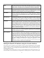
Setting the Switch's IP Address using the Console Interface ........................................................................................................... 28
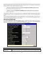
Advanced Settings.............................................................................................................................................................29
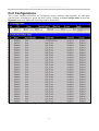
Port Configurations ...........................................................................................................................................................31
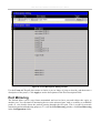
Port Description.................................................................................................................................................................32
Port Mirroring ...................................................................................................................................................................33
Link Aggregation ..............................................................................................................................................................34
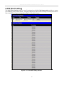
LACP Port Setting.............................................................................................................................................................38
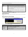
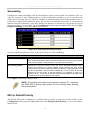
MAC Notification..............................................................................................................................................................39
MAC Notification Global Settings .................................................................................................................................................. 39
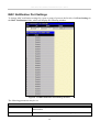
MAC Notification Port Settings....................................................................................................................................................... 40
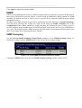
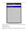
IGMP.................................................................................................................................................................................41
IGMP Snooping ............................................................................................................................................................................... 41
Static Router Ports Entry ................................................................................................................................................................. 43
Spanning Tree ...................................................................................................................................................................44
STP Bridge Global Settings............................................................................................................................................................. 46
MST Configuration Table................................................................................................................................................................ 49
MSTI Settings.................................................................................................................................................................................. 52
STP Instance Settings ...................................................................................................................................................................... 53
MSTP Port Information ................................................................................................................................................................... 54
Forwarding Filtering..........................................................................................................................................................56
Unicast Forwarding ......................................................................................................................................................................... 56
Static Multicast Forwarding............................................................................................................................................................. 56
Multicast Port Filtering Mode.......................................................................................................................................................... 58
VLANs ..............................................................................................................................................................................59
VLAN Description........................................................................................................................................................................... 59
IEEE 802.1Q VLANs ...................................................................................................................................................................... 60
Static VLAN Entry .......................................................................................................................................................................... 65
GVRP Setting .................................................................................................................................................................................. 68
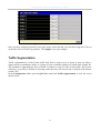
Traffic Control................................................................................................................................................................................. 69
Port Security .................................................................................................................................................................................... 70
QoS....................................................................................................................................................................................72
Port Bandwidth ................................................................................................................................................................................ 73
Scheduling ....................................................................................................................................................................................... 75
802.1p Default Priority .................................................................................................................................................................... 75
802.1p User Priority......................................................................................................................................................................... 76
Traffic Segmentation ....................................................................................................................................................................... 77
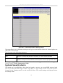
System Severity Alerts ......................................................................................................................................................78
System Log Server ............................................................................................................................................................79
SNTP Settings ...................................................................................................................................................................81
Time Settings................................................................................................................................................................................... 81
Time Zone and DST ........................................................................................................................................................................ 83
Access Profile Table..........................................................................................................................................................84
Configuring the Access Profile Table.............................................................................................................................................. 84
PAE Access Entity (802.1X).............................................................................................................................................98
802.1x Port-Based and MAC-Based Access Control....................................................................................................................... 98
Authentication Process .................................................................................................................................................................. 101
Port-Based Network Access Control ............................................................................................................................................. 101
MAC-Based Network Access Control ........................................................................................................................................... 103
Configure Authenticator ................................................................................................................................................................ 103
PAE System Control...................................................................................................................................................................... 106
RADIUS Server ............................................................................................................................................................................. 110
IP-MAC Binding .............................................................................................................................................................111
IP-MAC Binding Port.................................................................................................................................................................... 112
IP-MAC Binding Table ................................................................................................................................................................. 112
IP-MAC Binding Blocked ............................................................................................................................................................. 113
Limited IP Multicast Range Settings...............................................................................................................................114
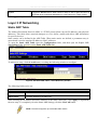
Layer 3 IP Networking ....................................................................................................................................................116
Static ARP Table ........................................................................................................................................................................... 116
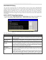
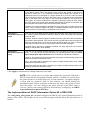
DHCP/BOOTP Relay .................................................................................................................................................................... 117
Management.........................................................................................................................................................................121
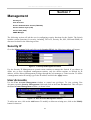
Security IP .......................................................................................................................................................................121
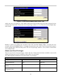
User Accounts .................................................................................................................................................................121
Access Authentication Control........................................................................................................................................123
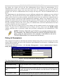
Policy & Parameters ...................................................................................................................................................................... 124
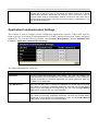
Application's Authentication Settings............................................................................................................................................ 125
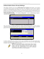
Authentication Server Group Settings ........................................................................................................................................... 126
Authentication Server Hosts .......................................................................................................................................................... 127
Login Method Lists........................................................................................................................................................................ 128
Enable Method Lists ...................................................................................................................................................................... 130
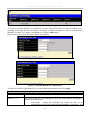
Local Enable Password.................................................................................................................................................................. 132
Enable Admin ................................................................................................................................................................................ 133
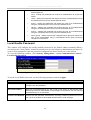
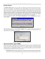
Secure Socket Layer (SSL) .............................................................................................................................................133
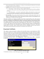
Download Certificate..................................................................................................................................................................... 134
Ciphersuite..................................................................................................................................................................................... 135
Secure Shell (SSH)..........................................................................................................................................................136
SSH Configuration......................................................................................................................................................................... 137
SSH Algorithm .............................................................................................................................................................................. 138
SSH User Authentication............................................................................................................................................................... 139
SNMP Manager...............................................................................................................................................................141
SNMP Settings .............................................................................................................................................................................. 141
SNMP User Table.......................................................................................................................................................................... 142
SNMP View Table......................................................................................................................................................................... 145
SNMP Group Table ....................................................................................................................................................................... 146
SNMP Community Table Configuration ....................................................................................................................................... 148
SNMP Host Table.......................................................................................................................................................................... 149
SNMP Engine ID........................................................................................................................................................................... 150
Monitoring ...........................................................................................................................................................................151
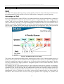
Port Utilization ................................................................................................................................................................151
CPU Utilization ...............................................................................................................................................................152
Packets.............................................................................................................................................................................153
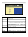
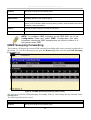
Received (RX) ............................................................................................................................................................................... 153
UMB Cast (RX)............................................................................................................................................................................. 156
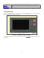
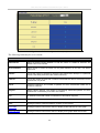
Transmitted (TX) ........................................................................................................................................................................... 157
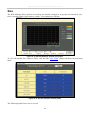
Errors...............................................................................................................................................................................159
Received (RX) ............................................................................................................................................................................... 159
Transmitted (TX) ........................................................................................................................................................................... 161
Size ..................................................................................................................................................................................163
MAC Address..................................................................................................................................................................164
Switch History.................................................................................................................................................................166
IGMP Snooping Group ...................................................................................................................................................167
IGMP Snooping Forwarding ...........................................................................................................................................168
VLAN Status ...................................................................................................................................................................169
Router Port ......................................................................................................................................................................169
Port Access Control.........................................................................................................................................................170
Authenticator State ........................................................................................................................................................................ 170
Layer 3 Feature................................................................................................................................................................173
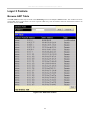
Browse ARP Table ........................................................................................................................................................................ 173
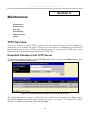
Maintenance .........................................................................................................................................................................174
TFTP Services .................................................................................................................................................................174
Download Firmware From TFTP Server ....................................................................................................................................... 174
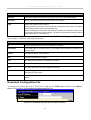
Download Configuration File ........................................................................................................................................................ 175
Upload Configuration .................................................................................................................................................................... 176
Upload Log.................................................................................................................................................................................... 176
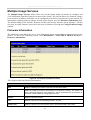
Multiple Image Services..................................................................................................................................................177
Firmware Information.................................................................................................................................................................... 177
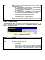
Config Firmware Image................................................................................................................................................................. 178
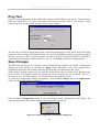
Ping Test..........................................................................................................................................................................179
Save Changes ..................................................................................................................................................................179
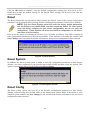
Reset ................................................................................................................................................................................180
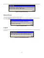
Reset System ...................................................................................................................................................................180
Reset Config....................................................................................................................................................................180
Reboot Device ............................................................................................................................................................................... 181
Logout ........................................................................................................................................................................................... 181
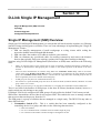
D-Link Single IP Management ............................................................................................................................................182
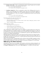
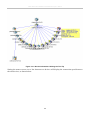
Single IP Management (SIM) Overview .........................................................................................................................182
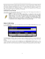
SIM Using The Web Interface ........................................................................................................................................183
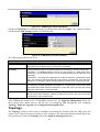
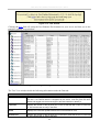
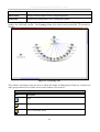
Topology .........................................................................................................................................................................184
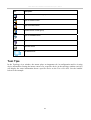
Tool Tips .........................................................................................................................................................................187
Right-Click .................................................................................................................................................................................... 189
Menu Bar ....................................................................................................................................................................................... 193
Firmware Upgrade...........................................................................................................................................................194
Configuration File Backup/Restore ............................................................................................................................................... 195
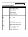
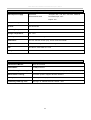
Technical Specifications ......................................................................................................................................................196
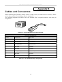
Cables and Connectors.........................................................................................................................................................198
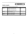
Cable Lengths ......................................................................................................................................................................199
Glossary ...............................................................................................................................................................................200
DES-3526 / DES-3526DC Fast Ethernet Layer 2 Switch
Preface
The DES-3526/DES-3526DC Manual is divided into sections that describe the system installation and
operating instructions with examples.
Section 1, Introduction - Describes the Switch and its features.
Section 2, Installation- Helps you get started with the basic installation of the Switch and also
describes the front panel, rear panel, side panels, and LED indicators of the Switch. Included in this
section is a description of how to hook up the DC power supply for the DES-3526DC.
Section 3, Connecting the Switch - Tells how you can connect the Switch to your Ethernet/Fast
Ethernet network.
Section 4, Introduction to Switch Management - Introduces basic Switch management features,
including password protection, SNMP settings, IP address assignment and connecting devices to the
Switch.
Section 5, Introduction to Web-based Switch Management - Talks about connecting to and using
the Web-based switch management feature on the Switch.
Section 6, Configuring the Switch - A detailed discussion about configuring some of the basic
functions of the Switch, including accessing the Switch information, using the Switch's utilities and
setting up network configurations, such as Quality of Service, The Access Profile Table, port
mirroring and configuring the Spanning Tree.
Section 7, Management - A discussion of the security features of the Switch, including Security IP,
User Accounts, Access Authentication Control, and SNMP.
Section 8, Monitoring - Features graphs and screens used in monitoring features and packets on the
Switch.
Section 9, Maintenance - Features information on Switch utility functions, including TFTP Services, Switch History, Ping Test Save Changes and Rebooting Services.
Section 10, Single IP Management - Discussion on the Single IP Management function of the
Switch, including functions and features of the Java based user interface and the utilities of the SIM
function.
Appendix A, Technical Specifications - The technical specifications of the DES-3526 and DES3526DC.
Appendix B, Cables and Connectors - Describes the RJ-45 receptacle/connector, straight through
and crossover cables and standard pin assignments.
Appendix C, Cable Lengths - Information on cable types and maximum distances.
Glossary - Lists definitions for terms and acronyms used in this document.
vi
DES-3526 / DES-3526DC Fast Ethernet Layer 2 Switch
Intended Readers
The DES-3526 / DES-3526DC Manual contains information for setup and management of the
Switch. This manual is intended for network managers familiar with network management concepts
and terminology.
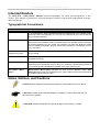
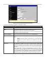
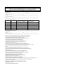
Typographical Conventions
Convention
Description
[]
In a command line, square brackets indicate an optional entry. For example: [copy
filename] means that optionally you can type copy followed by the name of the file.
Do not type the brackets.
Bold font
Indicates a button, a toolbar icon, menu, or menu item. For example: Open the File
menu and choose Cancel. Used for emphasis. May also indicate system messages
or prompts appearing on your screen. For example: You have mail. Bold font is also
used to represent filenames, program names and commands. For example: use the
copy command.
Boldface
Typewriter Font
Indicates commands and responses to prompts that must be typed exactly as printed
in the manual.
Initial capital letter
Indicates a window name. Names of keys on the keyboard have initial capitals. For
example: Click Enter.
Italics
Indicates a window name or a field. Also can indicate a variables or parameter that is
replaced with an appropriate word or string. For example: type filename means that
you should type the actual filename instead of the word shown in italic.
Menu Name > Menu
Option
Menu Name > Menu Option Indicates the menu structure. Device > Port > Port
Properties means the Port Properties menu option under the Port menu option that
is located under the Device menu.
Notes, Notices, and Cautions
A NOTE indicates important information that helps you make better use of your device.
A NOTICE indicates either potential damage to hardware or loss of data and tells you
how to avoid the problem.
A CAUTION indicates a potential for property damage, personal injury, or death.
vii
DES-3526 / DES-3526DC Fast Ethernet Layer 2 Switch
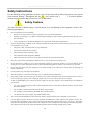
Safety Instructions
Use the following safety guidelines to ensure your own personal safety and to help protect your system
from potential damage. Throughout this document, the caution icon (
) is used to indicate
cautions and precautions that you need to review and follow.
Safety Cautions
To reduce the risk of bodily injury, electrical shock, fire, and damage to the equipment, observe the
following precautions.
•
Observe and follow service markings.
•
Do not service any product except as explained in your system documentation.
•
Opening or removing covers that are marked with the triangular symbol with a lightning bolt may expose you to
electrical shock.
•
•
Only a trained service technician should service components inside these compartments.
If any of the following conditions occur, unplug the product from the electrical outlet and replace the part or contact
your trained service provider:
•
The power cable, extension cable, or plug is damaged.
•
An object has fallen into the product.
•
The product has been exposed to water.
•
The product has been dropped or damaged.
•
The product does not operate correctly when you follow the operating instructions.
•
Keep your system away from radiators and heat sources. Also, do not block cooling vents.
•
Do not spill food or liquids on your system components, and never operate the product in a wet environment. If the
system gets wet, see the appropriate section in your troubleshooting guide or contact your trained service provider.
•
Do not push any objects into the openings of your system. Doing so can cause fire or electric shock by shorting out
interior components.
•
Use the product only with approved equipment.
•
Allow the product to cool before removing covers or touching internal components.
•
Operate the product only from the type of external power source indicated on the electrical ratings label. If you are
not sure of the type of power source required, consult your service provider or local power company.
•
To help avoid damaging your system, be sure the voltage on the power supply is set to match the power available at
your location:
•
115 volts (V)/60 hertz (Hz) in most of North and South America and some Far Eastern countries such as South
Korea and Taiwan
•
100 V/50 Hz in eastern Japan and 100 V/60 Hz in western Japan
•
230 V/50 Hz in most of Europe, the Middle East, and the Far East
•
–48 VDC for DC power supply unit on DES-3526DC only
•
Also, be sure that attached devices are electrically rated to operate with the power available in your location.
•
Use only approved power cable(s). If you have not been provided with a power cable for your system or for any ACpowered option intended for your system, purchase a power cable that is approved for use in your country. The power
cable must be rated for the product and for the voltage and current marked on the product's electrical ratings label.
The voltage and current rating of the cable should be greater than the ratings marked on the product.
viii
DES-3526 / DES-3526DC Fast Ethernet Layer 2 Switch
•
To help prevent electric shock, plug the system and peripheral power cables into properly grounded electrical outlets.
These cables are equipped with three-prong plugs to help ensure proper grounding. Do not use adapter plugs or
remove the grounding prong from a cable. If you must use an extension cable, use a 3-wire cable with properly
grounded plugs.
•
Observe extension cable and power strip ratings. Make sure that the total ampere rating of all products plugged into
the extension cable or power strip does not exceed 80 percent of the ampere ratings limit for the extension cable or
power strip.
•
To help protect your system from sudden, transient increases and decreases in electrical power, use a surge
suppressor, line conditioner, or uninterruptible power supply (UPS).
•
Position system cables and power cables carefully; route cables so that they cannot be stepped on or tripped over. Be
sure that nothing rests on any cables.
•
Do not modify power cables or plugs. Consult a licensed electrician or your power company for site modifications.
Always follow your local/national wiring rules.
•
When connecting or disconnecting power to hot-pluggable power supplies, if offered with your system, observe the
following guidelines:
•
•
Install the power supply before connecting the power cable to the power supply.
•
Unplug the power cable before removing the power supply.
•
If the system has multiple sources of power, disconnect power from the system by unplugging all power cables
from the power supplies.
Move products with care; ensure that all casters and/or stabilizers are firmly connected to the system. Avoid sudden
stops and uneven surfaces.
General Precautions for Rack-Mountable Products
Observe the following precautions for rack stability and safety. Also, refer to the rack installation
documentation accompanying the system and the rack for specific caution statements and procedures.
•
Systems are considered to be components in a rack. Thus, "component" refers to any system as well as to various
peripherals or supporting hardware.
•
Before working on the rack, make sure that the stabilizers are secured to the rack, extended to the floor, and that the
full weight of the rack rests on the floor. Install front and side stabilizers on a single rack or front stabilizers for joined
multiple racks before working on the rack.
•
Always load the rack from the bottom up, and load the heaviest item in the rack first.
•
Make sure that the rack is level and stable before extending a component from the rack.
•
Use caution when pressing the component rail release latches and sliding a component into or out of a rack; the slide
rails can pinch your fingers.
•
After a component is inserted into the rack, carefully extend the rail into a locking position, and then slide the
component into the rack.
•
Do not overload the AC supply branch circuit that provides power to the rack. The total rack load should not exceed
80 percent of the branch circuit rating.
•
Ensure that proper airflow is provided to components in the rack.
•
Do not step on or stand on any component when servicing other components in a rack.
ix
DES-3526 / DES-3526DC Fast Ethernet Layer 2 Switch
NOTE: A qualified electrician must perform all connections to DC power and
to safety grounds. All electrical wiring must comply with applicable local,
regional or national codes and practices.
CAUTION: Never defeat the ground conductor or operate the equipment in
the absence of a suitably installed ground conductor. Contact the
appropriate electrical inspection authority or an electrician if you are
uncertain that suitable grounding is available.
CAUTION: The system chassis must be positively grounded to the rack
cabinet frame. Do not attempt to connect power to the system until grounding
cables are connected. A qualified electrical inspector must inspect completed
power and safety ground wiring. An energy hazard will exist if the safety
ground cable is omitted or disconnected.
Protecting Against Electrostatic Discharge
Static electricity can harm delicate components inside your system. To prevent static damage, discharge static electricity from your body before you touch any of the electronic components, such as
the microprocessor. You can do so by periodically touching an unpainted metal surface on the chassis.
You can also take the following steps to prevent damage from electrostatic discharge (ESD):
1. When unpacking a static-sensitive component from its shipping carton, do not remove the
component from the antistatic packing material until you are ready to install the component in
your system. Just before unwrapping the antistatic packaging, be sure to discharge static
electricity from your body.
2. When transporting a sensitive component, first place it in an antistatic container or packaging.
3. Handle all sensitive components in a static-safe area. If possible, use antistatic floor pads,
workbench pads and an antistatic grounding strap.
x
DES-3526 / DES-3526DC Fast Ethernet Layer 2 Switch
Section 1
Introduction
Gigabit Ethernet Technology
Switch Description
Features
Ports
Front-Panel Components
Side Panel Description
Rear Panel Description
Gigabit Combo Ports
Gigabit Ethernet Technology
Gigabit Ethernet is an extension of IEEE 802.3 Ethernet utilizing the same packet structure, format,
and support for CSMA/CD protocol, full duplex, flow control, and management objects, but with a
tenfold increase in theoretical throughput over 100Mbps Fast Ethernet and a one hundred-fold increase
over 10Mbps Ethernet. Since it is compatible with all 10Mbps and 100Mbps Ethernet environments,
Gigabit Ethernet provides a straightforward upgrade without wasting a company's existing investment
in hardware, software, and trained personnel.
The increased speed and extra bandwidth offered by Gigabit Ethernet are essential to coping with the
network bottlenecks that frequently develop as computers and their busses get faster and more users
using applications that generate more traffic. Upgrading key components, such as your backbone and
servers to Gigabit Ethernet can greatly improve network response times as well as significantly speed
up the traffic between your sub networks.
Gigabit Ethernet enables fast optical fiber connections to support video conferencing, complex
imaging, and similar data-intensive applications. Likewise, since data transfers occur 10 times faster
than Fast Ethernet, servers outfitted with Gigabit Ethernet NIC's are able to perform 10 times the
number of operations in the same amount of time.
In addition, the phenomenal bandwidth delivered by Gigabit Ethernet is the most cost-effective
method to take advantage of today and tomorrow's rapidly improving switching and routing internetworking technologies.
Switch Description
The DES-3526 is equipped with unshielded twisted-pair (UTP) cable ports providing dedicated 10 or
100 Mbps bandwidth. The Switch has 24 UTP ports and Auto MDI-X/MDI-II convertible ports that
can be used for unlinking to another switch. These ports can be used for connecting PCs, printers,
servers, hubs, routers, switches and other networking devices. The dual speed ports use standard
twisted-pair cabling and are ideal for segmenting networks into small, connected sub networks for
superior performance. Each 10/100 port can support up to 200 Mbps of throughput in full-duplex
mode.
In addition, the Switch has 2 Mini-GBIC combo ports. These two-gigabit combo ports are ideal for
connecting to a server or network backbone.
1
DES-3526 / DES-3526DC Fast Ethernet Layer 2 Switch
This stand-alone Switch enables the network to use some of the most demanding multimedia and
imaging applications concurrently with other user applications without creating bottlenecks. The builtin console interface can be used to configure the Switch's settings for priority queuing, VLANs, and
port trunk groups, port monitoring, and port speed.
NOTE: For the remainder of this manual both hardware versions of the Switch,
the DES-3526 and DES-3526DC will be referred to as simply the Switch or the
DES-3526 except where the differences are relevant.
Features
•
IEEE 802.3 10BASE-T compliant
•
IEEE 802.3u 100BASE-TX compliant
•
IEEE 802.1p Priority Queues
•
IEEE 802.3x flow control in full duplex mode
•
IEEE 802.3ad Link Aggregation Control
Protocol support.
•
IEEE 802.1x Port-based and MAC-based
Access Control
•
Address table: Supports up to 8K MAC
addresses per device
•
Supports a packet buffer of up to 3 Mbits
•
Supports Port-based VLAN Groups
•
Port Trunking with flexible load distribution
and fail-over function
•
IGMP Snooping support
•
SNMP support
•
IEEE 802.1Q VLAN
•
•
IEEE 802.1D Spanning Tree, IEEE 802.1W
Rapid Spanning Tree and IEEE 802.1s
Multiple Spanning Tree support
Secure Sockets Layer (SSL) and Secure Shell
(SSH) support
•
Port Mirroring support
•
MIB support for:
•
RFC1213 MIB II
•
RFC1493 Bridge
•
RFC1757 RMON
•
RFC1643 Ether-like MIB
•
RFC2233 Interface MIB
•
Private MIB
•
RFC2674 for 802.1p
•
IEEE 802.1x MIB
•
RS-232 DCE console port for Switch
management
•
Provides parallel LED display for port status
such as link/act, speed, etc.
•
Access Control List (ACL) support
•
Single IP Management support
•
Access Authentication Control utilizing
TACACS, XTACACS and TACACS+
•
Dual Image Firmware
•
Simple Network Time Protocol support
•
MAC Notification support
•
Asymmetric VLAN support
•
System and Port Utilization support
•
System Log Support
•
Support port-based enable and disable
•
High performance switching engine performs forwarding and filtering at full wire speed, maximum 14, 881
packets/sec on each 10Mbps Ethernet port, and maximum 148,810 packet/sec on 100Mbps Fast Ethernet port.
•
Full- and half-duplex for both 10Mbps and 100Mbps connections. Full duplex allows the switch port to
simultaneously transmit and receive data. It only works with connections to full-duplex-capable end stations and
switches. Connections to a hub must take place at half-duplex
•
Support broadcast storm filtering
•
Non-blocking store and forward switching scheme capability to support rate adaptation and protocol conversion
•
Supports by-port Egress/Ingress rate control.
2
DES-3526 / DES-3526DC Fast Ethernet Layer 2 Switch
•
Efficient self-learning and address recognition mechanism enables forwarding rate at wire speed
2
DES-3526 / DES-3526DC Fast Ethernet Layer 2 Switch
Ports
•
Twenty-four high-performance (MDI-X/MDI-II) ports for connecting to end stations, servers, hubs and other
networking devices.
•
All UTP ports can auto-negotiate between 10Mbps and 100Mbps, half-duplex and full duplex, and feature flow
control.
•
Two 1000BASE-T Mini-GBIC combo ports for connecting to another switch, server, or network backbone.
•
RS-232 DCE Diagnostic port (console port) for setting up and managing the Switch via a connection to a
console terminal or PC using a terminal emulation program.
NOTE: For customers interested in D-View, D-Link Corporation's
proprietary SNMP management software, go to the D-Link Website
(www.dlink.com.cn) and download the software and manual.
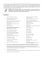
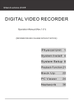
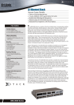
Front-Panel Components
The front panel of the Switch consists of LED indicators for power and for each 10/100 Mbps twistedpair ports, and two 1000BASE-T Mini-GBIC ports. The ports of the DES-3526 and DES-3526DC are
identical.
Figure 1- 1. Front Panel View of the DES-3526
The DES-3526DC does not support a redundant power supply; therefore the RPS indicator does not
appear on the front panel.
Figure 1- 2. Front Panel View of DES-3526DC
Comprehensive LED indicators display the status of the Switch and the network.
3
DES-3526 / DES-3526DC Fast Ethernet Layer 2 Switch
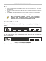
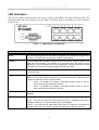
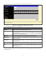
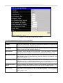
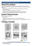
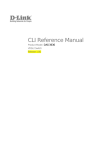
LED Indicators
The Switch supports LED indicators for Power, Console, RPS (DES-3526 only) and Port LEDs. The
following shows the LED indicators for the DES-3526 along with an explanation of each indicator.
LEDs for the
Figure 1- 3. LED Indicators on DES-3526
LED
Description
Power
This LED will light green after the Switch is powered on to indicate the ready state of
the device. The indicator is dark when the Switch is powered off.
Console
This LED should blink during the Power-On Self Test (POST). When the POST is finished, the LED goes dark. This indicator is lit sold green when the Switch is being
logged into via out-of-band/local console management through the RS-232 console
port in the back of the Switch using a straight-through serial cable.
RPS (DES-3526 only)
This LED will be lit when the redundant power supply is present and in use. Otherwise
it will remain dark.
Port LEDs
One row of LEDs for each port is located above the ports on the front panel. The first
LED is for the top port and the second one is for the bottom ports. These port LEDs
will light two different colors for 10M and 100M.
•
Amber - For speeds of 10 Mbps. A solid light denotes activity on the port
while a blinking light indicates a valid link.
•
Green - For speeds of 100 Mbps. A solid light denotes activity on the port
while a blinking light indicates a valid link.
100M/10M
These LEDs will light steady green to indicate that the port is transferring data at
100Mbps.
Gigabit Ports
The Switch's two Mini GBIC ports have their own corresponding LEDs:
Speed - This LED will light solid green when the port is transferring at a rate of
1000Mbps. When dark, the port is transferring at 10/100Mbps.
Link/Act - This LED will light solid green when there is a valid link. A blinking LED
indicates current activity on the port. A dark LED indicates no activity on the port.
4
DES-3526 / DES-3526DC Fast Ethernet Layer 2 Switch
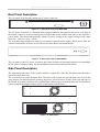
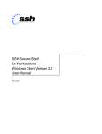
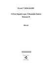
Rear Panel Description
The rear panel of the Switch contains an AC power connector.
Figure 1- 4. Rear panel view of the DES-3526
The AC power connector is a standard three-pronged connector that supports the power cord. Plug-in
the female connector of the provided power cord into this socket, and the male side of the cord into a
power outlet. The Switch automatically adjusts its power setting to any supply voltage in the range
from 100 ~ 240 VAC at 50 ~ 60 Hz.
The rear panel also includes an outlet for an optional external power supply. When power fails, the
optional external RPS will take over all the power immediately and automatically.
Figure 1- 5. Rear panel view of DES-3526DC
The rear panel of the DC power version of the Switch includes an opening designed to accommodate
the DC power wiring assembly. See the installation instructions in Section for details.
Side Panel Description
The right-hand side panel of the Switch contains a system fan, while the left hand panel includes a
system fan and a heat vent.
The system fans are used to dissipate heat. The sides of the system also provide heat vents to serve the
same purpose. Do not block these openings, and leave at least 6 inches of space at the rear and sides of
the Switch for proper ventilation. Be reminded that without proper heat dissipation and air circulation,
system components might overheat, which could lead to system failure.
Figure 1- 6. Side Panels
5
DES-3526 / DES-3526DC Fast Ethernet Layer 2 Switch
6
DES-3526 / DES-3526DC Fast Ethernet Layer 2 Switch
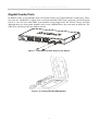
Gigabit Combo Ports
In addition to the 24 10/100 Mbps ports, the Switch features two Gigabit Ethernet Combo ports. These
two ports are 1000BASE-T copper ports (provided) and Mini-GBIC ports (optional). See the diagram
below to view the two Mini-GBIC port modules being plugged into the Switch. Please note that
although these two front panel modules can be used simultaneously, the ports must be different. The
GBIC port will always have the highest priority.
Figure 1- 7. Mini-GBIC modules plug-in to the Switch
Figure 1- 8. Installing the Mini-GBIC Module
7
DES-3526 / DES-3526DC Fast Ethernet Layer 2 Switch
SECTION 2
Installation
Package Contents
Before You Connect to the Network
Installing the Switch Without the Rack
Rack Installation
Power On
Package Contents
Open the shipping carton of the Switch and carefully unpack its contents. The carton should contain
the following items:
•
One DES-3526 Stand-alone Switch
•
One AC power cord
•
This Manual
•
Registration card
•
Mounting kit (two brackets and screws)
•
Four rubber feet with adhesive backing
•
RS-232 console cable
If any item is found missing or damaged, please contact your local D-Link Reseller for replacement.
Before You Connect to the Network
The site where you install the Switch may greatly affect its performance. Please follow these
guidelines for setting up the Switch.
•
Install the Switch on a sturdy, level surface that can support at least 6.6 lb. (3 kg) of weight. Do not place heavy
objects on the Switch.
•
The power outlet should be within 1.82 meters (6 feet) of the Switch.
•
Visually inspect the power cord and see that it is fully secured to the AC power port.
•
Make sure that there is proper heat dissipation from and adequate ventilation around the Switch. Leave at least
10 cm (4 inches) of space at the front and rear of the Switch for ventilation.
•
Install the Switch in a fairly cool and dry place for the acceptable temperature and humidity operating ranges.
•
Install the Switch in a site free from strong electromagnetic field generators (such as motors), vibration, dust,
and direct exposure to sunlight.
•
When installing the Switch on a level surface, attach the rubber feet to the bottom of the device. The rubber feet
cushion the Switch, protect the casing from scratches and prevent it from scratching other surfaces.
8
DES-3526 / DES-3526DC Fast Ethernet Layer 2 Switch
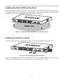
Installing the Switch Without the Rack
When installing the Switch on a desktop or shelf, the rubber feet included with the Switch should first
be attached. Attach these cushioning feet on the bottom at each corner of the device. Allow enough
ventilation space between the Switch and any other objects in the vicinity.
Figure 2- 1. Prepare Switch for installation on a desktop or shelf
Installing the Switch in a Rack
The Switch can be mounted in a standard 19" rack. Use the following diagrams to guide you.
Figure 2- 2. Fasten mounting brackets to Switch
Fasten the mounting brackets to the Switch using the screws provided. With the brackets attached
securely, you can mount the Switch in a standard rack as shown in Figure 2-3 below.
9
DES-3526 / DES-3526DC Fast Ethernet Layer 2 Switch
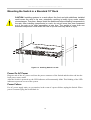
Mounting the Switch in a Standard 19" Rack
CAUTION: Installing systems in a rack without the front and side stabilizers installed
could cause the rack to tip over, potentially resulting in bodily injury under certain
circumstances. Therefore, always install the stabilizers before installing components in
the rack. After installing components in a rack, do not pull more than one component
out of the rack on its slide assemblies at one time. The weight of more than one
extended component could cause the rack to tip over and may result in injury.
Figure 2- 3. Installing Switch in a rack
Power On AC Power
Plug one end of the AC power cord into the power connector of the Switch and the other end into the
local power source outlet.
After the Switch is powered on, the LED indicators will momentarily blink. This blinking of the LED
indicators represents a reset of the system.
Power Failure
For AC power supply units, as a precaution, in the event of a power failure, unplug the Switch. When
power is resumed, plug the Switch back in.
10
DES-3526 / DES-3526DC Fast Ethernet Layer 2 Switch
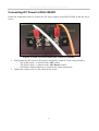
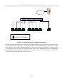
Connecting DC Power to DES-3526DC
Follow the instructions below to connect the DC power supply of the DES-3526DC to the DC power
source.
Figure 2- 4. Power connections attached to contacts on assembly
1. Firmly attach the DC power to the negative and positive contacts on the wiring assembly.
•
The negative pole (-) connects to the -48V contact.
•
The positive pole (+) connects to the -48V Return contact.
•
If available, earth ground may be connected to center contact post.
2. Tighten the contact screws so the connection is secure.
11
DES-3526 / DES-3526DC Fast Ethernet Layer 2 Switch
Section 3
Connecting The Switch
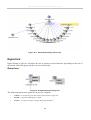
Switch To End Node
Switch To Hub or Switch
Connecting To Network Backbone or Server
NOTE: All 24 high-performance NWay Ethernet ports can
support both MDI-II and MDI-X connections.
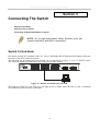
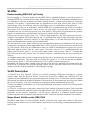
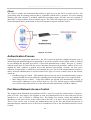
Switch To End Node
End nodes include PCs outfitted with a 10, 100 or 1000 Mbps RJ?45 Ethernet/Fast Ethernet Network
Interface Card (NIC) and most routers.
An end node can be connected to the Switch via a twisted-pair Category 3, 4, or 5 UTP/STP cable.
The end node should be connected to any of the ports of the Switch.
Figure 3- 1. Switch connected to an end node
The Link/Act LEDs for each UTP port will light green or amber when the link is valid. A blinking
LED indicates packet activity on that port.
12
DES-3526 / DES-3526DC Fast Ethernet Layer 2 Switch
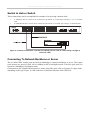
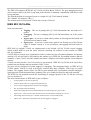
Switch to Hub or Switch
These connections can be accomplished in a number of ways using a normal cable.
•
A 10BASE-T hub or switch can be connected to the Switch via a twisted-pair Category 3, 4 or 5 UTP/STP
cable.
•
A 100BASE-TX hub or switch can be connected to the Switch via a twisted -pair Category 5 UTP/STP cable.
Figure 3- 2. Switch connected to a normal (non-Uplink) port on a hub or switch using a straight or
crossover cable
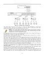
Connecting To Network Backbone or Server
The two Mini-GBIC combo ports are ideal for unlinking to a network backbone or server. The copper
ports operate at a speed of 1000, 100 or 10Mbps in full or half duplex mode. The fiber optic ports can
operate at 1000Mbps in full duplex mode.
Connections to the Gigabit Ethernet ports are made using fiber optic cable or Category 5 copper cable,
depending on the type of port. A valid connection is indicated when the Link LED is lit.
13
DES-3526 / DES-3526DC Fast Ethernet Layer 2 Switch
Section 4
Introduction To Switch Management
Management Options
Web-based Management Interface
SNMP-Based Management
Managing User Accounts
Command Line Console Interface Through The Serial Port
Connecting the Console Port (RS-232 DCE)
First Time Connecting to The Switch
Password Protection
SNMP Settings
IP Address Assignment
Connecting Devices to the Switch
Management Options
This system may be managed out-of-band through the console port on the front panel or in-band using
Telnet. The user may also choose the web-based management, accessible through a web browser.
Web-based Management Interface
After you have successfully installed the Switch, you can configure the Switch, monitor the LED
panel, and display statistics graphically using a web browser, such as Netscape Navigator (version 6.2
and higher) or Microsoft® Internet Explorer (version 5.0).
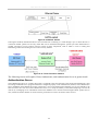
SNMP-Based Management
You can manage the Switch with an SNMP-compatible console program. The Switch supports SNMP
version 1.0, version 2.0 and version 3.0. The SNMP agent decodes the incoming SNMP messages and
responds to requests with MIB objects stored in the database. The SNMP agent updates the MIB
objects to generate statistics and counters.
Connecting the Console Port (RS-232 DCE)
The Switch provides an RS-232 serial port that enables a connection to a computer or terminal for
monitoring and configuring the Switch. This port is a female DB-9 connector, implemented as a data
terminal equipment (DTE) connection.
To use the console port, you need the following equipment:
•
A terminal or a computer with both a serial port and the ability to emulate a terminal.
•
A null modem or crossover RS-232 cable with a female DB-9 connector for the console port on the Switch.
14
DES-3526 / DES-3526DC Fast Ethernet Layer 2 Switch
To connect a terminal to the console port:
1. Connect the female connector of the RS-232 cable directly to the console port on the Switch,
and tighten the captive retaining screws.
2. Connect the other end of the cable to a terminal or to the serial connector of a computer
running terminal emulation software. Set the terminal emulation software as follows:
3. Select the appropriate serial port (COM port 1 or COM port 2).
4. Set the data rate to 9600 baud.
5. Set the data format to 8 data bits, 1 stop bit, and no parity.
6. Set flow control to none.
7. Under Properties, select VT100 for Emulation mode.
8. Select Terminal keys for Function, Arrow, and Ctrl keys. Ensure that you select Terminal keys
(not Windows keys).
NOTE: When you use HyperTerminal with the Microsoft® Windows® 2000
operating system, ensure that you have Windows 2000 Service Pack 2 or
later installed. Windows 2000 Service Pack 2 allows you to use arrow keys
in HyperTerminal's VT100 emulation. See www.microsoft.com for
information on Windows 2000 service packs.
9. After you have correctly set up the terminal, plug the power cable into the power receptacle on
the back of the Switch. The boot sequence appears in the terminal.
10. After the boot sequence completes, the console login screen displays.
11. If you have not logged into the command line interface (CLI) program, press the Enter key at
the User name and password prompts. There is no default user name and password for the
Switch. The administrator must first create user names and passwords. If you have previously
set up user accounts, log in and continue to configure the Switch.
12. Enter the commands to complete your desired tasks. Many commands require administratorlevel access privileges. Read the next section for more information on setting up user accounts.
See the DES-3526 Command Line Interface Reference Manual on the documentation CD for
a list of all commands and additional information on using the CLI.
13. When you have completed your tasks, exit the session with the logout command or close the
emulator program.
15
DES-3526 / DES-3526DC Fast Ethernet Layer 2 Switch
Make sure the terminal or PC you are using to make this connection is configured to match these
settings.
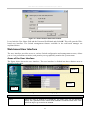
If you are having problems making this connection on a PC, make sure the emulation is set to VT-100.
You will be able to set the emulation by clicking on the File menu in you HyperTerminal window,
clicking on Properties in the drop-down menu, and then clicking the Settings tab. This is where you
will find the Emulation options. If you still do not see anything, try rebooting the Switch by
disconnecting its power supply.
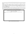
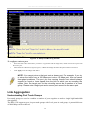
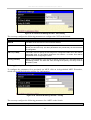
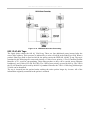
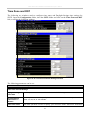
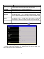
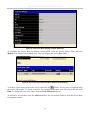
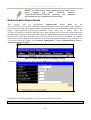
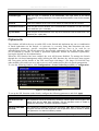
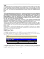
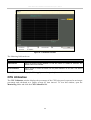
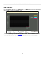
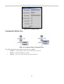
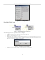
Once connected to the console, the screen below will appear on your console screen. This is where the
user will enter commands to perform all the available management functions. The Switch will prompt
the user to enter a user name and a password. Upon the initial connection, there is no user name or
password and therefore just press enter twice to access the command line interface.
Figure 4- 1. Initial screen after first connection
16
DES-3526 / DES-3526DC Fast Ethernet Layer 2 Switch
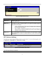
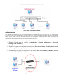
First Time Connecting to The Switch
The Switch supports user-based security that can allow you to prevent unauthorized users from
accessing the Switch or changing its settings. This section tells how to log onto the Switch.
NOTE: The passwords used to access the Switch are case-sensitive;
therefore, "S" is not the same as "s."
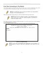
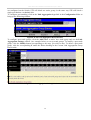
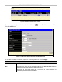
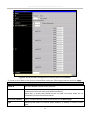
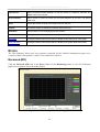
When you first connect to the Switch, you will be presented with the first login screen.
NOTE: Press Ctrl+R to refresh the screen. This command can be
used at any time to force the console program in the Switch to
refresh the console screen.
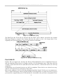
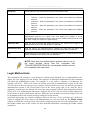
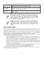
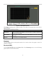
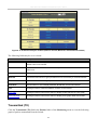
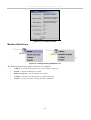
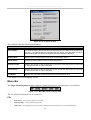
Press Enter in both the Username and Password fields. You will be given access to the command
prompt DES-3526:4# shown below:
There is no initial username or password. Leave the Username and Password fields blank.
Figure 4- 2. Command Prompt
NOTE: The first user automatically gets Administrator level privileges. It is
recommended to create at least one Admin-level user account for the
Switch.
17
DES-3526 / DES-3526DC Fast Ethernet Layer 2 Switch
Password Protection
The DES-3526 does not have a default user name and password. One of the first tasks when settings
up the Switch is to create user accounts. If you log in using a predefined administrator-level user
name, you have privileged access to the Switch's management software.
After your initial login, define new passwords for both default user names to prevent unauthorized
access to the Switch, and record the passwords for future reference.
To create an administrator-level account for the Switch, do the following:
•
At the CLI login prompt, enter create account admin followed by the <user name> and press the Enter key.
•
You will be asked to provide a password. Type the <password> used for the administrator account being
created and press the Enter key.
•
You will be prompted to enter the same password again to verify it. Type the same password and press the Enter
key.
•
Successful creation of the new administrator account will be verified by a Success message.
NOTE: Passwords are case sensitive. User names and
passwords can be up to 15 characters in length.
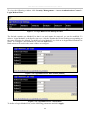
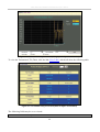
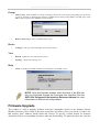
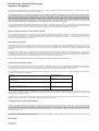
The sample below illustrates a successful creation of a new administrator-level account with the user
name "newmanager".
DES-3526:4#create account admin newmanager
Command: create account admin newmanager
Enter a case-sensitive new password:********
Enter the new password again for confirmation:********
Success.
DES-3526:4#
NOTICE: CLI configuration commands only modify the running
configuration file and are not saved when the Switch is rebooted.
To save all your configuration changes in nonvolatile storage, you
must use the save command to copy the running configuration file
to the startup configuration.
18
DES-3526 / DES-3526DC Fast Ethernet Layer 2 Switch
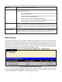
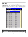
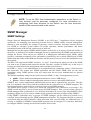
SNMP Settings
Simple Network Management Protocol (SNMP) is an OSI Layer 7 (Application Layer) designed
specifically for managing and monitoring network devices. SNMP enables network management
stations to read and modify the settings of gateways, routers, switches, and other network devices. Use
SNMP to configure system features for proper operation, monitor performance and detect potential
problems in the Switch, switch group or network.
Managed devices that support SNMP include software (referred to as an agent), which runs locally on
the device. A defined set of variables (managed objects) is maintained by the SNMP agent and used to
manage the device. These objects are defined in a Management Information Base (MIB), which
provides a standard presentation of the information controlled by the on-board SNMP agent. SNMP
defines both the format of the MIB specifications and the protocol used to access this information over
the network.
The DES-3526 supports SNMP versions 1, 2c, and 3. You can specify which version of SNMP you
want to use to monitor and control the Switch. The three versions of SNMP vary in the level of
security provided between the management station and the network device.
In SNMP v.1 and v.2, user authentication is accomplished using 'community strings', which function
like passwords. The remote user SNMP application and the Switch SNMP must use the same
community string. SNMP packets from any station that has not been authenticated are ignored
(dropped).
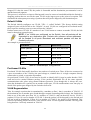
The default community strings for the Switch used for SNMP v.1 and v.2 management access are:
•
public - Allows authorized management stations to retrieve MIB objects.
•
private - Allows authorized management stations to retrieve and modify MIB objects.
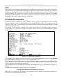
SNMP v.3 uses a more sophisticated authentication process that is separated into two parts. The first
part is to maintain a list of users and their attributes that are allowed to act as SNMP managers. The
second part describes what each user on that list can do as an SNMP manager.
The Switch allows groups of users to be listed and configured with a shared set of privileges. The
SNMP version may also be set for a listed group of SNMP managers. Thus, you may create a group of
SNMP managers that are allowed to view read-only information or receive traps using SNMP v.1
while assigning a higher level of security to another group, granting read/write privileges using SNMP
v.3.
Using SNMP v.3 individual users or groups of SNMP managers can be allowed to perform or be
restricted from performing specific SNMP management functions. The functions allowed or restricted
are defined using the Object Identifier (OID) associated with a specific MIB. An additional layer of
security is available for SNMP v.3 in that SNMP messages may be encrypted. To read more about
how to configure SNMP v.3 settings for the Switch read the section entitled Management.
Traps
Traps are messages that alert network personnel of events that occur on the Switch. The events can be
as serious as a reboot (someone accidentally turned OFF the Switch), or less serious like a port status
change. The Switch generates traps and sends them to the trap recipient (or network manager). Typical
traps include trap messages for Authentication Failure, Topology Change and Broadcast\Multicast
Storm.
19
DES-3526 / DES-3526DC Fast Ethernet Layer 2 Switch
MIBs
The Switch in the Management Information Base (MIB) stores management and counter information.
The Switch uses the standard MIB-II Management Information Base module. Consequently, values for
MIB objects can be retrieved from any SNMP-based network management software. In addition to the
standard MIB-II, the Switch also supports its own proprietary enterprise MIB as an extended
Management Information Base. Specifying the MIB Object Identifier may also retrieve the proprietary
MIB. MIB values can be either read-only or read-write.
IP Address Assignment
Each Switch must be assigned its own IP Address, which is used for communication with an SNMP
network manager or other TCP/IP application (for example BOOTP, TFTP). The Switch's default IP
address is 10.90.90.90. You can change the default Switch IP address to meet the specification of your
networking address scheme.
The Switch is also assigned a unique MAC address by the factory. This MAC address cannot be
changed, and can be found by entering the command "show switch" into the command line interface,
as shown below.
Figure 4- 3. Show switch command
The Switch's MAC address can also be found from the Web management program on the Switch
Information (Basic Settings) window on the Configuration menu.
The IP address for the Switch must be set before it can be managed with the Web-based manager. The
Switch IP address can be automatically set using BOOTP or DHCP protocols, in which case the actual
address assigned to the Switch must be known.
The IP address may be set using the Command Line Interface (CLI) over the console serial port as
follows:
Starting at the command line prompt, enter the commands
config ipif System ipaddress xxx.xxx.xxx.xxx/yyy.yyy.yyy.yyy
Where the x's represent the IP address to be assigned to the IP interface named System and the y's
represent the corresponding subnet mask.
20
DES-3526 / DES-3526DC Fast Ethernet Layer 2 Switch
Alternatively, you can enter config ipif System ipaddress xxx.xxx.xxx.xxx/z. Where the x's represent
the IP address to be assigned to the IP interface named System and the z represents the corresponding
number of subnets in CIDR notation.
The IP interface named System on the Switch can be assigned an IP address and subnet mask, and
then be used to connect a management station to the Switch's Telnet or Web-based management agent.
Figure 4- 4. Assigning the Switch an IP Address
In the above example, the Switch was assigned an IP address of 10.41.44.254 with a subnet mask of
255.0.0.0. The system message Success indicates that the command was executed successfully. The
Switch can now be configured and managed via Telnet and the CLI or via the Web-based
management.
Connecting Devices to the Switch
After you assign IP addresses to the Switch, you can connect devices to the Switch.
To connect a device to an SFP transceiver port:
•
Use your cabling requirements to select an appropriate SFP transceiver type.
•
Insert the SFP transceiver (sold separately) into the SFP transceiver slot.
•
Use the appropriate network cabling to connect a device to the connectors on the SFP transceiver.
NOTICE: When the SFP transceiver acquires a link, the
associated integrated 10/100/1000BASE-T port is disabled.
21
DES-3526 / DES-3526DC Fast Ethernet Layer 2 Switch
Section 5
Web-based Switch Configuration
Introduction
Login To Web manager
Web-Based User Interface
Basic Setup
Reboot
Basic Switch Setup
Network Management
Switch Utilities
Network Monitoring
IGMP Snooping Status
Introduction
All software functions of the DES-3526 can be managed, configured and monitored via the embedded
web-based (HTML) interface. The Switch can be managed from remote stations anywhere on the
network through a standard browser such as Opera, Netscape Navigator/Communicator, or Microsoft
Internet Explorer. The browser acts as a universal access tool and can communicate directly with the
Switch using the HTTP protocol.
The Web-based management module and the Console program (and Telnet) are different ways to
access the same internal switching software and configure it. Thus, all settings encountered in webbased management are the same as those found in the console program.
Login to Web Manager
To begin managing your Switch, simply run the browser you have installed on your computer and
point it to the IP address you have defined for the device. The URL in the address bar should read
something like: http://123.123.123.123, where the numbers 123 represent the IP address of the Switch.
NOTE: The Factory default IP address for the Switch is
10.90.90.90.
In the page that opens, click on the Login to make a setup button:
Figure 5- 1. Login hyperlink
This opens the management module's user authentication window, as seen below.
22
DES-3526 / DES-3526DC Fast Ethernet Layer 2 Switch
Figure 5- 2. Enter Network Password window
Leave both the User Name field and the Password field blank and click OK. This will open the Webbased user interface. The Switch management features available in the web-based manager are
explained below.
Web-based User Interface
The user interface provides access to various Switch configuration and management screens, allows
you to view performance statistics, and permits you to graphically monitor the system status.
Areas of the User Interface
The figure below shows the user interface. The user interface is divided into three distinct areas as
described in the table.
Area 2
Area 3
Area 1
Figure 5- 3. Main Web-Manager page
Area
Area 1
Function
Select the menu or window to be displayed. The folder icons can be opened to
display the hyperlinked menu buttons and subfolders contained within them. Click
the D-Link logo to go to the D-Link website.
23
DES-3526 / DES-3526DC Fast Ethernet Layer 2 Switch
Area 2
Presents a graphical near real-time image of the front panel of the Switch. This area
displays the Switch's ports and expansion modules, showing port activity, duplex
mode, or flow control, depending on the specified mode.
Various areas of the graphic can be selected for performing management functions,
including port configuration.
Area 3
Presents switch information based on your selection and the entry of configuration
data.
NOTICE: Any changes made to the Switch configuration
during the current session must be saved in the Save
Changes web menu (explained below) or use the command
line interface (CLI) command save.
Web Pages
When you connect to the management mode of the Switch with a web browser, a login window is
displayed. Enter a user name and password to access the Switch's management mode.
Below is a list and description of the main folders available in the web interface:
Configurations – Contains windows concerning configurations for IP Address, Switch Information,
Advanced Settings, Port Configuration, IGMP, Spanning Tree, Forwarding Filtering, VLANs, Port
Bandwidth, SNTP Settings, Port Security, QoS, MAC Notification, LACP, Access Profile Table,
System Log Servers, PAE Access Entity, and Layer 3 IP Networking.
Security Management – Contains windows concerning configurations for Security IP, User
Accounts, Access Authentication Control (TACACS), Secure Sockets Layer (SSL), Secure Shell
(SSH), and SNMP V3.
Monitoring – Contains windows concerning monitoring the Switch, pertaining to Port Utilization,
CPU Utilization, Packets, Errors Size, MAC Address, IGMP Snooping Group, IGMP Snooping
Forwarding, VLAN Status, Router Port, Port Access Control and Layer 3 Feature.
Maintenance – Contains windows concerning configurations and information about Switch maintenance, including TFTP Services, Switch History, Ping Test, Save Changes, Reboot Services, and
Logout.
Single IP Management – Contains windows concerning information on Single IP Management,
including SIM Settings, Topology, and Firmware/Configuration downloads.
NOTE: Be sure to configure the user name and password in
the User Accounts menu before connecting the Switch to the
greater network.
24
DES-3526 / DES-3526DC Fast Ethernet Layer 2 Switch
Section 6
Configuring the Switch
Switch Information
IP Address
Advanced Settings
Port Configuration
Port Description
Port Mirroring
Link Aggregation
LACP Port Setting
MAC Notification
IGMP
Spanning Tree
Forward Filtering
VLANs
Port Security
QoS
System Log Servers
SNTP Settings
Access Profile Table
PAE Access Entity
Layer 3 IP Networking
Switch Information
The subsections below describe how to change some of the basic settings for the Switch such as
changing IP settings and assigning user names and passwords for management access privileges, as
well as how to save the changes and restart the Switch.
Click the Switch Information link in the Configuration menu.
25
DES-3526 / DES-3526DC Fast Ethernet Layer 2 Switch
Figure 6- 1. Switch Information (Basic Settings) window
The Switch Information (Basic Settings) window shows the Switch's MAC Address (assigned by the
factory and unchangeable), the Boot PROM, Firmware Version, and Hardware Version. This
information is helpful to keep track of PROM and firmware updates and to obtain the Switch's MAC
address for entry into another network device's address table, if necessary. The user may also enter a
System Name, System Location and System Contact to aid in defining the Switch, to the user's preference.
IP Address
The IP Address may initially be set using the console interface prior to connecting to it through the
Ethernet. If the Switch IP address has not yet been changed, read the introduction of the DES-3526
Command Line Interface Manual or return to Section 4 of this manual for more information.
To change IP settings using the web manager you must access the IP Address menu located in the
Configuration folder.
To configure the Switch's IP address:
Open the Configuration folder and click the IP Address menu link. The web manager will display
the Switch's current IP settings in the IP configuration menu, as seen below.
26
DES-3526 / DES-3526DC Fast Ethernet Layer 2 Switch
Figure 6- 2. IP Address Settings window
To manually assign the Switch's IP address, subnet mask, and default gateway address:
1. Select Manual from the Get IP From drop-down menu.
2. Enter the appropriate IP Address and Subnet Mask.
3. If you want to access the Switch from a different subnet from the one it is installed on, enter
the IP address of the Default Gateway. If you will manage the Switch from the subnet on
which it is installed, you can leave the default address (0.0.0.0) in this field.
4. If no VLANs have been previously configured on the Switch, you can use the default VLAN
Name. The default VLAN contains all of the Switch ports as members. If VLANs have been
previously configured on the Switch, you will need to enter the VLAN ID of the VLAN that
contains the port connected to the management station that will access the Switch. The Switch
will allow management access from stations with the same VID listed here.
NOTE: The Switch's factory default IP address is 10.90.90.90
with a subnet mask of 255.0.0.0 and a default gateway of
0.0.0.0.
To use the BOOTP or DHCP protocols to assign the Switch an IP address, subnet mask, and default
gateway address:
Use the Get IP From pull-down menu to choose from BOOTP or DHCP. This selects how the Switch
will be assigned an IP address on the next reboot.
NOTE: If you enable the AutoConfig, the Get IP From
setting will automatically become DHCP.
The IP Address Settings options are:
Parameter
BOOTP
Description
The Switch will send out a BOOTP broadcast request when it is powered up. The
BOOTP protocol allows IP addresses, network masks, and default gateways to be
assigned by a central BOOTP server. If this option is set, the Switch will first look for a
BOOTP server to provide it with this information before using the default or previously
entered settings.
27
DES-3526 / DES-3526DC Fast Ethernet Layer 2 Switch
DHCP
The Switch will send out a DHCP broadcast request when it is powered up. The DHCP
protocol allows IP addresses, network masks, and default gateways to be assigned by
a DHCP server. If this option is set, the Switch will first look for a DHCP server to
provide it with this information before using the default or previously entered settings.
Manual
Allows the entry of an IP address, Subnet Mask, and a Default Gateway for the Switch.
These fields should be of the form xxx.xxx.xxx.xxx, where each xxx is a number
(represented in decimal form) between 0 and 255. This address should be a unique
address on the network assigned for use by the network administrator.
Subnet Mask
A Bitmask that determines the extent of the subnet that the Switch is on. Should be of
the form xxx.xxx.xxx.xxx, where each xxx is a number (represented in decimal)
between 0 and 255. The value should be 255.0.0.0 for a Class A network, 255.255.0.0
for a Class B network, and 255.255.255.0 for a Class C network, but custom subnet
masks are allowed.
Default Gateway
IP address that determines where packets with a destination address outside the
current subnet should be sent. This is usually the address of a router or a host acting
as an IP gateway. If your network is not part of an intranet, or you do not want the
Switch to be accessible outside your local network, you can leave this field unchanged.
VLAN Name
This allows the entry of a VLAN Name from which a management station will be
allowed to manage the Switch using TCP/IP (in-band via web manager or Telnet).
Management stations that are on VLANs other than the one entered here will not be
able to manage the Switch in-band unless their IP addresses are entered in the
Security IP Management menu. If VLANs have not yet been configured for the Switch,
the default VLAN contains all of the Switch's ports. There are no entries in the Security
IP Management table, by default, so any management station that can connect to the
Switch can access the Switch until a management VLAN is specified or Management
Station IP Addresses are assigned.
Admin State
This allows the user the enable or disable the Admin State for the IP interface, by the
using the pull-down menu. Disabling this feature will render all remote management
inoperable, and thus the only way to configure the Switch will be to use the Console
port for the Command Line Interface.
Auto Config State
When autoconfig is enabled, the Switch is instructed to get a configuration file via
TFTP, and it becomes a DHCP client automatically. The configuration file will be
loaded upon booting up. In order to use Auto Config, the DHCP server must be set up
to deliver the TFTP server IP address and configuration file name information in the
DHCP reply packet. The TFTP server must be running and have the requested
configuration file stored in its base directory when the request is received from the
Switch. Consult the DHCP server and/or TFTP server software instructions for
information on loading a configuration file for use by a client. (Also see the section
titled Upload Configuration for instructions on uploading a configuration to a TFTP
server.
If the Switch is unable to complete the autoconfiguration process the previously saved
configuration file present in Switch memory will be loaded.
Click Apply to let your changes take effect.
Setting the Switch's IP Address using the Console Interface
Each Switch must be assigned its own IP Address, which is used for communication with an SNMP
network manager or other TCP/IP application (for example BOOTP, TFTP). The Switch's default IP
address is 10.90.90.90. You can change the default Switch IP address to meet the specification of your
networking address scheme.
The IP address for the Switch must be set before it can be managed with the Web-based manager. The
Switch IP address can be automatically set using BOOTP or DHCP protocols, in which case the actual
28
DES-3526 / DES-3526DC Fast Ethernet Layer 2 Switch
address assigned to the Switch must be known. The IP address may be set using the Command Line
Interface (CLI) over the console serial port as follows:
•
Starting at the command line prompt, enter the commands config ipif System ipaddress xxx.xxx.xxx.xxx/
yyy.yyy.yyy.yyy. Where the x's represent the IP address to be assigned to the IP interface named System and
the y's represent the corresponding subnet mask.
•
Alternatively, you can enter config ipif System ipaddress xxx.xxx.xxx.xxx/z. Where the x's represent the
IP address to be assigned to the IP interface named System and the z represents the corresponding number of
subnets in CIDR notation.
The IP interface named System on the Switch can be assigned an IP address and subnet mask which
can then be used to connect a management station to the Switch's Telnet or Web-based management
agent.
The system message Success indicates that the command was executed successfully. The Switch can
now be configured and managed via Telnet and the CLI or via the Web-based management agent
using the above IP address to connect to the Switch.
Advanced Settings
The Switch Information (Advanced Settings) window contains the main settings for all major
functions for the Switch. To view the Advanced Settings window, click its link in the Configuration
folder. This will enable the following window to be viewed and configured.
Figure 6- 3. Switch Information (Advanced Settings) window
Parameter
Serial Port Auto
Logout Time
Description
Select the logout time used for the console interface. This automatically logs the user
out after an idle period of time, as defined. Choose from the following options: 2
29
DES-3526 / DES-3526DC Fast Ethernet Layer 2 Switch
Minutes, 5 Minutes, 10 Minutes, 15 Minutes or Never. The default setting is 10
minutes.
MAC Address Aging
Time
This field specifies the length of time a learned MAC Address will remain in the
forwarding table without being accessed (that is, how long a learned MAC Address is
allowed to remain idle). To change this, type in a different value representing the MAC
address age-out time in seconds. The MAC Address Aging Time can be set to any
value between 10 and 1,000,000 seconds. The default setting is 300 seconds.
IGMP Snooping
To enable system-wide IGMP Snooping capability select Enabled. IGMP snooping is
Disabled by default. Enabling IGMP snooping allows you to specify use of a multicast
router only (see below). To configure IGMP Snooping for individual VLANs, use the
IGMP Snooping window under the IGMP folder.
GVRP Status
Use this pull-down menu to enable or disable GVRP on the Switch.
Telnet Status
Telnet configuration is Enabled by default. If you do not want to allow configuration of
the system through Telnet choose Disabled.
TCP Port Number (165535)
The TCP port number. TCP ports are numbered between 1 and 65535. The "wellknown" TCP port for the Telnet protocol is 23.
Web Status
Web-based management is Enabled by default. If you choose to disable this by selecting Disabled, you will lose the ability to configure the system through the web interface
as soon as these settings are applied.
Web TCP Port
Number
The TCP port number currently being utilized by the Switch to connect to the web
interface. The "well-known" TCP port for the Web interface is 80.
Link Aggregation
Algorithm
The algorithm that the Switch uses to balance the load across the ports that make up
the port trunk group is defined by this definition. Choose MAC Source, MAC
Destination, MAC Src & Dest, IP Source, IP Destination or IP Src & Dest (See the Link
Aggregation section of this manual).
RMON Status
Remote monitoring (RMON) of the Switch is Enabled or Disabled here.
802.1x Status
MAC Address may enable by port or the Switch’s 802.1x function; the default is
Disabled. This field must be enabled to view and configure certain windows for 802.1x.
More information regarding 802.1x, its functions and implementation can be found
later in this section, under the Port Access Entity folder.
Port-Based 802.1x specifies that ports configured for 802.1x are initialized based on
the port number only and are subject to any authorization parameters configured.
MAC-based Authorization specifies that ports configured for 802.1x are initialized
based on the port number and the MAC address of the computer being authorized and
are then subject to any authorization parameters configured.
802.1x
Authentication
Protocol
The user may use the pull-down menu to choose between radius eap and radius pap
for the 802.1x authentication protocol on the Switch. The default setting is radius eap.
Asymmetric VLAN
This field will enable or disable Asymmetric VLANs on the Switch. The default is
Disabled.
Syslog Global State
Enables or disables Syslog State; default is Disabled.
Click Apply to implement changes made.
NOTE: When the Asymmetric VLAN function is Disabled, the user must change
the VLAN setting on the Switch to its default configurations.
30
DES-3526 / DES-3526DC Fast Ethernet Layer 2 Switch
Port Configurations
This section contains information for configuring various attributes and properties for individual
physical ports, including port speed and flow control. Clicking on Port Configurations in the Configuration menu will display the following window for the user:
Figure 6- 4. Port Configuration window
31
DES-3526 / DES-3526DC Fast Ethernet Layer 2 Switch
To configure switch ports:
1. Choose the port or sequential range of ports using the From…To… port pull-down menus.
2. Use the remaining pull-down menus to configure the parameters described below:
Parameter
Description
State <Enabled>
Toggle the State field to either enable or disable a given port or group of ports.
Speed/Duplex <Auto>
Toggle the Speed/Duplex field to either select the speed and duplex/halfduplex state of the port. Auto denotes auto-negotiation between 10 and 100
Mbps devices, in full- or half-duplex. The Auto setting allows the port to
automatically determine the fastest settings the device the port is connected to
can handle, and then to use those settings. The other options are Auto,
10M/Half, 10M/Full, 100M/Half and 100M/Full. There is no automatic
adjustment of port settings with any option other than Auto.
Flow Control
Displays the flow control scheme used for the various port configurations.
Ports configured for full-duplex use 802.3x flow control, half-duplex ports use
backpressure flow control, and Auto ports use an automatic selection of the
two. The default is Disabled.
Learn
Enable or disable MAC address learning for the selected ports. When Enabled,
destination and source MAC addresses are automatically listed in the
forwarding table. When learning is Disabled, MAC addresses must be
manually entered into the forwarding table. This is sometimes done for
reasons of security or efficiency. See the section on Forwarding/Filtering for
information on entering MAC addresses into the forwarding table. The default
setting is Disabled.
Click Apply to implement the new settings on the Switch.
Port Description
The DES-3526 supports a port description feature where the user may name various ports on the
Switch. To assign names to various ports, click the Port Description on the Configuration menu:
32
DES-3526 / DES-3526DC Fast Ethernet Layer 2 Switch
Figure 6- 5. Port Description Setting window
Use the From and To pull down menu to choose a port or range of ports to describe, and then enter a
description of the port(s). Click Apply to set the descriptions in the Port Description Table.
Port Mirroring
The Switch allows you to copy frames transmitted and received on a port and redirect the copies to
another port. You can attach a monitoring device to the mirrored port, such as a sniffer or an RMON
probe, to view details about the packets passing through the first port. This is useful for network
monitoring and troubleshooting purposes. To view the Port Mirroring window, click Port Mirroring
in the Configuration folder.
33
DES-3526 / DES-3526DC Fast Ethernet Layer 2 Switch
Figure 6- 6. Setup Port Mirroring window
To configure a mirror port:
•
Select the Source Port from where you want to copy frames and the Target Port, which receives the copies from
the source port.
•
Select the Source Direction, Ingress, Egress, or Both and change the Status drop-down menu to Enabled.
•
Click Apply to let the changes take effect.
NOTE: You cannot mirror a fast port onto a slower port. For example, if you try
to mirror the traffic from a 100 Mbps port onto a 10 Mbps port, this can cause
throughput problems. The port you are copying frames from should always
support an equal or lower speed than the port to which you are sending the
copies. Also, the target port for the mirroring cannot be a member of a trunk
group. Please note a target port and a source port cannot be the same port.
Link Aggregation
Understanding Port Trunk Groups
Port trunk groups are used to combine a number of ports together to make a single high-bandwidth
data pipeline.
The DES-3526 supports up to six port trunk groups with 2 to 8 ports in each group. A potential bit rate
of 8000 Mbps can be achieved.
34
DES-3526 / DES-3526DC Fast Ethernet Layer 2 Switch
Figure 6- 7. Example of Port Trunk Group
The Switch treats all ports in a trunk group as a single port. Data transmitted to a specific host
(destination address) will always be transmitted over the same port in a trunk group. This allows
packets in a data stream to arrive in the same order they were sent.
NOTE: If any ports within the trunk group become disconnected, packets
intended for the disconnected port will be load shared among the other
unlinked ports of the link aggregation group.
Link aggregation allows several ports to be grouped together and to act as a single link. This gives a
bandwidth that is a multiple of a single link's bandwidth.
Link aggregation is most commonly used to link a bandwidth intensive network device or devices,
such as a server, to the backbone of a network.
The Switch allows the creation of up to six link aggregation groups, each group consisting of 2 to 8
links (ports). The aggregated links must be contiguous (they must have sequential port numbers)
except the two (optional) Gigabit ports, which can only belong to a single link aggregation group. All
of the ports in the group must be members of the same VLAN, and their STP status, static multicast,
traffic control; traffic segmentation and 802.1p default priority configurations must be identical. Port
locking, port mirroring and 802.1X must not be enabled on the trunk group. Further, the aggregated
links must all be of the same speed and should be configured as full duplex.
The Master Port of the group is to be configured by the user, and all configuration options, including
the VLAN configuration that can be applied to the Master Port, are applied to the entire link
aggregation group.
Load balancing is automatically applied to the ports in the aggregated group, and a link failure within
the group causes the network traffic to be directed to the remaining links in the group.
The Spanning Tree Protocol will treat a link aggregation group as a single link, on the switch level. On
the port level, the STP will use the port parameters of the Master Port in the calculation of port cost
and in determining the state of the link aggregation group. If two redundant link aggregation groups
35
DES-3526 / DES-3526DC Fast Ethernet Layer 2 Switch
are configured on the Switch, STP will block one entire group; in the same way STP will block a
single port that has a redundant link.
To configure port trunking, click on the Link Aggregation hyperlink in the Configuration folder to
bring up the following window:
Figure 6- 8. Port Link Aggregation Group window
To configure port trunk groups, click the Add button to add a new trunk group and use the Link
Aggregation Settings window (see example below) to set up trunk groups. To modify a port trunk
group, click the Modify button corresponding to the entry you wish to alter. To delete a port trunk
group, click the corresponding X under the Delete heading in the Current Link Aggregation Group
Entries table.
Figure 6- 9. Link Aggregation Settings window – Add
36
DES-3526 / DES-3526DC Fast Ethernet Layer 2 Switch
Figure 6- 10. Link Aggregation Settings window - Modify
The user-changeable parameters are as follows:
Parameter
Description
Group ID
Select an ID number for the group, between 1 and 6.
State
Trunk groups can be toggled between Enabled and Disabled. This is used to turn a
port trunking group on or off. This is useful for diagnostics, to quickly isolate a
bandwidth intensive network device or to have an absolute backup aggregation
group that is not under automatic control.
Master Port
Choose the Master Port for the trunk group using the pull-down menu.
Member Ports
Choose the members of a trunked group. Up to eight ports per group can be
assigned to a group.
Flooding Port
A trunking group must designate one port to allow transmission of broadcasts and
unknown unicasts.
Active Port
Shows the port that is currently forwarding packets.
Type
This pull-down menu allows you to select between Static and LACP (Link
Aggregation Control Protocol). LACP allows for the automatic detection of links in a
Port Trunking Group.
After setting the previous parameters, click Apply to allow your changes to be implemented. Successfully created trunk groups will be show in the Current Link Aggregation Group Entries table as
seen in Figure 6-8.
37
DES-3526 / DES-3526DC Fast Ethernet Layer 2 Switch
LACP Port Setting
The LACP Port Setting window is used in conjunction with the Link Aggregation window to create
port trunking groups on the Switch. Using the following window, the user may set which ports will be
active and passive in processing and sending LACP control frames.
Figure 6- 11. LACP Port Settings window
38
DES-3526 / DES-3526DC Fast Ethernet Layer 2 Switch
The user may set the following parameters:
Parameter
Description
From/To
A consecutive group of ports may be configured starting with the selected port.
Mode
Active - Active LACP ports are capable of processing and sending LACP control
frames. This allows LACP compliant devices to negotiate the aggregated link so the
group may be changed dynamically as needs require. In order to utilize the ability to
change an aggregated port group, that is, to add or subtract ports from the group, at
least one of the participating devices must designate LACP ports as active. Both
devices must support LACP.
Passive - LACP ports that are designated as passive cannot initially send LACP
control frames. In order to allow the linked port group to negotiate adjustments and
make changes dynamically, one end of the connection must have "active" LACP
ports (see above).
After setting the previous parameters, click Apply to allow your changes to be implemented. The
LACP Port Table shows which ports are active and/or passive.
MAC Notification
MAC Notification is used to monitor MAC addresses learned and entered into the forwarding
database.
MAC Notification Global Settings
To globally set MAC notification on the Switch, open the following window by opening the MAC
Notification folder and clicking the MAC Notification Global Settings link:
Figure 6- 12. MAC Notification Global Settings window
The following parameters may be modified:
Parameter
Description
State
Enable or disable MAC notification globally on the Switch
Interval (sec)
The time in seconds between notifications.
History size
The maximum number of entries listed in the history log used for notification. Up to
500 entries can be specified.
39
DES-3526 / DES-3526DC Fast Ethernet Layer 2 Switch
MAC Notification Port Settings
To change MAC notification settings for a port or group of ports on the Switch, click Port Settings in
the MAC Notification folder, which will display the following window:
Figure 6- 13. MAC Notification Port Settings window
The following parameters may be set:
Parameter
Description
From…To
Select a port or group of ports to enable for MAC notification using the pulldown menus.
State
Enable MAC Notification for the ports selected using the pull-down menu.
40
DES-3526 / DES-3526DC Fast Ethernet Layer 2 Switch
Click Apply to implement changes made.
IGMP
Internet Group Management Protocol (IGMP) snooping allows the Switch to recognize IGMP queries
and reports sent between network stations or devices and an IGMP host. When enabled for IGMP
snooping, the Switch can open or close a port to a specific device based on IGMP messages passing
through the Switch.
In order to use IGMP Snooping it must first be enabled for the entire Switch (see Advanced Settings).
You may then fine-tune the settings for each VLAN using the IGMP Snooping link in the
Configuration folder. When enabled for IGMP snooping, the Switch can open or close a port to a
specific multicast group member based on IGMP messages sent from the device to the IGMP host or
vice versa. The Switch monitors IGMP messages and discontinues forwarding multicast packets when
there are no longer hosts requesting that they continue.
IGMP Snooping
Use the Current IGMP Snooping Group Entries window to view IGMP Snooping settings. To
modify the settings, click the Modify button of the VLAN ID you want to change.
Figure 6- 14. Current IGMP Snooping Group Entries window
Clicking the Modify button will open the IGMP Snooping Settings window, shown below:
41
DES-3526 / DES-3526DC Fast Ethernet Layer 2 Switch
Figure 6- 15. IGMP Snooping Settings window
The following parameters may be viewed or modified:
Parameter
Description
VLAN ID
This is the VLAN ID that, along with the VLAN Name, identifies the VLAN the user
wishes to modify the IGMP Snooping Settings for.
VLAN Name
This is the VLAN Name that, along with the VLAN ID, identifies the VLAN the user
wishes to modify the IGMP Snooping Settings for.
Query Interval
The Query Interval field is used to set the time (in seconds) between transmitting
IGMP queries. Entries between 1 and 65535 seconds are allowed. Default = 125.
Max Response Time
This determines the maximum amount of time in seconds allowed before sending an
IGMP response report. The Max Response Time field allows an entry between 1 and
25 (seconds). Default = 10.
Robustness Variable
Adjust this variable according to expected packet loss. If packet loss on the VLAN is
expected to be high, the Robustness Variable should be increased to accommodate
increased packet loss. This entry field allows an entry of 1 to 255. Default = 2.
Last Member Query
Interval
This field specifies the maximum amount of time between group-specific query
messages, including those sent in response to leave group messages. Default = 1.
Host Timeout
This is the maximum amount of time in seconds allowed for a host to continue
membership in a multicast group without the Switch receiving a host membership
report. Default = 260.
42
DES-3526 / DES-3526DC Fast Ethernet Layer 2 Switch
Route Timeout
This is the maximum amount of time in seconds a route is kept in the forwarding table
without receiving a membership report. Default = 260.
Leave Timer
This specifies the maximum amount of time in seconds between the Switch receiving
a leave group message from a host, and the Switch issuing a group membership
query. If no response to the membership query is received before the Leave Timer
expires, the (multicast) forwarding entry for that host is deleted.
Querier State
Choose Enabled to enable transmitting IGMP Query packets or Disabled to disable.
The default is Disabled.
State
Select Enabled to implement IGMP Snooping. This field is Disabled by default.
Click Apply to implement the new settings. Click the Show All IGMP Group Entries link to return to
the Current IGMP Snooping Group Entries window.
Static Router Ports Entry
A static router port is a port that has a multicast router attached to it. Generally, this router would have
a connection to a WAN or to the Internet. Establishing a router port will allow multicast packets
coming from the router to be propagated through the network, as well as allowing multicast messages
(IGMP) coming from the network to be propagated to the router.
A router port has the following behavior:
•
All IGMP Report packets will be forwarded to the router port.
•
IGMP queries (from the router port) will be flooded to all ports.
•
All UDP multicast packets will be forwarded to the router port. Because routers do not send IGMP reports or
implement IGMP snooping, a multicast router connected to the router port of a Layer 3 switch would not be able
to receive UDP data streams unless the UDP multicast packets were all forwarded to the router port.
A router port will be dynamically configured when IGMP query packets, RIPv2 multicast, DVMRP
multicast or PIM-DM multicast packets are detected flowing into a port.
Open the IGMP folder and the click on the Static Router Ports Entry link to open the Current
Static Router Ports Entries page, as shown below.
Figure 6- 16. Current Static Router Ports Entries window
The Current Static Router Ports Entries window displays all of the current entries to the Switch's
static router port table. To modify an entry, click the Modify button. This will open the Static Router
Ports Settings window, as shown below.
43
DES-3526 / DES-3526DC Fast Ethernet Layer 2 Switch
Figure 6- 17. Static Router Ports Settings window
The following parameters can be set:
Parameter
Description
VID (VLAN ID)
This is the VLAN ID that, along with the VLAN Name, identifies the VLAN where the
multicast router is attached.
VLAN Name
This is the name of the VLAN where the multicast router is attached.
Member Ports
Ports on the Switch that will have a multicast router attached to them.
Click Apply to implement the new settings, Click the Show All Static Router Port Entries link to
return to the Current Static Router Port Entries window.
Spanning Tree
This Switch supports three versions of the Spanning Tree Protocol; 802.1d STP, 802.1w Rapid STP
and 802.1s MSTP. 802.1d STP will be familiar to most networking professionals. However, since
802.1w RSTP and 802.1s MSTP has been recently introduced to D-Link managed Ethernet switches, a
brief introduction to the technology is provided below followed by a description of how to set up
802.1d STP, 802.1w RSTP and 802.1s MSTP.
802.1s MSTP
Multiple Spanning Tree Protocol, or MSTP, is a standard defined by the IEEE community that allows
multiple VLANs to be mapped to a single spanning tree instance, which will provide multiple
pathways across the network. Therefore, these MSTP configurations will balance the traffic load,
preventing wide scale disruptions when a single spanning tree instance fails. This will allow for faster
convergences of new topologies for the failed instance. Frames designated for these VLANs will be
processed quickly and completely throughout interconnected bridges utilizing any of the three
spanning tree protocols (STP, RSTP or MSTP).
This protocol will also tag BDPU packets so receiving devices can distinguish spanning tree instances,
spanning tree regions and the VLANs associated with them. An MSTI ID will classify these instances.
MSTP will connect multiple spanning trees with a Common and Internal Spanning Tree (CIST). The
CIST will automatically determine each MSTP region, its maximum possible extent and will appear as
44
DES-3526 / DES-3526DC Fast Ethernet Layer 2 Switch
one virtual bridge that runs a single spanning tree. Consequentially, frames assigned to different
VLANs will follow different data routes within administratively established regions on the network,
continuing to allow simple and full processing of frames, regardless of administrative errors in
defining VLANs and their respective spanning trees.
Each switch utilizing the MSTP on a network will have a single MSTP configuration that will have the
following three attributes:
1. A configuration name defined by an alphanumeric string of up to 32 characters (defined in the
STP Bridge Global Settings window in the Configuration Name field).
2. A configuration revision number (named here as a Revision Level and found in the STP
Bridge Global Settings window) and;
3. A 4096-element table (defined here as a VID List in the MST Configuration Table window),
which will associate each of the possible 4096, VLANs supported by the Switch for a given
instance.
To utilize the MSTP function on the Switch, three steps need to be taken:
1. The Switch must be set to the MSTP setting (found in the STP Bridge Global Settings
window in the STP Version field)
2. The correct spanning tree priority for the MSTP instance must be entered (defined here as a
Priority in the MST Configuration Table window when configuring an MSTI ID settings).
3. VLANs that will be shared must be added to the MSTP Instance ID (defined here as a VID List
in the MST Configuration Table window when configuring an MSTI ID settings).
802.1w Rapid Spanning Tree
The Switch implements three versions of the Spanning Tree Protocol, the Multiple Spanning Tree
Protocol (MSTP) as defined by the IEEE 802.1s, the Rapid Spanning Tree Protocol (RSTP) as defined
by the IEEE 802.1w specification and a version compatible with the IEEE 802.1d STP. RSTP can
operate with legacy equipment implementing IEEE 802.1d, however the advantages of using RSTP
will be lost.
The IEEE 802.1w Rapid Spanning Tree Protocol (RSTP) evolved from the 802.1d STP standard.
RSTP was developed in order to overcome some limitations of STP that impede the function of some
recent switching innovations, in particular, certain Layer 3 functions that are increasingly handled by
Ethernet switches. The basic function and much of the terminology is the same as STP. Most of the
settings configured for STP are also used for RSTP. This section introduces some new Spanning Tree
concepts and illustrates the main differences between the two protocols.
Port Transition States
An essential difference between the three protocols is in the way ports transition to a forwarding state
and in the way this transition relates to the role of the port (forwarding or not forwarding) in the
topology. MSTP and RSTP combine the transition states disabled, blocking and listening used in
802.1d and creates a single state Discarding. In either case, ports do not forward packets. In the STP
port transition states disabled, blocking or listening or in the RSTP/MSTP port state discarding, there
is no functional difference, the port is not active in the network topology. Table 6-1 below compares
how the three protocols differ regarding the port state transition.
All three protocols calculate a stable topology in the same way. Every segment will have a single path
to the root bridge. All bridges listen for BPDU packets. However, BPDU packets are sent more
frequently - with every Hello packet. BPDU packets are sent even if a BPDU packet was not received.
Therefore, each link between bridges is sensitive to the status of the link. Ultimately this difference
results in faster detection of failed links, and thus faster topology adjustment. A drawback of 802.1d is
this absence of immediate feedback from adjacent bridges.
45
DES-3526 / DES-3526DC Fast Ethernet Layer 2 Switch
802.1d MSTP
Discarding
Discarding
Discarding
Learning
Forwarding
802.1w RSTP
Discarding
Discarding
Discarding
Learning
Forwarding
802.1d STP
Disabled
Blocking
Listening
Learning
Forwarding
Forwarding
No
No
No
No
Yes
Learning
No
No
No
Yes
Yes
Table 6- 1. Comparing Port States
RSTP is capable of a more rapid transition to a forwarding state - it no longer relies on timer configurations - RSTP compliant bridges are sensitive to feedback from other RSTP compliant bridge links.
Ports do not need to wait for the topology to stabilize before transitioning to a forwarding state. In
order to allow this rapid transition, the protocol introduces two new variables: the edge port and the
point-to-point (P2P) port.
Edge Port
The edge port is a configurable designation used for a port that is directly connected to a segment
where a loop cannot be created. An example would be a port connected directly to a single workstation. Ports that are designated as edge ports transition to a forwarding state immediately without
going through the listening and learning states. An edge port loses its status if it receives a BPDU
packet, immediately becoming a normal spanning tree port.
P2P Port
A P2P port is also capable of rapid transition. P2P ports may be used to connect to other bridges.
Under RSTP/MSTP, all ports operating in full-duplex mode are considered to be P2P ports, unless
manually overridden through configuration.
802.1d/802.1w/802.1s Compatibility
MSTP or RSTP can interoperate with legacy equipment and is capable of automatically adjusting
BPDU packets to 802.1d format when necessary. However, any segment using 802.1d STP will not
benefit from the rapid transition and rapid topology change detection of MSTP or RSTP. The protocol
also provides for a variable used for migration in the event that legacy equipment on a segment is
updated to use RSTP or MSTP.
The Spanning Tree Protocol (STP) operates on two levels:
1. On the switch level, the settings are globally implemented.
2. On the port level, the settings are implemented on a per user-defined group of ports basis.
STP Bridge Global Settings
To open the following window, open the Spanning Tree folder in the Configuration menu and click
the STP Bridge Global Settings link.
46
DES-3526 / DES-3526DC Fast Ethernet Layer 2 Switch
figure 6- 18. STP Bridge Global Settings window - STP
Figure 6- 19. STP Bridge Global Settings window - RSTP (default)
47
DES-3526 / DES-3526DC Fast Ethernet Layer 2 Switch
Figure 6- 20. STP Bridge Global Settings window
NOTE: The Hello Time cannot be longer than the Max. Age. Otherwise, a
configuration error will occur. Observe the following formulas when setting the
above parameters:
Max. Age = 2 x (Forward Delay - 1 second)
Max. Age = 2 x (Hello Time + 1 second)
The following parameters can be set:
Parameter
Description
MST Configuration Identification
STP Status
STP Version
Hello Time (1 - 10 Sec) <2>
Max Age (6 - 40 Sec) <20>
Use the pull-down menu to enable or disable STP globally on the Switch.
The default is Disabled.
Use the pull-down menu to choose the desired version of STP to be
implemented on the Switch. There are three choices:
STP - Select this parameter to set the Spanning Tree Protocol (STP)
globally on the switch.
RSTP - Select this parameter to set the Rapid Spanning Tree Protocol
(RSTP) globally on the Switch.
MSTP - Select this parameter to set the Multiple Spanning Tree Protocol
(MSTP) globally on the Switch.
The Hello Time can be set from 1 to 10 seconds. This is the interval
between two transmissions of BPDU packets sent by the Root Bridge to
tell all other switches that it is indeed the Root Bridge. This field will only
appear here when STP or RSTP is selected for the STP Version. For
MSTP, the Hello Time must be set on a port per port basis. See the MST
Port Settings section for further details.
The Max Age may be set to ensure that old information does not endlessly
circulate through redundant paths in the network, preventing the effective
propagation of the new information. Set by the Root Bridge, this value will
aid in determining that the Switch has spanning tree configuration values
consistent with other devices on the bridged LAN. If the value ages out
48
DES-3526 / DES-3526DC Fast Ethernet Layer 2 Switch
Forward Delay (4 - 30 sec) <15 >
Max Hops (1-20) <20>
TX Hold Count (1-10) <3>
Forwarding BPDU <Enabled >
Configuration Name
Revision Level (0-65535)
and a BPDU has still not been received from the Root Bridge, the Switch
will start sending its own BPDU to all other switches for permission to
become the Root Bridge. If it turns out that your switch has the lowest
Bridge Identifier, it will become the Root Bridge. The user may choose a
time between 6 and 40 seconds. The default value is 20.
The Forward Delay can be from 4 to 30 seconds. Any port on the Switch
spends this time in the listening state while moving from the blocking state
to the forwarding state.
Used to set the number of hops between devices in a spanning tree region
before the BPDU (bridge protocol data unit) packet sent by the Switch will
be discarded. Each switch on the hop count will reduce the hop count by
one until the value reaches zero. The Switch will then discard the BDPU
packet and the information held for the port will age out. The user may set
a hop count from 1 to 20. The default is 20.
Used to set the maximum number of Hello packets transmitted per
interval. The count can be specified from 1 to 10. The default is 3.
This field can be Enabled or Disabled. When Enabled, it allows the
forwarding of STP BPDU packets from other network devices. The default
is Enabled.
Enter an alphanumeric string of up to 32 characters to uniquely identify the
MSTP region on the Switch. This Configuration Name, along with the
Revision Level value will identify the MSTP region configured on the
Switch. If no name is entered, the default name will be the MAC address of
the device. This field is only valid when MSTP is the version of STP globally set on the Switch.
Enter a number between 0 and 65535 to identify the MSTP region. This
value, along with the name will identify the MSTP region configured on the
Switch. The default setting is 0. This field is only valid when MSTP is the
version of STP globally set on the Switch.
Click Apply to implement changes made.
MST Configuration Table
The following screens in the MST Configuration Table window allow the user to configure a MSTI
instance on the Switch. These settings will uniquely identify a multiple spanning tree instance set on
the Switch. The Switch initially possesses one CIST or Common Internal Spanning Tree of which the
user may modify the parameters for but cannot change the MSTI ID for, and cannot be deleted. To
view the Current MST Configuration Identification window, click Configuration > Spanning
Tree > MST Configuration Table:
Figure 6- 21. Current MST Configuration Identification window
The window above contains the following information:
49
DES-3526 / DES-3526DC Fast Ethernet Layer 2 Switch
Parameter
Description
Configuration Name
A previously configured name set on the Switch to uniquely identify the MSTI (Multiple
Spanning Tree Instance). If a configuration name is not set, this field will show the
MAC address to the device running MSTP. This field can be set in the STP Bridge
Global Settings window.
Revision Level
This value, along with the Configuration Name will identify the MSTP region configured on the Switch. This field can also be set in the STP Bridge Global Settings
window.
MSTI ID
This field shows the MSTI IDs currently set on the Switch. This field will always have
the CIST MSTI, which may be configured but not deleted. Clicking the hyperlinked
name will open a new window for configuring parameters associated with that
particular MSTI.
VID List
This field displays the VLAN IDs associated with the specific MSTI.
Clicking the Add button will reveal the following window to configure:
Figure 6- 22. Instance ID Settings window – Add
The user may configure the following parameters to create a MSTI in the Switch.
Parameter
Description
MSTI ID
Enter a number between 1 and 15 to set a new MSTI on the Switch.
Type
Create is selected to create a new MSTI. No other choices are available for this field
when creating a new MSTI.
VID List (1-4094)
This field is used to specify the VID range from configured VLANs set on the Switch.
Supported VIDs on the Switch range from ID number 1 to 4094.
Priority (0-61440)
Select a value between 0 and 61440 to specify the priority for a specified MSTI for
forwarding packets. The lower the value, the higher the priority. This entry must be
divisible by 4094.
Click Apply to implement changes made.
To configure the settings for the CIST, click on its hyperlinked name in the Current MST Configuration Identification window, which will reveal the following window to configure:
50
DES-3526 / DES-3526DC Fast Ethernet Layer 2 Switch
Figure 6- 23. Instance ID Settings window - CIST modify
The user may configure the following parameters to configure the CIST on the Switch.
Parameter
Description
MSTI ID
The MSTI ID of the CIST is 0 and cannot be altered.
Type
The type of configuration about to be processed. This window is used to set the
priority for the CIST only. All other parameters are permanently set and therefore
unchangeable.
VID List (1-4094)
This field is used to specify the VID range from configured VLANs set on the Switch.
Supported VIDs on the Switch range from ID number 1 to 4094. This field is
inoperable when configuring the CIST.
Priority (0-61440)
Select a value between 0 and 61440 to specify the priority for a specified MSTI for
forwarding packets. The lower the value, the higher the priority. This entry must be
divisible by 4094.
Click Apply to implement changes made.
To configure the parameters for a previously set MSTI, click on its hyperlinked MSTI ID number,
which will reveal the following window for configuration.
Figure 6- 24. Instance ID Settings window – modify
The user may configure the following parameters for a MSTI on the Switch.
Parameter
Description
51
DES-3526 / DES-3526DC Fast Ethernet Layer 2 Switch
MSTI ID
Displays the MSTI ID previously set by the user.
Type
This field allows the user to choose a desired method for altering the MSTI settings.
The user has four choices.
•
Add - Select this parameter to add VIDs to the MSTI ID, in conjunction with
the VID List parameter.
•
Remove - Select this parameter to remove VIDs from the MSTI ID, in conjunction with the VID List parameter.
•
Delete - Select this parameter to delete this MSTI ID.
•
Set Priority Only - Select this parameter to set the priority for the MSTI ID.
This field is used in conjunction with the Priority field.
VID List (1-4094)
This field is used to specify the VID range from configured VLANs set on the Switch
that the user wishes to add to this MSTI ID. Supported VIDs on the Switch range from
ID number 1 to 4094. This parameter can only be utilized if the Type chosen is Add or
Remove.
Priority (0-61440)
Select a value between 0 and 61440 to specify the priority for a specified MSTI for
forwarding packets. The lower the value, the higher the priority. This entry must be
divisible by 4094 and can only be utilized if the Type chosen is Set Priority Only.
Click Apply to implement changes made.
MSTI Settings
This window displays the current MSTI configuration settings and can be used to update the port
configuration for an MSTI ID. If a loop occurs, the MSTP function will use the port priority to select
an interface to put into the forwarding state. Set a higher priority value for interfaces to be selected for
forwarding first. In instances where the priority value is identical, the MSTP function will implement
the lowest MAC address into the forwarding state and other interfaces will be blocked. Remember that
lower priority values mean higher priorities for forwarding packets.
To view the following window, click Configuration > Spanning Tree > MSTP Settings:
Figure 6- 25. MSTP Port Information window
To view the MSTI settings for a particular port, select the Port number, located in the top left hand
corner of the screen and click Apply. To modify the settings for a particular MSTI Instance, click on
its hyperlinked MSTI ID, which will reveal the following window.
52
DES-3526 / DES-3526DC Fast Ethernet Layer 2 Switch
Figure 6- 26. MSTI Settings window
Parameter
Description
Instance ID <0>
Displays the MSTI ID of the instance being configured. An entry of 0 in this field denotes
the CIST (default MSTI).
Internal cost
(0=Auto) <200000>
This parameter is set to represent the relative cost of forwarding packets to specified
ports when an interface is selected within a STP instance. The default setting is 0
(auto). There are two options:
Priority <128>
•
0 (auto) - Selecting this parameter for the internalCost will set quickest route
automatically and optimally for an interface. The default value is derived from
the media speed of the interface.
•
value 1-2000000 - Selecting this parameter with a value in the range of 12000000 will set the quickest route when a loop occurs. A lower Internal cost
represents a quicker transmission.
Enter a value between 0 and 240 to set the priority for the port interface. A higher
priority will designate the interface to forward packets first. A lower number denotes a
higher priority.
Click Apply to implement changes made.
STP Instance Settings
The following window displays MSTIs currently set on the Switch. To view the following table, click
Configuration > Spanning Tree > STP Instance Settings:
Figure 6- 27. STP Instance Table window
The following information is displayed:
Parameter
Description
53
DES-3526 / DES-3526DC Fast Ethernet Layer 2 Switch
Instance Type
Displays the instance type(s) currently configured on the Switch. Each instance type
is classified by a MSTI ID. CIST refers to the default MSTI configuration set on the
Switch.
Instance Status
Displays the current status of the corresponding MSTI ID
Instance Priority
Displays the priority of the corresponding MSTI ID. The lowest priority will be the root
bridge.
Click Apply to implement changes made.
MSTP Port Information
STP can be set up on a port per port basis. To view the following window click Configuration >
Spanning Tree > MST Port Information:
Figure 6- 28. STP Port Settings window
In addition to setting Spanning Tree parameters for use on the switch level, the Switch allows for the
configuration of groups of ports, each port-group of which will have its own spanning tree, and will
require some of its own configuration settings. An STP Group will use the switch-level parameters
entered above, with the addition of Port Priority and Port Cost.
An STP Group spanning tree works in the same way as the switch-level spanning tree, but the root
bridge concept is replaced with a root port concept. A root port is a port of the group that is elected
based on port priority and port cost, to be the connection to the network for the group. Redundant links
will be blocked, just as redundant links are blocked on the switch level.
The STP on the switch level blocks redundant links between switches (and similar network devices).
The port level STP will block redundant links within an STP Group.
It is advisable to define an STP Group to correspond to a VLAN group of ports.
NOTE: If you want to enable Forwarding BPDU on a per port basis, the
following settings must first be in effect: 1. STP must be globally disabled
and 2. Forwarding BPDU must be globally enabled. These are the default
settings config rable in the STP Bridge Global Settings men disc ssed
54
DES-3526 / DES-3526DC Fast Ethernet Layer 2 Switch
settings configurable in the STP Bridge Global Settings menu discussed
previously.
The following STP Port Settings fields can be set:
Parameter
Description
From/To <Port 1>
A consecutive group of ports may be configured starting with the selected port.
External Cost < 0 = Auto>
This defines a metric that indicates the relative cost of forwarding packets to the
specified port list. Port cost can be set automatically or as a metric value. The
default value is 0 (auto).
0 (auto) - Setting 0 for the external cost will automatically set the speed for
forwarding packets to the specified port(s) in the list for optimal efficiency. Default
port cost: 100Mbps port = 200000. Gigabit port = 20000.
value 1-200000000 - Define a value between 1 and 200000000 to determine the
external cost. The lower the number, the greater the probability the port will be
chosen to forward packets.
Hello Time <1>
The time interval between transmissions of configuration messages by the designated port, to other devices on the bridged LAN. The user may choose a time
between 1 and 10 seconds. The default is 2 seconds. This field is only operable
when the Switch is enabled for MSTP.
Migration <Yes>
Setting this parameter as "yes" will set the ports to send out BDPU packets to
other bridges, requesting information on their STP setting If the Switch is
configured for RSTP, the port will be capable to migrate from 802.1d STP to
802.1w RSTP. If the Switch is configured for MSTP, the port is capable of
migrating from 802.1d STP to 802.1s MSTP. RSTP and MSTP can coexist with
standard STP, however the benefits of RSTP and MSTP are not realized on a port
where an 802.1d network connects to an 802.1w or 802.1s enabled network.
Migration should be set as yes on ports connected to network stations or segments
that are capable of being upgraded to 802.1w RSTP or 802.1s MSTP on all or
some portion of the segment.
Edge <False>
Choosing the True parameter designates the port as an edge port. Edge ports
cannot create loops, however an edge port can lose edge port status if a topology
change creates a potential for a loop. An edge port normally should not receive
BPDU packets. If a BPDU packet is received, it automatically loses edge port
status. Choosing the False parameter indicates that the port does not have edge
port status.
P2P <True>
Choosing the True parameter indicates a point-to-point (P2P) shared link. P2P
ports are similar to edge ports, however they are restricted in that a P2P port must
operate in full duplex. Like edge ports, P2P ports transition to a forwarding state
rapidly thus benefiting from RSTP. A p2p value of False indicates that the port
cannot have p2p status. Auto allows the port to have p2p status whenever possible
and operate as if the p2p status were true. If the port cannot maintain this status,
(for example if the port is forced to half-duplex operation) the p2p status changes
to operate as if the p2p value were false. The default setting for this parameter is
true.
Forward BPDU <False>
Choosing True will allow the forwarding of BPDU packets in the specified ports
from other network devices. This will go into effect only if STP is globally disabled
AND Forwarding BPDU is globally enabled (See STP Bridge Global Settings
above).
55
DES-3526 / DES-3526DC Fast Ethernet Layer 2 Switch
The default setting False, does not forward BPDU packets when STP is disabled.
State <Disabled>
This drop-down menu allows you to enable or disable STP for the selected group
of ports. The default is Enabled.
Click Apply to implement changes made.
Forwarding Filtering
Unicast Forwarding
Open the Forwarding Filtering folder in the Configuration menu and click on the Unicast Forwarding link. This will open the Setup Static Unicast Forwarding Table, as shown below:
Figure 6- 29. Setup Static Unicast Forwarding Table window
To add or edit an entry, define the following parameters and then click Add/Modify:
Parameter
Description
VLAN ID (VID)
The VLAN ID number of the VLAN on which the above Unicast MAC address
resides.
MAC Address
The MAC address to which packets will be statically forwarded. This must be a
unicast MAC address.
Allowed to Go Port
Allows the selection of the port number on which the MAC address entered above
resides.
Click Apply to implement the changes made. To delete an entry in the Static Unicast Forwarding
Table, click the corresponding X under the Delete heading.
Static Multicast Forwarding
The following figure and table describe how to set up Multicast Forwarding on the Switch. Open the
Forwarding Filtering folder and click on the Multicast Forwarding link to see the entry screen
below:
56
DES-3526 / DES-3526DC Fast Ethernet Layer 2 Switch
Figure 6- 30. Static Multicast Forwarding Settings window
The Static Multicast Forwarding Settings window displays all of the entries made into the Switch's
static multicast forwarding table. Click the Add button to open the Setup Static Multicast Forwarding Table window, as shown below:
Figure 6- 31. Setup Static Multicast Forwarding Table window
The following parameters can be set:
Parameter
Description
VID
The VLAN ID of the VLAN the corresponding MAC address belongs to.
Multicast MAC
Address
The MAC address of the static source of multicast packets. This must be a multicast
MAC address.
Port Settings
Allows the selection of ports that will be members of the static multicast group and
ports that are either forbidden from joining dynamically, or that can join the multicast
group dynamically, using GMRP. The options are:
None - No restrictions on the port dynamically joining the multicast group. When None
is chosen, the port will not be a member of the Static Multicast Group.
Egress - The port is a static member of the multicast group.
Click Apply to implement the changes made. To delete an entry in the Static Multicast Forwarding
Table, click the corresponding X under the Delete heading. Click the Show All Multicast Forwarding Entries link to return to the Static Multicast Forwarding Settings window.
57
DES-3526 / DES-3526DC Fast Ethernet Layer 2 Switch
Multicast Port Filtering Mode
The following figure and table describe how to set up multicast forwarding on the Switch. Open the
Forwarding Filtering folder and click on the Multicast Port Filtering Mode Setup link to see the
entry window below:
Figure 6- 32. Multicast Port Filtering Mode Setup window
The following parameters can be set:
Parameter
Description
From/To
These two drop-down menus allow you to select a range of ports that the filter
settings will be applied to.
Mode
This drop-down menu allows you to select the action the Switch will take when it
receives a multicast packet that is to be forwarded to one of the ports in the range
specified above.
•
Forward All Groups - This will instruct the Switch to forward a multicast
packet to all multicast groups residing within the range of ports specified
above.
•
Forward Unregistered Groups - This will instruct the Switch to forward a
multicast packet whose destination is an unregistered multicast group
residing within the range of ports specified above.
•
Filter Unregistered Groups - This will instruct the Switch to filter any
multicast packets whose destination is an unregistered multicast group
residing within the range of ports specified above.
Click Apply to implement changes made.
58
DES-3526 / DES-3526DC Fast Ethernet Layer 2 Switch
VLANs
Understanding IEEE 802.1p Priority
Priority tagging is a function defined by the IEEE 802.1p standard designed to provide a means of
managing traffic on a network where many different types of data may be transmitted simultaneously.
It is intended to alleviate problems associated with the delivery of time critical data over congested
networks. The quality of applications that are dependent on such time critical data, such as video
conferencing, can be severely and adversely affected by even very small delays in transmission.
Network devices that are in compliance with the IEEE 802.1p standard have the ability to recognize
the priority level of data packets. These devices can also assign a priority label or tag to packets.
Compliant devices can also strip priority tags from packets. This priority tag determines the packet's
degree of expeditiousness and determines the queue to which it will be assigned.
Priority tags are given values from 0 to 7 with 0 being assigned to the lowest priority data and 7
assigned to the highest. The highest priority tag 7 is generally only used for data associated with video
or audio applications, which are sensitive to even slight delays, or for data from specified end users
whose data transmissions warrant special consideration.
The Switch allows you to further tailor how priority tagged data packets are handled on your network.
Using queues to manage priority tagged data allows you to specify its relative priority to suit the needs
of your network. There may be circumstances where it would be advantageous to group two or more
differently tagged packets into the same queue. Generally, however, it is recommended that the
highest priority queue, Queue 1, be reserved for data packets with a priority value of 7. Packets that
have not been given any priority value are placed in Queue 0 and thus given the lowest priority for
delivery.
A weighted round robin system is employed on the Switch to determine the rate at which the queues
are emptied of packets. The ratio used for clearing the queues is 4:1. This means that the highest
priority queue, Queue 1, will clear 4 packets for every 1 packet cleared from Queue 0.
Remember, the priority queue settings on the Switch are for all ports, and all devices connected to the
Switch will be affected. This priority queuing system will be especially beneficial if your network
employs switches with the capability of assigning priority tags.
VLAN Description
A Virtual Local Area Network (VLAN) is a network topology configured according to a logical
scheme rather than the physical layout. VLANs can be used to combine any collection of LAN
segments into an autonomous user group that appears as a single LAN. VLANs also logically segment
the network into different broadcast domains so that packets are forwarded only between ports within
the VLAN. Typically, a VLAN corresponds to a particular subnet, although not necessarily.
VLANs can enhance performance by conserving bandwidth, and improve security by limiting traffic
to specific domains.
A VLAN is a collection of end nodes grouped by logic instead of physical location. End nodes that
frequently communicate with each other are assigned to the same VLAN, regardless of where they are
physically on the network. Logically, a VLAN can be equated to a broadcast domain, because
broadcast packets are forwarded to only members of the VLAN on which the broadcast was initiated.
Notes About VLANs on the DES-3526
No matter what basis is used to uniquely identify end nodes and assign these nodes VLAN membership, packets cannot cross VLANs without a network device performing a routing function between
the VLANs.
59
DES-3526 / DES-3526DC Fast Ethernet Layer 2 Switch
The DES-3526 supports IEEE 802.1Q VLANs and Port-Based VLANs. The port untagging function
can be used to remove the 802.1Q tag from packet headers to maintain compatibility with devices that
are tag-unaware.
The Switch's default is to assign all ports to a single 802.1Q VLAN named "default."
The "default" VLAN has a VID = 1.
The member ports of Port-based VLANs may overlap, if desired.
IEEE 802.1Q VLANs
Some relevant terms:
• Tagging - The act of putting 802.1Q VLAN information into the header of a
packet.
• Untagging - The act of stripping 802.1Q VLAN information out of the packet
header.
• Ingress port - A port on a switch where packets are flowing into the Switch and
VLAN decisions must be made.
• Egress port - A port on a switch where packets are flowing out of the Switch,
either to another switch or to an end station, and tagging decisions must be
made.
IEEE 802.1Q (tagged) VLANs are implemented on the Switch. 802.1Q VLANs require tagging,
which enables them to span the entire network (assuming all switches on the network are IEEE
802.1Q-compliant).
VLANs allow a network to be segmented in order to reduce the size of broadcast domains. All packets
entering a VLAN will only be forwarded to the stations (over IEEE 802.1Q enabled switches) that are
members of that VLAN, and this includes broadcast, multicast and unicast packets from unknown
sources.
VLANs can also provide a level of security to your network. IEEE 802.1Q VLANs will only deliver
packets between stations that are members of the VLAN.
Any port can be configured as either tagging or untagging. The untagging feature of IEEE 802.1Q
VLANs allows VLANs to work with legacy switches that don't recognize VLAN tags in packet
headers. The tagging feature allows VLANs to span multiple 802.1Q-compliant switches through a
single physical connection and allows Spanning Tree to be enabled on all ports and work normally.
The IEEE 802.1Q standard restricts the forwarding of untagged packets to the VLAN the receiving
port is a member of.
The main characteristics of IEEE 802.1Q are as follows:
•
Assigns packets to VLANs by filtering.
•
Assumes the presence of a single global spanning tree.
•
Uses an explicit tagging scheme with one-level tagging.
•
802.1Q VLAN Packet Forwarding
•
Packet forwarding decisions are made based upon the following three types of rules:
•
Ingress rules - rules relevant to the classification of received frames belonging to a VLAN.
•
Forwarding rules between ports - decides whether to filter or forward the packet.
•
Egress rules - determines if the packet must be sent tagged or untagged.
60
DES-3526 / DES-3526DC Fast Ethernet Layer 2 Switch
Figure 6- 33. IEEE 802.1Q Packet Forwarding
802.1Q VLAN Tags
The figure below shows the 802.1Q VLAN tag. There are four additional octets inserted after the
source MAC address. Their presence is indicated by a value of 0x8100 in the EtherType field. When a
packet's EtherType field is equal to 0x8100, the packet carries the IEEE 802.1Q/802.1p tag. The tag is
contained in the following two octets and consists of 3 bits of user priority, 1 bit of Canonical Format
Identifier (CFI - used for encapsulating Token Ring packets so they can be carried across Ethernet
backbones), and 12 bits of VLAN ID (VID). The 3 bits of user priority are used by 802.1p. The VID is
the VLAN identifier and is used by the 802.1Q standard. Because the VID is 12 bits long, 4094 unique
VLANs can be identified.
The tag is inserted into the packet header making the entire packet longer by 4 octets. All of the
information originally contained in the packet is retained.
61
DES-3526 / DES-3526DC Fast Ethernet Layer 2 Switch
Figure 6- 34. IEEE 802.1Q Tag
The EtherType and VLAN ID are inserted after the MAC source address, but before the original
EtherType/Length or Logical Link Control. Because the packet is now a bit longer than it was
originally, the Cyclic Redundancy Check (CRC) must be recalculated.
Figure 6- 35. Adding an IEEE 802.1Q Tag
Port VLAN ID
Packets that are tagged (are carrying the 802.1Q VID information) can be transmitted from one
802.1Q compliant network device to another with the VLAN information intact. This allows 802.1Q
VLANs to span network devices (and indeed, the entire network, if all network devices are 802.1Q
compliant).
Unfortunately, not all network devices are 802.1Q compliant. These devices are referred to as tagunaware. 802.1Q devices are referred to as tag-aware.
Prior to the adoption of 802.1Q VLANs, port-based and MAC-based VLANs were in common use.
These VLANs relied upon a Port VLAN ID (PVID) to forward packets. A packet received on a given
port would be assigned that port's PVID and then be forwarded to the port that corresponded to the
62
DES-3526 / DES-3526DC Fast Ethernet Layer 2 Switch
packet's destination address (found in the Switch's forwarding table). If the PVID of the port that
received the packet is different from the PVID of the port that is to transmit the packet, the Switch will
drop the packet.
Within the Switch, different PVIDs mean different VLANs (remember that two VLANs cannot
communicate without an external router). So, VLAN identification based upon the PVIDs cannot
create VLANs that extend outside a given switch (or switch stack).
Every physical port on a switch has a PVID. 802.1Q ports are also assigned a PVID, for use within the
Switch. If no VLANs are defined on the Switch, all ports are then assigned to a default VLAN with a
PVID equal to 1. Untagged packets are assigned the PVID of the port on which they were received.
Forwarding decisions are based upon this PVID, in so far as VLANs are concerned. Tagged packets
are forwarded according to the VID contained within the tag. Tagged packets are also assigned a
PVID, but the PVID is not used to make packet-forwarding decisions, the VID is.
Tag-aware switches must keep a table to relate PVIDs within the Switch to VIDs on the network. The
Switch will compare the VID of a packet to be transmitted to the VID of the port that is to transmit the
packet. If the two VIDs are different, the Switch will drop the packet. Because of the existence of the
PVID for untagged packets and the VID for tagged packets, tag-aware and tag-unaware network
devices can coexist on the same network.
A switch port can have only one PVID, but can have as many VIDs as the Switch has memory in its
VLAN table to store them.
Because some devices on a network may be tag-unaware, a decision must be made at each port on a
tag-aware device before packets are transmitted - should the packet to be transmitted have a tag or
not? If the transmitting port is connected to a tag-unaware device, the packet should be untagged. If
the transmitting port is connected to a tag-aware device, the packet should be tagged.
Tagging and Untagging
Every port on an 802.1Q compliant switch can be configured as tagging or untagging.
Ports with tagging enabled will put the VID number, priority and other VLAN information into the
header of all packets that flow into and out of it. If a packet has previously been tagged, the port will
not alter the packet, thus keeping the VLAN information intact. Other 802.1Q compliant devices on
the network to make packet-forwarding decisions can then use the VLAN information in the tag.
Ports with untagging enabled will strip the 802.1Q tag from all packets that flow into and out of those
ports. If the packet doesn't have an 802.1Q VLAN tag, the port will not alter the packet. Thus, all
packets received by and forwarded by an untagging port will have no 802.1Q VLAN information.
(Remember that the PVID is only used internally within the Switch). Untagging is used to send
packets from an 802.1Q-compliant network device to a non-compliant network device.
Ingress Filtering
A port on a switch where packets are flowing into the Switch and VLAN decisions must be made is
referred to as an ingress port. If ingress filtering is enabled for a port, the Switch will examine the
VLAN information in the packet header (if present) and decide whether or not to forward the packet.
If the packet is tagged with VLAN information, the ingress port will first determine if the ingress port
itself is a member of the tagged VLAN. If it is not, the packet will be dropped. If the ingress port is a
member of the 802.1Q VLAN, the Switch then determines if the destination port is a member of the
802.1Q VLAN. If it is not, the packet is dropped. If the destination port is a member of the 802.1Q
VLAN, the packet is forwarded and the destination port transmits it to its attached network segment.
If the packet is not tagged with VLAN information, the ingress port will tag the packet with its own
PVID as a VID (if the port is a tagging port). The switch then determines if the destination port is a
member of the same VLAN (has the same VID) as the ingress port. If it does not, the packet is
63
DES-3526 / DES-3526DC Fast Ethernet Layer 2 Switch
dropped. If it has the same VID, the packet is forwarded and the destination port transmits it on its
attached network segment.
This process is referred to as ingress filtering and is used to conserve bandwidth within the Switch by
dropping packets that are not on the same VLAN as the ingress port at the point of reception. This
eliminates the subsequent processing of packets that will just be dropped by the destination port.
Default VLANs
The Switch initially configures one VLAN, VID = 1, called "default." The factory default setting
assigns all ports on the Switch to the "default." As new VLANs are configured in Port-based mode,
their respective member ports are removed from the "default."
Packets cannot cross VLANs. If a member of one VLAN wants to connect to another VLAN, the link
must be through an external router.
NOTE: If no VLANs are configured on the Switch, then all packets will be
forwarded to any destination port. Packets with unknown source addresses
will be flooded to all ports. Broadcast and multicast packets will also be
flooded to all ports.
An example is presented below:
VLAN Name
VID
Switch Ports
System (default)
1
5, 6, 7, 8, 21, 22, 23, 24
Engineering
2
9, 10, 11, 12
Marketing
3
13, 14, 15, 16
Finance
4
17, 18, 19, 20
Sales
5
1, 2, 3, 4
Table 6- 2. VLAN Example - Assigned Ports
Port-based VLANs
Port-based VLANs limit traffic that flows into and out of switch ports. Thus, all devices connected to
a port are members of the VLAN(s) the port belongs to, whether there is a single computer directly
connected to a switch, or an entire department.
On port-based VLANs, NICs do not need to be able to identify 802.1Q tags in packet headers. NICs
send and receive normal Ethernet packets. If the packet's destination lies on the same segment,
communications take place using normal Ethernet protocols. Even though this is always the case,
when the destination for a packet lies on another switch port, VLAN considerations come into play to
decide if the packet gets dropped by the Switch or delivered.
VLAN Segmentation
Take for example a packet that is transmitted by a machine on Port 1 that is a member of VLAN 2. If
the destination lies on another port (found through a normal forwarding table lookup), the Switch then
looks to see if the other port (Port 10) is a member of VLAN 2 (and can therefore receive VLAN 2
packets). If Port 10 is not a member of VLAN 2, then the packet will be dropped by the Switch and
will not reach its destination. If Port 10 is a member of VLAN 2, the packet will go through. This
selective forwarding feature based on VLAN criteria is how VLANs segment networks. The key point
being that Port 1 will only transmit on VLAN 2.
64
DES-3526 / DES-3526DC Fast Ethernet Layer 2 Switch
Network resources such as printers and servers however, can be shared across VLANs. This is
achieved by setting up overlapping VLANs. That is ports can belong to more than one VLAN group.
For example, setting VLAN 1 members to ports 1, 2, 3, and 4 and VLAN 2 members to ports 1, 5, 6,
and 7. Port 1 belongs to two VLAN groups. Ports 8, 9, and 10 are not configured to any VLAN group.
This means ports 8, 9, and 10 are in the same VLAN group.
VLAN and Trunk Groups
The members of a trunk group have the same VLAN setting. Any VLAN setting on the members of a
trunk group will apply to the other member ports.
NOTE: In order to use VLAN segmentation in conjunction with port trunk
groups, you can first set the port trunk group(s), and then you may configure
VLAN settings. If you wish to change the port trunk grouping with VLANs
already in place, you will not need to reconfigure the VLAN settings after
changing the port trunk group settings. VLAN settings will automatically change
in conjunction with the change of the port trunk group settings.
Static VLAN Entry
In the Configuration folder, open the VLAN folder and click the Static VLAN Entry link to open
the following window:
Figure 6- 36. Current 802.1Q Static VLANs Entries window
The 802.1Q Static VLANs window lists all previously configured VLANs by VLAN ID and VLAN
Name. To delete an existing 802.1Q VLAN, click the corresponding X button under the Delete
heading.
To create a new 802.1Q VLAN, click the Add button in the 802.1Q Static VLANs window. A new
window will appear, as shown below, to configure the port settings and to assign a unique name and
number to the new VLAN. See the table below for a description of the parameters in the new window.
65
DES-3526 / DES-3526DC Fast Ethernet Layer 2 Switch
Figure 6- 37. 802.1Q Static VLAN window - Add
To return to the Current 802.1Q Static VLANs Entries window, click the Show All Static VLAN
Entries link. To change an existing 802.1Q VLAN entry, click the Modify button of the corresponding
entry you wish to modify. A new menu will appear to configure the port settings and to assign a
unique name and number to the new VLAN. See the table below for a description of the parameters in
the new menu.
NOTE: The Switch supports up to 255 static VLAN entries.
66
DES-3526 / DES-3526DC Fast Ethernet Layer 2 Switch
Figure 6- 38. 802.1Q Static VLAN window - Modify
The following fields can then be set in either the Add or Modify 802.1Q Static VLANs windows:
Parameter
Description
VID (VLAN ID)
Allows the entry of a VLAN ID in the Add window, or displays the VLAN ID of an
existing VLAN in the Modify window. VLANs can be identified by either the VID or the
VLAN name.
VLAN Name
Allows the entry of a name for the new VLAN in the Add window, or for editing the
VLAN name in the Modify window.
Advertisement
Enabling this function will allow the Switch to send out GVRP packets to outside
sources, notifying that they may join the existing VLAN.
Port Settings
Allows an individual port to be specified as member of a VLAN.
Tag
Specifies the port as either 802.1Q tagging or 802.1Q untagged. Checking the box will
designate the port as Tagged.
None
Allows an individual port to be specified as a non-VLAN member.
Egress
Select this to specify the port as a static member of the VLAN. Egress member ports are
ports that will be transmitting traffic for the VLAN. These ports can be either tagged or
untagged.
Forbidden
Select this to specify the port as not being a member of the VLAN and that the port is
forbidden from becoming a member of the VLAN dynamically.
Click Apply to implement changes made.
67
DES-3526 / DES-3526DC Fast Ethernet Layer 2 Switch
GVRP Setting
In the Configuration menu, open the VLANs folder and click GVRP Setting.
The 802.1Q Port Settings window, shown below, allows you to determine whether the Switch will
share its VLAN configuration information with other GARP VLAN Registration Protocol (GVRP)
enabled switches. In addition, Ingress Checking can be used to limit traffic by filtering incoming
packets whose PVID does not match the PVID of the port. Results can be seen in the table under the
configuration settings, as seen below.
Figure 6- 39. 802.1Q Port Settings window
The following fields can be set:
Parameter
From/To
Description
These two fields allow you to specify the range of ports that will be included in the
Port-based VLAN that you are creating using the 802.1Q Port Settings window.
68
DES-3526 / DES-3526DC Fast Ethernet Layer 2 Switch
PVID
The read-only field in the 802.1Q Port Table shows the current PVID assignment for
each port, which may be manually assigned to a VLAN when created in the 802.1Q
Port Settings table. The Switch's default is to assign all ports to the default VLAN
with a VID of 1.The PVID is used by the port to tag outgoing, untagged packets, and
to make filtering decisions about incoming packets. If the port is specified to accept
only tagged frames - as tagging, and an untagged packet is forwarded to the port
for transmission, the port will add an 802.1Q tag using the PVID to write the VID in
the tag. When the packet arrives at its destination, the receiving device will use the
PVID to make VLAN forwarding decisions. If the port receives a packet, and Ingress
filtering is enabled, the port will compare the VID of the incoming packet to its PVID.
If the two are unequal, the port will drop the packet. If the two are equal, the port will
receive the packet.
GVRP
The Group VLAN Registration Protocol (GVRP) enables the port to dynamically
become a member of a VLAN. GVRP is Disabled by default.
Ingress
This field can be toggled using the space bar between Enabled and Disabled.
Enabled enables the port to compare the VID tag of an incoming packet with the
PVID number assigned to the port. If the two are different, the port filters (drops) the
packet. Disabled disables ingress filtering. Ingress Checking is Disabled by default.
Acceptable Frame
Type
This field denotes the type of frame that will be accepted by the port. The user may
choose between Tagged Only, which means only VLAN tagged frames will be
accepted, and Admit_All, which mean both tagged and untagged frames will be
accepted. Admit_All is enabled by default.
Click Apply to implement changes made.
Traffic Control
Use the Traffic Control Setting window to enable or disable storm control and adjust the threshold
for multicast and broadcast storms, as well as DLF (Destination Look Up Failure). Traffic control settings are applied to individual Switch modules. To view the following window, click Configuration >
VLANs > Traffic Control:
Figure 6- 40. Traffic Control Setting window
69
DES-3526 / DES-3526DC Fast Ethernet Layer 2 Switch
Traffic or storm control is used to stop broadcast, multicast or ARP request storms that may result
when a loop is created. The Destination Look Up Failure control is a method of shutting down a loop
when a storm is formed because a MAC address cannot be located in the Switch's forwarding database
and it must send a packet to all ports or all ports on a VLAN.
To configure Traffic Control, first select a group of ports by using the Group pull-down menu. As seen
in the figure above, this section is set by 5 specified groups of ports on the Switch.
•
Group 1 refers to ports 1 through 8;
•
Group 2 refers to ports 9 through 16;
•
Group 3 refers to ports 17 through 24;
•
Group 4 refers to mini GBIC port 25;
•
Group 5 refers to mini GBIC port 26.
Broadcast Storm, Multicast Storm and Destination Unknown may be Enabled or Disabled for either
group.
The Threshold value is the upper threshold at which the specified traffic control is switched on. This is
the number of Broadcast, Multicast or DLF packets, in Kbps, received by the Switch that will trigger
the storm traffic control measures. The Threshold value can be set from 0 to 255 packets. The default
setting is 128. The settings of each port may be viewed in the Traffic Control Table in the same
window. Click Apply to implement changes made.
Port Security
A given port's (or a range of ports') dynamic MAC address learning can be locked such that the current
source MAC addresses entered into the MAC address forwarding table can not be changed once the
port lock is enabled. Using the Admin State pull-down menu to Enabled, and clicking Apply can lock
the port.
Port Security is a security feature that prevents unauthorized computers (with source MAC addresses)
unknown to the Switch prior to locking the port (or ports) from connecting to the Switch's locked ports
and gaining access to the network.
70
DES-3526 / DES-3526DC Fast Ethernet Layer 2 Switch
Figure 6- 41. Port Security Settings window
The following parameters can be set:
Parameter
Description
From/To
A consecutive group of ports may be configured starting with the selected port.
Admin State
This pull-down menu allows you to enable or disable Port Security (locked MAC address
table for the selected ports).
Max. Learning
Addr. (0-20)
The number of MAC addresses that will be in the MAC address-forwarding table for the
selected switch and group of ports.
Lock Address
Mode
This pull-down menu allows you to select how the MAC address table locking will be
implemented on the Switch, for the selected group of ports. The options are:
•
Permanent – The locked addresses will not age out after the aging timer
expires.
•
DeleteOnTimeout – The locked addresses will age out after the aging timer
expires.
•
DeleteOnReset – The locked addresses will not age out until the Switch has
71
DES-3526 / DES-3526DC Fast Ethernet Layer 2 Switch
been reset.
Click Apply to implement changes made.
QoS
The DES-3526 supports 802.1p priority queuing Quality of Service. The following section discusses
the implementation of QoS (Quality of Service) and benefits of using 802.1p priority queuing.
Advantages of QoS
QoS is an implementation of the IEEE 802.1p standard that allows network administrators a method of
reserving bandwidth for important functions that require a large bandwidth or have a high priority,
such as VoIP (voice-over Internet Protocol), web browsing applications, file server applications or
video conferencing. Not only can a larger bandwidth be created, but other less critical traffic can be
limited, so excessive bandwidth can be saved. The Switch has separate hardware queues on every
physical port to which packets from various applications can be mapped to, and, in turn prioritized.
View the following map to see how the DES-3526 implements 802.1P priority queuing.
Figure 6- 42. Mapping QoS on the Switch
The picture above shows the default priority setting for the Switch. Class-3 has the highest priority of
the four priority queues on the Switch. In order to implement QoS, the user is required to instruct the
Switch to examine the header of a packet to see if it has the proper identifying tag tagged. Then the
user may forward these tagged packets to designated queues on the Switch where they will be
emptied, based on priority.
For example, lets say a user wishes to have a video conference between two remotely set computers.
The administrator can add priority tags to the video packets being sent out, utilizing the Access Profile
commands. Then, on the receiving end, the administrator instructs the Switch to examine packets for
this tag, acquires the tagged packets and maps them to a class queue on the Switch. Then in turn, the
administrator will set a priority for this queue so that will be emptied before any other packet is
forwarded. This results in the end user receiving all packets sent as quickly as possible, thus
72
DES-3526 / DES-3526DC Fast Ethernet Layer 2 Switch
prioritizing the queue and allowing for an uninterrupted stream of packets, which optimizes the use of
bandwidth available for the video conference.
Understanding QoS
The Switch has four priority queues. These priority queues are labeled as 3, the high queue to 0, the
lowest queue. The eight priority tags, specified in IEEE 802.1p are mapped to the Switch's priority
tags as follows:
•
Priority 0 is assigned to the Switch's Q1 queue.
•
Priority 1 is assigned to the Switch's Q0 queue.
•
Priority 2 is assigned to the Switch's Q0 queue.
•
Priority 3 is assigned to the Switch's Q1 queue.
•
Priority 4 is assigned to the Switch's Q2 queue.
•
Priority 5 is assigned to the Switch's Q2 queue.
•
Priority 6 is assigned to the Switch's Q3 queue.
•
Priority 7 is assigned to the Switch's Q3 queue.
For strict priority-based scheduling, any packets residing in the higher priority queues are transmitted
first. Multiple strict priority queues empty based on their priority tags. Only when these queues are
empty, are packets of lower priority transmitted.
For weighted round robin queuing, the number of packets sent from each priority queue depends upon
the assigned weight. For a configuration of 8 CoS queues, A~H with their respective weight value:
8~1, the packets are sent in the following sequence: A1, B1, C1, D1, E1, F1, G1, H1, A2, B2, C2, D2,
E2, F2, G2, A3, B3, C3, D3, E3, F3, A4, B4, C4, D4, E4, A5, B5, C5, D5, A6, B6, C6, A7, B7, A8,
A1, B1, C1, D1, E1, F1, G1, H1.
For weighted round robin queuing, if each CoS queue has the same weight value, then each CoS queue
has an equal opportunity to send packets just like round robin queuing.
For weighted round-robin queuing, if the weight for a CoS is set to 0, then it will continue processing
the packets from this CoS until there are no more packets for this CoS. The other CoS queues that
have been given a nonzero value, and depending upon the weight, will follow a common weighted
round-robin scheme.
Remember that the DES-3526 has four priority queues (and four Classes of Service) for each port on
the Switch.
Port Bandwidth
The bandwidth control settings are used to place a ceiling on the transmitting and receiving data rates
for any selected port. In the Configuration folder, click Port Bandwidth, to view the window shown
below.
73
DES-3526 / DES-3526DC Fast Ethernet Layer 2 Switch
Figure 6- 43. Bandwidth Settings window
The following parameters can be set or are displayed:
Parameter
Description
From/To
A consecutive group of ports may be configured starting with the selected port.
Type
This drop-down menu allows you to select between RX (receive), TX (transmit), and Both.
This setting will determine whether the bandwidth ceiling is applied to receiving,
transmitting, or both receiving and transmitting packets.
no_limit
This drop-down menu allows you to specify that the selected port will have no bandwidth
limit. Enabled disables the limit.
Rate
This field allows you to enter the data rate, in kb/s, that will be the limit for the selected
port.
Click Apply to set the bandwidth control for the selected ports. Results of configured Bandwidth
Settings will be displayed in the Port Bandwidth Table.
74
DES-3526 / DES-3526DC Fast Ethernet Layer 2 Switch
Scheduling
Changing the output scheduling used for the hardware queues in the Switch can customize QoS. As
with any changes to QoS implementation, careful consideration should be given to how network
traffic in lower priority queues is affected. Changes in scheduling may result in unacceptable levels of
packet loss or significant transmission delay. If you choose to customize this setting, it is important to
monitor network performance, especially during peak demand, as bottlenecks can quickly develop if
the QoS settings are not suitable. In the Configuration folder open the QoS folder and click QoS
Output Scheduling, to view the window shown below.
Figure 6- 44. QoS Output Scheduling window
You may assign the following values to the QoS classes to set the scheduling.
Parameter
Description
Max. Packets (0-255)
Specifies the maximum number of packets the above specified hardware priority
queue would be allowed to transmit before allowing the next lowest priority queue
to transmit its packets. A value between 0 and 255 can be specified.
Max. Latency (0-255)
Specifies the maximum amount of time the above specified hardware priority
queue will be allowed to transmit packets before allowing the next lowest
hardware priority queue to begin transmitting its packets. A value between 0 and
255 can be specified - with this value multiplied by 16 ms to arrive at the total
allowed time for the queue to transmit packets. For example, a value of 3
specifies 3 X 16 = 48 ms. The queue will continue transmitting the last packet until
it is finished when the max latency timer expires.
Click Apply to implement changes made.
NOTE: The settings you assign to the queues, numbers 0-7, represent
the IEEE 802.1p priority tag number. Do not confuse these settings
with port numbers.
802.1p Default Priority
The Switch allows the assignment of a default 802.1p priority to each port on the Switch. In the
Configuration folder open the QoS folder and click 802.1p Default Priority, to view the window
shown below.
75
DES-3526 / DES-3526DC Fast Ethernet Layer 2 Switch
Figure 6- 45. 802.1p Default Priority Settings window
This window allows you to assign a default 802.1p priority to any given port on the Switch. The priority queues are numbered from 0, the lowest priority, to 7, the highest priority. Click Apply to
implement your settings.
802.1p User Priority
The DES-3526 allows the assignment of a user priority to each of the 802.1p priorities. In the
Configuration folder open the QoS folder and click 802.1p User Priority, to view the screen shown
below.
76
DES-3526 / DES-3526DC Fast Ethernet Layer 2 Switch
Figure 6- 46. QoS Class of Traffic window
Once you have assigned a priority to the port groups on the Switch, you can then assign this Class to
each of the 4 levels of 802.1p priorities. Click Apply to set your changes.
Traffic Segmentation
Traffic segmentation is used to limit traffic flow from a single port to a group of ports on either a
single switch (in standalone mode) or a group of ports on another switch in a switch stack (Single IP).
This method of segmenting the flow of traffic is similar to using VLANs to limit traffic, but is more
restrictive. It provides a method of directing traffic that does not increase the overhead of the Master
switch CPU.
In the Configuration folder open the QoS folder and click Traffic Segmentation, to view the screen
shown below.
77
DES-3526 / DES-3526DC Fast Ethernet Layer 2 Switch
Figure 6- 47. Traffic Segmentation Setting window
This page allows you to determine which port on a given switch will be allowed to forward packets to
other ports on that switch.
The user may set the following parameters:
Parameter
Description
Port
Check the corresponding boxes for the port(s) you wish to transmit packets.
Forward Portlist
Check the boxes to select which of the ports on the Switch will be able to forward
packets. These ports will be allowed to receive packets from the port specified above.
Clicking the Apply button will enter the combination of transmitting port and allowed receiving ports
into the Switch's Traffic Segmentation Table.
System Severity Alerts
The Switch can be configured to allow alerts be logged or sent as a trap to an SNMP agent or both.
The level at which the alert triggers either a log entry or a trap message can be set as well. Use the
System Severity Settings menu to set the criteria for alerts. The current settings are displayed below
the Settings menu.
78
DES-3526 / DES-3526DC Fast Ethernet Layer 2 Switch
Figure 6- 48. System Severity Settings
Use the drop-down menus to configure the parameters described below.
Parameter
Description
Severity Name
Choose how the alerts are used from the drop-down menu. Select log to send
the alert of the Severity Type configured to the Switch’s log for analysis.
Choose trap to send it to an SNMP agent for analysis. Or select all to send the
chosen alert type to an SNMP agent and the Switch’s log for analysis.
Severity Type
Choose what level of alert will trigger sending the log entry or trap message as
defined by the Severity Name. Select critical to send only critical events to the
Switch’s log or SNMP agent. Choose warning to send critical and warning
events to the Switch’s log or SNMP agent. Select information send
informational, warning and critical events to the Switch’s log or SNMP agent.
Click Apply to implement the new System Severity alert level.
System Log Server
The Switch can send Syslog messages to up to four designated servers using the System Log Server.
In the Configuration folder, click System Log Server, to view the window shown below.
Figure 6- 49. System Log Servers window
The parameters configured for adding and editing System Log Server settings are the same. See the
table below for a description.
79
DES-3526 / DES-3526DC Fast Ethernet Layer 2 Switch
Figure 6- 50. System Log Server window – Add
The following parameters can be set:
Parameter
Description
Index
Syslog server settings index (1-4).
Server IP
The IP address of the Syslog server.
Severity
This drop-down menu allows you to select the level of messages that will be sent. The
options are Warning, Informational, and All.
Facility
Some of the operating system daemons and processes have been assigned Facility
values. Processes and daemons that have not been explicitly assigned a Facility may
use any of the "local use" facilities or they may use the "user-level" Facility. Those
Facilities that have been designated are shown in the following: Bold font means the
facility values that the Switch currently now.
Numerical
Code
Facility
80
DES-3526 / DES-3526DC Fast Ethernet Layer 2 Switch
0
1
2
3
4
5
7
8
9
10
11
12
13
14
15
16
17
18
19
20
21
22
23
kernel messages
user-level messages
mail system
system daemons
security/authorization messages
messages generated internally by syslog line printer subsystem
network news subsystem
UUCP subsystem
clock daemon
security/authorization messages
FTP daemon
NTP subsystem
log audit
log alert
clock daemon
local use 0 (local0)
local use 1 (local1)
local use 2 (local2)
local use 3 (local3)
local use 4 (local4)
local use 5 (local5)
local use 6 (local6)
local use 7 (local7)
UDP Port (514 or
6000-65535)
Type the UDP port number used for sending Syslog messages. The default is 0.
Status
Choose Enabled or Disabled to activate or deactivate.
To set the System Log Server configuration, click Apply. To delete an entry from the System Log
Server window, click the corresponding X under the Delete heading of the entry you wish to delete.
To return to the Current System Log Servers window, click the Show All System Log Servers link.
SNTP Settings
Time Settings
To configure the time settings for the Switch, open the Configuration folder, then the SNTP folder
and click on the Current Time Setting link, revealing the following window for the user to configure.
81
DES-3526 / DES-3526DC Fast Ethernet Layer 2 Switch
Figure 6- 51. Current Time: Status window
The following parameters can be set or are displayed:
Parameter
Description
Current Time: Status
Current Time
Displays the time when the Switch was initially started for this session.
Time Source
Displays the time source for the system.
Current Time: SNTP Settings
SNTP State
Use this pull-down menu to Enabled or Disabled SNTP.
SNTP Primary Server
This is the IP address of the primary server the SNTP information will be taken from.
SNTP Secondary
Server
This is the IP address of the secondary server the SNTP information will be taken
from.
SNTP Poll Interval in
Seconds
This is the interval, in seconds, between requests for updated SNTP information.
Current Time: Set Current Time
Year
Enter the current year, if you want to update the system clock.
Month
Enter the current month, if you would like to update the system clock.
Day
Enter the current day, if you would like to update the system clock.
Time in HH MM
Enter the current time in hours and minutes, if you would like to update the system
clock.
Click Apply to implement your changes.
82
DES-3526 / DES-3526DC Fast Ethernet Layer 2 Switch
Time Zone and DST
The following are windows used to configure time zones and Daylight Savings time settings for
SNTP. Open the Configuration folder, then the SNTP folder and click on the Time Zone and DST
link, revealing the following window.
Figure 6- 52. Time Zone and DST Settings window
The following parameters can be set:
Parameter
Description
Time Zone and DST Settings
Daylight Saving
Time State
Use this pull-down menu to enable or disable the DST Settings.
Daylight Saving
Time Offset in
Minutes
Use this pull-down menu to specify the amount of time that will constitute your local DST
offset - 30, 60, 90, or 120 minutes.
Time Zone Offset
Use these pull-down menus to specify your local time zone's offset from Greenwich
83
DES-3526 / DES-3526DC Fast Ethernet Layer 2 Switch
from GMT in +/HH:MM
Mean Time (GMT.)
DST Repeating Settings - Using repeating mode will enable DST seasonal time adjustment. Repeating mode
requires that the DST beginning and ending date be specified using a formula. For example, specify to begin
DST on Saturday during the second week of April and end DST on Sunday during the last week of October.
From: Which Day
Enter the week of the month that DST will start.
From: Day of Week
Enter the day of the week that DST will start on.
From: Month
Enter the month DST will start on.
From: time in
HH:MM
Enter the time of day that DST will start on.
To: Which Day
Enter the week of the month the DST will end.
To: Day of Week
Enter the day of the week that DST will end.
To: Month
Enter the month that DST will end.
To: time in HH:MM
Enter the time DST will end.
DST Annual Settings - Using annual mode will enable DST seasonal time adjustment. Annual mode requires
that the DST beginning and ending date be specified concisely. For example, specify to begin DST on April 3
and end DST on October 14.
From: Month
Enter the month DST will start on, each year.
From: Day
Enter the day of the week DST will start on, each year.
From: Time in
HH:MM
Enter the time of day DST will start on, each year.
To: Month
Enter the month DST will end on, each year.
To: Day
Enter the day of the week DST will end on, each year.
To: Time in HH:MM
Enter the time of day that DST will end on, each year.
Click Apply to implement changes made to the Time Zone and DST window.
Access Profile Table
Configuring the Access Profile Table
Access profiles allow you to establish criteria to determine whether or not the Switch will forward
packets based on the information contained in each packet's header.
Note: Treatment of the Access Profile feature has been changed for the Release III
version of the firmware. There are also some restrictions on the use of access
profiles on the Switch. For more information on the changes for Release III and the
limitations on access profiles, please read the CLI Reference Manual’s discussion of
Access Control Lists (ACL) Commands.
84
DES-3526 / DES-3526DC Fast Ethernet Layer 2 Switch
Creating an access profile is divided into two basic parts. The first is to specify which part or parts of a
frame the Switch will examine, such as the MAC source address or the IP destination address. The
second part is entering the criteria the Switch will use to determine what to do with the frame.
To display the currently configured Access Profiles on the Switch, open the Configuration folder and
click on the Access Profile Table link. This will open the Access Profile Table window, as shown
below.
Figure 6- 53. Access Profile Table window
To add an entry to the Access Profile Table, click the Add button. This will open the Access Profile
Configuration window, as shown below. There are three Access Profile Configuration windows;
one for Ethernet (or MAC address-based) profile configuration, one for IP address-based profile configuration and one for the Packet Content Mask. You can switch between the three Access Profile
Configuration windows by using the Type drop-down menu. The window shown below is the Access
Profile Configuration window for Ethernet.
Note: Up to 9 Access Profiles may be created for the Switch. The Profile ID is used
for relative priority for an Access Profile should a conflict arise between a rule
created in one profile and a rule created in a different profile. Please read the CLI
Reference Manual chapter discussing Access Control List (ACL) Commands.
85
DES-3526 / DES-3526DC Fast Ethernet Layer 2 Switch
Figure 6- 54. Access Profile Configuration window (Ethernet)
The following parameters can be set, for the Ethernet type:
Parameter
Description
Profile ID (1-255)
Type in a unique identifier number for this profile set. The number is used to set the
relative priority for the profile. Priority is set relative to other profiles where the lowest
profile ID has the highest priority. If a conflict occurs among configured access rules,
the profile ID establishes relative priority of the rules. The value can be set from 1 to
255 however there is a limit to the total number of profiles that can be created.
Type
Select profile based on Ethernet (MAC Address), IP address or packet content mask.
This will change the menu according to the requirements for the type of profile.
•
Select Ethernet to instruct the Switch to examine the layer 2 part of each
packet header.
•
Select IP to instruct the Switch to examine the IP address in each frame's
header.
•
Select Packet Content Mask to specify a mask to hide the content of the
packet header.
VLAN
Selecting this option instructs the Switch to examine the VLAN identifier of each
packet header and use this as the full or partial criterion for forwarding.
Source Mac
Source MAC Mask - Enter a MAC address mask for the source MAC address.
Destination Mac
Destination MAC Mask - Enter a MAC address mask for the destination MAC
address.
802.1p
Selecting this option instructs the Switch to examine the 802.1p priority value of each
packet header and use this as the, or part of the criterion for forwarding.
Ethernet type
Selecting this option instructs the Switch to examine the Ethernet type value in each
frame's header.
The window shown below is the Access Profile Configuration window for IP.
86
DES-3526 / DES-3526DC Fast Ethernet Layer 2 Switch
Figure 6- 55. Access Profile Configuration window (IP)
The following parameters can be set, for IP:
Parameter
Description
Profile ID (1-255)
Type in a unique identifier number for this profile set. The number is used to set the
relative priority for the profile. Priority is set relative to other profiles where the lowest
profile ID has the highest priority. If a conflict occurs among configured access rules,
the profile ID establishes relative priority of the rules. The value can be set from 1 to
255 however there is a limit to the total number of profiles that can be created.
Type
Select profile based on Ethernet (MAC Address), IP address or packet content mask.
This will change the menu according to the requirements for the type of profile.
•
Select Ethernet to instruct the Switch to examine the layer 2 part of each
packet header.
•
Select IP to instruct the Switch to examine the IP address in each frame's
header.
•
Select Packet Content Mask to specify a mask to hide the content of the
87
DES-3526 / DES-3526DC Fast Ethernet Layer 2 Switch
packet header.
VLAN
Selecting this option instructs the Switch to examine the VLAN part of each packet
header and use this as the, or part of the criterion for forwarding.
Source IP Mask
Enter an IP address mask for the source IP address.
Destination IP Mask
Enter an IP address mask for the destination IP address.
DSCP
Selecting this option instructs the Switch to examine the DiffServ Code part of each
packet header and use this as the, or part of the criterion for forwarding.
Protocol
Selecting this option instructs the Switch to examine the protocol type value in each
frame's header. You must then specify what protocol(s) to include according to the
following guidelines:
Select ICMP to instruct the Switch to examine the Internet Control Message Protocol
(ICMP) field in each frame's header.
•
Select Type to further specify that the access profile will apply an ICMP type
value, or specify Code to further specify that the access profile will apply an
ICMP code value.
Select IGMP to instruct the Switch to examine the Internet Group Management
Protocol (IGMP) field in each frame's header.
•
Select Type to further specify that the access profile will apply an IGMP type
value
Select TCP to use the TCP port number contained in an incoming packet as the
forwarding criterion. Selecting TCP requires that you specify a source port mask
and/or a destination port mask. The user may also identify which flag bits to deny.
Flag bits are parts of a packet that determine what to do with the packet. The user
may deny packets by denying certain flag bits within the packets, by checking the
boxes corresponding to the flag bits of the TCP field. The user may choose between
urg (urgent), ack (acknowledgement), psh (push), rst (reset), syn (synchronize), fin
(finish).
•
src port mask - Specify a TCP port mask for the source port in hex form (hex
0x0-0xffff), which you wish to deny.
•
dest port mask - Specify a TCP port mask for the destination port in hex
form (hex 0x0-0xffff) which you wish to deny.
Select UDP to use the UDP port number contained in an incoming packet as the
forwarding criterion. Selecting UDP requires that you specify a source port mask
and/or a destination port mask.
•
src port mask - Specify a TCP port mask for the source port in hex form (hex
0x0-0xffff).
•
dest port mask - Specify a TCP port mask for the destination port in hex
form (hex 0x0-0xffff).
protocol id - Enter a value defining the protocol ID in the packet header to mask.
Specify up to 5, Layer 4 port masks for the destination port in hex form (hex 0x00xffffffff).
The window shown below is the Access Profile Configuration window for Packet Content Mask.
88
DES-3526 / DES-3526DC Fast Ethernet Layer 2 Switch
Figure 6- 56. Access Profile Configuration window (Packet Content Mask)
This screen will aid the user in Switch to mask packet headers beginning with the offset value
specified. The following fields are used to configure the Packet configuring the Content Mask:
Parameter
Description
Profile ID (1-255)
Type in a unique identifier number for this profile set. This value can be set from 1 to
255.
Type
Select profile based on Ethernet (MAC Address), IP address or packet content mask.
This will change the menu according to the requirements for the type of profile.
•
Select Ethernet to instruct the Switch to examine the layer 2 part of each
packet header.
•
Select IP to instruct the Switch to examine the IP address in each frame's
header.
•
Select Packet Content Mask to specify a mask to hide the content of the
packet header.
89
DES-3526 / DES-3526DC Fast Ethernet Layer 2 Switch
Offset
This field will instruct the Switch to mask the packet header beginning with the offset
value specified:
•
value (0-15) - Enter a value in hex form to mask the packet from the
beginning of the packet to the 16th byte.
•
value (16-31) – Enter a value in hex form to mask the packet from byte 16 to
byte 31.
•
value (32-47) – Enter a value in hex form to mask the packet from byte 32 to
byte 47.
•
value (48-63) – Enter a value in hex form to mask the packet from byte 48 to
byte 63.
•
value (64-79) – Enter a value in hex form to mask the packet from byte 64 to
byte 79.
Click Apply to implement changes made.
To establish the rule for a previously created Access Profile:
In the Configuration folder, click the Access Profile Table link opening the Access Profile Table
window. Under the heading Access Rule, clicking Modify, will open the following window.
Figure 6- 57. Access Rule Table window
To create a new rule set for an access profile click the Add button. A new window is displayed. To
remove a previously created rule, click the corresponding X button.
90
DES-3526 / DES-3526DC Fast Ethernet Layer 2 Switch
Figure 6- 58. Access Rule Configuration window (IP)
Configure the following Access Rule Configuration settings:
Parameter
Description
Profile ID
This is the identifier number for this profile set.
Mode
Select Permit to specify that the Switch, according to any additional rule, forward
the packets that match the access profile added (see below).
Select Deny to specify that packets that do not match the access profile are not
forwarded by the Switch and will be filtered.
Access ID (1-65535)
Type in a unique identifier number for this access or use Auto Assign.
Type
Selected profile based on Ethernet (MAC Address), IP address or Packet Content
Mask.
•
•
•
Priority (0-7)
Ethernet instructs the Switch to examine the layer 2 part of each packet
header.
IP instructs the Switch to examine the IP address in each frame's
header.
Packet Content Mask instructs the Switch to examine the packet header
This parameter is specified if you want to re-write the 802.1p default priority
previously set in the Switch, which is used to determine the CoS queue to which
packets are forwarded to. Once this field is specified, packets accepted by the
Switch that match this priority are forwarded to the CoS queue specified previously
by the user.
Replace Priority with − Click the corresponding box if you want to re-write the
802.1p default priority of a packet to the value entered in the Priority (0-7) field,
which meets the criteria specified previously in this command, before forwarding it
on to the specified CoS queue. Otherwise, a packet will have its incoming 802.1p
user priority re-written to its original value before being forwarded by the Switch.
For more information on priority queues, CoS queues and mapping for 802.1p, see
91
DES-3526 / DES-3526DC Fast Ethernet Layer 2 Switch
the QoS section of this manual.
Replace DSCP (0-63)
Select this option to instruct the Switch to replace the DSCP value (in a packet that
meets the selected criteria) with the value entered in the adjacent field.
VLAN Name
Allows the entry of a name for a previously configured VLAN.
Source IP
Source IP Address - Enter an IP Address mask for the source IP address.
Destination IP
Destination IP Address - Enter an IP Address mask for the destination IP address.
DSCP (0-63)
This field allows the user to enter a DSCP value in the space provided, which will
instruct the Switch to examine the DiffServ Code part of each packet header and use
this as the, or part of the criterion for forwarding. The user may choose a value
between 0 and 63.
Protocol
This field allows the user to modify the protocol used to configure the Access Rule
Table; depending on which protocol the user has chosen in the Access Profile Table.
Port
The user may set the Access Rule to Permit or Deny on a per-port basis by entering a
port number in this field. Any other specified criteria applies as well.
To view the settings of a previously correctly configured rule, click
view the following window:
in the Access Rule Table to
Figure 6- 59. Access Rule Display window (IP)
To configure the Access Rule for Ethernet, open the Access Profile Table and click Modify for an
Ethernet entry. This will open the following window:
92
DES-3526 / DES-3526DC Fast Ethernet Layer 2 Switch
Figure 6- 60. Access Rule Table window
To remove a previously created rule, select it and click the
click the Add button:
button. To add a new Access Rule,
Figure 6- 61. Access Rule Configuration window (Ethernet)
To set the Access Rule for Ethernet, adjust the following parameters and click Apply.
Parameters
Description
Profile ID
This is the identifier number for this profile set.
Mode
Select Permit to specify that the Switch, according to any additional rule, forwards the
packets that match the access profile added (see below).
Select Deny to specify that packets that do not match the access profile are not
forwarded by the Switch and will be filtered.
93
DES-3526 / DES-3526DC Fast Ethernet Layer 2 Switch
Access ID (1-65535)
Type in a unique identifier number for this access or use Auto Assign.
Type
Selected profile based on Ethernet (MAC Address), IP address or Packet Content
Mask.
Priority (0-7)
•
Ethernet instructs the Switch to examine the layer 2 part of each packet
header.
•
IP instructs the Switch to examine the IP address in each frame's header.
•
Packet Content Mask instructs the Switch to examine the packet header
This parameter is specified if you want to re-write the 802.1p default priority previously
set in the Switch, which is used to determine the CoS queue to which packets are
forwarded to. Once this field is specified, packets accepted by the Switch that match
this priority are forwarded to the CoS queue specified previously by the user.
Replace Priority with − Click the corresponding box if you want to re-write the 802.1p
default priority of a packet to the value entered in the Priority (0-7) field, which meets
the criteria specified previously in this command, before forwarding it on to the
specified CoS queue. Otherwise, a packet will have its incoming 802.1p user priority
re-written to its original value before being forwarded by the Switch.
For more information on priority queues, CoS queues and mapping for 802.1p, see
the QoS section of this manual.
VLAN Name
Allows the entry of a name for a previously configured VLAN.
Source MAC
Source MAC Address - Enter a MAC Address for the source MAC address.
Destination MAC
Destination MAC Address - Enter a MAC Address mask for the destination MAC
address.
802.1p (0-7)
Enter a value from 0 to 7 to specify that the access profile will apply only to packets
with this 802.1p priority value.
Ethernet Type
Specifies that the access profile will apply only to packets with this hexadecimal
802.1Q Ethernet type value (hex 0x0-0xffff) in the packet header. The Ethernet type
value may be set in the form: hex 0x0-0xffff, which means the user may choose any
combination of letters and numbers ranging from a-f and from 0-9999.
Port
The user may set the Access Rule to Permit or Deny on a per-port basis by entering a
port number in this field. Any other specified criteria applies, as well.
To view the settings of a previously correctly configured rule, click
view the following window:
94
in the Access Rule Table to
DES-3526 / DES-3526DC Fast Ethernet Layer 2 Switch
Figure 6- 62. Access Rule Display window (Ethernet)
To configure the Access Rule for Packet Content Mask, open the Access Profile Table and click
Modify for a Packet Content Mask entry. This will display the Access Rule Table.
Figure 6- 63. Access Rule Table window (Packet Content Mask)
To remove a previously created rule, select it and click the
button. Access rules are indexed using
the Access ID number. To locate a specific Access Rule in the table, enter the Access ID and click
Find. To display all rules in the table, click the View All Entries button.
To add a new Access Rule, click the Add button above the Access Rule Table to view the Access Rule
Configuration menu.
95
DES-3526 / DES-3526DC Fast Ethernet Layer 2 Switch
Figure 6- 64. Access Rule Configuration window (Packet Content Mask)
To set the Access Rule for the Packet Content Mask, adjust the following parameters and click Apply.
Parameter
Description
Profile ID
This is the identifier number for this profile set.
Mode
Select Permit to specify that the Switch, according to any additional rule, forwards the
packets that match the access profile added (see below).
Select Deny to specify that packets that do not match the access profile are not
forwarded by the Switch and will be filtered.
Access ID (1-65535)
Type in a unique identifier number for this access or use Auto Assign.
Type
Selected profile based on Ethernet (MAC Address), IP address or Packet Content
Mask.
96
DES-3526 / DES-3526DC Fast Ethernet Layer 2 Switch
Priority (0-7)
•
Ethernet instructs the Switch to examine the layer 2 part of each packet
header.
•
IP instructs the Switch to examine the IP address in each frame's header.
•
Packet Content Mask instructs the Switch to examine the packet header.
This parameter is specified if you want to re-write the 802.1p default priority previously
set in the Switch, which is used to determine the CoS queue to which packets are
forwarded to. Once this field is specified, packets accepted by the Switch that match
this priority are forwarded to the CoS queue specified previously by the user.
Replace Priority with − Click the corresponding box if you want to re-write the 802.1p
default priority of a packet to the value entered in the Priority (0-7) field, which meets
the criteria specified previously in this command, before forwarding it on to the
specified CoS queue. Otherwise, a packet will have its incoming 802.1p user priority
re-written to its original value before being forwarded by the Switch.
For more information on priority queues, CoS queues and mapping for 802.1p, see the
QoS section of this manual.
Offset
Port
This field will instruct the Switch to mask the packet header beginning with the offset
value specified:
•
value (0-15) - Enter a value in hex form to mask the packet from the
beginning of the packet to the 16th byte.
•
value (16-31) - Enter a value in hex form to mask the packet from byte 16 to
byte 31.
•
value (32-47) - Enter a value in hex form to mask the packet from byte 32 to
byte 47.
•
value (48-63) - Enter a value in hex form to mask the packet from byte 48 to
byte 63.
•
value (64-79) - Enter a value in hex form to mask the packet from byte 64 to
byte 79.
The user may set the Access Rule to Permit or Deny on a per-port basis by entering a
port number in this field. Any other specified criteria applies as well.
To view the settings of a previously correctly configured rule, click
view the following window:
97
in the Access Rule Table to
DES-3526 / DES-3526DC Fast Ethernet Layer 2 Switch
Figure 6- 65. Access Rule Display window (Packet Content)
PAE Access Entity (802.1X)
802.1x Port-Based and MAC-Based Access Control
The IEEE 802.1x standard is a security measure for authorizing and authenticating users to gain access to various wired or
wireless devices on a specified Local Area Network by using a Client and Server based access control model. This is
accomplished by using a RADIUS server to authenticate users trying to access a network by relaying Extensible
Authentication Protocol over LAN (EAPOL) packets between the Client and the Server. The following figure represents a
basic EAPOL packet:
98
DES-3526 / DES-3526DC Fast Ethernet Layer 2 Switch
Figure 6- 66. EAPOL Packet
Utilizing this method, unauthorized devices are restricted from connecting to a LAN through a port to which the user is
connected. EAPOL packets are the only traffic that can be transmitted through the specific port until authorization is
granted. The 802.1x Access Control protocol consists of three components, each of which is vital to creating and
maintaining a stable and working Access Control security method.
Figure 6- 67. Three Functions of 802.1x
The following section will explain Client, Authenticator, and Authentication Server in greater detail.
Authentication Server
The Authentication Server is a remote device that is connected to the same network as the Client and Authenticator, must
be running a RADIUS Server program and must be configured properly on the Authenticator (Switch). The Authentication
Server (RADIUS) must authenticate clients connected to a port on the Switch before attaining any services offered by the
Switch on the LAN. The role of the Authentication Server is to certify the identity of the Client attempting to access the
network by exchanging secure information between the RADIUS server and the Client through EAPOL packets and, in
turn, informs the Switch whether or not the Client is granted access to the LAN and/or switch services.
99
DES-3526 / DES-3526DC Fast Ethernet Layer 2 Switch
Figure 6- 68. Authentication Server
Authenticator
The Authenticator (the Switch) is an intermediary between the Authentication Server and the Client. The Authenticator
serves two purposes when utilizing 802.1x. The first purpose is to request certification information from the Client through
EAPOL packets, which is the only information allowed to pass through the Authenticator before access is granted to the
Client. The second purpose of the Authenticator is to verify the information gathered from the Client with the
Authentication Server, and to then relay that information back to the Client.
Three steps must be implemented on the Switch to properly configure the Authenticator.
1. The 802.1x State must be enabled. (Configuration > Switch Information > Advanced
Settings > 802.1x Status)
2.
The 802.1x settings must be implemented by port. (Port Access Entity > PAE System Control
> Port Capability > Capability)
3.
A RADIUS server must be configured on the Switch. (Port Access Entity > RADIUS Server
> Authentic RADIUS Server)
Figure 6- 69. Authenticator
100
DES-3526 / DES-3526DC Fast Ethernet Layer 2 Switch
Client
The Client is simply the workstation that wishes to gain access to the LAN or switch services. All
workstation must be running software that is compliant with the 802.1x protocol. For users running
Windows XP, that software is included within the operating system. All other users are required to
attain 802.1x client software from an outside source. The Client will request access to the LAN and or
Switch through EAPOL packets and, in turn will respond to requests from the Switch.
Figure 6- 70. Client
Authentication Process
Utilizing the three components stated above, the 802.1x protocol provides a stable and secure way of
authorizing and authenticating users attempting to access the network. Only EAPOL traffic is allowed
to pass through the specified port before a successful authentication is made. This port is “locked”
until the point when a Client with the correct username and password (and MAC address if 802.1x is
enabled by MAC address) is granted access and therefore successfully “unlocks” the port. Once
unlocked, normal traffic is allowed to pass through the port. The D-Link implementation of 802.1x
allows network administrators to choose between two types of Access Control used on the Switch,
which are:
1. Port-Based Access Control – This method requires only one user to be authenticated per port by
a remote RADIUS server to allow the remaining users on the same port access to the network.
2. MAC-Based Access Control – Using this method, the Switch will automatically learn up to
sixteen MAC addresses by port and set them in a list. The Switch using a remote RADIUS
server before being allowed access to the Network must authenticate each MAC address.
Port-Based Network Access Control
The original intent behind the development of 802.1x was to leverage the characteristics of point-topoint in LANs. Any single LAN segment in such an infrastructures has no more than two devices
attached to it, one of which is a Bridge Port. The Bridge Port detects events that indicate the
attachment of an active device at the remote end of the link, or an active device becoming inactive.
These events can be used to control the authorization state of the Port and initiate the process of
authenticating the attached device if the Port is unauthorized. This is the Port-Based Network Access
Control.
101
DES-3526 / DES-3526DC Fast Ethernet Layer 2 Switch
RADIUS
Server
Ethernet Switch
…
802.1X
Client
802.1X
Client
802.1X
Client
802.1X
Client
802.1X
Client
802.1X
Client
802.1X
Client
802.1X
Client
802.1X
Client
Network access controlled port
Network access uncontrolled port
Figure 6- 71. Example of Typical Port-Based Configuration
Once the connected Client has successfully been authenticated, the Port then becomes Authorized, and
all subsequent traffic on the Port is not subject to access control restriction until an event occurs that
causes the Port to become Unauthorized. Hence, if the Port is actually connected to a shared media
LAN segment with more than one attached device, successfully authenticating one of the attached
devices effectively provides access to the LAN for all devices on the shared segment. Clearly, the
security offered in this situation is open to attack.
102
DES-3526 / DES-3526DC Fast Ethernet Layer 2 Switch
MAC-Based Network Access Control
RADIUS
Server
Ethernet Switch
…
802.1X
Client
802.1X
Client
802.1X
Client
802.1X
Client
802.1X
Client
802.1X
Client
802.1X
Client
802.1X
Client
802.1X
Client
802.1X
Client
802.1X
Client
802.1X
Client
Network access controlled port
Network access uncontrolled port
Figure 6- 72. Example of Typical MAC-Based Configuration
In order to successfully make use of 802.1x in a shared media LAN segment, it would be necessary to
create “virtual” Ports, one for each attached device that required access to the LAN. The Switch would
regard the single physical Port connecting it to the shared media segment as consisting of a number of
distinct virtual Ports, each virtual Port being independently controlled from the point of view of
EAPOL exchanges and authorization state. The Switch learns each attached device’s individual MAC
address, and effectively creates a virtual Port that the attached device can then use to communicate
with the LAN via the Switch.
Configure Authenticator
To configure the 802.1X Authenticator Settings, click PAE Access Entity > Configure Authenticator:
103
DES-3526 / DES-3526DC Fast Ethernet Layer 2 Switch
Figure 6- 73. 802.1X Authenticator Settings window
To configure the settings by port, click on the hyperlinked port number under the Port heading, which
will display the following table to configure:
104
DES-3526 / DES-3526DC Fast Ethernet Layer 2 Switch
Figure 6- 74. 802.1X Authenticator Settings window (Modify)
This window allows you to set the following features:
Parameter
From [
] To [ ]
AdmCtrlDir <both>
Description
Enter the port or ports to be set.
Sets the administrative-controlled direction to either in or both.
If in is selected, control is only exerted over incoming traffic through the port you
selected in the first field.
If both are selected, control is exerted over both incoming and outgoing traffic through
the controlled port selected in the first field.
PortControl < Auto >
This allows you to control the port authorization state.
Select forceAuthorized to disable 802.1X and cause the port to transition to the
authorized state without any authentication exchange required. This means the port
transmits and receives normal traffic without 802.1X-based authentication of the
client.
If forceUnauthorized is selected, the port will remain in the unauthorized state,
ignoring all attempts by the client to authenticate. The Switch cannot provide
authentication services to the client through the interface.
If Auto is selected, it will enable 802.1X and cause the port to begin in the
unauthorized state, allowing only EAPOL frames to be sent and received through the
port. The authentication process begins when the link state of the port transitions from
down to up, or when an EAPOL-start frame is received. The Switch then requests the
identity of the client and begins relaying authentication messages between the client
and the authentication server.
The default setting is Auto.
105
DES-3526 / DES-3526DC Fast Ethernet Layer 2 Switch
TxPeriod [30 ]
This sets the TxPeriod of time for the authenticator PAE state machine. This value
determines the period of an EAP Request/Identity packet transmitted to the client. The
default setting is 30 seconds.
QuietPeriod [60 ]
This allows you to set the number of seconds that the Switch remains in the quiet
state following a failed authentication exchange with the client. The default setting is
60 seconds.
SuppTimeout [30 ]
This value determines timeout conditions in the exchanges between the Authenticator
and the client. The default setting is 30 seconds.
ServerTimeout [30 ]
This value determines timeout conditions in the exchanges between the Authenticator
and the authentication server. The default setting is 30 seconds.
MaxReq [2 ]
The maximum number of times that the Switch will retransmit an EAP Request to the
client before it times out of the authentication sessions. The default setting is 2.
ReAuthPeriod [3600]
A constant that defines a nonzero number of seconds between periodic
reauthentication of the client. The default setting is 3600 seconds.
ReAuth <Disabled>
Determines whether regular reauthentication will take place on this port. The default
setting is Disabled.
Click Apply to implement your configuration changes. To view configurations for the 802.1X
Authenticator Settings on a port-by-port basis, see the 802.1X Authenticator Settings table.
PAE System Control
Existing 802.1x port settings are displayed and can be configured using the windows below.
Port Capability
Click Port Access Entity > PAE System Control > Port Capability to view the following window:
106
DES-3526 / DES-3526DC Fast Ethernet Layer 2 Switch
Figure 6- 75. 802.1x Capability Settings window
To set up the Switch's 802.1x port-based authentication, select which ports are to be configured in the
From and To fields. Next, enable the ports by selecting Authenticator from the drop-down menu under
Capability. Click Apply to let your change take effect.
Configure the following 802.1x capability settings:
Parameter
Description
From and To
Ports being configured for 802.1x settings.
Capability
Two role choices can be selected:
Authenticator - A user must pass the authentication process to gain access to the
network.
None - The port is not controlled by the 802.1x functions.
Initializing Ports for Port Based 802.1x
Existing 802.1x port and MAC settings are displayed and can be configured using the window below.
Click Port Access Entity > PAE System Control > Initialize Port(s) to open the following window:
107
DES-3526 / DES-3526DC Fast Ethernet Layer 2 Switch
Figure 6- 76. Initialize Port window
This window allows you to initialize a port or group of ports. The Initialize Port Table in the bottom
half of the window displays the current status of the port(s).
This window displays the following information:
Parameter
Description
Unit
Choose the Switch ID number of the Switch in the switch stack to be modified.
108
DES-3526 / DES-3526DC Fast Ethernet Layer 2 Switch
From and To
Select ports to be initialized.
Port
A read-only field indicating a port on the Switch.
MAC Address
The MAC address of the Switch connected to the corresponding port, if any.
Auth PAE State
The Authenticator PAE State will display one of the following: Initialize, Disconnected, Connecting, Authenticating, Authenticated, Aborting, Held, ForceAuth,
ForceUnauth, and N/A.
Backend State
The Backend Authentication State will display one of the following: Request,
Response, Success, Fail, Timeout, Idle, Initialize, and N/A.
Port Status
The status of the controlled port can be Authorized, Unauthorized, or N/A.
Initializing Ports for MAC Based 802.1x
To initialize ports for the MAC side of 802.1x, the user must first enable 802.1x by MAC address in
the Advanced Settings window. Click Configuration > Port Access Entity > PAE System Control
> Initialize Port(s) to open the following window:
Figure 6- 77. Initialize Port(s) window (MAC based 802.1x)
To initialize ports, first choose the switch in the switch stack by using the Unit pull-down menu, then
the range of ports in the From and To field. Then the user must specify the MAC address to be
initialized by entering it into the MAC Address field and checking the corresponding check box. To
begin the initialization, click Apply.
NOTE: The user must first globally enable 802.1X in the Switch
Information (Advanced Settings) window in the Configuration
folder before initializing ports. Information in the Initialize Ports Table
cannot be viewed before enabling 802.1X.
Reauthenticate Port(s) for Port Based 802.1x
This window allows you to reauthenticate a port or group of ports by choosing a port or group of ports
by using the pull down menus From and To and clicking Apply. The Reauthenticate Port Table
displays the current status of the reauthenticated port(s) once you have clicked Apply.
Click Configuration > Port Access Entity > PAE System Control > Reauthenticate Port(s) to
open the Reauthenticate Port(s) window:
109
DES-3526 / DES-3526DC Fast Ethernet Layer 2 Switch
Figure 6- 78. Reauthenticate Port window
This window displays the following information:
Parameter
Description
Port
The port number of the reauthenticated port.
MAC Address
Displays the physical address of the Switch where the port resides.
Auth State
The Authenticator State will display one of the following: Initialize, Disconnected,
Connecting, Authenticating, Authenticated, Aborting, Held, ForceAuth, ForceUnauth,
and N/A.
BackendState
The Backend State will display one of the following: Request, Response, Success, Fail,
Timeout, Idle, Initialize, and N/A.
OpenDir
Operational Controlled Directions are both and in.
PortStatus
The status of the controlled port can be Authorized, Unauthorized, or N/A.
RADIUS Server
The RADIUS feature of the Switch allows you to facilitate centralized user administration as well as
providing protection against a sniffing, active hacker. The Web Manager offers three windows.
Click Port Access Entity > RADIUS Server > Authentic Radius Server to open the RADIUS
Server Authentication Setting window shown below:
110
DES-3526 / DES-3526DC Fast Ethernet Layer 2 Switch
Figure 6- 79. RADIUS Server Authentication Setting window
This window displays the following information:
Parameter
Description
Succession <First>
Choose the desired RADIUS server to configure: First, Second or Third.
RADIUS Server
<0.0.0.0>
Set the RADIUS server IP.
Authentic Port
<1812>
Set the RADIUS authentic server(s) UDP port. The default port is 1812.
Accounting Port
<1813>
Set the RADIUS account server(s) UDP port. The default port is 1813.
Key
Set the key the same as that of the RADIUS server.
Confirm Key
Confirm the shared key is the same as that of the RADIUS server.
Accounting Method
This allows you to Add/Modify or Delete the RADIUS Server.
IP-MAC Binding
The IP network layer uses a four-byte address. The Ethernet link layer uses a six-byte MAC address.
Binding these two address types together allows the transmission of data between the layers. The
primary purpose of IP-MAC binding is to restrict the access to a switch to a number of authorized
users. Only the authorized client can access the Switch’s port by checking the pair of IP-MAC
addresses with the pre-configured database. If an unauthorized user tries to access an IP-MAC binding
111
DES-3526 / DES-3526DC Fast Ethernet Layer 2 Switch
enabled port, the system will block the access by dropping its packet. The maximum number of IPMAC binding entries is dependant on chip capability (e.g. the ARP table size) and storage size of the
device. For DES-3350SR, the maximum number of IP-MAC Binding entries is 512. The creation of
authorized users can be manually configured by CLI or Web. The function is port-based, this means a
user can enable or disable the function on the individual port.
IP-MAC Binding Port
To enable or disable IP-MAC binding on specific ports, click IP-MAC Binding Port in the IP-MAC
Binding folder on the Configuration Menu to open the IP-MAC Binding Ports Setting window.
Select a port or a range of ports with the From and To fields. Enable or disable the port with the State
field. Click Apply to save changes.
Figure 6- 80. IP-MAC Binding Ports window
IP-MAC Binding Table
The window shown below can be used to create IP-MAC binding entries. Click the IP-MAC Binding
Table on the IP-MAC Binding folder on the Configuration menu to view the IP-MAC Binding
Setting window. Enter the IP and MAC addresses of the authorized users in the appropriate fields and
click Add. To modify either the IP address or the MAC address of the binding entry, make the desired
changes in the appropriate field and Click Modify. To find an IP-MAC binding entry, enter the IP and
MAC addresses and click Find. To delete an entry click Delete. To clear all the entries from the table
click Delete all.
112
DES-3526 / DES-3526DC Fast Ethernet Layer 2 Switch
Figure 6- 81. IP-MAC Binding Table window
IP-MAC Binding Blocked
To view unauthorized devices that have been blocked by IP-MAC binding restrictions open the IPMAC Binding Blocked window show below. Click IP-MAC Binding Blocked in the IP-MAC
Blocked folder on the Configuration menu to open the IP-MAC Binding Blocked window.
113
DES-3526 / DES-3526DC Fast Ethernet Layer 2 Switch
Figure 6- 82. IP-MAC Binding Blocked window
To find an unauthorized device that has been blocked by the IP-MAC binding restrictions, enter the
VLAN name and MAC Address in the appropriate fields and click Find. To delete an entry click the
delete button next to the entry’s MAC address. To delete all the entries in the IP-MAC Binding
Blocked Table click Delete All.
Limited IP Multicast Range Settings
The Limited IP Multicast Range window allows the administrator to permit or deny access a port or
range of ports by specifying a range of multicast addresses. Click Configuration > Limited IP
Multicast Range to open the Limited IP Multicast Range window shown below:
114
DES-3526 / DES-3526DC Fast Ethernet Layer 2 Switch
Figure 6- 83. Limited Multicast VLAN Range window
To configure Limited IP Multicast Range:
1. Choose the port or sequential range of ports using the From…To… port pull-down menus.
2. Use the remaining pull-down menus to configure the parameters described below:
Parameter
Description
State
Toggle the State field to either Enabled or Disabled a given port or group of
ports where access is to be either permitted or denied.
From Multicast IP
Enter the lowest multicast IP address of the range.
To Multicast IP
Enter the highest multicast IP address of the range.
115
DES-3526 / DES-3526DC Fast Ethernet Layer 2 Switch
Toggle the Access field to either Permit or Deny to limit or grant access to a
specified range of Multicast addresses on a particular port or range of ports.
Access
Click Apply to implement the new settings on the Switch.
Layer 3 IP Networking
Static ARP Table
The Address Resolution Protocol (ARP) is a TCP/IP protocol that converts IP addresses into physical
addresses. This table allows network managers to view, define, modify and delete ARP information
for specific devices.
Static entries can be defined in the ARP Table. When static entries are defined, a permanent entry is
entered and is used to translate IP address to MAC addresses.
To open the Static ARP Table open the Configuration folder, and then open the Layer 3 IP
Networking folder and click on the Static ARP Table link.
Figure 6- 84. Static ARP Settings window
To add a new entry, click the Add button, revealing the following window to configure:
Figure 6- 85. Static ARP Table – Add a New Entry window
The following fields can be set:
Parameter
Description
IP Address
The IP address of the ARP entry.
MAC Address
The MAC address of the ARP entry.
After entering the IP Address and MAC Address of the Static ARP entry, click Apply to implement
the new entry. To completely clear the Static ARP Settings, click the Clear All button.
NOTE: The Switch supports up to 255 static ARP entries.
116
DES-3526 / DES-3526DC Fast Ethernet Layer 2 Switch
DHCP/BOOTP Relay
The relay hops count limit allows the maximum number of hops (routers) that the DHCP/BOOTP
messages can be relayed through to be set. If a packet’s hop count is more than the hop count limit, the
packet is dropped. The range is between 1 and 16 hops, with a default value of 4. The relay time
threshold sets the minimum time (in seconds) that the Switch will wait before forwarding a
BOOTREQUEST packet. If the value in the seconds field of the packet is less than the relay time
threshold, the packet will be dropped. The range is between 0 and 65,536 seconds, with a default value
of 0 seconds.
DHCP / BOOTP Relay Global Settings
To enable and configure DHCP/BOOTP Relay Global Settings on the Switch, click Configuration
> Layer 3 Networking > DHCP/BOOTP Relay > DHCP/BOOTP Relay Global Settings:
Figure 6- 86. DHCP/ BOOTP Relay Global Settings window
The following fields can be set:
Parameter
Description
Relay State
This field can be toggled between Enabled and Disabled using the pull-down menu.
It is used to enable or disable the DHCP/BOOTP Relay service on the Switch. The
default is Disabled
Relay Hops Count
Limit (1-16)
This field allows an entry between 1 and 16 to define the maximum number of router
hops DHCP/BOOTP messages can be forwarded across. The default hop count is 4.
Relay Time Threshold
(0-65535)
Allows an entry between 0 and 65535 seconds, and defines the maximum time limit
for routing a DHCP/BOOTP packet. If a value of 0 is entered, the Switch will not
process the value in the seconds field of the BOOTP or DHCP packet. If a non-zero
value is entered, the Switch will use that value, along with the hop count to determine
whether to forward a given BOOTP or DHCP packet.
DHCP Agent
Information Option 82
State
This field can be toggled between Enabled and Disabled using the pull-down menu.
It is used to enable or disable the DHCP Agent Information Option 82 on the Switch.
The default is Disabled.
Enabled –When this field is toggled to Enabled the relay agent will insert and remove
DHCP relay information (option 82 field) in messages between DHCP servers and
clients. When the relay agent receives the DHCP request, it adds the option 82
information, and the IP address of the relay agent (if the relay agent is configured), to
117
DES-3526 / DES-3526DC Fast Ethernet Layer 2 Switch
the packet. Once the option 82 information has been added to the packet it is sent on
to the DHCP server. When the DHCP server receives the packet, if the server is
capable of option 82, it can implement policies like restricting the number of IP
addresses that can be assigned to a single remote ID or circuit ID. Then the DHCP
server echoes the option 82 field in the DHCP reply. The DHCP server unicasts the
reply to the back to the relay agent if the request was relayed to the server by the
relay agent. The switch verifies that it originally inserted the option 82 data. Finally,
the relay agent removes the option 82 field and forwards the packet to the switch port
that connects to the DHCP client that sent the DHCP request.
Disabled- If the field is toggled to Disabled the relay agent will not insert and remove
DHCP relay information (option 82 field) in messages between DHCP servers and
clients, and the check and policy settings will have no effect.
DHCP Agent
Information Option 82
Check
This field can be toggled between Enabled and Disabled using the pull-down menu.
It is used to enable or disable the Switches ability to check the validity of the packet’s
option 82 field.
Enabled– When the field is toggled to Enable, the relay agent will check the validity of
the packet’s option 82 field. If the switch receives a packet that contains the option-82
field from a DHCP client, the switch drops the packet because it is invalid. In packets
received from DHCP servers, the relay agent will drop invalid messages.
Disabled- When the field is toggled to Disabled, the relay agent will not check the
validity of the packet’s option 82 field.
DHCP Agent
Information Option 82
Policy
This field can be toggled between Replace, Drop, and Keep by using the pull-down
menu. It is used to set the Switches policy for handling packets when the DHCP
Agent Information Option 82 Check is set to Disabled. The default is Replace.
Replace- The option 82 field will be replaced if the option 82 field already exists in the
packet received from the DHCP client.
Drop- The packet will be dropped if the option 82 field already exists in the packet
received from the DHCP client.
Keep-The option 82 field will be retained if the option 82 field already exists in the
packet received from the DHCP client.
Click Apply to implement any changes that have been made.
NOTE: If the switch receives a packet that contains the option-82 field from a
DHCP client and the information-checking feature is enabled, the switch drops
the packet because it is invalid. However, in some instances, you might configure
a client with the option-82 field. In this situation, you should disable the
information-check feature so that the switch does not remove the option-82 field
from the packet. You can configure the action that the switch takes when it
receives a packet with existing option-82 information by configuring the DHCP
Agent Information Option 82 Policy.
The Implementation of DHCP Information Option 82 in DES-3526
The config dhcp_relay option_82 command configures the DHCP relay agent information option 82
setting of the switch. The formats for the circuit ID sub-option and the remote ID sub-option are as
follows:
118
DES-3526 / DES-3526DC Fast Ethernet Layer 2 Switch
NOTE: For the circuit ID sub-option of a standalone switch, the module field is
always zero.
Circuit ID sub-option format :
1.
2.
1
1 byte
6
1 byte
3.
0
1 byte
4.
4
1 byte
5.
VLAN
2 bytes
6.
7.
Module Port
1 byte 1 byte
a.
b.
c.
d.
e.
f.
Sub-option type
Length
Circuit ID type
Length
VLAN : the incoming VLAN ID of DHCP client packet.
Module : For a standalone switch, the Module is always 0; For a stackable switch, the
Module is the Unit ID.
g. Port : The incoming port number of DHCP client packet, port number starts from 1.
Remote ID sub-option format :
1.
2.
2
1 byte
8
1 byte
1.
2.
3.
4.
5.
3.
0
1 byte
4.
6
1 byte
5.
MAC address
6 bytes
Sub-option type
Length
Remote ID type
Length
MAC address: The Switch’s system MAC address.
Figure 6- 87. Circuit ID and Remote ID Sub-option Format
DHCP/BOOTP Relay Interface Settings
The DHCP/ BOOTP Relay Interface Settings allow the user to set up a server, by IP address, for
relaying DHCP/ BOOTP information to the Switch. The user may enter a previously configured IP
interface on the Switch that will be connected directly to the DHCP/BOOTP server using the
following window. Properly configured settings will be displayed in the BOOTP Relay Table at the
bottom of the following window, once the user clicks the Add button under the Apply heading. The
user may add up to four server IPs per IP interface on the Switch. Entries may be deleted by clicking
it’s corresponding
. To enable and configure DHCP/BOOTP Relay Global Settings on the
Switch, click Configuration > Layer 3 Networking > DHCP/BOOTP Relay > DHCP/BOOTP
Relay Interface Settings:
119
DES-3526 / DES-3526DC Fast Ethernet Layer 2 Switch
Figure 6- 88. DHCP/BOOTP Relay Interface Settings and DHCP/BOOTP Relay Interface Table window
The following parameters may be configured or viewed.
Parameter
Description
Interface
The IP interface on the Switch that will be connected directly to the Server.
Server IP
Enter the IP address of the DHCP/BOOTP server. Up to four server IPs can be
configured per IP Interface
120
DES-3526 / DES-3526DC Fast Ethernet Layer 2 Switch
Section 7
Management
Security IP
User Accounts
Access Authentication Control (TACACS)
Secure Sockets Layer (SSL)
Secure Shell (SSH)
SNMP Manager
The following section will aid the user in configuring security functions for the Switch. The Switch
includes various functions for security, including TACACS, Security IPs, SSL, SSH and SNMP, all
discussed in detail in the following section.
Security IP
Go to the Management folder and click on the Security IP link; the following window will appear.
Figure 7- 1. Security IP Management window
Use the Security IP Management to permit remote stations to manage the Switch. If you choose to
define one or more designated management stations, only the chosen stations, as defined by IP
address, will be allowed management privilege through the web manager or Telnet session. To define
a management station IP setting, type in the IP address and click the Apply button.
User Accounts
Use the User Account Management window to control user privileges. To view existing User
Accounts, open the Security Management folder and click on the User Accounts link. This will open
the User Account Management window, as shown below.
Figure 7- 2. User Accounts Management window
To add a new user, click on the Add button. To modify or delete an existing user, click on the Modify
button for that user.
121
DES-3526 / DES-3526DC Fast Ethernet Layer 2 Switch
Figure 7- 3. User Accounts Modify Table window - Add
Add a new user by typing in a User Name, and New Password and retype the same password in the
Confirm New Password. Choose the level of privilege (Admin or User) from the Access Right dropdown menu.
Figure 7- 4. User Accounts Modify Table window - Modify
Modify or delete an existing user account in the User Account Modify Table. To delete the user
account, click on the Delete button. To change the password, type in the New Password and retype it
in the Confirm New Password entry field. The level of privilege (Admin or User) can be viewed in the
Access Right field.
Admin and User Privileges
There are two levels of user privileges, Admin and User. Some menu selections available to users with
Admin privileges may not be available to those with User privileges.
The following table summarizes the Admin and User privileges:
Management
Admin
User
Configuration
Yes
Read Only
Network Monitoring
Yes
Read Only
Community Strings and Trap
Stations
Yes
Read Only
Update Firmware and
Configuration Files
Yes
No
122
DES-3526 / DES-3526DC Fast Ethernet Layer 2 Switch
System Utilities
Yes
No
Factory Reset
Yes
No
Add/Update/Delete User Accounts
Yes
No
View User Accounts
Yes
No
User Account Management
Table 7- 1. Admin and User Privileges
After establishing a User Account with Admin-level privileges, be sure to save the changes by opening
the Maintenance folder, opening the Save Changes window and clicking the Save Configuration
button.
Access Authentication Control
The TACACS/XTACACS/TACACS+/RADIUS commands let you secure access to the Switch using
the TACACS/XTACACS/TACACS+/RADIUS protocols. When a user logs in to the Switch or tries to
access the administrator level privilege, he or she is prompted for a password. If
TACACS/XTACACS/TACACS+/RADIUS authentication is enabled on the Switch, it will contact a
TACACS/XTACACS/TACACS+/RADIUS server to verify the user. If the user is verified, he or she
is granted access to the Switch.
There are currently three versions of the TACACS security protocol, each a separate entity. The
Switch's software supports the following versions of TACACS:
•
TACACS (Terminal Access Controller Access Control System) - Provides password checking and
authentication, and notification of user actions for security purposes utilizing via one or more centralized
TACACS servers, utilizing the UDP protocol for packet transmission.
•
Extended TACACS (XTACACS) - An extension of the TACACS protocol with the ability to provide more
types of authentication requests and more types of response codes than TACACS. This protocol also uses UDP
to transmit packets.
•
TACACS+ (Terminal Access Controller Access Control System plus) - Provides detailed access control for
authentication for network devices. TACACS+ is facilitated through Authentication commands via one or more
centralized servers. The TACACS+ protocol encrypts all traffic between the Switch and the TACACS+ daemon,
using the TCP protocol to ensure reliable delivery
In order for the TACACS/XTACACS/TACACS+/RADIUS security function to work properly, a
TACACS/XTACACS/TACACS+/RADIUS server must be configured on a device other than the
Switch, called an Authentication Server Host and it must include usernames and passwords for
authentication. When the user is prompted by the Switch to enter usernames and passwords for
authentication, the Switch contacts the TACACS/XTACACS/TACACS+/RADIUS server to verify,
and the server will respond with one of three messages:
•
The server verifies the username and password, and the user is granted normal user privileges on the Switch.
•
The server will not accept the username and password and the user is denied access to the Switch.
•
The server doesn't respond to the verification query. At this point, the Switch receives the timeout from the
server and then moves to the next method of verification configured in the method list.
The Switch has four built-in Authentication Server Groups, one for each of the TACACS, XTACACS, TACACS+ and RADIUS protocols. These built-in Authentication Server Groups are used to
authenticate users trying to access the Switch. The users will set Authentication Server Hosts in a
preferable order in the built-in Authentication Server Groups and when a user tries to gain access to
123
DES-3526 / DES-3526DC Fast Ethernet Layer 2 Switch
the Switch, the Switch will ask the first Authentication Server Hosts for authentication. If no
authentication is made, the second server host in the list will be queried, and so on. The built-in
Authentication Server Groups can only have hosts that are running the specified protocol. For
example, the TACACS Authentication Server Groups can only have TACACS Authentication Server
Hosts.
The administrator for the Switch may set up six different authentication techniques per user-defined
method list (TACACS/XTACACS/TACACS+/RADIUS/local/none) for authentication. These techniques will be listed in an order preferable, and defined by the user for normal user authentication on
the Switch, and may contain up to eight authentication techniques. When a user attempts to access the
Switch, the Switch will select the first technique listed for authentication. If the first technique goes
through its Authentication Server Hosts and no authentication is returned, the Switch will then go to
the next technique listed in the server group for authentication, until the authentication has been
verified or denied, or the list is exhausted.
Please note that users granted access to the Switch will be granted normal user privileges on the
Switch. To gain access to administrator level privileges, the user must access the Enable Admin
window and then enter a password, which was previously configured by the administrator of the
Switch.
NOTE: TACACS, XTACACS and TACACS+ are separate entities and are
not compatible. The Switch and the server must be configured exactly the
same, using the same protocol. (For example, if the Switch is set up for
TACACS authentication, so must be the host server.)
Policy & Parameters
This command will enable an administrator-defined authentication policy for users trying to access the
Switch. When enabled, the device will check the Login Method List and choose a technique for user
authentication upon login.
To access the following window, click Security Management > Access Authentication Control >
Policy & Parameters:
Figure 7- 5. Policy & Parameters Settings window
The following parameters can be set:
Parameters
Description
Authentication Policy
Use the pull-down menu to enable or disable the Authentication Policy on the
Switch.
Response Timeout (0255)
This field will set the time the Switch will wait for a response of authentication from
the user. The user may set a time between 0 and 255 seconds. The default setting is 30 seconds.
User Attempts (1-255)
This command will configure the maximum number of times the Switch will accept
authentication attempts Users failing to be authenticated after the set amount of
124
DES-3526 / DES-3526DC Fast Ethernet Layer 2 Switch
authentication attempts. Users failing to be authenticated after the set amount of
attempts will be denied access to the Switch and will be locked out of further
authentication attempts. Command line interface users will have to wait 60
seconds before another authentication attempt. Telnet and web users will be
disconnected from the Switch. The user may set the number of attempts from 1 to
255. The default setting is 3.
Click Apply to implement changes made.
Application's Authentication Settings
This window is used to configure switch configuration applications (console, Telnet, SSH, web) for
login at the user level and at the administration level (Enable Admin) utilizing a previously configured
method list. To view the following window, click Security Management > Access Authentication
Control > Application Authentication Settings:
Figure 7- 6. Application's Authentication Settings window
The following parameters can be set:
Parameter
Description
Application
Lists the configuration applications on the Switch. The user may configure the
Login Method List and Enable Method List for authentication for users utilizing the
Console (Command Line Interface) application, the Telnet application, SSH and
the WEB (HTTP) application.
Login Method List
Using the pull down menu, configure an application for normal login on the user
level, utilizing a previously configured method list. The user may use the default
Method List or other Method List configured by the user. See the Login Method
Lists window, in this section, for more information.
Enable Method List
Using the pull down menu, configure an application for normal login on the user
level, utilizing a previously configured method list. The user may use the default
Method List or other Method List configured by the user. See the Enable Method
Lists window, in this section, for more information
Click Apply to implement changes made.
125
DES-3526 / DES-3526DC Fast Ethernet Layer 2 Switch
Authentication Server Group Settings
This window will allow users to set up Authentication Server Groups on the Switch. A server group
is a technique used to group TACACS/XTACACS/TACACS+/RADIUS server hosts into user-defined
categories for authentication using method lists. The user may define the type of server group by
protocol or by previously defined server group. The Switch has three built-in Authentication Server
Groups that cannot be removed but can be modified. Up to eight authentications server hosts may be
added to any particular group.
To view the following window, click Security Management > Access Authentication Control >
Authentication Server Group:
Figure 7- 7. Authentication Server Group Settings window
This screen displays the Authentication Server Groups on the Switch. The Switch has three built-in
Authentication Server Groups that cannot be removed but can be modified. To modify a particular
group, click its hyperlinked Group Name, which will then display the following window.
Figure 7- 8. Add a Server Host to Server Group (tacacs) window
To add an Authentication Server Host to the list, enter its IP address in the IP Address field, choose
the protocol associated with the IP address of the Authentication Server Host and click Add to Group
to add this Authentication Server Host to the group.
NOTE: The user must configure Authentication Server Hosts
using the Authentication Server Hosts window before adding
hosts to the list. Authentication Server Hosts must be
configured for their specific protocol on a remote centralized
server before this function can work properly.
126
DES-3526 / DES-3526DC Fast Ethernet Layer 2 Switch
NOTE: The three built in server groups can only have server
hosts
running
the
same
TACACS
daemon.
TACACS/XTACACS/TACACS+ protocols are separate
entities and are not compatible with each other.
Authentication Server Hosts
This
window
will
set
user-defined
Authentication
Server
Hosts
for
the
TACACS/XTACACS/TACACS+/RADIUS security protocols on the Switch. When a user attempts to
access the Switch with Authentication Policy enabled, the Switch will send authentication packets to a
remote TACACS/XTACACS/TACACS+/RADIUS server host on a remote host. The
TACACS/XTACACS/TACACS+/RADIUS server host will then verify or deny the request and return
the appropriate message to the Switch. More than one authentication protocol can be run on the same
physical server host but, remember that TACACS/XTACACS/TACACS+/RADIUS are separate
entities and are not compatible with each other. The maximum supported number of server hosts is 16.
To view the following window, click Security Management > Access Authentication Control >
Authentication Server Host:
Figure 7- 9. Authentication Server Host Settings window
To add an Authentication Server Host, click the Add button, revealing the following window:
Figure 7- 10. Authentication Server Host Settings – Add window
Configure the following parameters to add an Authentication Server Host:
Parameter
Description
127
DES-3526 / DES-3526DC Fast Ethernet Layer 2 Switch
IP Address
The IP address of the remote server host the user wishes to add.
Protocol
The protocol used by the server host. The user may choose one of the following:
•
TACACS - Enter this parameter if the server host utilizes the TACACS
protocol.
•
XTACACS - Enter this parameter if the server host utilizes the XTACACS
protocol.
•
TACACS+ - Enter this parameter if the server host utilizes the TACACS+
protocol.
•
RADIUS - Enter this parameter if the server host utilizes the RADIUS
protocol.
Port (1-65535)
Enter a number between 1 and 65535 to define the virtual port number of the
authentication protocol on a server host. The default port number is 49 for
TACACS/XTACACS/TACACS+ servers and 1813 for RADIUS servers but the user
may set a unique port number for higher security.
Timeout (1-255)
Enter the time in seconds the Switch will wait for the server host to reply to an
authentication request. The default value is 5 seconds.
Retransmit (1-255)
Enter the value in the retransmit field to change how many times the device will
resend an authentication request when the TACACS server does not respond.
Key
Authentication key to be shared with a configured TACACS+ or RADIUS servers only.
Specify an alphanumeric string up to 254 characters.
Click Apply to add the server host.
NOTE: More than one authentication protocol can be run on
the same physical server host but, remember that
TACACS/XTACACS/TACACS+ are separate entities and are
not compatible with each other
Login Method Lists
This command will configure a user-defined or default Login Method List of authentication techniques for users logging on to the Switch. The sequence of techniques implemented in this command
will affect the authentication result. For example, if a user enters a sequence of techniques, for
example TACACS - XTACACS- local, the Switch will send an authentication request to the first
TACACS host in the server group. If no response comes from the server host, the Switch will send an
authentication request to the second tacacs host in the server group and so on, until the list is
exhausted. At that point, the Switch will restart the same sequence with the following protocol listed,
XTACACS. If no authentication takes place using the XTACACS list, the local account database set
in the Switch is used to authenticate the user. When the local method is used, the privilege level will
be dependant on the local account privilege configured on the Switch.
Successful login using any of these techniques will give the user a "User" privilege only. If the user
wishes to upgrade his or her status to the administrator level, the user must use the Enable Admin
window, in which the user must enter a previously configured password, set by the administrator. (See
the Enable Admin part of this section for more detailed information concerning the Enable Admin
command.)
128
DES-3526 / DES-3526DC Fast Ethernet Layer 2 Switch
To view the following window click Security Management > Access Authentication Control >
Login Method Lists:
Figure 7- 11. Login Method Lists Settings window
The Switch contains one Method List that is set and cannot be removed, yet can be modified. To
delete a Login Method List defined by the user, click the X under the Delete heading corresponding to
the entry desired to be deleted. To modify a Login Method List, click on its hyperlinked Method List
Name. To configure a new Method List, click the Add button.
Both actions will result in the same window to configure:
Figure 7- 12. Login Method List - Edit window (default)
Figure 7- 13. Login Method List – Add window
To define a Login Method List, set the following parameters and click Apply:
129
DES-3526 / DES-3526DC Fast Ethernet Layer 2 Switch
Parameter
Description
Method List Name
Enter a method list name defined by the user of up to 15 characters.
Method 1, 2, 3, 4
The user may add one, or a combination of up to four of the following authentication
methods to this method list:
•
tacacs - Adding this parameter will require the user to be authenticated
using the TACACS protocol from a remote TACACS server.
•
xtacacs - Adding this parameter will require the user to be authenticated
using the XTACACS protocol from a remote XTACACS server.
•
tacacs+ - Adding this parameter will require the user to be authenticated
using the TACACS+ protocol from a remote TACACS+ server.
•
radius - Adding this parameter will require the user to be authenticated using
the RADIUS protocol from a remote RADIUS server.
•
server_group - Adding this parameter will require the user to be
authenticated using a user-defined server group previously configured on
the Switch.
•
local - Adding this parameter will require the user to be authenticated using
the local user account database on the Switch.
•
none - Adding this parameter will require an authentication to access the
Switch.
Enable Method Lists
The Enable Method List Settings window is used to set up Method Lists to promote users with user
level privileges to Administrator (Admin) level privileges using authentication methods on the Switch.
Once a user acquires normal user level privileges on the Switch, he or she must be authenticated by a
method on the Switch to gain administrator privileges on the Switch, which is defined by the
Administrator. A maximum of eight Enable Method Lists can be implemented on the Switch, one of
which is a default Enable Method List. This default Enable Method List cannot be deleted but can be
configured.
The sequence of methods implemented in this command will affect the authentication result. For
example, if a user enters a sequence of methods like TACACS - XTACACS - Local Enable, the
Switch will send an authentication request to the first TACACS host in the server group. If no verification is found, the Switch will send an authentication request to the second TACACS host in the
server group and so on, until the list is exhausted. At that point, the Switch will restart the same
sequence with the following protocol listed, XTACACS. If no authentication takes place using the
XTACACS list, the Local Enable password set in the Switch is used to authenticate the user.
Successful authentication using any of these methods will give the user an "Admin" privilege.
NOTE: To set the Local Enable Password, see the next
section, entitled Local Enable Password.
To view the following table, click Security Management > Access Authentication Control >
Enable Method Lists:
130
DES-3526 / DES-3526DC Fast Ethernet Layer 2 Switch
Figure 7- 14. Enable Method List Settings window
To delete an Enable Method List defined by the user, click the X under the Delete heading corresponding to the entry desired to be deleted. To modify an Enable Method List, click on its hyperlinked
Method List Name. To configure a Method List, click the Add button.
Both actions will result in the same window to configure:
Figure 7- 15. Enable Method List - Edit window
Figure 7- 16. Enable Method List - Add window
To define an Enable Login Method List, set the following parameters and click Apply:
Parameter
Description
Method List Name
Enter a method list name defined by the user of up to 15 characters.
Method 1, 2, 3, 4
The user may add one, or a combination of up to four of the following authentication
methods to this method list:
•
local_enable - Adding this parameter will require the user to be
authenticated using the local enable password database on the Switch. The
131
DES-3526 / DES-3526DC Fast Ethernet Layer 2 Switch
user in the next section entitled Local Enable Password must set the local
enable password.
•
none - Adding this parameter will require an authentication to access the
Switch.
•
radius - Adding this parameter will require the user to be authenticated using
the RADIUS protocol from a remote RADIUS server.
•
tacacs - Adding this parameter will require the user to be authenticated
using the TACACS protocol from a remote TACACS server.
•
xtacacs - Adding this parameter will require the user to be authenticated
using the XTACACS protocol from a remote XTACACS server.
•
tacacs+ - Adding this parameter will require the user to be authenticated
using the TACACS protocol from a remote TACACS server.
•
server_group - Adding a previously configured server group will require the
user to be authenticated using a user-defined server group previously
configured on the Switch.
Local Enable Password
This window will configure the locally enabled password for the Enable Admin command. When a
user chooses the "local_enable" method to promote user level privileges to administrator privileges, he
or she will be prompted to enter the password configured here that is locally set on the Switch.
To view the following window, click Security Management > Access Authentication Control >
Local Enable Password:
Figure 7- 17. Configure Local Enable Password window
To set the Local Enable Password, set the following parameters and click Apply.
Parameter
Description
Old Local Enabled
If a password was previously configured for this entry, enter it here in order to
change it to a new password
New Local Enabled
Enter the new password that you wish to set on the Switch to authenticate users
attempting to access Administrator Level privileges on the Switch. The user may set
a password of up to 15 characters.
Confirm Local Enabled
Confirm the new password entered above. Entering a different password here from
the one set in the New Local Enabled field will result in a fail message.
132
DES-3526 / DES-3526DC Fast Ethernet Layer 2 Switch
Enable Admin
The Enable Admin window is for users who have logged on to the Switch on the normal user level,
and wish to be promoted to the administrator level. After logging on to the Switch, users will have
only user level privileges. To gain access to administrator level privileges, the user will open this
window and will have to enter an authentication password. Possible authentication methods for this
function include TACACS/XTACACS/TACACS+/RADIUS, user defined server groups, local enable
(local account on the Switch), or no authentication (none). Because XTACACS and TACACS do not
support the enable function, the user must create a special account on the server host, which has the
username "enable", and a password configured by the administrator that will support the "enable"
function. This function becomes inoperable when the authentication policy is disabled.
To view the following window, click Security Management > Access Authentication Control >
Enable Admin:
Figure 7- 18. Enable Admin Screen
When this window appears, click the Enable Admin button revealing a dialog box for the user to
enter authentication (password, username), as seen below. A successful entry will promote the user to
Administrator level privileges on the Switch.
Figure 7- 19. Enter Network Password dialog box
Secure Socket Layer (SSL)
Secure Sockets Layer or SSL is a security feature that will provide a secure communication path
between a host and client through the use of authentication, digital signatures and encryption. These
security functions are implemented through the use of a ciphersuite, which is a security string that
determines the exact cryptographic parameters, specific encryption algorithms and key sizes to be used
for an authentication session and consists of three levels:
1.
Key Exchange: The first part of the cyphersuite string specifies the public key algorithm to be used. This switch
utilizes the Rivest Shamir Adleman (RSA) public key algorithm and the Digital Signature Algorithm (DSA),
specified here as the DHE DSS Diffie-Hellman (DHE) public key algorithm. This is the first authentication process
133
DES-3526 / DES-3526DC Fast Ethernet Layer 2 Switch
between client and host as they “exchange keys” in looking for a match and therefore authentication to be accepted
to negotiate encryptions on the following level.
2.
Encryption: The second part of the ciphersuite that includes the encryption used for encrypting the messages sent
between client and host. The Switch supports two types of cryptology algorithms:
•
Stream Ciphers – There are two types of stream ciphers on the Switch, RC4 with 40-bit keys and RC4
with 128-bit keys. These keys are used to encrypt messages and need to be consistent between client and host for
optimal use.
•
CBC Block Ciphers – CBC refers to Cipher Block Chaining, which means that a portion of the
previously encrypted block of encrypted text is used in the encryption of the current block. The Switch supports
the 3DES EDE encryption code defined by the Data Encryption Standard (DES) to create the encrypted text.
3.
Hash Algorithm: This part of the ciphersuite allows the user to choose a message digest function which will
determine a Message Authentication Code. This Message Authentication Code will be encrypted with a sent
message to provide integrity and prevent against replay attacks. The Switch supports two hash algorithms, MD5
(Message Digest 5) and SHA (Secure Hash Algorithm).
These three parameters are uniquely assembled in four choices on the Switch to create a three-layered
encryption code for secure communication between the server and the host. The user may implement
any one or combination of the ciphersuites available, yet different ciphersuites will affect the security
level and the performance of the secured connection. The information included in the ciphersuites is
not included with the Switch and requires downloading from a third source in a file form called a
certificate. This function of the Switch cannot be executed without the presence and implementation
of the certificate file and can be downloaded to the Switch by utilizing a TFTP server. The Switch
supports SSLv3 and TLSv1. Other versions of SSL may not be compatible with this Switch and may
cause problems upon authentication and transfer of messages from client to host.
Download Certificate
This window is used to download a certificate file for the SSL function on the Switch from a TFTP
server. The certificate file is a data record used for authenticating devices on the network. It contains
information on the owner, keys for authentication and digital signatures. Both the server and the client
must have consistent certificate files for optimal use of the SSL function. The Switch only supports
certificate files with .der file extensions. The Switch is shipped with a certificate pre-loaded though the
user may need to download more, depending on user circumstances.
To view the following window, click Configuration > Secure Socket Layer (SSL) > Download
Certificate:
Figure 7- 20. Download Certificate window
To download certificates, set the following parameters and click Apply.
134
DES-3526 / DES-3526DC Fast Ethernet Layer 2 Switch
Parameter
Description
Certificate Type
Enter the type of certificate to be downloaded. This type refers to the server
responsible for issuing certificates. This field has been limited to local for this firmware
release.
Server IP
Enter the IP address of the TFTP server where the certificate files are located.
Certificate File Name
Enter the path and the filename of the certificate file to download. This file must have
a .der extension. (Ex. c:/cert.der)
Key File Name
Enter the path and the filename of the key file to download. This file must have a .der
extension (Ex. c:/pkey.der)
Ciphersuite
This window will allow the user to enable SSL on the Switch and implement any one or combination
of listed ciphersuites on the Switch. A ciphersuite is a security string that determines the exact
cryptographic parameters, specific encryption algorithms and key sizes to be used for an
authentication session. The Switch possesses four possible ciphersuites for the SSL function, which
are all enabled by default. To utilize a particular ciphersuite, disable the unwanted ciphersuites,
leaving the desired one for authentication.
When the SSL function has been enabled, the web will become disabled. To manage the Switch
through the web based management while utilizing the SSL function, the web browser must support
SSL encryption and the header of the URL must begin with https://. (Ex. https://10.90.90.90) Any
other method will result in an error and no access can be authorized for the web-based management.
To view the following window, click Configuration > Secure Socket Layer (SSL) > Configuration:
Figure 7- 21. Ciphersuite window
To set up the SSL function on the Switch, configure the following parameters and click Apply.
Parameter
Description
RSA with RC4 128
MD5
This ciphersuite combines the RSA key exchange, stream cipher RC4 encryption with
128-bit keys and the MD5 Hash Algorithm. Use the pull-down menu to enable or
disable this ciphersuite. This field is Enabled by default.
RSA with 3DES EDE
CBC SHA
This ciphersuite combines the RSA key exchange, CBC Block Cipher 3DES_EDE
encryption and the SHA Hash Algorithm. Use the pull-down menu to enable or disable
this ciphersuite. This field is Enabled by default.
DHS DSS with 3DES
This ciphersuite combines the DSA Diffie Hellman key exchange, CBC Block Cipher
135
DES-3526 / DES-3526DC Fast Ethernet Layer 2 Switch
EDE CBC SHA
3DES_EDE encryption and SHA Hash Algorithm. Use the pull-down menu to enable
or disable this ciphersuite. This field is Enabled by default.
RSA EXPORT with
RC4 40 MD5
This ciphersuite combines the RSA Export key exchange and stream cipher RC4
encryption with 40-bit keys. Use the pull-down menu to enable or disable this
ciphersuite. This field is Enabled by default.
SSL Status
Use the pull-down menu to enable or disable the SSL status on the switch. The
default is Disabled.
NOTE: Certain implementations concerning the function and
configuration of SSL are not available on the web-based management
of this Switch and need to be configured using the command line
interface. For more information on SSL and its functions, see the DES3526 Command Line Reference Manual, located on the
documentation CD of this product.
NOTE: Enabling the SSL command will disable the web-based switch
management. To log on to the Switch again, the header of the URL
must begin with https://. Entering anything else into the address field
of the web browser will result in an error and no authentication will be
granted.
Secure Shell (SSH)
SSH is an abbreviation of Secure Shell, which is a program allowing secure remote login and secure
network services over an insecure network. It allows a secure login to remote host computers, a safe
method of executing commands on a remote end node, and will provide secure encrypted and
authenticated communication between two non-trusted hosts. SSH, with its array of unmatched
security features is an essential tool in today’s networking environment. It is a powerful guardian
against numerous existing security hazards that now threaten network communications.
The steps required to use the SSH protocol for secure communication between a remote PC (the SSH
client) and the Switch (the SSH server) are as follows:
1. Create a user account with admin-level access using the User Accounts window in the
Security Management folder. This is identical to creating any other admin-level User
Account on the Switch, including specifying a password. This password is used to logon to the
Switch, once a secure communication path has been established using the SSH protocol.
2. Configure the User Account to use a specified authorization method to identify users that are
allowed to establish SSH connections with the Switch using the SSH User Authentication
window. There are three choices as to the method SSH will use to authorize the user, which are
Host Based, Password and Public Key.
3. Configure the encryption algorithm that SSH will use to encrypt and decrypt messages sent
between the SSH client and the SSH server, using the SSH Algorithm window.
4. Finally, enable SSH on the Switch using the SSH Configuration window.
After completing the preceding steps, a SSH Client on a remote PC can be configured to manage the
Switch using a secure, in band connection.
136
DES-3526 / DES-3526DC Fast Ethernet Layer 2 Switch
SSH Configuration
The following window is used to configure and view settings for the SSH server and can be opened by
clicking Security Management > Secure Shell (SSH) > SSH Configuration:
Figure 7- 22. Current SSH Configuration Settings
To configure the SSH server on the Switch, modify the following parameters and click Apply:
Parameter
Description
SSH Server Status
Use the pull-down menu to enable or disable SSH on the Switch. The default is
Disabled.
Max Session (1-8)
Enter a value between 1 and 8 to set the number of users that may simultaneously
access the Switch. The default setting is 8.
Time Out (120-600)
Allows the user to set the connection timeout. The use may set a time between 120 and
600 seconds. The default setting is 300 seconds.
Auth. Fail (2-20)
Allows the Administrator to set the maximum number of attempts that a user may try to
log on to the SSH Server utilizing the SSH authentication. After the maximum number of
attempts has been exceeded, the Switch will be disconnected and the user must
reconnect to the Switch to attempt another login. The number of maximum attempts
may be set between 2 and 20. The default setting is 2.
Session Rekeying
Using the pull-down menu uses this field to set the time period that the Switch will
change the security shell encryptions. The available options are Never, 10 min, 30 min,
and 60 min. The default setting is Never.
137
DES-3526 / DES-3526DC Fast Ethernet Layer 2 Switch
SSH Algorithm
The SSH Algorithm window allows the configuration of the desired types of SSH algorithms used for
authentication encryption. There are four categories of algorithms listed and specific algorithms of
each may be enabled or disabled by using their corresponding pull-down menus. All algorithms are
enabled by default. To open the following window, click Security Management > Secure Shell
(SSH) > SSH Algorithm:
Figure 7- 23. Encryption Algorithm window
The following algorithms may be set:
Parameter
Description
Encryption Algorithm
3DES-CBC
Use the pull-down to enable or disable the Triple Data Encryption Standard encryption
algorithm with Cipher Block Chaining. The default is Enabled.
Blow-fish CBC
Use the pull-down to enable or disable the Blowfish encryption algorithm with Cipher
Block Chaining. The default is Enabled.
AES128-CBC
Use the pull-down to enable or disable the Advanced Encryption Standard AES128
encryption algorithm with Cipher Block Chaining. The default is Enabled.
AES192-CBC
Use the pull-down to enable or disable the Advanced Encryption Standard AES192
encryption algorithm with Cipher Block Chaining. The default is Enabled.
AES256-CBC
Use the pull-down to enable or disable the Advanced Encryption Standard AES-256
encryption algorithm with Cipher Block Chaining. The default is Enabled.
138
DES-3526 / DES-3526DC Fast Ethernet Layer 2 Switch
ARC4
Use the pull-down to enable or disable the Arcfour encryption algorithm with Cipher
Block Chaining. The default is Enabled.
Cast128-CBC
Use the pull-down to enable or disable the Cast128 encryption algorithm with Cipher
Block Chaining. The default is Enabled.
Twofish128
Use the pull-down to enable or disable the twofish128 encryption algorithm. The
default is Enabled.
Twofish192
Use the pull-down to enable or disable the twofish192 encryption algorithm. The
default is Enabled.
Twofish256
Use the pull-down to enable or disable the twofish256 encryption algorithm. The
default is Enabled.
Data Integrity Algorithm
HMAC-SHA1
Use the pull-down to enable or disable the HMAC (Hash for Message Authentication
Code) mechanism utilizing the Secure Hash algorithm. The default is Enabled.
HMAC-MD5
Use the pull-down to enable or disable the HMAC (Hash for Message Authentication
Code) mechanism utilizing the MD5 Message Digest encryption algorithm. The default
is Enabled.
Public Key Algorithm
HMAC-RSA
Use the pull-down to enable or disable the HMAC (Hash for Message Authentication
Code) mechanism utilizing the RSA encryption algorithm. The default is Enabled.
HMAC-DSA
Use the pull-down to enable or disable the HMAC (Hash for Message Authentication
Code) mechanism utilizing the Digital Signature Algorithm encryption. The default is
Enabled.
Authentication Algorithm
Password
This parameter may be enabled if the administrator wishes to use a locally configured
password for authentication on the Switch. The default is Enabled.
Public Key
This parameter may be enabled if the administrator wishes to use a publickey
configuration set on a SSH server, for authentication on the Switch. The default is
Enabled.
Host-based
This parameter may be enabled if the administrator wishes to use a host computer for
authentication. This parameter is intended for Linux users requiring SSH
authentication techniques and the host computer is running the Linux operating
system with a SSH program previously installed. The default is Enabled.
Click Apply to implement changes made.
SSH User Authentication
The following windows are used to configure parameters for users attempting to access the Switch
through SSH. To access the following window, click Security Management > Secure Shell > SSH
User Authentication.
139
DES-3526 / DES-3526DC Fast Ethernet Layer 2 Switch
Figure 7- 24. Current Accounts window
In the example screen above, the User Account “Trinity” has been previously set using the User
Accounts window in the Security Management folder. A User Account MUST be set in order to set
the parameters for the SSH user. To configure the parameters for a SSH user, click on the hyperlinked
User Name in the Current Accounts window, which will reveal the following window to configure.
Figure 7- 25. SSH User window
The user may set the following parameters:
Parameter
Description
User Name
Enter a User Name of no more than 15 characters to identify the SSH user. This User
Name must be a previously configured user account on the Switch.
Auth. Mode
The administrator may choose one of the following to set the authorization for users
attempting to access the Switch.
Host Based – This parameter should be chosen if the administrator wishes to use a
remote SSH server for authentication purposes. Choosing this parameter requires the
user to input the following information to identify the SSH user.
•
Host Name – Enter an alphanumeric string of no more than 31 characters to
identify the remote SSH user.
•
Host IP – Enter the corresponding IP address of the SSH user.
Password – This parameter should be chosen if the administrator wishes to use an
administrator-defined password for authentication. Upon entry of this parameter, the
Switch will prompt the administrator for a password, and then to re-type the password
for confirmation.
Public Key – This parameter should be chosen if the administrator wishes to use the
publickey on a SSH server for authentication.
Host Name
Enter an alphanumeric string of no more than 31 characters to identify the remote
SSH user. This parameter is only used in conjunction with the Host Based choice in
the Auth. Mode field.
Host IP
Enter the corresponding IP address of the SSH user. This parameter is only used in
conjunction with the Host Based choice in the Auth Mode field
140
DES-3526 / DES-3526DC Fast Ethernet Layer 2 Switch
conjunction with the Host Based choice in the Auth. Mode field.
Click Apply to implement changes made.
NOTE: To set the SSH User Authentication parameters on the Switch, a
User Account must be previously configured. For more information on
configuring local User Accounts on the Switch, see the User Accounts
section of this manual located in this section.
SNMP Manager
SNMP Settings
Simple Network Management Protocol (SNMP) is an OSI Layer 7 (Application Layer) designed
specifically for managing and monitoring network devices. SNMP enables network management
stations to read and modify the settings of gateways, routers, switches, and other network devices.
Use SNMP to configure system features for proper operation, monitor performance and detect
potential problems in the Switch, switch group or network.
Managed devices that support SNMP include software (referred to as an agent), which runs locally on
the device. A defined set of variables (managed objects) is maintained by the SNMP agent and used to
manage the device. These objects are defined in a Management Information Base (MIB), which
provides a standard presentation of the information controlled by the on-board SNMP agent. SNMP
defines both the format of the MIB specifications and the protocol used to access this information over
the network.
The DES-3526 supports the SNMP versions 1, 2c, and 3. You can specify which version of the SNMP
you want to use to monitor and control the Switch. The three versions of SNMP vary in the level of
security provided between the management station and the network device.
In SNMP v.1 and v.2, user authentication is accomplished using 'community strings', which function
like passwords. The remote user SNMP application and the Switch SNMP must use the same
community string. SNMP packets from any station that has not been authenticated are ignored
(dropped).
The default community strings for the Switch used for SNMP v.1 and v.2 management access are:
• public - Allows authorized management stations to retrieve MIB objects.
• private - Allows authorized management stations to retrieve and modify MIB objects.
SNMPv3 uses a more sophisticated authentication process that is separated into two parts. The first
part is to maintain a list of users and their attributes that are allowed to act as SNMP managers. The
second part describes what each user on that list can do as an SNMP manager.
The Switch allows groups of users to be listed and configured with a shared set of privileges. The
SNMP version may also be set for a listed group of SNMP managers. Thus, you may create a group of
SNMP managers that are allowed to view read-only information or receive traps using SNMPv1 while
assigning a higher level of security to another group, granting read/write privileges using SNMPv3.
Using SNMPv3 individual users or groups of SNMP managers can be allowed to perform or be
restricted from performing specific SNMP management functions. The functions allowed or restricted
are defined using the Object Identifier (OID) associated with a specific MIB. An additional layer of
security is available for SNMPv3 in that SNMP messages may be encrypted. To read more about how
to configure SNMPv3 settings for the Switch read the next section.
141
DES-3526 / DES-3526DC Fast Ethernet Layer 2 Switch
Traps
Traps are messages that alert network personnel of events that occur on the Switch. The events can be
as serious as a reboot (someone accidentally turned OFF the Switch), or less serious like a port status
change. The Switch generates traps and sends them to the trap recipient (or network manager). Typical
traps include trap messages for Authentication Failure, Topology Change and Broadcast\Multicast
Storm.
MIBs
The Switch in the Management Information Base (MIB) stores management and counter information.
The Switch uses the standard MIB-II Management Information Base module. Consequently, values for
MIB objects can be retrieved from any SNMP-based network management software. In addition to the
standard MIB-II, the Switch also supports its own proprietary enterprise MIB as an extended
Management Information Base. Specifying the MIB Object Identifier may also retrieve the proprietary
MIB. MIB values can be either read-only or read-write.
The DES-3526 incorporates a flexible SNMP management for the switching environment. SNMP
management can be customized to suit the needs of the networks and the preferences of the network
administrator. Use the SNMP V3 menus to select the SNMP version used for specific tasks.
The DES-3526 supports the Simple Network Management Protocol (SNMP) versions 1, 2c, and 3.
The administrator can specify the SNMP version used to monitor and control the Switch. The three
versions of SNMP vary in the level of security provided between the management station and the
network device.
SNMP settings are configured using the menus located on the SNMP V3 folder of the web manager.
Workstations on the network that are allowed SNMP privileged access to the Switch can be restricted
with the Management Station IP Address menu.
SNMP User Table
The SNMP User Table displays all of the SNMP User's currently configured on the Switch.
In the SNMP Manager folder, located in the Security Management folder, click on the SNMP User
Table link. This will open the SNMP User Table window, as shown below.
Figure 7- 26. SNMP User Table window
To delete an existing SNMP User Table entry, click the X below the Delete heading corresponding to
the entry you wish to delete.
To display the detailed entry for a given user, click on the hyperlinked User Name. This will open the
SNMP User Table Display window, as shown below.
142
DES-3526 / DES-3526DC Fast Ethernet Layer 2 Switch
Figure 7- 27. SNMP User Table Display window
The following parameters are displayed:
Parameter
Description
User Name
An alphanumeric string of up to 32 characters. This is used to identify the SNMP
users.
Group Name
This name is used to specify the SNMP group created can request SNMP messages.
SNMP Version
V1 - Indicates that SNMP version 1 is in use.
V2 - Indicates that SNMP version 2 is in use.
V3 - Indicates that SNMP version 3 is in use.
Auth-Protocol
None - Indicates that no authorization protocol is in use.
MD5 - Indicates that the HMAC-MD5-96 authentication level will be used.
SHA - Indicates that the HMAC-SHA authentication protocol will be used.
Priv-Protocol
None - Indicates that no authorization protocol is in use.
DES - Indicates that DES 56-bit encryption is in use based on the CBC-DES (DES56) standard.
To return to the SNMP User Table, click the Show All SNMP User Table Entries link.
To add a new entry to the SNMP User Table Configuration window, click on the Add button on the
SNMP User Table window. This will open the SNMP User Table Configuration window, as
shown below.
143
DES-3526 / DES-3526DC Fast Ethernet Layer 2 Switch
Figure 7- 28. SNMP User Table Configuration window
The following parameters can set:
Parameter
Description
User Name
Enter an alphanumeric string of up to 32 characters. This is used to identify the SNMP
user.
Group Name
This name is used to specify the SNMP group created can request SNMP messages.
SNMP Version
V1 - Specifies that SNMP version 1 will be used.
V2 - Specifies that SNMP version 2 will be used.
V3 - Specifies that SNMP version 3 will be used.
Auth-Protocol
MD5 - Specifies that the HMAC-MD5-96 authentication level will be used. This field is
only operable when V3 is selected in the SNMP Version field and the Encryption field
has been checked. This field will require the user to enter a password.
SHA - Specifies that the HMAC-SHA authentication protocol will be used. This field is
only operable when V3 is selected in the SNMP Version field and the Encryption field
has been checked. This field will require the user to enter a password.
Priv-Protocol
None - Specifies that no authorization protocol is in use.
DES - Specifies that DES 56-bit encryption is in use, based on the CBC-DES (DES56) standard. This field is only operable when V3 is selected in the SNMP Version
field and the Encryption field has been checked. This field will require the user to
enter a password between 8 and 16 alphanumeric characters.
Encrypted
Checking the corresponding box will enable encryption for SNMP V3 and is only operable in SNMP V3 mode.
To implement changes made, click Apply. To return to the SNMP User Table, click the Show All
SNMP User Table Entries link.
144
DES-3526 / DES-3526DC Fast Ethernet Layer 2 Switch
SNMP View Table
The SNMP View Table is used to assign views to community strings that define which MIB objects
can be accessed by a remote SNMP manager. To view the SNMP View Table window, open the
SNMP Manager folder under Security Management and click the SNMP View Table entry. The
following window should appear:
Figure 7- 29. SNMP View Table window
To delete an existing SNMP View Table entry, click the X in the Delete column corresponding to the
entry you wish to delete. To create a new entry, click the Add button and a separate window will
appear.
Figure 7- 30. SNMP View Table Configuration window
The SNMP Group created with this table maps SNMP users (identified in the SNMP User Table) to
the views created in the previous window.
The following parameters can set:
Parameter
Description
View Name
Type an alphanumeric string of up to 32 characters. This is used to identify the new
SNMP view being created.
Subtree OID
Type the Object Identifier (OID) Subtree for the view. The OID identifies an object tree
(MIB tree) that will be included or excluded from access by an SNMP manager.
145
DES-3526 / DES-3526DC Fast Ethernet Layer 2 Switch
View Type
Select Included to include this object in the list of objects that an SNMP manager can
access. Select Excluded to exclude this object from the list of objects that an SNMP
manager can access.
To implement your new settings, click Apply. To return to the SNMP View Table, click the Show All
SNMP View Table Entries link.
SNMP Group Table
An SNMP Group created with this table maps SNMP users (identified in the SNMP User Table) to the
views created in the previous menu. To view the SNMP Group Table window, open the SNMP
Manager folder in the Security Management folder and click the SNMP Group Table entry. The
following window should appear:
Figure 7- 31. SNMP Group Table window
To delete an existing SNMP Group Table entry, click the corresponding X under the Delete heading.
To display the current settings for an existing SNMP Group Table entry, click the hyperlink for the
entry under the Group Name.
146
DES-3526 / DES-3526DC Fast Ethernet Layer 2 Switch
Figure 7- 32. SNMP Group Table Configuration window
To add a new entry to the Switch's SNMP Group Table, click the Add button in the upper left-hand
corner of the SNMP Group Table window. This will open the SNMP Group Table Configuration
window, as shown below.
Figure 7- 33. SNMP Group Table Configuration window
The following parameters can set:
Parameter
Description
Group Name
Type an alphanumeric string of up to 32 characters. This is used to identify the new
SNMP group of SNMP users.
Read View Name
This name is used to specify the SNMP group created can request SNMP messages.
Write View Name
Specify a SNMP group name for users that are allowed SNMP write privileges to
the Switch's SNMP agent.
Notify View Name
Specify a SNMP group name for users that can receive SNMP trap messages
generated by the Switch's SNMP agent.
147
DES-3526 / DES-3526DC Fast Ethernet Layer 2 Switch
Security Model
SNMPv1 - Specifies that SNMP version 1 will be used.
SNMPv2 - Specifies that SNMP version 2c will be used. The SNMPv2 supports both
centralized and distributed network management strategies. It includes
improvements in the Structure of Management Information (SMI) and adds some
security features.
SNMPv3 - Specifies that the SNMP version 3 will be used. SNMPv3 provides
secure access to devices through a combination of authentication and encrypting
packets over the network.
Security Level
The Security Level settings only apply to SNMPv3.
NoAuthNoPriv - Specifies that there will be no authorization and no encryption of
packets sent between the Switch and a remote SNMP manager.
AuthNoPriv - Specifies that authorization will be required, but there will be no
encryption of packets sent between the Switch and a remote SNMP manager.
AuthPriv - Specifies that authorization will be required, and that packets sent
between the Switch and a remote SNMP manger will be encrypted.
To implement your new settings, click Apply. To return to the SNMP Group Table, click the Show
All SNMP Group Table Entries link.
SNMP Community Table Configuration
Use this table to create an SNMP community string to define the relationship between the SNMP
manager and an agent. The community string acts like a password to permit access to the agent on the
Switch. One or more of the following characteristics can be associated with the community string:
•
An Access List of IP addresses of SNMP managers that are permitted to use the community string to gain access
to the Switch's SNMP agent.
•
Any MIB view that defines the subset of all MIB objects will be accessible to the SNMP community.
•
Read/write or read-only level permission for the MIB objects accessible to the SNMP community.
To configure SNMP Community entries, open the SNMP Manager folder, located in the Security
Management folder, and clicks the SNMP Community Table link, which will open the following
window:
Figure 7- 34. SNMP Community Table Configuration window
148
DES-3526 / DES-3526DC Fast Ethernet Layer 2 Switch
The following parameters can set:
Parameter
Description
Community Name
Type an alphanumeric string of up to 33 characters that is used to identify members of
an SNMP community. This string is used like a password to give remote SNMP
managers access to MIB objects in the Switch's SNMP agent.
View Name
Type an alphanumeric string of up to 32 characters that is used to identify the group
of MIB objects that a remote SNMP manager is allowed to access on the Switch. The
view name must exist in the SNMP View Table.
Access Right
Read Only - Specifies that SNMP community members using the community string
created can only read the contents of the MIBs on the Switch.
Read Write - Specifies that SNMP community members using the community string
created can read from, and write to the contents of the MIBs on the Switch.
To implement the new settings, click Apply. To delete an entry from the SNMP Community Table,
click the
under the Delete heading, corresponding to the entry you wish to delete.
SNMP Host Table
Use the SNMP Host Table window to set up SNMP trap recipients.
Open the SNMP Manager folder, located in the Security Management folder and click on the
SNMP Host Table link. This will open the SNMP Host Table window, as shown below.
To delete an existing SNMP Host Table entry, click the corresponding X under the Delete heading.
To display the current settings for an existing SNMP Group Table entry, click the blue link for the
entry under the Host IP Address heading.
Figure 7- 35. SNMP Host Table window
To add a new entry to the Switch's SNMP Host Table, click the Add button in the upper left-hand
corner of the window. This will open the SNMP Host Table Configuration window, as shown
below.
149
DES-3526 / DES-3526DC Fast Ethernet Layer 2 Switch
Figure 7- 36. SNMP Host Table Configuration window
The following parameters can set:
Parameter
Description
Host IP Address
Type the IP address of the remote management station that will serve as the SNMP
host for the Switch.
SNMP Version
V1 - To specifies that SNMP version 1 will be used.
V2 - To specify that SNMP version 2 will be used.
V3-NoAuth-NoPriv - To specify that the SNMP version 3 will be used, with a
NoAuth-NoPriv security level.
V3-Auth-NoPriv - To specify that the SNMP version 3 will be used, with an AuthNoPriv security level.
V3-Auth-Priv - To specify that the SNMP version 3 will be used, with an Auth-Priv
security level.
Community String or
SNMP V3 User Name
Type in the community string or SNMP V3 user name as appropriate.
To implement your new settings, click Apply. To return to the SNMP Host Table, click the Show All
SNMP Host Table Entries link.
SNMP Engine ID
The Engine ID is a unique identifier used for SNMP V3 implementations. This is an alphanumeric
string used to identify the SNMP engine on the Switch.
To display the Switch's SNMP Engine ID, open the SNMP Manger folder, located in the Security
Management and click on the SNMP Engine ID link. This will open the SNMP Engine ID
Configuration window, as shown below.
Figure 7- 37. SNMP Engine ID Configuration window
To change the Engine ID, type the new Engine ID in the space provided and click the Apply button.
150
DES-3526 / DES-3526DC Fast Ethernet Layer 2 Switch
Section 8
Monitoring
Port Utilization
CPU Utilization
Packets
Errors
Size
MAC Address
Switch History Log
IGMP Snooping Group
IGMP Snooping Forwarding
VLAN Status
Router Port
Port Access Control
Layer 3 Feature
Port Utilization
The Utilization window displays the percentage of the total available bandwidth being used on the
port.
To view the port utilization, open the Monitoring folder and then the Port Utilization link:
151
DES-3526 / DES-3526DC Fast Ethernet Layer 2 Switch
Figure 8- 1. Utilization window
The following field can be set:
Parameter
Description
Time Interval
Select the desired setting between 1s and 60s, where "s" stands for seconds. The
default value is one second.
Record Number
Select number of times the Switch will be polled between 20 and 200. The default
value is 200.
Click Clear to refresh the graph. Click Apply to set changes implemented.
CPU Utilization
The CPU Utilization window displays the percentage of the CPU being used, expressed as an integer
percentage and calculated as a simple average by time interval. To view this window, open the
Monitoring folder and click the CPU Utilization link.
152
DES-3526 / DES-3526DC Fast Ethernet Layer 2 Switch
Figure 8- 2. CPU Utilization window
Click Apply to implement the configured settings. The window will automatically refresh with new
updated statistics
The information is described as follows:
Parameter
Description
Time Interval
Select the desired setting between 1s and 60s, where "s" stands for seconds. The
default value is one second.
Record Number
Select number of times the Switch will be polled between 20 and 200. The default
value is 20.
Utilization
Check whether or not to display Utilization.
Packets
The Web Manager allows various packet statistics to be viewed as either a line graph or a table. Six
windows are offered.
Received (RX)
Click the Received (RX) link in the Packets folder of the Monitoring menu to view the following
graph of packets received on the Switch.
153
DES-3526 / DES-3526DC Fast Ethernet Layer 2 Switch
Figure 8- 3. Rx Packets Analysis window (line graph for Bytes and Packets)
To view the Received Packets Table, click the link View Table, which will show the following table:
154
DES-3526 / DES-3526DC Fast Ethernet Layer 2 Switch
Figure 8- 4. Rx Packets Analysis window (table for Bytes and Packets)
The following fields may be set or viewed:
Parameter
Description
Time Interval
Select the desired setting between 1s and 60s, where "s" stands for seconds. The
default value is one second.
Record Number
Select number of times the Switch will be polled between 20 and 200. The default
value is 20.
Bytes
Counts the number of bytes received on the port.
Packets
Counts the number of packets received on the port.
Show/Hide
Check whether to display Bytes and Packets.
Clear
Clicking this button clears all statistics counters on this window.
View Table
Clicking this button instructs the Switch to display a table rather than a line graph.
View Line Chart
Clicking this button instructs the Switch to display a line graph rather than a table.
155
DES-3526 / DES-3526DC Fast Ethernet Layer 2 Switch
UMB Cast (RX)
Click the UMB Cast (RX) link in the Packets folder of the Monitoring menu to view the following
graph of UMB cast packets received on the Switch.
Figure 8- 5. Rx Packets Analysis window (line graph for Unicast, Multicast, and Broadcast Packets)
To view the UMB Cast Table, click the View Table link, which will show the following table:
156
DES-3526 / DES-3526DC Fast Ethernet Layer 2 Switch
Figure 8- 6. Rx Packets Analysis window (table for Unicast, Multicast, and Broadcast Packets)
The following fields may be set or viewed:
Parameter
Description
Time Interval
Select the desired setting between 1s and 60s, where "s" stands for seconds. The
default value is one second.
Record Number
Select number of times the Switch will be polled between 20 and 200. The default
value is 20.
Unicast
Counts the total number of good packets that were received by a unicast address.
Multicast
Counts the total number of good packets that were received by a multicast address.
Broadcast
Counts the total number of good packets that were received by a broadcast address.
Show/Hide
Check whether or not to display Multicast, Broadcast, and Unicast Packets.
Clear
Clicking this button clears all statistics counters on this window.
View Table
Clicking this button instructs the Switch to display a table rather than a line graph.
View Line Chart
Clicking this button instructs the Switch to display a line graph rather than a table.
Transmitted (TX)
Click the Transmitted (TX) link in the Packets folder of the Monitoring menu to view the following
graph of packets transmitted from the Switch.
157
DES-3526 / DES-3526DC Fast Ethernet Layer 2 Switch
Figure 8- 7. Tx Packets Analysis window (line graph for Bytes and Packets)
To view the Transmitted (TX) Table, click the link View Table, which will show the following table:
Figure 8- 8. Tx Packets Analysis window (table for Bytes and Packets)
The following fields may be set or viewed:
Parameter
Description
158
DES-3526 / DES-3526DC Fast Ethernet Layer 2 Switch
Time Interval
Select the desired setting between 1s and 60s, where "s" stands for seconds. The
default value is one second.
Record Number
Select number of times the Switch will be polled between 20 and 200. The default
value is 20.
Bytes
Counts the number of bytes successfully sent from the port.
Packets
Counts the number of packets successfully sent on the port.
Show/Hide
Check whether or not to display Bytes and Packets.
Clear
Clicking this button clears all statistics counters on this window.
View Table
Clicking this button instructs the Switch to display a table rather than a line graph.
View Line Chart
Clicking this button instructs the Switch to display a line graph rather than a table.
Errors
The Web Manager allows port error statistics compiled by the Switch's management agent to be
viewed as either a line graph or a table. Four windows are offered.
Received (RX)
Click the Received (RX) link in the Error folder of the Monitoring menu to view the following
graph of error packets received on the Switch.
Figure 8- 9. Rx Error Analysis window (line graph)
159
DES-3526 / DES-3526DC Fast Ethernet Layer 2 Switch
To view the Received Error Packets Table, click the link View Table, which will show the following
table:
Figure 8- 10. Rx Error Analysis window (table)
The following fields can be set:
Parameter
Description
Time Interval
Select the desired setting between 1s and 60s, where "s" stands for seconds. The
default value is one second.
Record Number
Select number of times the Switch will be polled between 20 and 200. The default
value is 20.
Crc Error
Counts otherwise valid packets that did not end on a byte (octet) boundary.
Under Size
The number of packets detected that are less than the minimum permitted packets
size of 64 bytes and have a good CRC. Undersize packets usually indicate collision
fragments, a normal network occurrence.
Over Size
Counts packets received that were longer than 1518 octets, or if a VLAN frame is
1522 octets, and less than the MAX_PKT_LEN. Internally, MAX_PKT_LEN is equal to
1522.
Fragment
The number of packets less than 64 bytes with either bad framing or an invalid CRC.
These are normally the result of collisions.
Jabber
The number of packets with lengths more than the MAX_PKT_LEN bytes. Internally,
MAX_PKT_LEN is equal to 1522.
Drop
The number of packets that are dropped by this port since the last Switch reboot.
Show/Hide
Check whether or not to display Crc Error, Under Size, Over Size, Fragment, Jabber,
and Drop errors.
Clear
Clicking this button clears all statistics counters on this window.
160
DES-3526 / DES-3526DC Fast Ethernet Layer 2 Switch
View Table
Clicking this button instructs the Switch to display a table rather than a line graph.
View Line Chart
Clicking this button instructs the Switch to display a line graph rather than a table.
Transmitted (TX)
Click the Transmitted (TX) link in the Error folder of the Monitoring menu to view the following
graph of error packets received on the Switch.
Figure 8- 11. Tx Error Analysis window (line graph)
To view the Transmitted Error Packets Table, click the link View Table, which will show the following table:
161
DES-3526 / DES-3526DC Fast Ethernet Layer 2 Switch
Figure 8- 12. Tx Error Analysis window (table)
The following fields may be set or viewed:
Parameter
Description
Time Interval
Select the desired setting between 1s and 60s, where "s" stands for seconds. The
default value is one second.
Record Number
Select number of times the Switch will be polled between 20 and 200. The default
value is 20.
ExDefer
Counts the number of packets for which the first transmission attempt on a particular
interface was delayed because the medium was busy.
LateColl
Counts the number of times that a collision is detected later than 512 bit-times into the
transmission of a packet.
ExColl
Excessive Collisions. The number of packets for which transmission failed due to
excessive collisions.
SingColl
Single Collision Frames. The number of successfully transmitted packets for which
transmission is inhibited by more than one collision.
Coll
An estimate of the total number of collisions on this network segment.
Show/Hide
Check whether or not to display ExDefer, LateColl, ExColl, SingColl, and Coll errors.
Clear
Clicking this button clears all statistics counters on this window.
View Table
Clicking this button instructs the Switch to display a table rather than a line graph.
View Line Chart
Clicking this button instructs the Switch to display a line graph rather than a table.
162
DES-3526 / DES-3526DC Fast Ethernet Layer 2 Switch
Size
The Web Manager allows packets received by the Switch, arranged in six groups and classed by size,
to be viewed as either a line graph or a table. Two windows are offered.
Figure 8- 13. Rx Size Analysis window (line graph)
To view the Packet Size Analysis Table, click the link View Table, which will show the following
table:
Figure 8- 14. Rx Size Analysis window (table)
The following fields can be set or viewed:
163
DES-3526 / DES-3526DC Fast Ethernet Layer 2 Switch
Parameter
Description
Time Interval
Select the desired setting between 1s and 60s, where "s" stands for seconds. The
default value is one second.
Record Number
Select number of times the Switch will be polled between 20 and 200. The default
value is 20.
64
The total number of packets (including bad packets) received that were 64 octets in
length (excluding framing bits but including FCS octets).
65-127
The total number of packets (including bad packets) received that were between 65
and 127 octets in length inclusive (excluding framing bits but including FCS octets).
128-255
The total number of packets (including bad packets) received that were between
128 and 255 octets in length inclusive (excluding framing bits but including FCS
octets).
256-511
The total number of packets (including bad packets) received that were between
256 and 511 octets in length inclusive (excluding framing bits but including FCS
octets).
512-1023
The total number of packets (including bad packets) received that were between
512 and 1023 octets in length inclusive (excluding framing bits but including FCS
octets).
1024-1518
The total number of packets (including bad packets) received that were between
1024 and 1518 octets in length inclusive (excluding framing bits but including FCS
octets).
Show/Hide
Check whether or not to display 64, 65-127, 128-255, 256-511, 512-1023, and
1024-1518 packets received.
Clear
Clicking this button clears all statistics counters on this window.
View Table
Clicking this button instructs the Switch to display a table rather than a line graph.
View Line Chart
Clicking this button instructs the Switch to display a line graph rather than a table.
MAC Address
This allows the Switch's dynamic MAC address forwarding table to be viewed. When the Switch
learns an association between a MAC address and a port number, it makes an entry into its forwarding
table. These entries are then used to forward packets through the Switch.
To view the MAC Address forwarding table, from the Monitoring menu, click the MAC Address
link:
164
DES-3526 / DES-3526DC Fast Ethernet Layer 2 Switch
Figure 8- 15. MAC Address Table window
The following fields can be viewed or set:
Parameter
Description
VLAN ID
Enter a VLAN ID for the forwarding table to be browsed by.
MAC Address
Enter a MAC address for the forwarding table to be browsed by.
Find
Allows the user to move to a sector of the database corresponding to a user defined
port, VLAN, or MAC address.
165
DES-3526 / DES-3526DC Fast Ethernet Layer 2 Switch
VID
The VLAN ID of the VLAN the port is a member of.
MAC Address
The MAC address entered into the address table.
Port
The port that the MAC address above corresponds to.
Learned
How the Switch discovered the MAC address. The possible entries are Dynamic, Self,
and Static.
Next
Click this button to view the next page of the address table.
View All Entry
Clicking this button will allow the user to view all entries of the address table.
Delete All Entry
Clicking this button will allow the user to delete all entries of the address table.
Switch History
The Web manager allows the Switch's history log, as compiled by the Switch's management agent, to
be viewed. To view the Switch history log, open the Maintenance folder and click the Switch
History Log link.
Figure 8- 16. Switch History window
166
DES-3526 / DES-3526DC Fast Ethernet Layer 2 Switch
The Switch can record event information in its own logs, to designated SNMP trap receiving stations,
and to the PC connected to the console manager. Click Next to go to the next page of the Switch History Log. Clicking Clear will allow the user to clear the Switch History Log.
The information is described as follows:
Parameter
Description
Sequence
A counter incremented whenever an entry to the Switch's history log is made. The
table displays the last entry (highest sequence number) first.
Time
Displays the time in days, hours, and minutes since the Switch was last restarted.
Log Text
Displays text describing the event that triggered the history log entry.
IGMP Snooping Group
IGMP Snooping allows the Switch to read the Multicast Group IP address and the corresponding
MAC address from IGMP packets that pass through the Switch. The number of IGMP reports that
were snooped is displayed in the Reports field.
To view the IGMP Snooping Table, click IGMP Snooping Group in the Monitoring menu:
Figure 8- 17. IGMP Snooping Table window
The user may search the IGMP Snooping Table by VLAN ID (VID) by entering the VID in the top
left hand corner and clicking Search.
NOTE: The Switch supports up to 128 IGMP Snooping groups.
The following field can be viewed:
Parameter
Description
167
DES-3526 / DES-3526DC Fast Ethernet Layer 2 Switch
VLAN ID
The VLAN ID (VID) of the multicast group.
Multicast Group
The IP address of the multicast group.
MAC Address
The MAC address of the multicast group.
Queries
A read-only field showing the status of the Querier State. Disabled implies that the
Switch is not transmitting IGMP Snooping Query packets, while Enabled means those
packets are being transmitted.
Reports
The total number of reports received for this group.
Port Map
These are the ports where the IGMP packets were snooped are displayed.
NOTE: To configure IGMP snooping for the DES-3526, go to the
Configuration folder and select IGMP. Configuration and other
information concerning IGMP snooping may be found in Section 6 of
this manual under IGMP.
IGMP Snooping Forwarding
This window will display the current IGMP snooping forwarding table entries currently configured on
the Switch. To view the following screen, open the Monitoring folder and click the IGMP Snooping
Forwarding link.
Figure 8- 18. IGMP Snooping Forwarding Table window
The user may search the IGMP Snooping Forwarding Table by VID clicking the top left hand corner
Search button.
The following field can be viewed:
Parameter
VLAN ID
Description
The VLAN ID (VID) of the multicast group.
168
DES-3526 / DES-3526DC Fast Ethernet Layer 2 Switch
Multicast Group
The IP address of the multicast group.
MAC Address
The MAC address of the multicast group.
Port Map
These are the ports where the IGMP packets were snooped are displayed.
VLAN Status
This allows the VLAN status for each of the Switch's ports to be viewed by VLAN. This window
displays the ports on the Switch that are currently Egress or Tag ports. To view the following table,
open the Monitoring folder and click the VLAN Status Link.
Figure 8- 19. VLAN Status window
Router Port
This displays which of the Switch's ports are currently configured as router ports. A router port
configured by a user (using the console or Web-based management interfaces) is displayed as a static
router port, designated by S. D designates a router port that is dynamically configured by the Switch.
To view the following window, open the Monitoring folder and click the Router Port link.
169
DES-3526 / DES-3526DC Fast Ethernet Layer 2 Switch
Figure 8- 20. Router Port window
Port Access Control
The following windows are used to monitor 802.1x statistics of the Switch, on a per port basis. To
view the Port Access Control windows, open the monitoring folder and click the Port Access
Control folder. There are six windows to monitor.
Authenticator State
The following section describes the 802.1X Status on the Switch. To view the Authenticator State,
click Monitoring > Port Access Control > Authenticator State.
170
DES-3526 / DES-3526DC Fast Ethernet Layer 2 Switch
Figure 8- 21. Authenticator State window – Port-based 802.1x
171
DES-3526 / DES-3526DC Fast Ethernet Layer 2 Switch
Figure 8- 22. Show Authenticator State window – MAC-Based 802.1x
This window displays the Authenticator State for individual ports on a selected device. To select unit
within the switch stack, use the pull-down menu at the top of the window and click Apply. A polling
interval between 1 and 60 seconds can be set using the drop-down menu at the top of the window and
clicking OK.
The information on this window is described as follows:
Parameter
Description
Auth PAE State
The Authenticator PAE State value can be: Initialize, Disconnected, Connecting,
Authenticating, Authenticated, Aborting, Held, Force_Auth, Force_Unauth, or N/A.
N/A (Not Available) indicates that the port's authenticator capability is disabled.
Backend State
The Backend Authentication State can be Request, Response, Success, Fail, Timeout, Idle, Initialize, or N/A. N/A (Not Available) indicates that the port's authenticator
capability is disabled.
Port Status
Controlled Port Status can be Authorized, Unauthorized, or N/A.
172
DES-3526 / DES-3526DC Fast Ethernet Layer 2 Switch
Layer 3 Feature
Browse ARP Table
The ARP Table window may be found in the Monitoring menu in the Layer 3 Feature folder. This window will show
current ARP entries on the Switch. To search a specific ARP entry, enter an interface name into the Interface Name or an
IP address and click Find.
Figure 8- 23. ARP Table window
173
DES-3526 / DES-3526DC Fast Ethernet Layer 2 Switch
Section 9
Maintenance
TFTP Services
Switch History
Ping Test
Save Changes
Reboot Services
Logout
TFTP Services
Trivial File Transfer Protocol (TFTP) services allow the Switch's firmware to be upgraded by
transferring a new firmware file from a TFTP server to the Switch. A configuration file can also be
loaded into the Switch from a TFTP server. Switch settings can be saved to the TFTP server, and a
history log can be uploaded from the Switch to the TFTP server.
Download Firmware From TFTP Server
To update the Switch's firmware, open the TFTP Services folder, located in the Maintenance folder,
and click the Download Firmware link:
Figure 9- 1. Download/Update Firmware from TFTP Server window
The Switch can hold two firmware versions for the user, which can be specified in the Type field by
clicking the Update radio button and selecting the Image 1 or Image 2. To download or update
firmware, configure the following fields and click Start.
174
DES-3526 / DES-3526DC Fast Ethernet Layer 2 Switch
Parameter
Description
Server IP
Enter the IP address of the server from which you wish to download firmware.
File Name
Specify the path and filename of the firmware on the Server.
Type
Specify the purpose of the firmware:
Download: Clicking this radio button will specify a download to the Switch. This will be
the firmware that the Switch will immediately use.
Update: Clicking this radio button will save the firmware to the Switch's memory but
not configure the Switch for this firmware. The Switch may hold two firmware versions
specified as Section 1 and Section 2.
Information about firmware on the Switch can be viewed in the Firmware Management table in the
same window. It holds the following information:
Parameter
Description
ID
The user-defined Section ID of the firmware on the Switch.
Boot Status
The firmware that is currently being run on the Switch will be identified in this field with
the term "Boot".
Version
The runtime version of the firmware.
Size
The size of the firmware, in bytes.
Date
The date that the firmware was added to the Switch.
From
The IP address of the Server from which the firmware came.
User
The name of the user who downloaded the firmware.
Set Boot
Click the Apply button in this field to set the firmware version to be used upon the
next boot up of the Switch.
Delete
Click the X in this column to permanently delete the corresponding firmware from the
Switch.
Download Configuration File
To download a settings file from a TFTP server, click on the TFTP Service folder in the Maintenance folder and then the Download Configuration File link:
Figure 9- 2. Download Settings from TFTP Server window
175
DES-3526 / DES-3526DC Fast Ethernet Layer 2 Switch
Enter the IP address of the TFTP server and specify the location of the switch settings file on the
TFTP server.
Click Start to record the IP address of the TFTP server and to initiate the file transfer.
Upload Configuration
To upload the switch settings to a TFTP server, click on the TFTP Services folder, located in the
Maintenance folder, and then click the Upload Configuration link:
Figure 9- 3. Upload Settings to TFTP Server window
Enter the IP address of the TFTP server and the path and filename for the switch settings on the TFTP
server.
Click Start to record the IP address of the TFTP server and to initiate the file transfer.
Upload Log
To upload the switch history log file to a TFTP server, open the TFTP Services folder in the Maintenance folder and then click the Upload Log link:
Figure 9- 4. Upload Log to TFTP Server window
Enter the IP address of the TFTP server and the path and filename for the history log on the TFTP
server.
Click Start to record the IP address of the TFTP server and to initiate the file transfer.
176
DES-3526 / DES-3526DC Fast Ethernet Layer 2 Switch
Multiple Image Services
The Multiple Image Services folder allows users of the xStack family of switches to configure and
view information regarding firmware located on the Switch. The Switch allows two firmware images
to be stored in its memory and either can be configured to be the boot up firmware for the Switch. For
information regarding firmware images located on the Switch, open the Firmware Information link.
The default setting for the Switch’s firmware will have the boot up firmware stored in Image 1, but the
user may set either firmware stored to be the boot up firmware by using the Config Firmware Image
window.
Firmware Information
The following screen allows the user to view information about current firmware images stored on the
Switch. To access the following screen, click Maintenance > MULTIPLE IMAGE Services >
Firmware Information.
Figure 9- 5. Firmware Information window
This window holds the following information:
Parameter
Description
BOX
States the stacking ID number of the switch in the switch stack.
ID
States the image ID number of the firmware in the Switch’s memory. The Switch can
store 2 firmware images for use. Image ID 1 will be the default boot up firmware for
the Switch unless otherwise configured by the user.
Version
States the firmware version.
Size
States the size of the corresponding firmware, in bytes.
Update Time
States the specific time the firmware version was downloaded to the Switch.
177
DES-3526 / DES-3526DC Fast Ethernet Layer 2 Switch
From
User
States the IP address of the origin of the firmware. There are five ways firmware may
be downloaded to the Switch.
•
R – If the IP address has this letter attached to it, it denotes a firmware
upgrade through the Console Serial Port (RS-232).
•
T - If the IP address has this letter attached to it, it denotes a firmware
upgrade through Telnet.
•
S - If the IP address has this letter attached to it, it denotes a firmware
upgrade through the Simple Network Management Protocol (SNMP).
•
W - If the IP address has this letter attached to it, it denotes a firmware
upgrade through the web-based management interface.
•
SIM – If the IP address has this letter attached to it, it denotes a firmware
upgrade through the Single IP Management feature.
States the user who downloaded the firmware. This field may read “Anonymous” or
“Unknown” for users that are not identified.
Config Firmware Image
The Config Firmware Image window allows users to configure firmware images saved in the
memory of the Switch. To access the following window, click Maintenance > MULTIPLE IMAGE
Services > Config Firmware Image.
Figure 9- 6. Config Firmware Image window
This window offers the following information:
Parameter
Description
Image
Select the firmware image to be configured using the pull-down menu. The Switch
allows two firmware images to be stored in the Switch’s memory.
Action
This field has two options for configuration.
•
Delete – Select this option to delete the firmware image specified in the
Image field above.
•
Boot – Select this option to set the firmware image specified above as the
boot up firmware for the Switch. This firmware will be set as the boot up
firmware after a switch reboot has been performed. The default setting has
firmware image ID 1 as the boot up firmware image for the Switch unless
specified here.
Click Apply to implement changes made.
178
DES-3526 / DES-3526DC Fast Ethernet Layer 2 Switch
Ping Test
Ping is a small program that sends ICMP Echo packets to the IP address you specify. The destination
node then responds to or "echoes" the packets sent from the Switch. This is very useful to verify
connectivity between the Switch and other nodes on the network.
Figure 9- 7. Ping Test window
The user may use Infinite times radio button, in the Repeat Pinging for field, which will tell the ping
program to keep sending ICMP Echo packets to the specified IP address until the program is stopped.
The user may opt to choose a specific number of times to ping the Target IP Address by clicking its
radio button and entering a number between 1 and 255. Click Start to initiate the Ping program.
Save Changes
The DES-3526 has two levels of memory; normal RAM and non-volatile or NV-RAM. Configuration
changes are made effective by clicking the Apply button. When this is done, the settings will be
immediately applied to the switching software in RAM, and will immediately take effect.
Some settings, though, require you to restart the Switch before they will take effect. Restarting the
Switch erases all settings in RAM and reloads the stored settings from the NV-RAM. Thus, it is
necessary to save all setting changes to NV-RAM before rebooting the Switch.
To retain any configuration changes permanently, click the Save Changes link in the Maintenance
folder. The following window will appear:
Figure 9- 8. Save Configuration window
Click the Save Configuration button to save the current switch configuration in NV-RAM. The
following dialog box will confirm that the configuration has been saved:
Figure 9- 9. Save Configuration Confirmation dialog box
179
DES-3526 / DES-3526DC Fast Ethernet Layer 2 Switch
Click the OK button to continue. Once the Switch configuration settings have been saved to NVRAM, they become the default settings for the Switch. These settings will be used every time the
Switch is rebooted.
Reset
The Reset function has several options when resetting the Switch. Some of the current configuration
parameters can be retained while resetting all other configuration parameters to their factory defaults.
NOTE: Only the Reset System option will enter the factory default parameters
into the Switch's non-volatile RAM, and then restart the Switch. All other options
enter the factory defaults into the current configuration, but do not save this
configuration. Reset System will return the Switch's configuration to the state it
was when it left the factory
Reset gives the option of retaining the Switch's User Accounts and History Log while resetting all
other configuration parameters to their factory defaults. If the Switch is reset using this window, and
Save Changes is not executed, the Switch will return to the last saved configuration when rebooted.
Figure 9- 10. Reset window
Reset System
In addition, the Reset System option is added to reset all configuration parameters to their factory
defaults, save these parameters to the Switch's non-volatile RAM, and then restart the Switch. This
option is equivalent to Reset Config followed by Save Changes.
Figure 9- 11. Reset System window
Reset Config
The Reset Config option will reset all of the Switch's configuration parameters to their factory
defaults, without saving these default values to the Switch's non-volatile RAM. If the Switch is reset
with this option enabled, and Save Changes is not executed, the Switch will return to the last saved
configuration when rebooted.
180
DES-3526 / DES-3526DC Fast Ethernet Layer 2 Switch
Figure 9- 12. Reset Config window
Reboot Device
The following window is used to restart the Switch.
All of the configuration information entered from the last time Save Changes was executed will be
lost. Click the Reboot button to restart the Switch.
Figure 9- 13. Reboot window
Logout
Use the Logout page to logout of the Switch's Web-based management agent by clicking on the Log
Out button.
Figure 9- 14. Logout Web Setup window
181
DES-3526 / DES-3526DC Fast Ethernet Layer 2 Switch
Section 10
D-Link Single IP Management
Single IP Management (SIM) Overview
Topology
Firmware Upgrade
Configuration Backup/Restore
Single IP Management (SIM) Overview
Simply put, D-Link Single IP Management is a concept that will stack switches together over Ethernet
instead of using stacking ports or modules. There are some advantages in implementing the "Single IP
Management" feature:
1. SIM can simplify management of small workgroups or wiring closets while scaling the
network to handle increased bandwidth demand.
2. SIM can reduce the number of IP address needed in your network.
3. SIM can eliminate any specialized cables for stacking connectivity and remove the distance
barriers that typically limit your topology options when using other stacking technology.
Switches using D-Link Single IP Management (labeled here as SIM) must conform to the following
rules:
•
•
•
•
•
SIM is an optional feature on the Switch and can easily be enabled or disabled through the Command Line
Interface or Web Interface. SIM grouping has no effect on the normal operation of the Switch in the user's
network.
There are three classifications for switches using SIM. The Commander Switch (CS), which is the master
switch of the group, Member Switch (MS), which is a switch that is recognized by the CS a member of a SIM
group, and a Candidate Switch (CaS), which is a Switch that has a physical link to the SIM group but has not
been recognized by the CS as a member of the SIM group.
A SIM group can only have one Commander Switch (CS).
All switches in a particular SIM group must be in the same IP subnet (broadcast domain). Members of a SIM
group cannot cross a router.
A SIM group accepts up to 32 switches (numbered 0-31), including the Commander Switch (numbered 0).
There is no limit to the number of SIM groups in the same IP subnet (broadcast domain), however a
single switch can only belong to one group.
If multiple VLANs are configured, the SIM group will only utilize the default VLAN on any switch.
SIM allows intermediate devices that do not support SIM. This enables the user to manage switches
that are more than one hop away from the CS.
The SIM group is a group of switches that are managed as a single entity. The DES-3526 may take on
three different roles:
1. Commander Switch (CS) - This is a switch that has been manually configured as the
controlling device for a group, and takes on the following characteristics:
•
•
•
It has an IP Address.
It is not a command switch or member switch of another Single IP group.
It is connected to the member switches through its management VLAN.
182
DES-3526 / DES-3526DC Fast Ethernet Layer 2 Switch
2. Member Switch (MS) - This is a switch that has joined a single IP group and is accessible
from the CS, and it takes on the following characteristics:
•
•
It is not a CS or MS of another IP group.
It is connected to the CS through the CS management VLAN.
3. Candidate Switch(CaS) - This is a switch that is ready to join a SIM group but is not yet a
member of the SIM group. The Candidate Switch may join the SIM group through an
automatic function of the DES-3526, or by manually configuring it to be a MS of a SIM group.
A switch configured as a CaS is not a member of a SIM group and will take on the following
characteristics:
•
It is not a CS or MS of another Single IP group.
•
It is connected to the CS through the CS management VLAN
The following rules also apply to the above roles:
•
Each device begins in a Commander state.
•
CS's must change their role to CaS and then to MS, to become a MS of a SIM group. Thus the CS cannot
directly be converted to a MS.
•
The user can manually configure a CS to become a CaS.
A MS can become a CaS by:
•
Being configured as a CaS through the CS.
•
If report packets from the CS to the MS time out.
•
The user can manually configure a CaS to become a CS
•
The CaS can be configured through the CS to become a MS.
After configuring one switch to operate as the CS of a SIM group, additional DES-3526 switches may
join the group either by an automatic method or by manually configuring the Switch to be a MS. The
CS will then serve as the in band entry point for access to the MS. The CS's IP address will become
the path to all MS's of the group and the CS's Administrator's password, and/or authentication will
control access to all MS's of the SIM group.
With SIM enabled, the applications in the CS will redirect the packet instead of executing the packets.
The applications will decode the packet from the administrator, modify some data, and then send it to
the MS. After execution, the CS may receive a response packet from the MS, which it will encode and
send it back to the administrator.
When a CS becomes a MS, it automatically becomes a member of the first SNMP community (include
read/write and read only) to which the CS belongs. However, if a MS has its own IP address, it can
belong to SNMP communities to which other switches in the group, including the CS, do not belong.
SIM Using The Web Interface
All DES-3526 switches are set as Candidate (CaS) switches, as their factory default configuration and
Single IP Management will be disabled. To enable SIM for the Switch using the Web interface, go to
the Single IP Management folder and click the SIM Settings link, revealing the following window.
183
DES-3526 / DES-3526DC Fast Ethernet Layer 2 Switch
Figure 10- 1. SIM Settings window (disabled)
Change the SIM State to Enabled using the pull-down menu and click Apply. The window will then
refresh and the SIM Settings window will look like this:
Figure 10- 2. SIM Settings window (enabled)
The following parameters can be set:
Parameters
Description
SIM State
Use the pull-down menu to either enable or disable the SIM state on the Switch. Disabled will render all SIM functions on the Switch inoperable.
Role State
Use the pull-down menu to change the SIM role of the Switch. The two choices are:
Candidate - A Candidate Switch (CaS) is not the member of a SIM group but is
connected to a Commander Switch. This is the default setting for the SIM role of the
DES-3526.
Commander - Choosing this parameter will make the Switch a Commander Switch
(CS). The user may join other switches to this Switch, over Ethernet, to be part of its
SIM group. Choosing this option will also enable the Switch to be configured for SIM.
Discovery Interval
The user may set the discovery protocol interval, in seconds that the Switch will send
out discovery packets. Returning information to a Commander Switch will include
information about other switches connected to it. (Ex. MS, CaS). The user may set the
Discovery Interval from 30 to 90 seconds.
Holdtime
This parameter may be set for the time, in seconds; the Switch will hold information
sent to it from other switches, utilizing the Discovery Interval. The user may set the
hold time from 100 to 255 seconds.
Click Apply to implement the settings changed.
After enabling the Switch to be a Commander Switch (CS), the Single IP Management folder will
then contain three added links to aid the user in configuring SIM through the web, including
Topology, Firmware Upgrade and Configuration Backup/Restore.
Topology
The Topology window will be used to configure and manage the Switch within the SIM group and
requires Java script to function properly on your computer. The following message should appear the
first time the user clicks the Topology link in the Single IP Management folder.
184
DES-3526 / DES-3526DC Fast Ethernet Layer 2 Switch
Figure 10- 3. Java window
Clicking the here link will setup the Java Runtime Environment on your server and lead you to the
topology window, as seen below.
Figure 10- 4. Single IP Management window-Tree View
The Tree View window holds the following information under the Data tab:
Parameter
Description
Device Name
This field will display the Device Name of the switches in the SIM group configured by
the user. If no Device Name is configured by the name, it will be given the name
default and tagged with the last six digits of the MAC Address to identify it.
Local Port
Displays the number of the physical port on the CS that the MS or CaS is connected
to. The CS will have no entry in this field.
Speed
Displays the connection speed between the CS and the MS or CaS.
Remote Port
Displays the number of the physical port on the MS or CaS that the CS is connected
to The CS will have no entry in this field
185
DES-3526 / DES-3526DC Fast Ethernet Layer 2 Switch
to. The CS will have no entry in this field.
MAC Address
Displays the MAC Address of the corresponding Switch.
Model Name
Displays the full Model Name of the corresponding Switch.
To view the Topology Map, click the View menu in the toolbar and then Topology, which will
produce the following window. The Topology View will refresh itself periodically (20 seconds by
default).
Figure 10- 5. Topology view
This window will display how the devices within the Single IP Management Group are connected to
other groups and devices. Possible icons in this window are as follows:
Icon
Icon
Description
Description
Group
Layer 2 commander switch
Layer 3 commander switch
186
DES-3526 / DES-3526DC Fast Ethernet Layer 2 Switch
Icon
Description
Commander switch of other group
Layer 2-member switch.
Layer 3 member switch
Member switch of other group
Layer 2 candidate switch
Layer 3 candidate switch
Unknown device
Non-SIM devices
Tool Tips
In the Topology view window, the mouse plays an important role in configuration and in viewing
device information. Setting the mouse cursor over a specific device in the topology window (tool tip)
will display the same information about a specific device as the Tree view does. See the window
below for an example.
187
DES-3526 / DES-3526DC Fast Ethernet Layer 2 Switch
Figure 10- 6. Device Information Utilizing the Tool Tip
Setting the mouse cursor over a line between two devices will display the connection speed between
the two devices, as shown below.
188
DES-3526 / DES-3526DC Fast Ethernet Layer 2 Switch
Figure 10- 7. Port Speed Utilizing the Tool Tip
Right-Click
Right clicking on a device will allow the user to perform various functions, depending on the role of
the Switch in the SIM group and the icon associated with it.
Group Icon
Figure 10- 8. Right-Clicking a Group Icon
The following options may appear for the user to configure:
•
Collapse - to collapse the group that will be represented by a single icon.
•
Expand - to expand the SIM group, in detail.
•
Property - to pop up a window to display the group information.
189
DES-3526 / DES-3526DC Fast Ethernet Layer 2 Switch
Figure 10- 9. Property window
Commander Switch Icon
Figure 10- 10. Right-Clicking a Commander Icon
The following options may appear for the user to configure:
•
Collapse - to collapse the group that will be represented by a single icon.
•
Expand - to expand the SIM group, in detail.
•
Property - to pop up a window to display the group information.
190
DES-3526 / DES-3526DC Fast Ethernet Layer 2 Switch
Figure 10- 11. Property window
Member Switch Icon
Figure 10- 12. Right-Clicking a Member icon
The following options may appear for the user to configure:
•
Collapse - to collapse the group that will be represented by a single icon.
•
Expand - to expand the SIM group, in detail.
•
Remove from group - remove a member from a group.
•
Configure - launch the web management to configure the Switch.
•
Property - to pop up a window to display the device information.
191
DES-3526 / DES-3526DC Fast Ethernet Layer 2 Switch
Figure 10- 13. Property window
Candidate Switch Icon
Figure 10- 14. Right-Clicking a Candidate icon
The following options may appear for the user to configure:
•
Collapse - to collapse the group that will be represented by a single icon.
•
Expand - to expand the SIM group, in detail.
•
Add to group - add a candidate to a group. Clicking this option will reveal the following dialog box for the user
to enter a password for authentication from the Candidate Switch before being added to the SIM group. Click
OK to enter the password or Cancel to exit the window.
Figure 10- 15. Input password dialog box
•
Property - to pop up a window to display the device information, as shown below.
192
DES-3526 / DES-3526DC Fast Ethernet Layer 2 Switch
Figure 10- 16. Property window
This window holds the following information:
Parameter
Description
Device Name
This field will display the Device Name of the switches in the SIM group configured by
the user. If no Device Name is configured by the name, it will be given the name
default and tagged with the last six digits of the MAC Address to identify it.
Module Name
Displays the full module name of the switch that was right-clicked.
MAC Address
Displays the MAC Address of the corresponding Switch.
Remote Port No.
Displays the number of the physical port on the MS or CaS that the CS is connected
to. The CS will have no entry in this field.
Local Port No.
Displays the number of the physical port on the CS that the MS or CaS is connected
to. The CS will have no entry in this field.
Port Speed
Displays the connection speed between the CS and the MS or CaS
Click Close to close the Property window.
Menu Bar
The Single IP Management window contains a menu bar for device configurations, as seen below.
Figure 10- 17. Menu Bar of the Topology View
The five menus on the menu bar are as follows.
File
•
Print Setup - will view the image to be printed.
•
Print Topology - will print the topology map.
•
Preference - will set display properties, such as polling interval, and the views to open at SIM startup.
193
DES-3526 / DES-3526DC Fast Ethernet Layer 2 Switch
Group
•
Add to group - add a candidate to a group. Clicking this option will reveal the following dialog box for the user
to enter a password for authentication from the Candidate Switch before being added to the SIM group. Click
OK to enter the password or Cancel to exit the window.
Figure 10- 18. Input password dialog box
•
Remove from Group - remove an MS from the group.
Device
•
Configure - will open the web manager for the specific device.
View
•
Refresh - update the views with the latest status.
•
Topology - display the Topology view.
Help
•
About - Will display the SIM information, including the current SIM version.
NOTE: Upon this firmware release, some functions of the SIM can
only be configured through the Command Line Interface. See the
DES-3526 Command Line Interface Reference Manual for more
information on SIM and its configurations.
Firmware Upgrade
This window is used to upgrade firmware from the Commander Switch to the Member Switch.
Member Switches will be listed in the table and will be specified by Port (port on the CS where the
MS resides), MAC Address, Model Name and Version. To specify a certain Switch for firmware
download, click its corresponding check box under the Port heading. To update the firmware, enter the
194
DES-3526 / DES-3526DC Fast Ethernet Layer 2 Switch
Server IP Address where the firmware resides and enter the Path/Filename of the firmware. Click
Download to initiate the file transfer.
Figure 10- 19. Firmware Upgrade window
Configuration File Backup/Restore
This window is used to upgrade configuration files from the Commander Switch to the Member
Switch. Member Switches will be listed in the table and will be specified by Port (port on the CS
where the MS resides), MAC Address, Model Name and Version. To specify a certain Switch for
upgrading configuration files, click its corresponding radio button under the Port heading. To update
the configuration file, enter the Server IP Address where the firmware resides and enter the
Path/Filename of the firmware. Click Download to initiate the file transfer.
Figure 10- 20. Configuration File Backup/Restore window
195
DES-3526 / DES-3526DC Fast Ethernet Layer 2 Switch
Appendix A
Technical Specifications
General
Standards
IEEE 802.3 10BASE-T Ethernet
IEEE 802.3u 100BASE-TX Fast Ethernet
IEEE 802.3ab 1000BASE-T Gigabit Ethernet
IEEE 802.3z 1000BASE-T (SFP “Mini GBIC”)
IEEE 802.1D Spanning Tree
IEEE 802.1W Rapid Spanning Tree
IEEE 802.1 P/Q VLAN
IEEE 802.1p Priority Queues
IEEE 802.3ad Link Aggregation Control
IEEE 802.3x Full-duplex Flow Control
IEEE 802.3 Nway auto-negotiation
Protocols
CSMA/CD
Data Transfer Rates:
Half-duplex
Full-duplex
Ethernet
10 Mbps
20Mbps
Fast Ethernet
100Mbps
200Mbps
Gigabit Ethernet
n/a
2000Mbps
Fiber Optic
SFP (Mini GBIC) Support
IEEE 802.3z 1000BASE-LX (DEM-310GT transceiver)
IEEE 802.3z 1000BASE-SX (DEM-311GT transceiver)
IEEE 802.3z 1000BASE-LH (DEM-314GT transceiver)
IEEE 802.3z 1000BASE-ZX (DEM-315GT transceiver)
Topology
Star
Network Cables
Cat.5 Enhanced for 1000BASE-T
UTP Cat.5, Cat. 5 Enhanced for 100BASE-TX
UTP Cat.3, 4, 5 for 10BASE-T
Number of Ports
EIA/TIA-568 100-ohm screened twisted-pair (STP)(100m)
24 10/100/1000 Mbps ports
2 1000BASE-T Mini-GBIC Combo Ports
196
DES-3526 / DES-3526DC Fast Ethernet Layer 2 Switch
Physical and Environmental
Internal power supply
DES-3526
AC Input: 100 – 120; 200 – 240 VAC, 50/60 Hz
DES-3526 DC 60W
DC Power Input: 48 V
Output: 12V
Power Consumption:
23 watts maximum
DC fans:
one 40 mm fan
Operating Temperature:
0 - 40°C
Storage Temperature:
-40 - 70°C
Humidity:
5 - 95% non-condensing
Dimensions:
441 mm 207 mm 44 mm (1U), 19 inch rack-mount width
Weight:
DES-3526 2.56 kg / DES-3526DC 2.5 kg
EMI:
CE class A, FCC Class A, C-Tick
Safety:
CSA International
Performance
Transmission Method
Store-and-forward
Packet Buffer
16 MB per device
Packet Filtering/Forwarding Rate
Full-wire speed for all connections. 1,488,095 pps per port (for 1000Mbps)
MAC Address Learning
Automatic update. Supports 8K MAC address.
Priority Queues
4 Priority Queues per port.
Forwarding Table Age Time
Max age: 10-1000000 seconds. Default = 300.
197
DES-3526 / DES-3526DC Fast Ethernet Layer 2 Switch
Appendix B
Cables and Connectors
When connecting the Switch to another switch, a bridge or hub, a normal cable is necessary. Please
review these products for matching cable pin assignment.
The following diagrams and tables show the standard RJ-45 receptacle/connector and their pin
assignments.
Figure B- 1. The standard RJ-45 port and connector
RJ-45 Pin Assignments
Contact
MDI-X Port
MDI-II Port
1
RD+ (receive)
TD+ (transmit)
2
RD- (receive)
TD- (transmit)
3
TD+ (transmit)
RD+ (receive)
4
Not used
Not used
5
Not used
Not used
6
TD- (transmit)
RD- (receive)
7
Not used
Not used
8
Not used
Not used
Table B- 1. The standard RJ-45 pin assignments
198
DES-3526 / DES-3526DC Fast Ethernet Layer 2 Switch
Appendix C
Cable Lengths
Use the following table to as a guide for the maximum cable lengths.
Standard
Media Type
Maximum Distance
Mini-GBIC
1000BASE-LX, Single-mode fiber module
10km
1000BASE-SX, Multi-mode fiber module
550m
1000BASE-LHX, Single-mode fiber module
40km
1000BASE-ZX, Single-mode fiber module
80km
Category 5e UTP Cable
100m
1000BASE-T
Category 5 UTP Cable (1000 Mbps)
100BASE-TX
Category 5 UTP Cable (100 Mbps)
100m
10BASE-T
Category 3 UTP Cable (10 Mbps)
100m
199
DES-3526 / DES-3526DC Fast Ethernet Layer 2 Switch
Glossary
1000BASE-LX: A short laser wavelength on multimode fiber optic cable for a maximum length of
550 meters
1000BASE-SX: A long wavelength for a "long haul" fiber optic cable for a maximum length of 10
kilometers
100BASE-FX: 100Mbps Ethernet implementation over fiber.
100BASE-TX: 100Mbps Ethernet implementation over Category 5 and Type 1 Twisted Pair cabling.
10BASE-T: The IEEE 802.3 specification for Ethernet over Unshielded Twisted Pair (UTP) cabling.
aging: The automatic removal of dynamic entries from the Switch Database which have timed-out and
are no longer valid.
ATM: Asynchronous Transfer Mode. A connection oriented transmission protocol based on fixed
length cells (packets). ATM is designed to carry a complete range of user traffic, including voice, data
and video signals.
auto-negotiation: A feature on a port, which allows it to advertise its capabilities for speed, duplex
and flow control. When connected to an end station that also supports auto-negotiation, the link can
self-detect its optimum operating setup.
backbone port: A port which does not learn device addresses, and which receives all frames with an
unknown address. Backbone ports are normally used to connect the Switch to the backbone of your
network. Note that backbone ports were formerly known as designated downlink ports.
backbone: The part of a network used as the primary path for transporting traffic between network
segments.
bandwidth: Information capacity, measured in bits per second that a channel can transmit. The
bandwidth of Ethernet is 10Mbps, the bandwidth of Fast Ethernet is 100Mbps.
baud rate: The switching speed of a line. Also known as line speed between network segments.
BOOTP: The BOOTP protocol allows you to automatically map an IP address to a given MAC
address each time a device is started. In addition, the protocol can assign the subnet mask and default
gateway to a device.
bridge: A device that interconnects local or remote networks no matter what higher-level protocols are
involved. Bridges form a single logical network, centralizing network administration.
broadcast: A message sent to all destination devices on the network.
broadcast storm: Multiple simultaneous broadcasts that typically absorb available network bandwidth
and can cause network failure.
console port: The port on the Switch accepting a terminal or modem connector. It changes the parallel
arrangement of data within computers to the serial form used on data transmission links. This port is
most often used for dedicated local management.
CSMA/CD: Channel access method used by Ethernet and IEEE 802.3 standards in which devices
transmit only after finding the data channel clear for some period of time. When two devices transmit
simultaneously, a collision occurs and the colliding devices delay their retransmissions for a random
amount of time.
data center switching: The point of aggregation within a corporate network where a switch provides
high-performance access to server farms, a high-speed backbone connection and a control point for
network management and security.
Ethernet: A LAN specification developed jointly by Xerox, Intel and Digital Equipment Corporation.
Ethernet networks operate at 10Mbps using CSMA/CD to run over cabling.
Fast Ethernet: 100Mbps technology based on the Ethernet/CD network access method.
Flow Control: (IEEE 802.3z) A means of holding packets back at the transmit port of the connected
end station. Prevents packet loss at a congested switch port.
200
DES-3526 / DES-3526DC Fast Ethernet Layer 2 Switch
forwarding: The process of sending a packet toward its destination by an internetworking device.
full duplex: A system that allows packets to be transmitted and received at the same time and, in
effect, doubles the potential throughput of a link.
half duplex: A system that allows packets to be transmitted and received, but not at the same time.
Contrast with full duplex.
IP address: Internet Protocol address. A unique identifier for a device attached to a network using
TCP/IP. The address is written as four octets separated with full-stops (periods), and is made up of a
network section, an optional subnet section and a host section.
IPX: Internetwork Packet Exchange. A protocol allowing communication in a NetWare network.
LAN - Local Area Network: A network of connected computing resources (such as PCs, printers,
servers) covering a relatively small geographic area (usually not larger than a floor or building).
Characterized by high data rates and low error rates.
latency: The delay between the time a device receives a packet and the time the packet is forwarded
out of the destination port.
line speed: See baud rate.
main port: The port in a resilient link that carries data traffic in normal operating conditions.
MDI - Medium Dependent Interface: An Ethernet port connection where the transmitter of one
device is connected to the receiver of another device.
MDI-X - Medium Dependent Interface Cross-over: An Ethernet port connection where the internal
transmit and receive lines are crossed.
MIB - Management Information Base: Stores a device's management characteristics and parameters. MIBs are used by the Simple Network Management Protocol (SNMP) to contain attributes of
their managed systems. The Switch contains its own internal MIB.
multicast: Single packets copied to a specific subset of network addresses. These addresses are
specified in the destination-address field of the packet.
protocol: A set of rules for communication between devices on a network. The rules dictate format,
timing, sequencing and error control.
resilient link: A pair of ports that can be configured so that one will take over data transmission
should the other fail. See also main port and standby port.
RJ-45: Standard 8-wire connectors for IEEE 802.3 10BASE-T networks.
RMON: Remote Monitoring. A subset of SNMP MIB II that allows monitoring and management
capabilities by addressing up to ten different groups of information.
RPS - Redundant Power System: A device that provides a backup source of power when connected
to the Switch.
server farm: A cluster of servers in a centralized location serving a large user population.
SLIP - Serial Line Internet Protocol: A protocol, which allows IP to run over a serial line connection.
SNMP - Simple Network Management Protocol: A protocol originally designed to be used in managing TCP/IP internets. SNMP is presently implemented on a wide range of computers and networking equipment and may be used to manage many aspects of network and end station operation.
Spanning Tree Protocol (STP): A bridge-based system for providing fault tolerance on networks.
STP works by allowing you to implement parallel paths for network traffic, and ensure that redundant
paths are disabled when the main paths are operational and enabled if the main paths fail.
stack: A group of network devices that are integrated to form a single logical device.
standby port: The port in a resilient link that will take over data transmission if the main port in the
link fails.
switch: A device, which filters, forwards and floods packets based on the packet's destination address.
The switch learns the addresses associated with each switch port and builds tables based on this
information to be used for the switching decision.
201
DES-3526 / DES-3526DC Fast Ethernet Layer 2 Switch
TCP/IP: A layered set of communications protocols providing Telnet terminal emulation, FTP file
transfer, and other services for communication among a wide range of computer equipment.
telnet: A TCP/IP application protocol that provides virtual terminal service, letting a user log in to
another computer system and access a host as if the user were connected directly to the host.
TFTP - Trivial File Transfer Protocol: Allows you to transfer files (such as software upgrades) from
a remote device using your switch's local management capabilities.
UDP - User Datagram Protocol: An Internet standard protocol that allows an application program on
one device to send a datagram to an application program on another device.
VLAN - Virtual LAN: A group of location- and topology-independent devices that communicate as if
they are on a common physical LAN.
VLT - Virtual LAN Trunk: A Switch-to-Switch link which carries traffic for all the VLANs on each
Switch.
VT100: A type of terminal that uses ASCII characters. VT100 screens have a text-based appearance.
FCC Warning
This equipment has been tested and found to comply with the limits for a Class A digital device, pursuant to Part 15 of the FCC Rules. These limits are
designed to provide reasonable protection against harmful interference when the equipment is operated in a commercial environment. This equipment
generates, uses, and can radiate radio frequency energy and, if not installed and used in accordance with this manual, may cause harmful interference to
radio communications. Operation of this equipment in a residential area is likely to cause harmful interference in which case the user will be required to
correct the interference at his own expense.
CE Mark Warning
This is a Class A product. In a domestic environment, this product may cause radio interference in which case the user may be required to take adequate
measures.
Warnung!
Dies ist ein Produkt der Klasse A. Im Wohnbereich kann dieses Produkt Funkstoerungen verursachen. In diesem Fall kann vom Benutzer verlangt
werden, angemessene Massnahmen zu ergreifen.
Precaución!
Este es un producto de Clase A. En un entorno doméstico, puede causar interferencias de radio, en cuyo case, puede requerirse al usuario para que adopte
las medidas adecuadas.
Attention!
Ceci est un produit de classe A. Dans un environnement domestique, ce produit pourrait causer des interférences radio, auquel cas l`utilisateur devrait
prendre les mesures adéquates.
Attenzione!
Il presente prodotto appartiene alla classe A. Se utilizzato in ambiente domestico il prodotto può causare interferenze radio, nel cui caso è possibile che
l`utente debba assumere provvedimenti adeguati.
BSMI Warning
202
LIMITED WARRANTY
D-Link provides this limited warranty for its product only to the person or entity who originally purchased the product
from D-Link or its authorized reseller or distributor. D-Link would fulfill the warranty obligation according to the local
warranty policy in which you purchased our products.
Limited Hardware Warranty: D-Link warrants that the hardware portion of the D-Link products described below
(“Hardware”) will be free from material defects in workmanship and materials from the date of original retail purchase of
the Hardware, for the period set forth below applicable to the product type (“Warranty Period”) if the Hardware is used and
serviced in accordance with applicable documentation; provided that a completed Registration Card is returned to an
Authorized D-Link Service Office within ninety (90) days after the date of original retail purchase of the Hardware. If a
completed Registration Card is not received by an authorized D-Link Service Office within such ninety (90) period, then
the Warranty Period shall be ninety (90) days from the date of purchase.
Product Type
Product (including Power Supplies and Fans)
Spare parts and pare kits
Warranty Period
One (1) Year
Ninety (90) days
D-Link’s sole obligation shall be to repair or replace the defective Hardware at no charge to the original owner. Such repair
or replacement will be rendered by D-Link at an Authorized D-Link Service Office. The replacement Hardware need not
be new or of an identical make, model or part; D-Link may in its discretion may replace the defective Hardware (or any
part thereof) with any reconditioned product that D-Link reasonably determines is substantially equivalent (or superior) in
all material respects to the defective Hardware. The Warranty Period shall extend for an additional ninety (90) days after
any repaired or replaced Hardware is delivered. If a material defect is incapable of correction, or if D-Link determines in
its sole discretion that it is not practical to repair or replace the defective Hardware, the price paid by the original purchaser
for the defective Hardware will be refunded by D-Link upon return to D-Link of the defective Hardware. All Hardware (or
part thereof) that is replaced by D-Link, or for which the purchase price is refunded, shall become the property of D-Link
upon replacement or refund.
Limited Software Warranty: D-Link warrants that the software portion of the product (“Software”) will substantially
conform to D-Link’s then current functional specifications for the Software, as set forth in the applicable documentation,
from the date of original delivery of the Software for a period of ninety (90) days (“Warranty Period”), if the Software is
properly installed on approved hardware and operated as contemplated in its documentation. D-Link further warrants that,
during the Warranty Period, the magnetic media on which D-Link delivers the Software will be free of physical defects. DLink’s sole obligation shall be to replace the non-conforming Software (or defective media) with software that
substantially conforms to D-Link’s functional specifications for the Software. Except as otherwise agreed by D-Link in
writing, the replacement Software is provided only to the original licensee, and is subject to the terms and conditions of the
license granted by D-Link for the Software. The Warranty Period shall extend for an additional ninety (90) days after any
replacement Software is delivered. If a material non-conformance is incapable of correction, or if D-Link determines in its
sole discretion that it is not practical to replace the non-conforming Software, the price paid by the original licensee for the
non-conforming Software will be refunded by D-Link; provided that the non-conforming Software (and all copies thereof)
is first returned to D-Link. The license granted respecting any Software for which a refund is given automatically
terminates.
What You Must Do For Warranty Service:
Registration Card. The Registration Card provided at the back of this manual must be completed and returned to an
Authorized D-Link Service Office for each D-Link product within ninety (90) days after the product is purchased and/or
licensed. The addresses/telephone/fax list of the nearest Authorized D-Link Service Office is provided in the back of this
manual. FAILURE TO PROPERLY COMPLETE AND TIMELY RETURN THE REGISTRATION CARD MAY
AFFECT THE WARRANTY FOR THIS PRODUCT.
Submitting A Claim. Any claim under this limited warranty must be submitted in writing before the end of the Warranty
Period to an Authorized D-Link Service Office. The claim must include a written description of the Hardware defect or
Software nonconformance in sufficient detail to allow D-Link to confirm the same. The original product owner must obtain
a Return Material Authorization (RMA) number from the Authorized D-Link Service Office and, if requested, provide
written proof of purchase of the product (such as a copy of the dated purchase invoice for the product) before the warranty
service is provided. After an RMA number is issued, the defective product must be packaged securely in the original or
other suitable shipping package to ensure that it will not be damaged in transit, and the RMA number must be prominently
marked on the outside of the package. The packaged product shall be insured and shipped to Authorized D-Link Service
Office with all shipping costs prepaid. D-Link may reject or return any product that is not packaged and shipped in strict
compliance with the foregoing requirements, or for which an RMA number is not visible from the outside of the package.
The product owner agrees to pay D-Link’s reasonable handling and return shipping charges for any product that is not
packaged and shipped in accordance with the foregoing requirements, or that is determined by D-Link not to be defective
or non-conforming.
What Is Not Covered:
203
This limited warranty provided by D-Link does not cover:
Products that have been subjected to abuse, accident, alteration, modification, tampering, negligence, misuse, faulty
installation, lack of reasonable care, repair or service in any way that is not contemplated in the documentation for the
product, or if the model or serial number has been altered, tampered with, defaced or removed;
Initial installation, installation and removal of the product for repair, and shipping costs;
Operational adjustments covered in the operating manual for the product, and normal maintenance;
Damage that occurs in shipment, due to act of God, failures due to power surge, and cosmetic damage;
and Any hardware, software, firmware or other products or services provided by anyone other than D-Link.
Disclaimer of Other Warranties: EXCEPT FOR THE LIMITED WARRANTY SPECIFIED HEREIN, THE PRODUCT
IS PROVIDED “AS-IS” WITHOUT ANY WARRANTY OF ANY KIND INCLUDING, WITHOUT LIMITATION,
ANY WARRANTY OF MERCHANTABILITY, FITNESS FOR A PARTICULAR PURPOSE AND NONINFRINGEMENT. IF ANY IMPLIED WARRANTY CANNOT BE DISCLAIMED IN ANY TERRITORY WHERE A
PRODUCT IS SOLD, THE DURATION OF SUCH IMPLIED WARRANTY SHALL BE LIMITED TO NINETY (90)
DAYS. EXCEPT AS EXPRESSLY COVERED UNDER THE LIMITED WARRANTY PROVIDED HEREIN, THE
ENTIRE RISK AS TO THE QUALITY, SELECTION AND PERFORMANCE OF THE PRODUCT IS WITH THE
PURCHASER OF THE PRODUCT.
Limitation of Liability: TO THE MAXIMUM EXTENT PERMITTED BY LAW, D-LINK IS NOT LIABLE UNDER
ANY CONTRACT, NEGLIGENCE, STRICT LIABILITY OR OTHER LEGAL OR EQUITABLE THEORY FOR ANY
LOSS OF USE OF THE PRODUCT, INCONVENIENCE OR DAMAGES OF ANY CHARACTER, WHETHER
DIRECT, SPECIAL, INCIDENTAL OR CONSEQUENTIAL (INCLUDING, BUT NOT LIMITED TO, DAMAGES
FOR LOSS OF GOODWILL, WORK STOPPAGE, COMPUTER FAILURE OR MALFUNCTION, LOSS OF
INFORMATION OR DATA CONTAINED IN, STORED ON, OR INTEGRATED WITH ANY PRODUCT RETURNED
TO D-LINK FOR WARRANTY SERVICE) RESULTING FROM THE USE OF THE PRODUCT, RELATING TO
WARRANTY SERVICE, OR ARISING OUT OF ANY BREACH OF THIS LIMITED WARRANTY, EVEN IF D-LINK
HAS BEEN ADVISED OF THE POSSIBILITY OF SUCH DAMAGES. THE SOLE REMEDY FOR A BREACH OF
THE FOREGOING LIMITED WARRANTY IS REPAIR, REPLACEMENT OR REFUND OF THE DEFECTIVE OR
NON-CONFORMING PRODUCT.
GOVERNING LAW: This Limited Warranty shall be governed by the laws of the state of California.
Some states do not allow exclusion or limitation of incidental or consequential damages, or limitations on how long an
implied warranty lasts, so the foregoing limitations and exclusions may not apply. This limited warranty provides specific
legal rights and the product owner may also have other rights which vary from state to state.
Trademarks
Copyright .2002 D-Link Corporation. Contents subject to change without prior notice. D-Link is a registered trademark of
D-Link Corporation/D-Link Systems, Inc. All other trademarks belong to their respective proprietors.
Copyright Statement
No part of this publication may be reproduced in any form or by any means or used to make any derivative such as
translation, transformation, or adaptation without permission from D-Link Corporation/D-Link Systems Inc., as stipulated
by the United States Copyright Act of 1976.
FCC Warning
This equipment has been tested and found to comply with the limits for a Class A digital device, pursuant to Part 15 of the
FCC Rules. These limits are designed to provide reasonable protection against harmful interference when the equipment is
operated in a commercial environment. This equipment generates, uses, and can radiate radio frequency energy and, if not
installed and used in accordance with this manual, may cause harmful interfe rence to radio communications. Operation of
this equipment in a residential area is likely to cause harmful interference in which case the user will be required to correct
the interference at his own expense.
204
Subject to the terms and conditions set forth herein, D-Link Systems, Inc. (“D-Link”) provides this Limited Warranty:
•
Only to the person or entity that originally purchased the product from D-Link or its authorized reseller or distributor, and
•
Only for products purchased and delivered within the fifty states of the United States, the District of Columbia, U.S. Possessions or
Protectorates, U.S. Military Installations, or addresses with an APO or FPO.
Limited Warranty: D-Link warrants that the hardware portion of the D-Link product described below (“Hardware”) will be free from material defects
in workmanship and materials under normal use from the date of original retail purchase of the product, for the period set forth below (“Warranty
Period”), except as otherwise stated herein.
•
Hardware (excluding power supplies and fans): Five (5) Years
•
Power supplies and fans: One (1) Year
•
Spare parts and spare kits: Ninety (90) days
The customer's sole and exclusive remedy and the entire liability of D-Link and its suppliers under this Limited Warranty will be, at D-Link’s option, to
repair or replace the defective Hardware during the Warranty Period at no charge to the original owner or to refund the actual purchase price paid. Any
repair or replacement will be rendered by D-Link at an Authorized D-Link Service Office. The replacement hardware need not be new or have an
identical make, model or part. D-Link may, at its option, replace the defective Hardware or any part thereof with any reconditioned product that D-Link
reasonably determines is substantially equivalent (or superior) in all material respects to the defective Hardware. Repaired or replacement hardware will
be warranted for the remainder of the original Warranty Period or ninety (90) days, whichever is longer, and is subject to the same limitations and
exclusions. If a material defect is incapable of correction, or if D-Link determines that it is not practical to repair or replace the defective Hardware, the
actual price paid by the original purchaser for the defective Hardware will be refunded by D-Link upon return to D-Link of the defective Hardware. All
Hardware or part thereof that is replaced by D-Link, or for which the purchase price is refunded, shall become the property of D-Link upon replacement
or refund.
Limited Software Warranty: D-Link warrants that the software portion of the product (“Software”) will substantially conform to D-Link’s then
current functional specifications for the Software, as set forth in the applicable documentation, from the date of original retail purchase of the Software for
a period of ninety (90) days (“Software Warranty Period”), provided that the Software is properly installed on approved hardware and operated as
contemplated in its documentation. D-Link further warrants that, during the Software Warranty Period, the magnetic media on which D-Link delivers the
Software will be free of physical defects. The customer's sole and exclusive remedy and the entire liability of D-Link and its suppliers under this Limited
Warranty will be, at D-Link’s option, to replace the non-conforming Software (or defective media) with software that substantially conforms to D-Link’s
functional specifications for the Software or to refund the portion of the actual purchase price paid that is attributable to the Software. Except as
otherwise agreed by D-Link in writing, the replacement Software is provided only to the original licensee, and is subject to the terms and conditions of the
license granted by D-Link for the Software. Replacement Software will be warranted for the remainder of the original Warranty Period and is subject to
the same limitations and exclusions. If a material non-conformance is incapable of correction, or if D-Link determines in its sole discretion that it is not
practical to replace the non-conforming Software, the price paid by the original licensee for the non-conforming Software will be refunded by D-Link;
provided that the non-conforming Software (and all copies thereof) is first returned to D-Link. The license granted respecting any Software for which a
refund is given automatically terminates.
Non-Applicability of Warranty: The Limited Warranty provided hereunder for Hardware and Software portions of D-Link's products will not be
applied to and does not cover any refurbished product and any product purchased through the inventory clearance or liquidation sale or other sales in
which D-Link, the sellers, or the liquidators expressly disclaim their warranty obligation pertaining to the product and in that case, the product is being
sold "As-Is" without any warranty whatsoever including, without limitation, the Limited Warranty as described herein, notwithstanding anything stated
herein to the contrary.
Submitting A Claim: The customer shall return the product to the original purchase point based on its return policy. In case the return policy period
has expired and the product is within warranty, the customer shall submit a claim to D-Link as outlined below:
•
The customer must submit with the product as part of the claim a written description of the Hardware defect or Software nonconformance in
sufficient detail to allow D-Link to confirm the same, along with proof of purchase of the product (such as a copy of the dated purchase invoice for
the product) if the product is not registered.
•
The customer must obtain a Case ID Number from D-Link Technical Support at 1-877-453-5465, who will attempt to assist the customer in
resolving any suspected defects with the product. If the product is considered defective, the customer must obtain a Return Material Authorization
(“RMA”) number by completing the RMA form and entering the assigned Case ID Number at https://rma.dlink.com/.
•
After an RMA number is issued, the defective product must be packaged securely in the original or other suitable shipping package to ensure
that it will not be damaged in transit, and the RMA number must be prominently marked on the outside of the package. Do not include any manuals
or accessories in the shipping package. D-Link will only replace the defective portion of the product and will not ship back any accessories.
•
The customer is responsible for all in-bound shipping charges to D-Link. No Cash on Delivery (“COD”) is allowed. Products sent COD will
either be rejected by D-Link or become the property of D-Link. Products shall be fully insured by the customer and shipped to D-Link Systems,
Inc., 17595 Mt. Herrmann, Fountain Valley, CA 92708. D-Link will not be held responsible for any packages that are lost in transit to D-Link.
The repaired or replaced packages will be shipped to the customer via UPS Ground or any common carrier selected by D-Link. Return shipping
charges shall be prepaid by D-Link if you use an address in the United States, otherwise we will ship the product to you freight collect. Expedited
shipping is available upon request and provided shipping charges are prepaid by the customer.
D-Link may reject or return any product that is not packaged and shipped in strict compliance with the foregoing requirements, or for which an RMA
number is not visible from the outside of the package. The product owner agrees to pay D-Link’s reasonable handling and return shipping charges for any
product that is not packaged and shipped in accordance with the foregoing requirements, or that is determined by D-Link not to be defective or nonconforming.
What Is Not Covered: The Limited Warranty provided herein by D-Link does not cover: Products that, in D-Link’s judgment, have been subjected to
abuse, accident, alteration, modification, tampering, negligence, misuse, faulty installation, lack of reasonable care, repair or service in any way that is not
contemplated in the documentation for the product, or if the model or serial number has been altered, tampered with, defaced or removed; Initial
installation, installation and removal of the product for repair, and shipping costs; Operational adjustments covered in the operating manual for the
product, and normal maintenance; Damage that occurs in shipment, due to act of God, failures due to power surge, and cosmetic damage; Any hardware,
software, firmware or other products or services provided by anyone other than D-Link; and Products that have been purchased from inventory clearance
or liquidation sales or other sales in which D-Link, the sellers, or the liquidators expressly disclaim their warranty obligation pertaining to the product.
While necessary maintenance or repairs on your Product can be performed by any company, we recommend that you use only an Authorized D-Link
Service Office. Improper or incorrectly performed maintenance or repair voids this Limited Warranty.
Disclaimer of Other Warranties: EXCEPT FOR THE LIMITED WARRANTY SPECIFIED HEREIN, THE PRODUCT IS PROVIDED “AS-IS”
WITHOUT ANY WARRANTY OF ANY KIND WHATSOEVER INCLUDING, WITHOUT LIMITATION, ANY WARRANTY OF
MERCHANTABILITY, FITNESS FOR A PARTICULAR PURPOSE AND NON-INFRINGEMENT. IF ANY IMPLIED WARRANTY CANNOT BE
DISCLAIMED IN ANY TERRITORY WHERE A PRODUCT IS SOLD, THE DURATION OF SUCH IMPLIED WARRANTY SHALL BE LIMITED
TO THE DURATION OF THE APPLICABLE WARRANTY PERIOD SET FORTH ABOVE. EXCEPT AS EXPRESSLY COVERED UNDER THE
LIMITED WARRANTY PROVIDED HEREIN, THE ENTIRE RISK AS TO THE QUALITY, SELECTION AND PERFORMANCE OF THE
PRODUCT IS WITH THE PURCHASER OF THE PRODUCT.
Limitation of Liability: TO THE MAXIMUM EXTENT PERMITTED BY LAW, D-LINK IS NOT LIABLE UNDER ANY CONTRACT,
NEGLIGENCE, STRICT LIABILITY OR OTHER LEGAL OR EQUITABLE THEORY FOR ANY LOSS OF USE OF THE PRODUCT,
INCONVENIENCE OR DAMAGES OF ANY CHARACTER, WHETHER DIRECT, SPECIAL, INCIDENTAL OR CONSEQUENTIAL
(INCLUDING, BUT NOT LIMITED TO, DAMAGES FOR LOSS OF GOODWILL, LOSS OF REVENUE OR PROFIT, WORK STOPPAGE,
COMPUTER FAILURE OR MALFUNCTION, FAILURE OF OTHER EQUIPMENT OR COMPUTER PROGRAMS TO WHICH D-LINK’S
PRODUCT IS CONNECTED WITH, LOSS OF INFORMATION OR DATA CONTAINED IN, STORED ON, OR INTEGRATED WITH ANY
PRODUCT RETURNED TO D-LINK FOR WARRANTY SERVICE) RESULTING FROM THE USE OF THE PRODUCT, RELATING TO
WARRANTY SERVICE, OR ARISING OUT OF ANY BREACH OF THIS LIMITED WARRANTY, EVEN IF D-LINK HAS BEEN ADVISED OF
THE POSSIBILITY OF SUCH DAMAGES. THE SOLE REMEDY FOR A BREACH OF THE FOREGOING LIMITED WARRANTY IS REPAIR,
REPLACEMENT OR REFUND OF THE DEFECTIVE OR NON-CONFORMING PRODUCT. THE MAXIMUM LIABILITY OF D-LINK UNDER
THIS WARRANTY IS LIMITED TO THE PURCHASE PRICE OF THE PRODUCT COVERED BY THE WARRANTY. THE FOREGOING
EXPRESS WRITTEN WARRANTIES AND REMEDIES ARE EXCLUSIVE AND ARE IN LIEU OF ANY OTHER WARRANTIES OR REMEDIES,
EXPRESS, IMPLIED OR STATUTORY.
Governing Law: This Limited Warranty shall be governed by the laws of the State of California. Some states do not allow exclusion or limitation of
incidental or consequential damages, or limitations on how long an implied warranty lasts, so the foregoing limitations and exclusions may not apply.
This Limited Warranty provides specific legal rights and you may also have other rights which vary from state to state.
Trademarks: D-Link is a registered trademark of D-Link Systems, Inc. Other trademarks or registered trademarks are the property of their respective
owners.
Copyright Statement: No part of this publication or documentation accompanying this product may be reproduced in any form or by any means or
used to make any derivative such as translation, transformation, or adaptation without permission from D-Link Corporation/D-Link Systems, Inc., as
stipulated by the United States Copyright Act of 1976 and any amendments thereto. Contents are subject to change without prior notice. Copyright 2004
by D-Link Corporation/D-Link Systems, Inc. All rights reserved.
CE Mark Warning: This is a Class A product. In a residential environment, this product may cause radio interference, in which case the user may be
required to take adequate measures.
FCC Statement: This equipment has been tested and found to comply with the limits for a Class A digital device, pursuant to part 15 of the FCC
Rules. These limits are designed to provide reasonable protection against harmful interference in a commercial installation. This equipment generates,
uses, and can radiate radio frequency energy and, if not installed and used in accordance with the instructions, may cause harmful interference to radio
communication. However, there is no guarantee that interference will not occur in a particular installation. Operation of this equipment in a residential
environment is likely to cause harmful interference to radio or television reception. If this equipment does cause harmful interference to radio or
television reception, which can be determined by turning the equipment off and on, the user is encouraged to try to correct the interference by one or more
of the following measures:
•
Reorient or relocate the receiving antenna.
•
Increase the separation between the equipment and receiver.
•
Connect the equipment into an outlet on a circuit different from that to which the receiver is connected.
•
Consult the dealer or an experienced radio/TV technician for help.
For detailed warranty information applicable to products purchased outside the United States, please contact the corresponding local D-Link office.
Product Registration:
Register online your D-Link product at http://support.dlink.com/register/
Product registration is entirely voluntary and failure to complete or return this form will not
diminish your warranty rights.
D-Link Europe Limited Product Warranty
General Terms
The Limited Product Warranty set forth below is given by D-LINK (Europe) Ltd. (herein referred to as "D-LINK"). This Limited Product Warranty is only effective upon presentation of the proof of purchase.
Upon further request by D-LINK, this warranty card has to be presented, too.
EXCEPT AS EXPRESSLY SET FORTH IN THIS LIMITED WARRANTY, D-LINK MAKES NO OTHER WARRANTIES, EXPRESS OR IMPLIED, INCLUDING ANY IMPLIED WARRANTIES OF MERCHANTABILITY AND
FITNESS FOR A PARTICULAR PURPOSE. D-LINK EXPRESSLY DISCLAIMS ALL WARRANTIES NOT STATED IN THIS LIMITED WARRANTY. ANY IMPLIED WARRANTIES THAT MAY BE IMPOSED BY LAW ARE
LIMITED IN DURATION TO THE LIMITED WARRANTY PERIOD. SOME STATES OR COUNTRIES DO NOT ALLOW A LIMITATION ON HOW LONG AN IMPLIED WARRANTY LASTS OR THE EXCLUSION OR
LIMITATION OF INCIDENTAL OR CONSEQUENTIAL DAMAGES FOR CONSUMER PRODUCTS. IN SUCH STATES OR COUNTRIES, SOME EXCLUSIONS OR LIMITATIONS OF THIS LIMITED WARRANTY MAY
NOT APPLY TO YOU. THIS LIMITED WARRANTY GIVES YOU SPECIFIC LEGAL RIGHTS. YOU MAY ALSO HAVE OTHER RIGHTS THAT MAY VARY FROM STATE TO STATE OR FROM COUNTRY TO COUNTRY.
YOU ARE ADVISED TO CONSULT APPLICABLE STATE OR COUNTRY LAWS FOR
A FULL DETERMINATION OF YOUR RIGHTS.
This limited warranty applies to D-LINK branded hardware products (collectively referred to in this limited warranty as “D-LINK Hardware Products”) sold by from D-LINK (Europe) Ltd., its worldwide
subsidiaries, affiliates, authorized resellers, or country distributors (collectively referred to in this limited warranty as “D-LINK”) with this limited warranty. The Term “D-LINK Hardware Product” is limited to
the hardware components and all its internal components including firmware. The term “D-LINK Hardware Product” DOES NOT include any software applications or programs.
Geographical Scope of the Limited Product Warranty
This Limited Product Warranty is applicable in all European Countries as listed in the addendum “European Countries for D-LINK Limited Product Warranty”. The term “European Countries” in this D-LINK
Limited Product Warranty only include the countries as listed in this addendum. The Limited Product Warranty will be honored in any country where D-LINK or its authorized service providers offer warranty
service subject to the terms and conditions set forth in this Limited Product Warranty. However, warranty service availability and response times may vary from country to country and may also be subject to
registration requirements.
Limitation of Product Warranty
D-LINK warrants that the products described below under normal use are free from material defects in materials and workmanship during the Limited Product Warranty Period set forth below ("Limited
Product Warranty Period"), if the product is used and serviced in accordance with the user manual and other documentation provided to the purchaser at the time of purchase (or as amended from time to
time). D-LINK does not warrant that the products will operate uninterrupted or error-free or that all deficiencies, errors, defects or non-conformities will be corrected.
This warranty shall not apply to problems resulting from: (a) unauthorised alterations or attachments; (b) negligence, abuse or misuse, including failure to operate the product in accordance with
specifications or interface requirements; (c) improper handling; (d) failure of goods or services not obtained from D-LINK or not subject to a then-effective D-LINK warranty or maintenance agreement; (e)
improper use or storage; or (f) fire, water, acts of God or other catastrophic events. This warranty shall also not apply to any particular product if any D-LINK serial number has been removed or defaced in any
way.
D-LINK IS NOT RESPONSIBLE FOR DAMAGE THAT OCCURS AS A RESULT OF YOUR FAILURE TO FOLLOW THE INSTRUCTIONS FOR THE D-LINK HARDWARE PRODUCT.
Limited Product Warranty Period
The Limited Product Warranty Period starts on the date of purchase from D-LINK. Your dated sales or delivery receipt, showing the date of purchase of the product, is your proof of the purchase date. You
may be required to provide proof of purchase as a condition of receiving warranty service. You are entitled to warranty service according to the terms and conditions of this document if a repair to your DLINK branded hardware is required within the Limited Product Warranty Period.
This Limited Product Warranty extends only to the original end-user purchaser of this D-LINK Hardware Product and is not transferable to anyone who obtains ownership of the D-LINK Hardware Product from
the original end-user purchaser.
Product Type
Product Warranty Period
Managed Switches (i.e. switches with built in SNMP agent)(including modules and management
software)
Five (5) years
All other products
Two (2) years
Spare parts (i.e. External Power Adapters, Fans)
One (1) year
The warranty periods listed above are effective in respect of all D-LINK products sold in European Countries by D-LINK or one of its authorized resellers or distributors from 1st of January 2004. All products
sold in European Countries by D-LINK or one of its authorized resellers or distributors before 1st January 2004 carry 5 years warranty, except power supplies, fans and accessories that are provided with 2
year warranty.
The warranty period stated in this card supersedes and replaces the warranty period as stated in the user’s manual or in the purchase contract for the relevant products. For the avoidance of doubt, if you
have purchased the relevant D-LINK product as a consumer your statutory rights remain unaffected.
Performance of the Limited Product Warranty
If a product defect occurs, D-LINK’s sole obligation shall be to repair or replace any defective product free of charge to the original purchaser provided it is returned to an Authorized D-LINK Service Center
during the warranty period. Such repair or replacement will be rendered by D-LINK at an Authorized D-LINK Service Center. All component parts or hardware products removed under this limited warranty
become the property of D-LINK. The replacement part or product takes on the remaining limited warranty status of the removed part or product. The replacement product need not be new or of an identical
make, model or part; D-LINK may in its discretion replace the defective product (or any part thereof) with any reconditioned equivalent (or superior) product in all material respects to the defective product.
Proof of purchase may be required by D-LINK.
Warrantor
D-Link (Europe) Ltd.
4th Floor, Merit House
Edgware Road
Colindale
London NW9 5 AB
United Kingdom
Telephone: +44-020-8731-5555
Facsimile: +44-020-8731-5511
www.dlink.co.uk
D-Link Europe Limited Produktgarantie
Allgemeine Bedingungen
Die hierin beschriebene eingeschränkte Garantie wird durch D-LINK (Europe) Ltd. gewährt (im Folgenden: „D-LINK“). Diese eingeschränkte Garantie setzt voraus, dass der Kauf des Produkts nachgewiesen
wird. Auf Verlangen von D-LINK muss auch dieser Garantieschein vorgelegt werden.
AUSSER IN DEM HIER AUSDRÜCKLICH BESCHRIEBENEN UMFANG GEWÄHRT D-LINK KEINE WEITEREN GARANTIEN, WEDER AUSDRÜCKLICH NOCH STILLSCHWEIGEND. INSBESONDERE WIRD NICHT
STILLSCHWEIGEND EINE GARANTIE FÜR DIE ALLGEMEINE GEBRAUCHSTAUGLICHKEIT ODER DIE EIGNUNG FÜR EINEN BESTIMMTEN ZWECK ERKLÄRT. D-LINK LEHNT AUSDRÜCKLICH JEDE
GARANTIE AB, DIE ÜBER DIESE EINGESCHRÄNKTE GARANTIE HINAUSGEHT. JEDE GESETZLICH ANGEORDNETE GARANTIE IST AUF DIE LAUFZEIT DER EINGESCHRÄNKTEN GARANTIE BESCHRÄNKT.
IN EINIGEN STAATEN ODER LÄNDERN IST DIE ZEITLICHE BESCHRÄNKUNG EINER STILLSCHWEIGEND ERKLÄRTEN GARANTIE SOWIE AUSSCHLUSS ODER BESCHRÄNKUNG VON SCHADENERSATZ FÜR
NEBEN- ODER FOLGESCHÄDEN BEIM VERBRAUCHSGÜTERKAUF UNTERSAGT. SOWEIT SIE IN SOLCHEN STAATEN ODER LÄNDERN LEBEN, ENTFALTEN MÖGLICHERWEISE EINIGE AUSSCHLÜSSE
ODER EINSCHRÄNKUNGEN DIESER EINGESCHRÄNKTEN GARANTIE GEGENÜBER IHNEN KEINE WIRKUNG. DIESE EINGESCHRÄNKTE GARANTIE GEWÄHRT IHNEN SPEZIFISCHE RECHTE. DARÜBER
HINAUS STEHEN IHNEN MÖGLICHERWEISE NOCH WEITERE RECHTE ZU, DIE SICH JEDOCH VON STAAT ZU STAAT ODER VON LAND ZU LAND UNTERSCHEIDEN KÖNNEN. UM DEN UMFANG IHRER
RECHTE ZU BESTIMMEN, WIRD IHNEN EMPFOHLEN, DIE ANWENDBAREN GESETZE DES JEWEILIGEN STAATES ODER LANDES ZU RATE ZU ZIEHEN.
Diese eingeschränkte Garantie ist auf Hardware-Produkte der Marke D-LINK (insgesamt im Folgenden: „D-LINK Hardware-Produkte“) anwendbar, die von D-LINK (Europe) Ltd. oder dessen weltweiten Filialen,
Tochtergesellschaften, Fachhändlern oder Länderdistributoren (insgesamt im Folgenden: „D-LINK“) mit dieser eingeschränkten Garantie verkauft wurden. Der Begriff „D-LINK Hardware-Produkte” beinhaltet
nur Hardwarekomponenten und deren Bestandteile einschließlich Firmware. Der Begriff “D-LINK Hardware-Produkte“ umfasst KEINE Software-Anwendungen oder -programme.
Räumlicher Geltungsbereich der eingeschränkten Garantie
Diese eingeschränkte Garantie gilt für alle genannten europäischen Staaten gemäß dem Anhang „Eingeschränkte Garantie von D-LINK in europäischen Staaten“. Im Rahmen dieser eingeschränkten Garantie
sind mit dem Begriff „europäische Staaten” nur die im Anhang genannten Staaten gemeint. Die eingeschränkte Garantie findet überall Anwendung, wo
D-LINK oder dessen autorisierte Servicepartner
Garantiedienste gemäß den Bestimmungen dieser eingeschränkten Garantie erbringen. Gleichwohl kann sich die Verfügbarkeit von Garantiediensten und die Bearbeitungszeit von Land zu Land
unterscheiden und von Registrierungsanforderungen abhängig sein.
Einschränkung der Garantie
D-LINK gewährleistet, dass die nachstehend aufgeführten Produkte bei gewöhnlicher Verwendung für die unten angegebene Laufzeit der eingeschränkten Garantie („Garantielaufzeit“) frei von wesentlichen
Verarbeitungs- und Materialfehlern sind. Voraussetzung hierfür ist jedoch, dass das Produkt entsprechend dem Benutzerhandbuch und den weiteren Dokumentationen, die der Benutzer beim Kauf (oder
später) erhalten hat, genutzt und gewartet wird. D-LINK garantiert nicht, dass die Produkte störungs- oder fehlerfrei arbeiteten oder dass alle Mängel, Fehler, Defekte oder Kompatibilitätsstörungen beseitigt
werden können.
Diese Garantie gilt nicht für Probleme wegen: (a) unerlaubter Veränderung oder Hinzufügung, (b) Fahrlässigkeit, Missbrauch oder Zweckentfremdung, einschließlich des Gebrauchs des Produkts entgegen
den Spezifikationen oder den durch Schnittstellen gegebenen Vorgaben, (c) fehlerhafter Bedienung, (d) Versagen von Produkten oder Diensten, die nicht von D-LINK stammen oder nicht Gegenstand einer
zum maßgeblichen Zeitpunkt gültigen Garantie- oder Wartungsvereinbarung sind, (e) Fehlgebrauch oder fehlerhafter Lagerung oder (f) Feuer, Wasser, höherer Gewalt oder anderer Katastrophen. Diese
Garantie gilt ebenfalls nicht für Produkte, bei denen eine D-LINK-Seriennummer entfernt oder auf sonstige Weise unkenntlich gemacht wurde.
D-LINK STEHT NICHT FÜR SCHÄDEN EIN, DIE DADURCH ENTSTEHEN, DASS DIE ANLEITUNG FÜR DAS D-LINK HARDWARE-PRODUKT NICHT BEFOLGT WIRD.
Laufzeit der eingeschränkten Garantie
Die Laufzeit der eingeschränkten Garantie beginnt mit dem Zeitpunkt, zu dem das Produkt von D-LINK gekauft wurde. Als Nachweis für den Zeitpunkt des Kaufs gilt der datierte Kauf- oder Lieferbeleg. Es kann
von Ihnen verlangt werden, dass Sie zur Inanspruchnahme von Garantiediensten den Kauf des Produkts nachweisen. Wenn Ihre Hardware-Produkte der Marke D-LINK innerhalb der Laufzeit der
eingeschränkten Garantie eine Reparatur benötigen, so sind Sie berechtigt, gemäß den Bedingungen dieser eingeschränkten Garantie Garantiedienste in Anspruch zu nehmen.
Diese eingeschränkte Garantie gilt nur für denjenigen, der das D-LINK Hardware-Produkt ursprünglich als originärer Endbenutzer gekauft hat. Sie ist nicht auf Dritte übertragbar, die das D-LINK-Produkt von
dem ursprünglichen originären Endbenutzer erworben haben.
Produkttyp
Gewährleistungslaufzeit
Verwaltete Switches (d. h. Switches mit eingebauten SNMP-Agents) (einschließlich Modulen und
Verwaltungssoftware)
Fünf (5) Jahre
Alle weiteren Produkte
Zwei (2) Jahre
Ersatzteile (z.B. externe Netzteile, Lüfter)
Ein (1) Jahr
Die oben aufgeführten Garantielaufzeiten gelten für alle D-LINK-Produkte, die in europäischen Staaten ab dem 1. Januar 2004 von D-LINK oder einem autorisierten Fachhändler oder Distributor verkauft
werden. Alle vor dem 1. Januar 2004 von D-LINK oder einem autorisierten Vertragshändler oder Distributor verkauften Produkte haben eine Gewährleistung von 5 Jahren; ausgenommen sind Netzteile, Lüfter
und Zubehör, diese haben eine Garantie von 2 Jahren.
Die durch diesen Garantieschein festgelegte Garantielaufzeit tritt an die Stelle der im Benutzerhandbuch oder im Kaufvertrag für das jeweilige Produkt angegebenen Laufzeit. Sollten Sie das betreffende DLINK-Produkt als Verbraucher erworben haben, so sei klargestellt, dass Ihre gesetzlichen Rechte hiervon unberührt bleiben.
Leistungsumfang der eingeschränkten Garantie
Bei Auftreten eines Produktfehlers besteht die einzige Verpflichtung von D-LINK darin, dem ursprünglichen Käufer das defekte Produkt kostenlos zu reparieren oder es auszutauschen. Voraussetzung hierfür
ist, dass das Produkt während der Garantielaufzeit einem autorisierten D-LINK-Servicecenter übergeben wird. Reparatur oder Austausch werden von D-LINK durch ein autorisiertes D-LINK-Servicecenter
durchgeführt. Bauteile oder Hardware-Produkte, die gemäß dieser eingeschränkten Garantie entfernt werden, gehen in das Eigentum von D-LINK über. Die verbliebene eingeschränkte Garantie des entfernten
Teils oder Produkts wird auf das Ersatzteil oder -produkt übertragen. Das Austauschprodukt muss weder neu sein noch dem defekten Produkt ganz oder in Teilen entsprechen. D-LINK darf dieses nach
eigenem Ermessen gegen ein entsprechendes wiederaufbereitetes Produkt austauschen, welches dem defekten Produkt im Wesentlichen entspricht (oder höherwertig ist). D-LINK kann verlangen, dass der
Kauf des Produkts nachgewiesen wird.
DIE VORSTEHENDE GARANTIE WURDE IN DIE DEUTSCHE SPRACHE AUS DEM ENGLISCHEN ÜBERSETZT. BEI ABWEICHUNGEN ZWISCHEN DER ENGLISCHEN VERSION UND DER DEUTSCHEN
ÜBERSETZUNG GELTEN DIE BESTIMMUNGEN DER ENGLISCHEN VERSION.
Garantiegeber
D-Link (Europe) Ltd.
4th Floor, Merit House
Edgware Road
Colindale
London NW9 5 AB
Vereinigtes Königreich
Telefon: +44-020-8731-5555
Fax: +44-020-8731-5511
www.dlink.com
D-Link Europe a limité la garantie des produits
Conditions Générales
La Garantie Produit Limitée énoncée ci-dessous émane de D-LINK (Europe) Ltd. (ci-après « D-LINK »). Cette Garantie Produit Limitée n’est valable que sur présentation de la preuve d’achat. D-LINK peut
également exiger la présentation du présent bon de garantie.
SAUF INDICATION EXPLICITE DES PRESENTES, D-LINK NE FOURNIT AUCUNE AUTRE GARANTIE, EXPLICITE OU IMPLICITE, Y COMPRIS UNE GARANTIE IMPLICITE DE VALEUR MARCHANDE OU
D’ADAPTATION DU PRODUIT A UN USAGE PRECIS. D-LINK DECLINE EXPLICITEMENT TOUTE GARANTIE NON ENONCEE DANS LES PRESENTES. TOUTE GARANTIE IMPLICITE IMPOSEE PAR LA LOI, LE
CAS ECHEANT, EST LIMITEE DANS SA DUREE A CELLE DE LA GARANTIE LIMITEE. CERTAINS ETATS OU PAYS NE PERMETTENT PAS DE LIMITER LA DUREE DE LA GARANTIE IMPLICITE OU
INTERDISENT D’EXCLURE OU DE LIMITER LA COUVERTURE DES DOMMAGES DIRECTS OU INDIRECTS OCCASIONNES AUX PRODUITS GRAND PUBLIC. DANS LES ETATS OU PAYS EN QUESTION,
CERTAINES EXCLUSIONS OU LIMITATIONS DE LA PRESENTE GARANTIE PEUVENT NE PAS S’APPLIQUER A VOTRE CAS. LA PRESENTE GARANTIE LIMITEE VOUS OCTROIE CERTAINS DROITS LEGAUX
SPECIFIQUES. VOUS POUVEZ EGALEMENT BENEFICIER D’AUTRES DROITS VARIABLES D’UN ETAT OU D’UN PAYS A L’AUTRE. NOUS VOUS RECOMMANDONS DE CONSULTER LA LEGISLATION EN
VIGUEUR DANS VOTRE LIEU DE RESIDENCE POUR CONNAITRE L’ETENDUE DE VOS DROITS.
La présente garantie limitée s’applique aux produits matériels commercialisés sous la marque D-LINK (collectivement ici « les Produits Matériels D-LINK) vendus par D-LINK (Europe) Ltd., ses filiales, sociétés
affiliées, revendeurs agréés ou distributeurs locaux à travers le monde (collectivement ici « D-LINK ») avec la présente garantie limitée. Le terme de « Produit Matériel D-LINK » se limite aux composants
matériels et à l’ensemble de leurs composants internes, notamment le firmware. Le terme de « Produit Matériel D-LINK » N’englobe PAS les applications ou programmes logiciels.
Etendue géographique de la Garantie Produit Limitée
La présente Garantie Produit Limitée s’applique à tous les pays européens figurant dans l’annexe « Pays européens où s’applique la Garantie Produit Limitée D-LINK ». Le terme de « pays européens » utilisé
dans la présente Garantie Produit Limitée D-LINK englobe uniquement les pays figurant dans la liste en annexe. La Garantie Produit Limitée sera honorée dans tout pays où D-LINK ou ses prestataires agréés
proposent le service de garantie, sous réserve des modalités énoncées dans la présente Garantie Produit Limitée. Cependant, la disponibilité du service de garantie et les temps de réponse varient d’un pays
à l’autre et peuvent également être assujettis à un enregistrement.
Limitation de la Garantie Produit
D-LINK garantit que les produits décrits ci-dessous, dans le cadre d’une utilisation normale, sont dénués de défauts conséquents, tant au niveau de leurs composants matériels que de leur fabrication, et ce
pendant toute la Période de Garantie Produit Limitée indiquée ci-dessous (« Période de Garantie Produit Limitée »), sous réserve qu’ils soient utilisés et entretenus conformément au manuel utilisateur et aux
autres documents remis au client lors de l’achat (ou amendés de temps à autre). D-LINK ne garantit pas le fonctionnement ininterrompu ou sans erreur de ses produits. D-LINK ne s’engage pas non plus à
corriger tous les défauts, erreurs ou non conformités.
La présente garantie ne s’applique pas aux problèmes qui sont la conséquence : (a) d’altérations ou d’ajouts non autorisés ; (b) d’une négligence, d’un abus ou d’une mauvaise utilisation, notamment une
utilisation du produit non conforme à ses spécifications ou aux interfaces requises ; (c) d’une mauvaise manipulation ; (d) d’une panne de biens ou de services acquis auprès d’une société tierce (non D-LINK)
ou qui ne font pas l’objet d’un contrat D-LINK de garantie ou de maintenance en bonne et due forme ; (e) d’une mauvaise utilisation ou d’un rangement dans des conditions inadaptées ; ou (f) du feu, de l’eau,
d’une catastrophe naturelle ou autre. La présente garantie ne s’applique pas non plus à un produit dont le numéro de série D-LINK aurait été retiré ou altéré de quelque manière que ce soit.
D-LINK N’EST NULLEMENT RESPONSABLE DE DOMMAGES RESULTANT DE VOTRE INOBSERVATION DES INSTRUCTIONS FOURNIES POUR L’UTILISATION DE SON PRODUIT MATERIEL.
Période de Garantie Produit Limitée
La Période de Garantie Produit Limitée court à compter de la date d’achat auprès de D-LINK. La date de votre reçu ou bon de livraison correspond à la date d’achat du produit et constitue la date de votre
preuve d’achat. Il est possible que le service de garantie ne vous soit accordé que sur production de votre preuve d’achat. Vous avez droit à un service de garantie conforme aux modalités énoncées dans les
présentes dès lorsque que votre matériel de marque D-LINK nécessite une réparation pendant la Période de Garantie Produit Limitée.
La présente Garantie Produit Limitée s’applique uniquement à l’acheteur utilisateur final initial du Produit Matériel D-LINK. Elle est non cessible à quiconque se procure le Produit Matériel D-LINK auprès de
l’acheteur utilisateur final initial.
Type de produit
Période de Garantie
Switches gérés (switches comportant un agent SNMP intégré)(y compris modules et logiciels de
gestion)
Cinq (5) ans
Tous autres produits
Pièces détachées (adaptateurs d’alimentation externes, ventilateurs)
Deux (2) ans
Un (1) an
Les périodes de garantie indiquées ci-dessus s’appliquent à tous les produits D-LINK vendus depuis le 1er janvier 2004 dans les pays européens par D-LINK ou l’un de ses revendeurs ou distributeurs agréés.
Tous les produits vendus avant le 1er janvier 2004 dans les pays européens par D-LINK ou l’un de ses revendeurs ou distributeurs agréés bénéficient d’une garantie de 5 ans, excepté les fournitures
électriques, ventilateurs et accessoires, qui sont couverts par une garantie de 2 ans.
La période de garantie indiquée sur ce bon annule et remplace celle qui figure dans le manuel utilisateur ou dans le contrat d’achat des produits considérés. Pour éviter le doute, si vous avez acheté votre
produit D-LINK en tant que consommateur, vos droits légaux demeurent inchangés.
Exécution de la Garantie Produit Limitée
En cas de défaut ou d’erreur d’un produit, l’unique obligation de D-LINK se limite à la réparation ou au remplacement gratuit du produit défectueux, au bénéfice de l’acheteur initial, sous réserve que le produit
soit rapporté à un Centre de Service Agréé D-LINK pendant la période de garantie. D-LINK assure la réparation ou le remplacement dans un Centre de Service Agréé D-LINK. Les composants, pièces ou
produits retirés dans le cadre de cette garantie limitée deviennent propriété de D-LINK. La pièce ou le produit de remplacement est couvert par la garantie limitée de la pièce ou du produit d’origine pendant la
période restante. Le produit de remplacement n’est pas nécessairement neuf, ni d’une marque ou d’un modèle identique ; D-LINK peut décider, de manière discrétionnaire, de remplacer le produit défectueux
(ou ses pièces) par un équivalent (ou un article supérieur) reconditionné ayant toutes les fonctionnalités du produit défectueux. D-LINK peut exiger la preuve d’achat.
Garant
D-Link (Europe) Ltd.
4th Floor, Merit House
Edgware Road
Colindale
London NW9 5 AB
Royaume-Uni
Tél : +44-020-8731-5555
Fax : +44-020-8731-5511
www.dlink.co.uk
Garantía limitada del producto D-LINK Europa
Condiciones generales
Esta garantía la ofrece D-LINK (Europe) Ltd. (en este documento, "D-LINK"). La garantía limitada del producto sólo es válida si se acompaña del comprobante de la compra. También deberá presentarse la
tarjeta de garantía si D-LINK lo solicita.
EXCEPTO EN LO EXPRESAMENTE INDICADO EN ESTA GARANTÍA LIMITADA, D-LINK NO CONCEDE OTRAS GARANTÍAS, NI EXPLÍCITAS NI IMPLÍCITAS, INCLUIDAS LAS GARANTÍAS IMPLÍCITAS DE
COMERCIALIDAD Y APTITUD A UN FIN DETERMINADO. D-LINK RECHAZA EXPLÍCITAMENTE CUALQUIER GARANTÍA QUE NO FIGURE EN ESTA GARANTÍA LIMITADA. LA DURACIÓN DE CUALQUIER
GARANTÍA IMPLÍCITA QUE PUEDA SER IMPUESTA POR LEY QUEDA LIMITADA AL PERÍODO DE LA GARANTÍA LIMITADA. ALGUNOS ESTADOS O PAÍSES NO PERMITEN QUE EN LA GARANTÍA LIMITADA
DE PRODUCTOS DE CONSUMO SE RESTRINJA LA DURACIÓN TEMPORAL, NI QUE SE EXCLUYAN O LIMITEN LOS DAÑOS INCIDENTALES O RESULTANTES PARA EL CONSUMIDOR DE LOS PRODUCTOS.
EN ESTOS ESTADOS O PAÍSES, A USTED NO LE PUEDEN APLICAR ALGUNAS EXCLUSIONES O LIMITACIONES DE LA GARANTÍA LIMITADA. ESTA GARANTÍA LIMITADA LE CONCEDE DETERMINADOS
DERECHOS. PUEDE, TAMBIÉN, TENER OTROS DERECHOS, QUE PUEDEN SER DISTINTOS DE UN ESTADO A OTRO O DE UN PAÍS A OTRO. SE RECOMIENDA QUE CONSULTE LAS LEYES PERTINENTES DE
UN ESTADO O PAÍS A FIN DE QUE CONOZCA SUS DERECHOS.
Esta garantía limitada se aplica a los productos de hardware de la marca D-LINK (llamados en esta guía “Productos de hardware D-LINK”) comprados a D-LINK (Europe) Ltd., a sus filiales en el mundo, a sus
proveedores autorizados o a sus distribuidores locales (llamados en este documento “D-LINK”) con esta garantía limitada. El término “producto de hardware D-LINK” se restringe a los componentes de
hardware y a los componentes internos de estos, incluyendo el firmware. El término “producto de hardware D-LINK” NO incluye ni las aplicaciones ni los programas de software.
Cobertura geográfica de la garantía limitada del producto
Esta garantía limitada del producto es válida en todos los países europeos que figuran en el apéndice “Países europeos de la garantía limitada del producto D-LINK”. En esta garantía limitada del producto DLink, el término “países europeos” sólo incluye los países que figuran en el apéndice. La garantía limitada del producto será válida en cualquier país en el que D-LINK o sus proveedores autorizados de
servicios ofrezcan un servicio de garantía sujeto a los términos y condiciones recogidos en esta garantía limitada del producto. Sin embargo, la disponibilidad del servicio de garantía, así como el tiempo de
respuesta, pueden variar de un país a otro y pueden estar sujetos a requisitos de registro.
Limitación de la garantía del producto
D-LINK garantiza que los productos descritos más adelante están libres de defectos de fabricación y materiales, en condiciones normales de uso, a lo largo del período de la garantía limitada del producto
que se indica en este documento ("período de la garantía limitada del producto"), si el producto se ha utilizado y mantenido conforme a lo recogido en el manual del usuario o en otra documentación que se
haya proporcionado al comprador en el momento de la compra (o que se haya corregido). D-LINK no garantiza que los productos funcionarán sin interrupciones o sin errores, ni que se corregirán todas las
deficiencias, errores, defectos o disconformidades.
Esta garantía no cubre problemas derivados de: (a) modificaciones o conexiones no autorizadas; (b) negligencia, abuso o mal uso, incluyendo el incumplimiento de las especificaciones y de los requisitos de
la interfaz en el funcionamiento del producto; (c) manejo incorrecto; (d) errores en artículos o servicios ajenos a D-LINK o no sujetos a una garantía o un contrato de mantenimiento vigentes de D-LINK; (e)
uso o almacenamiento incorrecto; o (f) fuego, agua, casos fortuitos u otros hechos catastróficos. Esta garantía tampoco es válida para aquellos productos a los que se haya eliminado o alterado de algún
modo el número de serie D-LINK.
D-LINK NO SE RESPONSABILIZA DE LOS DAÑOS CAUSADOS COMO CONSECUENCIA DEL INCUMPLIMIENTO DE LAS INSTRUCCIONES DEL PRODUCTO DE HARDWARE D-LINK.
Período de la garantía limitada del producto
El período de la garantía limitada del producto se inicia en la fecha en que se realizó la compra a D-LINK. Para el comprador, el comprobante de la fecha de la compra es el recibo de la venta o de la entrega,
en el que figura la fecha de la compra del producto. Puede ser necesario tener que presentar el comprobante de la compra a fin de que se preste el servicio de garantía. El comprador tiene derecho al servicio
de garantía conforme a los términos y condiciones de este documento, si requiere una reparación del hardware de la marca D-LINK dentro del período de garantía limitada del producto.
Esta garantía limitada del producto cubre sólo al originario comprador-usuario final de este producto de hardware D-LINK, y no es transferible a otras personas que reciban el producto de hardware D-LINK
del originario comprador-usuario final.
Tipo de producto
Período de garantía del producto
Conmutadores gestionados (p. ej., conmutadores con agente SNMP integrado) (incluyendo
módulos y software de gestión)
Cinco (5) años
Resto de productos
Dos (2) años
Piezas de repuesto (p. ej., adaptadores de alimentación externos, ventiladores)
Un (1) año
Estos períodos de garantía están en vigor para todos los productos D-LINK que hayan sido comprados en países europeos a D-LINK o a alguno de sus proveedores o distribuidores autorizados a partir del 1
de enero del 2004. Todos los productos comprados en países europeos a D-LINK o a uno de sus proveedores o distribuidores autorizados antes del 1 de enero del 2004 cuentan con 5 años de garantía,
excepto las fuentes de alimentación, los ventiladores y los accesorios, que cuentan con 2 años de garantía.
El período de garantía que figura en esta tarjeta sustituye y reemplaza al período de garantía que consta en el manual del usuario o en el contrato de compra de los productos correspondientes. Para evitar
dudas: si usted ha comprado el producto D-LINK correspondiente como consumidor, sus derechos legales no se ven afectados.
Uso de la garantía limitada del producto
Si un producto presenta algún defecto, la obligación exclusiva de D-LINK será reparar o reemplazar, sin coste alguno para el comprador originario, cualquier producto defectuoso siempre y cuando éste sea
entregado en un centro autorizado de servicio D-LINK durante el período de garantía. D-LINK realizará la reparación o sustitución para un centro autorizado de servicio D-LINK. Todos los productos de
hardware o componentes que se eliminen bajo esta garantía limitada serán propiedad de D-LINK. La parte o el producto de repuesto adquiere, para el resto de la garantía limitada, el estatus de parte o
producto eliminado. El producto de repuesto no ha de ser nuevo o de la misma marca, modelo o parte; D-LINK puede sustituir a discreción el producto defectuoso (o cualquier parte) con un producto
equivalente reacondicionado (o superior) en cualquier material respecto al producto defectuoso. D-LINK puede pedir el comprobante de compra.
Garante
D-Link (Europe) Ltd.
4th Floor, Merit House
Edgware Road
Colindale
London NW9 5 AB
United Kingdom
Teléfono: +44-020-8731-5555
Fax: +44-020-8731-5511
www.dlink.co.uk
D-Link Europe Termini di Garanzia dei Prodotti
Generalità
La presente Garanzia viene fornita da D-LINK (Europe) Ltd. (di seguito denominata "D-LINK"). Essa viene riconosciuta solo se accompagnata dalla prova di acquisto. D-LINK può richiedere anche l’esibizione
della presente cartolina di garanzia.
SALVO QUANTO ESPRESSAMENTE STABILITO NELLA PRESENTE GARANZIA LIMITATA, D-LINK NON FORNISCE NESSUN’ALTRA GARANZIA NE’ ESPRESSA NE’ IMPLICITA, COMPRESE EVENTUALI
GARANZIE DI COMMERCIABILITÀ O DI IDONEITÀ PER UN PARTICOLARE SCOPO. D-LINK NEGA ESPRESSAMENTE QUALUNQUE ALTRA GARANZIA CHE NON RIENTRI NELLA PRESENTE GARANZIA
LIMITATA. QUALSIASI GARANZIA IMPLICITA, CHE DOVESSE ESSERE IMPOSTA PER LEGGE, SARÀ CIRCOSCRITTA ALLA DURATA DELLA PRESENTE GARANZIA. ALCUNI PAESI VIETANO QUALSIASI
LIMITAZIONE DEL PERIODO DI VALIDITÀ DELLE GARANZIE IMPLICITE OPPURE L’ESCLUSIONE O LA LIMITAZIONE DEI DANNI INCIDENTALI O CONSEQUENZIALI PER I PRODOTTI. IN TALI PAESI,
EVENTUALI ESCLUSIONI O LIMITAZIONI DELLA PRESENTE GARANZIA NON POTRANNO APPLICARSI AL VOSTRO CASO. LA PRESENTE GARANZIA VI CONFERISCE DIRITTI LEGALI SPECIFICI. INOLTRE
POTRETE GODERE DI ULTERIORI DIRITTI CHE POSSONO VARIARE A SECONDA DEL PAESE. SIETE INVITATI A CONSULTARE LE LEGGI APPLICABILI DEL VOSTRO PAESE AL FINE DI DETERMINARE CON
PRECISIONE I VOSTRI DIRITTI.
La presente garanzia trova applicazione su tutti i prodotti hardware recanti il marchio D-LINK (di seguito denominati collettivamente “Prodotti hardware D-LINK”) venduti da D-LINK (Europe) Ltd., dalle sue
controllate, dalle sue affiliate, dai rivenditori autorizzati o dai distributori nazionali (di seguito denominati collettivamente “D-LINK”), accompagnati dalla presente garanzia limitata. Il termine “Prodotto
hardware D-LINK” si riferisce esclusivamente ai componenti hardware e a tutte le parti interne compreso il firmware. Il termine “Prodotto hardware D-LINK” NON comprende eventuali applicazioni o
programmi software.
Ambito geografico della Garanzia limitata
La presente Garanzia è estesa a tutti i Paesi europei elencati nell’appendice “Paesi europei - Garanzia limitata dei prodotti D-LINK”. Il termine “Paesi europei” si riferisce esclusivamente ai paesi nominati in
questa appendice. La Garanzia verrà riconosciuta in tutti i paesi nei quali D-LINK o i suoi Centri di Assistenza autorizzati offrono assistenza conformemente alle condizioni e ai termini stabiliti nella presente
Garanzia. Tuttavia, la disponibilità all’assistenza e i tempi di intervento variano da paese a paese e possono essere soggetti a eventuali requisiti di registrazione.
Limitazione della Garanzia
D-LINK garantisce che i prodotti sotto descritti in condizioni di normale utilizzo non presentano difetti di fabbricazione o vizi di materiale durante il Periodo di garanzia sotto specificato (“Periodo di garanzia”),
a condizione che vengano utilizzati e sottoposti a manutenzione in conformità con il manuale d’uso e con ogni altra documentazione fornita all’acquirente all’atto dell’acquisto (e relativi emendamenti). D-LINK
non garantisce che il funzionamento del prodotto sarà ininterrotto o esente da errori né tanto meno che tutti gli eventuali errori, carenze, difetti o non conformità potranno essere corretti.
La presente garanzia non copre eventuali problemi derivanti da: (a) alterazioni o aggiunte non autorizzate; (b) negligenza, abuso o utilizzo improprio, compresa l’incapacità di far funzionare il prodotto in
conformità con le specifiche e i requisiti di connessione; (c) movimentazione impropria; (d) guasto di prodotti o servizi non forniti da D-LINK o non soggetti a una garanzia successiva di D-LINK o a un
accordo di manutenzione; (e) impiego o conservazione impropri; (f) incendio, inondazione, cause di forza maggiore o altro evento catastrofico accidentale. La presente garanzia non si applica altresì ad alcun
prodotto particolare qualora il numero di serie di D-LINK sia stato rimosso o reso illeggibile in altro modo.
D-LINK DECLINA OGNI RESPONSABILITÀ PER EVENTUALI DANNI RISULTANTI DAL MANCATO RISPETTO DELLE ISTRUZIONI RELATIVE AL PRODOTTO HARDWARE D-LINK.
Periodo di garanzia
Il Periodo di garanzia ha decorrenza dalla data dell’acquisto presso D-LINK. Prova della data di acquisto è il documento fiscale (scontrino fiscale o ricevuta) recante la data di acquisto del prodotto. Per avere
diritto alla garanzia può esserVi richiesto di esibire la prova di acquisto. Potete beneficiare delle prestazioni di assistenza previste dalla garanzia in conformità con i termini e le condizioni di cui sotto nel
momento in cui il Vostro prodotto hardware D-LINK necessiti di una riparazione durante il Periodo di garanzia.
La presente Garanzia si applica esclusivamente al primo acquirente del Prodotto hardware D-LINK e non può essere trasferita a terzi che abbiano ottenuto la proprietà del Prodotto hardware D-LINK dal primo
acquirente.
Tipo di prodotto
Periodo di garanzia
Switch (solo switch dotati di agente SNMP incorporato) (inclusi moduli e software di gestione)
5 (cinque) anni
Tutti gli altri prodotti
2 (due) anni
Pezzi di ricambio (es. adattatori esterni di potenza, alimentatori esterni, ventole)
1 (un) anno
Il periodo di garanzia sopra specificato relativamente a tutti i prodotti D-LINK venduti nei Paesi europei da D-LINK o da qualsiasi suo rivenditore o distributore autorizzato decorre dal 1° gennaio 2004. Tutti i
prodotti venduti nei Paesi europei da D-LINK o da uno qualsiasi dei suoi rivenditori o distributori autorizzati prima del 1° gennaio 2004 sono coperti da una garanzia di 5 anni fatto salvo per alimentatori,
ventole e accessori che hanno 2 anni di garanzia.
Il periodo di garanzia qui menzionato sostituisce qualsiasi altro periodo di garanzia definito nel manuale d’uso o nel contratto di acquisto del prodotto. Se avete acquistato un prodotto D-LINK in qualità di
consumatore i Vostri diritti rimangono invariati.
Prestazioni della Garanzia limitata
Qualora comparisse un difetto o una non conformità, D-LINK avrà l’unico obbligo di riparare o sostituire il prodotto non conforme senza alcun costo per l’acquirente a condizione che il prodotto venga
restituito a un Centro di Assistenza autorizzato D-LINK entro il periodo di garanzia. La riparazione o la sostituzione verranno eseguite da D-LINK presso un Centro di Assistenza autorizzato D-LINK. Tutti i
componenti o i prodotti hardware rimossi conformemente ai termini e alle condizioni della presente garanzia divengono di proprietà di D-LINK. Il pezzo o il prodotto in sostituzione beneficerà della garanzia
per il tempo residuo della parte o del prodotto originale. Il prodotto in sostituzione non deve necessariamente essere nuovo o di identica fattura, modello o composizione; D-LINK può a sua discrezione
sostituire il prodotto non conforme (o qualsiasi parte di esso) con un prodotto che risulti essere equivalente (o di valore superiore) al prodotto non conforme. D-LINK può richiedere che venga esibita la prova
di acquisto.
Garante
D-Link (Europe) Ltd.
4th Floor, Merit House
Edgware Road
Colindale
Londra NW9 5 AB
Regno Unito
Telefono: +44-020-8731-5555
Fax: +44-020-8731-5511
www.dlink.co.uk
Technical Support
You can find software updates and user documentation on the
D-Link website.
Tech Support for customers within Australia:
D-Link Technical Support over the Telephone:
1300-766-868
Monday to Friday 8:00am to 8:00pm EST
Saturday 9:00am to 1:00pm EST
D-Link Technical Support over the Internet:
http://www.dlink.com.au
email:[email protected]
Tech Support for customers within New Zealand:
D-Link Technical Support over the Telephone:
0800-900-900
Monday to Friday 8:30am to 8:30pm
Saturday 9:00am to 5:00pm
D-Link Technical Support over the Internet:
http://www.dlink.co.nz
email:[email protected]
Technical Support
You can find software updates and user documentation on
the D-Link website.
Tech Support for customers within South Eastern
Asia and Korea:
D-Link South Eastern Asia and Korea Technical
Support over the Telephone:
+65-6895-5355
Monday to Friday 9:00am to 12:30pm, 2:00pm-6:00pm
Singapore Time
D-Link Technical Support over the Internet:
email:[email protected]
Technical Support
You can find software updates and user documentation on
the D-Link website.
Tech Support for customers within India
D-Link Technical Support over the Telephone:
+91-22-26526741
+91-22-26526696 –ext 161 to 167
Monday to Friday 9:30AM to 7:00PM
D-Link Technical Support over the Internet:
http://ww.dlink.co.in
http://www.dlink.co.in/dlink/drivers/support.asp
ftp://support.dlink.co.in
email: [email protected]
Technical Support
You can find software updates and user documentation on
the D-Link website.
D-Link provides free technical support for customers for
the duration of the warranty period on this product.
Customers can contact D-Link technical support through
our web site or by phone.
Tech Support for customers within the Russia
D-Link Technical Support over the Telephone:
(095) 744-00-99
Monday to Friday 10:00am to 6:30pm
D-Link Technical Support over the Internet
http://www.dlink.ru
email: [email protected]
Technical Support
You can find software updates and user documentation on the D-Link website.
Tech Support for customers within the U.A.E & North Africa:
D-Link Technical Support over the Telephone:
(971) 4-391-6480 (U.A.E)
Sunday to Wednesday 9:00am to 6:00pm GMT+4
Thursday 9:00am to 1:00pm GMT+4
D-Link Middle East & North Africa
D-Link Technical Support over the Internet:
http://support.dlink-me.com
email:[email protected]
Tech Support for customers within Israel:
D-Link Technical Support over the Telephone:
(972) 971-5701
Sunday to Thursday 9:00am to 5:00pm
D-Link Technical Support over the Internet:
http://www.dlink.co.il/forum
e-mail: [email protected]
Tech Support for customers within Turkey:
D-Link Technical Support over the Telephone:
(+90) 212-289 56 59
Monday to Friday 9:00am to 6:00pm
D-Link Technical Support over the Internet:
http://www.dlink.com.tr
e-mail: [email protected]
Tech Support for customers within Egypt:
D-Link Technical Support over the Telephone:
(202) 414-4295
Sunday to Thursday 9:00am to 5:00pm
D-Link Technical Support over the Internet:
http://support.dlink-me.com
e-mail: [email protected]
Technical Support
You can find software updates and user documentation on
the D-Link website.
Tech Support for customers within South Africa and
Sub Sahara Region:
D-Link South Africa and Sub Sahara Technical Support
over the Telephone:
+27-12-665-2165
08600 DLINK ( For South Africa only )
Monday to Friday 8:30am to 9:00pm South Africa Time
D-Link Technical Support over the Internet:
http://www.d-link.co.za
email:[email protected]
Technical Support
You can find updates and user documentation on the D-Link website
Tech Support for Latin America customers:
D-Link Technical Support over the followings Telephones:
Argentina: 0800-666 1442
Chile: 800-214 422
Colombia: 01800-700 1588
Ecuador: 1800-777 711
El Salvador: 800-6137
Guatemala:1800-300 0017
Panama: 0800-560 0193
Peru: 0800-52049
Venezuela: 0800-100 3470
Monday to Friday 09:00am to 22:00pm
Monday to Friday 08:00am to 21:00pm
Monday to Friday 07:00am to 20:00pm
Monday to Friday 07:00am to 20:00pm
Monday to Friday 06:00am to 19:00pm
Monday to Friday 06:00am to 19:00pm
Monday to Friday 07:00am to 20:00pm
Monday to Friday 07:00am to 20:00pm
Monday to Friday 08:00am to 21:00pm
D-Link Technical Support over the Internet:
www.dlinkla.com
www.dlinklatinamerica.com
email:[email protected]
Tech Support for customers within Brazil:
D-Link Technical Support over the Telephone:
0800-7014104
Monday to Friday 8:30am to 18:30pm
D-Link Technical Support over the Internet:
www.dlinkbrasil.com.br
Техническая поддержка
Обновления программного обеспечения и документация
доступны на Интернет-сайте D-Link.
D-Link предоставляет бесплатную поддержку для
клиентов в течение гарантийного срока.
Клиенты могут обратиться в группу технической
поддержки D-Link по телефону или через Интернет.
Техническая поддержка D-Link:
(095) 744-00-99
Техническая поддержка через Интернет
http://www.dlink.ru
email: [email protected]
Asistencia Técnica
D-Link Latin América pone a disposición de sus clientes,
especificaciones, documentación y software mas reciente a través
de nuestro Sitio Web
www.dlinklatinamerica.com
El servicio de soporte técnico tiene presencia en numerosos
países de la Región Latino América, y presta asistencia gratuita a
todos los clientes de D-Link, en forma telefónica e internet, a
través de la casilla
[email protected]
Soporte Técnico Help Desk Argentina:
Teléfono: 0800-6661442 Lunes a Viernes 09:00 am a 22:00 pm
Soporte Técnico Help Desk Chile:
Teléfono: 800-214422 Lunes a Viernes 08:00 am a 21:00 pm
Soporte Técnico Help Desk Colombia:
Teléfono: 01800-7001588 Lunes a Viernes 07:00 am a 20:00 pm
Soporte Técnico Help Desk Ecuador:
Teléfono: 1800-777 711 Lunes a Viernes 07:00 am a 20:00 pm
Soporte Técnico Help Desk El Salvador:
Teléfono: 800-6137 Lunes a Viernes 06:00 am a 19:00 pm
Soporte Técnico Help Desk Guatemala:
Teléfono: 1800-300 0017 Lunes a Viernes 06:00 am a 19:00 pm
Soporte Técnico Help Desk Panamá:
Teléfono: 0800-560 0193 Lunes a Viernes 07:00 am a 20:00 pm
Soporte Técnico Help Desk Perú:
Teléfono: 0800-52049 Lunes a Viernes 07:00 am a 20:00 pm
Soporte Técnico Help Desk Venezuela:
Teléfono: 0800-1003470 Lunes a Viernes 08:00 am a 21:00 pm
Suporte Técnico
Você pode encontrar atualizações de software e
documentação de usuário no site da D-Link Brasil
www.dlinkbrasil.com.br.
A D-Link fornece suporte técnico gratuito para clientes no
Brasil durante o período de vigência da garantia deste
produto.
Suporte Técnico para clientes no Brasil:
Telefone
São Paulo (11) 2185-9301
Segunda à sexta
Das 8h30 às 18h30
Demais Regiões do Brasil 0800 70 14 104
E-mail:
email:[email protected]
友冠技術支援
台灣地區用戶可以透過我們的網站,電子郵件或電話與友
冠資訊技術支援人員聯絡。
支援服務時間從
週一到週五,上午8:30 a.m. 到 7:00 p.m
Web: http://www.dlinktw.com.tw/
FAQ: http://www.dlinktw.com.tw/support.asp
Email: [email protected]
Phone: 0800-002-615
如果您是台灣地區以外的用戶,請參考使用手冊
中記載的D-Link 全球各地分公司的聯絡資訊
Technical Support
You can find software updates and user documentation on the DLink website.
D-Link provides free technical support for customers within the
United States and within Canada for the duration of the warranty
period on this product.
U.S. and Canadian customers can contact D-Link technical support
through our website, or by phone.
Tech Support for customers within the United States:
D-Link Technical Support over the Telephone:
(888) 843-6100
Hours of Operation: 8:00AM to 6:00PM PST
D-Link Technical Support over the Internet:
http://support.dlink.com
email:[email protected]
Tech Support for customers within Canada:
D-Link Technical Support over the Telephone:
(800) 361-5265
Monday to Friday 7:30am to 12:00am EST
D-Link Technical Support over the Internet:
http://support.dlink.ca
email:[email protected]
Technical Support
You can find software updates and user documentation on the D-Link
websites.
D-Link provides free technical support for customers within Canada,
the United Kingdom, and Ireland.
Customers can contact D-Link technical support through our websites,
or by phone.
For Customers within
The United Kingdom & Ireland:
D-Link UK & Ireland Technical Support over the Telephone:
(08456 12 0003 (United Kingdom)
+44 8456 12 0003 (Ireland)
Monday to Friday 8:00 am to 10:00 pm GMT
Sat & Sun 10.00 am to 7.00 pm GMT
D-Link UK & Ireland Technical Support over the Internet:
http://www.dlink.co.uk
ftp://ftp.dlink.co.uk
For Customers within Canada:
D-Link Canada Technical Support over the Telephone:
1-800-361-5265 (Canada)
Monday to Friday 7:30 am to 12:00 am EST
D-Link Canada Technical Support over the Internet:
http://support.dlink.ca
email: [email protected]
Technische Unterstützung
Aktualisierte Versionen von Software und Benutzerhandbuch
finden Sie auf der Website von D-Link.
D-Link bietet kostenfreie technische Unterstützung für Kunden
innerhalb Deutschlands, Österreichs, der Schweiz und
Osteuropas.
Unsere Kunden können technische Unterstützung über unsere
Website, per E-Mail oder telefonisch anfordern.
Web: http://www.dlink.de
E-Mail: [email protected]
Telefon: +49 (1805)2787
0,12€/Min aus dem Festnetz der Deutschen Telekom.
Telefonische technische Unterstützung erhalten Sie Montags bis
Freitags von 09.00 bis 17.30 Uhr.
Wenn Sie Kunde von D-Link außerhalb Deutschlands,
Österreichs, der Schweiz und Osteuropas sind,
wenden Sie sich bitte an die zuständige
Niederlassung aus der Liste im Benutzerhandbuch.
Assistance technique
Vous trouverez la documentation et les logiciels les plus
récents sur le site web D-Link.
Le service technique de D-Link est gratuit pour les clients
aux Etats-Unis durant la période de garantie.
Ceux-ci peuvent contacter le service technique de
D-Link par notre site internet ou par téléphone.
Support technique destiné aux clients établis en France:
Assistance technique D-Link par téléphone :
0 820 0803 03
Assistance technique D-Link sur internet :
http://www.dlink.fr
e-mail : [email protected]
Support technique destiné aux clients établis au
Canada :
Assistance technique D-Link par téléphone :
(800) 361-5265
Lun.-Ven. 7h30 à 21h00 HNE.
Assistance technique D-Link sur internet :
http ://support.dlink.ca
e-mail : [email protected]
Asistencia Técnica
Puede encontrar el software más reciente y
documentación para el usuario en el sitio web de
D-Link . D-Link ofrece asistencia técnica gratuita para
clientes dentro de España durante el periodo de garantía del
producto. Los clientes españoles pueden ponerse en
contacto con la asistencia técnica de D-Link a través de
nuestro sitio web o por teléfono.
Asistencia Técnica de D-Link por teléfono:
902 304545
de lunes a viernes desde las 9:00 hasta las14:00 y de las
15:00 hasta las 18:00
Asistencia Técnica de D-Link a través de Internet:
http://www.dlink.es
email: [email protected]
Supporto tecnico
Gli ultimi aggiornamenti e la documentazione sono
disponibili sul sito D-Link.
Supporto tecnico per i clienti residenti in Italia
D-Link Mediterraneo S.r.L.
Via N. Bonnet 6/B 20154 Milano
Supporto Tecnico dal lunedì al venerdì dalle ore
9.00 alle ore 19.00 con orario continuato
Telefono: 02-39607160
URL : http://www.dlink.it/supporto.html
Email: [email protected]
Technical Support
You can find software updates and user documentation on the D-Link website.
D-Link provides free technical support for customers within Benelux for the
duration of the warranty period on this product.
Benelux customers can contact D-Link technical support through our website,
or by phone.
Tech Support for customers within the Netherlands:
D-Link Technical Support over the Telephone:
0900 501 2007
Monday to Friday 8:00 am to 10:00 pm
D-Link Technical Support over the Internet:
www.dlink.nl
Tech Support for customers within Belgium:
D-Link Technical Support over the Telephone:
+32(0)2 717 3248
Monday to Friday 8:00 am to 10:00 pm
D-Link Technical Support over the Internet:
www.dlink.be
Tech Support for customers within
Luxemburg:
D-Link Technical Support over the Telephone:
+352 342 080 82 13
Monday to Friday 8:00 am to 10:00 pm
D-Link Technical Support over the Internet:
www.dlink.be
Pomoc techniczna
Najnowsze wersje oprogramowania i dokumentacji użytkownika
można znaleźć w serwisie internetowym firmy D-Link.
D-Link zapewnia bezpłatną pomoc techniczną klientom w Polsce
w okresie gwarancyjnym produktu.
Klienci z Polski mogą się kontaktować z działem pomocy
technicznej firmy D-Link za pośrednictwem Internetu lub
telefonicznie.
Telefoniczna pomoc techniczna firmy D-Link:
+49 (1805)-2787
Pomoc techniczna firmy D-Link świadczona przez
Internet:
URL: http://www.dlink.pl
e-mail: [email protected]
Technická podpora
Aktualizované verze software a uživatelských příruček
najdete na webové stránce firmy D-Link.
D-Link poskytuje svým zákazníkům bezplatnou technickou
podporu
Zákazníci mohou kontaktovat oddělení technické podpory
přes webové stránky, mailem nebo telefonicky
Web: http://www.dlink.de
E-Mail: [email protected]
Telefon: +49 (1805)-2787
Telefonická podpora je v provozu:
PO-ČT od 08.00 do 19.00
PÁ od 08.00 do 17.00
Technikai Támogatás
Meghajtó programokat és frissítéseket a D-Link
Magyarország weblapjáról tölthet le.
Telefonon technikai segítséget munkanapokon hétfőtőlcsütörtökig 9.00 – 16.00 óráig és pénteken 9.00 – 14.00
óráig kérhet
a (1) 461-3001 telefonszámon vagy a [email protected]
emailcímen.
Magyarországi technikai támogatás :
D-Link Magyarország
1074 Budapest, Alsóerdősor u. 6. – R70 Irodaház 1 em.
Tel. : 06 1 461-3001
Fax : 06 1 461-3004
email : [email protected]
URL : http://www.dlink.hu
Teknisk Support
Du kan finne programvare oppdateringer og bruker
dokumentasjon på D-Links web sider.
D-Link tilbyr sine kunder gratis teknisk support under
produktets garantitid.
Kunder kan kontakte D-Links teknisk support via våre
hjemmesider, eller på tlf.
Teknisk Support:
D-Link Teknisk telefon Support:
800 10 610
(Hverdager 08:00-20:00)
D-Link Teknisk Support over Internett:
http://www.dlink.no
Teknisk Support
Du finder software opdateringer og brugerdokumentation på D-Link’s hjemmeside.
D-Link tilbyder gratis teknisk support til kunder
i Danmark i hele produktets garantiperiode.
Danske kunder kan kontakte D-Link’s tekniske
support via vores hjemmeside eller telefonisk.
D-Link teknisk support over telefonen:
Tlf. 7026 9040
Åbningstider: kl. 08:00 – 20:00
D-Link teknisk support på Internettet:
http://www.dlink.dk
email:[email protected]
Teknisk Support
På vår hemsida kan du hitta mer information om
mjukvaru uppdateringar och annan
användarinformation.
D-Link tillhandahåller teknisk support till kunder i
Sverige under hela garantitiden för denna produkt.
Teknisk Support för kunder i Sverige:
D-Link Teknisk Support via telefon:
0770-33 00 35
Vardagar 08.00-20.00
D-Link Teknisk Support via Internet:
http://www.dlink.se
email:[email protected]
技术支持
办公地址:北京市朝阳区建国路71号惠通时代广场C1座 202室
邮编: 100025
技术支持中心电话:8008868192/(028)85176977
技术支持中心传真:(028)85176948
维修中心地址:北京市海淀区中关村南大街9号理工大厦 1107室
邮编:100081
维修中心电话:(010)68477035/68477036/68477037
维修中心传真:(010)68477036
网址:http://www.dlink.com.cn
办公时间:周一到周五,早09:00到晚18:00
Ver 1.00
International Offices
U.S.A
17595 Mt. Herrmann Street
Fountain Valley, CA. 92708
TEL: 714-885-6000
Fax 866-743-4905
URL: www.dlink.com
Canada
2180 Winston Park Drive
Oakville, Ontario, L6H 5W1
Canada
TEL: 1-905-8295033
FAX: 1-905-8295223
URL: www.dlink.ca
Europe (U. K.)
4th Floor, Merit House
Edgware Road, Colindale
London NW9 5AB
U.K.
TEL: 44-20-8731-5555
FAX: 44-20-8731-5511
URL: www.dlink.co.uk
Germany
Schwalbacher Strasse 74
D-65760 Eschborn
Germany
TEL: 49-6196-77990
FAX: 49-6196-7799300
URL: www.dlink.de
France
Le Florilege #.2, Allee de la Fresnerie
78330 Fontenay le Fleury
France
TEL: 33-1-30238688
FAX: 33-1-30238689
URL: www.dlink-france.fr
Netherlands
Weena 290
3012 NJ Rotterdam
Netherlands
Tel: +31-10-282-1445
Fax: +31-10-282-1331
URL: www.dlink-benelux.com
Belgium
Rue des Colonies 11
B-1000 Brussels
Belgium
Tel: +32(0)2 517 7111
Fax: +32(0)2 517 6500
URL: www.dlink-benelux.com
Italy
Via Nino Bonnet n. 6/b
20154 – Milano,
Italy
TEL: 39-02-2900-0676
FAX: 39-02-2900-1723
URL: www.dlink.it
Sweden
P.O. Box 15036, S-167 15 Bromma
Sweden
TEL: 46-(0)8564-61900
FAX: 46-(0)8564-61901
URL: www.dlink.se
Denmark
Naverland 2, DK-2600
Glostrup, Copenhagen,
TEL: 45-43-969040
FAX: 45-43-424347
URL:www.dlink.dk
Norway
Karihaugveien 89
1086 Oslo
Norway
TEL: 47-23-897189
FAX: 47-22-309085
URL: www.dlink.no
Iberia
C/Sabino De Arana,
56 Bajos
08028 Barcelona
TEL: 34 93 4090770
FAX: 34 93 4910795
URL: www.dlinkiberia.es
Singapore
1 International Business Park
#03-12 The Synergy
Singapore 609917
TEL: 65-6774-6233
FAX: 65-6774-6322
URL: www.dlink-intl.com
Australia
1 Giffnock Avenue,
North Ryde, NSW 2113
Australia
TEL: 61-2-8899-1800
FAX: 61-2-8899-1868
URL: www.dlink.com.au
India
D-Link House, Kurla Bandra Complex Road,
Off CST Road, Santacruz (East), Mumbai - 400098.
India
TEL: 91-022-26526696/56902210
FAX: 91-022-26528914
URL: www.dlink.co.in
Middle East (Dubai)
P.O.Box: 500376
Office No.:103, Building:3
Dubai Internet City
Dubai, United Arab Emirates
Tel:+971-4-3916480
Fax:+971-4-3908881
URL: www.dlink-me.com
Turkey
Maslak Ayazaga Yolu
No: 2 Kat :5
Ayazaga-Istanbul
TURKEY
TEL: 0090 212 289 56 59
FAX: 0090 212 289 76 06
URL: www.dlink.com.tr
Egypt
19 El-Shahed Helmy, El Masri
Al-Maza, Heliopolis
Cairo,Egypt.
TEL:+202 414 4295
FAX:+202 415 6704
URL: www.dlink-me.com
Israel
11 Hamanofim Street
Ackerstein Towers, Regus Business Center
P.O.B 2148, Hertzelia-Pituach 46120.
Israel
TEL: +972-9-9715700
FAX: +972-9-9715601
URL: www.dlink.co.il
Latin America
Isidora Goyeechea 2934 of 702,
Las Condes
Santiago – Chile S.A.
TEL: 56-2-232-3185
FAX: 56-2-232-0923
URL: www.dlink.cl
Brasil
Av
das
Nacoes
11857 - 14 - andar - cj 141/142
Brooklin Novo
Sao Paulo - SP - Brazil
CEP 04578-000
TEL: +55 11 55039320
FAX: +55 11 55039322
URL: www.dlinkbrasil.com.br
Unidas,
South Africa
Einstein Park II
Block B
102-106 Witch-Hazel Avenue
Highveld Technopark
Centurion
Gauteng
Republic of South Africa
TEL: 27-12-665-2165
FAX: 27-12-665-2186
URL: www..d-link.co.za
Russia
Grafsky per., 14, floor 6
Moscow
129626 Russia
TEL: 7-095-744-0099
FAX: 7-095-744-0099 #350
URL: www.dlink.ru
China
No.202,C1 Building, Huitong Office Park,
No.71, Jianguo Road, Chaoyang District, Beijing,
100025, China.
TEL +86-10-58635800
FAX: +86-10-58635799
URL: www.dlink.com.cn
Taiwan
2F, No. 119, Pao-Chung Rd.
Hsin-Tien, Taipei
Taiwan
TEL: 886-2-2910-2626
FAX: 886-2-2910-1515
URL: www.dlinktw.com.tw
Headquarters
2F, No. 233-2, Pao-Chiao Rd.
Hsin-Tien, Taipei
Taiwan
TEL: 886-2-2916-1600
FAX: 886-2-2914-6299
URL:www.dlink.com
Registration Card
(All Countries and Regions excluding USA)
Print, type or use block letters.
Your name: Mr./Ms_____________________________________________________________________________
Organization: ________________________________________________ Dept. ____________________________
Your title at organization: ________________________________________________________________________
Telephone: _______________________________________ Fax:________________________________________
Organization's full address: ______________________________________________________________________
____________________________________________________________________________________________
Country: _____________________________________________________________________________________
Date of purchase (Month/Day/Year): _______________________________________________________________
Product Model
Product
No.
Serial
* Product installed in type of
computer (e.g., Compaq 486)
* Product installed in
computer serial No.
(* Applies to adapters only)
Product was purchased from:
Reseller's name: ______________________________________________________________________________
Telephone: _______________________________________ Fax:________________________________________
Reseller's full address: _________________________________________________________________________
_________________________________________________________________________
_________________________________________________________________________
Answers to the following questions help us to support your product:
1. Where and how will the product primarily be used?
Home Office Travel Company Business Home Business Personal Use
2. How many employees work at installation site?
1 employee 2-9 10-49 50-99 100-499 500-999 1000 or more
3. What network protocol(s) does your organization use ?
XNS/IPX TCP/IP DECnet Others_____________________________
4. What network operating system(s) does your organization use ?
D-Link LANsmart Novell NetWare NetWare Lite SCO Unix/Xenix PC NFS 3Com 3+Open
Banyan Vines Windows NT Windows ME Windows 2000 Windows XP
Others__________________________________________
5. What network management program does your organization use ?
D-View HP OpenView/Windows HP OpenView/Unix SunNet Manager Novell NMS
NetView 6000 Others________________________________________
6. What network medium/media does your organization use ?
Fiber-optics Thick coax Ethernet Thin coax Ethernet 10BASE-T UTP/STP
100BASE-TX 100BASE-T4 100VGAnyLAN Others_________________
7. What applications are used on your network?
Desktop publishing Spreadsheet Word processing CAD/CAM
Database management Accounting Others_____________________
8. What category best describes your company?
Aerospace Engineering Education Finance Hospital Legal Insurance/Real Estate Manufacturing
Retail/Chainstore/Wholesale Government Transportation/Utilities/Communication VAR
System house/company Other________________________________
9. Would you recommend your D-Link product to a friend?
Yes No Don't know yet
10.Your comments on this product?