1
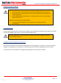
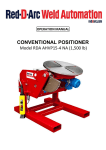
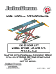
USER MANUAL CONVENTIONAL ROTATORS Model RDA CR125 CE/NA 125T Conventional Welding Rotators Conventional Rotators Model RDA-CR125-UL Table of Contents 1.0 Preface ........................................................................................................................................................ 4 1.1 Using This Manual ................................................................................................................................... 4 1.2 Safety Notices ......................................................................................................................................... 5 1.3 Disclaimer................................................................................................................................................ 5 2.0 Introduction ................................................................................................................................................ 6 2.1 Purpose and Function of Welding Rotators ............................................................................................ 6 2.2 Nomenclature Used in this Manual ........................................................................................................ 6 3.0 Safety .......................................................................................................................................................... 7 3.1 Introduction ............................................................................................................................................ 7 3.2 Safety Rules ............................................................................................................................................. 7 3.3 Users ....................................................................................................................................................... 7 3.4 Workspace .............................................................................................................................................. 8 3.5 Emergency Stops ..................................................................................................................................... 8 3.6 Non Compliant Operation ....................................................................................................................... 9 3.7 Warning Signs ......................................................................................................................................... 9 3.8 Emission and Environmental Information .............................................................................................. 9 4.0 Operating Instructions .............................................................................................................................. 10 4.1 Machine Details .................................................................................................................................... 10 4.2 Control Panel......................................................................................................................................... 10 4.3 Pendant ................................................................................................................................................. 11 4.4.1 Set UP ................................................................................................................................................. 12 4.4.2 Adjusting the Wheel Brackets ............................................................................................................ 13 4.4.3 Included Angle ................................................................................................................................... 13 4.5.1 Switching On ...................................................................................................................................... 14 4.5.2 Operating the Rotators ...................................................................................................................... 15 4.5.3 Welding .............................................................................................................................................. 15 4.5.4 Stopping the Rotators ........................................................................................................................ 15 4.6 Common Mistakes When Using Conventional Rotators ...................................................................... 16 4.7 Breakdowns........................................................................................................................................... 18 4.8 Cleaning................................................................................................................................................. 18 5.0 Maintenance and Servicing ....................................................................................................................... 19 5.1 General .................................................................................................................................................. 19 5.2 Installation ............................................................................................................................................ 19 5.3 First Time Run in ................................................................................................................................... 19 5.4 Storage .................................................................................................................................................. 20 Red D Arc Welderentals Version v1.0 667 South Service Rd., Grimsby, ON L3M 4G1 Phone: 905.643.4910 Efax: 905.963.7810 Website: reddarc.com Page - 2 - Conventional Rotators Model RDA-CR125-UL 5.5 Repair and Maintenance ....................................................................................................................... 20 5.6 Repairs and Replacement Parts ............................................................................................................ 21 6.0 Replacement Parts .................................................................................................................................... 21 6.1 MECHANICAL PARTS LIST ...................................................................................................................... 21 6.2 ELECTRICAL PARTS LIST ......................................................................................................................... 22 Appendix A – Overview Drawings and Specification ...................................................................................... 23 Appendix B – Wiring Diagram ......................................................................................................................... 25 Appendix C – Inverter Parameter Settings ..................................................................................................... 26 Appendix D – Gearbox Maintenance .............................................................................................................. 27 Appendix E – UL Listing Information ............................................................................................................... 28 Table of Illustrations ....................................................................................................................................... 30 Red D Arc Welderentals Version v1.0 667 South Service Rd., Grimsby, ON L3M 4G1 Phone: 905.643.4910 Efax: 905.963.7810 Website: reddarc.com Page - 3 - Conventional Rotators Model RDA-CR125-UL 1.0 PREFACE This user’s manual describes the everyday use and maintenance of our Conventional Rotator sets. Any actions that are required to be carried out by the manufacturer have not been included in this manual. This manual is part of the machine. Please keep this manual safe. Information in this manual could be useful at a later time or when a repair or maintenance is carried out. We suggest that a copy of the manual is made and kept with the machine; the original should be kept in a safe place. If necessary, replacement copies can be supplied. If the machine is sold at a later date then the manual should be also supplied with it to the new user. 1.1 USING THIS MANUAL The instruction in this manual are arranged for various personnel at the end users factory. The definitions in this manual, for these users are as follows; User : The collective term for anyone working at or on the rotators Operator: This is the person that operates or drives the machinery on a daily basis. Read Chapters: 2 Introduction, 3 Safety and 4 Operation. Service Engineer Personnel trained and experienced in maintenance and repair of mechanical or electrical elements of machine systems. Read Chapters: ALL CHAPTERS Safety Officer The person responsible for site safety procedures at the location where the rotators are installed. Where no Safety Officer is designated, then this will be the employer. Read Chapters : 2 Introduction, 3 Safety and 4 Operation In this manual the word “vessel” is used to mean any component or device that is handled on the rotators. All the pictures and diagrams used in this manual are purely for illustrative purposes only, to help explain instructions in the text. The actual equipment supplied may deviate slightly from those illustrated. Red D Arc Welderentals Version v1.0 667 South Service Rd., Grimsby, ON L3M 4G1 Phone: 905.643.4910 Efax: 905.963.7810 Website: reddarc.com Page - 4 - Conventional Rotators Model RDA-CR125-UL 1.2 SAFETY NOTICES The following Safety notices in this document are organized as follows: Safety notice I Description Disregarding the safety regulations and guidelines can be life-threatening. Danger! ! Disregarding the safety regulations and guidelines can result in severe injury or heavy damage to the rotators and/or vessel. Warning! $ Disregarding the safety regulations and guidelines can result in injury or damage to the rotators and/or vessel. Caution! Important information used to prevent errors. Information: 1.3 DISCLAIMER We reserve the right to change the content of this manual without prior notice. The information contained herein is believed to be accurate as of the date of publication, however, Key Plant Automation Ltd, makes no warranty, expressed or implied, with regards to the products or the documentation contained within this document. Key Plant Automation Ltd., shall not be liable in the event if incidental or consequential damages in connection with or arising from the furnishing, performance or use of these products. The software names, hardware names and trademarks used in this document are registered by the respective companies. Red D Arc Welderentals Version v1.0 667 South Service Rd., Grimsby, ON L3M 4G1 Phone: 905.643.4910 Efax: 905.963.7810 Website: reddarc.com Page - 5 - Conventional Rotators Model RDA-CR125-UL 2.0 INTRODUCTION 2.1 PURPOSE AND FUNCTION OF WELDING ROTATORS The Conventional Rotator is designed to aid the welding of cylindrical vessels. By using independent drive and idler units, vessels of varying lengths can be placed on the rotators supported on the rotator wheels. The wheels can be adjusted on the base frame to accommodate different vessel diameters. 2.2 NOMENCLATURE USED IN THIS MANUAL Below are listed explanations of commonly used phrases used in this manual. Drive Unit Rotator Section with Powered Wheels Idler Unit Rotator Section with Free Wheeling Wheels. Rotator Set A set consists of 1 drive unit and 1 or more idler units Baseframe The frame the drive or idler wheels are mounted on. These are pre-drilled so that the wheel brackets can be positioned for different vessel diameters. Wheel Bracket The bracket which houses the rotator wheels. This is bolted down to the baseframe. Panel Electrical control box mounted on the Drive Unit Pendant Operators hand control Pendant Red D Arc Welderentals Version v1.0 667 South Service Rd., Grimsby, ON L3M 4G1 Phone: 905.643.4910 Efax: 905.963.7810 Website: reddarc.com Page - 6 - Conventional Rotators Model RDA-CR125-UL 3.0 SAFETY 3.1 INTRODUCTION These welding rotators have been designed and manufactured in such a way that they can be used and maintained safely. This relies on following the instructions as detailed in this manual, therefore it is necessary for anyone working with or on this machine to have read this manual. 3.2 SAFETY RULES Ensure that children or animals do not have access to the machinery at any time Any safety items fitted, must not be bypassed, or removed. If they have to be removed then the equipment must be put out of operation, until a repair is completed. Always keep the workplace clean and free from obstacles. Make sure that the work area is well lit. Ensure that the machine is regularly maintained to ensure that it remains safe. 3.3 USERS OPERATORS The rotators may only be operated by adults, who have read and understood this manual, in particular the sections on Safety and Operating Instructions. Specialised training is not necessary, but experience in working with this kind of equipment is required. The tasks of the operator will include; Moving the wheel brackets on the baseframe to accommodate different vessel diameters. Loading vessels onto the rotators Operating the machine Daily Maintenance Checks Watching the rotators and vessel while it is turning. Keeping the rotators clean. SERVICE ENGINEERS Service Engineers must be aware of the extra risks when working on the machine. As well as the above knowledge for operators, the service engineer must also; Have received the required training/education or knowledge as necessary for the local regulations regarding service engineers. Must have experience in maintaining and servicing machinery. Have access to correct tools required to service/repair the machinery. Red D Arc Welderentals Version v1.0 667 South Service Rd., Grimsby, ON L3M 4G1 Phone: 905.643.4910 Efax: 905.963.7810 Website: reddarc.com Page - 7 - Conventional Rotators Model RDA-CR125-UL 3.4 WORKSPACE ! By this we mean a clear space around the drive and idler units of around 1500mm. From within the workspace all operations and servicing can be carried out. Ensure that any protrusions on the vessel cannot cause any injury or damage. 3.5 EMERGENCY STOPS I It is vitally important for the safety of the operators and any other personnel in the area of the rotators, that the operator fully understands the location and how to use the emergency stop buttons on the machines. It is also recommended that other personnel that work in the vicinity of the rotators are also aware of the positions of emergency stop buttons, so they can stop the equipment if the operator requires assistance or is trapped by the machines Firstly all new operators should be made aware of these emergency stop procedures. There are two emergency stop buttons fitted to the rotators, one is located on the panel mounted on the drive unit, the second is mounted on the pendant. Pressing either of these two buttons will immediately bring the rotators to a stop, and all controls will be locked. In case of personal injury, help can be given immediately, also if there is other urgent action required this can be carried out immediately. After the hazard has been resolved and after checking the machine can be safely operated again, the emergency stop button needs to be released by twisting it in the direction of the arrows printed on it. Once this is done the reset button on the panel needs to be pressed and will illuminate. Once the light comes on, the rotators will not restart again, until a direction button is pressed. Normal operation will now continue. Note either emergency stop button can be used to stop the machine but operation can only restart again once the reset button is pressed. I We recommend New operators are allowed to practise with the emergency stop switches The Emergency Stop is tested at the start of every shift NEVER DISCONNECT OR BYPASS THE EMERGENCY STOP BUTTONS Red D Arc Welderentals Version v1.0 667 South Service Rd., Grimsby, ON L3M 4G1 Phone: 905.643.4910 Efax: 905.963.7810 Website: reddarc.com Page - 8 - Conventional Rotators Model RDA-CR125-UL 3.6 NON COMPLIANT OPERATION ! These welding rotators are not suitable for the following types of operations. Any Vessel which is heavier than the maximum weight limit for the rotators Any Vessel that is larger/smaller than the maximum/minimum diameter that can be supported. (If the rotators have polyurethane or rubber tyres) Do not use on preheated vessels above 70C. In addition the following is also prohibited; The mounting of additional controls which are not approved by the manufacturer. Operating the rotators when they are incorrectly aligned (see section on setting up the machines) 3.7 WARNING SIGNS On the machines there will be various warning signs. These should be checked to ensure that they remain visible and readable at all times. If necessary order replacements. ! Warning symbols are on the machine for a reason. Check them regularly to ensure they are always affective. 3.8 EMISSION AND ENVIRONMENTAL INFORMATION The rotators themselves do not contain substances that are dangerous to humans. There are no specific dangers in the operation, maintenance or dismantling of this machinery regarding the environment. In the event of a fire standard fire extinguishing equipment may be used as suitable. Red D Arc Welderentals Version v1.0 667 South Service Rd., Grimsby, ON L3M 4G1 Phone: 905.643.4910 Efax: 905.963.7810 Website: reddarc.com Page - 9 - Conventional Rotators Model RDA-CR125-UL 4.0 OPERATING INSTRUCTIONS Before operating the rotators please ensure that you have read Chapter 2 – “Safety”. This chapter of the manual is meant for the operators, though all people concerned with the machines should read it. 4.1 MACHINE DETAILS The rotator set will usually consist of one drive unit and 1, 2 or 3 idler units. The idler unit basically consists of a base frame with two wheel brackets bolted onto the top of it. There are holes drilled through the top of the baseframe so that the wheel brackets can be positioned at different distances apart, to suit the vessel diameter. The drive unit again has two wheel brackets and similar to the idler unit these can be positioned to suit the vessel diameter. Either one or more usually both wheel brackets will be motorised (depending on the model). The wheel is turned by and electric motor through a reduction gearbox. The motor is connected back to the panel on the drive unit. Inside the control panel is an inverter which controls the motors. There is also a hand pendant on a flexible cable connected to the panel. 4.2 CONTROL PANEL 1 2 3 The control panel on the drive unit has the following; 1. Power On Light – Illuminates when the power is connected. 2. Reset Button – for resetting the machine after an emergency stop has occurred. The button will be illuminated to show the rotator needs to be reset. 3. Emergency Stop Button 4. Panel door opening key 5. Door electrical isolator, must be turned off before panel door can open. 4 5 Figure 1 Main Panel Red D Arc Welderentals Version v1.0 667 South Service Rd., Grimsby, ON L3M 4G1 Phone: 905.643.4910 Efax: 905.963.7810 Website: reddarc.com Page - 10 - Conventional Rotators Model RDA-CR125-UL 4.3 PENDANT The hand pendant has the following controls Rotation direction push buttons, forward reverse and stop. Note as soon as one of the direction buttons (Forward or Reverse) are pressed then the rotators will begin to turn the vessel. Speed Control Potentiometer. Turning the knob clockwise increases the rotator speed, and conversely rotating anti-clockwise decreases the speed. Emergency Stop Button, this is located under the guard at the end of the pendant. Figure 2 Hand Control Pendant Red D Arc Welderentals Version v1.0 667 South Service Rd., Grimsby, ON L3M 4G1 Phone: 905.643.4910 Efax: 905.963.7810 Website: reddarc.com Page - 11 - Conventional Rotators Model RDA-CR125-UL We recommend that the operator always presses stop, before changing the rotation direction. 4.4.1 SET UP After delivery and setting into place these rotators will be ready for use. Firstly choose a place for the rotators to be located. This should have suitable access to the machines. Also enough space around the machines including vessel when loaded. It should also be positioned in such a way as to allow easy unhindered load and unloading of vessels onto the rotators by either overhead crane or other lifting devices. ! Always ensure that there is sufficient space around the machine. See section 3.4 of this manual. When moving the rotators, the correct lifting equipment must be used. Either correctly rated overhead cranes or forklift trucks can be used. ! Forklift Truck: When lifting the rotators using a forklift truck, use the slots in the long side of the frames for the forks. Take notice of the positions of the wheel brackets on the frames in case they cause an imbalance when lifting the frame. Ensure that they are both at an equal distance from the centreline of the frame, and that they are properly bolted to the frame and will not move during lifting. Lifting by crane: The rotators can be lifted by using the lifting points on the rotator wheel brackets. One lifting point on each side of the wheel bracket should be used, (4 lifting points in all). It is desirable that the angle between the chain and the lifting points on the rotators makes a 60 angle (see figure 3). Figure 3 Lifting Chain Angles The rotators should be placed on a smooth, level, hard floor that is capable of taking the weight of the rotator and vessel, over the contact area of the rotator with the floor. The distances between the baseframes should be such as to match the vessels dimensions. Ideally if the vessel is perfectly symmetrical and 1 drive with 1 idler are being used. The drive and idler should be one third of the way along the vessel length to ensure that equal load is put onto each section. If more weight is at one end of the vessel, then drive or idler section should be moved closer to this end to again balance the loading on each section. Red D Arc Welderentals Version v1.0 667 South Service Rd., Grimsby, ON L3M 4G1 Phone: 905.643.4910 Efax: 905.963.7810 Website: reddarc.com Page - 12 - Conventional Rotators Model RDA-CR125-UL $ It is important to balance the loading equally between the drive and idler section(s). Failure to do so may result in overloading one of the sections which will cause problems when trying to rotate the vessel (wheels slipping). It can also result in backdriving where the vessel can continue to rotate after stopping the rotators. If observed this must be rectified by correctly positioning the drive and idler section, failure to do so will cause damage to the equipment. ! WARNING! As soon as one of the direction buttons (Forward or Reverse) is pressed then the rotators will begin to turn the vessel. 4.4.2 ADJUSTING THE WHEEL BRACKETS The operator will need to adjust the positions of the two wheel brackets on the baseframe, so that vessels of different diameters can be loaded. To do this, the operator needs to; 1. 2. 3. 4. Unbolt the wheel bracket from the baseframe. Use a crane to lift the wheel bracket using the lifting points. Move the bracket to the required position for the diameter of the vessel. Bolt the wheel brackets back onto the baseframe using all the bolts, and tighten. We recommend that the wheel brackets are always adjusted so that the axis of rotation of the vessel, is on the centre line of the drive and idler frames of the set of rotators. See section 4.6 for details of the distances between the two wheel brackets 4.4.3 INCLUDED ANGLE The distance between the wheel brackets on both the drive and idler sections will depend on the diameter of the vessel. The included angle must be between 50 and 80, but we recommend setting the rotators up always as close to 60 as possible. The included angle is the angle between two lines from the centre of the rotation axis of the vessel to the centre of each wheel on the drive or idler section. It is of importance, as the angle increases so does the resulting load on each wheel, and consequently the load on the bearings. Also by increasing the angle more torque, and therefore more power, is required to rotate the vessel. Red D Arc Welderentals Version v1.0 667 South Service Rd., Grimsby, ON L3M 4G1 Phone: 905.643.4910 Efax: 905.963.7810 Website: reddarc.com Page - 13 - Conventional Rotators Model RDA-CR125-UL Figure 4 Diagram Showing Included Angle You can quickly calculate the distance that the wheel brackets need to be apart in order to achieve a 60 included angle. It is; 4.5.1 SWITCHING ON Before switching on the rotators, check the following; Are the wheel brackets correctly bolted down on the baseframe. Visually inspect the wheels, motors, gearboxes, pendant, panel and cables for any signs of damage. Are the wheels correctly positioned under the vessel? Are there any obstructions to prevent rotation of the vessel (if one is loaded)? ! WARNING! Do not operate the rotators if there are signs of damage, always have a service engineer to check these over and make repairs if necessary. Once the operator is satisfied that the rotators are in good order, plug in the mains lead to the power supply. ! ! WARNING! Check that the mains power supply matches the electrical voltage shown on the panel. WARNING! Ensure that the mains and pendant cables, do not cross lanes where forklift trucks or other vehicles can run over them, and they do not create a tripping hazard. Switch on the mains power, and the Power On lamp on the control panel should illuminate. Red D Arc Welderentals Version v1.0 667 South Service Rd., Grimsby, ON L3M 4G1 Phone: 905.643.4910 Efax: 905.963.7810 Website: reddarc.com Page - 14 - Conventional Rotators Model RDA-CR125-UL Check that the emergency stop buttons are not pressed in, and then press the reset button. The machine is now ready to operate. 4.5.2 OPERATING THE ROTATORS Once the operator is happy the rotators are correctly aligned and the wheel brackets are in the correct position, they may then load the vessel on the rotators. This must be done steadily, so as not to shock load the rotators. If the rotators are shock loaded then this will cause damage to the drive chain. Ensure that no protuberances on the vessel can strike objects around the rotators, or the floor during rotation. The operator should then set the speed potentiometer knob (see figure 2) to the desired speed. Then press the desired travel direction (GREEN or YELLOW button) the rotators will then start to turn the vessel. 4.5.3 WELDING It is important that the user is aware of the earthing requirements of their welding procedure, and that this is correctly connected to the vessel before welding. Standard rotators are not designed to earth the vessel during welding. ! WARNING! When welding, the vessel MUST be earthed independently of the rotators. Earthing through the rotator will cause serious damage to the rotator sets. The only exception to this would be, for special steel wheel rotators which have been fitted with an earthing point. In which case it is essential that the earth cable is connected properly at this earthing point, before welding. It is good practise to keep the rotators clean. Any arc sparks, flux or slag that falls onto the rotators should be removed as soon as is possible. 4.5.4 STOPPING THE ROTATORS To stop the rotators, press the RED stop button on the hand pendant. This will stop rotation. Rotation will start again when a direction button is pressed. If necessary the rotators can be stopped using the Emergency Stop Button on either the panel or hand pendant. This should only be used in an emergency. Red D Arc Welderentals Version v1.0 667 South Service Rd., Grimsby, ON L3M 4G1 Phone: 905.643.4910 Efax: 905.963.7810 Website: reddarc.com Page - 15 - Conventional Rotators Model RDA-CR125-UL 4.6 COMMON MISTAKES WHEN USING CONVENTIONAL ROTATORS 1. Placing multiple drives under one vessel. This is only possible if special Master and Slave synchronised control panels have been supplied with the rotators. In which case the master panel controls the slave drive. 2. Parts of the vessel come into contact with the rotators, floor or objects in the vicinity during rotation. This can cause damage to the rotators and cause the wheels to slip or overload the units. 3. No proper earthing during welding. This can cause the electrics on the rotators to short out. 4. Emergency Stop button is depressed. If a switch is pressed in, the operator must find out who pressed it in and for what reason, before restarting the machine. There may be a hazard that someone else has seen and stopped the machine for. 5. The distance between the wheel brackets is too large, thus causing more load to be put through each wheel. This in turn can cause the rotators to be overloaded. Figure 5 Wheel Brackets Too Far Apart 6. Wheel brackets are too close together. I This is a very unsafe position. During rotation the vessel could now roll off the rotators causing very serious injury to anyone in the vicinity of the rotators. It can also happen if there is an out of balance load i.e. the centre of gravity of the vessel is offset from the axis of rotation. The rotators should never be operated at an included angle of less than 46. Figure 6 Wheel Brackets Too Close Together Red D Arc Welderentals Version v1.0 667 South Service Rd., Grimsby, ON L3M 4G1 Phone: 905.643.4910 Efax: 905.963.7810 Website: reddarc.com Page - 16 - Conventional Rotators Model RDA-CR125-UL 7. If the drive and idler units are not aligned parallel to each other then the vessel can creep lengthways and even fall off the rotators. This can also cause wear and damage to the wheels of the rotator. See Figure 7 below for correct alignment details. Figure 7 Diagram Showing Correct Alignment Procedure Between Drive and Idler Sections Red D Arc Welderentals Version v1.0 667 South Service Rd., Grimsby, ON L3M 4G1 Phone: 905.643.4910 Efax: 905.963.7810 Website: reddarc.com Page - 17 - Conventional Rotators Model RDA-CR125-UL 4.7 BREAKDOWNS If the rotators stop working, then the equipment must only be repaired by qualified service personnel. If there are repeat faults, then this could indicate a problem with the machines. Inform the person on site that is responsible for service and maintenance. 4.8 CLEANING These rotators require no special cleaning instructions. The rotators should not create any pollution to the environment around them during normal operation, although, the welding process being carried out on them may pollute the rotators. ! It is good practise to keep the rotators clean. Any arc sparks, flux or slag that falls onto the rotators should be removed as soon as is possible. WARNING! Rotators must be electrically isolated before cleaning. Any electrical components must not come in contact with water or other cleaning fluids. Red D Arc Welderentals Version v1.0 667 South Service Rd., Grimsby, ON L3M 4G1 Phone: 905.643.4910 Efax: 905.963.7810 Website: reddarc.com Page - 18 - Conventional Rotators Model RDA-CR125-UL 5.0 MAINTENANCE AND SERVICING This chapter should be read by all service engineers that will be working on these rotators. 5.1 GENERAL ! ! WARNING! During all maintenance or repair procedures, the rotators must be electrically isolated. Do this by switching off the main electrical supply and unplugging the mains cable. WARNING! After disconnecting the power there may be some residual charge in some components in the panel. Wait a few minutes after disconnecting the mains power before commencing work on any electrical elements of the machine. 5.2 INSTALLATION Before first use, or after maintenance or repair work, or after a period of the rotators being in storage, they will need to go through this installation procedure. Before the rotators were despatched from the factory, they will have been fully tested on correct functioning and therefore they can be directly put into operation without the need for any further test time. We would though recommend that the operations of all controls are tested before the equipment is put into the production process. Before starting up, check the following; All moving parts can freely move (wheels) Check oil level in the gearbox (see appendix D for Lubrication of the gearboxes) Check the integrity of all cables, mains and hand control pendant, make sure there are no cuts etc. Check the hand pendant controls all operate correctly. Check the Emergency Stop on the Pendant works, and locks all other controls so the machine cannot restart then reset on the panel. Check the Emergency Stop on the Panel works, and locks all other controls so the machine cannot restart then reset on the panel. Check the steel framework to ensure it is straight and free from damage. 5.3 FIRST TIME RUN IN In order for the worm gearbox to reach its optimal efficiency, when first installed the rotators should be run in both directions for the following periods of time. At least 8 hours running with no load on the rotators 10 hours running with one third loading. 15 hours running with two third loading. After running in for the above the rotators can be run with full loading. The Gearbox oil should be flushed out and changed after the first 100 hours of operation. After this period follow the lubrication guide in Appendix D. Red D Arc Welderentals Version v1.0 667 South Service Rd., Grimsby, ON L3M 4G1 Phone: 905.643.4910 Efax: 905.963.7810 Website: reddarc.com Page - 19 - Conventional Rotators Model RDA-CR125-UL 5.4 STORAGE There are no specific requirements for storage other than they are stored in a cool dry place. After a long period of storage the machines will need to be checked over thoroughly before being put into use again. ! $ WARNING! After storing or transporting the rotators in a cold climate and moving them into a warm location, there may be a build up of condensation within the machine and electrical controls. To prevent damage, allow the machine to adjust to the new environment temperature. Do not store these rotators outside unprotected. The rotators should be sheeted, and bare metal areas, bearings, gears and shafts suitably greased to prevent corrosion. 5.5 REPAIR AND MAINTENANCE These rotators are designed and constructed to the highest standards, using high quality components. As such this equipment should expect to have many years of operational life with only a minimal amount of regular maintenance. To continue the longevity of the equipment, all efforts should be made to keep the rotators clean and free from dirt or waste from the welding process. In addition the gearbox oil levels should be checked regularly and kept at the correct levels, see Appendix D, for more information on gearbox maintenance. At least one per year the whole installation should be inspected with particular attention paid to the following; Poor electrical contacts Switches and controls Loose mechanical parts, ensure all fixings are correctly tightened Condition of tyres on wheels (if fitted) Condition of solid steel wheels (if fitted) Check wheels rotate truly (i.e. no eccentric rotation around the axles). Metal corrosion Fame damage Check for signs of damage to the wheel bearings. Follow maintenance procedure for the gearboxes in Appendix D Check all cables for damage (mains, pendant and also any visible cable running from the panel to the motors). Check the emergency stops and also the correct functioning of the panel door isolator. Remove guards and check the condition of the spur gear and pinion on the drive wheels. If there is any excessive damage then the parts should be removed and replaced with new. Red D Arc Welderentals Version v1.0 667 South Service Rd., Grimsby, ON L3M 4G1 Phone: 905.643.4910 Efax: 905.963.7810 Website: reddarc.com Page - 20 - Conventional Rotators Model RDA-CR125-UL 5.6 REPAIRS AND REPLACEMENT PARTS During the warranty period repairs must only be carried out under the direction of the manufacturers. Any unauthorised repairs may damage the machine and invalidate the warranty. It is advised that the manufacturer should be contacted for the supply of all replacement parts; this will ensure that the correct part or suitable alternative parts are supplied and used on the equipment. 6.0 REPLACEMENT PARTS ! WARNING! Not following the recommendations for replacement parts in section 5.5 can have consequences for the safety of the equipment. The manufacturers cannot be held liable for any subsequent problems after fitting none recommended parts. 6.1 MECHANICAL PARTS LIST Part Number Drive Section KPCR125D001 KPCR125D002 KPCR125D010 KPCR125D003 KPCR125D035 KPCR125D016 KPCR125D017 KPCR125D004 KPCR125D018 KPCR125D030 KPCR125D005 KPCR125D032 KPCR125D033 KPCR125D006 Idler Section KPCR125I007 KPCR125I008 KPCR125I011 KPCR125I035 KPCR125I012 KPCR125I030 KPCR125I009 Description Quantity Base Frame Wheel Bracket Wheel Wheel Keeplate Duthane Tyre Spur Gear Pinion Pinion Keep Plate Drive Shaft Wheel Shaft Bearing Wheel Shaft Bearing Keeplate Reduction Gearbox 3.0kW AC Motor with Force Vent Fan Set of Wheel Bracket Guards 1 2 2 4 8 2 2 2 2 4 4 2 2 2 Idler Base Frame Idler Wheel Bracket Idler Wheel Duthane Tyres Idler Shaft Wheel Shaft Bearing Wheel Shaft Bearing Keeplate 1 2 2 8 2 4 4 Red D Arc Welderentals Version v1.0 667 South Service Rd., Grimsby, ON L3M 4G1 Phone: 905.643.4910 Efax: 905.963.7810 Website: reddarc.com Page - 21 - Conventional Rotators Model RDA-CR125-UL 6.2 ELECTRICAL PARTS LIST 1 2 34 5 6 8 7 14 15 16 9 17 18 19 11 12 10 13 10 20 Figure 10 Panel Inside Photo No. 1 2 3 4 5 6 7 8 9 10 11 12 13 14 15 16 17 18 19 20 Not Shown Part Number KPCR125201UL KPCR125202UL KPCR125204UL KPCR125205UL KPCR125203UL KPCR125203UL KPCR125206UL KPCR125207UL KPCR125208UL KPCR125209UL KPCR125210UL KPCR125211UL KPCR125220UL KPCR125212UL KPCR125213UL KPCR125214UL KPCR125215UL KPCR125216UL KPCR125217UL KPCR125218UL KPCR125219UL Figure 9 Panel Door Figure 8 Hand Pendant Description 24V Transformer 63VA Contactor 11 kW, 25A 2 Pole Circuit Breaker 0.5A 1 Pole Circuit Breaker 3A 3 Phase Fuse Holder and Fuses 1A 3 Phase Fuse Holder and Fuses 20A 7.5 kW 3 Phase Inverter Drive Motor Circuit Breaker With Aux Block (Drive Motor) Motor Circuit Breaker (Force Vent Fan Motor) Fused Door Isolator inc 3 Fuses 25A Standard Terminals (Grey) Earth Terminals (Green/Yellow) 10-Way Earthing Bar White Power On Lamp Emergency Stop Reset Blue LED Push Button Panel Emergency Stop Button 4 Button Pendant Body plus Emergency Stop Button Guard Pendant Pushbutton (Green, Red, Yellow) Speed Potentiometer Pendent Emergency Stop Button Pendant Cable Quantity 1 1 1 1 1 1 1 2 2 1 21 5 1 1 1 1 1 3 1 1 8m Red D Arc Welderentals Version v1.0 667 South Service Rd., Grimsby, ON L3M 4G1 Phone: 905.643.4910 Efax: 905.963.7810 Website: reddarc.com Page - 22 - Conventional Rotators Model RDA-CR125-UL APPENDIX A – OVERVIEW DRAWINGS AND SPECIFICATION Figure 11 Drive Section GA Drawing & Specification Red D Arc Welderentals Version v1.0 667 South Service Rd., Grimsby, ON L3M 4G1 Phone: 905.643.4910 Efax: 905.963.7810 Website: reddarc.com Page - 23 - Conventional Rotators Model RDA-CR125-UL Figure 12 Idler Section GA Drawing & Specification Red D Arc Welderentals Version v1.0 667 South Service Rd., Grimsby, ON L3M 4G1 Phone: 905.643.4910 Efax: 905.963.7810 Website: reddarc.com Page - 24 - Conventional Rotators Model RDA-CR125-UL APPENDIX B – WIRING DIAGRAM Red D Arc Welderentals Version v1.0 667 South Service Rd., Grimsby, ON L3M 4G1 Phone: 905.643.4910 Efax: 905.963.7810 Website: reddarc.com Page - 25 - Conventional Rotators Model RDA-CR125-UL APPENDIX C – INVERTER PARAMETER SETTINGS The following settings have been programmed into the inverter at the factory; Parameter Number 1 2 3 4 5 6 7 Value 2.5 50 2 2 AI.AV 16.5 1500 Parameter Number 8 9 10 11 22 41 Value 400 0.85 L3 1 A FD All other values are as factory set by the inverter manufacturer and need not be altered. Yellow Button on Pendant – Reverse gives clockwise rotation when looking at the drive rotator section with the gearboxes on the side closest you. Therefore Green button is Anti-Clockwise when looking from the same position. Note: Rotation motor overloads are set to 7.0A, and force vent overloads to 0.4A Red D Arc Welderentals Version v1.0 667 South Service Rd., Grimsby, ON L3M 4G1 Phone: 905.643.4910 Efax: 905.963.7810 Website: reddarc.com Page - 26 - Conventional Rotators Model RDA-CR125-UL APPENDIX D – GEARBOX MAINTENANCE INSPECTION AND MAINENANCE To ensure these rotators have a long service life you should regularly check and change the oil in the gearboxes. Also the following maintenance checks should be regularly carried out. 1. Except for the first oil change, the oil in the gearbox should be changed every 2500 hours or 6 months. 2. Check if the seal is leaking or irregular. 3. Check if there are any unusual noises during operation. If yes, the bearing may be broken. 4. Check the breathing hole of gearbox is obstruction free. 5. To aid cooling of the gearbox it is recommended that the external housing is kept clean. 6. Check the bolts, re-tighten any that are loose. LUBRICATION The gearboxes on the rotators were filled with the proper quantity of lubricant before leaving the factory. Please see the following table of recommended oils to use in the gearboxes. Note do not mix oils of different brands. Instead drain the oil from the gearbox before refilling with a different brand. Selection Table of Lubricant Standard load / Input 600 RPM or over 600 RPM Temperature(°C) CPC ISO VG Mobil -30 ~-15 HD 100 VG 100 Mobilgear 627 -15 ~- 3 HD 150 VG 150 Mobilgear 629 -3 ~23 HD 220 VG 220 Mobilgear 630 23 ~40 HD 320 VG 320 Mobilgear 632 40 ~80 HD 460 VG 460 Mobilgear 634 Shell Omala 100 Omala 150 Omala 220 Omala 320 Omala 460 Heavy load / Input 600 RPM or over 600 RPM Temperature(°C) CPC -30 ~-15 HD 150 -15 ~- 3 HD 220 -3 ~23 HD 320 23 ~40 HD 460 40 ~80 HD 680 Shell Omala 150 Omala 220 Omala 320 Omala 460 Omala 680 ISO VG VG 150 VG 220 VG 320 VG 460 VG 680 Mobil Mobilgear 629 Mobilgear 630 Mobilgear 632 Mobilgear 634 Mobilgear 636 1. Before replacing the oil, the inside of the gearbox should be cleaned, and the old oil drained out. 2. During the operation, if the heat is over 80C or any abnormal noise is hears, please shut down and check immediately. Do not start to run again until the problem has been identified and resolved. Red D Arc Welderentals Version v1.0 667 South Service Rd., Grimsby, ON L3M 4G1 Phone: 905.643.4910 Efax: 905.963.7810 Website: reddarc.com Page - 27 - Conventional Rotators Model RDA-CR125-UL APPENDIX E – UL LISTING INFORMATION Red D Arc Welderentals Version v1.0 667 South Service Rd., Grimsby, ON L3M 4G1 Phone: 905.643.4910 Efax: 905.963.7810 Website: reddarc.com Page - 28 - Conventional Rotators Model RDA-CR125-UL Red D Arc Welderentals Version v1.0 667 South Service Rd., Grimsby, ON L3M 4G1 Phone: 905.643.4910 Efax: 905.963.7810 Website: reddarc.com Page - 29 - Conventional Rotators Model RDA-CR125-UL TABLE OF ILLUSTRATIONS Figure 1 Main Panel ........................................................................................................................................ 10 Figure 2 Hand Control Pendant ...................................................................................................................... 11 Figure 3 Lifting Chain Angles ........................................................................................................................... 12 Figure 4 Diagram Showing Included Angle ..................................................................................................... 14 Figure 5 Wheel Brackets Too Far Apart .......................................................................................................... 16 Figure 6 Wheel Brackets Too Close Together ................................................................................................. 16 Figure 7 Diagram Showing Correct Alignment Procedure Between Drive and Idler Sections ...................... 17 Figure 8 Hand Pendant ................................................................................................................................... 22 Figure 9 Panel Door......................................................................................................................................... 22 Figure 10 Panel Inside ..................................................................................................................................... 22 Figure 11 Drive Section GA Drawing & Specification ...................................................................................... 23 Figure 12 Idler Section GA Drawing & Specification ....................................................................................... 24 Red D Arc Welderentals Version v1.0 667 South Service Rd., Grimsby, ON L3M 4G1 Phone: 905.643.4910 Efax: 905.963.7810 Website: reddarc.com Page - 30 - Conventional Rotators Model RDA-CR125-UL INDEX Baseframe....................................................................................... 6 bearing.......................................................................................... 27 Breakdown.................................................................................... 18 oil levels........................................................................................ 20 Operating ..................................................................................... 15 Operating Instructions ................................................................. 10 Operator ......................................................................................... 4 OPERATORS ................................................................................... 7 Overview ...................................................................................... 23 C P CE Certificate of Conformity ......................................................... 28 Cleaning ........................................................................................ 18 Common Mistakes ........................................................................ 16 Contents ......................................................................................... 2 Panel ............................................................................ 6, 10, 19, 22 PARTS LIST Electrical.................................................................................. 22 Mechanical .............................................................................. 21 Pendant ........................................................................ 6, 11, 19, 22 Preface ........................................................................................... 4 B D Disclaimer ....................................................................................... 5 Drawing .................................................................................. 23, 24 Drive Unit........................................................................................ 6 E R Replacement Parts ....................................................................... 21 Replacment Parts ......................................................................... 21 Rotator Set ..................................................................................... 6 Emergency Stops ............................................................................ 8 Emissions ........................................................................................ 9 G gearbox ....................................................................... 10, 19, 20, 27 Gearbox Maintenance .................................................................. 27 I Idler Unit ......................................................................................... 6 Included Angle .............................................................................. 13 Installation .................................................................................... 19 Introduction .................................................................................... 6 Inverter Parameter ....................................................................... 26 S Safety Notices ................................................................................ 5 Safety Officer.................................................................................. 4 Safety Rules .................................................................................... 7 Service Engineer ............................................................................. 4 SERVICE ENGINEERS ...................................................................... 7 Signs ............................................................................................... 9 Specification ........................................................................... 23, 24 starting up .................................................................................... 19 Stopping the Rotators .................................................................. 15 Storage ......................................................................................... 20 Switching On ................................................................................ 14 U M User ............................................................................................ 1, 4 Machine Details ............................................................................ 10 Maintenance....................................................................... 7, 19, 20 Motor Information ....................................................................... 28 W N Nomenculture................................................................................. 6 Welding ........................................................................................ 15 Wheel Bracket .......................................................................... 6, 21 Adjustment ............................................................................. 13 Wiring Diagram ............................................................................ 25 Workspace ..................................................................................... 8 O oil change ..................................................................................... 27 Red D Arc Welderentals Version v1.0 667 South Service Rd., Grimsby, ON L3M 4G1 Phone: 905.643.4910 Efax: 905.963.7810 Website: reddarc.com Page - 31 -