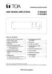
1
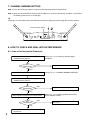
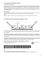
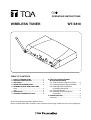
OPERATING INSTRUCTIONS
WIRELESS TUNER
WT-5810
TABLE OF CONTENTS
1.
2.
3.
4.
5.
SAFETY PRECAUTIONS ........................... 2
GENERAL DESCRIPTION ......................... 3
FEATURES ................................................. 3
HANDLING PRECAUTIONS ...................... 3
NOMENCLATURE AND FUNCTIONS
Front ............................................................ 4
Rear ............................................................. 4
6. OPERATION ............................................... 5
7. CHANNEL NUMBER SETTING ................. 6
8. HOW TO CHECK AND DEAL
WITH INTERFERENCE
8.1. Order of Actions (Action Flowchart) ..... 6
8.2. Checking Ambient Signal Condition ..... 7
8.3. Reducing Radio Interference
by the Squelch Control ......................... 7
8.4. Channel Detection ................................ 8
8.5. Rewriting the Inner Emphasis
Circuit Data ........................................... 8
9. SPECIFICATIONS ...................................... 8
Accessory .................................................... 8
Thank you for purchasing TOA's Wireless Tuner.
Please carefully follow the instructions in this manual to ensure long, trouble-free use of your equipment.
1. SAFETY PRECAUTIONS
• Be sure to read the instructions in this section carefully before use.
• Make sure to observe the instructions in this manual as the conventions of safety symbols and messages
regarded as very important precautions are included.
• We also recommend you keep this instruction manual handy for future reference.
Safety Symbol and Message Conventions
Safety symbols and messages described below are used in this manual to prevent bodily injury and property
damage which could result from mishandling. Before operating your product, read this manual first and
understand the safety symbols and messages so you are thoroughly aware of the potential safety hazards.
WARNING
Indicates a potentially hazardous situation which, if mishandled, could
result in death or serious personal injury.
When Installing the Unit
• Do not expose the unit to rain or an environment where it may be splashed by water or other liquids, as
doing so may result in fire or electric shock.
• Use the unit only with the voltage specified on the unit. Using a voltage higher than that which is specified
may result in fire or electric shock.
• Do not cut, kink, otherwise damage nor modify the power supply cord. In addition, avoid using the power
cord in close proximity to heaters, and never place heavy objects -- including the unit itself -- on the power
cord, as doing so may result in fire or electric shock.
• Avoid installing or mounting the unit in unstable locations, such as on a rickety table or a slanted surface.
Doing so may result in the unit falling down and causing personal injury and/or property damage.
• To prevent lightning strikes, install the unit at least five meters away from a lightning rod, and yet within the
protective range (angle of 45°) of the lightning conductor. Lightning strikes may cause a fire, electric shock
or personal injury.
• Since the unit is designed for in-door use, do not install it outdoors. If installed outdoors, the aging of parts
causes the unit to fall off, resulting in personal injury. Also, when it gets wet with rain, there is a danger of
electric shock.
When the Unit is in Use
• Should the following irregularity be found during use, immediately switch off the power, disconnect the power
supply plug from the AC outlet and contact your nearest TOA dealer. Make no further attempt to operate the
unit in this condition as this may cause fire or electric shock.
· If you detect smoke or a strange smell coming from the unit.
· If water or any metallic object gets into the unit
· If the unit falls, or the unit case breaks
· If the power supply cord is damaged (exposure of the core, disconnection, etc.)
· If it is malfunctioning (no tone sounds.)
• Do not place cups, bowls, or other containers of liquid or metallic objects on top of the unit. If they
accidentally spill into the unit, this may cause a fire or electric shock.
• Do not touch the unit's antennas during thunder and lightning, as this may result in electric shock.
CAUTION
Indicates a potentially hazardous situation which, if mishandled, could
result in moderate or minor personal injury, and/or property damage.
When Installing the Unit
• Never plug in nor remove the power supply plug with wet hands, as doing so may cause electric shock.
• When unplugging the power supply cord, be sure to grasp the power supply plug; never pull on the cord
itself. Operating the unit with a damaged power supply cord may cause a fire or electric shock.
• When moving the unit, be sure to remove its power supply cord from the wall outlet. Moving the unit with the
power cord connected to the outlet may cause damage to the power cord, resulting in fire or electric shock.
When removing the power cord, be sure to hold its plug to pull.
2
• The socket outlet shall be installed near the equipment and shall be easily accessible.
• Avoid installing the unit in humid or dusty locations, in locations exposed to the direct sunlight, near the
heaters, or in locations generating sooty smoke or steam as doing otherwise may result in fire or electric
shock.
When the Unit is in Use
• Do not place heavy objects on the unit as this may cause it to fall or break which may result in personal
injury and/or property damage. In addition, the object itself may fall off and cause injury and/or damage.
• Make sure that the volume control is set to minimum position before power is switched on. Loud noise
produced at high volume when power is switched on can impair hearing.
• Never open the unit case as there are high temperature parts inside the unit, which may cause a burn if
touched. Refer all servicing to your nearest TOA dealer.
• Use the dedicated AC-DC adapter for the unit. Note that the use of other adapter may cause a fire.
• If dust accumulates on the power supply plug or in the wall AC outlet, a fire may result. Clean it periodically.
In addition, insert the plug in the wall outlet securely.
• Switch off the power, and unplug the power supply plug from the AC outlet for safety purposes when
cleaning or leaving the unit unused for 10 days or more. A fire or electric shock may result.
2. GENERAL DESCRIPTION
The WT-5810 Wireless Tuner is designed for use on the UHF band, and suitable for vocal or speech
reinforcement applications. It features a compander circuit which minimizes the influence of ambient noise.
3. FEATURES
• 16 different operating frequencies ranging from 692 to 865 MHz.
• An optimized PLL-synthesizer minimizes the oscillation frequency drift resulting from the ambient
temperature change.
• Compact size and high reliability
4. HANDLING PRECAUTIONS
• When installing, keep the unit as far away as possible from fluorescent lamps, digital equipment, personal
computers, and other equipment that generate high frequency noise.
• When cleaning the case, use a dry cloth. Never use benzine, thinner or other volatile liquids.
• When using two or more wireless microphones, keep them at least 50 cm away from each other to avoid
malfunctions or noise.
• Keep the wireless microphone at least 3 m away from the receiving antenna. Using the microphone in close
proximity to the antenna could result in malfunctions or noise.
3
5. NOMENCLATURE AND FUNCTIONS
[Front]
2
3 4 5 6 7
8
1. Power switch
Press this switch to turn the power on, and press it
again to turn off the power.
9
10
1
2
6. Squelch control
Adjusts the squelch level
7. RF check button
Switches off the squelch for monitoring the
receiving frequency.
2. Rod antennas
Raise both antennas at 45° outwards from a
vertical line.
When carrying the unit, be sure to fold down both
antennas to prevent them from break.
8. Channel number display
Indicates the current channel number in normal
state.
In setting mode, the indicated channel number
flashes until registered.
3. Reception lamps
Either lamp of A (left) or B (right) lights yellow
when the tuner receives a radio signal.
9. Channel setting keys (SET and NEXT keys)
Used to select the receiving channel (frequency).
(The tuner frequency must be identical to that of
the microphone.)
4. Battery alarm lamp
Lights when the battery voltage in the
corresponding wireless microphone becomes low.
5. AF peak lamp
Lights red when the tuner output level reaches the
point about 3 dB below the clipping level.
10. Volume control
Adjusts the output level.
[Rear]
11
12
14
15
11. I/O port
Used for service only.
14. AF output
Unbalanced phone jack
12. DC input jack
Connect the power cable of the supplied AC-DC
adapter to this jack.
15. AF mixing input (unbalanced)
Connects to other unit's AF output.
Input level: –20 dB, 10 kΩ (0 dB = 1 V)
13. AF output
Balanced XLR jack, male type (Pin #2: Hot)
4
13
6. OPERATION
Reception lamps
Channel number display
3 1
Step 1. Turn the power on, and the Channel number display lights to indicate the channel number.
Step 2. Set the wireless microphone switch to the ON position.
The reception lamp lights when the tuner receives the same frequency signal.
Step 3. Adjust the volume control.
The output level increases as the volume is turned clockwise, and decreases as turned
counterclockwise.
Microphone Sensitivity Adjustment
Although the audio level is preset by the factory, it can be adjusted depending on the user's voice level.
Step 1. Holding the microphone body, rotate the microphone grip counterclockwise to remove it in the case of
the hand-held microphone, or slide the battery cover down to open it in the case of the lavaliere
microphone.
Step 2. Turn on the power of the tuner and microphone.
Step 3. Adjust the microphone's audio level control using a screwdriver. The sensitivity increases as the
control is rotated clockwise, and decreases as rotated counterclockwise.
Step 4. Set the volume control so that its knob points to the 2 o'clock position. If the AF peak lamp remains lit,
readjust the microphone's audio level control so that the lamp only flashes when the signal reaches its
highest peak.
Step 5. Replace the microphone grip (hand-held type) or the battery cover (lavaliere type).
The tuner's AF peak lamp lights when the tuner output level reaches the point of about 3 dB below the clipping
level. The Peak lamp operates in response to the volume control position.
5
7. CHANNEL NUMBER SETTING
Step 1. Press the Set key for about a second until the displayed channel number blinks.
Step 2. Select the desired channel number with the NEXT key, and press the Set key for about a second until
the blinking number turns to steady light.
Tip
Continuous or each depression of the NEXT key permits the display to cycle through the channel numbers.
Channel number display
12
8. HOW TO CHECK AND DEAL WITH INTERFERENCE
8.1. Order of Actions (Action Flowchart)
Pressing RF check key, check signal
condition of the channel.
Any
interference?
Refer to p. 7 "8.2. Checking Ambient Signal
Condition."
[No]
Use as is.
[Yes]
Refer to p. 6 "7. CHANNEL NUMBER SETTING."
Change to idle channel.
Pressing RF check key, check signal
condition of the channel.
Any
interference?
[No]
Use as is.
[Yes]
Adjust squelch to limit transmission distance.
Any
interference?
[Yes]
Contact shop from where unit was
purchased.
6
Refer to p. 7 "8.3. Reducing Radio Interference
by the Squelch Control."
[No]
Use as is.
8.2. Checking Ambient Signal Condition
8.2.1. What is the "squelch"?
In FM receivers, such as a wireless tuner, big noise is produced at the output when incoming signals are weak
or when no signal is present. When the signal received is lower than a certain level of signal strength, by
silencing the output, the noise can be suppressed. It is a squelch circuit that achieves this. An RF check
button is provided to permit check of a disturbing wave when the unit is interfered with during its use. The key
also checks the presence of the disturbing wave in the channel of the new channel numbers when the unit is
set for such numbers.
8.2.2. Operation
Hold down the RF check button for a while. As long as this button is pressed, the wireless tuner outputs the
condition received in the highest sensitivity, allowing an operator to hear radio interference.
Note
Take care about the volume level since noise or interfering sounds are heard while the key is pressed.
8.3. Reducing Radio Interference by the Squelch Control
Squelch control
The WT-5810 tuner has the squelch function that virtually eliminates ambient noise and unwanted other
wireless microphone systems by silencing the output when the signal received is lower than a certain level of
signal strength.
This signal strength level can be varied by means of the squelch control. The sensitivity is the highest and
radio signals can be received in wide areas when the control is in the "fully counterclockwise" position, while
the "fully clockwise" position makes the sensitivity the lowest, permitting the radio signals to be only received
in narrow areas.
It is possible to eliminate disturbing waves and only receive the radio signal transmitted from the required
microphone by changing the squelch setting to make the radio signal reception area narrow. The wireless
microphone's signal transmission distance varies largely depending on its ambient conditions.
The table below provides the guideline on the squelch control vs. transmission
distance ratio, supposing that the squelch control is graduated from "0" to "6"
as illustrated though not actually so.
SQ
Squelch control
0
Squelch Control Graduation
Transmission Distance (%)
0
100
1
85
2
70
3
50
4
30
5
20
6
6
15
Note: Transmission distance is a relative ratio with respect to 100% at "0" level.
Tips
• Set the control to the "0" position in locations free from interference.
• Set the control to the position that does not cause any reception loss of wireless microphone signals.
7
8.4. Channel Detection
Step 1. Press the Set key and the Next key at the same time for over a second.
Channel detection begins, and an idle channel number is indicated blinking on the channel number
display.
Step 2. Press the Next key to select the channel.
Step 3. To set the channel to the unit, press the Set key for over a second until the blinking number turns to
steady light.
8.5. Rewriting the Inner Emphasis Circuit Data
By using the optional RW-4800, data written in the built-in Emphasis circuit can be changed to improve noise
suppression. For its method, refer to the instruction manual supplied with the RW-4800.
If changed, the circuit of the WM-5220/5320 series Wireless microphone shoud also be changed.
The wireless tuners are compatible with the WM-4200 and WM-4300 Wireless microphones when shipped
from the factory. Once this change has been performed on the tuners, however, no more compatibility is
ensured.
Tip
Emphasis circuit works in such way that it increases signal strength at high frequencies in the wireless
microphone, and decreases to the original signal level at the tuner, thereby resulting in noise reduction.
The post-compressor Emphasis is adapted in the tuners when shipped from the factory, and changed to the
pre-compressor Emphasis when the circuit data is updated.
9. SPECIFICATIONS
Power Source
Power Consumption
Receiving Frequency
Selectable Channel
Receiving System
Diversity System
Mixing Output
Mixing Input
Antenna
Receiving Sensitivity
Squelch Sensitivity
Squelch System
Tone Frequency
Indicator
Channel Check
S/N Ratio
Harmonic Distortion
Frequency Response
Operating Temperature
Finish
Dimensions
Weight
AC mains (Supplied AC-DC adapter must be used.)
130 mA (12 V DC)
692 – 865 MHz, UHF
16 channels
Double super-heterodyne
Space diversity
MIC: –60 dB*, 600 Ω, balanced, XLR-3-31 type connector
LINE: –20 dB*, 600 Ω, unbalanced, phone jack
–20 dB*, 10 kΩ, unbalanced, phone jack
Rod antenna
Over 90 dB, S/N ratio (20 dBµV input, 40 kHz deviation)
18 – 40 dBµV variable
Using together of noise SQ, carrier SQ and tone SQ
32.768 kHz
ANT A/B, Audio (peak), Battery alarm, Channel number
Usable frequencies scanning
Over 104 dB (A-weight, unbalanced output)
Under 1% (typical)
100 – 15,000 Hz, ±3 dB
–10°C to +50°C
Resin, black
206 (w) x 40.6 (h) x 152.7 (d) mm (excluding antenna)
590 g
* 0 dB = 1 V
Note: The design and specifications are subject to change without notice for improvement.
• Accessory
AC-DC adapter ........................................... 1
Printed in Taiwan
133-07-232-9A