1
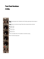
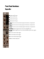
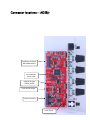
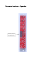
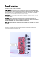
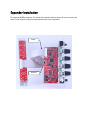
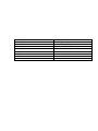
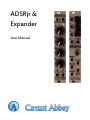
ADSRjr & Expander User Manual ADSRjr Description The ADSRjr is an envelope generator with many features. Standard gate input jack is normalled to the Doepfer bus gate signal. Three time ranges cover times from tiny to huge. Linear or expo curves are jumper selectable. A cycle button creates continuous waves. The expansion module brings out a metric boatload of features: CV control of each segment, trigger button and jack, buttons replace the linear/expo jumpers, end of attach, decay and release outputs, and an inverted output. ADSRjr Features: Gate jack normalled to Doepfer bus gate signal Time range selections: short, medium, long Linear or exponential curve jumper selectable for each segment Cycle button for continuous operation Convenient output jack 4HP, depth=53mm Expansion Features: CV control of each segment Buttons for selecting linear or exponential curves Trigger button and input End of attack, decay, and release outputs Inverted output jack 4HP, depth = 26mm Both modules are 4HP. The ADSRjr module has a maximum 20mA current draw. Front Panel Interface: ADSRjr Gate: Standard gate input. Normalled to the Doepfer gate signal with a jumper to defeat. Time: Button to set the time range. Green=fast, orange=medium, red=slow. A: Attack time. D: Decay time. S: Sustain level. R: Release time. Cycl: Cycle mode button. Puts module in continuous cycling. Out: Convenient output jack. Front Panel Interface: Expander A: Attack time CV input. D: Decay time CV input. S: Sustain level CV input. R: Release time CV input. A Curve: Sets the curve for the attack segment. Out=linear, in=exponential. D Curve: Sets the curve for the decay segment. Out=linear, in=exponential. R Curve: Sets the curve for the release segment. Out=linear, in=exponential. Trig Button: Manual trigger button. Fires off one full ADSR cycle. Trig Jack: Manual trigger button. Fires off one full ADSR cycle for every trigger. EOA: End of attack output trigger. EOD: End of decay output trigger. EOR: End of release output trigger. Inv Out: Inverted output jack. Connector locations -- ADSRjr Expansion connector NO POWER HERE!!! Curve jumpers Pull for expo Doepfer Bus gate disable jumper 5 volt source jumper Power connector Level jumper Connector locations -- Expander Expansion connector NO POWER HERE!!! Setup & Installation To install you ADSRjr, first set up the jumpers. “Time” jumpers: A bit misnamed, as they are used to set the desired curves. An installed jumper sets that segment for exponential, removing the jumper sets the segment for linear. Each segment has its own jumper, and can be set independently from the others. For example, a linear attack and expo decay and release. Ships with all three jumpers installed. Gate jumper: Routes the Doepfer bus gate signal to the gate jack. Remove to disable. Ships with Doepfer bus enabled. +5V jumper: Sets the source of the 5 volts used internally in the module. Ships in the +12V position to derive 5 volts from the +12 volt supply. If your case has the 5 volt rail powered you can move the jumper to the “Buss” position to offload the +12 volt supply. “Pull for 8V”: Another misnomer. Module ships with 0-5V output range. For 0-10V range, remove this jumper. Now you can attach the power cable as shown, making sure the red stripe is in the correct position, and install the module in your case. Install power cable thusly Expander Installation To install you ADSRjr expander, first attach the expander cable as shown. Be sure to remove the three “Time” jumpers as they are replaced by buttons on the expander. Attach Remove Module Width Module Depth Power Connector Power Requirements Input Impedance Output 4HP (20mm) 53mm Standard Doepfer 16 pin ± 12 Volts at 20mA Max 20K Ohms Short circuit protected