1
System A - 100
doepfer
Sampler A-112
1. Introduction
A-112
SAMPLER
MIDI In
MIDI Out
Modus
Man. Trig.
Gate In
Audio IN /
Wave-CV In
CV In
Atten.
Tune
Audio Out
Run
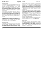
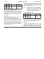
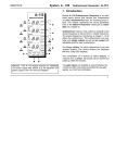
Module A-112 (SAMPLER) is a combination module,
including a voltage controlled 8 bit Sampler and a
voltage controlled Wavetable Oscillator.
The module has the characteristic “grungy“ sound
of the early 8 bit Samplers and is a welcome addition to the A-100’s sound generating capabilities.
But it should not be compared with the polyphonic 16
bit MIDI samplers available on the market.
The module contains an A/D converter (ADC) for
recording the audio signal (8 bit resolution), digital
memory for storage of the the sampled signal, a D/A
converter (DAC) for playback and the control unit.
The memory is divided into two banks (S1, S2) with 64
kbyte each. In wavetable mode each bank is arranged
as 256 pages of 256 bytes.
The memory is non-volatile, i.e. after power-off the
sampling data in the memory is maintained.
1
A-112 Sampler
System A - 100
Sampling mode
In sampling mode the incoming audio signal is sampled with a sampling frequency that is controlled
manually and from the external control voltage
input. The audio signal is converted by the ADC into 8
bit digital data and sequentially written into the memory (memory address 0 ... 65 535). With a sampling
frequency of 32kHz this corresponds to 2 seconds
sampling time.
During playback the sampling data in the memory is
read sequentially (address 0 ... 65535) and converted
into the corresponding audio signal by the DAC. The
sampling frequency in play mode is controlled manually and from the external control voltage input. Playback is stopped if the last memory address (65535) is
reached.
Via MIDI dump the sampling memory can be sent to a
computer for storing the data on hard-disk or any other
storage device. The computer may also transmit
sampling data to the A-112 via MIDI dump.
Wavetable mode
In wavetable mode the memory access is not sequentially but by page. The page number is selected by
an external voltage. This voltage can be may generated manually (e.g. with the manual control voltage
2
doepfer
source A-176) or it may come from any other voltage
source (e.g. LFO, ADSR, Sequencer). Both record and
play take place in a loop whereby the complete page
is always passed through. When reaching the end of a
page the run control determines if a jump to another
page takes place or the loop remains in the same page
- depending upon the voltage controlling the wavetable/page.
Playback with a dynamic control voltage (e.g. ADSR,
LFO, Random, Sequencer, MIDI-to-CV) results in
“sweeping through“ the different pages (Wavetable
principle). If the memory of the A-112 contains suitable wavetables in the 256 pages, the result is a
voltage controlled Wavetable Oscillator with two control voltages: one for the audio frequency (pitch, tune),
one for the wavetable number.
Normally suitable wavetables are generated by a computer and transferred to the A-112 via MIDI-Dump.
Effect mode
Additionally the module offers some effects, like Delay, Reverse Delay and Pitch Shifter. Of course, due
to the 8 bit resolution these effects are not to be
compared however with the results from high-end
effect devices, but should be considered as a free
extra gift for strange sounds.
System A - 100
doepfer
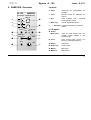
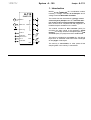
Controls:
2. SAMPLER Overview
A-112
SAMPLER
VC Sampler / Wavetable Osc.
S1
➄
Eff
➅
Dmp
➆
➌
➃
➊
Play
1 Atten. :
Attenuator for Audio/Wave CV
Input !
2 Tune :
Manual control for Sampling frequency
3 Run :
Gate indicator LED / overload
warning during record
4 Man. Trig. :
manual trigger/start button
MIDI Out
S2
Rec
Pit Del Rev
Loop
Wav
➎
MIDI In
➏
Len Norm Frz
Man.
Gate In Trig.
Audio Out
Run
Audio In /
Wave-CV In
Atten.
0
Tune
➋
0
10
5 ... 7 Switches: 3-position switches for mode selection
In / Outputs:
➍
➂
➀
10
CV In
Sampler A-112
➁
! Audio /
Wave-CV In:
Input for audio signal resp. wavetable control voltage in wavetable mode
" CV In :
pitch control input (1V/oct.) for
tuning or sampling frequency
§ Gate In :
Gate input
$ Audio Out :
Audio output
% MIDI In :
MIDI input
& MIDI Out :
MIDI output
3
A-112 Sampler
System A - 100
H
3. Controls
1 Atten.
Control 1 attenuates the level of the voltage at input
!. Depending upon the mode this voltage is the audio
signal (in sampling or effect mode) or the wavetable
control voltage (in wavetable mode).
The tune control 2 is used to adjust the sampling
frequency (during record) or the pitch/tune during
playback (see table below).
Exception: In wavetable record mode one of the 256
pages is selected with the tune control (see following
table). In this case the sampling frequency defaults to
the last frequency that was set prior to switching into
wavetable mode.
page
(appr.)
samplingfreq. [kHz]
tuneposition
page
(appr.)
samplingfreq. [kHz]
0
0
2,0
6
154
18,5
1
26
2,9
7
179
26,5
2
51
4,2
8
205
38,5
3
77
6,1
9
231
56,2
4
103
8,8
10
255
79,4
5
128
12,7
The data in the table are approximate values
4
The voltage generated with the tune control
is internally added to the voltage at input ".
This input is normally used to control the
pitch of the sampler/wavetable oscillator in
play mode with an external control voltage
following the 1V/oct standard (e.g. the A-190
MIDI-to-CV interface).
3 Run
2 Tune
tune
position
doepfer
LED 3 is used for different monitoring purposes
depending upon the mode selected. A description of
the respective function is given in the corresponding
paragraph elsewhere in this manual.
4 Man. Trig.
Button 4 is used to trigger the sampler manually.
Depending upon the mode selected a Trigger or Gate
leads to different actions. A description of the
respective functions is given in the corresponding
paragraph elsewhere in this manual.
H
The manual trigger generated with button 4
and the signal at the gate input § are internally connected, to produce a gate/trigger
signal used for all triggered/gated functions.
System A - 100
doepfer
5
6
Dmp
S1, S2
Play
Rec
Pit
Eff
Del
Rev
7
Function
Loop
not implemented
Norm
Dump a sample
Wav
Dump a wave
Loop
Play a loop
Norm
Play a sample
Wav
Play a wave
Loop
Record a loop
Norm
Record a sample
Wav
Record a wave
Len
Input sample length required
Norm
Pitch Shift with "Freeze"
Len
Input sample length required
Delay with "Freeze"
Len
Input sample length required
Frz.
•
6 Switch
•
7 Switch
With the 3-position switches 4 to 6 the operating
mode is selected. The table on the left lists all possible
modes. The modes are described in the following
paragraphs.
In particular the gate signal (gate input § / manual
trigger 4) controls different functions in the respective
operating modes.
H
Please note that in some modes it is not
sufficient to change the switches position to
exit the mode. In the following description of
the modes you will find detailed information
on how to exit a selected mode.
Delay
Frz.
Norm
5 Switch
Pitch Shift
Frz.
Norm
Sampler A-112
Reverse Delay
Reverse Delay with "Freeze"
5
A-112 Sampler
System A - 100
• Normal record mode
5
S1,
S2
6
7
Rec Norm
Audio / Wave-CV In
Audio signal
Tune / CV
sampling frequency (while
Gate = low)
In this mode an audio signal at audio input 1 is
recorded into one of the 2 memory banks S1 or S2
(depending upon the position of switch 5).
Gate = low :
In this case the pre-listening mode is active (LED 3
is off); the audio signal at input 1 is digitized by the
ADC, re-converted by the DAC and forwarded to audio
output 4 for pre-listening.
The pre-listening mode contains an overload/ clipping function: as soon as the audio signal exceeds a
predefined upper or lower threshold the LED 3 lights
up for a short moment (about 10 ms). During this time
the audio signal is not scanned and the output remains
at the last DAC value. The onset of clipping (i.e.
overload distortion) is immediately audible.
H
6
The sound quality in the pre-listening mode
is very poor. The quality if a signal is recorded and played back is much better!
doepfer
The pre-listening mode is also used to find out and
set the sampling frequency. When record mode is
entered (see below) the last sampling frequency in
pre-listening mode is used.
Gate = high:
When the gate level changes from low to high Record
is triggered and the audio signal is sampled into the
memory bank selected with switch 5. LED 3 is now
on. Recording starts at address 0 and continues until
the last address (65 535) is reached and LED 3 turns
off. If gate turns low before the end of the sampling
memory (address 65 535) is reached the record process stops. You can use this function to sample chosen segments of sound.
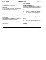
• Normal play mode
5
S1,
S2
6
7
Play Norm
Audio / Wave-CV In
Tune / CV
-------
sampling frequency
In this mode a previously recorded sample in the
sampling memory (S1 or S2, depending upon the
position of switch 5) is played back.
doepfer
System A - 100
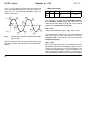
Gate = low:
The module is waiting for gate = high; LED 3 is off
(see fig. 1 - a).
Gate = high:
When the gate level changes from low to high Playback is triggered and the audio signal in the memory
bank is played back. LED 3 is now on. Playback starts
at address 0 and continues until the last address (65
535) is reached and LED 3 turns off. Even if the gate
goes low before the end of the sampling memory is
reached the playback continues (see fig. 1 - b).
Only if the gate goes low and high again before the
end is reached the sample is retriggered, i.e. the
playback starts again at address 0 (see fig. 1 - c).
If the gate is still high when the end of the sample
memory is reached the playback stops (i.e. no loop if
gate remains high). For this purpose the loop mode is
used.
A udio
Out
Sampler A-112
Sample
Gat e
a
b
c
fig. 1: normal play mode
• Loop record mode
5
6
7
Audio / Wave-CV In
S1,
S2
Rec
Loop
audio signal
Tune / CV
sampling frequency (only if
Gate = low)
This mode is very similar to the normal record mode
(see above). The only difference to the normal record mode is that record continues when the end of
the sample memory is reached and the gate level is
still high.
7
A-112 Sampler
System A - 100
In this case the record starts again at the first memory
address. This loop continues (LED 3 on) until gate
turns low.
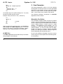
• Loop play mode
5
S1,
S2
6
7
Play Loop
Audio / Wave-CV In
Tune / CV
---------
sampling frequency
In normal play mode the playback stops if the end of
the sample memory is reached. The loop play mode
allows the continuous playback of a pre-defined
section of the sample memory.
doepfer
as long as the gate level remains low (see fig. 2: loop
1).
If gate turns high (see fig. 1 - c) the loop end is
cancelled and the sample playback uses the full range
again (i.e. loop end = end of sample memory, see fig.
2 - d).
If the gate goes low again a new loop end is set (see
fig. 2 - e, loop 2).
To exit loop play mode a short trigger pulse (max.
duration 100 ms) is required (see fig. 2 -f).
A udio
Sample
Out
Gate function:
As long as the gate level is high the sample is played
continuously. When the end of the sample is reached,
playback starts again at the beginning (see fig. 2 - a).
LED 3 is on.
As soon as the gate goes low the present position
within the sample is defined as loop end (see fig. 2 b). Playback starts at the beginning (address 0) and
runs continuously from the beginning to the loop end
8
Gat e
b
a
e
d
Loop 1
fig. 2: Loop play mode
c
f
Loop 2
System A - 100
doepfer
• Wave record mode
Sampler A-112
Gate = high:
5
6
7
Audio / Wave-CV In
Tune / CV
S1,
S2
Rec
Wav
audio signal
sampling frequency (if gate =
low) /
wavetable number
(if gate = high)
In this mode one or more wavetables are recorded
into the memory bank selected.
The number of the wavetable (page) results from the
position of the Tune control 2 and the voltage applied
to the CV input ".
Gate = low :
The pre-listening mode is active (LED 3 is off); the
audio signal at input 1 is digitized by the ADC, reconverted by the DAC and forwarded to audio output
4 for pre-listening.
All functions and controls (overload/clipping, adjustment of sampling frequency ...) are the same as in the
normal record mode (see above).
When the gate goes high record starts (LED 3 is on).
The last sampling frequency while gate was low is
used as the sampling frequency. The wavetable number (page) is derived from the position of the Tune
control 2 and the voltage applied to the CV input ".
The audio input is sampled and 256 bytes are written
into the wavetable memory (page) selected.
When the last byte of the page (i.e. byte no. 256 of the
page) is written record starts again at the first byte of
the page. This process continues (LED 3 on) until the
gate goes low.
The record process stops immediately at the present
position as soon as the gate goes low. You can use
this function to sample chosen segments of sound.
When reaching the last position of the current wavetable page the number of the next page is defined
by the position of the Tune control 2 and the voltage
applied to the CV input " (provided that gate is still
high). Consequently different pages may be selected
during record if the control voltage (e.g. from an
ADSR) or the position of the tune knob is changed .
9
A-112 Sampler
System A - 100
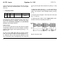
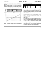
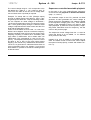
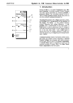
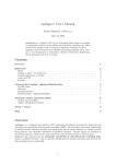
In fig. 3, the CV input is fed from the sine output of a
LFO. The sampling frequency is 32kHz, the LFO frequency 21 Hz. The resulting wavetable pages are
shown in the boxes.
+5 V
243
220
5
6
7
S1,
S2
Play
Wav
Audio / Wave-CV In
Tune / CV
Number of wavepage
sampling frequency
In this mode A-112 works as a wavetable oscillator.
The wavetable number (page) that determines the
sound of the audio output is set by the control voltage
applied to the audio/wave CV input !
128
102
Gate = low:
64
-5 V
8
51
26
The module is waiting for gate = high; LED 3 is off.
0
wave record mode with modulated wavetable
page number
Waves recorded in this way may be played back in the
normal play mode, often leading to some fairly drastic
effects.
10
• Wave play mode
251
2 38
154
fig. 3:
doepfer
The initial sampling frequency (i.e. the first frequency
when gate turns to high, see below) is set. Prelistening mode is also used to find out and set the
sampling frequency.
Gate = high:
When the gate goes high the wavetable number
(audio/wave input) and the sampling frequency (tune
control and CV input) are set, and playback of the
recorded wavetable begins, using the sampling frequency previously set (LED 3 turns on). When the end
of the wavetable is reached the process starts again,
System A - 100
doepfer
i.e. the next wavetable and the next sampling frequency are determined. This continues until the gate
goes low.
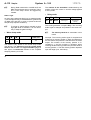
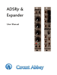
When a dynamic voltage -2.5...+2.5V is used as the
wavetable control voltage (e.g. ADSR output connected to audio/wave input !) wavetable are swept.
memory
bank
Speicherbank
118
Audio In
127
135
Loop
0,40
• Normal dump mode
5
S1,
S2
6
7
Audio / Wave-CV In
Tune / CV
Dmp Norm
In this mode a sample (bank 1 or 2) can be transferred
as a MIDI system exclusive string (SysEx Dump) via
MIDI out &. You can then record this string with a MIDI
computer sequencer or download it using a MIDI dump
program for storage on hard disk or any other storage
device. The sampling frequency is also transferred
within the string.
It is also possible to receive a sample dump via MIDI
input %. The dump is written to the memory bank
selected (S1 or S2).
0,30
0,20
0,10
0,00
Gate = low:
-0,10
-0,20
-0,30
-0,40
fig. 4:
Sampler A-112
wavetable selection with CV voltage applied
to audio/wave input
In this state (LED 3 off) MIDI input % is scanned. As
soon as an incoming sample dump is detected LED
3 turns on and the dump data is written into the
memory bank selected.
If a sample dump request is received via MIDI IN the
sample memory is transferred via MIDI OUT as a
SysEx string. LED 3 turns on as well. Refer to the
description of MIDI input and output in chapter 5.
11
A-112 Sampler
H
System A - 100
During Data transmission via MIDI OUT the
MIDI input and gate are not scanned. Therefore a new dump cannot be triggered by
mistake.
As soon as the gate goes high (e.g. by pressing button
4) the sample memory is transferred as a SysEx dump
via MIDI OUT and LED 3 turns on (same function as
sample dump request via MIDI in).
To trigger a sample dump manually a short
high gate level is sufficient. It is not necessary to keep the gate level high.
S1,
S2
6
Dmp
7
Wav
Audio / Wave-CV In
Tune / CV
wave page number
This mode is very similar to the normal dump mode
(see above). The difference from the normal dump
mode is that the data of a single wavetable (page) of
256 bytes is transferred instead of the complete
sampling memory of a bank.
12
5
6
7
Audio / Wave-CV In
Tune / CV
Eff
Del
Norm
audio signal
sampling frequency
This mode generates a simple delay. The incoming
audio signal is delayed and passed to the audio output.
H
• Wave dump mode
5
The number of the wavetable is determined by the
position of the tune control 2 and the voltage applied
to CV input ".
• Delay mode
Gate = high:
H
doepfer
The memory bank S2 is overwritten in this
mode!
Principle: The incoming audio signal is sampled and
written into a memory position in bank S2. Before this
the old value at this position is transferred to the audio
output. The number of the memory position is increased by 1 and the process is repeated. When
reaching the last memory position the process starts at
memory position 1. The last memory position depends
upon the length (Len, see below).
doepfer
System A - 100
The length of the delay memory is defined by the
parameter Len (see below). The maximum length is
the complete sampling memory (64kbyte = 65536
bytes). With a sampling frequency of 32 kHz this
corresponds to 2 seconds delay time. The actual
delay time is decided by a combination of the length
of the delay memory (Len) and the sampling frequency.
Gate = low:
The module is waiting for gate = high; LED 3 is off.
The initial sampling frequency is set.
Gate = high:
Sampler A-112
A udio
In
A-112
A-138
A-112
A udio
Out
Feedback
fig. 5: Echo
• Reverse delay mode
5
6
7
Audio / Wave-CV In
Tune / CV
Eff
Rev
Norm
audio signal
sampling frequency
The delay mode is started; LED 3 turns on. Retrigger
is active, i.e. a gate transition to low and back to high
starts the delay mode again.
This mode is the same as the delay mode but the
playback of the delayed signal takes place in reverse.
H
H
P
Moving from delay mode directly to delay
with freeze is not possible. To perform this
one has to interrupt the delay mode (switch
5 to S1/S2 or switch 7 to Len) and then
select the desired mode.
By feeding the A-112 output back to its input
one obtains a repeat or echo (see fig 5).
Beware: too much feedback leads to an
avalanche-like effect. In this case the feed
back component has to be reduced.
Memory bank S2 is overwritten in this mode!
Principle: Same as the normal delay mode but writing
into the delay memory is performed forward, and
reading the delay memory is performed backward. As
this is a very simple “bog standard“ algorithm, overlapping effects may occur and lead to interference, glitches or clicks in the audio output signal.
13
A-112 Sampler
H
System A - 100
All functions and controls (sampling frequency, length of delay memory ...) are the
same as in the normal delay mode (see
above).
• Pitch shift mode
5
6
7
Audio / Wave-CV In
Tune / CV
Eff
Pit
Norm
audio signal
sampling frequency
In pitch shift mode the audio input signal is sampled
and played back at the audio output with shifted pitch/
tuning.
H
Memory bank S2 is overwritten in this mode!
Principle: The incoming audio signal is sampled with a
fixed sampling frequency (about 16 kHz) and written
into memory bank S2. Each sample increases the
memory position by 1. Simultaneously the memory is
read out with a sampling frequency that is determined
by the Tune control 2 and the voltage applied to the
CV input ".
If the read frequency is nearly the same as the write
frequency (i.e. about 16 kHz) no pitch shift occurs just a delay depending upon the memory length (Len).
14
doepfer
If read and write frequency differ the audio signal is
read out faster or slower and the pitch shift effect
occurs.
Because of this very simple “bog standard“ algorithm
overlapping effects may occur and lead to interference, glitches or clicks in the audio output signal.
H
All functions and controls (read sampling
frequency, length of delay memory ...) are
the same as in the delay mode (see above).
P
Very interesting sounds can be obtained if
the original audio signal is mixed with the
pitch shifted signal of the A-112 (using a
mixer A-138a/b).
System A - 100
doepfer
• Freeze option
5
6
7
Audio / Wave-CV In
Tune / CV
Eff
Del,
Rev,
Pit
Frz.
audio signal
sampling frequency
The effect modes delay, reverse delay and pitch shift
may also run with the Freeze option.
In this case the audio input is no longer sampled and
the memory data no longer overwritten. Instead, the
frozen memory data are played back. The parameters
memory length (Len) and sampling frequency determine the effect.
Gate control:
The module is waiting for gate = high; LED 3 is off.
The initial sampling frequency is determined.
If only a short gate pulse appears (i.e. gate turns to
high only for a short time and becomes low again) the
effect selected functions without freeze. LED 3 is off.
As soon as gate turns high and remains high the
freeze option of the effect in question is active. LED
3 is on. The data in the memory are “frozen“ as long
as the gate remains high.
Sampler A-112
When gate turns low the freeze option is cancelled
and the module returns to the respective effect without
freeze. To re-activate the freeze option, one simply
has to turn the gate to high.
H
Changing directly to the normal effect without
freeze (permanently) is not possible. To perform this one has to interrupt the freeze
option (switch 5 to S1/S2 or switch 7 to Len)
and select the desired mode after this.
• Effect parameter "Len"
5
6
7
Eff
Del,
Rev,
Pit
Len
Audio / Wave-CV In
Tune / CV
memory length for
the effect in question
In this operation mode the parameter Len is adjusted.
This value determines the length of the sampling
memory in bank S2 used for the effect modes.
Gate = low:
In this state the Tune control 2 adjusts the Len
parameter. The resolution for the length is one page
(256 bytes). The tune knob turned fully to the left (ccw
position 0) corresponds to one page, turned fully to the
15
A-112 Sampler
System A - 100
right (cw position 10) it corresponds to the whole
memory (64 kbyte or 256 pages). During the adjustment of Len with the tune control no external voltage
should be applied to the CV input ".
Gate = high:
As soon as the gate goes high the current position of
the tune control is used to set the Len value.
For the different effect modes the following notes also
apply:
4. In / Outputs
! Audio In / Wave-CV In
At this socket the audio input signal is patched in (i.e.
the signal to be sampled or used for effects). This is a
line level input (+/-2.5V or 5Vss). Note that the audio
signal must be at line level – microphones won’t give
enough output.
H
Delay, Pitch Shift:
The factory setting is 4 kBytes (i.e. 16 pages). This
corresponds to a tune control setting of about 0.5.
Reverse Delay:
The factory setting is 64 kBytes (i.e. 256 pages).
This corresponds to tune control setting 10.
The reverse delay effect seems to go very strange with
tune control settings of about 1.5 down to 0, i.e. the
reverse delay becomes a normal delay, but with extreme distortion.
doepfer
Exception: In wavetable play mode this is
the wavetable control voltage input 2.5...+2.5V (not an audio signal input)!
" CV In
Control voltage input for sampling frequency during record, or pitch/tune during play. This input
follows to the 1V/oct. standard and has 1/4 semitone
resolution.
H
The control voltage applied to CV in " is
internally added to the voltage generated by
the tune control 2.
§ Gate In
At the Gate input § the gate signal is patched in. The
function depends upon the mode selected.
16
System A - 100
doepfer
H The gate signal applied to this socket is internally connected with the signal coming from the
button 4. If either of these is high, the module
gate is high.
Gate In §
high
high
low
low
Man. Trig. 7
high
low
high
low
result. Gate
high
high
high
low
$ Audio Out
Socket $ is the audio output of the A-112.
H
The audio signal from the DAC passes a
simple low-pass filter to suppress the
sampling frequency. It is possible to bypass
this internal filter if a more sophisticated lowpass filter (A-120, A-121, A-122) is used or if
the sampling frequency should not be suppressed for special effects. For this the internal jumper J1 has to be removed.
Sampler A-112
% MIDI In
Socket % is the MIDI input used to receive sample
data (SysEx dump) via MIDI. For this the dump or
wave dump mode has to be selected (see above) and
the gate has to be low.
Moreover a sample dump request or a wave dump
request message can be received by the A-112 in this
mode.
The MIDI SysEx message for a sample dump request has the following structure:
F0
00 20 20
7F
< bank>
F7
Doepfer SysEx-ID
bank number (00 : S1, 01 : S2)
When receiving this message the A-112 transmits at
the MIDI output & a sample dump (LED is on). The
length of the dump is 74.909 bytes altogether. Additionally the current sampling frequency is transmitted.
The SysEx message for a wave dump request has
the following structure:
17
A-112 Sampler
System A - 100
F0
00 20 20 Doepfer SysEx-ID
7D
< Wave-Nr., Bit 7 - 1 >
< Wave-Nr., Bit 0 >
F7
As the data range in a SysEx message is 0...127 (7 bit)
the wave number requires 2 bytes.
Example: Dump of wave no. 201 ("11001001"):
F0
00 20 20
7D
64
01
F7
5. User Examples
The obvious application of the A-112 is the sampling
and playback of external sounds or sounds generated
with other A-100 modules. On top of this the module
opens up a huge number of sound experiment possibilities – far too many to be covered in this manual.
The following examples concentrate on wavetable
applications of the module.
Wavetable Oscillation
"110100"
"1"
When it receives this message the A-112 transmits a
wave dump at the MIDI output & (LED is on). The
length of the dump is 305 Bytes altogether. Additionally the current sampling frequency is transmitted.
& MIDI Out
The MIDI output & transmits MIDI dump information
during sample or wave dumps.
18
doepfer
The wavetable oscillator feature and the loop feature
of the A-112 have already been described in chapter 3.
Smooth sequencing of the wavetables with an external
control voltage requires a certain amount of subtle
intuition - and additional A-100 modules - as it is
necessary to control the offset and amplitude of the
voltage applied. You do then also have the ability,
though, of selecting a specific starting wavetable
(offset) and starting the up/down sweep through the
waves (amplitude) at this particular point.
For the most effective wavetable control we recommend using the A-129/3 (attenuator and offset generator, see below).
doepfer
System A - 100
The control voltage range 0...+5V corresponds to the
256 tables (0V = table no. 1, +5V = table no. 256). To
move from one table to the next one a voltage difference of about 0.02 V (5V/256) is required.
Example: To sweep with an LFO (Triangle output)
through 64 tables starting with table no. 96 (i.e. passing through the tables 64...128) the following conditions are required: An offset voltage of 96*5V/256 =
1.875V and an attenuation of the LFO signal to 64*5V/
256 = 1.25V (peak-to-peak). Using a A-129/3 the offset
voltage is adjusted with the offset control and the LFO
level with the attenuator control.
If each of the 64 tables are to be used - i.e. none of the
tables is to be skipped - there is a maximum frequency
that the controlling signal (LFO) must not exceed. If the
sampling frequency is 32kHz each wavetable (256
byte) takes 8 milliseconds. All 64 tables take 512
milliseconds. This corresponds to 1.95 Hz LFO frequency. Consequently the frequency of the LFO must
be about 2 Hz or less to play each table without
skipping. This sounds very mathematical and theoretical but it is a good idea to understand these facts as
some unforeseen things may happen if one ignores
these details. In practice of course the resulting sound
is all that counts.
Sampler A-112
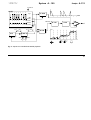
Sequencer-controlled wavetable playback
In the patch in fig. 6 the Analog/Trigger Sequencer
A-155 controls the playback of different wavetables
(step 1, 4, 5 and 7).
The sawtooth output of the LFO, patched via offset
generator A-129/3 generates the control voltage to
sweep through the wavetables. This voltage is added
to the sequencer voltage (post out 2). Thus different
ranges of the wavetable memory are used for each
step (displayed by different sound symbols). Regarding offset, attenuation and LFO frequency, see the
notes on the previous page.
The sequencer control voltage Post Out 1 is used to
control the decay of an VC-ADSR, i.e. for different
decay times for each step.
Instead of an LFO an ADSR or VC-ADSR may be
used. The attack control is used in this case to adjust
the speed of sweep (decay, sustain and release control = 0).
19
A-112 Sampler
System A - 100
doepfer
Wavetable playback of a normal sample
Suggestions for sound experiments:
Very interesting sounds can be obtained if a normal
sample is played back in wavetable mode - especially
if human voice is recorded.
During normal sample playback the sample length
depends upon pitch and the so-called Mickey Mouse
effect occurs.
• If the slope of the voltage controlling the wavetable
is running backwards (e.g. a falling sawtooth) sampled words seem to be spoken backwards (sort of).
If the wavetable mode is used the sample length
depends only upon the slope of the controlling voltage
(e.g. sawtooth) but not upon the pitch. This is adjusted
independently with the tune control and pitch CV.
• Using a random or S&H voltage for controlling the
wavetables leads to the basics of what is often
referred to as granular synthesis.
• By selective scanning of a spoken sample one may
obtain voice or vowel loops.
For the above suggestions it is important that the
period of the sampled sound fits almost exactly into the
space allotted to each wavetable (256 Bytes). If the
result is not satisfactory another record sampling frequency should be used until the desired sound is
obtained.
20
System A - 100
doepfer
Sampler A-112
Cloc k
A-155
1
2
3
4
5
6
7
8
Trig. 1
VC-ADSR
Clock
CV D
Gat e
Po st Out 1
S & H Ctrl. 1
Wave- CV In
A-112
Po st Out 2
VCF
VCA
S & H Ctrl. 2
0V
LFO
Ret rig. In
0V
A-130
+5 V
A-129 /3
Atten.
Off set
00 fig. 6: sequencer-controlled wavetable playback
21
A-112 Sampler
System A - 100
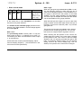
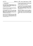
6. A-112 Sample Dump Loader
The A-112 MIDI interface enables the transfer of sample and wave data from and to the device using MIDI
SysEx strings. For that purpose a standard MIDI sequencer may be used.
In addition we include a 3 1/2“ floppy disk containing a
A-112 sample dump loader software for PC.
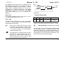
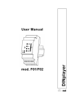
Version 1.2 of this software (see fig. 7) enables bidirectional transfer between A-112 and the PC. Samples and waves can be organized and stored on the
storage device (e.g. hard disk) of a PC. In the PC each
sample or wave can be assigned any name (DOS
convention, i.e. max. 8 characters) and stored as a
WAV file (8 bit mono). The A-112 format is automatically converted into the WAV format.
Conversely, any WAV file can be transferred to the
A-112. The program reads any WAV file in 8, 12 or 16
bit mono or stereo formats. Stereo WAV files are
converted to mono before transfer to the A-112.
22
doepfer
The WAV file format opens up a wide pool of sounds
for use with the A-112. You may try out Windows system sounds or modifying sounds with a sample editor
program and then re-loading back into to the A-112.
For the next version of the sample dump loader program we are planning to include the ability to generate
sample dump MIDI files.
H
The latest version of the sample dump
loader can be found on our internet homepage (http://www.doepfer.com) for free
download.
doepfer
System A - 100
Sampler A-112
fig. 7: A-112 sample dump loader
23
A-112 Sampler
System A - 100
doepfer
7. Patch-Sheet
The following diagrams of the module can help you
recall your own Patches. They’re designed so that a
complete 19” rack of modules will fit onto an A4 sheet
of paper.
A-112
SAMPLER
VC Sampler / Wavetable Osc.
S1
Eff
Dmp
Play
MIDI Out
Rec
Pit Del Rev
Loop
Wav
Make multiple copies of your composite diagram, to
use for remembering good patches and set-ups.
Audio In /
Wave-CV In
SAMPLER
Play
MIDI Out
S2
Rec
Pit Del Rev
Loop
Wav
MIDI In
Len Norm Frz
Len Norm Frz
Man.
Gate In Trig.
Audio Out
Run
Atten.
0
24
Dmp
MIDI In
10
Audio Out
Run
Audio In /
Wave-CV In
Atten.
0
Tune
0
Man.
Gate In Trig.
10
CV In
• Draw in patchleads with coloured pens
• Draw or write control settings in the little
white circles
S1
Eff
S2
Photocopy this page, and cut out the pictures of this
and your other modules. You can then stick them onto
another piece of paper, and create a diagram of your
own system.
P
A-112
VC Sampler / Wavetable Osc.
10
CV In
Tune
0
10