1
DSCUSB Standard Manual
Standard level user documentation.
Contents
Chapter 1 Introduction ............................................................................................................... 2
Overview ............................................................................................................................. 2
Manual Scope ....................................................................................................................... 2
LED Status Indication.............................................................................................................. 2
Chapter 2 Getting Started ........................................................................................................... 3
Communications Interface Information ....................................................................................... 3
DSC Toolkit .......................................................................................................................... 3
What Can The Toolkit Do? ...................................................................................................... 3
Installing DSC Toolkit ............................................................................................................ 3
Connecting the Module to the Computer ..................................................................................... 4
Using the Found New Hardware Wizard ...................................................................................... 4
Using the Software ............................................................................................................... 5
Information Page .............................................................................................................. 6
Home Page ..................................................................................................................... 8
Save and Restore Page ....................................................................................................... 9
Trend Chart Page ............................................................................................................. 10
Logging Page .................................................................................................................. 12
Data Rates and Filter Page ................................................................................................. 14
Calibration Page .............................................................................................................. 17
Calibration .................................................................................................................. 18
Auto Calibration ........................................................................................................ 18
Table Calibration ....................................................................................................... 18
Simple Unit Conversion ................................................................................................ 19
Shunt calibration........................................................................................................ 20
System Zero ................................................................................................................ 20
Limits ........................................................................................................................ 21
Units ......................................................................................................................... 21
Advanced Calibration Page ................................................................................................. 22
Chapter 3 Installation ............................................................................................................... 23
Identifying Strain Gauge Connections ........................................................................................ 23
9 way D Connector Pin-outs ................................................................................................... 23
4-wire load cell .................................................................................................................. 23
6-wire load cell .................................................................................................................. 23
Temperature Sensor (Optional) .............................................................................................. 24
Chapter 4 Specifications ........................................................................................................... 25
Technical Specifications ......................................................................................................... 25
Dimensions & Mounting .......................................................................................................... 26
External Dimensions ......................................................................................................... 26
LED Position ................................................................................................................... 26
Mounting Holes ............................................................................................................... 26
DIN Rail Mounting (Optional Kit) ........................................................................................... 27
Cable Clearance .............................................................................................................. 27
Cable Retention .............................................................................................................. 28
Environmental Approvals .......................................................................................................... 28
CE Approvals ..................................................................................................................... 28
Warranty ............................................................................................................................... 28
1
Mantracourt Electronics Limited - DSCUSB Standard Manual
Chapter 1 Introduction
This chapter provides an introduction to the DSCUSB products, describing the product range and main features.
Overview
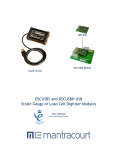
The DSCUSB product is a compact, high-precision Strain Gauge Converter; converting a strain gauge sensor input
to a digital output and is connected to a PC via a USB port. They allow high precision measurements to be made
and communicated directly to a PC and is aimed at applications which require high-accuracy measurement
repeatability. With the appropriate drivers installed, the DSCUSB appears as a virtual serial port to the PC.
Simply by plugging the device into a PC, data can be extracted from most strain gauge bridge input sensors and
acquired by software which allows data manipulation removing the need for amplifiers, filters & multimeters.
Free-standing module fitted with 9-way ‘D’ type socket for load cell and optional temperature sensor
connections.
Micro USB socket accepts a USB lead with type ’A’ connector at the PC end.
Manual Scope
This manual covers only the Standard level of functionality and calibration and assumes the operator is going to
use the DSC Toolkit as a means of configuration and to extract data from the module.
The DSCUSB may have already been connected to a loadcell and calibrated in which case this is the only manual
you will need to refer to.
A separate manual covers the Advanced functionality which includes loadcell profiling calibration, information on
writing your own communication software and advice on OEM production techniques.
If you have purchased this module and intend to connect it to a loadcell and perform linearization or temperature
compensation then you will need to refer to the DSCUSB Advanced Manual.
Please note that your DSCUSB module may have had the advanced features locked and if this is the case then you
will only be able to use the features documented in this manual.
LED Status Indication
The module indicates status via a flashing red Healthy LED.
With no load cell connected The LED of the DCell or DSC should flash OFF for 100ms every 500ms (LED will be ON
but flash off for a tenth of a second every half a second).
If a load cell is connected and there are no errors then the LED will Flash ON for 100mS then OFF every 500ms
(LED will be off but flash on for a tenth of a second every half a second).
Mantracourt Electronics Limited - DSCUSB Standard Manual
2
Chapter 2 Getting Started
Please ensure that software is installed before connecting the module to your PC
This chapter explains how to connect to a DSCUSB for the first time and how to get it working.
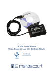
Communications Interface Information
DSCUSB modules can connect to a PC by plugging into a USB port and do not require an external power supply as
they appear as a ‘single unit load’ i.e. they draw <100mA.
Appropriate drivers must be installed which are bundled with the DSC Toolkit. These create a virtual serial port
allowing the DSCUSB to appear to the PC as a normal COM port device.
DSC Toolkit
The DSC Toolkit is a simple configuration tool designed specifically for configuring DSCUSB modules.
This toolkit allows configuration, calibration, logging and parameter management of the modules.
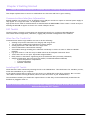
What Can The Toolkit Do?
Communications with a single module at a time to do the following:
• Viewing of input with enunciators for integrity and range errors.
• Two point auto calibration by application of known weight.
• Setting System Zero and under and over range limits.
• Select measurement rate and filter settings.
• Save module settings including user calibration and ability to restore to same or different USB DSC
modules.
• Log input value to a CSV file at up to 100Hz which can be analysed in Microsoft Excel.
• Trend chart view of live input. Exportable image and data.
• Easily switch to alternative engineering units (If module has been previously calibrated)
• Advanced Calibration (Not covered in this manual, see DSCUSB Advanced Manual)
o 5 point temperature compensation
o 7 point linearization
o Lockable calibration
Installing DSC Toolkit
Install the DSC Toolkit software by inserting the CD in the CD ROM drive. This should start the ‘AutoRun’ process,
unless this is disabled on your computer.
(If the install program does not start of its own accord, run SETUP.EXE on the CD by selecting ‘Run’ from the
‘Start Menu’ and then entering D:\SETUP, where D is the drive letter of your CD-ROM drive).
The installation software pre-installs the required drivers so that they can be automatically found when the
hardware is plugged in later on.
After the software has been installed please connect the module and see the next section
before running the DSC Toolkit
3
Mantracourt Electronics Limited - DSCUSB Standard Manual
Connecting the Module to the Computer
Connect to a spare USB port on the Windows PC using the cable provided with the module.
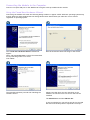
Using the Found New Hardware Wizard
Connecting the module will cause the following dialog windows to appear. NOTE: Different operating systems may
present different dialog windows but the dialogs shown below should allow you make the correct choices
regardless of operating system.
The ‘Found New Hardware Wizard’ should now
appear.
Select ‘No, not at this time’ so that the wizard does
not try searching online for a driver.
Click ‘Next’.
Now the wizard will start searching for the drivers.
The wizard should then proceed with installing the
software drivers.
Please note that there are two interfaces to the
hardware so that there are two drivers that will be
installed
The USB DSC Port and the USB DSC Bus.
So the next dialog box you will see will be for the USB
DSC Port and the steps will be repeated from step 2.
Mantracourt Electronics Limited - DSCUSB Standard Manual
4
Using the Software
You can now launch the DSC Toolkit software.
The DSC Toolkit automatically detects the connected DSCUSB modules.
If there is only one DSCUSB connected when you launch the DSC Toolkit it will be automatically selected and the
Information Page will be displayed.
If multiple modules are detected you will be presented with a list to choose one from on the Home Page.
To connect to a module just click on one in the list to highlight it and click the ‘Connect’ button (Or just double
click the module in the list).
You will then see the Information page.
If no modules have been detected the ‘No modules detected’ message appears. Click the ‘OK’ button and the
‘Connect’ button changes to ‘Demo’. If you click the ‘Demo’ button you can navigate through the software
application with no module attached.
5
Mantracourt Electronics Limited - DSCUSB Standard Manual
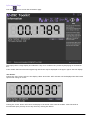
Information Page
Click the
icon to access the Information page.
This simply shows a large display and indicates if any error conditions are present by displaying an information
box.
If the module has been allocated engineering units these may be displayed in the upper right of the LCD display.
‘Net’ Button
Clicking the ‘Net’ button will zero the display. When zeroed the ‘NET’ indicator will be displayed and the button
caption will change to ‘Gross’
Clicking the ‘Gross’ button will return the display to the actual value from the module. Note that with an
unconnected input you may not see any effect by clicking this button.
Mantracourt Electronics Limited - DSCUSB Standard Manual
6
‘Format’ Button
Clicking the ‘Format’ button allows you to select a new format for the displayed value. By using this you can hide
unwanted decimal places.
Just click the required display format in the list.
If any errors are detected these will be shown under the main display. The following screenshot shows an
Integrity error present.
The error box will disappear once the error is no longer present.
7
Mantracourt Electronics Limited - DSCUSB Standard Manual
Home Page
To select a different module just click the Home icon
You can then select a different module or plug in a different module. If you change the connected modules click
the ‘Detect’ button to re-list the modules. Then select the required module from the list.
Mantracourt Electronics Limited - DSCUSB Standard Manual
8
Save and Restore Page
Click on the
icon to open the Save & Restore page.
Clicking the ‘Save’ buttons will allow you to specify a file to which the configuration of the connected module is
written.
Once saved this file can be selected, after clicking the ‘Restore’ button, and the settings restored to the same
module or to another module.
9
Mantracourt Electronics Limited - DSCUSB Standard Manual
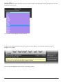
Trend Chart Page
Click on the
icon to open the Trend Chart page.
Data will be read from the module at the Measurement Rate (up to a maximum rate of 100Hz) and added to the
trend chart. You can see the current rate at which data is added at the top right of the chart.
The Measurement Rate can be selected in the Data Rates and Filter page by clicking
.
The chart Y axis is auto scaling but you can select the view into a stored history of 10,000 data points. Just drag
the handles of the slider control under the chart to define the start and end point of the view.
The date and time of the first and last point on the chart are displayed in the lower left and right area under the
chart By clicking in the chart you can display a cursor and the date and time at the point of the cursor, also the
data point value will be displayed underneath the chart.
to the left of the view control will pause the chart. This will stop data being
Clicking the Pause button
added to the chart. Please note that data will also cease to be added to the chart if you switch to another page
by clicking any of the icons on the toolbar.
Mantracourt Electronics Limited - DSCUSB Standard Manual
10
Right clicking the chart will display a pop-up menu allowing the following
Copy Chart Image
A graphic image of the chart will be copied to the clipboard.
Copy Chart Data
All the data points in the chart will be copied to the clipboard in a suitable format to be pasted into Microsoft
Excel and many other applications. The columns will be separated with Tab characters and each line terminated
with a carriage return.
This may take a few seconds to copy to the clipboard.
Clear Chart
You will be asked to confirm this action and if accepted the chart will be cleared of all data.
11
Mantracourt Electronics Limited - DSCUSB Standard Manual
Logging Page
Click on the
icon to open the Logging page.
The toolkit allows you to log data to a CSV (Comma Separated Value) file. This file will open in MS Excel when
double clicked.
Log Interval
Choose a Log Interval in milliseconds between 10 and 32000. 10mS will enable a log at 100Hz.
Log File
Select a file to log to. Note that each time the log starts it will erase any data already in the file.
Start
Clicking this button will start the log.
Stop
Clicking this button will stop the log.
View
When a log has just been stopped this button will launch the application associated with CSV files.
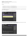
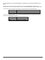
The format of the log file is as follows:
DateTime, Elapsed, Value
Where:
Mantracourt Electronics Limited - DSCUSB Standard Manual
12
DateTime is the date and time in long format
Elapsed is the time elapsed in milliseconds since the start of the log
Value is the numeric value logged
Example
08/06/2009
08/06/2009
08/06/2009
08/06/2009
15:41:08,0,-3.25300008989871E-03
15:41:08,10,-3.25300008989871E-03
15:41:08,43,-3.25300008989871E-03
15:41:08,60,-3.25300008989871E-03
If the measurement rate of the module is less than the rate at which you have chosen to log you will be informed
with a message as shown below.
Either reduce the Log Interval or reduce the Measurement Rate.
Once the logging starts the actual achieved log rate will be displayed at the bottom of the window. This is useful
for diagnostics such as when a heavily burdened PC is slowing the log rate.
13
Mantracourt Electronics Limited - DSCUSB Standard Manual
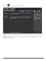
Data Rates and Filter Page
Click on the
icon to open the Data Rates & Filter page.
This page allows you to select the measurement rate and filtering characteristics.
The measurement rate affects the noise free resolution which is indicated at the bottom of the page.
The filter level and filter steps affect the frequency response of the input which is indicated at the bottom of the
page.
The Dynamic filter is basically a recursive filter and therefore behaves like an electronic ‘RC’ circuit. It has two
user settings, a level set in the calibrated engineering units and the maximum number of steps (up to 255).
Instead of outputting every new value, a fraction of the difference between the new input value and the current
filtered value is added to the current filtered value to produce the filtering action.
If this difference is less than the value set in the Filter Level then the fractional amount added each time is
decremented until it reaches the minimum level set by FFST i.e. FFST is the limit of the divisor.
e.g. if Filter Steps = 10 the fractional part of the difference between the new value and the current filtered
value will be added to the current filtered value.
If a rapidly changing or step input occurs and the difference between the new input value and the current filtered
value is greater than the value set in Filter Level then the output of the filter will be made equal to the new
input reading i.e. the fractional amount of the new reading added to the current reading is reset to 1.
This allows the Filter to respond rapidly to fast moving input signals.
When a step change occurs which does not exceed Filter Level, the new filtered value is calculated as follows:
Mantracourt Electronics Limited - DSCUSB Standard Manual
14
New Filter Output value = Current Filter Output Value + ((Input Value - Current Filter Output Value) / Filter
Steps)
The time taken to reach 63% of a step change input (which is less than Filter Level) is dependant on the
frequency at which values are passed to the dynamic filter, set in Measurement Rate, multiplied by Filter Steps.
The table below gives an indication of the response to a step input which is less than Filter Level.
% Of Final Value
63%
99%
99.9%
Time To settle
Measurement Rate * Filter Steps
Measurement Rate * Filter Steps * 5
Measurement Rate * Filter Steps * 7
For example, If Measurement Rate is set to 100Hz = 0.01s and Filter Steps is set to 30 then the time taken to
reach a % of step change value is as follows.
% Of Final Value
63%
99%
99.9%
15
Time To settle
0.01 x 30 = 0.3 seconds
0.01 x 30 x 5 = 1.5 seconds
0.01 x 30 x 7 = 2.1 seconds
Mantracourt Electronics Limited - DSCUSB Standard Manual
The following table shows the number of updates ‘x Filter StepsT’ and the ‘% Error’ that the Filtered Output value
will differ from the constant Input Value.
x FFST
% Error
x FFST
% Error
1
36.78794412
11
0.00167017
2
13.53352832
12
0.00061442
3
4.97870684
13
0.00022603
4
1.83156389
14
0.00008315
5
0.67379470
15
0.00003059
6
0.24787522
16
0.00001125
7
0.09118820
17
0.00000414
8
0.03354626
18
0.00000152
9
0.01234098
19
0.00000056
10
0.00453999
20
0.00000021
Remember: if the step change in mV/V is greater than the value set in Filter Level then:
New Filter Output value = New Input Value i.e. the output jumps to the new input value and the internal
working value of Filter Steps is reset to 1. This is then incremented each update (set by Measurement Rate) until
it reaches the user set value of Filter Steps.
The filter can be disabled by entering zero for Filter Steps.
Note: The Filter Level is stored internally in the module in mV/V and is only presented to the operator via the
software as calibrated engineering units to make it easier. Therefore if the calibration is changed the displayed
Filter Level will change to reflect the new engineering units.
Mantracourt Electronics Limited - DSCUSB Standard Manual
16
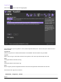
Calibration Page
Click on the
icon to open the Calibration page.
This page allows you to calibrate the module using various methods, set limits, perform system zero and set units
description.
The page is separated by tabbed sections. Click in a tab to change sections.
Reset user calibration – Click the ‘Reset’ button to remove any custom calibration you have applied.
If the DSC module supports it the date of the last change to calibration settings will be displayed.
17
Mantracourt Electronics Limited - DSCUSB Standard Manual
Calibration
Auto Calibration
The automatic calibration requires that you apply two known (ascending) weight in sequence. Just enter the
required engineering unit value for the two weights in the fields marked 1 and 2.
Next, apply the low weight and allow a settle time. Click the ‘Acquire’ button then apply the high weight. After
another settle time click the second ‘Acquire’ button and the calibration is complete.
Table Calibration
This option lets you calibrate direct from the loadcell manufacturers certificate without having to apply weights
to the input.
Choose 2 points from the loadcell certificate and enter the mV/V values and the weights on the certificate (or
convert the certificate weight to any other engineering unit of your choice) click the ‘Calibrate’ button and the
calibration is complete.
Mantracourt Electronics Limited - DSCUSB Standard Manual
18
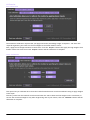
Simple Unit Conversion
This tab will only be enabled if the module has been calibrated in the Advanced Calibration section.
If the Toolkit then recognises the calibrated units (In the example above it is kg) then you can click the box next
to ‘Convert Output To Selected Units’ and you will be presented with a list of units that you can automatically
convert to.
Select the required units, click OK then click the ‘Convert’ button. The Toolkit will then alter the user calibration
to provide the output in the selected engineering units.
19
Mantracourt Electronics Limited - DSCUSB Standard Manual
Shunt calibration
Click the ‘Turn On’ / ‘Turn Off’ button to toggle the shunt calibration output. The shunt cal internally connects a
resistor across the strain gauge bridge. This causes a change in value that can be seen on the Information page
.
By recording the change in value after calibration or installation the system can be verified at a later date by
noting the change caused by turning on shunt cal again.
System Zero
To remove the current weight on all subsequent readings click the ‘Zero’ button. Click the ‘Remove’ button to
return to displaying the actual weight applied. This system zero is stored in the module and remains through
power cycling.
Mantracourt Electronics Limited - DSCUSB Standard Manual
20
Limits
Here you can set limits below and above which the warning indicators will be displayed on the Information Page.
Units
Here you can override any descriptive units that will be displayed on the home page and various other pages.
This does not affect the calibration of the module.
You would use this feature to either add custom units to display after your own calibration or to remove the units
provided by your supplier or those automatically set after performing a ‘Simple Unit Conversion’.
21
Mantracourt Electronics Limited - DSCUSB Standard Manual
Advanced Calibration Page
Click on the
icon to open the Advanced Calibration page. The icon will appear like this when the module
has not had the Advanced Calibration locked out. A message will appear asking if you are sure you want to enter
this advanced level of the software.
You must refer to the DSCUSB Advanced Manual for information regarding the Advanced Calibration pages.
If the module has been protected the icon will appear greyed out
access the Advanced Calibration page.
and you will have to enter a passcode to
You must refer to the DSCUSB Advanced Manual for information regarding the Advanced Calibration pages.
Mantracourt Electronics Limited - DSCUSB Standard Manual
22
Chapter 3 Installation
This chapter gives detailed information on integrating the DSCUSB into a production system – including mounting,
protection, adjustments, wiring and electrical requirements.
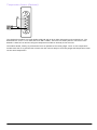
Identifying Strain Gauge Connections
9 way D Connector Pin-outs
4-wire load cell
6-wire load cell
23
Mantracourt Electronics Limited - DSCUSB Standard Manual
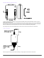
Temperature Sensor (Optional)
The temperature module is a small double sided PCB with an 8 pin SOIC integrated circuit mounted to it. The
dimensions are 10.5 x 7.6 x 2.5mm (0.413 x 0.299 x 0.098”). There are two solder pads for connection to the
DSCUSB. A 2mm hole is used for fixing the temperature module to the body of the load cell.
The module should, ideally, be positioned as close as possible to the strain gauges. The IC on the temperature
module must also be in good thermal contact with the load cell body so the strain gauges and temperature sensor
see the same temperature.
Mantracourt Electronics Limited - DSCUSB Standard Manual
24
Chapter 4 Specifications
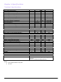
Technical Specifications
Parameter
Strain Gauge Measurement
Strain Gauge Excitation Voltage
Strain Gauge Drive Capability
Strain Gauge Sensitivity
Offset Temperature Stability
Gain Temperature Stability
Offset Stability with Time
Gain Stability with Time
Non Linearity before Linearization
Internal Resolution
Resolution @ 1Hz readings (Noise stable) over 100s
Resolution @ 10Hz readings (Noise stable) over 100s
Resolution @ 100Hz readings (Noise stable) over 100s
Signal Filter
Min
Typical
Max
Units
4 Wire
4. 5
5
5.25
VDC
80
5000
Ohms
-3
2.5
3
mV/V
1
4
ppm/°C
3
5
ppm/°C
20
90
ppm of FR (1)
30
ppm of FR (2)
5
25
ppm of FR
16 Million
Counts/divs
200,000
Counts/divs
120,000
Counts/divs
50,000
Counts/divs
Dynamic recursive type user programmable
Electrical
Power Supply voltage
Power Supply current (350 Ohm Bridge)
Min
4.25
Typical
5
68
Max
5.5
75
Units
V dc
mA
Data transmission
Data transmission rate
Output cable length
Min
Typical
115.200
Max
Units
kbps
m
Optional Temperature Resolution
Temperature Measurement Resolution
Temperature Measurement Accuracy (-10 to 85)
Temperature Measurement Accuracy (-55 to 125)
Temperature update Speed
Min
Typical
0.0625
0.5
2.0
5
Max
Environmental
Operating temperature range
Storage temperature
Humidity
Protection
Min
-40
-40
0
Typical
Max
+85
+85
95
IP50
Dimensions
Cased version
Notes.
1. From original offset at any time
2. 1st Year
25
Mantracourt Electronics Limited - DSCUSB Standard Manual
5
Units
°C
°C
°C
Seconds
Units
°C
°C
%RH
70.5 x 51 x 20mm excluding 9-way ‘D’ type socket
connector.
74.5 x 51 x 20mm including connector.
Dimensions & Mounting
The following diagrams show the case dimensions and mounting holes and optional DIN rail mounting kit.
External Dimensions
LED Position
Mounting Holes
Mantracourt Electronics Limited - DSCUSB Standard Manual
26
DIN Rail Mounting (Optional Kit)
A DIN rail mounting kit is available for top hat DIN rail EN 50022. Optional part DSCUSB-DIN consists of a pair of
screws and two DIN rail clips.
Remove the two screws on the rear of the DSCUSB case and replace with the longer screws from the DSCUSB-DIN
kit. These longer screws secure the din rail clips which sit in the rectangular depressions around the screw holes.
NOTE: You may want to remove and replace one screw at a time to avoid the case coming apart.
Once fitted the top face of the DSCUSB will be 31.4mm from the surface that the DIN rail is mounted on.
Cable Clearance
These are typical clearances but smaller mouldings or using a tighter cable radius can reduce this.
27
Mantracourt Electronics Limited - DSCUSB Standard Manual
Cable Retention
The 9 way ‘D’ socket can accept a mating plug that has screw retention functionality.
The micro USB socket does not have any form of cable retention and this must be taken into account if mounting
the DSCUSB to ensure that the cable cannot disengage accidentally or through vibration.
Environmental Approvals
CE Approvals
European EMC Directive
2004/108/EC
BS EN 61326-1:2006
BS EN 61326-2-3:2006
Output shall not exceed the sum of uncertainties when subjected to an electric field of 10V/m over the frequency
range 80 to 600MHz
Warranty
All DSC products from Mantracourt Electronics Ltd., ('Mantracourt') are warranted against defective material and workmanship for a period of
(3) three years from the date of dispatch.
If the 'Mantracourt' product you purchase appears to have a defect in material or workmanship or fails during normal use within the period,
please contact your Distributor, who will assist you in resolving the problem. If it is necessary to return the product to 'Mantracourt' please
include a note stating name, company, address, phone number and a detailed description of the problem. Also, please indicate if it is a
warranty repair.
The sender is responsible for shipping charges, freight insurance and proper packaging to prevent breakage in transit.
'Mantracourt' warranty does not apply to defects resulting from action of the buyer such as mishandling, improper interfacing, operation
outside of design limits, improper repair or unauthorised modification.
No other warranties are expressed or implied. 'Mantracourt' specifically disclaims any implied warranties of merchantability or fitness for a
specific purpose. The remedies outlined above are the buyer’s only remedies. 'Mantracourt' will not be liable for direct, indirect, special,
incidental or consequential damages whether based on the contract, tort or other legal theory.
Any corrective maintenance required after the warranty period should be performed by 'Mantracourt' approved personnel only.
In the interests of continued product development, Mantracourt Electronics Limited reserves the right to alter product specifications
without prior notice.
Code No. 517-933
Mantracourt Electronics Limited - DSCUSB Standard Manual
Issue 1.1
11.04.14
28
Distribuidor
Brasil e América do Sul
C O N TA T O
Ender eço
Rua Sete de Setembro, 2671 - C entro
13560-181 - São C arlos - SP - Brasil
Telefone
+ 55 (16) 3371-0112
Metrolog Controles de Medição
Fax
+ 55 (16) 3372-7800
Inter net
www.metrolog.net
metrolog @metrolog.net
www.metrolog.net / mantracourt.com
[email protected]
tel +55 (16) 3371-0112