1
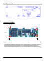
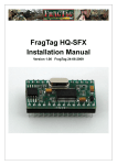
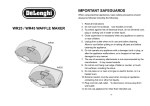
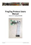
FragTag Odin Users Manual Version 3.30 FragTag 27-02-2012 © FragTag 2012 FragTag Odin Users Manual Copyright Notice FragTag Odin User Manual Copyright 2005,2006,2007,2008, 2009, 2010, 2011, 2012 FragTag All rights reserved. No part of this work may be reproduced in any form or by any means – graphic, electronic, or mechanical, including photocopying, recording, taping, or information storage and retrieval systems – without the written permission of the publisher. Products that are referred to in this document may be either trademarks and/or registered trademarks of the respective owners. The publisher and the author make no claim to these trademarks. While every precaution has been taken in the preparation of this document, the publisher and the author assume no responsibility for errors or omissions, or for damages resulting from the use of information contained in this document or from the use of programs and source code that may accompany it. In no event shall the publisher and the author be liable for any loss of profit or any other commercial damage caused or alleged to have been caused directly or indirectly by this document. Feb 2012 Melbourne, Australia. TERMS FragTag products are protected by both Australian Copyright Law and international copyright treaties. You may not separately publish, market, distribute, sell or sublicense, for fee or no fee, the Licensed Product or any part thereof. FragTag will endeavour to provide free access to software updates to all purchased products that are still currently in development. The distribution method of these updates is at the sole discretion of FragTag, and for security reasons product updates may involve returning electronic components to FragTag or a licensed distributor. In this instance return postage costs may be payable by the purchaser. WARRANTY FragTag warrants that your purchased product will perform substantially in accordance with the provided documentation for a period of twelve (12) months from the date of receipt. In the event of deviations in the product, FragTag will make a reasonable effort to bring the product into conformance with the documentation to provide you with a corrected version as soon as possible. This warranty is void if the product failure has resulted from abuse, accident, incorrect wiring, misapplication, incorrect mounting causing short circuits, or moisture ingress. It is the responsibility of the purchaser to mount the products in such a manner as to protect it from moisture. FragTag's liability is limited to refund of the money paid for the product, and in no event will FragTag be liable for any indirect or consequential damages that may arise (including damages for loss of business profits, business information, or other pecuniary losses). © FragTag 2012 Page 2 of 65 Table Of Contents Copyright Notice .................................................................................................................................................... 2 Table Of Contents ................................................................................................................................................. 3 Introduction............................................................................................................................................................ 5 Odin Features........................................................................................................................................................ 6 Scoring .............................................................................................................................................................. 6 God Gun Functions ............................................................................................................................................ 6 Game Control .................................................................................................................................................... 6 Configure Players............................................................................................................................................... 6 Configure Accessories........................................................................................................................................ 6 Display............................................................................................................................................................... 6 Sound ................................................................................................................................................................ 6 Odin Board Layout................................................................................................................................................. 7 Dimensions & Installation ................................................................................................................................... 7 Hardware Installation and Configuration................................................................................................................. 8 IC1 – Central Processing Unit (CPU).................................................................................................................. 8 R1 LCD Contrast Adjustment ............................................................................................................................. 9 J1 – Power Connector ........................................................................................................................................ 9 J2 – Controls Connector................................................................................................................................... 10 J3 Output Connector ........................................................................................................................................ 11 J4 Sensor Connector........................................................................................................................................ 12 J5 & J6 LCD Connectors .................................................................................................................................. 13 J7 Piezo Buzzer Connector .............................................................................................................................. 14 J8 Expansion Connector .................................................................................................................................. 15 J9 Tagger Communications Port Connector ..................................................................................................... 16 Tagger Communications Port ....................................................................................................................... 16 J10 I2C Expansion Port Connector................................................................................................................... 17 J11 PC Uplink Communications Port Connector............................................................................................... 17 PC Serial Communications Port.................................................................................................................... 17 Software Users Guide.......................................................................................................................................... 19 Booting Up ....................................................................................................................................................... 19 Menu Navigation .............................................................................................................................................. 19 Communications Methods................................................................................................................................ 23 Infrared Communications.............................................................................................................................. 23 Odin to Tagger Cable Communications ........................................................................................................ 24 PC Link Cable Communications ................................................................................................................... 26 Game Control Menu......................................................................................................................................... 27 Set Game Time ............................................................................................................................................ 27 Set Warm-up Time ....................................................................................................................................... 28 Set Game Style ............................................................................................................................................ 29 © FragTag 2012 Page 3 of 65 Set Health..................................................................................................................................................... 30 Set Magazines.............................................................................................................................................. 31 Advanced Options ........................................................................................................................................ 32 Sim Options.................................................................................................................................................. 42 Begin Game ................................................................................................................................................. 45 Stop Game ................................................................................................................................................... 47 Scoring Menu................................................................................................................................................... 48 Get Gun Scores............................................................................................................................................ 48 Send Scores ................................................................................................................................................. 49 Player Rankings............................................................................................................................................ 50 Team Rankings ............................................................................................................................................ 51 Erase Odin ................................................................................................................................................... 52 Erase Gun .................................................................................................................................................... 53 General Score System Usage....................................................................................................................... 53 Referee Menu .................................................................................................................................................. 54 Respawn FragTag ........................................................................................................................................ 54 Respawn WOW ............................................................................................................................................ 54 Add Health.................................................................................................................................................... 55 Add Ammo ................................................................................................................................................... 55 Kill Player ..................................................................................................................................................... 56 Gun Status ................................................................................................................................................... 56 Upgrades...................................................................................................................................................... 57 Modifiers....................................................................................................................................................... 57 Administration Menu ........................................................................................................................................ 58 Set Team...................................................................................................................................................... 58 Set Player Number ....................................................................................................................................... 59 Field Code .................................................................................................................................................... 60 Charge iButton.............................................................................................................................................. 62 Weapon Configuration .................................................................................................................................. 63 Utility Box Configuration ............................................................................................................................... 64 Test Signals.................................................................................................................................................. 65 © FragTag 2012 Page 4 of 65 Introduction Welcome to FragTag, a highly advanced, dual format commercial ‘laser’ tag systems that follows open standards. The FragTag Odin system is a hardware and software package that allows powerful administration functions to assist and streamline the process of playing Laser Tag games. It is designed to be used in conjunction with the FragTag mainboard, and other FragTag products. © FragTag 2012 Page 5 of 65 Odin Features Scoring Collect and display scores for up to 224 players Send scores to PC application for display and printing God Gun Functions Respawn dead players Instantly kill players that are misbehaving Add Health/Ammo Game Control Start and Stop unlimited or timed games Set configuration items Configure Players Change player ID and Team Select Weapon Configure Accessories Configure Utility Box Display Supports a 20x4 character LCD (liquid crystal display) for all system feedback information (English only). LCD backlight for night time usage Sound Piezo buzzer for audible confirmation of actions © FragTag 2012 Page 6 of 65 Odin Board Layout Figure 1. FragTag Odin v1.0 main component layout Dimensions & Installation 0,0 4.26 128.7 4.04 9 42.45 33.45 38.37 128.7 4.26 132.25 Figure 2. FragTag Odin v1.0 dimensions and mounting holes highlighted in red (all dimensions in mm). The Odin board is provided with 4 (M4) mounting holes. Insulating washers (i.e. not electrically conductive) must be used on both surfaces of the mounting holes to prevent the Odin board from shorting to any conductive surface inside the Odin mounting box. Care must also be taken not to over tighten mounting screws to prevent damage to the Odin board. Failure to follow these instructions will void the limited warranty. © FragTag 2012 Page 7 of 65 Hardware Installation and Configuration IC1 – Central Processing Unit (CPU) IC1 CPU Figure 3. IC1 Central Processing Unit (CPU) The FragTag Odin board operates with a pre-programmed microcontroller (see Figure 3). The Odin board uses a 28-pin narrow IC socket for easy CPU installation/removal. Care must be exercised when inserting and removing the CPU so as to prevent damaging the IC pins. It is recommended the operator is sufficiently ‘earthed’ to prevent static electricity from damaging the CPU. An ‘IC extraction tool’ is also recommended for removing and inserting the CPU (refer Figure 4). Bent or otherwise damaged CPU pins are not covered under the limited warranty. Figure 4. IC extraction tool. © FragTag 2012 Page 8 of 65 R1 LCD Contrast Adjustment The contrast of the LCD display may be set by adjusting this trimpot (see Figure 5). Generally this control will be set (if the Odin board was supplied with a LCD), otherwise the contrast will need to be adjusted to suit the particular LCD model being used. R1 LCD Contrast Control Figure 5. VR2 LCD Contrast Control J1 – Power Connector J1 (refer Figure 6) requires a 2-way standard .156” polarised and locking header socket. The Odin board requires a battery source of 7.2v and is connected here to J1. *NOTE* Ensure correct polarity of your supply before connecting to the Odin board!! Damage resulting from incorrect polarity is not covered under the limited warranty. From left to right the pins are: 1- GND 2- +7.2v 1 2 J1 Power - + Connector Figure 6. J1 - Power Connector We recommend the use of a 7.2v rechargeable NiMh battery pack commonly used in radio-controlled cars (refer Figure 7). The exact specifications can vary but we suggest obtaining a battery pack with a supply of at least 2000MaH capacity (3000mAh preferred). © FragTag 2012 Page 9 of 65 Figure 7. Suggested Battery supply. A typical RC model car 'racing pack' It is suggested that a keyswitch be mounted in the Odin case to turn off the power supply to the Odin board and a switched DC jack port be installed for charging the batteries without having to remove them from the casing. We provide a schematic for your reference of the suggested power sub-circuit (Figure 8). A switched DC jack port used in this configuration isolates the Odin board from the charging supply providing an extra level of protection from mains supply in the event a fault occurs with the charger. Figure 8. Suggested Power sub-circuit. J2 – Controls Connector J2 (refer Figure 9) requires a 8-way standard .100” polarised and locking header socket. J2 is the connection for all the control switches. The Odin board requires 4 switches. All switches for these controls need to be momentary action, normally open switches (e.g. common momentary action pushbutton switches). The pinouts from left to right of J2 are: 1- Down function select 2- Down function select 3- Up function select 4- Up function select 5- Back or escape state 6- Back or escape state 7- Enter 8- Enter 1234 56 7 8 J2 Controls Connector Figure 9. J2 Controls Connector © FragTag 2012 Page 10 of 65 J3 Output Connector J3 (refer Figure 10) requires a 2-way standard .156” polarised and locking header socket. J3 is the connection for the LED output. * NOTE * LED requires a load resistor to be connected in series with the respective LED. Load resistors are not installed on the mainboard. The pinouts from left to right of J3 are: 1- Primary Fire Output LED +ve 2- Primary Fire Output LED –ve 1 2 + - J3 Output Connector Figure 10. J3 Output Connector The suggested IR LED to be used with the Odin board is the TSAL6100. An external resistor (47 ohm) must be used to limit the current through the LED to prevent overdriving and damaging it. We suggest the value of the load resistor to be 47 ohm; this provides an appropriate range for the IR output of about 5 meters. Figure 11 shows the wiring for a typical LED output circuit. Figure 11. LED Wiring © FragTag 2012 Page 11 of 65 J4 Sensor Connector J4 (refer Figure 12) is currently not required or supported by the Odin board. But the information is provided for future reference if it does become a required feature. J4 requires a 3-way standard .100” polarised and locking header socket. J4 is the connection point for an IR sensor. The board can support up to approximately 24 TSOP sensing devices (connected in parallel). The pinouts for J4 from left to right are: 1- Data 2- +5v (Vdd) 3- Ground (Vss) 1 2 3 J4 Sensor Connector Figure 12. J4 Sensor Connector © FragTag 2012 Page 12 of 65 J5 & J6 LCD Connectors J5 and J6 (see Figure 13) each require a 6-way standard .100” polarised and locking header socket. The Odin board requires a 20x4 character LCD for displaying system messages. The LCD needs to be connected to the Odin board at J5 and J6. Most LCD displays follow a 16-pin convention. As the Odin board uses the 4-bit data transmission protocol for communicating with the LCD display, only 12 of the 16 pins are required. J5 and J6 are numbered from left to right as follows: J5 J6 1- Backlight GND 1- Enable Signal 2- Backlight +5v 2- Read/Write 3- Data Bit 7 3- Register Select 4- Data Bit 6 4- Contrast Adjust 5- Data Bit 5 5- Vcc (+5v) 6- Data Bit 4 6- GND 1 2 3 4 5 6 1 23 4 5 6 J5 LCD-1 Connector J6 LCD-2 Connector Figure 13. J5 & J6 LCD Connectors Provided below is a table of the LCD pinouts and corresponding Odin board connections for reference. Please note Each LCD module may not necessarily follow this convention and the documentation for your particular model should be consulted first. Table 1. Common LCD pinouts & Corresponding Odin board Connections LCD Pin* Odin board Pin Function LCD Pin* Odin board Pin Function 1 J6-6 GND 9 Not Connected 2 J6-5 VCC(+5V) 10 Not Connected 3 J6-4 Contrast ADJ 11 J5-6 Data Bit 4 4 J6-3 Register Select 12 J5-5 Data Bit 5 5 J6-2 Read/Write 13 J5-4 Data Bit 6 6 J6-1 Enable Signal 14 J5-3 Data Bit 7 7 Not Connected 15 J5-2 Backlight +5v 8 Not Connected 16 J5-1 Backlight GND * LCD pinouts listed are what is most common on a 20x4 LCD display; however check pinouts on your LCD to verify this first. © FragTag 2012 Page 13 of 65 J7 Piezo Buzzer Connector J7 requires a 2-way standard .100” polarised and locking header socket. J7 is the connection point for a piezo buzzer (see Figure 14). A 5v piezo buzzer is required (as pictured in Figure 15). The pinouts for J7 from left to right are: 1- +ve 2- -ve J7 Piezo Buzzer Connector + 1 2 Figure 14. J7 Piezo Buzzer Connector Figure 15. Typical Piezo Buzzer © FragTag 2009 Page 14 of 65 J8 Expansion Connector J8 (see Figure 16) is used only for the iButton (Accessory button) system. It requires a 4-way standard .100” polarised and locking header socket. The pinouts for J8 from right to left are as follows: 1- GND 2- +5v 3- Dallas iButton input – refer below (optional) 4- Not supported 4 3 2 1 J8 Expansion Connector Figure 16. J8 Expansion Connector The required wiring for the membership port is shown here. The 4.7k ohm resistor must be mounted externally to the board, in the wiring loom. © FragTag 2009 Page 15 of 65 J9 Tagger Communications Port Connector J9 (see Figure 17) requires a 3-way standard .100” polarised and locking header socket. J9 is the connection point for the Tagger communications port (i.e. Tagger score and data uploading). The pinouts for J9 from bottom to top are as follows: 1 - Ground 2 – Tagger Comms Clock 3 - Tagger Comms Data 3 2 1 J9 Tagger Communications Port Connector Figure 17. J9 Tagger Communications Port Connector Tagger Communications Port We suggest using a 3.5mm stereo audio socket as the Tagger communications port (see Figure 18) and using 3.5mm stereo plug to 3.5mm stereo plug lead to connect to taggers for data upload. Figure 18. Typical 3.5mm stereo audio socket This socket will need to be connected to pins 1, 2 and 3 of J9 as shown in Figure 19. Odin board Data Connector DAT CLK CLK (J9-2) GND DAT CLK DAT (J9-3) GND Odin Data Plug (shown for reference only) GND (J9-1) Figure 19. Odin Data Connector Pinouts © FragTag 2009 Page 16 of 65 J10 I2C Expansion Port Connector J10 (see Figure 20) is currently not required or supported by the Odin board. But the information is provided for future reference if it does become a required feature. J10 requires a 4-way standard .100” polarised and locking header socket. The pinouts for J9 from bottom to top are as follows: 1 - Ground 2 - +5v 3 - SDA 4 - SCL 4 3 2 1 J10 I2C Expansion Port Connector Figure 20. J10 I2C Expansion Port Connector J11 PC Uplink Communications Port Connector J11 (see Figure) requires a 3-way standard .100” polarised and locking header socket. J11 is the connection point for a serial communications port for score and data uploads to a PC using the FragScore PC software application. The pinouts for J11 from right to left are as follows: 1 - Ground 2 - Transmit (Tx) 3 - Receive (Rx) 3 21 J11 PC Communications Port Connector Figure 21. J8 Expansion Connector PC Serial Communications Port We suggest using a 9-pin female solder D-socket as the PC serial uplink communications port (see Figure 22) and using a D9 Male to D9 Female cable to connect to the Odin to a PC serial port for data upload. Figure 23 shows the necessary connections for the serial port D-socket for compatibility with a PC serial port. © FragTag 2009 Page 17 of 65 Figure 22. Typical 9-pin female D-connector Figure 23. PC Serial Port Schematic *Note* Some modern PC’s and Laptops are no longer equipped with serial ports. If you wish to use the Odin uplink function with one of these PC’s please use a USB to serial adaptor. © FragTag 2009 Page 18 of 65 Software Users Guide Booting Up When power is first applied to the system, the LCD display will show the software version. After 1 second you will be presented with the main menu screen as follows: GAME CONTROL SCORING REFEREE ADMIN ◄--1 Menu Navigation The functions of Odin are organised into a menu system, which should be familiar to users of mobile phones and other similar computer devices. To navigate through the menus are use functions, you use 4 buttons; UP, DOWN, ENTER, and BACK. The operation of these buttons is described in the following table: Button Description UP When in a menu, this button will move the Menu highlight (refer below) up in the menu list. When adjusting a value, this button will increment the value. DOWN When in a menu, this button will move the Menu highlight down in the menu list. When adjusting a value, this button will decrement the value. ENTER When in a menu, this button will move into the currently selected menu item. When adjusting a value, this button will accept the current value. BACK When in a menu, this button will move out of the currently selected menu item and into the previous menu. When adjusting a value, this button cancels the adjustment. The “menu highlight” referred to above is the arrow at the end of the line. This arrow shows you which menu is currently highlighted and serves as a reference for navigation. © FragTag 2009 Page 19 of 65 Menu Highlight GAME CONTROL SCORING REFEREE ADMIN ◄--1 The menu system also has indicators to tell you if there are more menu items than can be shown on the screen at once. If you see the indicators, you can continue pushing either the UP or DOWN buttons and advance to these items. GAME CONTROL SCORING REFEREE ADMIN ◄--1 │ ▼ More menus below GAME CONTROL SCORING REFEREE ADMIN ◄--1▲ │ More menus above A number showing which menu item index is highlighted is also shown in the top left corner GAME CONTROL SCORING REFEREE ADMIN ◄--1 The menu index will show 1 when the first menu item is selected, 2 when the second item is selected, etc. © FragTag 2009 Page 20 of 65 Menu Structure Overview Main Menu Item Sub Menu Items Description GAME CONTROL SCORING Set Game Time Set the duration of the game Set Warmup Time Sets the duration of the “warm up” time prior to the game start Set Game Style Set Arcade or Realistic configuration Set Player Health Sets the player health between 10 and 250, in steps of 10 Set Magazines Set the number of ammo clips that the player’s get, from 1 to 99. Advanced Options Set Advanced options like Friendly Fire, Indoor/Outdoor mode etc Simulation Options Set Simulation Options Erase Odin Clears the controller memory (as per Scoring Menu) Begin Game Start a Game Stop Game Stop a game (players can no longer shoot or bet hit when the game is over) Get Gun Scores Gets the player scores from a gun PC Uplink Sends all the player scoring data to FragScore PC application Score Validation Validate score data Player Rankings Calculates and displays the player score rankings from highest to lowest Team Ranking Displays Team scores Erase Odin Clears the controller memory Erase Gun Clears the gun memory (also happens automatically when a new game is started) Memory Test Respawn FragTag REFEREE Respawn FragTag Dead Puts player to full health and ammo, for the FragTag protocol. Works on all players, alive or dead. Respawn only Dead players Respawn WOW Puts player to full health and ammo, for the Wow protcol Add Health Adds Health to the player Add Ammo Puts player to full ammo Kill Player Instant player kill (guns shows different text in this case for cheat prevention) Gun Status Upgrades Modifiers ADMIN Test Memory Chips Makes gun display general status information Add Upgrades to Players, like Armour Modify configuration items Set Red Team Change the player to Red team Set Blue Team Change the player to Blue team Set Yellow Team Change the player to Yellow team Set Player Number Set the number of the player Set Field Code Set the Field Code Charge iButton Recharge an iButton accessory, like a Field Bandage or Magazine Weapon Config Set the weapon parameters for the gun © FragTag 2009 Page 21 of 65 Box Config Configure Utility Box accessory Test Signals Generate signals for testing purposes © FragTag 2009 Page 22 of 65 Communications Methods Odin uses different methods to communicate with the guns and with a PC, depending on which functions are used. The descriptions of each menu will detail which method of communication is used. Infrared Communications Most of the communications with the gun is done via Infrared signals, similar to what the guns use when shooting each other. This method is used for cases where Odin needs to give a short command to the gun, and a response from the gun is not required. To operate functions that use this method, it is necessary to stand close to the player (within approximately 1 metre) and point the end of Odin towards the player’s sensor (head) and then press the button. If the gun does not respond with a sound or if the function does not appear to work, move closer to the player and try again. Infrared output © FragTag 2009 Page 23 of 65 Odin to Tagger Cable Communications For high-speed communications involving lots of data from the tagger (eg scoring) it is necessary to use the Odin link cable. This cable connects from the jack on Odin, to a jack on the tagger (exact position depends on the tagger design.) Odin link port © FragTag 2009 Page 24 of 65 Uplink cable To use a function that uses this method, firstly connect the cable to both Odin and the gun, and then activate the function. The cable can be connected with power on to any device, and also removed with the power still on. © FragTag 2009 Page 25 of 65 PC Link Cable Communications For connecting Odin to a PC it is necessary to use the PC link cable. This cable connects from the socket on Odin, to a serial port on your PC. Serial cable To use a function that uses this method, firstly connect the cable to both Odin and the PC, and then activate the function. The cable can be connected with power on to any device, and also removed with the power still on. © FragTag 2009 Page 26 of 65 Game Control Menu GAME CONTROL SCORING REFEREE ADMIN ◄--1 The Game Control menu contains functions for starting and stopping games, including configuration of the players. Set Game Time SET SET SET SET GAME TIME ◄--1 WARMUP TIME RSPWN. TIME GAME STYLE Use this item to set the duration of the game. To set the duration, firstly press the ENTER button. The display will show the current value, in hours, minutes and seconds: SET GAME TIME: 00:15:00 (HH:MM:SS) ENTER TO ACCEPT Hours Minutes Seconds Use the Up or DOWN buttons to adjust the value. When you have the desired value, press the ENTER button. Note that this menu only sets the duration, it is not sent to the gun at this point in time so it is not necessary to point Odin at the player. Set the value to 0 to play an unlimited time game. In this case, the game duration will display as “unlimited.” © FragTag 2009 Page 27 of 65 Set Warm-up Time SET SET SET SET GAME TIME WARMUP TIME◄--2 RSPWN. TIME GAME STYLE Use this item to set the duration of the warm-up time. The warm-up time is the delay before a new game starts, which gives players time to move into position before the guns become active. When entered the item will show the current warm-up time in hours, minutes and seconds: SET WARMUP TIME: 00:15:00 (HH:MM:SS) ENTER TO ACCEPT Use the Up/Down buttons to adjust the value. Each press will change the value in steps of 15 seconds, from a minimum of 15 seconds to a maximum of 990 seconds (just over 16 minutes.) Press Enter to accept the value. Note that this menu only sets the value, it is not sent to the gun at this point in time so it is not necessary to point Odin at the player. © FragTag 2009 Page 28 of 65 Set Game Style SET SET SET SET GAME TIME WARMUP TIME RSPWN. TIME GAME STYLE ◄--4 Use this item to set the style of the game, (refer to Mainboard Users Guide for details about styles.) To set the style, firstly press the ENTER button. The display will show the current style: SET GAME STYLE: ARCADE ENTER TO ACCEPT Use the Up or DOWN buttons to adjust the style. When you have the desired style, press the ENTER button. Note that this menu only sets the style, it is not sent to the gun at this point in time so it is not necessary to point Odin at the player. © FragTag 2009 Page 29 of 65 Set Health SET SET SET SET RSPWN. TIME GAME STYLE HEALTH ◄--5 MAGS This item sets the desired initial Health for the players. Entering the menu will display the current value: SET PLAYER HEALTH: 100 POINTS ENTER TO ACCEPT Use the Up/Down buttons to set the value, from 10 to 250 in steps of 10. When finished press the Enter button. 100 points is the default and recommended value. Note that this menu only sets the value, it is not sent to the gun at this point in time so it is not necessary to point Odin at the player. © FragTag 2009 Page 30 of 65 Set Magazines SET SET SET SET RSPWN. TIME GAME STYLE HEALTH MAGS ◄--6 This item sets the number of Ammo Mags that the players will get. When first entered it will display the current value: SET NUMBER OF MAGS: GUN DEFAULT ENTER TO ACCEPT The normal option is “GUN DEFAULT.“ When selected the guns will use the values that are set from the Gun’s Weapon Library. These values are balanced to make the different styles of guns fair. If you prefer to use another value, use the Up/Down buttons to changes this value from 1 to 99: SET NUMBER OF MAGS: 2 MAG(S) ENTER TO ACCEPT Press the Enter button to accept the value. Note that this menu only sets the value, it is not sent to the gun at this point in time so it is not necessary to point Odin at the player. © FragTag 2009 Page 31 of 65 Advanced Options SET GAME STYLE SET HEALTH SET MAGS ADVANCED OPTS ◄--7 This item is a sub menu that contains a number of Advanced game options. Select this item to enter the menu, to adjust the Advanced options. © FragTag 2009 Page 32 of 65 Advanced Options - Set Respawn Time SET SET SET SET RSPWN. TIME◄--1 SOUNDS FRNDLY FIRE GAME A/B Use this item to set the duration of the Respawn time. The Respawn time is the delay before a player can begin firing and taking hits, after being Respawned. When entered the item will show the current Respawn time in hours, minutes and seconds: SET WARMUP TIME: 00:15:00 (HH:MM:SS) ENTER TO ACCEPT Use the Up/Down buttons to adjust the value. Each press will change the value in steps of 1 second, from a minimum of 0 seconds to a maximum of just over 2 minutes. Press Enter to accept the value. Note that this menu only sets the value, it is not sent to the gun at this point in time so it is not necessary to point Odin at the player. © FragTag 2009 Page 33 of 65 Advanced Options - Set Sounds SET SET SET SET RSPWN. TIME SOUNDS ◄--1 FRNDLY FIRE GAME A/B This item sets the Sound set to use. You can select from the Primary sound set, or Secondary sound set. Refer to the Mainboard Users Manual for more details about the sound set. SET SOUNDS: PRIMARY ENTER TO ACCEPT Press the Up or Down buttons to change the selection. Press the Enter button to accept the selection. © FragTag 2009 Page 34 of 65 Advanced Options - Set Friendly Fire SET SET SET SET RSPWN. TIME SOUNDS FRNDLY FIRE◄--1 GAME A/B This item controls Friendly Fire, ie whether the player can hit there own team or not. When Friendly Fire is turned off, player’s cannot shoot there own team mates (if they attempt too, the “near miss” sound will be heard.) If Friendly Fire is set to on, players can hit there own team mates, SET FRIENDLY FIRE: ALLOW OWN TEAM HITS ENTER TO ACCEPT Press the Up or Down buttons to change the selection. Press the Enter button to accept the selection. © FragTag 2009 Page 35 of 65 Advanced Options - Set Game A/B SET SET SET SET RSPWN. TIME SOUNDS FRNDLY FIRE GAME A/B ◄--1 This item sets one of two games, Game A or Game B. Guns configured for Game A can not give or take hits to guns set to Game B, and vice versa. This option is suitable for running multiple games in close proximity with no interference. Any fire on to the other Game will produce a near miss indication. SET GAME A OR B GAME A ENTER TO ACCEPT Press the Up or Down buttons to change the selection. Press the Enter button to accept the selection. © FragTag 2009 Page 36 of 65 Advanced Options - Set Range SET SET SET SET FRNDLY FIRE GAME A/B RANGE ◄--1 SAFETY This item sets the range of the gun to Indoor or Outdoor modes. Outdoor mode is full power with long range, and Indoor mode is lowered power to reduce bounce from walls. Indoor mode should not be used outdoors. SET RANGE OUTDOOR ENTER TO ACCEPT Press the Up or Down buttons to change the selection. Press the Enter button to accept the selection. © FragTag 2009 Page 37 of 65 Advanced Options - Set Safety SET SET SET SET FRNDLY FIRE GAME A/B RANGE SAFETY ◄--1 This item enables or disables the use of the “safety” fire mode on the gun. Safety fire mode prevents the gun from being fired. It is not recommended to use Safety fire modes for casual play or for younger players. SET SAFETY NO ENTER TO ACCEPT Press the Up or Down buttons to change the selection. Press the Enter button to accept the selection. © FragTag 2009 Page 38 of 65 Advanced Options - Set Death Timer SET SET SET SET GAME A/B RANGE SAFETY DEATH TIMER◄--1 This item enables or disables the use of the “Death Timer.” The Death Timer provides a count down timer when a player dies. This can allow for a variety of game rules, such as requiring Players to remain stationary for a time delay, waiting for a Respawn. This setting is in minutes. A value of 0 gives no delay. When set to above 0, the Hit Led will remain on for the Death Timer time. SET DEATH DELAY 00:01:00 (HH:MM:SS) ENTER TO ACCEPT Press the Up or Down buttons to change the selection. Press the Enter button to accept the selection. © FragTag 2009 Page 39 of 65 Advanced Options - Set Hit Led Off SET SET SET SET RANGE SAFETY DEATH TIMER HIT LED OFF◄--1 This item can disable the use of the Hit Leds on the gun. When enabled, if a Player is hit, the Hit Leds will not flash. Operation during other times (Death, Respawn) is unchanged. DISABLE HIT LEDS YES ENTER TO ACCEPT Press the Up or Down buttons to change the selection. Press the Enter button to accept the selection. © FragTag 2009 Page 40 of 65 Advanced Options – Auto Respawn SET SAFETY SET DEATH TIMER SET HIT LED OFF AUTO RESPAWN ◄--1 The Automatic Respawn feature allows the Gun to automatically respawn itself when dead, after a configurable time delay. The value is shown in seconds, and can be changed in 5 second increments. Press Up or Down buttons to change the setting. Press the Enter button to accept the selection. AUTO RESPAWN: 0005 SECONDS ENTER TO ACCEPT © FragTag 2009 Page 41 of 65 Sim Options SET MAGAZINES ADVANCED OPTNS SIM ENABLES ERASE ODIN ◄--9 The Simulation Enables control which features are active in Simulation Mode. Note that if Simulation Mode is not active, these settings will not be active. Sim Options – Bleed Effect SET BLEED SET DMG MLT SET BLADE ◄--1 The Bleed Effect can be enabled or disabled from this menu. Refer to the Mainboard manual for details of the Simulation modes. Sim Options – Damage Multiplier SET BLEED SET DMG MLT SET BLADE ◄--2 The Damage Multipler can be enabled or disabled from this menu. Refer to the Mainboard manual for details of the Simulation modes. © FragTag 2009 Page 42 of 65 Sim Options – Blade Enable SET BLEED SET DMG MLT SET BLADE ◄--2 The Blade Enable option controls whether simulated Blade/Knife weapons can be used. Refer to the Mainboard manual for details of the Simulation modes. When set to Disabled, simulated Blade weapons will not have any effect on the Gun. © FragTag 2009 Page 43 of 65 Erase Odin SET MAGAZINES ADVANCED OPTNS SIM ENABLES ERASE ODIN ◄--9 This item is a shortcut to the same menu item in the Scoring menu. It can be used to clear Odin’s scoring memory. Refer to the Scoring section for details. © FragTag 2009 Page 44 of 65 Begin Game ADVANCED OPTNS SIM ENABLES ERASE ODIN BEGIN GAME ◄--1 This item will send the above configurations to the gun and tell it to begin the game. The first time this menu is entered, it will show that the game has not yet started: GAME STATE: IDLE Waiting first start ENTER TO START PLAYR Point the end of Odin towards a player (or players) and press the button. The gun will respond with a sound effect, and a count down will begin. The Game will then commence, and the Odin display will change to show the Warmup time. GAME STATE: WARMUP 00:00:45 (HH:MM:SS) ENTER TO START PLAYR At this time, the display will show the Warmup time counting down, in hours:minutes:seconds. Press the Enter button at any time to start additional players. © FragTag 2009 Page 45 of 65 Once the Warmup time has elapsed, the display will change to show the game duration (if set): GAME STATE: RUNNING 00:14:11 (HH:MM:SS) ENTER TO START PLAYR If you exit this menu (using the Back button) you will return to the Game Control menu. If you re-enter the Begin Game menu while a game is in progress, you will be shown a Warning screen: GAME IS RUNNING! START NEW GAME? NO ENTER TO ACCEPT Use the Up and Down button to select Yes or No to this question. Selecting No will continue on with the current game, and allow more players to join. Selecting Yes will cancel the current game and start a new one. Press the enter button to accept the selection. © FragTag 2009 Page 46 of 65 Stop Game SIM ENABLES ERASE ODIN BEGIN GAME STOP GAME ◄--1 Use this menu to stop a game. As per the Begin Game menu, it is necessary to point Odin towards a player or players, then press the button. The gun will respond with a sound effect, and then it will show “GAME OVER.” This menu can be used to stop a timed game or an unlimited game at any time after the game has commenced. © FragTag 2009 Page 47 of 65 Scoring Menu GAME CONTROL SCORING REFEREE ADMIN ◄--2 The Scoring menu contains all function needed to manage player scores. Get Gun Scores This menu item will download the scores from a player’s gun. To use it, it is first necessary to plug in the Odin link cable to the socket on the side of Odin, and also to the socket on the side of the gun, as detailed in the Communication Methods section. GET GUN SCORES ◄--1 SEND SCORES PLAYER RANK TEAM RANK When the cable is plugged in, press the ENTER button. The display will change to indicate that the scores are coming: Getting scores… When completed Odin will return to the scoring menu. A short beep will be heard to indicate that it is complete. If an error occurs, an error message will be displayed and 2 beeps will be heard. In this case, check the connections and ensure that the gun is switched on, then try again. Repeated errors may indicate that a failure has occurred. Error: No response From Gun Please retry © FragTag 2009 Page 48 of 65 Send Scores GET GUN SCORES SEND SCORES ◄--2 PLAYER RANK TEAM RANK This menu item is used to transfer the scoring data to a computer. Before using this menu, plug in the PC link cable to the socket on the side of Odin, and into your PC, as detailed in the Communications Methods section. When the cable is plugged in, press the button. Odin will display “Start Now”. Now press the “Get Score Data” button on FragScore. FragScore will show the progress of the upload, and if it transfers successfully a short beep will be heard and Odin will return to the scoring menu. If an error occurs, an error message will be displayed and 2 beeps will be heard. In this case, check the connections and ensure that the correct Communications port has been selected in FragScore, then try again. Repeated errors may indicate that a failure has occurred. © FragTag 2009 Page 49 of 65 Player Rankings GET GUN SCORES SEND SCORES PLAYER RANK ◄--1 TEAM RANK This menu item will calculate and display the scores for all players. It is intended for use in the field, when a PC is unavailable or undesired. When this option is selected, you will be asked if you were playing a team game or not: TEAM GAME? YES A team game refers to having all players from a team colour (Red, Blue or Yellow) working together. If you select Yes to this option, any hits against your own team members will count as a negative score (i.e. you will be penalised for hitting your own team.) If you select No for this option, scores are calculated as the players being rewarded with score points for every hit, regardless of the team. Use the Up/Down buttons to choose yes or No and then press Enter. Due to the comprehensive amount of data stored it can take up to 10 seconds to calculate and show the scores. In this time you will be shown the progress: CALCULATING RANKINGS Sorting… Progress: 30% When the calculation is complete, use the UP/DOWN buttons to move up or down in the list and view all of the player scores. Press the BACK button to return to the scoring menu. Example ranking display: 1 2 3 4 YEL30:00560 RED01:00475 BLU18:00330 YEL04:00100 PTS PTS PTS PTS © FragTag 2009 Page 50 of 65 Team Rankings GET GUN SCORES SEND SCORES PLAYER RANK TEAM RANK ◄--1 This menu item will calculate and display the scores for all teams. It is intended for use in the field, when a PC is unavailable or undesired, and individual scoring is not required. Due to the comprehensive amount of data stored it can take up to 10 seconds to calculate and show the scores. In this time you will be shown the progress: CALCULATING RANKINGS Sorting… Progress: 30% Press the BACK button to return to the scoring menu. Exampe ranking display: RED: 560 PTS BLU: 460 PTS YEL: 100 PTS © FragTag 2009 Page 51 of 65 Erase Odin SEND SCORES PLAYER RANK TEAM RANK ERASE ODIN ◄--5 This menu item will erase all of the scoring data inside Odin itself. Odin has memory that is retained even if the power is switched off, so it is necessary to clear the data any time that yo wish to start a new game. It is possible to get players scores without clearing Odin first, and in this case the new scores are simply added to the existing scores. Before the data is cleared, you will be asked to confirm: THIS WILL CLEAR ALL PLAYER SCORES! Are you sure? NO Use the Up/Down buttons to select Yes or No and then press Enter. © FragTag 2009 Page 52 of 65 Erase Gun PLAYER RANK TEAM RANK ERASE ODIN ERASE GUN ◄--6 This item will erase the scores of a gun. It is necessary to insert the gun cable as detailed in the Get Gun Scores menu before using this item. In general it should not be necessary to use this item, as the gun scores are automatically cleared whenever a new game is started (refer to Game Control section.) General Score System Usage Odin and the Guns will store there scoring data in a way that protects it in case of power off. This ensures that data is protected and not accidently lost. However, as a result, it is vitally important to clear this data when appropriate, to prevent old data from prior games and new data from being merged together. In order to obtain accurate results from the Scoring system, it is vital to follow these steps/rules: - Before starting a game, all guns must have there score data cleared. This can be achived by either: o Giving all guns a “Game Start” signal as detailed in the Game Control section above (recommended), or o Connecting the Score upload cable and entering the Clear Gun menu in Odin - At the same time, Odin must also have its existing data cleared using the Erase Odin menu detailed above. - Failure to clear existing data will result in the new data and the old data being merged together and inaccurate results. - If it becomes necessary to change a player’s gun due to low battery or similar, before changing over, upload the scores from the gun into Odin. Issue the new gun, and then give it a Game Start signal (if needed) to clear any of its existing data © FragTag 2009 Page 53 of 65 Referee Menu GAME CONTROL SCORING REFEREE ADMIN ◄--3 The Referee menu contains functions for performing referee actions on players. Respawn FragTag RESPAWN FTG RESPAWN WOW ADD HEALTH ADD AMMO ◄--1 This item will set a player back to full health and full ammo, for when the gun is set to FragTag protocol (refer to the Mainboard Users Manual for details of protocols.) To use it, point the end of Odin towards the player’s sensor, and then press the button. A beep will be heard, and the player’s gun will play a sound effect to confirm that the signal was received. This can only be done over a short range, typically 1 metre. If the gun does not respond with a sound effect, stand closer and try again. This item is suitable for respawning players when they die in the field. Respawn WOW RESPAWN FTG RESPAWN WOW ADD HEALTH ADD AMMO ◄--2 This item is similar to the Respawn FragTag menu above, but for use when the gun is set to “wow” (Worlds of Wonder) protocol. This protocol is commonly used in older technology competitor systems. © FragTag 2009 Page 54 of 65 Add Health RESPAWN FTG RESPAWN WOW ADD HEALTH ADD AMMO ◄--3 This item will set a player back to full health. To use it, point the end of Odin towards the player’s sensor, and then press the button. A beep will be heard, and the player’s gun will play a sound effect to confirm that the signal was received. This can only be done over a short range, typically 1 metre. If the gun does not respond with a sound effect, stand closer and try again. Note that if the player is already at full health, no sound will be heard from the gun. Add Ammo RESPAWN FTG RESPAWN WOW ADD HEALTH ADD AMMO ◄--5 This item will set a player back to full ammo. To use it, point the end of Odin towards the player’s sensor, and then press the button. A beep will be heard, and the player’s gun will play a sound effect to confirm that the signal was received. This can only be done over a short range, typically 1 metre. If the gun does not respond with a sound effect, stand closer and try again. © FragTag 2009 Page 55 of 65 Kill Player RESPAWN WOW ADD HEALTH ADD AMMO KILL PLAYER ◄--6 This item will set a instantly kill a player. To use it, point the end of Odin towards the player’s sensor, and then press the button. A beep will be heard, and the player’s gun will play a sound effect to confirm that the signal was received. This can only be done over a short range, typically 1 metre. If the gun does not respond with a sound effect, stand closer and try again. This is intended for a referee to punish a player that is misbehaving. The gun will display a special message “ADMIN KILL” for cheat prevention/detection purposes. Typical Gun Display: DEAD! ADMIN KILL YOU ARE RED 1 Use the Respawn Player menu if you need to bring them back to life again. Gun Status ADD HEALTH ADD AMMO KILL PLAYER GUN STATUS ◄--7 This item will make the gun show a status screen, with summary information (weapon configuration, run time etc.) Refer to the Mainboard User Manual for full details of the Gun Status display. This menu can also be used to test if the sensor is working correctly, without having any affect on the player scores. © FragTag 2009 Page 56 of 65 Upgrades ADD HEALTH ADD AMMO KILL PLAYER UPGRADES ◄--8 This item will enter a sub menu that allows the setting of various Upgrades for players. To activate an upgrade, select the relevant Upgrade Item with the Up/Down buttons, and then press the Enter button, while pointing Odin towards a Gun. Press the Back button to return to the previous menu. Modifiers ADD AMMO KILL PLAYER UPGRADES MODIFIERS ◄--9 This item will enter a sub menu that allows the modification of various configuration items. To modify a parameter, select the item with the Up/Down buttons, and then press the Enter button to begin adjustment. Press Up/Down to change the value, and press Enter to transmit it to a Gun. Refer to the Game Control menu for details of the modifiable items. Press the Back button to return to the Modifiers menu. Press the Back button again to return to the previous menu. © FragTag 2009 Page 57 of 65 Administration Menu GAME CONTROL SCORING REFEREE ADMIN ◄--4 The Administration menu contains functions for configuring players and accessories. Set Team SET SET SET SET RED TEAM ◄--1 BLU TEAM YEL TEAM PLAYER NUM These menu items will set a player onto a team, either Red, Blue or Yellow. To use then, point the end of Odin towards the player’s sensor, and then press the button. A beep will be heard, and the player’s gun will play a sound effect to confirm that the signal was received. Note that the player must press and hold the Reload button in order to accept the signal. This can only be done over a short range, typically 1 metre. If the gun does not respond with a sound effect, stand closer and try again. © FragTag 2009 Page 58 of 65 Set Player Number SET SET SET SET RED TEAM BLU TEAM YEL TEAM PLAYER NUM ◄--4 This menu item will set a player’s ID number. SET PLAYER NUMBER 2 ENTER TO SEND Use the Up/Down buttons to select the required player number. Point the end of Odin towards the player’s sensor, and then press the button. A beep will be heard, and the player’s gun will play a sound effect to confirm that the signal was received. Note that the player must press and hold the Reload button in order to accept the signal. This can only be done over a short range, typically 1 metre. If the gun does not respond with a sound effect, stand closer and try again. Press the back button to return to the Admin menu. © FragTag 2009 Page 59 of 65 Field Code SET FIELD CODE ◄--5 CHARGE iBUTTON WEAPON CONFIG BOX CONFIG The Field Code system allows a Field owner to control which Utilitiy Boxes can be used on a field. By default, the Field Code is set to “Universal Code” which allows the use of any FragTag Utility Box. Entering this Set Field Code menu allows the Field Code to be set to other values, which will then restrict the usage to Boxes and Guns that have a matching Field Code setting. Entering this item shows a new screen: SET FIELD CODE: 00FA ENTER TO SEND Use the Up button to adjust the Field Code to a higher value. Use the Down button to adjust the Field Code to a lower value. Press the Enter button to transmit the value to a Gun. Press the Back button to exit the screen (this also saves the current value into Odins memory, which is used for Odins own signals like Respawn, Ammo add and Health adding. Field Code Usage There are two basic options for Field Code usage: Option 1: Use the Univeral Code: Enter the above menu and adjust the value to 0 (screen shows “Univeral Code”) Point Odin at each Gun in turn and press the Enter button. The Gun should make an audible warning and show the text “Field Code accepted” Point Odin at each Utility Box and press the Enter button. Guns will accept signals from any FragTag Utility Box and any Odin. © FragTag 2009 Page 60 of 65 Option 2: Use the Field Specific Code: Enter the above menu and adjust the value to a value of your choice. There are just over 65,000 possible values Point Odin at each Gun in turn and press the Enter button. The Gun should make an audible warning and show the text “Field Code accepted” Point Odin at each the sensor on the front end of each Utility Box, and press the Enter button. Guns will accept signals only from devices programmed with a matching Field Code value. Important: Guns will reject Respawn, Health and Ammo signals from any Utility Box or Odin device that does not have a matching Field Code. Important Notes: - Guns, Odin and Utility Boxes will all remember the last Field Code setting indefinitely. - Ensure that all devices used on the field are set correctly, to ensure that all devices can function correctly - The default setting for a new device is to the Universal Code - If you are using Multiple Odins, ensure they are all set to the same Field Code (enter the Menu, set the value, and then Exit.) - If a Gun receives a signal from a device with a different Field Code, it will make an audible warning four times and show the text “Invalid Field Code”. The Gun will not accept this signal - This system can be used to prevent players from bringing along there own Utility Boxes and using them without your knowledge, which could be considered as cheating. If you do wish them to use there own boxes, program the guns with the Universal Code or progam the Box with the individual code. © FragTag 2009 Page 61 of 65 Charge iButton SET FIELD CODE CHARGE iBUTTON ◄--6 WEAPON CONFIG BOX CONFIG This menu item allows the charging of FragTag “iButton” accessories, such as the Field Bandage, and the Ammo Mag. HOLD BUTTON UNTIL BEEP IS HEARD. To charge an iButton, press and hold is against Odin’s Button port. A beep will be heard, and the button device will be recharged to its normal capacity. Addition iButton devices can be charged simply by holding them against the port. © FragTag 2009 Page 62 of 65 Weapon Configuration SET FIELD CODE CHARGE iBUTTON WEAPON CONFIG ◄--7 BOX CONFIG This menu item allows the setting of the Weapon type of a player’s gun. Weapons in the FragTag mainboard are divided into categories; Player Carried weapons, Emplaced weapons, and Secondary Weapons. Player carried and Emplaced are in seperate firmware. Secondary weapons are available with either. Depending on what firmware is loaded into the gun, select the weapon type from the menu: PLAYER WPNS ◄--1 EMPLACED WPNS SECONDARY WPNS Selecting a Weapon type will then show a list of all of the available weapons: WEAPON: SMG1 ENTER TO SELECT Use the Up/Down buttons to select the desired weapon. Point the end of Odin towards the player’s sensor, and then press the button. A beep will be heard, and the player’s gun will play a sound effect to confirm that the signal was received. Note that the player must press and hold the Reload button in order to accept the signal. This can only be done over a short range, typically 1 metre. If the gun does not respond with a sound effect, stand closer and try again. Press the back button to return to the Admin menu. Note that attempting to select an Emplaced weapon from the Player carried firmware, or vice versa, will result in an error message and the setting will fail. © FragTag 2009 Page 63 of 65 Utility Box Configuration SET FIELD CODE CHARGE iBUTTON WEAPON CONFIG BOX CONFIG ◄--7 This menu item allows the FragTag Utility Box to be configured. Entering this menu will show a list of preset configurations: MEDIC BOX MEDIC BOX DSTR AMMO BOX ◄--3 AMMO BOX DSTR Refer to the Utility Box User Manual for more details about the available modes. Each configuration can be set as Non-destroyable (Utility Box can not be destroyed), or destroyable. Destroyable configuration presets have the term “DSTR” at the end of the description. Where a time is mentioned (eg HEAL 30 SC) the Box will automatically emit a signal in that time. SC is the abbreviation for seconds, and MN for minutes. Use the Up/Down buttons to select the desired preset. Point the end of Odin towards the Utility Box sensor, and then press the button. A beep will be heard, and the Utility Box will also beep to confirm that the signal was received. This can only be done over a short range, typically 1 metre. If the Box does not respond with a sound effect, stand closer and try again. Press the back button to return to the Admin menu. © FragTag 2009 Page 64 of 65 Test Signals CHARGE iBUTTON WEAPON CONFIG BOX CONFIG TEST SIGNALS ◄--9 This menu item allows the generation of testing signals. Entering this menu will display a list of test signals: EXPLOSIVE RADIATION STUN NEAR MISS ◄--3 Select the desired signal using the Up/Down buttons. Point the end of Odin towards the Gun, and then press the button. A beep will be heard. This can only be done over a short range, typically 1 metre. If the Box does not respond with a sound effect, stand closer and try again. Press the back button to return to the Admin menu. © FragTag 2009 Page 65 of 65