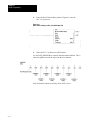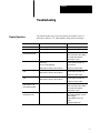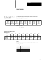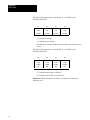
1
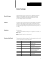
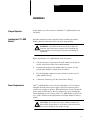
1771-QRD Pulse Flowmeter Module
Installation and User’s Manual
Important
This module is designed for use ONLY as an operating control. Where an
operating control failure would result in personal injury and/or loss of
property, it is the responsibility of the system designer or end user to add
devices (safety, limit controls) or other systems (alarm, supervisory
systems) that protect against or warn of control failure.
Solid state equipment has operational characteristics differing from those
of electromechanical equipment. ‘Application Considerations for Solid
State Controls’ (publication SGI–1.1) describes some important differences
between solid state equipment and hard wired electromechanical devices.
Because of this difference, and also because of the wide variety of uses for
solid state equipment, all persons responsible for applying this equipment
must satisfy themselves that each intended application is acceptable.
In no event will Allen-Bradley Company be responsible or liable for
indirect or consequential damages resulting from the use or application of
this equipment.
The examples and diagrams in this manual are included solely for
illustrative purposes. Because of the many variables and requirements
associated with any particular installation, Allen-Bradley Company cannot
assume responsibility or liability for actual use based on the examples and
diagrams.
No patent liability is assumed by Allen-Bradley Company with respect to
use of information, circuits, equipment or software described in this
manual.
Reproduction of the contents of this manual, in whole or part, without
written permission of the Allen-Bradley Company is prohibited.
copyright 1990 Allen-Bradley Company
1–1
Table of Contents
Before You Begin . . . . . . . . . . . . . . . . . . . . . . . . . . . . . . . .
1
Manual's Purpose . . . . . . . . . . . . . . . . . . . . . . . . . . . . . . . . . . .
Audience . . . . . . . . . . . . . . . . . . . . . . . . . . . . . . . . . . . . . . . . . .
Vocabulary . . . . . . . . . . . . . . . . . . . . . . . . . . . . . . . . . . . . . . . .
Overview of the Manual . . . . . . . . . . . . . . . . . . . . . . . . . . . . . . .
Warnings and Cautions . . . . . . . . . . . . . . . . . . . . . . . . . . . . . . .
Explosion Hazard . . . . . . . . . . . . . . . . . . . . . . . . . . . . . . . . . . . .
Related Products . . . . . . . . . . . . . . . . . . . . . . . . . . . . . . . . . . . .
Product Compatibility . . . . . . . . . . . . . . . . . . . . . . . . . . . . . . . . .
Related Publications . . . . . . . . . . . . . . . . . . . . . . . . . . . . . . . . . .
1
1
1
1
2
2
2
3
3
Introduction . . . . . . . . . . . . . . . . . . . . . . . . . . . . . . . . . . . .
1
Chapter Objectives . . . . . . . . . . . . . . . . . . . . . . . . . . . . . . . . . . .
Module Description and General Features . . . . . . . . . . . . . . . . . .
How the 1771-QRD Works . . . . . . . . . . . . . . . . . . . . . . . . . . . . .
How the 1771-QRD Communicates With Programmable Controllers
Chapter Summary . . . . . . . . . . . . . . . . . . . . . . . . . . . . . . . . . . .
1
1
2
3
3
Installation . . . . . . . . . . . . . . . . . . . . . . . . . . . . . . . . . . . . .
1
Chapter Objective . . . . . . . . . . . . . . . . . . . . . . . . . . . . . . . . . . .
Installing the 1771-QRD Module . . . . . . . . . . . . . . . . . . . . . . . . .
Power Requirements . . . . . . . . . . . . . . . . . . . . . . . . . . . . . . . . .
Module Location in the I/O Chassis . . . . . . . . . . . . . . . . . . . . . . .
Module Keying . . . . . . . . . . . . . . . . . . . . . . . . . . . . . . . . . . . . . .
...............................................
Wiring . . . . . . . . . . . . . . . . . . . . . . . . . . . . . . . . . . . . . . . . . . . .
Electrostatic Discharge . . . . . . . . . . . . . . . . . . . . . . . . . . . . . . . .
Module Installation . . . . . . . . . . . . . . . . . . . . . . . . . . . . . . . . . . .
Indicators . . . . . . . . . . . . . . . . . . . . . . . . . . . . . . . . . . . . . . . . .
Chapter Summary . . . . . . . . . . . . . . . . . . . . . . . . . . . . . . . . . . .
1
1
1
2
2
2
2
3
3
7
7
Module Programming . . . . . . . . . . . . . . . . . . . . . . . . . . . .
1
Chapter Objectives . . . . . . . . . . . . . . . . . . . . . . . . . . . . . . . . . . .
Reading Data From The Module . . . . . . . . . . . . . . . . . . . . . . . . .
Overrange and Overflow . . . . . . . . . . . . . . . . . . . . . . . . . . . . . . .
Block Transfer Programming . . . . . . . . . . . . . . . . . . . . . . . . . . . .
Example #1: PLC-5/15 Processor in a Local 1771 Backplane . . . .
Example #2: PLC-5/15 with Remote I/O . . . . . . . . . . . . . . . . . . . .
Example #3: PLC-3/10 with Remote I/O . . . . . . . . . . . . . . . . . . . .
1
1
2
2
3
8
12
ii
Table of Contents
More on Overrange and Overflow . . . . . . . . . . . . . . . . . . .
1
Chapter Objectives . . . . . . . . . . . . . . . . . . . . . . . . . . . . . . . . . . .
Frequency Overrange Flags . . . . . . . . . . . . . . . . . . . . . . . . . . . .
Totalizer Overflow Flags . . . . . . . . . . . . . . . . . . . . . . . . . . . . . . .
Using A Block Transfer Write to Reset the Totalizer(s)
and/or Overflow Flags . . . . . . . . . . . . . . . . . . . . . . . . . . . . . .
Chapter Summary . . . . . . . . . . . . . . . . . . . . . . . . . . . . . . . . . . .
1
1
2
Troubleshooting . . . . . . . . . . . . . . . . . . . . . . . . . . . . . . . .
1
Chapter Objectives . . . . . . . . . . . . . . . . . . . . . . . . . . . . . . . . . . .
1
Data Formats . . . . . . . . . . . . . . . . . . . . . . . . . . . . . . . . . . .
1
Block Transfer Write Format From PLC to QRD . . . . . . . . . . . . . .
Response from QRD to PLC Block Transfer . . . . . . . . . . . . . . . . .
1
1
Specifications . . . . . . . . . . . . . . . . . . . . . . . . . . . . . . . . . .
1
Power Requirements . . . . . . . . . . . . . . . . . . . . . . . . . . . . . . . . .
Environment . . . . . . . . . . . . . . . . . . . . . . . . . . . . . . . . . . . . . . .
Agency Approval . . . . . . . . . . . . . . . . . . . . . . . . . . . . . . . . . . . .
Packaging . . . . . . . . . . . . . . . . . . . . . . . . . . . . . . . . . . . . . . . . .
Weight . . . . . . . . . . . . . . . . . . . . . . . . . . . . . . . . . . . . . . . . . . .
Capacity . . . . . . . . . . . . . . . . . . . . . . . . . . . . . . . . . . . . . . . . . .
Performance . . . . . . . . . . . . . . . . . . . . . . . . . . . . . . . . . . . . . . .
Operational Limits . . . . . . . . . . . . . . . . . . . . . . . . . . . . . . . . . . .
1
1
1
1
1
1
1
2
3
5
Chapter 1
Before You Begin
Manual's Purpose
This manual shows you how to apply the 1771–QRD Pulse Flowmeter
Module to an Allen-Bradley PLC system. It describes methods for
installation, programming, and troubleshooting the module. It also
provides examples of how to use the module.
Audience
You must be able to program and operate an Allen-Bradley programmable
controller to make efficient use of this module. In particular, you must
know how to program Block Transfer instructions. If you do not, refer to
the appropriate programming and operations manual for the processor you
are using.
Vocabulary
We refer to the:
Pulse Flowmeter Module (Catalog No. 1771–QRD) as “the module”, or
“the QRD”.
Programmable Controller as “the processor”.
Overview of the Manual
This manual is divided into 6 chapters. The following table provides a brief
overview of the topics covered in each chapter.
Chapter
Title
Topics Covered
2
Introduction
Description of module including
programmable features
3
Installation
Module power requirements, keying chassis
location, field wiring
4
Programming
Reading data from the module
Sample programs for various processors
5
More on Overrange and Overflow
Error codes
Block transfer write rung for resetting
totalizers and/or overflow flags
6
Troubleshooting
Symptom/solution guide
Appendix A
Data Formats
Data formats fore Blcok Transfer Write and
Block Transfer Read
Appendix B
Specifications
1–1
Chapter 1
Before You Begin
Warnings and Cautions
Warnings are found in this manual and on the equipment. The following
symbols are used:
WARNING: A warning symbol means people might be injured
if the the procedures are not followed.
CAUTION: A caution symbol is used when machinery could
be damaged if the procedures are not followed. Explosion
Hazard
Explosion Hazard
WARNING: Explosion hazard — substitution of components
may impair suitability for Class 1. Division 2
AVERTISSEMENT: Risque d’explosion — la substitution de
composants peut rendre ce matériel inacceptable pour les
emplacements de Classe 1, Division 2.
WARNING: Explosion hazard — do not disconnect equipment
unless power has been switched off or the area is known to be
non-hazardous.
AVERTISSEMENT: Risque d’explosion — avant de
déconnecter l’équipement, couper le courant ou s’assurer que
l’emplacement est designe non dangereux.
Related Products
The 1771–QRD Module can be installed in any system that uses
Allen-Bradley PLC–2, PLC–3 or PLC–5 Programmable Controllers with
Block Transfer capability and 1771 I/O structure.
Contact your nearest Allen-Bradley office for more information about
programmable controllers.
1–2
Chapter 1
Before You Begin
Product Compatibility
Do not put the module Do not put the module in the same module group
as a discrete high-density module with 2 slot addressing.
Avoid placing the module adjacent to AC modules or high voltage DC
modules.
Related Publications
Consult the Allen-Bradley Industrial Computer Group Publications Index
(SD 499) for more information about programmable controllers.
1–3
Chapter 1
Before You Begin
1–4
Chapter 2
Introduction
Chapter Objectives
In this chapter you will read about:
1771–QRD Pulse Flowmeter Module features
How the 1771–QRD Module communicates with programmable
controllers
Module Description and
General Features
The Catalog No. 1771–QRD Pulse Flowmeter Module is an intelligent
block transfer module that interfaces Programmable Controllers with
magnetic pickups, single channel shaft encoders, and turbine flowmeters,
or with any source of TTL pulses. The module is generally compatible
with, but does not require the use of, turbine flowmeter signal
preconditioning modules. It provides rate and count data in 2’s
complement binary format to the processor data table through block data
transfers.
Rates as high as 10.0 kHz and counts as large as 32,767 are supported. At
overflow, the count continues from zero and an overflow flag is set. The
overflow flag can be reset by the ladder logic. In addition, the PLC can
reset any or all counts directly.
The module functions with reduced performance in PLC–2 systems due to
their three digit BCD operation. Rates as high as 0.999 kHz are permitted
as are total counts of any size, provided that the PLC ladder polls the
module at intervals faster than it can acquire 999 counts.
The 1771–QRD module receives +5 Vdc operating voltage through the I/O
chassis backplane. It draws a maximum of 0.50 A from this supply.
The module is implemented in a 1771 single-density module form factor.
2–1
Chapter 2
Introduction
How the 1771-QRD Works
Figure 2.1
A Typical Channel
The QRD is operated with block transfers. Block Transfer Reads report the
count values, rates, and both overrange and overflow flags to the PLC.
Block Transfer Writes are used by the PLC to reset the total count or to
reset the overflow flags.
2–2
Chapter 2
Introduction
How the 1771-QRD
Communicates With
Programmable Controllers
The following is a step-by-step example of the information flow to and
from a 1771–QRD Module (Figure 2.2):
1.
External devices (magnetic pickups, single channel encoders)
generate signals that are conducted to the 1771–QRD module.
2.
The 1771–QRD module converts the incoming signals into counts
and rates, then stores these values until the PLC requests a transfer of
data.
3.
When instructed by the ladder program, the processor performs a
Block Transfer Read of the values and stores them in the processor’s
data table.
4.
In the case of a count overflow, the ladder program can sense the
overflow and reset the overflow flag, if desired, using data from
within a Block Transfer Write command. Any or all of the totalizers
can also be reset. (Note that when the totalizers are reset the overflow
flags are also reset.)
5.
In the case of a rate overrange, the ladder program can sense the
overrange condition and act upon it accordingly.
6.
The ladder program can use and/or move the data before it is written
over by the transfer of new data in a subsequent block transfer.
Figure 2.2
Information flow through a programmable controller/1771-QRD System
Chapter Summary
In this chapter you read about the functional aspects of the 1771–QRD
Module and how it communicates with a Programmable Controller.
2–3
Chapter 3
Installation
Chapter Objective
In this chapter you will read how to install the 1771–QRD module in the
I/O chassis.
Installing the 1771-QRD
Module
Read this installation section completely before installing the module.
Double check all connections before you begin programming.
WARNING: Disconnect and lock out all power from the
controller and system power supplies before installing and
wiring modules to avoid injury to personnel and damage to
equipment.
Before installing the 1771–QRD Module in the I/O chassis:
Power Requirements
1.
Calculate the power requirements of all the modules in the chassis.
See the section below titled “Power Requirements”.
2.
Determine the location of the module in the I/O chassis. See the
section titled “Module Location in the I/O chassis”.
3.
Key the backplane connectors in the I/O chassis. See the sect ion
titled “Module Keying”.
4.
Connect the field wiring. See the section titled “Wiring”.
The1771–QRD Module receives its power through the 1771 I/O chassis
backplane from the chassis power supply. It does not require any other
external power supply to function. When planning the system, consider the
power usage of all modules in the I/O chassis to prevent overloading the
chassis backplane or power supply. Each 1771–QRD Module requires 0.50
A at +5VDC. Add this to the requirements of all other modules in the I/O
chassis.
CAUTION: Do not insert or remove modules from the I/O
chassis while system power is on. Failure to observe this rule
may result in damage to the module circuitry.
3–1
Chapter 3
Installation
Module Location in the I/O
Chassis
Place the module in any I/O module slot of the I/O chassis except for the
extreme left slot. This slot is reserved for the programmable controllers or
adapter modules. In addition:
1.
Do not put the module in the same module group as a discrete
high-density module with 2-slot addressing. However, other
single-slot modules may be placed in the same module group.
2.
Do not put the module adjacent to AC or high voltage DC I/O
modules, to minimize electrical noise and temperature effects. Noise
can be minimized by grouping input and output modules together
within an I/O chassis.
See the user’s manual of any other intelligent I/O modules involved for
possible grouping limitations.
Module Keying
Module Keying Plastic keying bands, shipped with each I/O chassis
provide an easy method for keying I/O slots to accept only one type of
module. The module is slotted in two places on the edge of the rear circuit
board. The position of the keying bands on the backplane connector must
correspond to these slots to allow insertion of the module. You can key any
connector in an I/O chassis to receive this module except for the leftmost
connector reserved for processor or adapter modules. Place the keying
band between the following numbers labeled on the backplane connector:
between pins 2 and 4
between pins 6 and 8
You may change the positions of the bands if subsequent system design
and rewiring makes insertion of a different type of module necessary. Use
needle-nose pliers to insert or remove a keying band.
Wiring
WARNING: To avoid injury to personnel and damage to
equipment, disconnect and lock out power from the processor
and system power supplies before wiring the m module.
Connections to/from I/O devices are made to the field wiring arm (catalog
no. 1771–WG shipped with the module. Attach the wiring arm to the pivot
bar at the bottom of the I/O chassis. It pivots upward and connects with the
module so you can install or remove the module without disconnecting the
wires.
3–2
Chapter 3
Installation
The sensor cable must be shielded. The shield must extend the length of
the cable, but be connected only at the 1771–QRD end. The recommended
sensor wiring cable type is Belden 8761 or similar. The functions of the
individual terminals of the field wiring arm are shown in Figure 3.1.
The wiring diagrams for both magnetic pickups and TTL are shown in
Figures 3.2 and 3.3, respectively.
Electrostatic Discharge
Electrostatic Discharge Electrostatic discharge can damage the integrated
circuits in this module, if you touch the backplane connector pins. Avoid
electrostatic damage by observing the following precautions:
Touch a grounded object to rid yourself of charge before handling the
module.
Do not touch the backplane connector or connector pins.
When not in use, keep module in its static-shield bag.
CAUTION: Electrostatic discharge can degrade performance
or damage the module. Handle as stated above.
Module Installation
Now that you have determined the power requirements, location, keying
and wiring for the 1771–QRD Module, you are ready to install it in the I/O
chassis.
1.
Turn off power to the chassis.
2.
Place the module in the plastic tracks on the top and bottom of the
slot to guide the module into position.
3.
Seat the module into the connector by applying firm, even pressure.
Do not force the module into its backplane connector.
4.
Snap the chassis latch over the top of the module to secure its
position.
5.
Connect the wiring arm to the module.
6.
Turn on power to the chassis. The green “ACTIVE” light should be
illuminated. If it is not lit, there is no power being applied to the
module. Turn the power off, re-insert the module and try again.
Connect one or more signal sources to the 1771–QRD. The signal source
can be a magnetic pickup/turbine flowmeter or TTL pulses.
3–3
Chapter 3
Installation
Figure 3.1
Field Wiring Arm
WARNING: Explosion hazard. Do not disconnect equipment
unless power has been switched off or the area is known to be
nonhazardous.
AVERTISSEMENT: Risque d’explosion. Avant de
déconnecter l’équipment, couper le courant ou s’assurer que
l’emplacement est designe non dangereux.
3–4
Chapter 3
Installation
Figure 3.2
Wiring for Pickups or Flowmeters
3–5
Chapter 3
Installation
Figure 3.3
Wiring for Active TTL Drivers
Note: The jumper between terminals 17 and 19 changes the sensitivity of
channels 3 and 4 so that they are compatible with TTL pulses.
The jumper between terminals 17 and 20 changes the sensitivity of
channels 1 and 2 so that they are compatible with TTL pulses.
Signal types may not be mixed within a channel pair.
For use with magnetic pickups or turbine flowmeters, do not connect a
jumper to these terminals.
WARNING: Remove power from the 1771 I/O chassis
backplane and from the wiring arm before removing or
installing the module.
Failure to remove power from the backplane or the wiring arm could
cause module damage, degradation of performance or injury.
Failure to remove power from the backplane could cause injury or
equipment damage due to possible unexpected operation.
3–6
Chapter 3
Installation
Indicators
There are three indicator LEDs on the front panel. The indicator LED
functions are listed in Table 3.A.
Table 3.A
Indicators
Chapter Summary
Legend
Color
Type
Function
FAULT
Red
Solid
One or more inputs are above 10.0 kHZ
FAULT
Red
Flashing
Internal hardware failure, or input rates drifiting above
and below 10.0 kHz
PROG
Yellow
Flashing
Block transfer in process
ACTIVE
Green
Solid
Module active
In this chapter you read how to install the 1771–QRD Module in a
Programmable Controller system, as well as how to wire the field wiring
arm.
3–7
Chapter 4
Module Programming
Chapter Objectives
In this chapter you will learn about:
Reading data from the 1771–QRD module
Writing data to the 1771–QRD module
Black transfer programming format
Programming techniques
Reading Data From The
Module
Block Transfer Read programming moves 9 words from the 1771–QRD
Module to the processor’s data table. The ladder program initiates the
request to transfer data from the QRD to the processor.
Figure 4.1 illustrates the module’s response after the PLC processor’s
block transfer request for counts and rates.
Figure 4.1
Module's Response to Block Transfer Read Request
Word 0
1
0
0
Word 1
Channel 1 Rate
Word 2
Channel 1 Total
Word 3
Channel 2 Rate
Word 4
Channel 2 Total
Word 5
Channel 3 Rate
Word 6
Channel 3 Total
Word 7
Channel 4 Rate
Word 8
Channel 4 Total
0
4–1
Chapter 4
Module Programming
Word 0 (1000) is the header code that identifies the data source as a
1771–QRD module. When the module is active, it also contains the status
of the overrange and overflow flags. Overrange and overflow are discussed
in more detail in the next section of this chapter. Word #1 contains the rate
of the signal on channel 1; word #2 contains the total number of pulses
received on channel 1. Word #3 contains the rate of the signal on channel
2; word #4 contains the total number of pulses received on channel 2.
Word #5 contains the rate of the signal on channel 3; word #6 contains the
total number of pulses received on channel 3. And finally, words #7 and #8
contain the rate and total number of pulses received on channel 4,
respectively.
Overrange and Overflow
The 1771–QRD processes input signals at a maximum rate of 10.0kHz. If
the rate of the incoming signal on any channel is greater than 10.0 kHz, the
red FAULT indicator will illuminate, revealing an overrange. At the same
time, a bit will be set in the acknowledge word (word 0), showing the
channel(s) whose rate is in an overrange condition. The red FAULT light
will extinguish only when the frequency of the input that is causing the
overrange is reduced to less than 10.0 kHz. At that time, the FAULT light
will go out, and the overrange flag for that channel will automatically be
reset. Overrange rates are reported as zero values, and cause their totalizers
to reset to zero.
The 1771–QRD also acts as a totalizer for each of the channels. Each of
the totalizers is capable of counting up to 32,767. When this number is
reached by any of the totalizers, an overflow flag for that channel is set in
the acknowledge word. The counter will again start from zero and continue
to count, with the overflow flag set. These flags can be detected by the
processor, and any or all of them can be reset using a Block Transfer Write
command. Examples of the detection and handling of overflow conditions
with a BTW command are discussed further in Chapter 5.
Block Transfer Programming
4–2
The following sections show how to program and set up typical
programmable controllers for use with the 1771–QRD Module. In each
example, the switch settings for all of the processors and adapters used are
given, as well as the backplane settings for the I/O chassis. Note that 2-slot
addressing is used in all of these examples, but the 1771–QRD will
function with any type of addressing (2-slot, 1-slot, 1/2-slot).
Chapter 4
Module Programming
The following table outlines the examples that are contained in this
chapter:
Table 4.A
Examples Contained in This Section
Example Number
System Type
Page
1
PLC-5/15 in a local 1771 backplane
4-3
2
PLC-5/15 with Remote I/O
4-8
3
PLC-3/10 with Remote I/O
4-12
These examples represent the most common configurations for a controller
system. One of them should be close enough to your application to be used
as a guide.
Example #1: PLC-5/15
Processor in a Local 1771
Backplane
1.
Install the 1771–QRD module in a 1771 backplane. Figure 4.2
illustrates a PLC–5/15 configured for 2-slot addressing.
Figure 4.2
2Slot Addressing Configuration Example
4–3
Chapter 4
Module Programming
The eight physical slots labeled with Rack/Group/Slot (RGS) addresses in
Figure 4.2 would have different RGS addresses if single or 1/2 slot
addressing were chosen.
Please refer to Figure 4.3 for dual, single, or 1/2 slot addressing RGS
numbers.
WARNING: Remove system power and power to all devices
connected to the swing arm terminals before removing or
installing your module into the 1771 I/O chassis. Failure to
observe this warning could result in damage to the module
circuitry and/or undesired operation with possible injury to
personnel.
Figure 4.3
Dual, Single and Half Slot Addressing for Rack 0
DualSlot
4–4
SingleSlot
HalfSlot
Slot
Number
RGS
Slot
Number
RGS
Slot
Number
RGS
1
000
1
000
1
000
2
001
2
010
2
020
3
010
3
020
3
040
4
011
4
030
4
060
5
020
5
040
5
100
6
021
6
050
6
120
7
030
7
060
7
140
8
031
8
070
8
160
Chapter 4
Module Programming
2.
Set the PLC–5/15 configuration switches as shown in Figure 4.4.
Figure 4.4
PLC-5/15 Configuration Dip Switches
NOTE: The black area indicates the selected switch position (up or down).
3.
Set the 1771 backplane dip switch as shown in Figure 4.5.
Figure 4.5
1771 Backplane Dip Switch.
NOTE: The black area indicates where the switch should be pressed with
a pencil or other sharp instrument.
The backplane is now set up for 2 (dual) slot addressing.
4–5
Chapter 4
Module Programming
4.
Apply power to the I/O chassis. Enter the Block Transfer rung shown
in Figure 4.6 into the PLC–5/15 processor.
Figure 4.6
Block Transfer Rung for a PLC-5/15 Processor
NOTE: If the module is installed in a physical slot other than the fifth slot
to the right of the PLC processor, the BTR block will have to be set up
with a Rack/Group/Slot address other than 020. Refer to Figure 4.3 for the
correct address settings.
5.
Place the PLC–5/15 processor into RUN mode.
Use the Data Monitor in the 6200 Series Software to examine data table
address N36:0. This is where the processor has stored the rates and total
counts received from the 1771–QRD.
Only the channels which are actually driven will be active.
4–6
Chapter 4
Module Programming
If all four input channels are being driven, we see that the value that
appears at address #1 is the rate of the signal that appears at swingarm
terminals 3 and 4. Note that the value that appears at address #3 is the rate
of the signal that appears at swingarm terminals 6 and 7; the value
appearing at address #5 is the rate of the signal that appears at swingarm
terminals 9 and 10; and finally, the value that appears at address #7 is the
rate of the signal that appears at swingarm terminals 12 and 13. The totals
for each of the channels appear to the right of their respective rates; i.e.
channel 1 rate (word #1) is accompanied by channel 1 total (word #2);
Channel 2 rate (word #3) is accompanied by channel 2 total (word #4);
Channel 3 rate (word #5) is accompanied by channel 3 total (word #6); and
channel 4 rate (word #7) is accompanied by channel 4 total (word #8). The
acknowledgement code of 1000 (in word 0) identifies the module as
1771–QRD Pulse Flowmeter Module.
4–7
Chapter 4
Module Programming
Example #2: PLC-5/15 with
Remote I/O
1.
Install the module in the remote 1771 backplane,as shown in Figure
4.7.
Figure 4.7
PLC-5/15 in a Local Backplane With an ASB in a Remote Backplane
4–8
Chapter 4
Module Programming
2.
Set the PLC–5/15 configuration dip switches, as shown in Figure 4.8.
Figure 4.8
PLC-5/15 Configuration Dip Switches
NOTE: The black area indicates the selected switch position (up or down).
3.
Set the 1771 Backplane dip switch, as shown in Figure 4.9.
Figure 4.9
Backplane Dip Switches
NOTE: The black area indicates where the switch should be pressed with
a pencil or other sharp instrument.
The local chassis is now configured for 2-slot addressing.
4–9
Chapter 4
Module Programming
4.
Set the 1771–ASB configuration switches, as shown Figure 4.10.
Figure 4.10
1771-ASB Configuration Dip Switches
NOTE: The black area indicates where the switch should be pressed with
a pencil or other sharp instrument.
5.
Set the remote 1771 backplane dip switch, as shown in Figure 4.11.
Figure 4.11
1771 Remote Backplane Dip Switch
NOTE: The black area indicates where the switch should be pressed with
a pencil or other sharp instrument.
The remote chassis is now configured for 2-slot addressing.
4–10
Chapter 4
Module Programming
6.
Enter the Block Transfer Rung found in Figure 4.12 into the
PLC–5/15.
Figure 4.12
Block Transfer Rung for a PLC-5/15 With Remote I/O
7.
Place the PLC–5/15 Processor in RUN mode.
Use the DATA MONITOR to examine data table address N36:0. This is
where the QRD has stored the data from the four channels. They will
appear as:
Only the channels which are actually driven will be active.
4–11
Chapter 4
Module Programming
Example #3: PLC-3/10 with
Remote I/O
1.
Install the module in the remote 1771 backplane, as shown in Figure
4.13.
Figure 4.13
PLC-3/10 with an ASB in a Remote Backplane
4–12
Chapter 4
Module Programming
2.
Set the 1771–ASB configuration switches, as shown in Figure 4.14.
Figure 4.14
1771-ASB Configuration Dip Switches
NOTE: The black area indicates where the switch should be pressed with
a pencil or other sharp instrument.
3.
Set the 1771 Remote Backplane dip switch, as shown in Figure 4.15.
Figure 4.15
1771 Remote Backplane Dip Switch
NOTE: The black area indicates where the switch should be pressed with
a pencil or other sharp instrument.
The remote chassis is now configured for 2-slot addressing.
4–13
Chapter 4
Module Programming
4.
Enter the Block Transfer Rung found in Figure 4.16 into the
PLC–3/10 processor.
Figure 4.16
Block Transfer Rung for a PLC-3/10 with Remote I/O
5.
Place the PLC–3/10 Processor in RUN mode.
Use the DATA MONITOR to examine data table address #N40:0. This is
where the QRD has stored the rates from the four channels.
Only the channels which are actually driven will be active.
4–14
Chapter 5
More on Overrange and Overflow
Chapter Objectives
In this chapter you will learn more about the overrange and overflow status
flags sent from the QRD to the PLC. You will also learn how to use a
Block Transfer Write to clear the overflow bits, the totalizers or any
combination of both.
Frequency Overrange Flags
As discussed in Chapter 4, an overflow occurs when the value of any of the
four totalizers exceeds the maximum value of 32,767. At that time, an
overflow flag for that channel is set and can be seen in the first word of the
Block Transfer data table. These overflow flags can be reset by the ladder
logic. Any or all of the totalizers can also be reset either independently of
each other, or they can all be reset simultaneously.
When it detects an overflow, the 1771–Q RD sets an overflow flag in the
acknowledge word (word 000) of the Block Transfer Read response. The
best way to understand this concept is to break down the acknowledge
word into bit format. The 16 bits are grouped by function into four
categories (Figure 5.1):
Figure 5.1
Acknowledge Word (From 1771-QRD Module)
Table 5.A
Error Codes from Acknowledge Word
Code
Meaning
0
Valid Data
1
Channel Pair Fault
2
BLOCK TRANSFER Syntax Error
4
Channel Pair Fault and Syntax Error
5–1
Chapter 5
More on Overrange and Overflow
Each time an input for one (or more) of the channels is greater than 10.0
kHz, the overrange flag for that channel is set; for example, if the input
frequency for channel 1 is greater than 10.0 kHz, bit #4 is set. (This is the
first bit of the overrange group.)
Acknowledge Word = 1010 = 0001
XXXX
XXX1
0000
Overrange, Channel 1
If the input frequency for any other channel is greater than 10.0 kHz, the
QRD sets the appropriate bit in the acknowledge code. It is possible for all
channels to be in an overrange condition; in such a case, the acknowledge
code would be:
Acknowledge Word = 10F0 = 0001
XXXX
1111
00000
All inputs are overrange (u10.0 kHz)
Totalizer Overflow Flags
The overflow flags work in the same manner as the overrange flags. As an
example, when totalizer #1 has reached its maximum (32,767), an
overflow flag (bit #8) is set in the acknowledge code. If the acknowledge
code is put in binary format, it looks like this:
Acknowledge Code = 1100 = 0001
XXX1
XXXX
0000
Overflow, Channel 1
Any or all of the four channels can overflow, and any or all of the overflow
flags can be reset using a Block Transfer Write command. If all of the
channels overflow, the acknowledge code will look like:
Acknowledge Code = 1F00 = 0001
1111
XXXX
0000
All inputs are overflowed (u32,767)
5–2
Chapter 5
More on Overrange and Overflow
Using A Block Transfer Write
to Reset the Totalizer(s)
and/or Overflow Flags
Any or all of the totalizers and overflow flags can be reset using a Block
Transfer Write command sent to the 1771–QRD from the PLC. For a
PLC–5 processor, the rung might look like this:
The Block Transfer Write sends the 1771–QRD one word that contains the
correct bit pattern to reset the totalizer(s) and/or overflow flags. The BTW
data word can be changed through the ladder logic, or by editing the data
table.
Note that the Block Transfer Write is switch selectable, and its length is
one word. The block transfer should only be sent once unless the ladder
intelligently sets and clears the reset bits within the Block Transfer data. As
an example, the ladder might set the reset bit at the time of overflow. If the
Block Transfer is sent continuously and the reset bits contained within the
Block Transfer data are simply left set to “1”, the transfers will constantly
be resetting the totalizer(s) and/or overflow flags of the specified channels.
The word from the block transfer data table would appear in the DATA
MONITOR as:
N41:0
00XX
Where: “XX” are the 8 bits used to reset the totalizer(s) and/or overflow bits.
Breaking down the word in the data table into binary format:
N41:0
0000
0000
XXXX
4321
XXXX
4321
To reset overflow flags
To reset totalizers
The numbers underneath the “X” ’s are the channel numbers that are
affected when the corresponding bit is a “1”. Note that a “1” resets the
totalizer(s) and/or overflow bits, and a “0” leaves them unchanged.
NOTE: Resetting the totalizer(s) will automatically reset its respective
overflow flag(s).
5–3
Chapter 5
More on Overrange and Overflow
Figure 5.2
Example of Detecting and Resetting an Overflow Flag on Channel 1
5–4
Chapter 5
More on Overrange and Overflow
The example in Figure 5.2 detects a count overflow on Channel 1, and
resets the overflow bit for that channel with a Block Transfer Write
command. The ladder logic also keeps track of the total number of counts
received at the channel 1 inputs.
A similar ladder could reset the overflow bits for channels 2, 3, and 4 by
setting bits 165, 166, and 167 of data table B3. The actual totals for the
four channels could be reset by setting bits 160, 161, 162, and 163 of data
table B3.
Although not shown in the previous examples, it is good PLC–5
programming procedure to include a rung to reset the EN bit of a block
transfer control file when the ER bit is set, when continuous transfers are
used.
Chapter Summary
In this chapter, you learned the structure of the acknowledge code sent
from the QRD and how to reset the totalizer(s) and/or the overflow flags.
You also learned about the overrange condition, and how to detect it.
Finally, you learned the structure of the Block Transfer Write command
that is sent to the QRD Module for resetting overflow flags and/or
totalizer(s).
5–5
Chapter 6
Troubleshooting
Chapter Objectives
The following table may be used to identify the probable cause of
difficulties with the 1771–QRD Module during initial installation.
Symptom
Probable Causes
Possible Solutions
No indicators lit
Power not applied
Check that power supply is turned on
Green light off
Power not applied
Firmly reseat module in backplane
Red, green indicators solid,
yellow indicator flashing
Rate overrange
Decrease input frequencies
Check connection of cable shield(s)
Move signal cable away from
electrical noise sources
Yellow light off
No block transfer writes
done
No block transfer reads
done
Wrong rack, group, slot address used in block
transfer rung
Verify correct address in ladder rung
for block transfer (See table 4.3)
Processor in Program Mode
Set to run mode
Wrong address setting on chassis switches
Verify chassis switch settings
Wrong rack, group, slot address
Verify correct address in ladder rung
for block transfer (See table 4.3)
Wrong address setting on chassis switches
Wrong rack, group, slot address
Verify chassis switch settings
Wrong address setting on chassis switches
Verify correct address in ladder rung
for block transfer (See table 4.3)
All zeros in data table, red,
green indicators solid,
yellow indicator flashing
Frequency overrange
Decrease input frequencies
Data table values not being
incremented; no rate
Wrong signal type or low signal voltage
Verify chassis switch settings
Check connection of cable shield(s)
Move signal cable away from
electrical noise sources
Verify jumpers between terminals 17
and 19, and/or terminals 17 and 20
on the swingarm.
Jumper is ONLY used for TTL
signals.
Verify input voltage levels
6–1
Chapter 6
Troubleshooting
6–2
Symptom
Probable Causes
Possible Solutions
Data counts to small value,
then jumps to zero
Continuous BTW Reset
Check ladder program to be sure that
the block transfer write is not causing
continuous resets of the totalizer(s)
Rates and counts from one
input appear in more than
one channel position in the
data table
Wiring reversal of + and - inputs
Refer to wiring diagrams
Appendix A
Data Formats
Block Transfer Write Format
From PLC to QRD
Use this block format to reset totalizer(s) and/or overflow flag(s).
Note: b8 through b15 are unused.
b7
b6
b5
b4
b3
b2
b1
b0
RESET
RESET
RESET
RESET
RESET
RESET
RESET
RESET
CH 4
CH 3
CH 2
CH 1
CH4
CH3
CH2
CH1
Overflow Flag
Overflow Flag
Overflow Flag
Overflow Flag
TOTAL
TOTAL
TOTAL
TOTAL
Where: “1”=reset
“0” = not reset
Response from QRD to PLC
Block Transfer
first
second
third
fourth
fifth
sixth
seventh
eighth
ninth
word
word
word
word
word
word
word
word
word
RESPONSE CODE
CH 1
CH 1
CH 2
CH 3
CH 3
CH 4
CH 4
CH 4
AND ERROR
RATE
TOTAL
RATE
TOTAL
RATE
TOTAL
RATE
TOTAL
CODE (1XYZ)
Notes:
The digit in the response/error code labeled “Z” will adhere to the
following definitions:
Code
Meaning
0
Valid data
1
Channel pair default
2
BLOCK TRANSFER syntax error
3
Channel pair fault and syntax error
A–1
Appendix A
Data Formats
The digit in the response/error code labeled “Y” will adhere to the
following definitions:
b7
b6
b5
b4
channel
channel
channel
channel
4 rate
3 rate
2 rate
1 rate
overrange
overrange
overrange
overrange
“1” indicates overrange
“0” indicates not overrange
Note that the overrange condition causes both the rate and total to be
zeroed
The digit in the response/error code labeled “X” will adhere to the
following definitions:
b11
b10
b9
b8
channel
channel
channel
channel
4 total
3 total
2 total
1 total
overflow
overflow
overflow
overflow
flag
flag
flag
flag
“1” indicates totalizer has overflowed
“0” indicates totalizer has not overflowed
Important: When the totalizer overflows, it continues to count unless
manually reset.
A–2
Appendix B
Specifications
Power Requirements
DC Supply Voltage from Backplane: 5 Volts " 5% @ 0.50 A Maximum
Note: This supply must meet the Allen–Bradley series B power bus
specification. Typical supplies are 1771–P3, –P4, –P5, and –P7.
Isolated Field Supply Required: none
Environment
Operating Temperature: 0 degrees C to 60 degrees C
Storage Temperature: minus 40 degrees C to 85 degrees C
Operating Humidity: 5% – 95 % relative (non–condensing)
Agency Approval
UL (Pending), CSA Class I, Division 2, Group D
Packaging
Single slot 1771 I/O module, 21 terminals, swing arm connector
Weight
1.0 lb (approximately)
Capacity
Hardware channels per module: 4
Independent ratemeters per module: 4
Independent totalizers per module: 4
Performance
Ratemeter update time: 1.0 Second
Block transfer time: Less than 10 mS
Note: Ladders longer than 10 mS or STI files with repeat intervals longer
than 10 mS will receive updated totals once per scan or STI.
B–1
Appendix B
Specifications
Operational Limits
Signal Characteristics, Turbine Flowmeter or Magnetic Pickup: 50 mV
to 142 VAC RMS
The signal should be approximately sinusoidal and must be AC. The signal
must be greater than 50 mV peak to peak, and must be smaller than 400 V
peak to peak.
Signal Characteristics, TTL: 1.3 V threshold
The signal should be DC pulses with width greater than 20 uS. The logic
“1” level must be greater than + 1.3 V and smaller than +200 V while the
logic “0” level must be larger than –.7V and smaller than +1.3V.
The TTL mode is compatible with TTL, 4,000 series CMOS, and most
0–24 V systems. The TTL mode is not compatible with any signal format
with DC pulses riding on a fixed DC level greater than + 1.3 V.
Note: Signal type is selectable by swing arm jumper. Channel thresholds
are jumpered in pairs.
Input Impedance: 5 kOhm " 30% resistive, minimum
Isolation: 1000 V minimum between channels and microcontroller, and
between channel pairs
Accuracy: 0.1% "1 Hz for frequency t 3.0 kHz 0.2% "1 Hz for
frequency u 3.0 kHz
Overrange Indication: Individual bit for each channel set to indicate rate
above 10 kHz
Overflow Indication: Individual bit for each channel set to indicate total
above 32, 767
Overrange Response: When a channel signal exceeds 10 kHz the rate
overrange bit will be set, the total reset to zero, and the rate for that
channel reported as zero
Maximum Operating Frequency: 10.0 kHz for PLC–3 and PLC–5, 0.999
kHz for PLC–2 (New Use)
Total Control: Overflow bit and total can be cleared by ladder logic.
Clearing total also clears overflow bit
B–2
Appendix B
Specifications
With offices in major cities worldwide
WORLD
HEADQUARTERS
Allen-Bradley
1201 South Second Street
Milwaukee, WI 53204 USA
Tel: (1) 414 382-2000
Telex: 43 11 016
FAX: (1) 414 382-4444
EUROPE/MIDDLE
EAST/AFRICA
HEADQUARTERS
Allen-Bradley Europe B.V.
Amsterdamseweg 15
1422 AC Uithoorn
The Netherlands
Tel: (31) 2975/43500
Telex: (844) 18042
FAX: (31) 2975/60222
As a subsidiary of Rockwell International, one of the world’s largest technology
companies — Allen-Bradley meets today’s challenges of industrial automation with over
85 years of practical plant-floor experience. More than 11,000 employees throughout the
world design, manufacture and apply a wide range of control and automation products
and supporting services to help our customers continuously improve quality, productivity
and time to market. These products and services not only control individual machines but
integrate the manufacturing process, while providing access to vital plant floor data that
can be used to support decision-making throughout the enterprise.
ASIA/PACIFIC
HEADQUARTERS
Allen-Bradley (Hong Kong)
Limited
Room 1006, Block B, Sea
View Estate
28 Watson Road
Hong Kong
Tel: (852) 887-4788
Telex: (780) 64347
FAX: (852) 510-9436
CANADA
HEADQUARTERS
Allen-Bradley Canada
Limited
135 Dundas Street
Cambridge, Ontario N1R
5X1
Canada
Tel: (1) 519 623-1810
FAX: (1) 519 623-8930
LATIN AMERICA
HEADQUARTERS
Allen-Bradley
1201 South Second Street
Milwaukee, WI 53204 USA
Tel: (1) 414 382-2000
Telex: 43 11 016
FAX: (1) 414 382-2400
Publication 1771–6.5.73 — November 1990
Printed in USA
B–4