1
Product Data
Encoder/Counter Module
AllenBradley
Encoder/Counter Module
(Cat. No. 1771-IJ, -IK)
Product Data
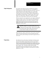
Description
The Encoder/Counter Module Assembly (cat. no. 1771-IJ or 1771-IK)
maintains a count, independent of the processor, of input pulses that may
typically originate from such devices as quadrature type encoders, high
speed optical beam counters, and certain types of switches. The module is
capable of making decisions based on the count total by comparing it to
previously programmed preset values and activating either one or both of
its outputs based on the results of the comparison. The module can also
return the accumulated count to the processor for arithmetic computations
or display. The module is compatible with any Allen-Bradley
programmable controller employing the 1771I/O structure.
The module also provides inputs for a marker signal from an encoder and a
voltage level signal from a limit switch to allow for home positioning. In
the count mode, you can change the direction of the count either from the
processor or at the module itself through an external switch. The maximum
detectable input pulse frequency to the module is 50kHz.
1
Product Data
Encoder/Counter Module
The module counts in either BCD or binary numbers. In the BCD mode,
the range is 000 to 999. The binary mode allows a higher count total, with
a range of 0000 to 4095. Carry and borrow bits are provided to cascade
counters in the program.
Additionally, the module can improve the accuracy of certain types of
encoders by counting the rising and falling edges of channel A (times 2
mode), or by counting the rising and falling edges of both channel inputs to
give a fourfold increase in the count (times 4 mode).
The encoder/counter module assembly is available in two versions:
Cat. No. 1771-IJ uses a 5V DC external power supply that allows inputs
to be TTL compatible. Outputs can either be driven from the 5V DC
supply through the module or from a separate load supply of a different
voltage.
Cat. No. 1771-IK uses a 12-24V DC external power supply. Input
devices should be compatible with the voltage of the customer power
supply. Outputs can be driven either from the customer supply through
the module or from a separate load supply.
The encoder/counter module assembly includes:
One Encoder/Counter Module (either cat. no. 1771-IJ or 1771-IK).
Two 12 terminal gold-plated Field Wiring Arms (cat. no.1771-WB).
Unless otherwise noted the following paragraphs refer to both versions of
the module.
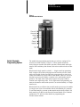
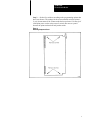
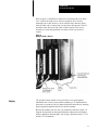
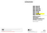
Status Indicators
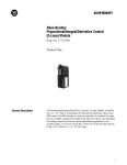
There are seven status indicators on the front of the left half of the module
(figure 1). The top four LEDs, corresponding to channal A, channel B,
marker, and limit switch inputs, illuminate when their respective input
signal is high. The next two indicators show the state of the outputs. An
output indicator is on when the output circuit is activated. The bottom
indicator illuminates when the module has detected a fault.
When system power is turned on, the module runs a self-test on its
components. During power-up, it is normal for the fault indicator to flash
on momentarily. If the LED does not turn off, the module has detected a
fault. The self-test includes checks to make sure that all counters and
registers have been reset to zero and memory is cleared. If a breakdown of
communication occurs during block transfer, the fault LED will also light.
(Bit 14, the diagnostic bit in the input status word, is also set anytime the
fault LED is on.)
After power-up, the module stays in its reset state (outputs disabled and
counter held reset) until the necessary control bits are set in the program.
2
Product Data
Encoder/Counter Module
Figure 1
Red LED Status Indicators
Switch Selectable
Programming Options
The module has programming options that you select by setting the five
switches on switch assembly 1 (figure 5). These options include the
choices between encoder and counter operation, block transfer and single
transfer, BCD and binary data formats, and count resolution in the encoder
mode.
Block transfer/single transfer (switch 1) — Single transfer programming
shifts a single word of data each program scan from the processor’s data
table to the module. It therefore takes three program scans to send a new
control word and the two preset values to the module. However, once new
data has been sent to the module, it remains active until another transfer
updates it. The input status word always appears at its proper address
location in the input image table. To use single transfer programming, you
must set the transfer mode switch (switch 1) on switch assembly 1 to single
transfer (on).
Block transfer moves all three data words from the processor to the module
in a single scan. (Note: Not avaliable with all Allen-Bradley PC products.)
To use block transfer, you must set the transfer mode switch (switch 1) for
block transfer (off). Refer to the Encoder/Counter Module User’s Manual
(publication 1771-807) for futher details on programming the
encoder/counter module.
3
Product Data
Encoder/Counter Module
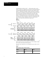
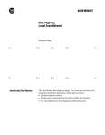
Count Resolution (switches 2 and 3) — In the encoder mode, you can
improve resolution of a quadrature type encoder by allowing the module to
count the leading and trailing edge of the pulse train at channel A input
(figure 2). This doubles the number of pulses counted for one rotation of
the encoder. You can improve the count resolution even further by letting
the module count the leading and trailing edges of both pulse trains,
thereby counting four times (times 4) for the same degree of rotation
(figure 2). Certain applications may need the actual count, in these cases,
set the module for times 1 (the pulse is counted on its rising edge as high
true). The count resolution setting affects the total count kept at the
module. This count is also sent back in the status word.
Figure 2
Input Pulses
In the counter mode, the count resolution (X1, X2, X4 multiplier) setting
has no affect on the count and can be ignored.
To set the count resolution for use with quadrature type encoders, refer to
Table A.
Table A
Count Resolution Setting on Switch Assembly 2
4
Multiplier
Switch 2
Switch 3
Times 1
Times 2
Times 4
ON
ON
OFF
ON
OFF
OFF
Product Data
Encoder/Counter Module
Encoder/Counter Selection (switch 4)- In the encoder mode, the module
counts the number of input pulses entering on channel A from a quadrature
type encoder. By comparing the phase relationship between input pulses on
channel A with the pulses appearing at channel B, it determines whether to
add or subtract the incoming count from the total, that is, whether to count
up or down (figure 2). The direction in which the encoder is turned
determines the phasing between the channels. To use the module in the
encoder mode, switch 4 must be set to encoder (on).
In the counter mode, the module totals the incoming pulses on channel A
only. The count increments on the rising edge of the pulse (high true). The
direction of the count is controlled with either the control word or an
external switch wired to channel B. If the count direction is software
controlled, do not connect channel B. Typical input devices for counting
might be high speed static switches and incremental encoders. Mechanical
switches are not recommended as input counting devices interfaced to the
1771-IJ module because contact bounce might be counted as pulses.
However, the 1771-IK module can be used with a mechanical switch,
provided the module is configured for mechanical counting (switch
assembly 2, switch 3 set for filtering) and the counting frequency does not
exceed 50Hz. To use the module in the counter mode, set switch 4 of
switch assembly 1, to counter (off).
Binary/BCD Data Format (switch 5)- You can select whether the preset
values and the accumulated total in the status word appear in either BCD
or binary formats. If you select the BCD format, the processor can directly
use these values in comparisons or arithmetic functions. The accumulated
count is limited to a value between 000 and 999. The binary option allows
an increased range of 0000 to 4095.
Input Configuration
Because different types of input devices are compatible with different
voltage ranges, the 1771-IJ (5V DC) and 1771-IK (1224V DC) module
input channels are configured differently.
1771IJ Module
Because the 1771-IJ module is designed to work with 5V TTL type
devices, you can set each input channel and the marker input for single
ended or differential line inputs (figure 5). The input device should be
capable of providing 16mA of sink current. The module detects a voltage
of 2.4V DC or above at either channel as logic “1” or true. A voltage
below 0.6V DC is considered a logic “0” or false.
5
Product Data
Encoder/Counter Module
The 1771-IJ module is compatible with encoders having any of these three
types of output circuits:
Totem-pole (TTL) — select single ended mode
Open-collector — select single ended mode
Differential — select differential mode
CAUTION: The 1771-IJ encoder module inputs are designed
to be driven by current-sinking drivers only. Do not use
current-sourcing type drivers as the channel A, channel B, and
marker inputs may be damaged if current is sourced into them.
The marker input registers as true when the marker pulse from the encoder
is high.
The limit switch input senses a voltage of greater than 10V DC as a logic
“1,” or on and less than 5V DC as a logic “0,” or off. The input voltage
that appears through the switch should be from a 12 to 48V DC customer
supply that is capable of supplying 10mA of source current at 48V DC.
Unlike the three encoder inputs, the limit switch is designed to have
current sourced into it. The limit switch input has a signal delay of 16ms
("7ms) because of the filtering needed to protect against contact bounce.
Use the channel B input in the counter mode to select count direction. If
the channel B input terminal is not connected, the control word in the
output program selects the direction of the count. For external hardware
control, you must set the count direction bit in the control word to count
up. Then if channel B is allowed to float high or is driven high, the module
counts up; if the signal at channel B is pulled low, either through a gate or
a transistor switch, the module will count down.
Use a transistor switch or gate to pull the channel B input low. Mechanical
switches may produce contact bounce which the module would interpret as
a change of state and increment or decrement its count. The gate or switch
must sink 16mA to pull the channel B input low.
It is important to recognize that the channel A, B, and marker inputs are
designed to be driven by solid state devices which will sink current out of
the module’s terminals in the “low” state. The limit switch input is
designed to have current sourced into it.
6
Product Data
Encoder/Counter Module
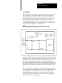
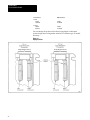
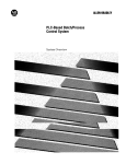
1771IK Module
The 1771-IK module is designed to accept devices that operate in the 12 to
24V range (figure 3). Since most quadrature encoder outputs produce
signals through an open collector output, the module is configured for a
pull-up on channel B. Set channel A for a pull-up by setting switch 1 on
switch assembly 2. Some counting devices may also use a pull-up
arrangement. When switch 1 is on, switch 2 should be off. Note that the
settings on switch assembly 2 are not the same on the 1771-IJ as they are
for 1771-IK. Refer to figure 5 for switch settings.
Figure 3
Switch Assembly 2Input Configuration for Channel A of the 1771IK
Certain counting devices may need an input designed to pull current down
through the device. Set switch 2 on for pull-down and set switch 1 off. The
module detects a minimum of 8.0V DC at its input channels as true for a
12V DC customer supply and 16.0V DC at 24V DC customer supply. A
signal with a maximum voltage of 4.0V DC is considered false for a 12V
DC supply; 8.0V DC is false for a 24V DC supply. The device driving each
input must be able to sink 10mA into itself at 12V DC and 20mA at 24V
DC.
The 1771-IK module is designed to be compatible with encoders having
current sinking, open collector output drivers. Use of encoders with current
sourcing outputs is not recommended since the marker input may be
damaged if current is sourced into it. As noted above, the user has the
option to configure the channel A input for a current-sourcing input (e.g.
limit switch connected to a DC supply).
7
Product Data
Encoder/Counter Module
If it is necessary to debounce a contact type of device, such as a switch,
you can add the filter across the inputs by setting switch 3 on of switch
assembly 2. Notice that with the filter switched in a minimum signal equal
to the customer supply voltage, the module can detect signals up to 50Hz.
Channel B input and the marker input are for open collector encoder
drivers. The channel B and marker inputs have internal pull-ups but are not
switch selectable as channel A is. The marker input reads a signal as high
true.
The limit switch input senses a voltage of greater than 10V DC as a logic
“1,” or on and less than 5V DC as a logic “0,” or off. The input voltage
that appears through the switch should be from a 12 to 48V DC customer
supply that is capable of supplying 10mA of source current at 48V DC.
The limit switch input has a signal delay of 16ms ("7ms) because of the
filtering needed to protect against contact bounce.
Use the channel B input in the counter mode to select count direction. If
the channel B input terminal is not connected, the control word in the
output program selects the direction of the count. For external hardware
control, you must set the count direction bit in the control word to count
up. Then if channel B is allowed to float high or is driven high, the module
counts up; if the signal at channel B is pulled low, either through a gate or
a transistor switch, the module will count down. Any gate or switch chosen
should be compatible with the customer voltage supply (12 to 24V DC).
Use a transistor switch or gate to pull the channel B input low. Mechanical
switches may produce contact bounce which the module would interpret as
a change of state and affect the count direction. The gate or switch must
sink 10mA at 12V DC or 20mA at 24V DC.
Refer to the connection diagrams (figures 9 and 10 for interfacing different
devices.
Switch Assembly Settings
You can tailor 1771-IJ, -IK module operation to meet your needs by setting
individual switches in one of two switch assemblies. These options include
data transfer mode, count resolution, encoder/counter selection, and data
format.
To select these options, proceed as follows:
Step 1 — Remove the four screws on the component cover (figure 4).
Remove the cover.
Step 2 — Refer to figure 5. Identify the programming option switch
assembly (switch assembly 1) and the input configuration switch assembly
(switch assembly 2).
8
Product Data
Encoder/Counter Module
Step 3 — Set the five switches according to the programming options that
have been chosen. The settings for the count resolution switches (times 1,
2, or 4) do not matter if the counter mode has been selected. Use the tip of
a ball point pen to set the rocker arm of a switch. Do not use a pencil
because the point can break off and jam the switch.
Figure 4
Removing Component Cover
9
Product Data
Encoder/Counter Module
Figure 5
Switch Assembly Locations and Settings
10
Product Data
Encoder/Counter Module
Output Configuration
The selection of the output device that is connected to the module is
dictated by the type of module being used. The 1771-IJ module can
interface directly to an output device that operates at 5V DC. The device is
connected directly across the output terminal. The 1771-IK module
interfaces directly to any device that is compatible with the external
voltage supply used to power the module. Outputs on both modules are
open-collector (no internal pullups). At full load, there will be no more
than 0.5V DC drop from the “output return” terminal to the customer
supply return on either module, with the output on and conducting.
There are connections for two output devices, one at output 1 and the other
at output 2. Output 1 activates when the previously defined comparison
relating to the value in preset 1 is true. Output 2 is activated when the
comparison relating to the value in preset 2 is true. However, you can
disable outputs 1 and 2 at any time by resetting the output enable bit.
Outputs are also turned off whenever the processor keyswitch is in the
PROGRAM or TEST position.
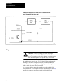
CAUTION: Output devices on either module can be of any
voltage, up to 30V DC, provided an external load power supply
is used and wired according to figure 8. However, the maximum
current through either output is 500mA and should not be
exceeded, otherwise damage to the module may occur.
With loads that have inductive characteristics, such as relays or solenoids,
connect an external supression device across the terminals of the load.
Inductive loads may result in damage to the module if suppression devices
are not used.
Programming
The module uses four words of data to communicate with the processor.
Three words, the control word and two preset values, are sent from the
processor to the modules as output words and one, the status word, is
returned as an input word. The following discussion explains the function
of the control bits. Although the information conveyed in the output words
is the same, the format varies between single transfer and block transfer.
Refer to figures 6 and 7 for specific location of the bits. Further
programming information describing block transfer and single transfer
applications is available in the Encoder/Counter Module User’s Manual
(publication 1771-807).
11
Product Data
Encoder/Counter Module
Output Word Select
Single Transfer Programming Word Select (Bits 14, 15,16, and 17) — In
single transfer programming, since each of the three output words is sent to
the module through the single output image table word, each output word
must be labeled so the module can identify which word it is receiving. For
example, bit 17 is set for the output control word. Bit 16 is set to identify
the preset 1 word; bit 15 is set to identify the preset 2 word (figure 6).
Figure 6
Single Transfer Input and Output Words
12
Product Data
Encoder/Counter Module
Since block transfer moves words of data simultaneously, rather than one
at a time, there is no need to label which word of data is being transferred.
Therefore, it is not necessary to distinguish the control word and each of
the preset words (figure 7).
For block transfer, the module will identify the output words by their order
in the data table. The control word must always be the first word in the
block of data, followed immediately by the preset 1 word, then the preset 2
word. Since the module uses bidirectional block transfer, you must develop
the appropriate programming for the input status word, and assign a
location to it in the data table.
Figure 7
Block Transfer Input and Output Words
13
Product Data
Encoder/Counter Module
Output Control Bits
Comparisons for Output 1 — Setting one or more of these bits defines the
onboard comparison between the accumulated and preset 1 values (figures
6 and 7). Whenever the comparison is true, output 1 will turn on. For
example, if bits 01 and 02 in single transfer are set, then output 1 is
energized when the accumulated number of pulses (in either the encoder or
counter mode) is equal to or greater than the preset value as sent from the
processor in preset 1 output word. Note that in block transfer the
comparison value is in the corresponding preset word.
Comparisons for Output 2 — Setting one or more of these bits defines the
comparison between the accumulated and preset 2 values. Whenever the
comparison is true, output 2 will turn on. For example, if bits 04 and 05 in
single transfer are set, then output 2 is energized when the accumulated
number of pulses (in either the encoder or counter mode) is equal to or
greater than the preset value that was sent from the processor in preset 2
output word.
Home Latch Enable — This bit must be set and the marker and limit
switch inputs must be high (on) for the home bit in the input status word to
be set. The counter resets and remains reset as long as the home latch
enable, marker, and limit switch signals are all true. You can set the home
latch enable bit from the program by comparing the accumulated value in
the status word with some fixed value in the program, or you can set it
from some external device. This allows the processor to ignore the marker
signal until it is close to home. The home bit works in either the encoder or
counter mode. Once set, the home bit remains set until the home latch
enable bit is reset.
Function Control — These bits determine when the module will count or
be reset. They operate in either the encoder or counter mode. Notice that
both bits cannot be set at the same time.
Single Transfer
Bit Number
14
Description
Block Transfer
Bit Number
11
10
01
00
0
0
Count
0
0
0
1
Reset, and hold the
accumulated count at zero.
0
1
0
Return the accumulated
count to zero and begin
counting immediately
1
0
1
1
Invalid, module retains
previously programmed
function.
1
1
Product Data
Encoder/Counter Module
Enable Outputs — This bit must be set for the outputs to be energized.
Resetting this bit to zero de-energizes both outputs.
Count Direction — This bit is functional only when the module is in the
counter mode. The count direction bit must be set for the module to count
up. If it is reset, the module will count down. If external count direction
from a device wired to channel B is used, then the count direction bit must
be set.
Bits 06 and 14 of the control word in single transfer are not used. They
have no effect on module operation.
In block transfer, bits 5 through 17 of the control word and bit 14 in the
preset words are not used. They have no effect on module operation.
Output Preset Values
There are two preset words; each one functions using the appropriate
comparison selected in the control word. When the accumulated value is
within the limits defined by the control word, the corresponding output is
energized, provided the output enable bit is set.
The lower twelve bits of each preset word contain the preset value. If the
programming option switch is set for BCD, then these bits contain the
value as a binary coded decimal (999 max). If a non-valid BCD code is
inserted into one of the 4 bit BCD groups, the module resets the entire
value to 000. If you set the switch for binary, the module will interpret the
lower twelve bits as a binary number. The input status word contains the
accumulated value in binary if binary count mode is selected. The
maximum number you can insert in binary is 4095.
In single transfer, bit 16 is set to identify the preset 1 word. Bit 15 is set to
identify the preset 2 word. All other unassigned bits must be zero.
Input Status Word
When you select single transfer, the input status word appears in the input
image table at the module’s address. You can monitor the input status word
from that location or shift it elsewhere in the data table. The format is the
same for block transfer and single transfer.
The lower twelve bits (bits 00 to 13) contain the accumulated value as it is
stored in the module’s memory at the time of the transfer. Since the speed
of the transfer is dependent on scan time, the accumulated value as it
appears at the processor may not be the actual count at the module. If high
speed decisions must be performed, the comparisons established in the
control word that will energize the hardwired output of the module allow a
very fast response by the control system.
15
Product Data
Encoder/Counter Module
Diagnostic (Bit 14) — If this bit is set, it means that the module has
detected a fault in its internal processes. If the diagnostic LED is
illuminated, bit 14 is also set. This bit should be monitored in the program
to signal the operator if there is a fault.
Borrow (Bit 15) — This bit indicates that the accumulated value, when
counting down, has reached zero and decremented once more. As this bit is
set, the count changes to 999 in BCD, or 4095 in binary. You can use the
borrow bit to cascade counters in the program to register a much larger
count than that kept on the module. This bit remains set until the count
reaches zero again and is decremented once, at which time it toggles back
to zero. The bit continues changing state as long as the count decrements
past zero. The bit resets anytime the module is powered-up. It cannot be
reset from the function control bits or from setting the home bit.
Carry (Bit 16) — This bit indicates that the accumulated value, as kept on
the module, has counted past the maximum value of the data format (999
in BCD or 4095 in binary). As this bit is set, the module increments past
zero and continues counting. Use the carry bit to cascade counters in the
program to register a much larger count than that kept on the module. This
bit remains set until the count reaches the maximum again, at which time
the carry bit and the accumulated value are reset. This bit continues
changing state as long as the count keeps cycling past its maximum value.
The bit resets at power-up. It cannot be reset from the function control bits
or from setting the home bit.
NOTE: The cycling of the carry or borrow bit should be long enough to be
detected by the program. Since the program scan time is application
dependent, no specific values can be given. However, the carry or borrow
bit will toggle at 1/1000 the frequency of the input pulses (in BCD) at a
times 1 count resolution setting. The reciprocal of this value, that is the
period of time the carry or borrow bit is in its on or off state, should be
longer than the program scan plus any I/O update time. With the count
resolution set for times 2 or times 4, or with a long program, you may find
it necessary to request the input status word several times during the
program scan with immediate I/O instructions (not available on the PLC or
PLC-3 processors).
Home (Bit 17) — The home bit is set whenever the marker input is high,
the limit switch input detects a true voltage, and the home latch enable bit
in the control word is set. This allows the control system to establish a
reference point, or home position. The accumulated count is also reset to
zero and held there until either the marker or the limit switch inputs return
to a logic 0 state. The module will then begin counting again from zero.
However, the home bit remains set, even if the marker or limit switch is
reset, until the home latch enable bit in the control word is reset. This
permits the processor to detect the home bit, even if the marker signal is
very short. The home latch enable bit can be toggled in the program if
necessary to turn off the home bit.
16
Product Data
Encoder/Counter Module
System Power
System power is supplied through the I/O chassis backplane from the
associated I/O chassis power supply. The 1771-IJ or 1771-IK module
requires a current of 1.4A from the 5V DC output of this supply (table B).
Add the module current to the current requirements of other modules in the
I/O chassis to avoid overloading the supply or backplane of the I/O chassis.
Table B
Power Requirements
System Power
External Power
External Power
Requirements
Module
Current from
+5V DC circuit
Current
Required
Voltage
Required
Ripple
1771lJ
1.4A
140mA
+5V DC
50mV pp max
1771IK
1.4A
110mA
200 mA
+12V DC
+24V DC
50mV pp max
50mV pp max
The module requires an external power supply connected to the field
wiring arm. For the 1771-IJ module, the supply must be able to deliver
140mA at 5V DC with less than 50mV ripple, peak-to-peak (table B). The
1771-IK module requires 110mA at 12V DC or 200mA at 24V DC, with
less than 50mV ripple, peak-to-peak. These requirements are for the
module only. You must add the current requirements of all output devices,
if they are to be driven directly from the module, to the current
requirements of the module.
It is also possible to drive output devices from a separate load supply, using
the output on the module only as a switch (figure 8). When the output is on
and conducting, a maximum of 0.5V DC is dropped across it. The load
supply voltage should not exceed 30V DC.
The module’s external power supply can provide power for the input
device, but, unlike the power for the output device, this is not available
through the module. If a high degree of isolation is needed, use a separate
input power supply (figures 9 and 10).
If the limit switch is used, the limit switch input is configured to accept an
on voltage of 12V to 48V DC, requiring a maximum of 10mA at 48V DC.
17
Product Data
Encoder/Counter Module
Figure 8
Modification of Output Circuit for Application of Separate Loads Power
Supply (Terminals on Right Swing Arm)
Wiring
WARNING: Remove system power before removing or
installing your module in the 1771 I/O chassis. Failure to
observe this warning could result in damage to module circuitry
and/or undesired operation with possible injury to personnel.
The module can be placed in any 1771 I/O chassis. However, the module
must only be inserted in a single module group; it cannot straddle two
groups. To minimize noise, group low voltage input modules together
within a single I/O chassis whenever possible.
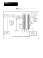
Use the proper cable to connect the input devices to the module’s field
wiring arm. Follow the appropriate connection diagram (figures 9 and 10).
Input devices cannot be more than 40 cable feet from the module.
18
Product Data
Encoder/Counter Module
Belden 8761 cable can be used for counter applications with a signal below
20kHz. Belden 8725 cable is a 4-twisted pair cable recommended for
encoder applications below 20kHz. Belden 9182 cable is recommended to
50kHz. You may use cables equivalent to those above.
Figure 9
Connection Diagram Showing Typical 1771IJ Encoder Application
19
Product Data
Encoder/Counter Module
Figure 10
Connection Diagram Showing Typical 1771IK Counter Applications with
External Count Directions
20
Product Data
Encoder/Counter Module
Refer to figure 11. Belden 9182 cable has a foil shield with a bare drain
wire. Connect the drain wire to enclosure ground at an I/O chassis
mounting bolt or stud. However, do not cut back more than two inches
from the cable ends. Connect only one end of the cable ground. The foil
and drain at the other end of the cable, which connects to the device,
should be cut short and taped back to insulate it from any electrical
contact.
Figure 11
Wiring of Shield to Chassis
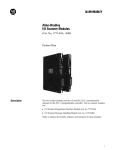
Keying
The encoder/counter module is keyed to allow you to guard against
installation into a slot keyed for another module type. To implement this
protection, you must key the I/O chassis backplane connectors by inserting
the keying bands supplied with the I/O chassis assembly.
Because the module uses two slots, you should key both slots (figure 12).
Snap the keying bands on the upper backplane connectors between these
numbers printed on the backplane. The keying is different for the 1771-IJ
and the 1771-IK modules:
21
Product Data
Encoder/Counter Module
Left Connector
Right Connector
1771IJ
6 and 8
18 and 20
4 and 6
32 and 34
1771_IK
6 and 8
8 and 22
4 and 6
32 and 34
You can change the position of the these keying bands if subsequent
system design and rewiring makes insertion of a different type of module
necessary.
Figure 12
Keying Positions
22
Product Data
Encoder/Counter Module
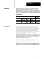
Specifications
Counters per Module
G 1
Counter Input (Switch Selectable)
G Single Channel (Counter)
G Duel Channel (Encoder)
Input Pulse Rate
G 50kHz max Data Transfer Modes (Switch
Selectable)
Single Transfer Mode
G Block Transfer Mode
Power Supply 5V Current Requirements
G 1.2Atypical
G 1.4A (max)
Electrical Isolation
G 1500V RMS (transient)
TTL Input Ratings (1771lJ)
G Input Current per Channel: Encoder or
counter device should be able to sink 16mA
G input Voltage: VI H = 2.4V (min)
VI H = 0.6V(max)
1224V Input Ratings (1771IK)
G Input Current per Channel: Encoder or
counter device should be able to sink 10mA
at 12V, and 20mA at 24V
G V Input for 12V (Customer supply):
High = 8.0V (min), Low = 4.0V (max)
G V Input for 24V (Customer supply):
High = 16.0V (min), Low = 8.0V (max)
Output Ratings
G Output Current: I (max) = 500mA per output
(open collector outputs without internal
pullup resistors)
G Output Voltage: V(output high) = 30.0 volts
(max with external pullup); V(output low) 0.5
volts max @ 500mA
Customer Supply
G 5V DC "0.25 @ 140mA max (1771IJ)
G 12V @ 110mA (1771IK)
G 24V @ 200mA (1771IK)
G 50mV pp ripple max
Ambient Temperature Rating
G Operational: 0° to 60°C (32° to 140°F)
G Storage: -40° to 85°C (-40° to 185°F)
Relative Humidity
G 5% to 95% (without condensation)
Keying
G See text.
23
Product Data
Encoder/Counter Module
With offices in major cities worldwide
WORLD
HEADQUARTERS
Allen-Bradley
1201 South Second Street
Milwaukee, WI 53204 USA
Tel: (1) 414 382-2000
Telex: 43 11 016
FAX: (1) 414 382-4444
EUROPE/MIDDLE
EAST/AFRICA
HEADQUARTERS
Allen-Bradley Europe B.V.
Amsterdamseweg 15
1422 AC Uithoorn
The Netherlands
Tel: (31) 2975/43500
Telex: (844) 18042
FAX: (31) 2975/60222
Publications 1771-2.21 — December, 1983
Supersedes Publication 1771-928 — January, 1981
24
As a subsidiary of Rockwell International, one of the world’s largest technology
companies — Allen-Bradley meets today’s challenges of industrial automation with over
85 years of practical plant-floor experience. More than 11,000 employees throughout the
world design, manufacture and apply a wide range of control and automation products
and supporting services to help our customers continuously improve quality, productivity
and time to market. These products and services not only control individual machines but
integrate the manufacturing process, while providing access to vital plant floor data that
can be used to support decision-making throughout the enterprise.
ASIA/PACIFIC
HEADQUARTERS
Allen-Bradley (Hong Kong)
Limited
Room 1006, Block B, Sea
View Estate
28 Watson Road
Hong Kong
Tel: (852) 887-4788
Telex: (780) 64347
FAX: (852) 510-9436
CANADA
HEADQUARTERS
Allen-Bradley Canada
Limited
135 Dundas Street
Cambridge, Ontario N1R
5X1
Canada
Tel: (1) 519 623-1810
FAX: (1) 519 623-8930
LATIN AMERICA
HEADQUARTERS
Allen-Bradley
1201 South Second Street
Milwaukee, WI 53204 USA
Tel: (1) 414 382-2000
Telex: 43 11 016
FAX: (1) 414 382-2400
PN 955093-79
Copyright 1983 Allen-Bradley Company, Inc. Printed in USA