1
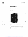
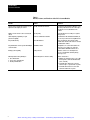
Artisan Technology Group is your source for quality
new and certified-used/pre-owned equipment
• FAST SHIPPING AND
DELIVERY
• TENS OF THOUSANDS OF
IN-STOCK ITEMS
• EQUIPMENT DEMOS
• HUNDREDS OF
MANUFACTURERS
SUPPORTED
• LEASING/MONTHLY
RENTALS
• ITAR CERTIFIED
SECURE ASSET SOLUTIONS
SERVICE CENTER REPAIRS
Experienced engineers and technicians on staff
at our full-service, in-house repair center
WE BUY USED EQUIPMENT
Sell your excess, underutilized, and idle used equipment
We also offer credit for buy-backs and trade-ins
www.artisantg.com/WeBuyEquipment
InstraView REMOTE INSPECTION
LOOKING FOR MORE INFORMATION?
Visit us on the web at www.artisantg.com for more
information on price quotations, drivers, technical
specifications, manuals, and documentation
SM
Remotely inspect equipment before purchasing with
our interactive website at www.instraview.com
Contact us: (888) 88-SOURCE | [email protected] | www.artisantg.com
Product Data
I/O Scanner Modules
AllenBradley
I/O Scanner Modules
(Cat. No. 1775-S4A, -S4B)
Product Data
Description
The I/O scanner modules provide I/O and RS-232-C communication
channels for the PLC-3 programmable controller. The two scanner modules
are:
I/O Scanner-Programmer Interface Module (cat. no.1775-S4A
I/O Scanner-Message Handling Module (cat. no. 1775-S4B)
Table A outlines the benefits, features, and functions for these modules.
1
Artisan Technology Group - Quality Instrumentation ... Guaranteed | (888) 88-SOURCE | www.artisantg.com
Product Data
I/O Scanner Modules
Table A
Benefits, Features, and Functions of the PLC3 Scanner Modules
Benefits
Features
Functions
High speed I/O communication with up to 2,048
inputs and 2,048 outputs per scanner
Four I/O communication channels
Communicate with I/O Adapter Modules (cat no
1771AS) in I/O chassis You can connect up to
16 I/O chassis to one I/O channel on the
scanner
Ability to execute a faster scan for selected I/O
chassis
I/O scan priority
Scan the I/O chassis according to a sequence
that you select
Ladder diagram programming or report
generation capability
RS232C communication channel
Communicates with an Industrial Terminal (cat
no 1770T4) or an RS232C compatible device
Easy troubleshooting
Status LED indicators
Keep you informed of the general scanner
module status and the active status of each I/O
communication channel
Easy identification of PLC3 system with multiple Thumbwheel switch
scanner modules
Distinguishes one scanner from another The
PLC3 processor requires one 1775S4A
scanner with its thumbwheel switch set to 1
Backup system capability
Backup connector
Transfers control over to a backup PLC3
processor if a fault shuts down the primary
PLC3 processor
Efficient production floor planning for:
Terminal swing arm for extensive cabling
Makes connections to:
G I/O communication
G Peertopeer communication
G Backup communication
G Bulletin 1771 I/O chassis up to 10,000 cable
feet away from scanner via Twinaxial Cable
(cat no 1770CD)
G Communication channels on 1775S4A
scanners in up to 6 separate PLC3 systems
G Communication channel on a 1775S4A
scanner in another PLC3 system
2
Artisan Technology Group - Quality Instrumentation ... Guaranteed | (888) 88-SOURCE | www.artisantg.com
Product Data
I/O Scanner Modules
The following two sections of this publication explain the functional
differences between the 1775-S4A scanner and the 1775-S4B scanner.
These differences are summarized in table B. This publication also
explains the hardware components on the scanners.
Table B
Functional Differences Between 1775S4A and 1775S4B Scanners
Type of Scanner
Function
Number
One
1775S4A
Another
1775S4A
1775S4B
Required for PLC3 processor operation
Yes
No
No
I/O Scanning with four I/O channels
Yes
Yes
Yes
Backup or peertopeer communication capability
Yes
Yes
No
Required for PLC3 backup operation
Yes
No
No
Programming interface with channel 5
Yes1
Yes
No
Programming interface with channel 0 on PLC3
front panel
Yes
No
No
Report generation interface with channel 5
No
No
Yes
1 To Operate channel 5 on the number one 1775S4A scanner you must make I/O channel 4
inactive through the PLC3 LIST function.
You can find detailed information on these scanners in:
I/O Scanner-Programmer Interface Module User’s Manual (publication
1775-6.5.2, formerly 1775-805)
I/O Scanner-Message Handling Module User’s Manual (publication
1775-6.5.3, formerly 1775-806)
Using the 1775S4A Scanner
The 1775-S4A scanner is a required module for the PLC-3 programmable
controller. When you are setting up your PLC-3 system, you must insert a
1775-S4A scanner into the PLC-3 Main Processor Chassis (cat. no.
1775-A1) and set its thumbwheel switch to one. This number one
1775-S4A scanner communicates between the PLC-3 programmable
controller and:
the industrial terminal for programming interface
1771I/O chassis for I/O scanning interface
a backup PLC-3 processor that takes control over the outputs if the
primary PLC-3 processor faults
up to six PLC-3 processors for peer-to-peer communication
3
Artisan Technology Group - Quality Instrumentation ... Guaranteed | (888) 88-SOURCE | www.artisantg.com
Product Data
I/O Scanner Modules
Programming Interface
The 1775-S4A scanner provides an RS-232-C compatible channel (channel
5) that can communicate with the industrial terminal. You can use the
industrial terminal to:
enter and monitor ladder diagram program instructions
enter and monitor data table values
force inputs and outputs
operate the PLC-3 LIST function
load and record ladder diagram programs with a Data Cartridge
Recorder (cat. no. 1770-SB) or Data Cassette Recorder (cat. no.
1770-SA)
print out ladder diagram program through channel C interface to a
printer
The number one 1775-S4A scanner supports operation of channel 0 on the
PLC-3 front panel. If you are using channel 5 on the number one
1775-S4A scanner, you must make I/O channel 4 inactive through the
PLC-3 LIST function.
Additionally, through LIST selections for the number one 1775-S4A
scanner, you can configure channel 0 on the PLC-3 front panel for
communication with the industrial terminal or an RS-232-C compatible
device.
I/O Scanning Interface
The 1775-S4A scanner provides terminals for four separate I/O
communication channels. These channels can communicate with I/O
adapter modules in I/O chassis. In scanning these I/O channels, the
1775-S4A scanner:
reads the status of output image table words from the data table and
transmits this data to update the status of the terminals on the
corresponding output module groups
receives the status from the terminals on the input module groups and
writes this data into the corresponding input image table word in the
data table
You can connect up to 16 I/O chassis on a single I/O channel. Through the
PLC-3 LIST function, you can select the sequence that the 1775-S4A
scanner scans the I/O chassis. If an I/O chassis requires a faster update
time, you can list the chassis more than once in the sequence.
4
Artisan Technology Group - Quality Instrumentation ... Guaranteed | (888) 88-SOURCE | www.artisantg.com
Product Data
I/O Scanner Modules
Backup Communication
Through LIST selections for the 1775-S4A scanner, you can configure an
I/O channel for a backup communication function. In operating this
function, the I/O channel of a 1775-S4A scanner in the primary PLC-3
processor is connected to the same channel of a 1775-S4A scanner in the
backup PLC-3 processor. An input file receives data from the backup
processor. An output file sends data to the backup processor.
By cabling between the connectors labeled BACK UP on a number one
1775-S4A scanner in the primary PLC-3 processor chassis and a number
one 1775-S4A scanner in the backup PLC-3 processor chassis, you can set
up a PLC-3 backup system. In this system, if a fault disables the PLC-3
processor, the second PLC-3 processor can take control of the outputs. For
detailed information on the PLC-3 backup system, refer to the PLC-3
Programmable Controller Backup Concepts Manual (publication
1775-6.3.1, formerly 1775-803).
PeertoPeer Communication
Through LIST selections for the 1775-S4A scanner, you can configure an
I/O channel for peer-to-peer communication. In this function, you connect
the I/O channel of a 1775-S4A scanner in one PLC-3 processor to the same
channel of a 1775-S4A scanner in each of up to 6 PLC-3 processors. You
must designate one PLC-3 processor as the master of this communication
channel. The other PLC-3 processors on the channel act as slaves.
In peer-to-peer communication, the master communicates with each slave.
Through the LIST function you select a separate file in the master PLC-3
processor for each slave. This file is the source for data that transfers to the
slave PLC-3 processor(s). You also select a file in each slave PLC-3
processor that receives the data.
Peer-to-peer communication allows PLC-3 processors to exchange data
such as part counts and production status information.
Additional 1775S4A Scanners
You can add up to 14 additional 1775-S4A scanners for additional I/O
communication and RS-232-C capability. Each additional 1775-S4A
scanner provides four I/O communication channels and a RS-232-C
communication channel.
5
Artisan Technology Group - Quality Instrumentation ... Guaranteed | (888) 88-SOURCE | www.artisantg.com
Product Data
I/O Scanner Modules
Using the 1775S4B Scanner
The 1775-S4B scanner is an optional module for the PLC-3 programmable
controller. The 1775-S4B scanner communications between the PLC-3
programmable controller and:
RS-232-C compatible devices for report generation interface
1771 I/O chassis for I/O scanning interface
Report Generation Interfaces
The 1775-S4B scanner provides an RS-232-C compatible channel (channel
5) that can communicate with data terminals, computers, printers, modems,
and other RS-232-C compatible devices. You can use these devices to
program in the report generation language available with the 1775-S4B
scanner.
By using the report generation language, you can enter and store messages
from the data terminal. You can execute these messages through the data
terminal or by using the MSG instruction in the ladder diagram program.
Report generation allows you to format text and data for display on a CRT
screen or printer. You can also display graphic presentations on a CRT
screen.
I/O Scanning Interface
The 1775-S4B scanner has terminals for four separate I/O communication
channels. You can use these channels for I/O scanning the same as the
1775-S4A scanner.
Looking at the PLC3 Scanner
Modules
Both scanner modules have the following hardware components (figure 1):
self-test indicators
thumbwheel switch
status indicators for the I/O channels
backup connector
channel 5 connector
terminal swing arm
We describe these components in the following sections.
6
Artisan Technology Group - Quality Instrumentation ... Guaranteed | (888) 88-SOURCE | www.artisantg.com
Product Data
I/O Scanner Modules
Figure 1
Hardware Features on the PLC3 Scanner Modules
Selftest Indicators
At the top of the scanner’s front edge, LED indicators labeled PASS and
FAIL keep you informed on the general condition of the scanner. These
indicators have the following meanings:
PASS (green)
FAIL (red)
Meaning
On
Off
On
Off
Off
On
On
Off
Normal operation
Module fault
Powerup or system reset
PLC3 processor is
turned off
Thumbwheel Switch
The thumbwheel switch is below the self-test indicators. Setting it at a
unique number (1 to 15) enables the PLC-3 processor to distinguish one
scanner from another. That is, a 1775-S4A scanner and a 1775-S4B
scanner in the PLC-3 processor chassis can be set at the same number.
CAUTION: Do not change the thumbwheel setting on a
scanner module while PLC-3 processor power is on. Equipment
damage could result.
7
Artisan Technology Group - Quality Instrumentation ... Guaranteed | (888) 88-SOURCE | www.artisantg.com
Product Data
I/O Scanner Modules
Remember, you must have a 1775-S4A scanner with its thumbwheel
switch set at 1 in the PLC-3 main processor chassis.
I/O Channel Status Indicators
Below the thumbwheel switch are four green LEDs labeled:
CH1
CH2
CH3
CH4
Each LED corresponds to one of the four I/O communication channels.
Depending on your use for the I/O communication channel, each indicator
has the following meanings:
If you are using the channel for I/O scanning with a 1775-S4A or
1775-S4B scanner:
If the LED is:
Then:
On
Communication between the scanner module and the I/O chassis on the
corresponding I/O channel is properly established
Flashing
There is a fault on one or more of the I/O chassis on the corresponding I/O
channel
Off
No I/O chassis are connected to the corresponding I/O channel or the channel is
inactive
If you are using the channel for peer to peer communication with
1775-S4A scanners:
If the LED is:
Then:
On
The channel is functioning properly.
Flashing
The in put file that receives the data from a slave PLC3 processor is too small.
Off
There is a communication problem along the channel or the channel is inactive.
If you are using the channel for backup communication with 1775-S4A
scanners:
If the LED is:
Then:
The channel is functioning properly.
Flashing
The input file that receives the data from the backup PLC3 processor is too
small.
Off
The channel has not received data during the last 200ms or the channel is
inactive.
8
Artisan Technology Group - Quality Instrumentation ... Guaranteed | (888) 88-SOURCE | www.artisantg.com
Product Data
I/O Scanner Modules
Backup Connector
Below the I/O channel status indicators is a backup connector. You can use
this connector to set up the backup system capability for switching control
over the outputs. This connector is only used for 1775-S4A scanner
number one.
Channel 5 Connector
Below the backup connector is a 25-pin D-shell connector labeled CH5.
This connector provides communication with:
an industrial terminal for ladder diagram programming and configuring
the PLC-3 system if you are using a 1775-S4A scanner
an RS-232-C compatible device for report generation if you are using a
1775-S4B scanner
To use channel 5 on 1775-S4A scanner number one, you must make I/O
channel 4 inactive through the PLC-3 LIST function.
Terminal Arm Swing
Near the bottom of the scanner module is a Terminal Swing Arm (cat. no.
1775-WA). This swing arm contains the connection for I/O communication
channels 1 to 4. Functions of these channels include:
Function
Compatibility
Scanning I/O
1775S4A or 1775S4B scanners
Peer to peer communication
1775S4A scanner only
Backup communication
1775S4A scanner only
Electrostatic Discharge
Under some conditions, electrostatic discharge can degrade performance or
damage an I/O scanner module. If you observe the following precautions
you can guard against electrostatic damage.
Touch a grounded object to discharge yourself before handling the
module.
Do not touch the backplane connector or connector pins.
When not in use, keep the module in its static-shield bag.
9
Artisan Technology Group - Quality Instrumentation ... Guaranteed | (888) 88-SOURCE | www.artisantg.com
Product Data
I/O Scanner Modules
Specifications
Location
G Single slot in a PLC3 processor chassis
Functions
G I/O interface
G RS232C interface for ladder diagram
programming
G RS232C interface for report generation
I/O Capacity
G 2,048 inputs and 2,048 outputs
Channels Per Scanner
G 4 I/O communication
G 1 RS232C communication
Communication Rate
G 57.6 or 115.2 kbaud (I/O channel)
G 110 baud to 19.2 kbaud
(RS232C channel)
I/O Channel Cable Length
G 10,000 cable feet (max)
Nominal I/O Scan Times Per I/O Adapter
G 5.5 to 6.5ms for 1 channel
G 6ms for 2 channels
G 6ms for 3 channels
G 6.0 to 6.5ms for 4 channels
Environmental Conditions
G Operational Temperature:
0 to 60° C (32 to 140° F)
G Storage Temperature:
40 to 85°C (40 to 185° F)
G Relative Humidity:
5 to 95% (without condensation)
With offices in major cities worldwide
WORLD
HEADQUARTERS
Allen-Bradley
1201 South Second Street
Milwaukee, WI 53204 USA
Tel: (1) 414 382-2000
Telex: 43 11 016
FAX: (1) 414 382-4444
EUROPE/MIDDLE
EAST/AFRICA
HEADQUARTERS
Allen-Bradley Europe B.V.
Amsterdamseweg 15
1422 AC Uithoorn
The Netherlands
Tel: (31) 2975/43500
Telex: (844) 18042
FAX: (31) 2975/60222
Publication 1775-2.5 — October, 1984
Supersedes Publication 1775-906 — May, 1982
As a subsidiary of Rockwell International, one of the world’s largest technology
companies — Allen-Bradley meets today’s challenges of industrial automation with over
85 years of practical plant-floor experience. More than 11,000 employees throughout the
world design, manufacture and apply a wide range of control and automation products
and supporting services to help our customers continuously improve quality, productivity
and time to market. These products and services not only control individual machines but
integrate the manufacturing process, while providing access to vital plant floor data that
can be used to support decision-making throughout the enterprise.
ASIA/PACIFIC
HEADQUARTERS
Allen-Bradley (Hong Kong)
Limited
Room 1006, Block B, Sea
View Estate
28 Watson Road
Hong Kong
Tel: (852) 887-4788
Telex: (780) 64347
FAX: (852) 510-9436
CANADA
HEADQUARTERS
Allen-Bradley Canada
Limited
135 Dundas Street
Cambridge, Ontario N1R
5X1
Canada
Tel: (1) 519 623-1810
FAX: (1) 519 623-8930
LATIN AMERICA
HEADQUARTERS
Allen-Bradley
1201 South Second Street
Milwaukee, WI 53204 USA
Tel: (1) 414 382-2000
Telex: 43 11 016
FAX: (1) 414 382-2400
PLC is a registered trademark of Allen-Bradley Company
Copyright 1984 Allen-Bradley Company, Inc. Printed in USA
10
Artisan Technology Group - Quality Instrumentation ... Guaranteed | (888) 88-SOURCE | www.artisantg.com
Artisan Technology Group is your source for quality
new and certified-used/pre-owned equipment
• FAST SHIPPING AND
DELIVERY
• TENS OF THOUSANDS OF
IN-STOCK ITEMS
• EQUIPMENT DEMOS
• HUNDREDS OF
MANUFACTURERS
SUPPORTED
• LEASING/MONTHLY
RENTALS
• ITAR CERTIFIED
SECURE ASSET SOLUTIONS
SERVICE CENTER REPAIRS
Experienced engineers and technicians on staff
at our full-service, in-house repair center
WE BUY USED EQUIPMENT
Sell your excess, underutilized, and idle used equipment
We also offer credit for buy-backs and trade-ins
www.artisantg.com/WeBuyEquipment
InstraView REMOTE INSPECTION
LOOKING FOR MORE INFORMATION?
Visit us on the web at www.artisantg.com for more
information on price quotations, drivers, technical
specifications, manuals, and documentation
SM
Remotely inspect equipment before purchasing with
our interactive website at www.instraview.com
Contact us: (888) 88-SOURCE | [email protected] | www.artisantg.com