1
Bachelor’s Thesis
Degree Programme in Information Technology
2010
NI ZE
Electronic Photo Frame
ii
BACHELOR´S THESIS | ABSTRACT
UNIVERSITY OF APPLIED SCIENCES
Degree Programme in Information Technology
Spring 2010 | 56
Vesa Slotte
Ni Ze
Abstract
The goal of the thesis work is to develop a photo frame device.
Hence, it
supplies a set of feasible solutions from hardware to software. Relatively
speaking, the project chiefly focuses on software-oriented development. It is
concerned with building the bootloader, the Linux Kernel, related drivers, file
systems, and applications. After that, they are integrated together to form a
brand-new embedded Linux distribution. The distribution is specifically designed
to meet the requirement of the photo frame device. In contrast with complex
software, the hardware implement is simply based on ready-made development
board GEC2410. According to the actual need of the project, unnecessary
components can be cut off logically. Lastly, the photo frame device implements
the basic image browsing and manipulating functions as well as USB support.
iii
Contents
Abstract ............................................................................................................................................... ii
Contents ............................................................................................................................................. iii
Notation .............................................................................................................................................. iv
1. Introduction .................................................................................................................................... 1
2. Hardware description.................................................................................................................... 3
2.1 Embedded processor architectures ..................................................................................... 3
2.2 Storage devices....................................................................................................................... 4
2.3 Electronic photo frame requirements ................................................................................... 5
3. Main software description ............................................................................................................ 7
3.1 GNU Cross-Platform Development Toolchain .................................................................... 7
3.2 Bootloader .............................................................................................................................. 10
3.3 Busybox...................................................................................................................................11
3.4 Tslib ..........................................................................................................................................11
3.5 Qt ..............................................................................................................................................11
3.6 Qt Embedded ........................................................................................................................ 12
4. Developing Flow .......................................................................................................................... 13
4.1 Host machine environment.................................................................................................. 13
4.2 Cross-platform Toolchain building ...................................................................................... 13
4.3 Embedded Linux Kernel building ........................................................................................ 15
4.3.1 Nand Flash driver .......................................................................................................... 16
4.3.2 CS8900 driver ................................................................................................................ 17
4.3.3 LCD driver....................................................................................................................... 18
4.3.4 Touchscreen driver ........................................................................................................ 21
4.3.5 USB driver ...................................................................................................................... 22
4.3.6 Kernel configuration ...................................................................................................... 23
4.4 Embedded Linux file system building ................................................................................ 24
4.5 Configuring the TFTP server in the host machine ........................................................... 27
4.6 Configuring the NFS server in the host machine ............................................................. 28
4.7 Bootloader Porting ................................................................................................................ 28
4.8 Kernel startup testing and root file system mounting by NFS ........................................ 29
4.9 Tslib building .......................................................................................................................... 30
4.10 Qt Embedded building ....................................................................................................... 32
4.11 Photo frame application development and porting ........................................................ 33
4.12 Reprogramming gec2410-bios into the Flash device.................................................... 34
4.13 Embedded Linux kernel porting ........................................................................................ 35
4.14 Building the root file system image and porting ............................................................. 36
4.15 Testing and debugging the whole product ...................................................................... 37
Appendix A: GNU Binutils Illustration ........................................................................................... 41
Appendix B: LCD initial functions .................................................................................................. 42
Appendix C: The implementation of slide show .......................................................................... 48
iv
Notation
CLFS
Cross Linux from Scratch
EEPROM
Electrically Erasable Programmable Read-Only Memory
GNU
Gnu's Not Unix
IIC
Inter Integrated Circuit
JTAG
Joint Test Action Group
1
1. Introduction
As embedded industry is gradually blooming, more and more embedded
products appear in the current electronic consumption market. The electronic
photo frame device is one of the most popular embedded products. This project
aims to provide a set of precise and detailed implementation of the photo frame
device. The implementation can be divided into two aspects: hardware and
software. On the hardware side, the photo frame in the project is applied on the
GEC2410 hardware platform. GEC2410 is designed by integrating S3C2410 and
a few common interfaces like USB devices, Ethernet port, Serial port, SD/MMC.
However, not all the components need be involved in the photo frame. For this
reason, a part of the components are certainly removed hypothetically such as
Audio ports, SD, LED devices and so on. This means that unnecessary
components still exist on the development board but, in fact, they are not used in
the project at all. They are just ignored, in theory. On the software side, the photo
frame is built on the Linux platform. The reason for select the Linux platform is
because
Linux can have strong support for different architectures, especially
for ARM architecture, like GEC2410. Taking into account of the problem of
limited hardware resources on the development board, most
software
developments need to be operated on the PC, as usual. To be exact, we refer to
the PC platform as host machine in comparison with the development board
which is referred to as target machine. Generally, these two machines are based
on different architectures. In practice, however, developed programs based on
X86 architecture cannot be executed on the ARM architecture. That is the
reason why the cross-platform development toolchain is built as the first step of
development. In addition to that toolchain, the following chapters state various
approaches to bootloader setting, Linux Kernel selection and building, root file
system building, and applications development. Then, they are combined
together to build
a custom Linux operating system. In such an operating
system, there is functional image software provided for the photo frame device to
2
view pictures. Lastly, the bootloader image, the Linux Kernel image, and file
system image are ported into the target machine. And thus, the photo frame
device can work independently.
3
2. Hardware description
2.1 Embedded processor architectures
X86
The x86-architecture has been designed and produced by Intel since 1985.
Nowadays, the x86 processor is the most widely used and tested Linux platform.
Many applications and add-ons are firstly released on the x86-based
architecture. Furthermore, the X86-architecture is the most widely documented
architectures around. However, it still possesses a small share in the transitional
embedded system market. The reason is that the embedded system is limited to
hardware resources and it needs more efficient and flexible processing
instruction sets. [1]
ARM
The ARM, which stands for Advanced RISC Machine, is a family of processors
maintained and promoted by ARM Holding Ltd [2]. In this project, the core board
of GEC2410 is S3C2410 that is applied ARM architecture. The following features
describe the S3C2410 architecture:
Integrated system for hand-held devices and general embedded
applications
16/32-Bit RISC architecture and powerful instruction set with ARM920T
CPU core
Enhanced ARM architecture MMU to support WinCE, EPOC 32 and Linux
Instruction cache, data cache, write buffer and Physical address TAG
RAM
to reduce the effect of main memory bandwidth and latency on
performance
4
ARM920T CPU core supports the ARM debug architecture.
Internal Advanced Microcontroller Bus Architecture(AMBA) (AMBA2.0,
AHB/APB) [3]
To sum up, ARM is compatible to run with LINUX operating system. Most of ARM
processors are involved in Linux support. Having mentioned that, most of ARM
Board Support Packages (BSP) are integrated into Linux Kernel codes.
PowerPC
The PowerPC architecture is jointly developed by IBM, Motorola and Apple. It is
derived from IBM's Performance Optimization with Enhanced RISC (POWER)
architecture. In the embedded system field, PowerPC is a very well-supported
architecture in Linux. [4]
MIPS
MIPS has been created and designed by Stanford University since more than 20
years ago. It is famous and popular because of the following features:
a simple load-store instruction set
design for pipelining efficiency, including a fixed instruction set encoding
efficiency as a compiler target [5]
In addition, the MIPS architecture is one of the most widely supported of all
processor architectures, with a rich and deep series of standard tools, software
and services, especially in the communication field.
2.2 Storage devices
In the embedded system field, solid-state storage devices are preferred as usual.
5
For this reason, flash devices are going to be introduced here as the delegate of
solid-state storage. Since flash devices emphasize low power consumption and
flexible block size, they are an on-going dominator in the storage devices market
instead of EEPROM. Flash storage devices mainly include two different types.
The first one is Nor Flash devices. They are developed by Intel. They support the
one-byte random access in a continuous address space. It is worth noting here
that, processors can communicate with storage devices excluding memory
media. The second one is Nand Flash devices which were developed by Toshiba
a year after Intel's NOR flash. As a type of excellent storage media, they are
more durable and less expensive. And so, they receive more extensive
applications than NOR flash.
Table 1 The basic comparison between Nand Flash and Nor Flash.
Nand Flash
Nor Flash
erasing times
1,000,000
100,000
erasing blocks
4KB-8KB/5-6 ms
64KB-128KB/1-2 sec
Table 1 illustrates two parameters, erasing times and erasing blocks, in Nand
Flash and Nor Flash. In conclusion, Nand Flash works like a hard disk while Nor
Flash works like a memory.
2.3 Electronic photo frame requirements
The project hardware utilizes the integrated development board GEC2410 that is
designed and produced by Guangdong Embedded Software Center. The
detailed hardware constitution is presented as follows.
Uses Samsung company S3C2410, main frequency may reach 203MHz;
64M bytes SDRAM,
is composed of two pieces of K4S561632, works
under 32-bit mode;
64M bytes NAND Flash, using K9F1208, may compatible 16M. 32M or
128M bytes;
6
10M Ethernet interface, using CS8900Q3, with transmission and
connection indicating lamp;
LCD and touch screen interface;
2 USB HOST, in S3C2410 sets, conforms to USB 1.1;
1 USB Device , in S3C2410 sets, conforms to USB 1.1;
Support audio input and output, audio module is composed by S3C2410
IIS audio bus interface and UDA1341 audio codec, on the board also
integrated MIC, with to audio input;
2 UART serial port, the Baud rate(pulses per second) may reach as high
as 115200bps, and has the RS232 level switching circuit;
SD Card interface, compatible SD Memory Card Protocol 1.0 and SDIO
Card Protocol 1.0;
Embedded-ICE (20 feet standard JTAG) interface and parallel JTAG
interface, supports ADS, SDT software downloading and debugging,
Flash Writing;
Serial EEPROM: AT24C02 4Kbytes EEPROM, IIC interface;
Buzzer, 4 LED lamp;
16 buttons;
Switching power supply, distributional power supply, 3V lithium battery,
provides in CPU to set at RTC to manage the power.[7]
LTV350QV-F0E: the resolution of a 3.5 '' LCD screen contains
320RGBx240 dots and can display up to 16.7M colors, touch panel. [8]
According to actual demand of Electronic Photo Frame, the parts of hardware
components will be cut off. The parts of hardware components will be kept
together for this final product like the modules of processor, SDRAM, NAND
Flash, USB device, UART serial port, and LCD.
7
3. Main software description
3.1 GNU Cross-Platform Development Toolchain
The GNU cross-platform development toolchain is primarily used to build
embedded Linux system including hardware-dedicated bootloader, kernel, file
system, and all the software needed to run on the dedicated platform. Generally,
the development toolchain consists of three different software packages (binary
utilities, compiler set, C library) that are compatible to be associated together.
GNU Binutils is a set of binary programs that are used to assist GCC to build
software. It includes common programs, for instance, as(GNU assemble),
ld(GNU linker), readelf(display information from any ELF format object file). The
rest of programs are illustrated in the Appendices.
The GNU Compiler Collection includes front ends for C, C++, Objective-C,
Fortran, Java, and Ada, as well as libraries for these languages (libstdc++,
libgcj ...) [9]. Normally, GCC is the most principal compiler that compiles source
code into executable program on Linux platform. In particular, it supports
versatile architectures, such as ARM, X86, MIPS, and so on.
C library is used to meet the requirements of Unix-like operating systems. It
defines system call and other basic C functions like open, write, srand, malloc,
memcpy. Nowadays, there is a great number of alternative C libraries such as
GNU C library (glibc), uClibc, Diet libc. In contrast with uClibc and Diet libc, glibc
is designed to be an almost complete and well-behaved performance C library.
For this reason, it is widely used as C library in many Linux distributions. But
glibc usually needs to occupy much space. And therefore, it is not recommended
for limited hardware resources. Instead, uClibc and diet libc are intended to
apply in limited space environment. They both emphasize minimized library and
8
optimized performance. In comparison to uClibc, diet libc is not quite popular
because it only supports static links and lacks of enough document maintenance.
Except for the three above mentioned C libraries, Newlib is a C library intended
for use on embedded systems. It is a conglomeration of several library parts, all
under free software licenses that make them easily usable on embedded
products. [10]
However, these programs are maintained and released independently of one
another. And therefore, some versions of the programs happen to have some
incompatibility problem, such as conflicting dependencies, data structure change
or so forth. In that case, it is recommended to begin with the latest stable version
of the package to test if the different combinations work together well. Otherwise,
it is recommended to replace them in accordance with the order of C library,
GCC, binutils of respective older versions. In the GNUARM website, there are
recommended combination plans for ARM architecture.
9
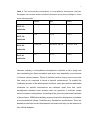
Table 2 The recommended combinations of cross-platform development toolchain.
Developers can exclude edition-unmatched problems among three packages in terms
of the following tables.
GCC-3.3
binutils
gcc
newlib
2.14
3.3.3
1.12.0
2.15
3.4.3
1.12.0
2.15/2.16
4.0.0/4.0.1/4.0.2
1.13.0/1.14.0
2.17
4.1.1
1.14.0
toolchain
GCC-3.4
toolchain
GCC-4.0
toolchain
GCC-4.1
toolchain
However, building a cross-platform development toolchain is still a tough and
time-consuming job. Many exceptions and errors may frequently occur because
of dozens various reasons. Plenty of patches need to be put and source code
files need to be corrected in terms of specific architectures. To simplify the
installation process of the development toolchain, some pre-compiled and tested
toolchains for specific architectures are released. Apart from that, some
development toolchain build systems that can generate a toolchain simply
without complex configurations. According to the previously described hardware
of photo frame, ARM-based building systems that build development toolchains
are enumerated as follows: CodeSourcery, Scratchbox, and Buildroot. There are
detailed procedures to build development toolchains and they can be obtained in
their official websites.
10
3.2 Bootloader
Bootloader is a small program which is called and run before an operating
system is booted and taken over the computers. Its responsibility is to initialize
the hardware devices and establish the memory mapping table. It deploys
appropriate system environment for hardware and software and makes ultimate
preparation for calling the operating system. Bootloader on embedded systems
relies on specific processor architecture and board-level device configuration. As
a result, a Bootloader that is based on the ARM architecture platform is run by no
means on the non-ARM architecture platform. The most widely used bootloaders
are described as follows:
U-boot
U-boot is a multi-platform and multi-architecture, universal bootloader. It
provides multiple flexible features including Network (TFTP, BOOTTP, DHCP,
NFS), Serial, Flash, Mass Storage Devices and multi-file system support. More
details are shown in its official website at http://www.denx.de/wiki/U-Boot.
Blob (Boot Loader Object)
LART comes with its own bootloader, blob (Boot Loader OBject). Blob is
copyrighted by Jan-Derk Bakker and Erik Mouw, and released with a slightly
modified GNU GPL license. It is slightly modified because we do not consider
the operating systems that blob boots as a derived work [11]. More introductions
are listed in its official website at http://www.lartmaker.nl/lartware/blob/.
ARMBoot
ARMboot is an Open-Source firmware suite for ARM-based platforms. ARMboot
is heavily based on the sister project PPCboot, which provides similar
11
functionality on PowerPC-based systems. ARMboot is a common, easy-to-use
and easy-to-port boot platform [12]. More details are presented in its official
website at http://armboot.sourceforge.net/.
3.3 Busybox
BusyBox combines tiny versions of many common UNIX utilities into a single
small executable. It provides replacements for most of the utilities usually found
in GNU fileutils, shellutils, etc. The utilities in BusyBox generally have fewer
options than their full-featured GNU cousins; however, the options that are
included provide the expected functionality and behave very much like their
GNU counterparts. BusyBox provides a fairly complete environment for any
small or embedded system. [13]
By means of unnecessary options unselected, the file system is able to be kept
at a minimal size. In consequence, Busybox implements selected binary
command and related library files for its ultimate file system.
3.4 Tslib
Tslib is kind of middleware program for touchscreen devices. It supplies common
user interface for up-layer programs and communicates with the touchscreen
driver. In tslib, the touchscreen can be developed or manipulated efficiently. In
addition, it improves touchscreen display by smoothing the jitter and
implementing the calibration on touchscreen edges.
3.5 Qt
Qt is a cross-platform application and UI framework. Using Qt, one can write
web-enabled applications once and deploy them across desktop, mobile and
embedded operating systems without rewriting the source code [14]. The current
12
location is http://qt.nokia.com/products which presents all the relevant functions.
3.6 Qt Embedded
Qt embedded is a super set of Qt with complete GUI classes, operating system
encapsulation classes, data structure classes, application and integration
classes. Besides those features, Qt embedded includes a variety of auxiliary
tools on program development, testing, and debugging. In comparison with Qt,
Qt embedded optimizes components for embedded systems and enables the
the application to run solidly and efficiently.
13
4. Developing Flow
4.1 Host machine environment
The author selected Ubuntu is as the developing host machine for current
project because it mainly integrates necessary development tools and facililates
third-party building easily. For this project, Ubuntu 9.10 desktop is the installation
version.
Firstly, a new user armsir is added for this project. The command is as follows:
$ sudo adduser armsir.
Then, the script program adduser can add user armsir, add group armsir, add
user armsir into group armsir, create main directory /home/armsir, copy a few
files from directory /etc/skel, request password, request personal information,
request the confirmation about above questions.
Lastly, the new user armsir is granted root permission. In Ubuntu,the file group in
directory of /etc should be modified. Specifically, the keyword armsir should be
appended in the entry of admin. For instance, admin:x:121:root,armsir.
4.2 Cross-platform Toolchain building
In embedded system development, there are three efficient different ways to
build cross-platform toolchains. They are scratchbox, buildroot, and CLFS. But,
they are still rejected because the above ways need some certain hard disk
space to build the development toolchain. Taking into account the hard disk
space of the low-end host machine, the above three ways have to be put aside.
Apparently, there is no need to present their specific operating instructions in
here.
14
In this project, CodeSourcery and precompiled development toolchain 3.4.1 from
the development board are chosen as the final development toolchains. They
can build a high version (V4.0 or above) development toolchain and act as a low
version (below V4.0) development toolchain separately. Technically, only one
development tool can meet the demand of project development. The reason why
two different development toolchains are selected is to let the high version
toolchain compile high version of Linux kernel (2.6) and to let low version
toolchain charge the rest of compiling tasks. The two following paragraphs
instruct how to install CodeSourcery and the precompiled development toolchain,
respectively.
Installiing CodeSourcery
Now, the latest version of Sourcery G++ Lite Edition for ARM (2009q3-68)
should be downloaded. There are four target OS types, illustrating EABI, uClinux,
GNU/linux and SymbianOS. Here, EABI is selected. Then, the IA32 GNU/Linux
Installer should be downloaded. That is in bin file format and thus JRE has to be
prepared well. Lastly, the graphic installer leads users to accomplish the
procedure. The installation directory is set as "/home/armsir/CodeSourcery".
Installing precompiled development toolchain 3.4.1
Precompiled development toolchain is much easier to handle. Firstly,
arm-linux-gcc-3.4.1.tar.bz2 is copied to the directory "/home/armsir". Then, the
archive
file
is
unpacked
using
the
following
command:"$
tar
-xjvf
arm-linux-gcc-3.4.1.tar.bz2". Lastly, the directory tree is shown with the following
command "$ tree usr >> tmp"; view the result can be seen with the following
command "$ more tmp".
Last but not least,, the two development toolchains' installation path need to be
15
added to environment variable file "/home/armsir/.bashrc". In the end of the file,
we should append the entry "export
PATH=/home/armsir/CodeSourcery/Sourcery_G++_Lite/bin:/home/armsir/usr/lo
cal/arm/3.4.1/bin:$PATH". Afterwards, we can carry out the file .bashrc by the
command "$ source /home/armsir/.bashrc" in order to to synchronize
environment variables.
4.3 Embedded Linux Kernel building
The project does not resort to the latest version of Linux Kernel in place of Linux
2.6.22.19. Note that the latest version of software development in embeddd
system development is sometimes not recommended on account that unstable
versions have bugs that may lead to compilation failure.
We start by downloading Linux Kernel 2.6.22.19 from its official website
"http://www.kernel.org/" to the directory "/home/armsir". Next, we unpack the file.
Then, there is a new directory linux-2.6.22.19 appearing under the directory
"/home/armsir". Lastly, the steps below should be followed strictly.
$ tar xzvf linux2.6.22.19.tar.gz
$ cd linux2.6.22.19
$ vi Makefile
The entry ARCH and CROSS_COMPILE should be modified as follows:
#ARCH
?= $(SUBARCH)
#CROSS_COMPILE
ARCH
?=
= arm
CROSS_COMPILE = /home/armsir/CodeSourcery/Sourcery_G++_Lite/bin
16
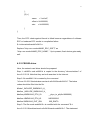
4.3.1 Nand Flash driver
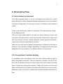
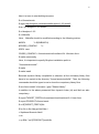
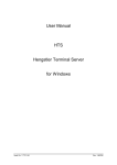
Firstly, the Nand Flash partition should be changed according to the table below.
Figure 4.1 Flash partition tables. There are four partitions for bootloader(0-0x30000),
Linux
kernel(0x30000-1d0000),
file
system(0x200000-0x1e00000),
backup
file
system(0x2000000-0x2000000).
$ vi arch/arm/plat-s3c24xx/common-smdk.c
Here, the partition should be set according to the above table by modifying data
structure smdk_default_nand_part[].
static struct mtd_partition smdk_default_nand_part[] = {
[0] = {
.name
.size
= "boot",
= 0x30000,
.offset = 0,
},
[1] = {
.name
= "kernel",
.offset = 0x30000,
.size
= 0x1d0000,
},
[2] = {
.name
= "jffs2",
.offset = 0x200000,
.size
= 0x1e00000,
17
},
[3] = {
.name
= "ext-fs3",
.offset = 0x2000000,
.size
= 0x2000000,
}
};
Then, the ECC check against Kernel is failed because regardeless of software
ECC or hardware ECC results to compilation failure.
$ vi drivers/mtd/nand/s3c2410.c
Replace "chip->ecc.mode=NAND_ECC_SOFT;" as
"chip->ecc.mode=NAND_ECC_NONE; ”. Up to present, flash device gets ready
well.
4.3.2 CS8900 driver
Here, the network card driver should be prepared.
Step 1: cs8900.c and cs8900.h is copied to the directory "drivers/net/arm" of
linux-2.6.22.19. Note that they are both searched in the Internet.
Step 2: file smdk2410.h is created by the command
"vi linux-2.6.22.19/include/asm-arm/arch-s3c2410/smdk2410.h". The below
codes should be filled into the file.
#ifndef _INCLUDE_SMDK2410_H_
#define _INCLUDE_SMDK2410_H_
#define pSMDK2410_ETH_IO
__phys_to_pfn(0x19000000)
#define vSMDK2410_ETH_IO
0xE0000000
#define SMDK2410_EHT_IRQ
IRQ_EINT9
Step 3: The file mach-smdk2410.c is modified with the command "$ vi
linux-2.6.22.19/arch/arm/mach-s3c2410/mach-smdk2410.c". The statement
18
"#include "asm/arch/smdk2410.h" is added in the beginning and IO mapping in
structure array "map_desc smdk2410_iodesc[]" like the following.
static struct map_desc smdk2410_iodesc[] __initdata = {
/* nothing here yet */
{ vSMDK2410_ETH_IO , pSMDK2410_ETH_IO, SZ_1M, MT_DEVICE },
};
Step 4: An IRQ variable should be defined in the file "include/asm-arm/irq.h".
#define IRQ_TYPE_EDGE_FISING
(1 << 1)
Step 5: The file "drivers/net/arm/Kconfig" should be modified so that the
compiling option of CS8900 is added with the coming commands:
$ vi linux-2.6.22.19/drivers/net/arm/Kconfig
Then, the codes should be appended in the following:
Config ARM_CS8900
tristate "CS8900 support"
depends on NET_ETHERNET && ARM && ARCH_SMDK2410
help
Support for CS8900A chipset based Ethernet cards.
Step 6:
the statement "obj-$(CONFIG_ARM_CS8900)
+= cs8900.o"
should be appended in the file "drivers/net/arm/Makefile".
4.3.3 LCD driver
Then,
we
move
on
to
the
LCD
device
driver.
Mainly,
"arch/arm/mach-s3c2410/mach-smdk2410.c" should be modified.
Step 1: "#include <asm/arch/fb.h>" is added to the above file.
the
file
19
Step 2: init LCD controller parameters:
static struct s3c2410fb_mach_info S3C2410_lcd_cfg __initdata = {
.type
=
.regs
S3C2410_LCDCON1_TFT,
={
.lcdcon1
= S3C2410_LCDCON1_TFT16BPP |
S3C2410_LCDCON1_TFT |
S3C2410_LCDCON1_CLKVAL(0x04),
.lcdcon2
= S3C2410_LCDCON2_VBPD(5) |
S3C2410_LCDCON2_LINEVAL(239) |
S3C2410_LCDCON2_VFPD(4) |
S3C2410_LCDCON2_VSPW(3),
.lcdcon3
= S3C2410_LCDCON3_HBPD(13) |
S3C2410_LCDCON3_HOZVAL(319) |
S3C2410_LCDCON3_HFPD(20),
.lcdcon4
= S3C2410_LCDCON4_MVAL(13) |
S3C2410_LCDCON4_HSPW(18),
.lcdcon5
= S3C2410_LCDCON5_FRM565 |
S3C2410_LCDCON5_INVVLINE |
S3C2410_LCDCON5_INVVFRAME |
S3C2410_LCDCON5_PWREN |
S3C2410_LCDCON5_INVVCLK |
S3C2410_LCDCON5_HWSWP,
},
.width
= 320,
.height
= 240,
.xres
={
.min
= 320,
.max
= 320,
.defval = 320,
20
},
.yres
={
.min
= 240,
.max
= 240,
.defval = 240,
},
.bpp
={
.min
= 16,
.max
= 16,
.defval = 16,
},
.gpcup= 0xffffffff,
.gpcup_mask= 0xffffffff,
.gpccon= 0xaa9556a9,
.gpccon_mask= 0xffffffff,
.gpdup= 0xffffffff,
.gpdup_mask= 0xffffffff,
.gpdcon= 0xaaaaaaaa,
.gpdcon_mask= 0xffffffff,
.lpcsel= 0x00,
};
Step 3: The register parameters of the LCD controller are set:
static void __init smdk2410_init(void)
{
s3c24xx_fb_set_platdata(&qt2410_biglcd_cfg);
platform_add_devices(smdk2410_devices, ARRAY_SIZE(smdk2410_devices));
smdk_machine_init();
21
}
Step 5: The LCD initial function is added to the file "driver/video/s3c2410fb.c".
However, the related codes occupy a rather huge space and thus they are
pasted in Appendix B.
4.3.4 Touchscreen driver
Now, it is time to incorporate the touchscreen device driver into the kernel.
Step 1: s3c2410_ts.c is copied to the directory "drivers/input/touchscreen".
Step 2: the following codes are added:
#include <asm/arch/ts.h>
/* Touchscreen */
struct platform_device s3c_device_ts = {
.name
= "s3c2410-ts",
.id
= -1,
};
EXPORT_SYMBOL(s3c_device_ts);
static struct s3c2410_ts_mach_info s3c2410ts_info;
void __init set_s3c2410ts_info(struct s3c2410_ts_mach_info
*hard_s3c2410ts_info)
{
memcpy(&s3c2410ts_info,hard_s3c2410ts_info,sizeof(struct
s3c2410_ts_mach_info));
s3c_device_ts.dev.platform_data = &s3c2410ts_info;
}
EXPORT_SYMBOL(set_s3c2410ts_info);
Step
3:
The
below
declaration
statement
is
added
to
the
file
22
"include/asm-arm/plat-s3c24xx/devs.h":
extern struct platform_device s3c_device_ts;
Step 4: the file "arch/arm/mach-s3c2410/mach-smdk2410.c" is modified
#include <asm/arch/ts.h>
/*Config for TouchScreen*/
static struct s3c2410_ts_mach_info MY2410_ts_cfg __initdata = {
.delay = 10000,
.presc = 49,
.oversampling_shift = 2,
};
"&s3c_device_ts"
is registered in the structure of "static struct platform_device
*smdk2410_devices[] __initdata" and "set_s3c2410ts_info(&MY2410_ts_cfg);" is
added in the function "static void __init smdk2410_init(void)".
4.3.5 USB driver
Primarily, the file "arch/arm/mach-s3c2410/mach-smdk2410.c" is modified.
Step 1: The USB header file is added:
#include <asm/arch/usb-control.h>
#include <asm/arch/regs-clock.h>
#include <linux/device.h>
#include <linux/delay.h>
//-------------------------------------------------usb
struct s3c2410_hcd_info usb_gec2410_info = {
.port[0] = {
.flags = S3C_HCDFLG_USED
}
};
int usb_gec2410_init(void)/* USB */
{
23
unsigned long upllvalue = (0x78<<12)|(0x02<<4)|(0x03);
printk("USB Control, (c) 2009 s3c2410\n");
s3c_device_usb.dev.platform_data = &usb_s3c2410_info;
while(upllvalue!=__raw_readl(S3C2410_UPLLCON))
{ __raw_writel(upllvalue,S3C2410_UPLLCON);
mdelay(1);
}
return 0;
}
Step 2: usb_ljd2410_init() to function smdk2410_map_io is added for initializing:
static void __init smdk2410_map_io(void)
{
s3c24xx_init_io(smdk2410_iodesc, ARRAY_SIZE(smdk2410_iodesc));
s3c24xx_init_clocks(0);
s3c24xx_init_uarts(smdk2410_uartcfgs, ARRAY_SIZE(smdk2410_uartcfgs));
usb_gec2410_init();
}
4.3.6 Kernel configuration
Next, the kernel is configured. For a simple kernel configuration, the s3c2410
configuration file is copied as the configuring template.
$ cp arch/arm/configs/s3c2410_defconfig .config
$ make menuconfig
In accordance with the actual project demand, the Kernel options should be
customised. Here, the author mainly adjusted processor types, network modules,
file system, and device drivers. The final Kernel configuration can support
processor s3c2410, partial network functions, Memory Technology Device
(MTD), USB device, LCD device, touchscreen device, JFFS2, CRAMFS, NFS
24
and remove the unnecessary functions like the rest of processors support, Ext3
file system support, IPV6, Bluetooth device and so forth.
Note that Boot options are set as "root=/dev/nfs
nfsroot=192.168.11.2:/home/armsir/rootfs
ip=192.168.11.100:192.168.11.1:255.255.255.0 init=/linuxrc
console=ttySAC0,115200" in the development instead of "root=/dev/mtdblock2
rootfstype=jffs2 console=ttySAC0,115200 init=/linuxrc mem=64M" in the real
product.
Finally, the zimage file is produced with the command "$ make zImage". In this
case, it is located in the directory "/home/armsir/linux-2.6.22.19/arch/arm/boot".
4.4 Embedded Linux file system building
First of all, a root directory for root file system named rootfs should be created:
$ mkdir /home/armsir/rootfs
Then, referring to Linux Filesystem Hierarchy Standard (LHS), the various level
directories are completed with the following commands:
$ cd rootfs
$ mkdir bin dev etc lib proc sbin sys usr
$ mkdir usr/bin usr/lib usr/sbin lib/modules
$ sudo mknod -m 600 dev/console c 5 1
$ sudo mknod -m 666 dev/null c 1 3
$ mkdir mnt tmp var
$ chmod 1777 tmp
$ mkdir mnt/etc mnt/jffs2 mnt/yaffs mnt/data mnt/temp
$ mkdir var/lib var/lock var/log var/run var/tmp
$ chmod 1777 var/tmp
$ mkdir home root boot
25
Next,it is tome to start building busybox.
$ cd /home/armsir
$ wget http://busybox.net/downloads/busybox-1.9.2.tar.bz2
$ tar -xjvf busybox-1.9.2.tar.bz2
$ cd busybox-1.9.2
$ vi Makefile
Here,
Makefile should be modified according to the following entries:
#ARCH
?= $(SUBARCH)
#CROSS_COMPILE
?=
ARCH =arm
CROSS_COMPILE = /home/armsir/usr/local/arm/3.4.1/bin/arm-linux$ make menuconfig
Here, it is important to specify Busybox installation prefix to
"/home/armsir/rootfs".
$ make
$ make install
Because dynamic library compilation is selected, all the necessary library files
have to be copied to the directory "/home/armsir/rootfs/lib". Then, the following
commands should be typed so as to show the compulsory library files:
$ arm-linux-readelf -d busybox | grep "Shared library"
In addition to the above presented files, dynamic linker (ld) and libdl are also
compulsory.
$ export TARGET_PREFIX=/home/armsir/usr/local/arm/3.4.1/arm-linux
$ export PRJROOT=/home/armsir
$ cd ${TARGET_PREFIX}/lib
$ for file in libc libcrypt libdl libm \
> libpthread libresolv libutil
> do
> cp $file-*.so ${PRJROOT}/rootfs/lib
26
> cp -d $file.so.[*0-9] ${PRJROOT}/rootfs/lib
> done
$ cp -d ld*.so* ${PRJROOT}/rootfs/lib
After
that,
configuration
example
files
are
copied
to
the
directory
"/home/armsir/rootfs/etc":
$ cd /home/armsir/busybox-1.9.2
$ cp -a examples/bootfloppy/etc/* ${PRJROOT}/roofs/etc
Then the new copied files fstab, inittab, profile and directory init.d are modified.
Firstly, global variables for development board should be loaded.
$ cd /home/armsir/rootfs/etc
$ vi profile
LD_LIBRARY_PATH=/lib:/usr/lib:/usr/tslib/lib
export LD_LIBRARY_PATH
Secondly, the inittab file should be modified.
$ vi inittab
::sysinit:/etc/init.d/rcS
::respawn:-/bin/login
::restart:/sbin/init
::ctrlaltdel:/sbin/reboot
::shutdown:/bin/umount -a -r
::shutdown:/sbin/swapoff -a
Thirdly, fstab should be modified.
proc
/proc
proc
defaults
0
0
27
none
/tmp
ramfs
defaults
0
0
mdev
/dev
ramfs
defaults
0
0
sysfs
/sys
sysfs
defaults
0
0
Fourthly, the file "init.d/rcS" should be modified.
$ vi init.d/rcS
#! /bin/sh
echo "----------mount all"
/bin/mount -a
echo "----------Starting mdev......"
/bin/echo /sbin/mdev > /proc/sys/kernel/hotplug
mdev -s
Lastly,
the file mdev.conf is created.
$ touch mdev.conf
4.5 Configuring the TFTP server in the host machine
$ sudo apt-get install tftp-hpa tftpd-hpa
$ sudo apt-get install xinetd
$ sudo apt-get install netkit-inetd
$ sudo chmod 777 /tftpboot
$ sudo vi /etc/xinetd.d/tftp
service tftp
{
socket_type = dgram
protocol = udp
wait = yes
28
user = root
server = /usr/sbin/in.tftpd
server_args = -s /tftpboot
disable = no
per_source = 11
cps = 100 2
flags = IPv4
}
Finally, zImage is copied to the directory tftpboot.
4.6 Configuring the NFS server in the host machine
$ sudo apt-get install install nfs-kernel-server
$ sudo apt-get install nfs-common
$ sudo vi /etc/exports
/home/armsir/rootfs 192.168.11.100(rw,sync,no_root_squash)
$ sudo
exportfs
-r
$ sudo /etc/init.d/portmap start
$ sudo /etc/init.d/nfs-kernel-server start
4.7 Bootloader Porting
In this project, there are two different bootloaders. One is precompiled U-boot for
gec2410 and the other one is gec2410-bios from the development board
company. The former one is used for NFS boot under development while the
latter one is to load the JFFS2 boot in the final product. They are both image files
and, hence, they can be uploaded to development board directly. For
gec241-bios, there is no need to make any changes; for U-boot, a slight setting
needs be implemented as described in the next Section.
29
4.8 Kernel startup testing and root file system mounting by NFS
Firstly of all, minicom should be installed and configured.
$ sudo apt-get install minicom
$ sudo minicom -s
A: Serial Device: /dev/ttyS0
E: Bps/Par/Bits: 115200 8N1
F: Hardware Flow Control: No
G: Software Flow Control: No
Then , we should select "Save setup as df1" and exit and restart.
$ sudo minicom
Secondly, the u-boot environment variables should be set after the development
board is booted.
#setenv serverip 192.168.11.2
#setenv ipaddr 192.168.11.100
#setenv gatewayip 192.168.11.1
#setenv netmask 255.255.255.0
#setenv ethaddr 01:23:45:67:89:AB
#setenv bootargs root=/dev/nfs nfsroot=192.168.11.2:/home/armsir/rootfs
ip=192.168.11.100:192.168.11.1:255.255.255.0 init=/linuxrc
console=ttySAC0,115200
#saveenv
Thirdly, Linux Kernel should be downloaded to memory by TFTP.
#tftp 30008000 zImage
#go 30008000
Note that sometimes outputs unrecognized/unsupported the machine ID. The
solution is presented below.
The file /home/armsir/linux-2.6.22.19/arch/arm/kernel/head.S should be
30
modified.
_INIT
.type stext, %function
ENTRY(stext)
/****************add here*****************/
mov r0, #0
mov r1, #0xc1
ldr r2, =0x30000100
/***************end add******************/
msr cpsr_c, #PSR_F_BIT | PSR_I_BIT | MODE_SVC
Fourthly, we should restart development board and repeat the third step.
Finally, shell appears if there is no problem.
4.9 Tslib building
Firstly, CVS should be installed because tslib will be downloaded in this way.
$ sudo apt-get install cvs
Secondly, the latest version of Tslib should be downloaded.
$export CVSROOT=:pserver:[email protected]:/cvs
$cvs login
Logging in to: pserver:[email protected]:2401/cvs
CVS password:
anoncvs
cvs login: CVS password file /home/tekkaman/.cvspass does
not exist - creating a new file
$cvs co apps/tslib
Thirdly, Tslib should be compiled.
$ cd /home/armsir/apps/tslib
After referring to the INSTALL document, autoconf, automake, libtool need to be
31
complusory.
$ sudo apt-get install apt-get install autoconf automake libtool
$ export CC=arm-linux-gcc
$ export CXX=arm-linux-g++
$ ./autogen.sh
$ echo "ac_cv_func_malloc_0_nonnull=yes" >$ARCH_tslib.cache
$ /configure --prefix=home/armsir/rootfs/usr/tslib
--host=arm-linux --cache-file=$ARCH_tslib.cache
--enable-input=no
$ make $ make install
$ vi /home/armsir/rootfs/etc/profile
export TSLIB_ROOT=/usr/tslib
export TSLIB_TSEVENTTYPE=event0
export TSLIB_TSDEVICE=/dev/event0
export TSLIB_CALIBFILE=/etc/pointercal
export TSLIB_CONFFILE=$TSLIB_ROOT/etc/ts.conf
export TSLIB_PLUGINDIR=$TSLIB_ROOT/lib/ts
export TSLIB_CONSOLEDEVICE=none
export TSLIB_FBDEVICE=/dev/fb0
export PATH=$TSLIB_ROOT/bin:$PATH
export LD_LIBRARY_PATH=$LD_LIBRARY_PATH:$TSLIB_ROOT/lib
$ vi /home/armsir/rootfs/usr/tslib/etc/ts.conf
module_raw input
module pthres pmin=1
module variance delta=30
module dejitter delta=100
module linear
32
4.10 Qt Embedded building
Step 1: We should download Qt Embedded and enter the unpacked directory.
$ tar -zxvf qt-embedded-linux-opensource-src-4.5.1.tar.gz
$ cd qt-embedded-linux-opensource-src-4.5.1
Step 2: Unnecessary library files can be dropped by referring to the Help
document.
$ ./configure -prefix /home/armsir/qt-port -opensource -fast -no-largefile -no-stl
-exceptions
-qt-sql-sqlite
-no-phonon-backend
-no-qt3support
-no-svg
-no-xmlpatterns
-no-webkit
-no-phonon
-no-scripttools
-I
"/home/armsir/rootfs/usr/tslib/include" -L "/home/armsir/rootfs/usr/tslib/lib" -qt-zlib
-qt-libtiff -qt-libpng -qt-libmng -qt-libjpeg -no-openssl
-make libs -make tools
-make-translations -nomake examples -nomake docs -nomake demos -no-nis
-no-cups -no-iconv -no-pch -no-dbus -xplatform qws/linux-arm-g++ -embedded
arm -little-endian -depth 16,32
$ make
$ make install
Step 3: Qt files should be ported into root file system of development board.
$ install /home/armsir/rootfs/usr/qt
$ cp /home/armsir/qt-port/lib /home/armsir/rootfs/usr/qt
$ cp /home/armsir/qt-port/mkspecs /home/armsir/rootfs/usr/qt
$ cp /home/armsir/qt-port/plugins /home/armsir/rootfs/usr/qt
$ cp /home/armsir/qt-port/translations /home/armsir/rootfs/usr/qt
Step 4: Qt Embedded environment variables should be set.
$ vi /home/armsir/rootfs/etc/profile
export QTDIR=/usr/qt
export
33
LD_LIBRARY_PATH=$QTDIR/lib:$QTDIR/plugins/imageformats:$LD_LIBRARY
_PATH
export QT_PLUGIN_PATH=$QTDIR/plugins
export QWS_MOUSE_PROTO="tslib:/dev/event0"
export QT_QWS_FONTDIR=/usr/qt/lib/fonts
export QWS_DISPLAY="LinuxFb:/dev/fb0:mmWidth=320:mmHeight=240"
export QWS_SIZE="320x240"
Step 5: The setting should be added so that the touchscreen calibration program
can be activated as embedded Linux starts.
$ vi /home/armsir/rootfs/etc/profile
The statement "/usr/tslib/bin/ts_calibrate" should be appendedin the end.
4.11 Photo frame application development and porting
In this project, the main application is developed by Qt Creator on the Windows
platform. Qt Creator is a cross-platform Qt IDE. It integrates with the Qt libraries
and development tools as a complete SDK. Although the application is
developed on the Windows platform, its source codes can still be compiled
successfully in the Linux platform.
The main application is primarily to display pictures. It includes common
components to view pictures, such as open, backward, forward, zoom-in,
zoom-out, full screen, delete, slide show, anticlockwise rotation, clockwise
rotation. Partial codes are presented in Appendix C.
Now, the source codes should be copied into home directory of Linux platform
from the PhotoFrame directory of the Windows platform.
$ cd /home/armsir/PhotoFrame
$ qmake -project
34
$ qmake
$ make
$ cp PhotoFrame /home/armsir/rootfs/usr/bin
Lastly, some settings should be added in order to change the PhotoFrame boot
into embedded Linux boot.
$ vi /home/armsir/rootfs/etc/profile
The statement "/usr/bin/PhotoFrame -qws" should be appended in the end.
4.12 Reprogramming gec2410-bios into the Flash device
During the development phase, U-boot is used as bootloader. But now,
gec2410-bios is used as bootloader for the final product because the author’s
U-boot fails to store the Kernel image and the file system image into the Flash
device. The procedure is as follows:
Step 1: We should connect the development with the computer using a JTAG
board.
Step 2: We should install giveio driver on the host machine.
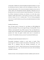
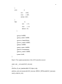
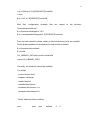
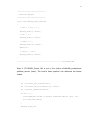
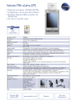
Step 3: We should execute the batch file SJF2410_BIOS.BAT
Then, the information is displayed as follows:
35
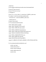
Figure 4.2 SJF2410_BOIS.BAT operational process. It is requested to choose which
function is to be tested.
Here, we should select 0 to test the flash device.
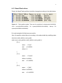
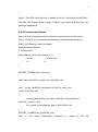
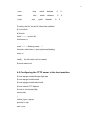
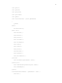
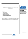
Next, follow the below operations.
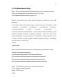
Figure 4.3 SJF2410_BOIS.BAT operational process. It is requested to choose how
many target blocks need to be programmed.
Then, we can start to program the Flash device.
Finally, gec2410-bios is recovered from U-boot.
4.13 Embedded Linux kernel porting
In this step, the author changes to Windows environment using another terminal
program named DNW. And then, he starts the development board and
configuring terminal parameters. The following information appears.
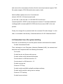
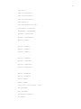
36
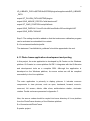
Figure 4.4 Terminal startup information. There are seven options bootloader provides to
make human-computer interaction.
Now, we should select 0 and download the zImage that is built on Linux platform.
Then, we should select 2 to write the zImage into Nand Flash.
At last, we should restart the development board and select 7 so as to startup
Linux automatically.
4.14 Building the root file system image and porting
Step 1: We should download and install mkfs.jffs2
$ sudo apt-get install mtd-utils
$ sudo mkfs.jffs2 -r /home/armsir/rootfs -o rootfs.jffs2 -p -l -n -e 0x4000 -m size
Step 2: We should repeat the steps in Section 4.13 to program rootfs.jffs2 into
the Flash device
37
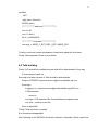
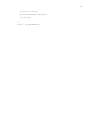
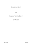
4.15 Testing and debugging the whole product
When switching on the power of hardware, Linux starts as a classical Penguin
logo emerges. Then, the Tslib calibrating program is called. Users can adjust the
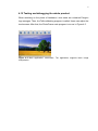
touchscreen. After that, the PhotoFrame main program is run as in Figure 4.5.
Figure 4.5 Main application' screenshot. The application supports basic image
manipulation.
38
5. Summary
The project implements a set of comprehensive solutions to electronic photo
frame devices. Manufactures or researchers can continue to enhance other
features or upgrade related hardware on the basis of this project. And then, they
can develop an enhanced edition of the photo frame device or other functional
electronic devices, like PDA, Set-Top-Box with picture view.
Although the project is developed on the GEC2410 hardware platform, the
developing approach can still serve other ARM architecture hardware platforms,
as well. Developers can only pay attention to distinguish different hardware
drivers among other development boards when compiling the Linux kernel.
Lastly, there is an unsolved segmentation problem when carrying out a picture
slide show on the development board. But it works well on the host machine
platform. Apart from that, there are dozens of errors that occurred during the
development of the Linux distribution. These problems may be caused due to
incomplete software environment on host machine, incompatible software
editions, data structure changes or header file missing in Linux source codes.
They are not yet spread out in this project because they are not hard to handle
relying on error logs. If they were mentioned, they would occupy plenty of pages
that are not in the scope of this thesis. For such errors, the usual solutions are to
patch host machines or related software in according with specific errors.
39
References
[1]
Karim Yaghmour, 2003, Building Embedded Linux Systems. United
States of America: O'Reilly & Associates, Inc., p. 58.
[2]
[www-document].
Available at: http://www.arm.com/products/processors/index.php/
Referred: 01.03.2010
[3]
S3C2410A – 200MHz & 266MHz 32-Bit RISC Microprocessor
User's Manual, Revision 1.0 (March 2004), Samsung Electronics Co.,
Ltd. San #24 Nongseo-Ri, Giheung- Eup Yongin-City, Gyeonggi-Do,
Korea C.P.O. Box #37, Suwon 449-900
[4]
Karim Yaghmour, 2003, Building Embedded Linux System. United
States of America: O'Reilly & Associates, Inc., p. 60
[5]
John L. Hennessy, David A.Patterson, 2003, Computer Architecture A
Quantitative Approach: 340 Pine Street, Sixth Floor, San Francisco, CA
94104-3205, USA: Morgan Kaufmann, p. 130
[6]
[www-document]. Available at: http://www.gd-emb.org/en/en2410.php/
Referred: 01.03.2010
[7]
LTV350QV-F0E Product Information, Samsung Electronics Co., Ltd.
San #24 Nongseo-Ri, Giheung- EupYongin-City, Gyeonggi-Do, Korea
C.P.O. Box #37, Suwon 449-900
40
[8]
[www-document]. Available at: http://gcc.gnu.org/
Referred: 01.03.2010
[9]
[www-document]. Available at: http://sourceware.org/newlib/
Referred: 01.03.2010
[10]
[www-document]. Available at: http://www.lartmaker.nl/lartware/blob/
Referred: 01.03.2010
[11]
[www-document]. Available at: http://armboot.sourceforge.net/
Referred: 01.03.2010
[12]
[www-document]. Available at: http://busybox.net/about.html/
Referred: 01.03.2010
[13]
[www-document]. Available at: http://qt.nokia.com/products/
Referred: 01.03.2010
[14]
Karim Yaghmour, 2003, Building Embedded Linux System. United
States of America: O'Reilly & Associates, Inc., p. 178
41
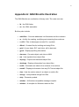
Appendix A: GNU Binutils Illustration
The GNU Binutils are a collection of binary tools. The main ones are:
ld - the GNU linker.
as - the GNU assembler.
But they also include:
addr2line - Converts addresses into filenames and line numbers.
ar - A utility for creating, modifying and extracting from archives.
c++filt - Filter to demangle encoded C++ symbols.
dlltool - Creates files for building and using DLLs.
gold - A new, faster, ELF only linker, still in beta test.
gprof - Displays profiling information.
nlmconv - Converts object code into an NLM.
nm - Lists symbols from object files.
objcopy - Copies and translates object files.
objdump - Displays information from object files.
ranlib - Generates an index to the contents of an archive.
readelf - Displays information from any ELF format object file.
size - Lists the section sizes of an object or archive file.
strings - Lists printable strings from files.
strip - Discards symbols.
windmc - A Windows compatible message compiler.
windres - A compiler for Windows resource files.
42
Appendix B: LCD initial functions
The following codes are specific to LTV350QV_FOE device.
Step 1: Define LTV350QV_FOE necessary data structure and type.
typedef struct _LTV350qv_spi_data_{
unsigned char
Device_ID;
//ID of the device
unsigned int
Index;
//index of register
unsigned long Structure;
//structure to be writed
}LTV350QV_SPI_Data;
//macro definition for LTV350QV_POE
//MAKE_HIGH(LTV350QV_CS)
#define CS_H
__raw_writel(__raw_readl(S3C2410_GPCDAT)|(1<<8), S3C2410_GPCDAT)
//MAKE_LOW(LTV350QV_CS)
#define CS_L
__raw_writel(__raw_readl(S3C2410_GPCDAT)&~(1<<8), S3C2410_GPCDAT)
//MAKE_HIGH(LTV350QV_SCL)
#define SCLK_H __raw_writel(__raw_readl(S3C2410_GPCDAT)|(1<<9), S3C2410_GPCDAT)
//MAKE_LOW(LTV350QV_SCL)
#define SCLK_L __raw_writel(__raw_readl(S3C2410_GPCDAT)&~(1<<9), S3C2410_GPCDAT)
//MAKE_HIGH(LTV350QV_SDI)
#define SDI_H __raw_writel(__raw_readl(S3C2410_GPCDAT)|(1<<10), S3C2410_GPCDAT)
//MAKE_LOW(LTV350QV_SDI)
#define SDI_L __raw_writel(__raw_readl(S3C2410_GPCDAT)&~(1<<10), S3C2410_GPCDAT)
//MAKE_HIGH(LTV350QV_RST)
#define RST_H __raw_writel(__raw_readl(S3C2410_GPDDAT)|(1<<0), S3C2410_GPDDAT)
//MAKE_LOW(LTV350QV_RST)
#define RST_L __raw_writel(__raw_readl(S3C2410_GPDDAT)&~(1<<0), S3C2410_GPDDAT)
43
Step 2: Functions implementation
//***************************************************************
//**********these functions for SUMSUN LTV350QV TFT LCD****************
//***************************************************************
//short delay for about 90*time ns
static void LTV350QV_Short_Delay(u_char time)
{
//u_char i;
//for(i=0;i<time*10;i++) ;
//about 180 ns
ndelay(150);
}
static void LTV350QV_Rst(void)
{
RST_L;
mdelay(1);
RST_H;
mdelay(1);
}
static void LTV350QV_Register_Write(LTV350QV_SPI_Data regdata)
{
u_char i,temp1;
u_int temp2;
u_long temp3;
unsigned long flags;
//write index
temp1=regdata.Device_ID<<2 | 0<<1 | 0<<0;
temp2=regdata.Index;
temp3=(temp1<<24) | (temp2<<8);
//register index
44
local_irq_save(flags);
CS_L;
LTV350QV_Short_Delay(1);
for(i=0;i<24;i++)
{
SCLK_L;
if(temp3 & (1<<(31-i)) )
//if is H
SDI_H;
else
SDI_L;
LTV350QV_Short_Delay(1);
//setup time
SCLK_H;
LTV350QV_Short_Delay(1);
//hold time
}
CS_H;
LTV350QV_Short_Delay(5);
//write instruction
temp1=regdata.Device_ID<<2 | 1<<1 | 0<<0;
//instruction
temp2=regdata.Structure;
temp3=(temp1<<24) | (temp2<<8);
CS_L;
LTV350QV_Short_Delay(1);
for(i=0;i<24;i++)
{
SCLK_L;
if(temp3 & (1<<(31-i)) )
SDI_H;
else
SDI_L;
LTV350QV_Short_Delay(1);
//if is H
45
SCLK_H;
LTV350QV_Short_Delay(1);
}
CS_H;
local_irq_restore(flags);
}
/****************************************
* *
****************************************/
static void LTV350QV_Write(u_int index, u_int regdata)
{
LTV350QV_SPI_Data WriteData;
WriteData.Device_ID=LTV350QV_POE; //0x1d
WriteData.Index=index;
//
WriteData.Structure=regdata;
LTV350QV_Register_Write(WriteData);
}
/****************************************
* *power ON sequence
****************************************/
static void LTV350QV_Power_ON(void)
{
//Initialize VD[7:0],LCDVF[2:0],VM,VFRAME,VLINE,VCLK,LEND
__raw_writel(0xaa9556a9,S3C2410_GPCCON);
//LCDVF[0],[1],[2]---output;VD[0],[1],[2]----output.
__raw_writel(0xffffffff, S3C2410_GPCUP); // Disable Pull-up register
//DPRINTK("%s()\n", __FUNCTION__);
LTV350QV_Write(9, 0x0000);
mdelay(150);
LTV350QV_Write(9, 0x4000);
46
LTV350QV_Write(10, 0x2000);
LTV350QV_Write(9, 0x4055);
mdelay(550);
LTV350QV_Write(1, 0x409d);
LTV350QV_Write(2, 0x0204);
LTV350QV_Write(3, 0x0100);
LTV350QV_Write(4, 0x3000);
LTV350QV_Write(5, 0x4003);
LTV350QV_Write(6, 0x000a);
LTV350QV_Write(7, 0x0021);
LTV350QV_Write(8, 0x0c00);
LTV350QV_Write(10, 0x0103);
LTV350QV_Write(11, 0x0301);
LTV350QV_Write(12, 0x1f0f);
LTV350QV_Write(13, 0x1f0f);
LTV350QV_Write(14, 0x0707);
LTV350QV_Write(15, 0x0307);
LTV350QV_Write(16, 0x0707);
LTV350QV_Write(17, 0x0000);
LTV350QV_Write(18, 0x0004);
LTV350QV_Write(19, 0x0000);
mdelay(200);
LTV350QV_Write(9, 0x4a55);
LTV350QV_Write(5, 0x5003);
__raw_writel(0xaaaaaaaa, S3C2410_GPDCON);
__raw_writel(0xffffffff, S3C2410_GPDUP);
__raw_writel(3, S3C2410_LCDINTMSK);
__raw_writel(0, S3C2410_TPAL);
__raw_writel(0, S3C2410_LPCSEL);
}
// MASK LCD Sub Interrupt
// Disable Temp Palette
// Disable LPC3600
47
/**********************************
* *power OFF sequence
**********************************/
static void LTV350QV_Powen_OFF(void)
{
/* GON -> 0, POC -> 0 */
LTV350QV_Write(9, 0x4055);
/* DSC -> 0 */
LTV350QV_Write(5, 0x4003);
/* VCOMG -> 0 */
LTV350QV_Write(10, 0x0000);
mdelay(20);
/* AP[2:0] -> 000 */
LTV350QV_Write(9, 0x4000);
}
//------------------------------------------------------end LTV350-POE
Step 3: LTV350QV_Power_ON is put in the funtion s3c2410fb_probe(struct
platform_device *pdev). The tuck-in exact position can reference the below
codes.
ret = s3c2410fb_init_registers(info);
ret = s3c2410fb_check_var(&fbinfo->var, fbinfo);
ret = register_framebuffer(fbinfo);
if (ret < 0) {
printk(KERN_ERR "Failed to register framebuffer device: %d\n", ret);
goto free_video_memory;
}
LTV350QV_Power_ON();
48
Appendix C: The implementation of slide show
/*slide show initialization*/
void PictureInterface::initSlideStart()
{
if(imageList.size()>1)
/* To hide all bars like full-screen display*/
{
statusBar()->hide();
naviToolBar->hide();
operToolBar->hide();
if(index==0)
;
else
{
index = -1;
}
timer->start();
/* start a timer for interval to display next image*/
}
}
/* implement slide show*/
void PictureInterface::slideShow()
{
if(index==imageList.size()-2)
{
timer->stop();
statusBar()->show();
naviToolBar->show();
operToolBar->show();
/* check if there are more images*/
49
}
else
{
fadeInWidget();
}
}
/* implement a fading process*/
void PictureInterface::fadeInWidget()
{
if(faderWidget)
{
faderWidget->close();
}
faderWidget = new FaderWidget(this);
faderWidget->start();
next();
}
#ifndef PICTUREINTERFACE_H
#define PICTUREINTERFACE_H
#include <QMainWindow>
#include <QDir>
#include <QPointer>
#include <QPoint>
#include <QToolBar>
#include "faderwidget.h"
#include "imagewidget.h"
#define NEXT 1
#define PREV 0
50
class QAction;
class QToolBar;
class QClipboard;
class QScrollArea;
class QTimer;
class PictureInterface : public QMainWindow
{
Q_OBJECT
public:
PictureInterface();
public slots:
void selectDir();
void nextSlot();
void prevSlot();
void rotateLeft();
void rotateRight();
void zoomIn();
void zoomOut();
void present();
void deletePic();
void slideShow();
void initSlideStart();
protected:
void resizeEvent(QResizeEvent *event);
private slots:
void loadPicWithProgressDialog(bool isNext);
void fadeInWidget();
private:
void mouseDoubleClickEvent ( QMouseEvent * event );
void next();
51
void prev();
void createActions();
void createToolBars();
void createStatusBar();
void drawPic();
void setPicNumber(int num);
QScrollArea *scrollArea;
ImageWidget *imageWidget;
QToolBar *naviToolBar;
QToolBar *operToolBar;
QAction *dirAct;
QAction *nextAct;
QAction *prevAct;
QAction *leftAct;
QAction *rightAct;
QAction *zoomInAct;
QAction *zoomOutAct;
QAction *presentAct;
QAction *deletAct;
QAction *slideAct;
QPoint oldPos;
QTimer *timer;
const static int interval = 5000;
int picNumber;
QDir imageDir;
QStringList imageList;
int index;
52
QClipboard *clipboard;
QPointer<FaderWidget> faderWidget;
int isPresent;
};
#endif // PICTUREINTERFACE_H