1
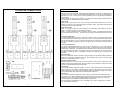
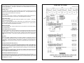
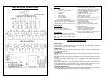
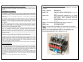
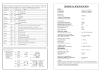
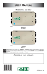
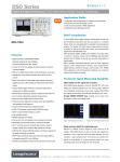
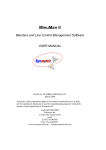
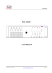
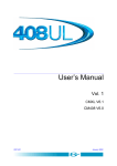
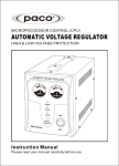
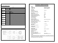
TECHNICAL SPECIFICATION
DIL switch (SW3) settings
Table A
Function Selected
Switch No.1
Position 1
Up
On
“A” internally enabled
Down
Off
“A” internally disabled
Switch No.2
Function Selected
Up
Position 1
On
Down
Off
Switch No.3
Brown
Up
On
Position 1
Down
Off
Red
Position 2
0-10V Signal
0-5V Signal
Function Selected
Analogue input, 0-5Vdc, 0-10Vdc and 4-20 mA and SW1 in the on position
Logic inputs A: Phase Angle, B: Burst Fire, U:
Up, D: Down
Up
On
Limit input 0-5V dc, current limit set by VR2, current trip set by VR1
Down
Off
Limit input off
Orange
Up
On
Inductive load timing
Position 3
Down
Off
Resistive load timing
Yellow
Up
On
Reverse pulse transformer outputs
Position 4
Down
Off
Standard pulse transformer outputs
Green
Up
On
Soft Start/Slew rate ENABLED (1 second factory preset)
Position 5
Down
Off
Soft Start/Slew rate DISABLED
Blue
Up
On
Timing for 12 pulse operation using additional FC36M
Position 6
Down
Off
Standard timing position
Power connections
LINE 1
LINE 1
LINE 2
LINE 2
LINE 3
LINE 3
LINE 3
SUPPLY
FC36MV (400V)
FC36MV (230V)
FC36MV (110V)
360/440V ac @ 50/60 Hz
205/255V ac @ 50/60 Hz
95/125V ac @ 50/60 Hz
ISOLATION
Isolation voltage
3500Vrms
CURRENT CONSUMPTION
Full conduction – TX secondary
500mA
GATE PULSES
Initial short circuit gate current
Sustaining short circuit gate current
Initial pulse voltage (open circuit)
Sustaining pulse voltage (open circuit)
Initial gate pulse rate of rise
Pulse width 50/60 Hz
Pulse train frequency
750mA
400mA
10V
8V
1A/us
22us
25 kHz
OPERATION MODES
Selection by input enable or auto
Burst Fire and Phase Angle
CONTROL SIGNAL ANALOGUE
Voltage signal into 10K ohms / 20K ohms
Current signal into 240 ohms
0 – 5 V dc / 0-10V dc
4 – 20 mA
CONTROL SIGNAL LOGIC
Opto-isolated inputs
5 – 24 V dc
SOFT START
Adjustable range from power up
0 – 30 seconds
CURRENT LIMIT
Controlled limit or over-current trip
0-5V dc
LOAD OPTIONS
Selection by switch (SW3)
Resistive or Inductive
TEMPERATURE LIMITS
Operating range (°C)
Storage (°C)
0 - 65°C
0 to 85°C
MECHANICAL DIMENSIONS
Length (mm) x Width (mm) x Height (mm)
Fixing centres and holes (mm)
203 x 108 x 40
2 by 96.5 x75 (3.5mm Holes)
FUSING
It is recommended that semiconductor fast acting type fuses or circuit breakers (Semiconductors –
MCB) be used for device protection. On initial operation, some loads may need an increased Factor
of Safety (F of S) for unit and/or device protection.
See SRA Data sheet X10255 for further information.
LINE 1
LINE 2
LINE 3
LINE 3
6
7
THYRISTOR CONNECTIONS
LOGIC CONTROL INPUT
The logic control inputs are optically isolated and are ideally utilised for remote control in electrically noisy
environments. The logic inputs A, B, UP and DOWN are activated by a 5 to 24 V dc signal with respect to
terminal C which is 0 V. The logic input can also be activated by the 5V dc output from the FC36MV via
relay switching.
For the following logic control options, position No.1 on the 6 way DIL switch (SW3) should be switched to
the OFF position. For additional control options see table A.
Logic control
Maximum power output levels are set by the input voltage at the terminal marked SIG I/P. With, for
example, 4V on this input, the output will be limited to a maximum of 80%. Link the SIG I/P terminal to the
5V output terminal for 0-100% control range.
Phase Angle control
Option 1 – the switch marked SW1 can be switched to the ON position, which utilises the internal 5V
supply. This ON position simply connects terminals A with 5V.
Option 2 – the switch marked SW1 can be switched to the OFF position. The position isolates the inputs
and disconnects terminals A from 5V. Inputs A and C then require an external supply between 5 and 24V
dc.
To Increase output power
The terminal marked UP requires a 5 to 24 V dc supply. Terminal C is 0V. The output power will increase
at a rate determined by the ramp setting on VR3 (0-30 seconds). The output will reach its maximum when
the ramp time has elapsed. If the UP signal is terminated during the ramp time the output will remain at
that level, for example, if ramp time is 10 seconds. UP signal is on for 5 seconds, power output will ramp
up to 50%.
To decrease output power
The terminal marked DOWN requires a 5 to 24V dc supply. Terminal C is 0V. The output power will
decrease at a rate determined by the ramp setting of VR3. The output will decrease to zero should the
DOWN signal be maintained. If the DOWN signal is interrupted before the ramp down time has elapsed,
the output will stay at that level. Proportional control can be achieved with an on/off signal. This
arrangement is particularly useful for temperature controllers, relay switching and PC based process
controllers.
Burst Fire control
The switch marked SW1 should be switched to the OFF position and the terminal marked B should be
linked to 5V. Link terminals marked 5V and SIG I/P. For remote Burst Firing control, a 5 to 24V dc signal
should be connected between B and C. C is 0V.
Inductive or Resistive loads
With switch position 3 on DIL switch No.3 in the OFF position, the firing circuit is configured to control
resistive and some slightly inductive loads. When the switch is in the ON position, the firing circuit should
be used on inductive (transformer and coil) type loads.
Current Limit
The current limit input is designed to operate from a 0-5V dc input connected between terminals marked
LIMIT input and 0V. The current limit feedback signal is fed into the microprocessor IC3 and compared
with the voltage set by VR2 (I SET). When the feedback voltage is greater than the voltage on pin 5 (IC3),
the controller will start to ramp down until the current reaches the I SET level.
Current Trip
The current trip is designed to operate from a 0-5V dc input connected between terminals marked LIMIT
input and 0V.). The current limit feedback signal is fed into the microprocessor IC3 and compared with the
voltage set by VR3 (I TRIP). When the feedback voltage is greater than the voltage on pin 7 (IC3), the
controller will shut down immediately and will stay latched in this state until
the microprocessor is powered down or reset. The voltage on pin 7 (IC3) is normally set to 4.2V to allow
for a 120% maximum current level.
8
5
Manual Control
The FC36MV firing circuit has a 5Vdc output that can be used to supply the clockwise end of a
5K ohm potentiometer. The wiper is connected to the terminal marked SIG I/P and the
counterclockwise
end to 0V.
67
CONTROL OPTIONS
Voltage control
For control using a remote dc signal the positive input should be connected to the terminal
marked SIG I/P and the negative input to be connected to 0V. The input impedance is 10K
ohms for 0-5V input and 20K ohms for 0-10V input.
Current control
For current control connect a 4-20mA dc signal between terminals marked 4-20mA and 0V.
This input can also be used as 1-5V dc input. The input impedance is 240 ohms.
Phase Angle control
Option 1 - the switch marked SW1 should be switched to the on position. This position
connects terminals A with 5V.
Option 2 – (see Soft Starting) the switch marked SW1 can be switched to the OFF position.
The OFF position isolates the inputs and disconnects terminals A from 5V. Inputs (A and C)
then require an external supply between 5 and 24V dc.
Burst Firing control
The switch marked SW1 should be switched to the OFF position and the terminal marked B
should be linked to5V.
Phase Angle to Burst Firing control
The switch marked SW1 should be switched to the ON position and terminals A and B should
be linked together. The firing circuit will start in phase angle mode and switch to burst mode
when the control signal ramps up to the set point. It will stay in burst mode even if the signal
drops below the set point. It will restart in phase angle mode when the unit is switched off or
reset.
Soft Start
When the FC36MV is initially powered up the output is inhibited for 0.5 seconds, then the soft
start is automatically enabled and the firing circuit will ramp up at a rate determined by VR3 (030 seconds). The ramp time relates to full conduction, for example, if the ramp time is set to
maximum (30 seconds) and the set point is 50% the controller will ramp to the set point in 15
seconds.
Soft Stop and Soft Start after power up
Soft Stop after power up can be achieved by disconnecting the I/P signal. SW3 position No.5
should be switched ON, thus bringing in a preset “slew” rate of 1 second. Other rates of up to
5 seconds can be programmed via a Commander Module. Refer to the Commander Module
manual for more information. Whilst the signal is present it will remain in the on state until the
signal is removed.
Another option is to Enable/Disable the ramp down input. Enabling it will ramp down the output
at a rate determined by VR3. Disabling it will ramp up the output up to the level on the SIG I/P
terminal, again at a rate determined by VR3.
Hard Stop and Hard Start after power up
Hard Start and Hard Stop after power up can be achieved with the switch marked SW1 in the
OFF position and the ramp preset (VR3) turned to the fully clockwise position. When A or B
inputs are enabled or disabled and SW3 position No.5 is in the OFF state, the firing circuit will
immediately turn on and off.
4
9
TWELVE PULSE CONNECTIONS
Application
•
•
•
•
•
•
•
•
•
Power Supplies
Half and Fully controlled Rectifiers
AC Motor Control
DC Motor Control
Soft Starters
Heater Controllers
Induction Generator
AC Voltage Regulation
Three Phase Transformer Control
Additional Firing boards can be configured to trigger
paralleled SCR’s for very high current applications or
to provide a twelve pulse driver for smooth DC control
Optional Extras
Din rail housing (W30105)
Commander module (A402131)
Signal conditioning board (A402086)
Thyristor modules,fuses & complete assemblies.
Key Features
• Gate Drive: Picket Fence with a PRF of 25Khz
an initial firing pulse of; 10 volts open circuit. 750 mA into
10 Ohm, and sustaining pulses 400mA into 10 Ohm per
output. The sustaining pulses are 20 uS Wide.
• High output initial triggering pulses
• Gate isolation to 3500 V rms.
• Adjustable Soft start and soft start times
• Selectable hard start and hard stop
• 50/60 Hz operation auto selection
• Remote Logic input for control in noisy environment 5-24 V
dc
• 3 analogue control inputs 0-5V, 0-10V dc and 4-20mA
• Current control input 0-5V dc
• Over-current limit trip (Latching)
• Adjustable ramp control 0-30 seconds
• Pre-selectable or automatic Phase Angle to Burst Fire
control
• Switchable Phase reversal
• Selectable Inductive or Resistive load setting
• Selectable timing delay for use as a twelve pulse driver
• High immunity to mains voltage distortions
• Complete with integral supply transformer.
• Closed loop current or voltage control via optional remote
programmer and signal conditioning board.
Thyristors require a high initial gate current pulse and
comparatively wide sustaining pulses to ensure
reliable firing, particularly at small phase control
angles. The FC36MV provides the following firing
specifications
OPERATING INSTRUCTIONS
APPLICATIONS
The firing circuit responds to voltage or milliamp current signals to produce six, 60°spaced high current
thyristor gate pulses. Additional boards can be configured for high current parallel gating of additional
thyristors and for twelve pulse converters (rectifiers).
CONNECTIONS
The Gate and Cathode outputs have 6.3mm blade terminals. All other connections are made with captive
screw and leaf terminal blocks.
LED INDICATION
Three LED’s are used for status and fault indication. LED1 (green) illuminates when the 5 volts dc supply
is present.
When SW3 position No 2 is ON, LED 2 (red) will illuminate when the LIMIT input has reached the level set
by (I SET)
LED 2 and LED 3 (orange) will alternately flash on a 1 second timebase when the LIMIT input exceeds the
value set by VR1 (I TRIP). The FC36MV will shut down and will stay latched in this state until it’s powered
down or reset.
Under normal conditions LED 3 is used to indicate the output status. In phase Angle mode, when the
control signal is increased, so does the brightness of LED 3. In Burst Fire mode LED 3 will pulse on a one
second timebase with a variable mark space (on-off) ratio determined by the control signal.
ANALOGUE CONTROL INPUTS
For the following analogue control options the 6 way DIL switch (SW3) should have position No.1 switched
to the ON position. For additional control options see table A on page 6 of this manual.
10
3
Three Phase Firing Board Model – FC36MV
This manual should familiarise the user with the relevant features and specifications of the
FC36MV firing board and incorporates a simple checkout procedure with typical connection
) by suitably qualified/trained personne
diagrams.
FC36MV General information
The FC36MV is a microprocessor version of the industry standard FC36A originally developed
in the 1980s. It is smaller in size than its predecessor with a reduced component count, which
increases its reliability. It also has more options available with the selections on a six way DIL
switch making it much more versatile and economical. It comes with an on board supply
transformer.
The FC36MV is a general purpose Phase Angle and Burst Firing circuit with auto phase rotation
and phase loss detection designed to be used in a variety of two or three, phase 50/60 Hz
applications. It can also be used as a Three single phases to Neutral controller. It is easily
configured by the user, to optimise its performance, which is achieved primarily by the use of
DIL, switches.
To make a complete three phase controller, the FC36MV requires power devices, protection
fuses and a suitable heatsink. It can be used for driving three phase transformer primaries in
either star, delta or phase to neutral configurations and can also be configured to control either
three phase, half or fully controlled, thyristor bridges.
It may be used on resistive loads (phase to phase or phase to neutral), using burst fire or phase
angle, or a combination of both firing modes. Its analogue signal inputs can be used in
conjunction with each other, to set two different output levels. The logic opto-coupled inputs
allow for remote control in electrically noisy environments. There are two current set points –
the lower one is used for current control and the upper limit, when tripped, will cause the unit to
latch in the off state.
RECOMMENDATION & SAFETY REQUIREMENTS
Other documents, which may be appropriate for your applications, are available
on request.
CODE IDENTITY
X10229 RFI
X10213 ITA
X10255
X10378
X10652
X10691
AP02/4
DESCRIPTION
Filter recommendation: Addressing EMC.
Interaction: Uses for phase angle and for burst fire
control.
SRA
Safety requirements: Addressing the Low Voltage
Directive (LVD) including, Thermal data/cooling, Live
parts warning
Earth requirements and Fusing
recommendations.
ILR
Inductive loads remedy sheet for use with Phase angle
controllers.
CM-(FC36M/MV) Commander module (remote programmer)
Signal Conditioning Board
COS
UAL Conditions of sale
NOTE: It is recommended that installation and maintenance of this equipment
should be carried out by suitably qualified personnel, with reference to the current
edition of the I.E.E. Wiring Regulations BS7671. The regulations contain
important requirements regarding the safety of electrical equipment. For
International Standards refer to I.E.C. Directive I.E.C. 950.
Closed loop current or voltage control could also be achieved with the aid of the remote
programmer and a signal conditioning board. See X10691 for further information.
The firing circuit is based around the PIC18F458 Microprocessor running at a clock frequency
of 20MHz, generating six controlled thyristor gate pulses nominally displaced by 60°. It can be
controlled by either 0 to 5V, 0 to 10V or 4 to 20mA analogue signal or remote 5 to 24V dc logic
signal. The logic inputs also provide remote soft start, soft stop and switching from Phase
Angle to Burst Fire either manually or automatically.
This model is available in various supply voltages – see technical specifications for more details.
Remote Programmer
A Commander Module (CM-FC36M/MV) has been introduced to complement this Firing Board.
The Commander Module is a Human machine Interface (HMI) control unit, which incorporates
a simple keypad to input data and a console that displays all the functional information relating
to the firing circuit settings. This includes current control switch settings, the conditions of the
inputs and many other features such as timing calibration, slew rate setting.
Its compact size and simple connection by means of a RJ45 lead allows OEMs to easily
incorporate the FC36MV into their product design and end users can update existing equipment
very quickly with little development costs. It can also be supplied with a DIN rail mounting
enclosure.
Please refer to the Commander Module manual for further information.
Example HAC with FC36MV
2
11
UNITED AUTOMATION LTD – Putting you in control
The FC36MV is one of a range of quality, reliable and cost effective power
control products that we offer. For further details see our website www.unitedautomation.com
Product Portfolio
Product Applications
Power Supplies to Specification
Heating, Ventilation and Air Conditioning (HVAC) systems
Automatic Control Systems
Thyristor or Operated Systems
Electronic Controls for Heating Systems
Thyristor Phase Control Products
Microprocessor based Water Heating Controllers
Command & Control Systems
Modular High Voltage Power Supplies
Electronic Temperature Controllers
Automatic Control Systems for Controlled Atmosphere
Furnaces
Automation Control Systems for Glass and Ceramics
Manufacturing
Solid State Power Supplies for Electroplating
Triacs
Semiconductor Controlled Rectifier Stacks
Thyristor Trigger Modules
Electronic Assemblies
Solar Heating Automatic Control Systems
Solid State Relays
Digital Energy Modules
Fuses
Filters (Single and 3 Phase)
Heaters
Ovens
Stress Relieving
Lighting Equipment
Power Supplies
Furnaces
Vats
Trace Heating
Annealing
Vibrators
Dryers
Extruders
Smelting
Plating
Electromagnets
Voltage Controlled Motors
Pipe Heating
Process Heating
Vending Machines
Space Heating
Lamp Loads
Blenders
Mixers
Pumps
Quartz Lamps
Fans
Three Phase Firing Board
Model – FC36MV
User Manual
1 Southport Business Park, Kew, Southport, PR8 4HQ
Tel: 01704 516500 Fax: 01704 516501
www.united-automation.com
[email protected]
RoHS Compliant
Directive
2002/95/EC
X20006
Issue 1
9/12/07