1
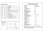
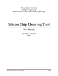
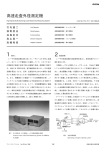
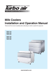
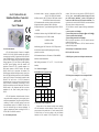
1.0 General introduction:
RS-422, RS-485 interface 600W lightning strike and surge
switches. The left one is a select switch for DTE, DCE of RS-232
interface. Note: switch to DCE position if connect PC serial
port (DTE interface definition) ; switch to DTE position if
connect other RS-232 devices (DCE interface definition). The
right is the select switch for RS-422/RS-485 conversion mode and
the user may select according to own needs.
ATC-105 interface converter supports following communication
modes:
1. point to point/4 wire full duplex
2. point to multi-point/4 wire full duplex(Four wire RS-485)
3. point to point/dual-line half duplex
4. point to multi-point/ dual-line half duplex
RS-232 to RS-422 conversion: set ATC-105 interface converter
switch to RS-422 position.
RS-232 to RS-485 conversion: set ATC-105 interface converter
switch to RS-485 position.
5.0 Sketch map for communication connection
ATC-105 Isolation Interface Converter is compatible
with RS-232C, RS-422, RS-485 standards and capable of
converting single end RS-232 signal into RS-422 or RS-485
signal of balanced signal. The built in photoelectric isolator
can offer 3500V isolation voltage and the rapid Transient
Voltage Suppressor (TVS) can effectively inhibit lightning
and ESD, prevent lightning strike and common code
interference. Connect PC, IPC, or portable computer via a
DB9 female connector at RS-232 interface, and connect
RS-422, RS-485 end via convenient 4-bit terminal. The
RS-485 supports dual-line half duplex, namely, the only two
lines of RS-485 shall both send and receive data. Handshake
signal (e.g. RTS, Request To Send) usually controls the data
direction. The inner circuit of ATC-105 Photoelectric
Isolation Interface Converter can detect data direction and
switch to control it automatically, conveniently to form a
RS-485 network without any shake hand signal. This kind of
RS-485 control is fully transparent and need no software
amendment for the former working modes basing on
RS-232.
protection on each line
RS-232 to RS-422 conversion
RS-232 TO RS-422/RS-485
Isolation Interface Converter
ATC-105
User’s Manual
2.1 Interface feature:
interface is compatible with EIA/TIA
RS-232C, RS- 485/RS-422 standard
2.2 Electric interface: RS-232C interface DB9 Female connector
RS-422/RS-485 interface 4-bit terminal
2.3 Transmission media: twisted-pair cable or shielded cable
2.4 operation mode: asynchronous half or full duplex
2.5 Signal indication: 3 signal indication lights indicate TD, RD
and PWR
2.6 Isolation: isolation voltage 3500VRMS 500VDC sequence
2.7 Transmission speed: 115.2K BPS to 300M
38.4K BPS to 2.4KM
9600 BPS to 5KM
2.8 Protecting grade: RS-232 interface+15KV ESD protection,
ATC-105 Photoelectric Isolation Interface Converter
can provide credible connection for point to point, point to
multi-point communication. The point to multi-point allows
connecting 32 RS-422 or RS-485 interface devices with
data transmission speed of 0-115.2KBPS. The dual color
data flow indication light can indicate malfunction. It
supports communication modes including RS-232C to
RS-422, RS-232 to RS-485 conversion.
2.0
Performance parameter
2.9 Transmission distance: 0-5 kilometers (115200-9600BPS)
5.1RS-422 point to point/4 wire full duplex communication
2.10 Size: 85mmx54mmx25mm
2.11 Working environment: -25℃ to 70℃,
5% to 95% relative
humidity
3.0
Connector and signal
RS-232 DB9 Female Connector Pinout
RS-232
DB9 Female
PIN2
5.2. RS-422 point to multi-point/4 wire full duplex RS-485
TXD
PIN3
RXD
PIN5
GND
RS-422/485 Terminal Pinout:
Terminal
1
2
3
No
4
RS-422
T+
T-
R-
R+
RS-485
485+
485-
-
-
4.0 Installation setup and application:
Please read the User’s Manual carefully before installing
ATC-105 Photoelectric Isolation Interface Converter. Insert the
power converter of the product into +9V socket, connect RS-422
or RS-485 device at one end according to the pin definition
instruction of 4-bit terminal. ATC-105 product has 2 toggle
5.3. Full duplex communication connection between ATC-105
interface converters
5.6 Half duplex communication connection between ATC-105
interface converters
6.0 Trouble shooting
RS-232 to RS-485 conversion
5.4 RS-485 point to point/ dual-line half duplex
6.1 Data transmission failure:
A. check to make sure the RS-232 interface is correctly connected
B. check to make sure the RS-422 interface is correctly connected
C. check to make sure the RS-485 interface is correctly connected
D. check to make sure the power supply is normal
E. check to make sure the switch setup is in the correct conversion
mode
F. check to make sure the DTE, DCE switch is in the correct
5.5 RS-485 point to multi- point /dual-line half duplex
interface setup mode. Note: switch to DCE position if
connect PC serial port (DTE interface definition) ; switch
to DTE position if connect other RS-232 devices (DCE
interface definition) . When the toggle switch on the left of
ATC-105 interface converter is on DCE position, the inner
definition of DB9 female RS-232 interface is: PIN2 is TXD,
PIN3 is RXD. When the toggle switch on its left is on DTE
position, the inner definition of DB9 female RS-232
interface is: PIN2 is RXD, PIN3 is TXD.
6.2 Data loss or error:
A. Check the consistency of the data speeds and formats at the
both ends of the data communication device.