1
User Manual
HD Visual Communication Unit
Model No.
KX-VC1300/KX-VC1600
Thank you for purchasing this Panasonic product.
Please read this manual carefully before using this product and save this manual for future use.
KX-VC1300/KX-VC1600: Software File Version 4.10 or later
In this manual, the suffix of each model number (e.g., KX-VCA001XX) is omitted unless necessary.
In this manual, HD Visual Communication is abbreviated as "HDVC".
Document Version: 2014-11
Introduction
Introduction
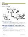
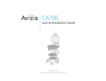
Feature Highlights
Display
Display
Video
camera
Computer
Microphone
Display
Internet
Computer
Display
Video
camera
Intranet
Router
Video
camera
NAT Traversal
Service
Microphone
Microphone
Router
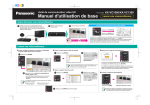
Lifelike Video Conference Call
You can experience lifelike video conference calls with smooth, high-quality video and clear stereo*1 sound.
*1
If using 2 or more Digital Boundary Microphones, stereo output can be enabled through system settings (Page 105). When using
Digital Boundary Microphones and an Analogue Boundary Microphone together, stereo output may be unavailable depending on the
connection configuration (Page 27, Page 29).
Home Electronics-style Remote Control Operation and Simple, Easy to
Understand Graphical User Interface
You can make settings and perform operations using familiar remote control operations and a simple, easy to
understand interface.
Stabilised Communication Quality
In periods of network congestion, automatic packet transmission rate quality control prevents packet loss to
maintain a video conference call’s image and sound quality. This allows video conference calls with stabilised
communication quality even over an Internet connection or mobile communication.
2
User Manual
Document Version 2014-11
Introduction
Dual stream (2 screens) compatible
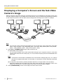
You can send the image of your video camera and the image of your computer’s screen or a sub video camera
at the same time to the other party.
You can view the other party and check shared data at the same time to hold more realistic and interactive
meetings.
Dual network compatibility (KX-VC1600 only)
You can connect to different networks at the same time, such as your company’s internal network and the
Internet. This allows seamless connectivity with units both inside and outside of your company.
Multi-party connections
The KX-VC1300 has a built-in MCU and can establish multiple connections with a maximum of 4 parties. The
KX-VC1600 can establish multiple connections with a maximum of 6 parties standard, and is expandable to a
maximum of 10 parties. All devices have MCU functions built-in, allowing for flexible connectivity.
Note
•
In this manual, 1 unit with a built-in MCU which connects to multiple sites simultaneously is referred
as to the "Main Site", and the sites connecting to the Main Site are referred to as "Sub Sites". A site
that establishes connections to multiple sites using a Profile Call (Page 49), or a site that adds a site
to the call during a 2-party video conference call with another site (Page 60) becomes the "Main
Site".
Selectable Video Source
By connecting your computer or video camera to the unit, you can show your computer’s screen or video
camera image to video conference call participants (Page 72).
Encrypted Communication
Packets sent for video conference calls can be encrypted to prevent packet leaks, tampering, or
eavesdropping.
KX-VC Series NAT Traversal Service
"KX-VC Series NAT Traversal Service" is a service that allows you to easily and affordably set up and operate
a communication environment for the HD Visual Communication Unit.*1*2 Also, complicated router configuration
is unnecessary, which allows even people who are not network administrators set up a communication
environment. Furthermore, you can assign the unit a unique number (Terminal ID), which allows the unit to be
called not by IP address, but with the unique 7-digit number. This means communication can be initiated as if
calling a telephone. Communication can also be encrypted, so that you can communicate over the Internet
safely and securely.
For details about KX-VC Series NAT Traversal Service, refer to the following web site:
http://panasonic.net/psn/products/hdvc/nat_traversal/index.html
*1
*2
This service may be unavailable depending on the country/area of use. For details, contact your dealer.
This service may be unavailable depending on your router’s type or your Internet connection environment. For details, contact your
dealer.
Document Version 2014-11
User Manual
3
Introduction
Making Video Conference Calls via SIP Server
By using a SIP server, you can establish video conference calls not just by IP address, but also by specifying
a SIP URI (SIP user name@SIP domain name) instead. If the other party uses the same SIP domain name
as you, you can make a video conference call by specifying only the SIP user name. For information about
supported SIP servers, contact your dealer.
Calling via an H.323 Gatekeeper
Going through an H.323 Gatekeeper allows communication of not just the IP address, by the H.323 extension
and the H.323 name as well. Contact your dealer regarding the gatekeepers that can be used.
Enhanced Features through the Use of Activation Keys
By using an activation key (sold separately), you can upgrade the features of the unit (Page 17). This allows
enrollment in the KX-VC Series NAT Traversal Service, and if using the KX-VC1600, multiple connections with
up to 10 parties simultaneously.
Remote Video Camera Operation via Remote Control
You can move your own video camera up, down, left, and right as well as zoom in and out (Page 75). You
can also register up to 9 preset patterns of video camera direction and zoom level which allows you to easily
change the video camera’s direction and zoom level by selecting a preset (Page 78, Page 80). Additionally,
you can also use your remote control to control the other party’s video camera.*1
*1
4
To be able to control another party’s video camera, settings must be configured on the other party’s unit (Page 108).
User Manual
Document Version 2014-11
Introduction
Trademarks
•
•
•
•
•
HDMI is a trademark or registered trademark of HDMI Licensing LLC in the United States and other
countries.
Polycom® is a trademark owned by Polycom, Inc. in the US and other countries.
Microsoft, Windows and Internet Explorer are either registered trademarks or trademarks of Microsoft
Corporation in the United States and/or other countries.
Mozilla and Firefox are registered trademarks of the Mozilla Foundation.
All other trademarks identified herein are the property of their respective owners.
Licences
•
•
•
THIS PRODUCT IS LICENSED UNDER THE AVC PATENT PORTFOLIO LICENSE FOR THE
PERSONAL USE OF A CONSUMER OR OTHER USES IN WHICH IT DOES NOT RECEIVE
REMUNERATION TO (i) ENCODE VIDEO IN COMPLIANCE WITH THE AVC STANDARD (“AVC
VIDEO”) AND/OR (ii) DECODE AVC VIDEO THAT WAS ENCODED BY A CONSUMER ENGAGED IN A
PERSONAL ACTIVITY AND/OR WAS OBTAINED FROM A VIDEO PROVIDER LICENSED TO PROVIDE
AVC VIDEO. NO LICENSE IS GRANTED OR SHALL BE IMPLIED FOR ANY OTHER USE. ADDITIONAL
INFORMATION MAY BE OBTAINED FROM MPEG LA, L.L.C. SEE HTTP://WWW.MPEGLA.COM
This product incorporates G.722.1 and G.722.1 Annex C licensed by Polycom®.
This product incorporates Qt library licenced by Digia Plc. Please read "EULA" of system settings of this
product.
Open Source Software
Parts of this product use Open Source Software supplied based on the conditions of the Free Software
Foundation’s GPLs and/or LGPLs and other conditions. Relevant conditions apply to this software. Therefore,
please read license information about GPLs and LGPLs, and "License Info." of system settings of this product
before using this product. Also, some software parts of this product are licensed under the MOZILLA PUBLIC
LICENSE (MPL). At least three (3) years from delivery of products, Panasonic will give to any third party who
contacts us at the contact information provided below, for a charge of no more than the cost of physically
distributing source code, a complete machine-readable copy of the corresponding source code and the
copyright notices covered under GPL, LGPL, and MPL. Please note that software licensed under GPL, LGPL,
and MPL is not under warranty.
Contact Information
http://www.panasonic.net/corporate/global_network/
Miscellaneous
About the Screen Shots and Illustrations in this Manual
The screen shots, illustrations and descriptions in this manual are based on using the KX-VC1600 (when used
with enhanced features). If you are using the KX-VC1300 or KX-VC1600 (without using the enhanced features),
please note that some displayed features will not be available for your model.
Copyright
The software used in this product uses source code from Radvision Ltd.
Document Version 2014-11
User Manual
5
Introduction
Portions of this software are © 1996-2012 RADVISION Ltd. All intellectual property rights in such portions of
the Software and documentation are owned by RADVISION and are protected by United States copyright laws,
other applicable copyright laws and international treaty provisions. RADVISION and its suppliers retain all rights
not expressly granted.
6
User Manual
Document Version 2014-11
Table of Contents
Table of Contents
For Your Safety ......................................................................................10
For Your Safety ...............................................................................................................10
Before Operation ....................................................................................12
Notes about Operation ...................................................................................................12
Data Security ...................................................................................................................13
Privacy and Right of Publicity .......................................................................................13
Precaution ...............................................................................................14
Precaution ........................................................................................................................14
Preparation .............................................................................................16
Accessory/Optional Accessory Information ................................................................16
Optional Accessory ........................................................................................................16
Part Names and Usage ...................................................................................................18
Main Unit (Front) ............................................................................................................18
Main Unit (Back) .............................................................................................................19
Remote Control ..............................................................................................................21
LED Indication ................................................................................................................23
Screen Standby ..............................................................................................................23
Connection and Preparation ..........................................................................................25
Device and Network Connection ....................................................................................25
Connecting the Unit ........................................................................................................26
Network Configuration Example .....................................................................................33
Preparing the Remote Control ........................................................................................35
Turning the Power On/Off ..............................................................................................36
Screen Display ................................................................................................................37
Home Screen (Idle Screen) ............................................................................................37
Menu Screen (Idle Screen) ............................................................................................39
Video Conference Call Screen .......................................................................................40
Entering characters ........................................................................................................42
Initial Settings ..................................................................................................................43
Starting a Video Conference .................................................................46
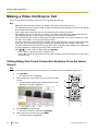
Making a Video Conference Call ....................................................................................46
Calling Using One-Touch Connection Numbers From the Home Screen ......................46
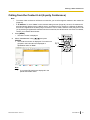
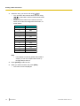
Calling from the Contact List (2-party Conference) ........................................................47
Calling Using Profile (Multiple-party Video Conference Calls) .......................................49
Calling by Entering an Address Directly .........................................................................51
Calling from the Call History ...........................................................................................53
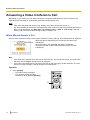
Answering a Video Conference Call ..............................................................................56
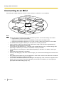
Connecting to an MCU ....................................................................................................58
During Video Conference Calls ............................................................60
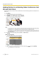
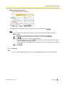
Adding Parties to an Existing Video Conference Call (Except Sub Sites) ................60
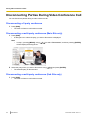
Disconnecting Parties During Video Conference Call .................................................62
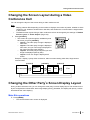
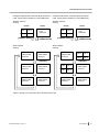
Changing the Screen Layout during a Video Conference Call ...................................63
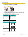
Changing the Other Party’s Screen Display Layout ....................................................63
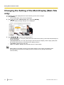
Changing the Setting of the Main Display (Main Site only) .........................................66
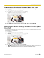
Changing the Site Name Display (Main Site only) .......................................................67
Changing the Audio Settings for Other Parties (Main Site only) ................................67
Adjusting the Volume .....................................................................................................68
Document Version 2014-11
User Manual
7
Table of Contents
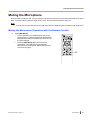
Muting the Microphone ...................................................................................................69
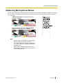
Reducing Microphone Noise ..........................................................................................71
Displaying a Computer’s Screen and the Sub Video Camera’s Image ......................72
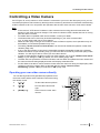
Controlling a Video Camera ..................................................................75
Controlling a Video Camera ...........................................................................................75
Registering a Preset .......................................................................................................78
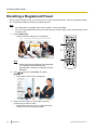
Recalling a Registered Preset ........................................................................................80
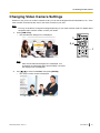
Changing Video Camera Settings .................................................................................81
Displaying the Connection Status ........................................................86
Displaying the Connection Status .................................................................................86
Displaying Unit Information ...........................................................................................87
Contacts and Settings ...........................................................................88
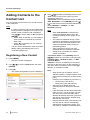
Adding Contacts to the Contact List .............................................................................88
Registering a New Contact .............................................................................................88
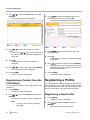
Editing Contact Information ............................................................................................89
Deleting a Contact ..........................................................................................................89
Registering a Contact from the Call History ...................................................................90
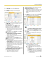
Registering a Profile .......................................................................................................90
Registering a New Profile ...............................................................................................90
Editing Profile Information ..............................................................................................92
Deleting a Profile ............................................................................................................92
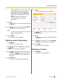
Making Local Site Settings .............................................................................................93
Registering a Local Site .................................................................................................93
Selecting a Local Site .....................................................................................................94
Deleting Local Site Information ......................................................................................94
Changing System Settings/Performing System Maintenance ....................................96
Setting the Unit Name ....................................................................................................99
Setting the Date and Time ..............................................................................................99
Making Network Settings ................................................................................................99
Making Connection Settings .........................................................................................100
Setting the MCU ...........................................................................................................102
Setting One-touch Connection Numbers ......................................................................104
Making Screen Standby Settings .................................................................................104
Making Sound Settings ................................................................................................104
Setting the MIC Position ...............................................................................................105
Making Remote Control Settings ..................................................................................107
Changing Video Camera Settings ................................................................................108
Making Language Settings ...........................................................................................108
Display Unit Information ...............................................................................................109
Checking Enhanced Features ......................................................................................109
Performing a Network Test ...........................................................................................109
Performing Self Diagnosis ............................................................................................109
Displaying the Licence Information ..............................................................................110
Displaying the End-User Licence Agreement ...............................................................110
Performing Remote Maintenance .................................................................................110
Making Administrator Menu Settings ..........................................................................111
Administrator Menu List ................................................................................................111
Making Administrator Password Settings .....................................................................115
Making Encryption Settings ..........................................................................................115
Making Software Update Settings ................................................................................116
Making Connection Mode Settings ...............................................................................116
Making NAT Settings ....................................................................................................117
8
User Manual
Document Version 2014-11
Table of Contents
Making Call Type Settings ............................................................................................118
Making SIP Settings .....................................................................................................118
Making H.323 Settings .................................................................................................120
Making Codec Settings ................................................................................................121
Making Video Output Settings ......................................................................................122
Making Audio Input/Output Settings .............................................................................124
Making GUI Settings ....................................................................................................124
Making HDMI Settings ..................................................................................................125
Setting Shortcuts ..........................................................................................................125
Setting Local Site Selection ..........................................................................................126
Exporting Data ..............................................................................................................126
Importing Data ..............................................................................................................127
Activating Enhanced Features .....................................................................................128
Updating Software ........................................................................................................128
Initialising a Video Camera ...........................................................................................129
Performing System Initialisation ...................................................................................130
Using the KX-VC Series NAT Traversal Service ................................131
Using the KX-VC Series NAT Traversal Service .........................................................131
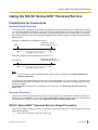
Preparations for Connections .......................................................................................131
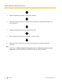
KX-VC Series NAT Traversal Service Setup Procedure ..............................................131
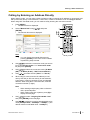
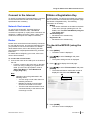
Connect to the Internet .................................................................................................133
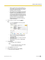
Obtain a Registration Key ............................................................................................133
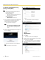
To check the MPR ID (using the unit) ........................................................................133
To obtain a Registration Key (using a computer) ......................................................134
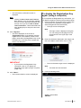
To display the Registration Key again (using a computer) ........................................135
Miscellaneous .......................................................................................139
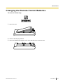
Changing the Remote Control Batteries .....................................................................139
Cleaning the Unit ...........................................................................................................140
Input ......................................................................................................141
Inputting Letters and Numbers ....................................................................................141
Additional Information .........................................................................150
Troubleshooting ............................................................................................................150
Basic Operation ............................................................................................................150
Audio ............................................................................................................................155
System Settings ...........................................................................................................157
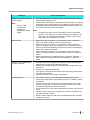
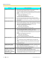
If These Messages Appear ..........................................................................................157
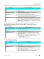
Registration Page of KX-VC Series NAT Traversal Service ........................................163
KX-VC Series NAT Traversal Service for this Device ..................................................164
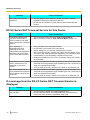
If a message from the KX-VC Series NAT Traversal Service is displayed ..................164
Specifications .......................................................................................167
System Specifications ..................................................................................................167
Index............................................................................................................170
Document Version 2014-11
User Manual
9
For Your Safety
For Your Safety
For Your Safety
CAUTION
CAUTION:
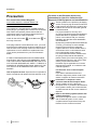
• Before attempting to connect or operate this
product, please read the label on the bottom.
Be sure to use the specified type of batteries only.
Ensure that batteries are installed with correct
polarity. Incorrectly installed batteries can burst or
leak, resulting in spillage or injuries.
This product contains batteries. Replace only with
the same or equivalent type. Improper use or
replacement may cause overheating, rupture or
explosion resulting in injury or fire. Dispose of used
batteries according to the instructions of your local
solid waste officials and local regulations.
When replacing the batteries for the remote control,
use R6 (AA) type dry cell.
•
•
RISK OF ELECTRIC SHOCK
DO NOT OPEN
•
CAUTION: TO REDUCE THE RISK OF ELECTRIC SHOCK,
DO NOT REMOVE COVER (OR BACK).
NO USER-SERVICEABLE PARTS INSIDE.
REFER SERVICING TO QUALIFIED SERVICE PERSONNEL.
The lightning flash with arrowhead
symbol, within an equilateral triangle, is
intended to alert the user to the presence
of uninsulated "dangerous voltage" within
the product’s enclosure that may be of
sufficient magnitude to constitute a risk of
electric shock to persons.
The exclamation point within an
equilateral triangle is intended to alert the
user to the presence of important
operating and maintenance (servicing)
instructions in the literature
accompanying the appliance.
WARNING:
• The mains plug or an appliance coupler shall
•
•
•
•
•
•
•
10
remain readily operable.
To prevent fire or electric shock hazard, do not
expose this apparatus to rain or moisture.
The apparatus should not be exposed to dripping or
splashing and no objects filled with liquids, such as
vases, should be placed on the apparatus.
All work related to the installation of this product
should be made by qualified service personnel or
system installers.
The connections should comply with local electrical
code.
Batteries (battery pack or batteries installed) shall
not be exposed to excessive heat such as sunshine,
fire or the like.
This is a class A product. In a domestic environment
this product may cause radio interference in which
case the user may be required to take adequate
measures.
This equipment is compliant with Class A of CISPR
32. In a residential environment this equipment may
cause radio interference.
User Manual
•
For use only with power supply Panasonic,
PGLV1006.
Important Safety Instructions:
1)
Read these instructions.
2)
Keep these instructions.
3)
Heed all warnings.
4)
Follow all instructions.
5)
Do not use this apparatus near water.
6)
Clean only with dry cloth.
7)
Do not block any ventilation openings. Install
in accordance with the manufacturer’s
instructions.
8)
Do not install near any heat sources such as
radiators, heat registers, stoves, or other
apparatus (including amplifiers) that produce
heat.
9)
Protect the power cord from being walked on
or pinched particularly at plugs, convenience
receptacles, and the point where they exit
from the apparatus.
10)
Only use attachments/accessories specified
by the manufacturer.
11)
Unplug this apparatus during lightning storms
or when unused for long periods of time.
Document Version 2014-11
For Your Safety
12)
Refer all servicing to qualified service
personnel. Servicing is required when the
apparatus has been damaged in any way,
such as power-supply cord or plug is
damaged, liquid has been spilled or objects
have fallen into the apparatus, the apparatus
has been exposed to rain or moisture, does
not operate normally, or has been dropped.
Document Version 2014-11
User Manual
11
Before Operation
Before Operation
Notes about Operation
Please pay attention to the following points when using
this device:
1. Please contact your dealer for installing,
upgrading, or repairing this device.
10. Avoid placing the device in areas with high
humidity, and exposing it to rain.
Neither the main unit nor the power plug is water
resistant.
11. The power outlet should be near the product
and easily accessible.
2. Do not forcefully hit or shake this device.
Dropping or bumping this device can damage or
break this device.
3. Do not place this device in a freezer or other
location where it is exposed to cold
temperatures.
Doing so may result in damage or malfunctions.
4. Place this device at least 2 m (6.5 ft) away from
radios, office equipment, microwave ovens, air
conditioning units, etc.
Noise from electronic devices can cause static and
interference in other devices.
5. Do not place this device in a location where it is
exposed to hydrogen sulfide, phosphorous,
ammonia, sulfur, carbon, acid, dirt, toxic gas,
etc.
Doing so may result in damage, and the usable
life-span of the device may decrease.
6. Do not apply insecticides or other volatile
liquids to the device, nor leave rubber bands or
vinyl objects on the device for extended periods
of time.
Doing so may result in alterations to the material or
paint peeling off the device.
About the Operating Environment
This device includes a feature that automatically adjusts
voice transmissions to improve clarity. After beginning
a video conference call, adjustments to the call
environment may not complete immediately, and as a
result voices may cut out or echo. In such cases, at the
beginning of the video conference call, be sure to speak
in turn with other parties.
About Moving the Device
Do not move this device while cords are still connected.
Doing so may result in damage to the cords.
Other
•
•
The unit may not operate in the event of a power
failure.
After unpacking the product, dispose of the power
plug cap and packing materials appropriately.
7. Do not bring cards with magnetic strips, such
as credit cards and telephone cards, near the
microphone.
Cards might become unusable.
8. Do not bring the device near items that emit
electromagnetic waves or that are magnetised
(high-frequency sewing machines, electric
welders, magnets, etc.).
Doing so may result in static noise or damage.
9. Keep the device at least 10 cm (4 in) away from
all walls.
If placed against a wall, the device may not be able
to ventilate properly, which may lead to a system
malfunction due to overheating.
12
User Manual
Document Version 2014-11
Before Operation
Data Security
We recommend observing the security precautions
described in this section, in order to prevent the
disclosure of sensitive information.
Panasonic is not responsible for any damages
caused by improper use of this device.
Preventing Data Loss
Privacy and Right of
Publicity
By installing and using this device, you are responsible
for maintaining the privacy and usage rights of images
and other data (including sound picked up by the
microphone). Use this device accordingly.
•
Keep a separate record of the encryption key and all
information stored in the contact list.
Preventing Data Disclosure
•
Do not place this device in a location that can be
accessed or removed without authorisation.
• If important information is saved on this device,
store it in an appropriate location.
• Do not store sensitive personal information in the
unit.
• In the following situations, make a record of the
encryption key and the information stored in the
contact list and return the unit to the state it was in
when purchased.
– Before lending or disposing of the unit
– Before handing the unit over to a third party
– Before having the unit serviced
• Make sure the unit is serviced by only a certified
technician.
This device can register and store personal data (the
contact list, encryption key, connection history, etc.). In
order to prevent the disclosure of data stored on this
device, make sure to delete all data that is registered
and stored on this device prior to disposing of, lending,
or returning this device.
•
Privacy is generally said to be, "A legal guarantee
and right not to have the details of one’s personal
life unreasonably publicised, and the right to be able
to control information about oneself. In addition,
right of publicity is a right not to have a likeness of
one’s face or figure photographed and publicised
without consent".
When the Automatic Answer feature is enabled,
transmission begins as soon as a video conference
call is received. The receiver of the video
conference call will begin transmitting as soon as
the video conference call is received at any time,
from any caller. Please be aware when the
Automatic Answer feature is enabled, there is a risk
that due to an unexpected, automatically answered
video conference call, privacy rights may be
violated or sensitive information may be transmitted
to unauthorised parties.
Preventing Data Disclosure over the
Network
•
•
•
•
To ensure the security of private conversations,
only connect the unit to a secure network.
To prevent unauthorised access, only connect the
unit to a network that is properly managed.
Make sure all computers connected to the unit
employ up-to-date security measures.
To prevent illegal access from the Internet, activate
a Firewall.
Document Version 2014-11
User Manual
13
Precaution
Precaution
For users in the European Union only
Information for Users on Collection and
Disposal of Old Equipment and used Batteries
Precaution
For users in the United Kingdom
FOR YOUR SAFETY, PLEASE READ THE
FOLLOWING TEXT CAREFULLY.
This appliance is supplied with a moulded three-pin
mains plug for your safety and convenience. Should the
fuse need to be replaced, please ensure that the
replacement fuse is of the same rating and that it is
approved by ASTA or BSI to BS1362.
Check for the ASTA mark
or the BSI mark
on
the body of the fuse.
If the plug contains a removable fuse cover, you must
ensure that it is refitted when the fuse is replaced. If you
lose the fuse cover, the plug must not be used until a
replacement cover is obtained. A replacement fuse
cover can be purchased from your local Panasonic
dealer.
IF THE FITTED MOULDED PLUG IS UNSUITABLE
FOR THE AC OUTLET IN YOUR PREMISES, THEN
THE FUSE SHOULD BE REMOVED AND THE PLUG
CUT OFF AND DISPOSED OF SAFELY. THERE IS A
DANGER OF SEVERE ELECTRICAL SHOCK IF THE
CUT-OFF PLUG IS INSERTED INTO ANY 13 AMP
SOCKET.
How to replace the fuse: Open the fuse compartment
with a screwdriver and replace the fuse and fuse cover.
These symbols on the products, packaging,
and/or accompanying documents mean that
used electrical and electronic products and
batteries should not be mixed with general
household waste.
For proper treatment, recovery and
recycling of old products and used batteries,
please take them to applicable collection
points, in accordance with your national
legislation and the Directives 2002/96/EC
and 2006/66/EC.
By disposing of these products and batteries
correctly, you will help to save valuable
resources and prevent any potential
negative effects on human health and the
environment which could otherwise arise
from inappropriate waste handling.
For more information about collection and
recycling of old products and batteries,
please contact your local municipality, your
waste disposal service or the point of sale
where you purchased the items.
Penalties may be applicable for incorrect
disposal of this waste, in accordance with
national legislation.
For business users in the European
Union
If you wish to discard electrical and
electronic equipment, please contact your
dealer or supplier for further information.
Information on disposal in other
countries outside the European Union
These symbols are only valid in the
European Union. If you wish to discard these
items, please contact your local authorities
or dealer and ask for the correct method of
disposal.
Note for the battery symbol (bottom two
symbol examples):
This symbol might be used in combination
with a chemical symbol. In this case it
complies with the requirement set by the
Directive for the chemical involved.
14
User Manual
Document Version 2014-11
Precaution
For users in Taiwan only
Notice
•
This product contains a CR coin lithium battery.
When disposing of the product, the battery must
be removed. Contact your dealer for details.
Direct current symbol
Alternating current symbol
We declare under our sole responsibility that the
product to which this declaration relates is in
conformity with the standards or other normative
documents following the provisions of Directives
2006/95/EC and 2004/108/EC.
Document Version 2014-11
User Manual
15
Preparation
Preparation
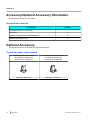
Accessory/Optional Accessory Information
The following accessories are included:
Included Accessories
Accessories
Quantity
AC adaptor (Part No.: PGLV1006)
1
Power cord
3
Remote control (Part No.: N2QAYB001001)
1
Batteries (R6 [AA] dry cell)
2
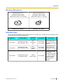
Optional Accessory
The following products are available as optional accessories.
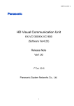
Proprietary main video camera
16
Proprietary main video camera
12x optical/10x digital zoom
Pan/tilt function supported
Proprietary main video camera
3x optical/4x digital zoom
Pan/tilt function supported
Model No.: GP-VD151
Model No.: GP-VD131
User Manual
Document Version 2014-11
Preparation
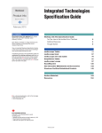
Boundary Microphone
Boundary Microphone
(Digital Interface Type)
(Proprietary cable included.
Cable length: approx. 8.5 m [28 ft])
Boundary Microphone
(Analogue Interface Type)
(Proprietary cable included.
Cable length: approx. 7 m [23 ft])
Model No.: KX-VCA001
Model No.: KX-VCA002
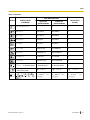
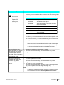
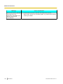
Activation Keys
You can enhance the following types of features with an activation key. For details about the settings, refer to
"Activating Enhanced Features" (Page 128).
Model No.
Product Name
Activation
Key Type
Target Model
Description
KX-VCS701
Activation Key Card
(NAT Traversal 1 Year)
NAT
Traversal 1
Year
KX-VC1300
KX-VC1600
Extends the service
period of KX-VC
Series NAT Traversal
Service.
KX-VCS703
Activation Key Card
(NAT Traversal 3 Year)
NAT
Traversal 3
Years
KX-VC1300
KX-VC1600
Extends the service
period of KX-VC
Series NAT Traversal
Service.
KX-VC1600
Enables the feature
for making
multiple-party video
conference calls with
10 parties, rather
than the default
maximum of 6
parties.
KX-VCS304
Document Version 2014-11
Activation Key Card (4
Point Built-in MCU)
4 Point
Built-in MCU
User Manual
17
Preparation
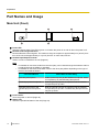
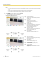
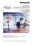
Part Names and Usage
Main Unit (Front)
A
D
B
C
E
Power LED
Shows the power status. The LED is green or red when the power is on and off when the power is off.
Remote Control Signal Receiver
Receives Remote Control signals. The maximum range of reception is approximately 8 m (26.2 ft) from
front of the unit, and approximately 3 m (9.8 ft) from 20° on each side, total 40°.
Headset Input-Output Terminal
Used to connect a headset to the unit (Page 30).
Note
•
•
If a headset is connected, audio from the other party can be heard through the headset. Audio is
not played through the display or speakers.
If a headset is connected, how audio is sent to the other party differs depending on the type of
devices connected as follows:
Connected Device
Audio Sent to Other Party
Boundary Microphone
Audio is picked up only by the headset microphone. Audio
is not picked up by the Boundary Microphones.
General-purpose microphone
Both the general-purpose microphones and the headset
microphone pick up audio.
Boundary Microphone and
general-purpose microphone
Both the general-purpose microphones and the headset
microphone pick up audio. The Boundary Microphones do
not pick up audio.
Power button
Turns the power on and off (Page 36).
Status LED
Shows the operational status of the unit (Page 23).
18
User Manual
Document Version 2014-11
Preparation
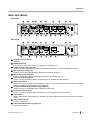
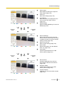
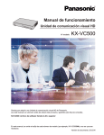
Main Unit (Back)
KX-VC1600
A
B
L
K
C D
M
N
E
O
F
P
G
Q
H
R
I
S
J
T
U
KX-VC1300
A
K
B
C D
M
N
E
O
F
P
G
Q
I
R
J
T
U
Camera Control terminal
Not used.
RS-232C terminal
Normally not used. Used to connect a computer for maintenance.
USB jack (Page 126, Page 128)
Used to connect a USB memory device for saving the operation log and for updating the software.
MIC (Digital) jack (Page 26)
Used to connect the Digital Boundary Microphone (optional) (Page 17).
MIC (Analog) jack (Page 26)
Used to connect the Analogue Boundary Microphone (optional) (Page 17).
Audio In L/R jack (Page 27)
Used to connect general-purpose microphones (not for the Boundary Microphone).
Audio Out L/R jack
Used to connect an amplifier or active speaker (Page 31). Also used to connect the speakers of a display
without an HDMI terminal for audio output (Page 32).
Component terminal (KX-VC1600 only) (Page 32)
Used to connect to the display with a component video cable.
Functional Earth terminal
Used to connect an earthing wire for when there is a lot of noise over the connection.
Video Switch
Used to set the unit’s video frequency. Sets the unit’s video frequency to be the same as the connected
device.
LAN1 jack (Page 27)
Connect a LAN cable.
LAN2 jack (KX-VC1600 only) (Page 27)
Connect a LAN cable.
Document Version 2014-11
User Manual
19
Preparation
RGB terminal (Page 30)
Used to connect a computer for sending screens to participants.
HDMI terminal (Page 30)
Used to connect a computer for sending screens to participants.
Sub Camera terminal (Page 30)
Used to connect a second, sub video camera with an HDMI cable for sharing video contents apart from
the main video camera.
Main Camera terminal (Page 26)
Connect the main video camera with an HDMI cable.
HDMI1 terminal (Page 26)
Used to connect to the display with an HDMI cable.
HDMI2 terminal (Page 26)
Used to connect to the display with an HDMI cable.
HDMI3 terminal (KX-VC1600 only) (Page 26)
Used to connect to the display or a video recorder with an HDMI cable. Used to switch the displayed image
between your image and recorded video.
DC IN (Page 27)
Connect the AC adaptor’s DC cord.
Hook
Used to prevent the DC IN connection from becoming unplugged.
20
User Manual
Document Version 2014-11
Preparation
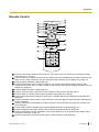
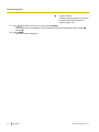
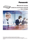
Remote Control
A
B
C
D
E
F
G
H
L
M
N
O
P
Q
R
S
I
T
J
K
Press to enter screen standby mode (Page 23). The power of the unit can be turned on/off by pressing
and holding (for 1 second).
Press to show your computer’s screen on your and the other party’s display during a video conference call.
When not on a video conference call, the computer screen is shown on your display only (Page 72).
Press to display the Menu screen (Page 39).
Press to show the sub video camera’s images on your and the other party’s display during a video
conference call. When not on a video conference call, the sub video camera’s images are shown on your
display only (Page 72).
Press to display the Home screen (Page 37).
Press to move the cursor, control the PT (Pan/Tilt) of a video camera, and select items.
Press to make or manually answer video conference calls (Page 46, Page 56).
Press to select the feature assigned to each colour. Available features are displayed in the guide area
(Page 38).
Press to adjust the volume during a video conference call. Press [+] to increase and [–] to decrease the
volume (Page 68).
Press to mute the microphone during a video conference call, so that the other party cannot hear your
voice (Page 69).
Press to dial or perform settings where inputting digits/characters is required (Page 141).
Press to display the connection status of the network and peripheral devices (Page 86).
Press to show/hide on-screen information, such as the guide area, on the Home screen and the video
conference call screen (Page 40).
Press to change the layout of the screen during a video conference call (Page 63).
Document Version 2014-11
User Manual
21
Preparation
Press to return to the main video camera after showing images from a computer or sub video camera
(Page 72).
Press to return to the previous screen.
Press to confirm the selected item or entered information.
Press to end a video conference call.
Press to display the camera control screen (Page 76).
Press for zoom control (zoom in/out) of the video camera either at your end or the other party’s end
(Page 75).
22
User Manual
Document Version 2014-11
Preparation
LED Indication
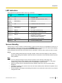
LEDs indicate the operational status of the unit, as follows:
Power
LED
Status LED
Status
Off
Off
•
AC power: OFF
Red on
Off
•
AC power: ON (Power button: OFF)
Green
flashing
Blue flashing
•
Starting up
Red
flashing
Off
•
A hardware fault has occurred.
Blue flashing
•
•
Startup state
Idle state
Green on
Blue on
•
In a video conference call
Green on
Yellow on
•
Self diagnosis is being performed.
Red on
•
•
•
An error has occurred.
Maintenance is being performed.
Software update in progress
Green on
Red flashing
•
A serious error has occurred.
Green on
Off
•
In screen standby mode
Green on
Green on
Screen Standby
When there is no video conference call transmission, and the remote control is not operated for more than 10
minutes (default), or when the remote control’s [STANDBY] button is pressed, the unit enters screen standby
mode. Video out to the display is suspended and the status LED turns off.
Screen standby mode ends when the remote control is operated, or when a video conference call is received.
Notice
•
If screen standby mode ends and no image is visible, check to see if the display or video camera’s
power saving settings are enabled. Check each device’s manual for more information about its power
saving settings.
Note
•
•
•
•
•
You can change the length of time until the unit enters screen standby mode (Page 104).
The unit will not enter screen standby mode while displaying a computer’s screen or a sub video
camera’s image, even if the remote control is not operated for a period of time.
When the remote control is operated and screen standby mode ends, the Home screen will be
displayed.
If a button is pressed on the remote control to end screen standby mode, that button’s operation is not
performed in that case.
If screen standby mode begins while editing information in the contact list or other screen, any unsaved
changes will be lost.
Document Version 2014-11
User Manual
23
Preparation
•
24
It takes about 7 seconds to return from screen standby mode. (The length of time may vary depending
on the type of display you are using.)
User Manual
Document Version 2014-11
Preparation
Connection and
Preparation
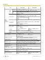
Device and Network Connection
In addition to the unit, you will need a video camera, a
display, a microphone (Boundary Microphone or
general-purpose microphone) and connection cables
for visual communication.
Apart from the Boundary Microphone, the other devices
must meet the following conditions:
Device
*1
Stereo pin plug cable (for connecting a
general-purpose microphone/amplifier/active
speaker/display [without an HDMI terminal and with
speakers]):
RCA plug
Network Environment
When using the unit over the Internet, a broadband
connection is required.
Condition
Video
Camera
HDMI output required (resolution:
1080p/1080i/720p)
Display*1
HDMI/component input required
Make sure that the video
frequencies of the unit and display
match.
Generalpurpose
microphone
Line level output required (In case of
microphone level output,
microphone amplifier also required)
If displays are connected using both the HDMI terminal and
Component terminal, connect to displays that have the same
resolution (Page 123).
Cables
Prepare the following commercially available cables:
HDMI cable:
Category 2 (high speed) recommended
Note
•
Use cables with the HDMI logo (certified
HDMI cables) for HDMI connection. Using
non-certified cables may adversely affect
operation. Use HDMI cables with secure
connectors.
LAN cable:
100BASE-TX (full duplex)
Category 5 or greater
VGA cable (for computer connection when using
the secondary video source):
15-pin mini D-Sub
Note
•
Ensure that the cables match the sockets of
both the unit and your computer.
Document Version 2014-11
User Manual
25
Preparation
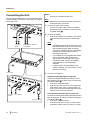
Connecting the Unit
Notice
This section describes how to connect the main video
camera, display, microphone, LAN cable, AC adaptor
and power cord.
Note
•
•
Use only the included power cord.
Make sure to read the instruction manuals for
all devices being connected.
1. Connect the main video camera.
• Connect the main video camera to the Main
Camera terminal on the back of the unit using
an HDMI cable (A).
C
D
2. Connect the display.
• Connect the display to the HDMI 1-3 terminals
E
on the back of the unit using an HDMI cable
(B).
Note
To each
device
To a general - purpose
microphone
•
•
F
•
To a router
3. Connect a microphone.
Digital Boundary Microphone (optional)
Connect the Digital Boundary Microphone to the
MIC (Digital) jack on the back of the unit using the
proprietary cable (C).
• Use only the included cable.
• Push and turn the connector of the proprietary
cable until it clicks. If the connector does not
click, try reconnecting the cable with the top and
bottom of the connector reversed.
A
B
G
To each To a display
device
To an AC outlet
26
User Manual
The HDMI3 terminal on the back of the unit
switches between output of your own image
and recorded images. When recording,
connect the recording device to the HDMI3
terminal, and set the output to that for
recording (Page 123).
If your display is not compatible with HDMI,
use a component cable. Since sound
signals are not transmitted when using a
component cable, connect an amplifier/
active speaker, or use the display’s
speakers.
If "game mode" can be selected in the
display’s settings, set "game mode". It may
improve voice delay.
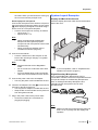
Analogue Boundary Microphone (optional)
Connect the Analogue Boundary Microphone to the
MIC (Analog) jack on the back of the unit using the
proprietary cable (D).
• Use only the included cable.
• Ensure that the arrow on the connector of the
proprietary cable is facing up when you insert
Document Version 2014-11
Preparation
the cable. When you disconnect the cable, grip
the connector securely and pull it out.
General-purpose microphone
Connect the microphone to the Audio In L/R jack on
the back of the unit using the stereo pin plug cable
(E) after amplifying the signal to line level using a
device such as a microphone amplifier.
• Connect the microphone correctly, as follows:
– Left channel ® L
– Right channel ® R
System Layout Examples
Display and Main Video Camera
Place the display and main video camera at the same
side of the room.
Note
•
•
When connecting both the Boundary
Microphone and a general-purpose
microphone, both microphones can be used
simultaneously.
When connecting a headset, refer to
"Headset Connection (Page 30)".
4. Connect to the network.
• Connect a hub/router to the LAN jack on the
back of the unit using a category 5 or greater
LAN cable (F).
Note
•
•
•
Set the hub/router to Auto Negotiation
mode.
Do not connect to a hub/router set to Half
Duplex.
For more details about routers and DCEs,
refer to the documentation for each device.
5. Connect the power cord to the AC adaptor.
• Use only the power cord included with the unit.
6. Insert the AC adaptor’s DC cord (G) into the DC IN
terminal on the back of the unit.
• Use only the AC adaptor included with the unit.
• Wrap the DC cord around the hook to prevent it
from being disconnected.
Note
•
If you use speakers, refer to "Amplifier/Active
Speaker Connection" (Page 31).
Digital Boundary Microphones
Up to 4 Digital Boundary Microphones can be
connected in cascade. There are no separate terminals
for input and output on the Boundary Microphones.
Also, an Analogue Boundary Microphone and
general-purpose microphones can be used
simultaneously.
7. Plug in the power cord into the power outlet.
• Choose an outlet that is convenient for
plugging/unplugging.
Note
•
Document Version 2014-11
Make sure that the microphones are placed at
least 1 m (3.3 ft) away from the display and
speakers.
User Manual
27
Preparation
•
Do not connect more than 4 Digital Boundary
Microphones. Doing so will cause all Digital
Boundary Microphones to stop working. If an
Analogue Boundary Microphone is also
connected, all audio input from the Analogue
Boundary Microphone will also stop working.
If both of the following conditions are met, the
output sent to the other party will be stereo;
otherwise, monaural:
– The bandwidth is higher than approximately
1.8 Mbps in a 2-party video conference call
with the HD Visual Communication Unit.
– The MIC position is set automatically or
manually to collect a sound in stereo.
If a headset is connected, audio from the
headset microphone is given priority, and audio
from Digital Boundary Microphones is no longer
picked up.
•
•
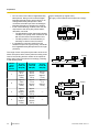
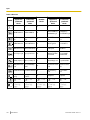
Layout examples (a regular room)
(the grey circle indicates the microphone’s range):
Display
4m
(13.1 ft)
Microphone
The range of each microphone (the radius of the circle
with a microphone at the centre) varies according to the
level of surrounding and the number of microphones
being used. Place microphones accordingly, referring
to the following table.
Noise
level/
Micro–
phone
A quiet
room (40
dBsplA)
A regular
room (45
dBsplA)
A noisy
room (50
dBsplA)
1
approx.
3m
(approx.
9.8 ft)
approx.
2.2 m
(approx.
7.2 ft)
approx.
1.2 m
(approx.
3.9 ft)
2
approx.
2.8 m
(approx.
9.2 ft)
approx.
1.5 m
(approx.
4.9 ft)
approx.
1m
(approx.
3.3 ft)
approx.
2.3 m
(approx.
7.5 ft)
approx.
1.3 m
(approx.
4.3 ft)
—
approx.
2m
(approx.
6.5 ft)
approx.
1.1 m
(approx.
3.6 ft)
—
3
4
28
User Manual
Display
Microphone
4m
(13.1 ft)
4m
(13.1 ft)
Microphone
4m
(13.1 ft)
4m
(13.1 ft)
Microphone
Microphone
Display
4m
(13.1 ft)
Microphone
Document Version 2014-11
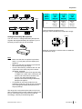
Preparation
Microphone
Microphone
4m
(13.1 ft)
4m
(13.1 ft)
Microphone
Microphone
4m
(13.1 ft)
Display
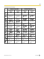
Noise
level/
Micro–
phone
A quiet
room
(40
dBsplA)
A regular
room
(45
dBsplA)
A noisy
room
(50
dBsplA)
1
approx.
2m
(approx.
6.5 ft)
approx.
1.5 m
(approx.
4.9 ft)
approx.
1m
(approx.
3.3 ft)
4m
(13.1 ft)
Layout examples (a regular room)
(the grey circle indicates the microphone’s range):
Display
Analogue Boundary Microphones
You can connect 1 Analogue Boundary Microphone.
Together with Digital Boundary Microphones, up to 5
boundary microphones can be connected.
2 m (6.5 ft)
Microphone
Approx.
60°
60
About 60° around the connector side is outside the
microphone’s range.
Note
•
•
•
•
Make sure that the microphone is placed at
least 1 m (3.3 ft) away from the display and
speakers.
Make sure that the microphone is placed with
its connector facing the display.
If both of the following conditions are met, the
output sent to the other party will be stereo;
otherwise, monaural:
– The bandwidth is higher than approximately
1.8 Mbps in a 2-party video conference call
with the HD Visual Communication Unit.
– You are not using Digital Boundary
Microphones and an Analogue Boundary
Microphone together.
If a headset is connected, audio from the
headset microphone is given priority, and audio
from Analogue Boundary Microphones is no
longer picked up.
The range of the microphone (the radius of the circle
with a microphone at the centre) varies according to the
level of surrounding noise. Place the microphone
accordingly, referring to the following table.
Document Version 2014-11
User Manual
29
Preparation
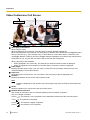
Headset Connection
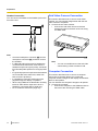
Sub Video Camera Connection
You can connect a headset to the headset jack on the
front of the unit.
This section describes how to connect a sub video
camera. You can transmit images taken with the sub
video camera to all parties.
1. Connect the sub video camera.
• Connect the sub video camera to the Sub
Camera terminal on the back of the unit using
an HDMI cable.
A
B
Headset
Note
•
•
•
•
•
•
30
Check the headphone connector (A) and the
microphone connector (B), and then connect
the headset.
If a Boundary Microphone and a headset are
connected at the same time, audio from the
headset microphone is given priority, and audio
from Boundary Microphones is no longer picked
up.
If a general-purpose microphone and a headset
are connected at the same time, audio from
both sources is picked up.
If a headset is connected, audio will not be
played through the display or speakers.
When using HDMI3 as a video/audio recording
terminal, audio will be output even when a
headset is connected. (KX-VC1600 only)
For 3-conductor stereo mini-plugs only.
User Manual
Note
•
You can connect/disconnect the sub video
camera during a video conference call.
Computer Connection
This section describes how to connect a computer.
Connecting a computer allows you to show the
computer screen’s images on the display and transmit
them to other parties.
You can transmit the computer’s images to all parties.
1. Connect the computer.
• Connect the computer to the HDMI terminal on
the back of the unit using an HDMI cable.
Document Version 2014-11
Preparation
•
For computers without HDMI ports, connect the
computer to the RGB terminal on the back of the
unit using a VGA cable.
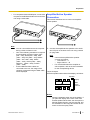
Amplifier/Active Speaker
Connection
This section describes how to connect an amplifier/
active speaker.
Note
•
•
•
You can connect/disconnect the computer
during a video conference call.
One of the following resolutions is required
for transmitting computer images: VGA
(640 ´ 480), SVGA (800 ´ 600), XGA
(1024 ´ 768), HD (1280 ´ 720), WXGA
(1280 ´ 768, 1280 ´ 800), SXGA
(1280 ´ 1024), UXGA (1600 ´ 1200),
WSXGA + (1680 ´ 1050), Full-HD
(1920 ´ 1080).
If both HDMI and VGA cables are
connected to the unit, the image of the
computer connected using an HDMI cable
will be displayed.
1. Connect the amplifier/active speaker to the Audio
Out L/R jack on the back of the unit using a stereo
pin plug cable.
Note
•
•
Connect the amplifier/active speaker
correctly, as follows:
– Left channel ® L
– Right channel ® R
For more details about the amplifier or
active speaker, refer to the documentation
for the corresponding device.
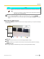
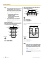
Layout example:
Place the speakers either side of the display, as follows:
Speaker
Display
Main
video
camera
Microphone
Speaker
Notice
•
Document Version 2014-11
Place the speakers either side of the display. If
you place the display at the front of the room
and the speakers at the back, the microphone’s
left/right spatial direction may be reversed, and
the orientation of the image and sound will not
match on the other party’s side.
User Manual
31
Preparation
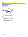
Connecting the Display with a
Component Cable
If your display does not have an HDMI terminal, use a
component cable for connection.
1. Connect the display to the Component terminal on
the back of the unit using a component cable.
Note
•
•
32
To use the display’s speakers to output audio,
connect the display to the Audio Out L/R jack
(Page 19) on the back of the unit using a stereo
pin plug cable.
If displays are connected using both the HDMI
terminal and Component terminal, connect to
displays that have the same resolution.
User Manual
Document Version 2014-11
Preparation
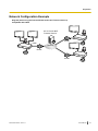
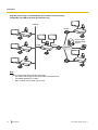
Network Configuration Example
Diagram (when using the Internet/KX-VC Series NAT Traversal Service)
Compatible with LAN1
KX-VC Series NAT
Traversal Service
Router
LAN1
Internet
Router
Router
Document Version 2014-11
User Manual
33
Preparation
Diagram (when using an intranet/KX-VC Series NAT Traversal Service)
Compatible with LAN1 and LAN2 (KX-VC1600 only)
Intranet
Router
LAN2
KX-VC Series
NAT Traversal
Service
LAN1
Internet
Router
Router
Note
When using a dual network (LAN1 and LAN2)
• Use LAN1 when using KX-VC Series NAT Traversal Service.
• The default gateway is in LAN1.
• NAT or DHCP can be used only in LAN1.
34
User Manual
Document Version 2014-11
Preparation
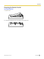
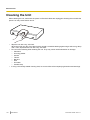
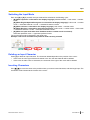
Preparing the Remote Control
Inserting Batteries
1. Open the cover.
2. Insert batteries (R6 [AA] dry cell), minus side first, then close the cover.
Document Version 2014-11
User Manual
35
Preparation
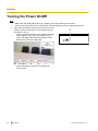
Turning the Power On/Off
Note
•
•
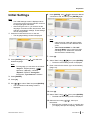
1
Make sure that peripheral devices (e.g., display, main video camera) are turned on.
When you turn the power on for the first time, the Initial Settings screen is displayed (Page 43).
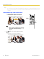
Press the Power button on the front of the unit or on the
remote control for more than 1 second. (Both can turn
the power on or off.)
• When the power is turned on, the Power LED starts
flashing green. Then, the Power LED becomes
green, the Status LED starts flashing blue slowly,
and the Home screen is displayed.
•
36
1
When the power is turned off, the Power LED
becomes red.
User Manual
Document Version 2014-11
Preparation
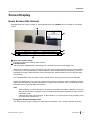
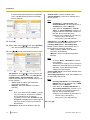
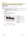
Screen Display
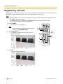
Home Screen (Idle Screen)
Displayed when the power is turned on. Also displayed when the [HOME] button is pressed on the remote
control.
A
B
C
F
D
E
Main Video Camera Image
Displays the video from the main video camera.
Unit Information
The information displayed differs depending on the selected connection mode (Page 116).
IP Mode: The connection mode, local site name, the SIP user name (if using a SIP server)/H.323 extension,
H.323 name (if using a gatekeeper), LAN1 IP address, LAN2 IP address (KX-VC1600 only), maximum
bandwidth, encryption status indication icons, and Static NAT status indication icons (if using the Static
NAT feature).
NAT Traversal Mode: The connection mode, local site name, Terminal ID, and maximum bandwidth.
IP/NAT Traversal Mode: The connection mode, local site name, Terminal ID, LAN1 IP address, LAN2 IP
address (KX-VC1600 only), maximum bandwidth, encryption status indication icons, and Static NAT status
indication icons (if using the Static NAT feature).
Note
•
•
When selecting a local site (Page 94), the selected local site’s information is displayed. The local
site’s set device name is displayed. The information displayed differs depending on the local site’s
connection mode.
If the local site name, SIP user name, H.323 extension, or H.323 name is too long to display, it will
be shortened and ended with "...".
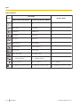
Encryption Status Indication Icons
The status of the encryption settings for SIP/H.323 is indicated by icons. The icon changes as follows:
Document Version 2014-11
User Manual
37
Preparation
Icon
Status of Settings
When using IP mode: "SIP" is set to "ON" and "Encryption (SIP)" is set to
"ON".
When using NAT Traversal mode or IP/NAT Traversal mode: "Encryption
(SIP)" is set to "ON".
When using IP mode: "SIP" is set to "ON" and "Encryption (SIP)" is set to
"OFF".
When using NAT Traversal mode or IP/NAT Traversal mode: "Encryption
(SIP)" is set to "OFF".
"H.323" is set to "ON" and "Encryption (H.323)" is set to "Best effort".
"H.323" is set to "ON" and "Encryption (H.323)" is set to "ON".
"H.323" is set to "ON" and "Encryption (H.323)" is set to "OFF".
Static NAT Status Indication Icon
Icon
Status of Settings
When using IP mode, "Static NAT" is set to "ON".
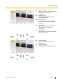
Group/Site
Displays the name/group name assigned to One-Touch Connection number 1 through 5. If the name is
too long to display, it will be shortened and ended with "...".
Remote Control ID
Displays the remote control ID of the unit when it is set (Page 107).
Shortcut key
Displays shortcut keys for accessing system settings.
Status Indication
The status of the unit is indicated by icons.
Icon
Status
Microphone is muted.
38
User Manual
Document Version 2014-11
Preparation
Icon
Status
Network, server (any kind), or peripheral connection error (no connection, device error,
etc.).
Note
•
If there are no connections, or there is a device error in other devices such as the
LAN cable, the icon will be displayed.
Note
•
If you set "Active Home Menu" to "OFF" in the administrator menu, you can hide BCDE
(Page 125). When hidden, you can unhide them again by pressing [FULL SCREEN] on the remote
control.
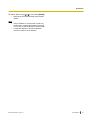
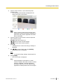
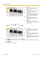
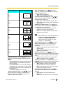
Menu Screen (Idle Screen)
Displayed when [MENU] is pressed on the remote control. Displays operations you can perform and settings
you can change.
A
B
C
Menu List
Displays the various functions you can use and settings available to change.
Guide
Displays operations you can perform with the remote control when performing features or changing
settings.
Administrator login
Press [Y] to display the administrator login screen for performing administrator settings.
Document Version 2014-11
User Manual
39
Preparation
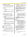
Video Conference Call Screen
A
B
C
D
F
G
E
Other party’s information
When using IP mode:
When registered in the contact list: The other party’s name/IP address is displayed.
When not registered in the contact list: The other party’s IP address, SIP URI (SIP user name@SIP domain
name), host name (e.g., hdvc.example.com), H.323 extension, H.323 name, MCU’s conference room
number@IP address, or MCU’s SIP user name@IP address is displayed. If the other party uses the same
SIP domain as you, only the SIP user name, and not the SIP URI, is displayed.
When using NAT Traversal Mode:
• When registered in the contact list: The other party’s name/connection number is displayed.
• When not registered in the contact list: The other party’s connection number is displayed.
Video Image
Displays the other party’s video, your own video, or video from the secondary video input such as a
computer display or a sub video camera.
Subscreen
Depending on the screen layout, your own video or the other party’s video is displayed here.
Duration
Displays the duration of the current video conference call.
Note
•
99h59m is displayed for the duration even if the length of the video conference call exceeds 100
hours.
Guide
Displays operations you can perform with the remote control.
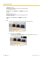
Network Status Indication
The number of antennas in the icon indicates differing levels of network congestion.
The icon changes as follows:
0 bars (
1 bar (
40
): The network is very congested or the bandwidth is insufficient at the connection point.
): The network is congested.
2 bars (
): The network is slightly congested.
3 bars (
): The network is not congested.
User Manual
Document Version 2014-11
Preparation
Note
•
•
•
If the icon shows only 0–1 bars continuously, contact your network administrator.
During multiple-party video conference calls, the icon is displayed on each site screen, but not on
your own image.
You can set whether to display the icon. This setting affects all displayed images (excluding your
own image) (Page 102). For example, if icon display has been enabled, the icon will be displayed
on the image of all other parties, but not on your own image. However, if icon display has been
disabled, the icon will not be displayed on any of the images. Regardless of icon display settings,
the icon is not displayed while the combined computer/video feed screen is being displayed.
Other Site’s Audio Indication (
)
Displayed on the Main Site when "Other Site's Audio" is set to "Mute" during a multiple-party video
conference call using the built-in MCU (Page 67, Page 91).
Dialling Indication (
)
Displayed when a call is incoming at another site, such as when a site is added during a call or when a call
is made (Page 60).
Status Indication
The status of the unit is indicated by icons (Page 38).
Note
•
*1
Pressing [FULL SCREEN] on the remote control will hide or unhide the other party’s information,
duration, network status indication*1, and guide displays.
If the network status indication has been set to not be displayed, pressing [FULL SCREEN] will not show the icon.
Document Version 2014-11
User Manual
41
Preparation
Entering characters
You can use the remote control to input letters and numbers.
• Note the following regarding entering the address of the other party.
– SIP user name/MCU’s conference room number: alphanumeric characters, symbols . = * + _ - $ ! ? /
( ) ' (up to 60 characters)
– H.323 name: alphanumeric characters, symbols . @ : ; = * + # _ - $ \ % ^ ! ? / ` ( ) [ ] {|} ' (up to 60
characters)
– SIP domain name: alphanumeric characters, symbols . - (up to 128 characters)
– H.323 extension: numeric characters, symbols * # (up to 20 characters)
• For host names in the format of user name@domain name, characters and the number of characters that
can be entered for user name and domain name are the same as for SIP user name and SIP domain name.
• The following characters can be used for input such as entering addresses in the contact list or directly
entering the address of the party to call.
– When using SIP: alphanumeric characters, symbols . @ : = * + _ - $ ! ? / ( ) ' (up to 189 characters)
– When using H.323: alphanumeric characters, symbols . @ : ; = * + # _ - $ \ % ^ ! ? / ` ( ) [ ] {|} '
(up to 189 characters)
When using SIP, the user name (portion before the @ mark) can be up to 60 characters, and the domain
name (portion after the @ mark) can be up to 128 characters.
• Enter values that comply with the corresponding standard. For details, contact your network administrator.
42
User Manual
Document Version 2014-11
Preparation
6. Press [ENTER], use [
Initial Settings
][ ] to select the desired
connection mode, and then press [ENTER] again.
Note
•
•
The Initial Settings screen is displayed when
you turn the power on for the first time. It will not
be displayed again afterwards.
After turning the unit on, you need to set the
language, connection mode, device name, date
and time, and network settings. These settings
can be changed later.
1. Press the Power button to turn on the unit.
• The language settings screen is displayed.
Note
•
•
Calls cannot be made with other parties
whose connection mode is different from
yours.
"NAT Traversal Mode" or "IP / NAT
Traversal Mode" can be used only after
activating KX-VC Series NAT Traversal
Service with an activation key.
7. Press [G].
2. Press [ENTER] and use [
][
] to select the
desired language.
Note
•
The language you can select is as follows:
":
"English": English (default), "
Japanese, " ㅔԧЁ᭛ ": Chinese,
"Español": Spanish, "Português":
Portuguese, "Русскийязык": Russian
8. Select "Yes" using [ ][ ], then press [ENTER].
• The device name setting screen is displayed.
9. Enter a name for the device (up to 24 characters)
(Page 141).
3. Press [ENTER].
4. Press [G].
5. Use [ ][ ] to select "Yes" and press [ENTER].
• The connection mode setting screen is
displayed.
10. Press [G].
11. Select "Yes" using [ ][ ], then press [ENTER].
• The date and time setting screen is displayed.
12. Select the item using [
][ ] , then input
information.
• Enter the year (4 digits), month (1–2 digits), day
(1–2 digits), time (24 hour display), and select
Document Version 2014-11
User Manual
43
Preparation
the date format (Month/Day/Year, Day/Month/
Year, Year/Month/Day) and the hour display
format (12h/24h).
"Subnet mask": Enter the subnet mask.
"Default Gateway": Enter the IP address of the
default gateway.
Note
•
•
13. Press [G].
14. Select "Yes" using [ ][ ], then press [ENTER].
• The network settings screen is displayed.
15. Use [
][
] to select the following items for input:
"IP Address", "Subnet mask", and
"Default Gateway" can be entered only if
"IP Address" is set to "Manual".
If the value for "IP Address", "Subnet
mask", or "Default Gateway" contains 1 or
2 digits numbers, enter these numbers as
they are. Do not enter like [.001].
Example: The IP address is [192.168.0.1].
– Correct entry: [192.168.0.1]
– Wrong entry: [192.168.000.001]
"DNS Server": Use [ ][ ] to select whether the
IP address information for the DNS servers
("Primary DNS Server", "Secondary DNS
Server") will be obtained automatically from a
DHCP server or will be set manually.
– "Auto" (default): Obtain the IP address
information automatically.
– "Manual": Set the IP address information
manually.
Note
•
"IP Address": Use [ ][ ] to select whether the
IP address information for this unit ("IP Address",
"Subnet mask", "Default Gateway") will be
obtained automatically from a DHCP server or will
be set manually.
– "Auto" (default): Obtain the IP address
information automatically.
– "Manual": Set the IP address information
manually.
Note
•
Even if you have selected "Auto", you still
may not be able to acquire an IP address
due to problems such as network
congestion. In this case, "Address is not
assigned" is displayed in the upper right of
the Home screen. Contact your network
administrator.
"IP Address": Enter the IP address of the unit.
44
User Manual
To select "Auto", "IP Address" must be
set to "Auto".
• The DNS server must be set to use KX-VC
Series NAT Traversal Service, to check for
upgrades, and to download the latest
software from the network.
"Primary DNS Server": Enter the IP address of the
primary DNS server.
"Secondary DNS Server": Enter the IP address of
the secondary DNS server.
Note
•
•
"Primary DNS Server" and "Secondary
DNS Server" can be entered only if "DNS
Server" is set to "Manual".
If the value for "Primary DNS Server" or
"Secondary DNS Server" contains 1 or 2
digits numbers, enter these numbers as
they are. Do not enter like [.001].
Example: The IP address is [192.168.0.1].
– Correct entry: [192.168.0.1]
– Wrong entry: [192.168.000.001]
16. Press [G].
Document Version 2014-11
Preparation
17. Select "Yes" using [ ][ ], then press [ENTER].
• Settings become effective after the automatic
restart.
Note
•
•
If the IP address or subnet mask contains an
invalid value, a message will appear requiring
you to enter a valid IP address or subnet mask.
A multicast address or broadcast address
cannot be used for the IP address.
Document Version 2014-11
User Manual
45
Starting a Video Conference
S
t
a
r
Making a Video Conference Call
t
You can make a video conference call using one of the following methods.
i
n
Note
g
•
•
a
V
Make sure that peripheral devices (e.g., display, main video camera) are turned on.
If a called party does not answer a video conference call within approximately 60 seconds, the call will
be terminated automatically.
Only 2-party video conference calls can be made using the incoming call history.
The number of bars in the antenna icon will be 0 to indicate communication bandwidth that is lower
than 256 kbps per site. In such cases, the image and voice quality may deteriorate.
Video conference calls cannot be made if the call type programmed in the contact list (SIP or H.323)
has been set to "OFF" on the call type settings screen.
If a video conference call is made using a profile with an entry restriction, and you want to add a party
to that call, you cannot call the party by entering an address directly or by using the call history.
If a video conference call is received during another video conference call, a dialogue box is displayed
to confirm whether to answer the incoming video conference call.
Use [ ][ ] to select "Yes" or "No" and press [ENTER].
• Select "Yes" to answer the video conference call.
• Select "No" to stop receiving the incoming video conference call and continue your current video
conference call.
i
•
•
d
e
o
•
C
o
•
n
f
•
e
r
e
n
c
e
Calling Using One-Touch Connection Numbers From the Home
Screen
Note
•
To call using one-touch connection numbers, you need to set them in advance (Page 104).
1
Press [HOME].
• The Home screen is displayed.
2
With the dial keys, enter a One-Touch Connection number
(1 to 5).
• The information registered in the selected One-Touch
Connection number is displayed.
1
3
4
2
3
4
Press [START] to start the call.
• You can also start the call pressing [ENTER].
When you want to end the call, press [END].
The Home screen is displayed.
•
46
User Manual
Document Version 2014-11
Starting a Video Conference
Calling from the Contact List (2-party Conference)
Note
•
•
To make a video conference call from the contact list, you must first register contacts in the contact list
(Page 88).
If "IP Address" is set to "Auto" on the network settings screen (Page 99), the unit’s IP address will
be automatically obtained using a DHCP server, and therefore may change to a different IP address
from the one registered in the other party’s contact list. In such cases, when the other party tries to call
you by selecting a registered IP address from their contact list, the call will not be connected. For details,
contact your network administrator.
1
Press [MENU].
• The Menu screen is displayed.
2
Select "Contact List" using [ ][ ] and press
[ENTER].
• The contact list screen is displayed. The entries are
grouped in the index tabs and displayed in
alphabetical order of "Site".
1
2, 3
4
5
Note
•
If you press [Y], entries are displayed in the
speed dial number order.
Document Version 2014-11
User Manual
47
Starting a Video Conference
3
Select the entry you want to call using [ ][ ].
• You can switch the index tab back and forth using
[ ][ ]. (Index tabs in which no entries exist will be
skipped.)
• Press a numeric button on the remote control to
switch to the index tab assigned to that button, as
shown below.
Numeric button
Index Tab
1
–
2
ABC
3
DEF
4
GHI
5
JKL
6
MNO
7
PQRS
8
TUV
9
WXYZ
0
0-9
-&!/
#
–
Note
•
4
5
If the display is sorted by speed dial number in
step 2, you can click a speed dial number (1
through 600) to select it.
Press [START] to start the call.
When you want to end the call, press [END].
The Home screen is displayed.
•
48
User Manual
Document Version 2014-11
Starting a Video Conference
Calling Using Profile (Multiple-party Video Conference Calls)
When making multiple-party video conference calls from the Menu screen, you can make a call using one of
20 profiles (1 to 20).
Note
•
To call using a profile, you need to have a profile programmed in profile settings in advance
(Page 90).
1
Press [MENU].
• The Menu screen is displayed.
2
Select "Profile" using [ ][ ] and press [ENTER].
• The profile list screen is displayed.
1
2, 3
4
3
Select the profile you want to use to make a call using
[ ][ ].
4
Press [START] to start the call.
5
When you want to end the call, press [END].
• For ending a multiple-party video conference call,
refer to "Disconnecting Parties During Video
Conference Call (Page 62)".
5
Note
•
You can make a video conference call by changing
the party of the selected profile before starting the call
by pressing [START]. Be aware that the selected
connection destination will not be saved.
Document Version 2014-11
User Manual
49
Starting a Video Conference
1. Press [B].
• The profile settings screen is displayed.
2. Select "Site" using [ ][ ], then press [ENTER].
• The screen for selecting the party you want to
call from the profile is displayed.
][ ], then press
[ENTER].
• Selecting an item will add or remove the " "
mark for the item in the selection column. The
contacts with a " " mark will be called.
4. Press [START] to start the call.
• A dialogue box to confirm the start of a call is
displayed.
5. Use [ ][ ] to select "Yes" and press [ENTER].
3. Select the party using [
50
User Manual
Document Version 2014-11
Starting a Video Conference
Calling by Entering an Address Directly
When using IP mode, you can make a video conference call by entering the IP address (or host name), SIP
URI (or SIP user name), H.323 extension, H.323 name, or MCU’s conference room number@IP address.
When using NAT Traversal mode, you can make a call by entering the connection number.
1
Press [MENU].
• The Menu screen is displayed.
2
Select "Manual Dial" using [ ][ ] and press
[ENTER].
• The manual dial screen is displayed.
1
2-5,
7-8
9
10
6
Note
•
You can display the manual dial screen by
pressing [START] in the Home screen instead
of performing steps 1 and 2.
3
Use [ ][ ] to select the connection mode you want to
input ("Connection mode 1" to "Connection mode
9") and press [ENTER].
4
Use [ ][ ] to select the connection mode ("IP Mode
(SIP)", "IP Mode (H.323)", "NAT Traversal Mode").
5
Use [
6
When using IP mode, enter the IP address (or host
name), SIP URI (or SIP user name), H.323 extension,
H.323 name, or MCU’s conference room number@IP
address. When using NAT Traversal mode, enter the
connection number (7 digits).
][
] to select the site ("Site 1" to "Site 9").
Note
•
•
When starting multiple-party video conference
calls, repeat steps 3-6.
When calling more than 4 parties, press [R] to
display the next page.
7
Use [ ][ ] to select "Outgoing Bandwidth / Site"
and press [ENTER] on the first page.
8
Use [ ][ ] to select the outgoing bandwidth/site to be
used ("Not Specified", "256 kbps"–"18 Mbps"). (The
default maximum selectable value: "9.0 Mbps")
Document Version 2014-11
User Manual
51
Starting a Video Conference
9
Press [START] to start the call.
• You can also start the call by pressing [ENTER].
10
When you want to end the call, press [END].
The Home screen is displayed.
•
Note
•
•
•
•
•
•
•
•
•
When using the KX-VC1300, you can have video conference calls with a maximum of 3 parties
simultaneously. When you are using the KX-VC1600, the maximum is 5 simultaneous parties, and if
you have the activation key card (KX-VCS304) for enhanced features, you can make multiple-party
video conference calls with a maximum of 9 parties.
If the IP address contains 1 or 2 digit numbers, enter these numbers as they are. Do not enter like [.
001].
Example: The IP address is [192.168.0.1].
– Correct entry: [192.168.0.1]
– Wrong entry: [192.168.000.001]
To initiate a video conference call by entering a SIP URI (SIP user name@SIP domain name), you
must set "SIP Server" to "ON" and specify "SIP Server Address", "SIP Username", and "SIP
Domain Name". Also, specify "Digest Authentication", "Authentication ID", and "Authentication
Password" as necessary (Page 118). For details, contact your network administrator.
When making a video conference call within your own SIP domain, you can make the call by entering
the other party’s SIP user name. When the other party is not within your SIP domain, you must also
include their SIP domain name in addition to their SIP user name.
When a SIP domain name is not specified, your own SIP domain name is automatically appended to
the address and the call is made. Be careful as this may result in calling the wrong party.
See Page 42 for details about the characters that can be input for address entry.
Enter a standards-compliant value. For details, contact your network administrator.
To initiate a video conference call by entering an MCU’s conference room number@IP address, "SIP
Server" and "Gatekeeper" must be set to "OFF" (Page 118, Page 120).
If the other party is using the KX-VC300/KX-VC600 with a software version older than 3.00 (not
including 3.00), you cannot make a video conference call using H.323. You must set "SIP" to "ON"
on the call type settings screen (Page 118).
Items that have been set to "No" on the call type settings screen (Page 118) cannot be set in the
connection mode settings.
You can refer to the contact list or call history when entering a destination by following the procedure
below from the manual dial screen (you cannot enter a destination using the profile):
When using IP mode: the IP address (or host name), SIP URI (or SIP user name), H.323 extension,
H.323 name, or MCU’s conference room number@IP address
When using NAT Traversal mode: the connection number
1. Press [G].
• A dialogue box to select either the contact list or call history is displayed.
2. Use [ ][ ] to select the contact list or call history, and then press [ENTER].
3. Use [ ][ ] to select the contact you want to refer to.
• For the contact list, you can use [ ][ ] or the numeric buttons of the remote control to select
the displayed tab (Page 48).
For the call history, press [G] to switch between the incoming call history and the outgoing call
history.
4. Press [ENTER].
When using H.323, you can also call by entering the other party’s IP address (or host name) %H.323
extension (or H.323 name).
•
•
52
User Manual
Document Version 2014-11
Starting a Video Conference
Calling from the Call History
You can make a video conference call from the call history. The call history is divided into outgoing and incoming
calls. The last 50 video conference calls made and received are stored in the outgoing and incoming call history.
Information such as the contact name, group name, address information*1, the date and time, the duration of
the call, the result of the call, and the connection mode is displayed for each call on the outgoing call history
screen and incoming call history screen. If the address of an entry in the call history is deleted from or edited
in the contact list, the contact name in the call history entry will be replaced by the address information.
*1
Address information is as follows.
IP address/host name/SIP URI/H.323 extension/H.323 name/MCU’s conference room number@IP address/MCU’s SIP user
name@IP address/connection number. (When using NAT Traversal mode, the connection number is displayed.)
Note
•
If the other party uses the same SIP domain name as you, only the SIP user name, and not the SIP
URI (SIP user name@SIP domain name) will be displayed in the call history.
Outgoing Call History:
• For video conference calls made using the contact list, the contact name is displayed. For video conference
calls made by entering the IP address (or host name)/SIP URI/H.323 extension/H.323 name/MCU’s
conference room number@IP address/connection number directly (Page 51), that information is displayed
instead of the contact name. (That information is displayed even if a matching entry exists in the contact
list.)
• Even when a profile is used to make a video conference call, the call will appear in the outgoing call history.
You can then make a video conference call with a profile from the outgoing call history.
• If consecutive video conference calls are made to the same destination, only the latest call will appear in
the outgoing call history.
Incoming Call History:
• If the calling party’s IP address/SIP URI/H.323 extension/H.323 name/MCU’s conference room
number@IP address/connection number is registered in the contact list, the contact name/group name is
displayed. Otherwise, the IP address (or host name)/SIP URI/H.323 extension/H.323 name/MCU’s
conference room number@IP address/MCU’s SIP user name@IP address/connection number is
displayed.
• Depending on the type of MCU, a video conference call may be received from the MCU’s SIP user
name@IP address rather than the MCU’s conference room number@IP address. In that case, you directly
cannot call the MCU’s conference room from this incoming call history.
• If consecutive unanswered video conference calls are received from the same party, only the latest call
will appear in the incoming call history.
• When connecting to a non-Panasonic video conference system, you may not be able to initiate video
conference calls with SIP URIs (or SIP user names)/H.323 extension/H.323 name in the incoming call
history. In this case, contact your network administrator.
Document Version 2014-11
User Manual
53
Starting a Video Conference
1
Press [MENU].
• The Menu screen is displayed.
2
Select "Call History" using [ ][ ] and press
[ENTER].
• The outgoing call history screen is displayed.
1
2, 3
4, 5
6
Note
•
•
•
•
•
54
User Manual
The result of the video conference call is
displayed in the "Call result" column as follows:
: The video conference call was
–
established.
–
: The video conference call was not
established.
: Calling using a profile
–
To move to the incoming call history screen,
press [G]. You can switch between the outgoing
call history screen and the incoming call history
screen by pressing [G].
When calling using a profile, the Profile ID (PID)
is displayed.
In the incoming call history, if a party is not
registered in your contact list, the address
information received from the party is displayed.
In the outgoing call history, if a party is registered
in your contact list, the contact name is
displayed. However, when calling by entering an
IP address (or host name), SIP URI (or SIP user
name), H.323 extension, H.323 name, or MCU’s
conference room number@IP address/
connection number (Page 51), even if the party
is registered in your contact list, the entered
information is displayed instead of the contact
name.
Document Version 2014-11
Starting a Video Conference
•
•
3
When a contact in the incoming call history is
newly added to your contact list, the incoming call
history will be updated to display the contact’s
information from the contact list.
When a party that is not registered in your contact
list is selected, if you press [B], the contact list
registration screen will be displayed and a new
contact can be registered (Page 90). Also, you
may not be able to register a SIP URI (or SIP user
name), H.323 extension, or H.323 name from the
incoming call history to the contact list for
reasons such as non-compliance with the
relevant standards. In this case, contact your
network administrator.
Select the party you want to call using [
][
].
Note
•
If you press [ENTER], the call history details
screen is displayed.
•
When not selecting a local site (Page 94), the
values of the basic settings are displayed for
"Local site name".
"Bandwidth" displays the mediated bandwidth
for connected sites.
Depending on the other party, "Device type"
may be blank.
•
•
4
Press [START].
• The manual dial screen is displayed.
Note
•
5
6
You can change the number of sites called
or edit the other party’s address.
Press [START] to start the call.
When you want to end the call, press [END].
The Home screen is displayed.
•
Document Version 2014-11
User Manual
55
Starting a Video Conference
Answering a Video Conference Call
Depending on your setting, you can either respond to a request to participate in a video conference call
manually (manual answer) or automatically (automatic answer) (Page 101).
Note
•
•
Make sure that peripheral devices (e.g., display, main video camera) are turned on.
For sites operating as "Sub Sites" in multiple-party video conference calls using the Main Site’s built-in
MCU, for each Sub Site, set "More than one incoming call" to "OFF" in "Call set up". With this
setting, calls cannot be received during a video conference call.
When Manual Answer is Set
When a video conference call is incoming there will be an incoming call ring, and a dialogue box is displayed.
When the caller is registered in the contact list, the caller’s site
is displayed.
When the caller is not registered, the caller’s IP address,
connection number or other caller information that is received
is displayed.
Note
•
If the other party uses the same SIP domain name as you, only the SIP user name, and not the SIP
URI (SIP user name@SIP domain name) is displayed.
If the caller’s group/site name, host name, SIP URI (or SIP user name), H.323 extension, or H.323
name is too long to display, it will be shortened and ended with "...".
•
Operation
1
Press [START].
The video conference begins.
You can also answer the video
conference call by pressing [ENTER].
•
•
1
56
User Manual
Document Version 2014-11
Starting a Video Conference
Note
•
•
If you do not answer a video conference call within approximately 60 seconds, the call will be terminated
automatically.
If a video conference call is received while making a video conference call, a dialogue box to confirm
if you answer a video conference call is displayed (only when "More than one incoming call" is set
to "ON" in "Call set up").
Use [ ][ ] to select "Yes" or "No" and press [ENTER].
– When "Yes" is selected, you can answer a video conference call.
– When "No" is selected, you can stop receiving a video conference call and continue making a
video conference call.
When Automatic Answer is Set
When a video conference call is incoming the call will be automatically answered after one ring, and
transmission then begins.
Document Version 2014-11
User Manual
57
Starting a Video Conference
Connecting to an MCU
Connecting to an MCU allows you to have a video conference call with 10 or more parties.
Intranet
MCU
Note
•
•
•
•
•
•
•
•
•
58
MCUs you want to connect to must meet the following criteria. Confirm the settings of the MCU.
– Supports SIP or H.323 communication
– Supports communication with the H.264 Baseline Profile and H.264 High Profile
– Supports communication with the G.711, G.722, G.722.1, and G.722.1 Annex C voice codecs
For details about the types of MCUs you can connect to, contact your dealer.
Video conference calls to an MCU through a SIP server using a SIP URI are not guaranteed. IP
addresses must be specified to make calls.
The connection specifications (e.g., resolution) and available functions (e.g., content sharing) differ
depending on the MCU you connect to. For details, contact your dealer.
The procedure for connecting to an MCU differs depending on the MCU. For details, contact your
dealer.
Audio sent to the other party is monaural.
While you are displaying a sub video camera’s image, you cannot send a still image from the sub video
camera.
Encrypted communication may not be supported. In such cases, connect to an MCU over an intranet
or via a VPN. For details, contact your dealer.
The maximum bandwidth specified in the settings at the beginning of the connection is applied for the
duration of the connection to an MCU. Depending on the network conditions, you must specify an
appropriate bandwidth setting (Page 101).
User Manual
Document Version 2014-11
Starting a Video Conference
Operating an MCU Remotely using Tone Signals
When connecting to an MCU, you can send tone signals by pressing buttons (0–9, #, or ) on the remote
control. Doing so allows you to operate (e.g., change the screen layout) the MCU remotely.
Note
•
•
•
•
1
Features and operations that can be performed
remotely will vary depending on the MCU.
If the MCU you are connecting to does not support
tone signals, an error message is displayed.
If the other party sends tone signals to you, sound
may be interrupted or a ringing noise may occur.
You can operate the other party’s device using tone
signals with the KX-VC1600/KX-VC1300/
HDVC-MPCS.
1
Enter a tone signal (0–9, #, or ).
The input field (A) is displayed.
•
A
Note
•
•
•
•
The input field can only contain up to 16
characters. If you input 17 characters, the first
character input will not be displayed in the input
field but all tone signals will be sent.
The input field is not displayed until a tone signal
is entered.
If a tone signal is not entered for about 3
seconds, the input field disappears.
If you enter further tone signals after the input
field has disappeared, the tone signals entered
the previous time are also displayed.
Document Version 2014-11
User Manual
59
During Video Conference Calls
D
u
r
i
n
g
Adding Parties to an Existing Video Conference Call
(Except Sub Sites)
V
A site in a 2-party video conference call or the Main Site can use the following operations to add parties to an
existing call.
i
d
e
1. Press [MENU].
• The communication menu screen is displayed.
2. Use [ ][ ] to select "Make a call" and press [ENTER].
• A dialogue box to select a dialling method is displayed.
o
C
o
n
f
e
r
e
n
c
e
C
a
l
l
s
Note
•
•
3. Use [
For sites that are in a video conference call that was made using methods other than profile calling,
the dialogue box is not displayed, and the manual dial screen is displayed instead.
For sites that are in a video conference call that was made using profile calling with entry restriction
set to "ON" in the profile settings, the dialogue box is not displayed, and the profile used to make
the call is selected.
][
] to select the dialling method ("Profile" or "Manual Dial").
When selecting profile:
• The profile setting/selection screen is displayed.
1. Select the profile of the other party whom you want to add using [
• " " is displayed in the selection field.
60
User Manual
][
] and press [ENTER].
Document Version 2014-11
During Video Conference Calls
When selecting manual dial:
• The manual dial screen is displayed.
1. Programme the information of the other party whom you want to add using [
][
].
Note
•
You can refer to the contact list or call history when entering the other party’s information.
Press [G].
• A dialogue box to select either the contact list or call history is displayed.
Use [ ][ ] to select the contact list or call history, and then press [ENTER].
Use [ ][ ] to select the contact you want to refer to.
• For the contact list, you can use [ ][ ] or the numeric buttons of the remote control to
select the displayed tab (Page 48).
• For the call history, press [G] to switch between the incoming call history and the outgoing
call history.
Press [ENTER].
4. Press [START].
Note
•
If your own site becomes a Sub Site, do not try to add additional sites to a video conference call.
Document Version 2014-11
User Manual
61
During Video Conference Calls
Disconnecting Parties During Video Conference Call
You can disconnect parties during a video conference call.
Disconnecting a 2-party conference
1. Press [END].
• The video conference call is disconnected.
Disconnecting a multi-party conference (Main Site only)
1. Press [END].
• A dialogue box to select the party you want to disconnect is displayed.
Note
•
In step 1, pressing [MENU], using [
will still display the dialogue box.
][
] to select "Disconnect", and then pressing [ENTER]
2. Select the party whom you want to disconnect using [
• The selected party is disconnected.
][
] and press [ENTER].
Disconnecting a multi-party conference (Sub Site only)
1. Press [END].
• The video conference call is disconnected.
62
User Manual
Document Version 2014-11
During Video Conference Calls
Changing the Screen Layout during a Video
Conference Call
You can change the layout of the screen during a video conference call.
Note
•
•
1
Display patterns differ depending on the number of displays, the number of parties, whether to share
contents or not, whether it is Main Site or Sub Site, and whether the communication is single stream
or dual stream.
The default screen layout during a video conference call can be changed by the settings of "Default
Screen Layout" of "Video Output" (Page 122).
Press [LAYOUT].
• The screen will cycle through the available layouts
each time you press [LAYOUT].
– Layout 1: The other party’s image is displayed
full screen.
– Layout 2: The other party’s image is displayed
full screen, and your own image is displayed in
the upper right subscreen (PwithP).
– Layout 3: The other party’s image and your own
image are displayed (Side by side).
– Layout 4: Your own image is displayed full
screen.
1
Example: 1 display, 2-party video conference, without content sharing, Main Site, Single stream
communication
[LAYOUT]
The other party
The other
party
[LAYOUT]
[LAYOUT]
You
The
other
party
You
You
[LAYOUT]
Changing the Other Party’s Screen Display Layout
During a video conference call, you can change the other party’s screen display layout. The numbers in the
layout configurations indicate each site’s image display priority. (Hereafter, the display with priority 1 will be
described as the "main display".)
Main Site operations
1. Press [MENU].
• The communication menu screen is displayed.
Document Version 2014-11
User Manual
63
During Video Conference Calls
2. Use [ ][ ] to select "Screen mode set." and press [ENTER].
• A layout settings dialogue box is displayed.
3. Use [ ][ ] to select a layout to set, and press [ENTER].
– "Auto": Automatically changes the layout depending on the number of parties joining a video
conference call.
– "CP1" to "CP10": Changes to the selected layout.
Layout according to the number of sites when "Auto" is selected
Number of Sites
Layout Number
2
CP1
3–4
CP4
5–6
CP6
7–8
CP8
9–10
CP10
Layout patterns that can be selected during a video conference call
Layout Number
Layout Configuration
1
CP1
CP2
CP4
64
User Manual
1
2
1
2
3
4
Document Version 2014-11
During Video Conference Calls
Layout Number
Layout Configuration
2
3
6
1
CP6
4
5
2
3
4
8
1
CP8
5
6
1
CP10
3
7
7
2
4
8
5 6
9 10
Operation of Sub Sites
During a video conference call, you can use remote control operations to change the screen display layout
from a Sub Site.
Remote Control Operation and Layout for Sub Sites
Numerical Keypad
Layout Number
*21
CP1
*22
CP2
*24
CP4
*26
CP6
*28
CP8
*20
CP10
Note
•
•
•
If "DTMF layout change" in "MCU Settings" is set to "OFF", operations cannot be performed from
a Sub Site (Page 103).
When the layout is changed from a Sub Site, all sites’ layouts are also changed.
When the layout of the Main Site automatically changes (when "Screen Layout" of "MCU
Settings" is set to "Auto" [Page 102], or when "Screen mode set." is set to "Auto" on the
communication menu screen [Page 64]), operations cannot be made from a Sub Site.
Document Version 2014-11
User Manual
65
During Video Conference Calls
Changing the Setting of the Main Display (Main Site
only)
The settings of the site displayed as the main site during a call can be changed.
1. Press [MENU].
• The communication menu screen is displayed.
2. Use [ ][ ] to select "Main Position set." and press [ENTER].
• The main display settings dialogue box is displayed.
3. Use [ ][ ][ ][ ] to select a switching method.
– "Voice Activation 1": The party (caller) with the loudest volume during a call will be automatically set
as the main display.
– "Voice Activation 2": Your own site’s image is fixed as the main display, and the party (caller) with
the loudest volume during a call will be set to display priority 2.
– "Local Site": Displays your own site.
– "Site 1" to "Site 9": Displays the selected site as the main display.
Note
•
66
When sharing a computer’s screen or sub camera image on one screen, the shared screen
automatically becomes the main display (for the receiving end only during single stream
communication).
User Manual
Document Version 2014-11
During Video Conference Calls
Changing the Site Name Display (Main Site only)
The setting of whether site names are displayed during a video conference call can be changed.
1. Press [MENU].
• The communication menu screen is displayed.
2. Use [ ][ ] to select "Site name display" and press [ENTER].
• The site name display setting dialogue box is displayed.
3. Use [
][
] to select whether to display a site name ("ON", "OFF"), and press [ENTER].
Changing the Audio Settings for Other Parties (Main
Site only)
You can set whether the audio of the other party during a video conference call will be combined with the audio
of the Main Site, or if it will be muted.
1. Press [MENU].
• The communication menu screen is displayed.
2. Use [ ][ ] to select "Other Site's Audio" and press [ENTER].
• The other party’s audio setting dialogue box is displayed.
3. Use [ ][ ] to select "Mix" or "Mute" and press [ENTER].
– "Mix" (default): Audio is output that combines the audio of the other party with that from the Main Site.
– "Mute": Mutes the audio of the other party. Only the audio of the Main Site is output.
Document Version 2014-11
User Manual
67
During Video Conference Calls
Adjusting the Volume
You can adjust the volume during a video conference call.
1
Press [VOLUME (+/–)].
• The volume level bar is displayed at the bottom of
the screen.
2
Adjust the volume using [VOLUME (+/–)].
• Pressing [+] will increase the volume of the other
party’s voice.
• Pressing [–] will decrease the volume of the other
party’s voice.
After about 3 seconds, the volume level bar disappears.
1, 2
Note
•
•
•
68
You can set the volume level of a video conference call before starting the call (Page 105).
After ending a video conference call, the volume level returns to the volume level set before starting
the call.
You cannot adjust the display’s volume.
User Manual
Document Version 2014-11
During Video Conference Calls
Muting the Microphone
During a video conference call, you can mute the microphone so that your voice cannot be heard by the other
party. You will be able to hear the other party’s voice, but they will not be able to hear you.
Note
•
You can set the microphone(s) to be mute at the start of a received video conference call (Page 102).
Muting the Microphone (Operation with the Remote Control)
1
Press [MIC MUTE].
• An icon appears in the status display area of the
screen (Page 37), and the LED light on the Boundary
Microphone becomes red. Make sure the colour of
the LED changes.
• Pressing [MIC MUTE] again will unmute the
microphone. The LED light on the Boundary
Microphone becomes green. Make sure the colour
of the LED changes.
1
Document Version 2014-11
User Manual
69
During Video Conference Calls
Muting the Microphone (Operation with the Boundary Microphone)
1
Press the MIC Mute button.
• An icon appears in the status display area of
the screen (Page 37), and the LED light on the
Boundary Microphone becomes red. Make
sure the colour of the LED changes.
• Pressing the MIC Mute button again will
unmute the microphone. The LED light on the
Boundary Microphone becomes green. Make
sure the colour of the LED changes.
1
Digital Boundary
Microphone
1
Analogue Boundary
Microphone
Note
•
•
•
70
User Manual
When multiple Digital Boundary
Microphones are connected, pressing
the MIC Mute button of one Digital
Boundary Microphone will mute all
Digital Boundary Microphones.
When using Digital Boundary
Microphones and an Analogue
Boundary Microphone together,
pressing the MIC Mute button on one
Boundary Microphone will mute all
Boundary Microphones.
If a headset is connected, the MIC Mute
button on a Boundary Microphone will
not work.
Document Version 2014-11
During Video Conference Calls
Reducing Microphone Noise
You can reduce the amount of ambient noise picked up by the microphone (shuffling of papers, etc.) during a
video conference call. When noise reduction is in effect, the volume level of voices may also be reduced.
1
Press [Y].
• "Whisper Mode [ON]" is displayed, and noise
reduction is enabled.
1
•
Pressing [Y] again will display "Whisper Mode
[OFF]", and noise reduction is disabled.
Note
•
•
•
Noise reduction is available only when Digital
Boundary Microphones are connected.
You can set whether to enable noise reduction
for a video conference call before starting the
call (Page 102).
After a video conference call is finished, the
noise reduction setting returns to the value set
before starting the call.
Document Version 2014-11
User Manual
71
During Video Conference Calls
Displaying a Computer’s Screen and the Sub Video
Camera’s Image
When a computer or sub video camera is connected to the unit, you can display the computer’s screen or the
sub video camera’s image on your display and to other parties. This is convenient when explaining something
on the computer’s screen or the sub video camera’s image while showing them to others, for example.
Main video
camera
Main video
camera
Sub video
camera
Computer
Router
Internet
Sub video
camera
Computer
Router
Note
•
The computer screen resolutions supported by the unit are VGA (640 ´ 480), SVGA (800 ´ 600), XGA
(1024 ´ 768), HD (1280 ´ 720), and WXGA (1280 ´ 768, 1280 ´ 800), SXGA (1280 ´ 1024), UXGA
(1600 ´ 1200), WSXGA+ (1680 ´ 1050), Full-HD (1920 ´ 1080).
1. Press [PC] or [CAMERA SUB] during a video conference call.
For dual stream communication:
• You can send the image of your video camera and the image of your computer’s screen or a sub video
camera at the same time to the other party. You can view the other party and check shared data at the
same time.
Note
•
If dual stream communication is disabled in the communication settings (Page 101), or if a device
that does not support dual stream communication is connected, the screen switching method will
be used.
When using the screen switching method (hereafter referred to as "single stream communication"):
• Switches the display from the image of the main video camera to that of the computer’s screen or the
image of the sub camera. The same image is also shown on the other party’s display.
2. Press [CAMERA MAIN] to return to the image of the main video camera.
72
User Manual
Document Version 2014-11
During Video Conference Calls
Example: single stream communication (2 screens
used, 4-party video conference, at the Main Site)
Example: dual stream communication (2 screens
used, 4-party video conference, at the Main Site)
Without contents
sharing
Without contents
sharing
HDMI1
Site 1
Site 2
Site 3
Site 4
[CAMERA MAIN]
HDMI2
Your
Own Site
[PC]/
[CAMERA SUB]
With contents
sharing
Other Video
Sources
HDMI1
Site 1
Site 2
Site 3
Site 4
[CAMERA MAIN]
Other Video
Sources
Other Video
Sources
[PC]/
[CAMERA SUB]
Other Video
Sources
Other Video
Sources
[LAYOUT]
Site 1
Site 2
Site 3
Site 4
[LAYOUT]
Site 1
Site 2
Site 3
Site 4
Other Video
Sources
[LAYOUT]
[LAYOUT]
Other Video
Sources
Your
Own Site
With contents
sharing
[LAYOUT]
Other Video
Sources
HDMI2
Other Video
Sources
Other Video
Sources
[LAYOUT]
*Sites 1 through 4 are your own site or another party’s site.
Document Version 2014-11
User Manual
73
During Video Conference Calls
Note
•
•
•
•
74
Pressing [LAYOUT] in succession will
switch the displays of the 2 monitors in
different combinations of the contents image
display, the contents image combined with
the camera image, and the camera image
display.
For single stream communication:
– During a 2-party call, depending on the
screen layout state of the other party, the
display of the other party may not show
the same screen as yours. In such
cases, press [CAMERA MAIN] to cancel
contents sharing, or instruct the other
party to change their screen layout to
one that displays your screen.
For dual stream communication:
– While sharing the contents of a
computer’s screen or the sub camera
image, the other party can also share
their contents. Note that in this case, the
images for the contents of all sites will
change to the last shared image.
While the Home screen (idle screen) is
displayed, pressing [PC] or [CAMERA
SUB] will display the contents of the
computer’s screen or the sub camera’s
image. When displaying the computer’s
screen or the image of the sub camera, the
system will not enter screen standby mode.
To return to the Home screen, press
[CAMERA MAIN].
User Manual
Document Version 2014-11
Controlling a Video Camera
C
o
n
t
Controlling a Video Camera
r
o
l
l
If a PTZ (pan, tilt, zoom) camera or a FIX camera is connected to your unit or the other party’s unit, you can
control the pan (side-to-side movement), the tilt (up-down movement), and the zoom of the video camera during
a video conference call. You can perform this operation with the main video camera or a sub video camera.
i
n
Note
•
g
a
V
•
•
i
d
e
•
o
C
•
a
m
•
e
r
a
•
•
•
In this manual, "PTZ camera" indicates a video camera whose moving parts will rotate when the
direction of the video camera is changed. "FIX camera" indicates a video camera that has no moving
parts and does not rotate.
For details about compatible video camera models, contact your dealer.
The features that can be used may be limited depending on your video camera model.
(e.g., A video camera with only a zoom feature)
When the other party is using a non-Panasonic video conference system, some operations may not
be available, or unintended operations may occur.
The setting "Direct Cam Ctrl on Home Screen" can be used to disable the operation of idle video
cameras (Page 108).
If any of the other parties is using the KX-VC400/KX-VC500/KX-VC300/KX-VC600 with a software
version older than 2.30 (not including 2.30), you will not be able to control any of the other party’s video
cameras. You will only be able to control your own video camera.
In order for other parties to be able to control your video camera, you must set "CAM ctrl from remote
site(s)" in your settings to "ON" (by default, it is set to "OFF") (Page 108).
The Main Site can operate the cameras of all sites, and Sub Sites can operate their own camera and
the camera of the site being displayed as the main display at the Main Site.
For Sub Sites to be able to control cameras of sites other than their own during a multiple-party video
conference call using a built-in MCU, at the Main Site the setting "Camera control
transmitting" (default: "OFF") must be set to "ON" (Page 103).
Operating your own video camera directly
You can directly perform PTZ (pan/tilt/zoom) operations from
the home screen and the video conference call screen using
the remote control.
1.
[
][
]:
Tilt the video camera up/down.
2.
[
][
]:
Pan the video camera left/
right.
3.
[ZOOM (+/-)]:
1, 2
Zoom in/zoom out the video
camera.
3
Document Version 2014-11
User Manual
75
Controlling a Video Camera
Note
•
Your own video camera’s image will be displayed when operations are performed during a call so that
you can confirm the operations. If no operation is made for approximately 3 seconds, the original screen
is displayed.
Operation from the video camera menu
1
Press [CAM CTRL].
• The site selection dialogue box is displayed.
2, 3
1
3
Note
•
2
76
After the site selection dialogue box is displayed,
if no operations are performed within
approximately 3 seconds, the dialogue box will
disappear.
Use [ ][ ] to select the site to display and press
[ENTER].
• The camera control screen is displayed.
User Manual
Document Version 2014-11
Controlling a Video Camera
3
Press the buttons on the remote control to operate the
video camera.
[ZOOM (+/-)]: Zoom in/zoom out
[ ][ ]: Pan the video camera left/right.
[ ][ ]: Tilt the video camera up/down.
•
•
The movement continues as long as you hold down
the button, and stops when you release the button.
For finer control of the movement, press the button
and immediately release it, and repeat this in
succession.
To return to the video conference call screen, press
[BACK].
Note
•
•
You can press [FULL SCREEN] on the remote control to display/hide the guide area. You can specify
in the administrator menu (Page 125) whether the entire guide area is hidden, or only a portion of it.
In the following cases, you will not be able to control a video camera, even if you press [CAM CTRL].
– While displaying the unit information screen or the connections status screen.
– While displaying a dialogue box.
Document Version 2014-11
User Manual
77
Controlling a Video Camera
Registering a Preset
When you are not on a video conference call, you can register up to 9 presets (pan, tilt, zoom position, etc.)
of the video camera connected as the main or sub video camera on your side.
Note
•
•
1
Preset registration can only be performed when using video cameras that support preset functions.
For details, contact your dealer.
The features that can be used may be limited depending on your video camera model.
(e.g., A video camera with only a zoom feature)
Press [HOME].
• The Home screen is displayed.
Note
•
2
If you are registering presets for the sub video
camera, press [CAMERA SUB].
Press [CAM CTRL].
• The camera control screen for your own video
camera is displayed.
1, 8
5, 7
3, 6
2
5
4
3
78
Press [G].
• The preset screen is displayed.
User Manual
Document Version 2014-11
Controlling a Video Camera
4
Press a numeric button (1–9) to select the preset
number to use.
• The selected preset number is displayed in the
upper right corner of the screen.
Note
•
When a preset number that has already been
registered is selected and preset registration is
performed, that preset’s registered information
will be overwritten.
5
Press the buttons on the remote control to adjust the
video camera’s preset.
[ZOOM (+/-)]: Zoom in/zoom out
[ ][ ]: Pan the video camera left/right.
[ ][ ]: Tilt the video camera up/down.
6
Press [G].
• A dialogue box to confirm the saving of settings is
displayed.
7
Use [ ][ ] to select "Yes" and press [ENTER].
• The preset screen is displayed.
Note
•
8
To continue making settings, repeat steps 4–7.
Press [HOME].
• The Home screen is displayed.
Note
•
Preset registration information for a video
camera is saved in that video camera. If a video
camera is initialised, its preset registration
information will be lost. In such cases, preset
registration must be performed on the unit again.
Document Version 2014-11
User Manual
79
Controlling a Video Camera
Recalling a Registered Preset
During a video conference call, you can set your own video camera’s direction, zoom and magnifier settings,
etc., to the desired state by selecting a registered preset.
Note
•
•
1
For details about compatible video camera models, contact your dealer.
You can recall a preset that was set by the other party for the other party’s video camera during a video
conference call.
Press [CAM CTRL].
• The site selection dialogue box is displayed.
2
1
3
Note
•
80
After the site selection dialogue box is displayed,
if no operations are performed within
approximately 3 seconds, the dialogue box will
disappear.
2
Use [ ][ ] to select "Local Site" and press
[ENTER].
• The camera control screen is displayed.
3
Press a numeric button (1–9) to select the preset
number that you want to recall.
• The direction and zoom of your video camera will
change to that of the registered preset.
User Manual
Document Version 2014-11
Controlling a Video Camera
Changing Video Camera Settings
Whether or not you are on a video conference call, you can set the brightness and white balance, etc., of the
video camera connected as the main or sub video camera on your side.
Note
•
1
You may not be able to change the settings depending on your video camera model. For details about
compatible video camera models, contact your dealer.
Press [CAM CTRL].
• The site selection dialogue box is displayed.
3
2, 4
1
Note
•
2
After the site selection dialogue box is displayed, if no
operations are performed within approximately 3 seconds,
the dialogue box will disappear.
Use [ ][ ] to select "Local Site" and press [ENTER].
The camera control screen is displayed.
•
Document Version 2014-11
User Manual
81
Controlling a Video Camera
3
Press [MENU].
• The camera menu screen is displayed.
4
Use [ ][ ] to select the item you want to set, and press
[ENTER].
• The setting screen for the selected item is displayed.
Note
•
•
Some items may not be displayed depending on your video
camera model.
While you are configuring settings on the camera menu
screen, other parties cannot control your video camera.
"Brightness" screen
"Brightness Mode": Press [ENTER] and use [
"Auto" or "Manual".
][
] to select
Note
•
82
User Manual
When "Manual" is selected, you can adjust the brightness
by pressing the buttons on the remote control.
[B]: Dark
[R]: Light
Document Version 2014-11
Controlling a Video Camera
"White Balance" screen
This function adjusts the colour so that white colours always appear
white under various types of light sources.
"White Balance": Press [ENTER] and use [ ][ ] to select the
desired value for the white balance ("Auto", "Indoor 1", "Indoor
2", "Outdoor (Sunny)", "Outdoor (Cloudy)", or "Calibrate").
Note
•
•
•
Unless the colour is unnatural due to the light source, for
instance, select "Auto".
"Indoor 1" is recommended if the light source is an
incandescent lamp, etc. "Indoor 2" is recommended if the
light source is a warm, white fluorescent lamp, sodium
vapour lamp, etc.
When "Calibrate" is selected, you can adjust the white
balance. Perform the following procedure:
1. Press [ENTER].
• If the white balance had been set before by
selecting "Calibrate", that previously set state will
be recalled.
2. Turn a piece of white paper toward the video camera.
3. Press [G].
"Focus" screen: Use [
][
] to select the following items for input:
"Focus Position": Press [ENTER] and use [ ][ ] to select
"Center" or "Sides (Wide)".
"Focus Mode": Press [ENTER] and use [ ][ ] to select
"Auto" or "Manual".
Note
•
When "Manual" is selected, you can adjust the focus by
pressing the buttons on the remote control.
[B]: Near
[R]: Far
"Backlight" screen
This function adjusts the colour so that backlit objects do not appear
dark.
"Backlight Compensation": Press [ENTER] and use [
select "ON" or "OFF".
][
] to
"Flicker" screen
This function corrects screen flicker.
"Flicker Compensation": Press [ENTER] and use [
select "ON" or "OFF".
Document Version 2014-11
][
] to
User Manual
83
Controlling a Video Camera
"Digital Zoom" screen
This function crops the centre part of the video image and enlarges
it through digital processing.
"Digital Zoom": Press [ENTER] and use [
or "OFF".
][
] to select "ON"
"Magnifier Settings" screen
This function crops a part of the video image and displays it in the
four corners of the screen.
"Magnifier": Press [ENTER] and use [
"OFF".
][
] to select "ON" or
Note
•
If you want to use the magnifier function, perform the following procedure:
1.
84
User Manual
Select "ON" and press [ENTER].
• Your own image is displayed in full screen, and a magnified image of your own is
displayed in the upper right subscreen.
Document Version 2014-11
Controlling a Video Camera
2.
Configure the advanced settings of the magnifier by pressing the [G] button on the remote
control.
Note
•
The magnifier settings can be registered as a preset (Page 78).
(To change which position to magnify):
If you want to change which content to magnify, adjust the magnification position by pressing
[ ][ ][ ][ ] to move the frame that indicates the area to magnify.
(To change the zoom level of the magnified image):
If you want to change the size of the magnified image displayed in the subscreen, press
[ZOOM (+)] to zoom in, and press [ZOOM (-)] to zoom out.
(To change the screen layout):
If you want to change the position of the magnified image on the screen, press [Y]. Each
time you press [Y], the position of the magnified image will change in the following order:
upper right
lower right
lower left
upper left
Example: When the dotted-line part is magnified and
displayed in the upper left subscreen.
3.
To return to the magnifier settings screen, press [BACK].
To return to the camera menu screen, press [MENU].
Note
•
After completing settings on each settings screen, press [ENTER]. After that, pressing
[MENU] or [BACK] will display the camera menu screen.
Document Version 2014-11
User Manual
85
Displaying the Connection Status
D
i
s
p
Displaying the Connection Status
l
You can confirm the connection status of the network and peripheral devices.
a
1
y
i
n
g
t
Press [STATUS].
• The connections status screen is displayed. A "–"
mark is displayed next to any network or peripheral
devices connection that is not in normal operation or
not connected.
1
2
h
e
C
o
n
n
e
c
t
i
o
n
S
t
2
a
t
u
Press [BACK].
• The display returns to the screen in use before the
connections status screen was viewed.
s
86
User Manual
Document Version 2014-11
Displaying the Connection Status
Displaying Unit Information
1
Press [STATUS] twice.
• The unit information screen is displayed.
1
The unit information display screen is displayed over 2 to 3
screens. To view all the items, press [R] to move to the next
page, and press [B] to move to the previous page.
Note
•
•
The status of communication encryption (ON/OFF/
Best effort) is displayed under "Encryption".
The first and second pages display information for
your own site, and the third page (only during a video
conference call) displays information for the other
party’s site. During a multiple-party video conference
call, pressing [G] on the third page will display the
site selection dialogue box, where the displayed site
can be changed.
Document Version 2014-11
User Manual
87
Contacts and Settings
Contacts and Settings
Adding Contacts to the
Contact List
You can register the information of up to 600 contacts
in the contact list.
Note
•
•
If a video conference call is received while data
is being entered, a dialogue box to confirm if you
answer a video conference call is displayed.
Use [ ][ ] to select "Yes" or "No" and press
[ENTER].
– When "Yes" is selected, you can answer a
video conference call while any unsaved
data is lost.
– When "No" is selected, you can continue
entering the data.
You can use the administrator menu to prohibit
adding, editing, and deleting items in the
contacts list (Page 124).
Registering a New Contact
1. Press [MENU].
• The Menu screen is displayed.
2. Use [
][
[ENTER].
] to select "Contact List" and press
3. Press [B].
• The contact list registration screen is displayed.
4. Use [
][ ] to select the following items for input:
"Site": Enter a name for the contact (up to 24
characters) (Page 141).
"Speed Dial": Enter a speed dial number (1–600).
"Max. Bandwidth": Press [ENTER] and use [ ]
[ ] to select the maximum allowed bandwidth be
used ("256 kbps"–"18 Mbps", or "Not
Specified" [default]).
Note
•
When "Not Specified" is selected, the
maximum bandwidth that is set on the
connection settings screen (Page 101) is
applied.
• The maximum bandwidth during a video
conference call adjusts to that of the party
that has set the lowest bandwidth for the
maximum bandwidth setting among all
participating parties.
• Video conferences cannot use more
bandwidth than the maximum bandwidth
setting set by your dealer. For details,
contact your dealer.
"Connection mode": Press [ENTER] and use
[ ][ ] to select the connection mode (call type)
("IP Mode (SIP)", "IP Mode (H.323)", or "NAT
Traversal Mode").
"Address": Enter an IP address (or host name),
SIP URI (or SIP user name), H.323 extension, H.
323 name, MCU’s conference room number@IP
address, or connection number.
Note
•
•
•
•
88
User Manual
When entering an IP address, if the IP
address contains 1 or 2 digit numbers, enter
these numbers as they are. Do not enter like
[.001].
Example: The IP address is [192.168.0.1].
– Correct entry: [192.168.0.1]
– Wrong entry: [192.168.000.001]
See Page 42 for details about the
characters that can be input for address
entry.
If the other party has the same SIP domain
name as yours, you can register only their
SIP user name. If the other party has a
different SIP domain name from yours, their
SIP domain name must be entered along
with their SIP user name.
If the SIP domain name is not entered, your
own SIP domain name is automatically
appended to the registered contact. This
may result in a different, unintended party
Document Version 2014-11
Contacts and Settings
•
•
being registered as a contact, so be careful
when entering a contact’s information.
When using H.323, you can also call by
entering the other party’s IP address (or
host name) %H.323 extension (or H.323
name).
Enter a standards-compliant value.
For details, contact your network
administrator.
5. Press [G].
• The contact list edit screen is displayed.
5. Press [G].
• A dialogue box to confirm the saving of settings
is displayed.
6. Use [ ][ ] to select "Yes" and press [ENTER].
• The contact list screen is displayed.
Note
•
To continue entering another contact, press
[B] and repeat steps 4–6.
7. Press [HOME].
• The Home screen is displayed.
6. Use [
][ ] to select the item you want to edit and
make any changes.
7. Press [G].
• A dialogue box to confirm the saving of settings
is displayed.
Editing Contact Information
1. Press [MENU].
• The Menu screen is displayed.
2. Use [
][ ] to select "Contact List" and press
[ENTER].
• The contact list screen is displayed.
3. Use [ ][ ] to select the contact you want to edit.
• You can use [ ][ ] or the numeric buttons of
8. Use [ ][ ] to select "Yes" and press [ENTER].
• The contact list details screen is displayed.
9. Press [HOME].
• The Home screen is displayed.
Deleting a Contact
1. Press [MENU].
• The Menu screen is displayed.
the remote control to select the displayed tab
(Page 48).
4. Press [ENTER].
• The contact list details screen is displayed.
Document Version 2014-11
User Manual
89
Contacts and Settings
2. Use [
][ ] to select "Contact List" and press
[ENTER].
• The contact list screen is displayed.
3. Use [
][ ] to select the single-party entry you
want to add as a contact, and press [B].
• The contact list registration screen is displayed.
3. Use [
][ ] to select the contact you want to
delete.
• You can use [ ][ ] or the numeric buttons of
the remote control to select the displayed tab
(Page 48).
4. Press [R].
• A dialogue box to confirm the deletion is
displayed.
5. Use [ ][ ] to select "Yes" and press [ENTER].
• The contact list screen is displayed.
4. Use [
][ ] to select the necessary items and
input information.
5. Press [G].
• A dialogue box to confirm the saving of settings
is displayed.
6. Use [ ][ ] to select "Yes" and press [ENTER].
• The outgoing or incoming call history screen is
displayed, depending on which of the screens
you displayed in step 2.
6. Press [HOME].
• The Home screen is displayed.
7. Press [HOME].
• The Home screen is displayed.
Registering a Contact from the
Call History
Registering a Profile
You can register a contact to the contact list from the
call history.
1. Press [MENU].
• The Menu screen is displayed.
2. Use [
][ ] to select "Call History" and press
[ENTER].
• The outgoing call history screen is displayed.
Note
•
90
To refer to the incoming call history,
press [G].
User Manual
You can register the settings required for starting for a
video conference call in advance as a profile, including
the sites that can join the call, the communication type,
and the screen layout. Up to 20 profiles can be set.
Registering a New Profile
1. Press [MENU].
• The Menu screen is displayed.
2. Use [
][ ] to select "Profile" and press
[ENTER].
• The profile list screen is displayed.
Document Version 2014-11
Contacts and Settings
3. Use [
][
] to select "Not Registered".
4. Press [B].
• The profile settings screen is displayed.
"Other Site's Audio": Select whether to forcibly
mute the audio of other parties during a
multiple-party connection.
– "Mix": Audio is output that combines the audio
of the other party with that from the Main Site.
– "Mute" (default): Mutes the audio of other
parties.
6. Use [ ][ ] to select "Site" and press [ENTER].
• The site selection screen is displayed.
5. Use [
][ ] to select the following items for input:
"Group": Enter a name for the profile (up to 24
characters) (Page 141).
"Entry Restriction": Use [ ][ ] to select
whether to restrict sites that have not been
registered from joining a conference room.
– "ON": Entry to conference rooms is restricted.
– "OFF" (default): Entry to conference rooms is
not restricted.
"Screen Layout": Press [ENTER] and use [ ]
[ ] to select the screen layout.
– "Auto" (default): Automatically changes the
layout depending on the number of parties
joining a video conference call.
– "CP1" to "CP10": The selected screen layout
is displayed (Page 64).
"The Main Position": Press [ENTER] and use
[ ][ ] to select the screen to display as the main
display (display priority 1).
– "Voice Activation 1" (default): The site with the
loudest volume is automatically displayed as
the main display.
– "Voice Activation 2": Your own site’s image is
displayed as the main display, and the site with
the loudest volume at the time is displayed as
display priority 2.
– "Local Site": Displays your own site.
– "Site 1" to "Site 20": Displays the image of the
selected connection as the main display.
"Site name display": Select whether to display site
names during a multiple-party connection.
– "ON" (default): Display site names.
– "OFF": Do not display site names.
Document Version 2014-11
Note
•
7. Use [
If there are no registered contacts with a
" " mark in the selection column, a call will
not be made even if [START] is pressed.
][
] to select "Not Registered" and press
[B].
•
A dialogue box is displayed for selecting the
input method.
When "Input Address" is selected
• The address input screen is displayed.
Use [ ][ ] to select the following items
for input:
"Connection mode": Press [ENTER] and
use [ ][ ] to select the connection mode
(communication type) and press [ENTER].
– "IP Mode (SIP)" (default): SIP is used
for communication.
User Manual
91
Contacts and Settings
– "IP Mode (H.323)": H.323 is used for
communication.
– "NAT Traversal Mode": NAT Traversal
Mode is used for communication.
"Address": Enter an IP address (or host
name), SIP URI (or SIP user name), H.323
extension, H.323 name, MCU’s conference
room number@IP address, or connection
number.
Press [G].
• A dialogue box to confirm the saving of
settings is displayed.
Use [ ][ ] to select "Yes" and press
[ENTER].
• The site selection screen is displayed.
2. Use [
][ ] to select "Profile" and press
[ENTER].
• The profile list screen is displayed.
3. Use [
][
] to select the profile you want to edit.
4. Press [B].
• The profile settings screen is displayed.
When selecting "Contact List":
• The contact list screen is displayed.
Use [ ][ ] to select the other party to
register, and press [ENTER].
• The site selection screen is displayed.
When selecting "Call History":
• The outgoing call history selection screen is
displayed.
Use [ ][ ] to select the other party to
register, and press [ENTER].
• The site selection screen is displayed.
8. Press [G].
• A dialogue box to confirm the saving of settings
is displayed.
9. Use [ ][ ] to select "Yes" and press [ENTER].
• The profile list screen is displayed.
5. Use [
][ ] to select the item you want to edit and
make any changes.
6. Press [G].
• A dialogue box to confirm the saving of settings
is displayed.
7. Use [ ][ ] to select "Yes" and press [ENTER].
• The profile list screen is displayed.
8. Press [HOME].
• The Home screen is displayed.
10. Press [HOME].
• The Home screen is displayed.
Deleting a Profile
Note
1. Press [MENU].
• The Menu screen is displayed.
•
•
To continue entering another contact, press
[B] and repeat steps 3-9.
Up to 20 connections can be registered, but the
number of usable connections will be
automatically selected from the top after invalid
settings ("Not Registered", "Connection
mode (Call type)") are excluded.
Editing Profile Information
1. Press [MENU].
• The Menu screen is displayed.
92
User Manual
Document Version 2014-11
Contacts and Settings
2. Use [
][ ] to select "Profile" and press
[ENTER].
• The profile list screen is displayed.
Making Local Site
Settings
You can register up to 10 local sites. The same unit can
be used in multiple meeting rooms without the need to
change the network or connection mode settings.
Note
•
You can use the administrator menu to hide the
select local site screen (Page 124).
Registering a Local Site
3. Use [
][
] to select the profile you want to delete.
4. Press [R].
• A dialogue box to confirm the deletion is
displayed.
5. Use [ ][ ] to select "Yes" and press [ENTER].
• The profile list screen is displayed.
6. Press [HOME].
• The Home screen is displayed.
1. Press [MENU].
• The Menu screen is displayed.
2. Use [
][ ] to select "Select local site" and
press [ENTER].
• The select local site screen is displayed.
3. Use [
][
] to select "Not Registered" and press
[B].
•
The local site settings screen is displayed.
4. Use [
][ ] to select the following items for input:
"Add Local Site": Press [ENTER], and use [ ]
[ ] to select a creation method.
– "Add New" (default): Create new entries.
– "Copy from basic settings": Re-use the
settings of the top row of the local site selection
screen (basic settings).
– "Copy from (1) 'Name'" to "Copy from (9)
'Name'": The numbers 1 through 9 correspond
to local site IDs. "Name" will be the device
names already set to local site IDs 1 through 9.
Document Version 2014-11
User Manual
93
Contacts and Settings
"Name": Enter a device name for the local site.
"Connection mode": Press [ENTER] and use
[ ][ ] to select a connection mode (IP Mode,
NAT Traversal Mode, IP / NAT Traversal Mode)
(default: "IP Mode").
5. Press [G].
• A dialogue box to confirm the saving of settings
is displayed.
5. Use [ ][ ] to select "Yes" and press [ENTER].
• The unit restarts automatically.
Note
•
•
6. Use [ ][ ] to select "Yes" and press [ENTER].
• The select local site screen is displayed.
•
Selecting a Local Site
1. Press [MENU].
• The Menu screen is displayed.
2. Use [
][ ] to select "Select local site" and
press [ENTER].
• The select local site screen is displayed.
When changing the connection mode, the time
required for a restart may depend on network
conditions.
Restarting the unit once more will return the
local site to the basic settings (the first line of
the local site selection settings). To keep the
selection after restarting, set "Same setting
after restart" to "ON" (Page 126).
System settings and administrator menu
settings can be performed for each local site.
When settings are changed and saved while the
local site is in the switched status, those settings
will be valid only when that local site is selected.
Deleting Local Site Information
1. Press [MENU].
• The Menu screen is displayed.
2. Use [
][ ] to select "Select local site" and
press [ENTER].
• The select local site screen is displayed.
3. Use [
][
] to select the local site you want to use.
Note
•
•
For the currently selected local site,
"
" is displayed in "Selected".
"Not Registered" is displayed for sites that
have not been registered.
4. Press [G].
• A dialogue box to confirm the use of the
selected local site is displayed.
94
User Manual
3. Use [
][
] to select the local site you want to
delete.
4. Press [R].
• A dialogue box to confirm deletion is displayed.
5. Use [ ][ ] to select "Yes" and press [ENTER].
• The select local site screen is displayed.
Document Version 2014-11
Contacts and Settings
6. Press [HOME].
• The Home screen is displayed.
Document Version 2014-11
User Manual
95
Contacts and Settings
Changing System Settings/Performing System
Maintenance
You can set, change, and confirm the unit’s various function settings.
Note
•
If a video conference call is received while data is being entered, a dialogue box to confirm if you answer
a video conference call is displayed.
Use [ ][ ] to select "Yes" or "No" and press [ENTER].
• When "Yes" is selected, you can answer a video conference call while any unsaved data is lost.
• When "No" is selected, you can continue entering the data.
1. Press [MENU].
• The Menu screen is displayed.
2. Use [ ][ ] to select "Settings" and press [ENTER].
• The system settings screen is displayed.
System Setting Screen List
[
]
[
B
Set Date/Time:
Sets the date and time (Page 99).
C
Network Settings:
Sets the network settings (Page 99).
D
Call set up:
Sets items used during communication
(Page 100).
E
MCU Settings:
Sets the settings for the built-in MCU
(Page 102).
Following
page
[B]
User Manual
System Settings:
Sets the device’s name (Page 99).
]
Previous
page
96
A
[R]
Document Version 2014-11
Contacts and Settings
[
]
[
One-Touch Set.:
Sets the one-touch connection numbers
displayed on the Home screen
(Page 104).
G
Standby Setting:
Sets the time until standby mode is
activated (Page 104).
H
Sound Settings:
Sets the sounds played at startup and
when a video conference call starts
(Page 104).
I
MIC Setting:
Sets the positioning for proprietary
digital boundary microphones
(Page 105).
J
Remote Ctrl ID:
Sets IDs for the remote control and the
main unit (Page 107).
K
Camera Settings:
Sets the camera at your own site
(Page 108).
L
Language Setting:
Sets the display language (Page 108).
]
Previous
page
Following
page
[B]
[
]
[R]
[
]
Previous
page
Following
page
[B]
Document Version 2014-11
F
[R]
User Manual
97
Contacts and Settings
[
]
[
M
Admin login:
Shifts to the settings screen for the
administrator menu (Page 111).
N
System Info.:
You can display the setting information
of the main unit (Page 109).
O
Enhancement:
You can check the features that have
been enabled due to the software
enhancement feature (Page 109).
P
Network Test:
You can specify an IP address for
checking the network connection
(Page 109).
Q
Self Diag.:
You can check the video and audio
being sent to other parties from your own
site (Page 109).
R
License Info.:
You can display information about
licences and open source software
(Page 110).
S
EULA:
You can display information about the
licence agreement (Page 110).
T
Remote access:
Performs the operations so that dealers
can carry out maintenance remotely
(Page 110).
]
Previous
page
Following
page
[B]
[R]
3. Use [ ][ ] to select an item to set, and press [ENTER].
• The selected screen is displayed. Perform settings following the descriptions of each screen (A
through T).
4. Press [HOME].
• The Home screen is displayed.
98
User Manual
Document Version 2014-11
Contacts and Settings
Setting the Unit Name
1. Select "System Settings" and press [ENTER].
• The unit name setting screen is displayed.
2. Enter a unit name (up to 24 characters)
(Page 141).
3. Press [G].
• A dialogue box to confirm the saving of settings
is displayed.
4. Use [ ][ ] to select "Yes" and press [ENTER].
• The system settings screen is displayed.
2. Use [ ][ ] to select the following items for input:
• The following items are displayed over 2 pages.
To view all the items, press [R] to move to the
next page, and press [B] to move to the
previous page.
"IP Address": Use [ ][ ] to select whether the
IP address information for this unit ("IP Address",
"Subnet mask", "Default Gateway") will be
obtained automatically from a DHCP server or will
be set manually.
– "Auto" (default): Obtain the IP address
information automatically.
– "Manual": Set the IP address information
manually.
Note
•
Setting the Date and Time
1. Select "Set Date/Time" and press [ENTER].
• The date/time settings screen is displayed.
2. Use [
][ ] to select the item and input
information.
• Enter the year (4 digits), month (1–2 digits), day
(1–2 digits), time (24 hour display), and select
the date format (Month/Day/Year, Day/Month/
Year, Year/Month/Day) and hour display format
(12h/24h).
3. Press [G].
• A dialogue box to confirm the saving of settings
and system restart after saving is displayed.
Even if you have selected "Auto", you still
may not be able to acquire an IP address
due to problems such as network
congestion. In this case, "Address is not
assigned" is displayed in the upper right of
the Home screen. Contact your network
administrator.
"IP Address": Enter the IP address of the unit.
"Subnet mask": Enter the subnet mask.
"Default Gateway": Enter the IP address of the
default gateway.
Note
•
•
4. Use [ ][ ] to select "Yes" and press [ENTER].
• The system will automatically restart to reflect
changes to system settings.
Making Network Settings
Note
•
When LAN2 is not set, in step 3 press [G] to
save the settings and close the screen.
• You can use the administrator menu to hide the
network settings screen (Page 124).
Setting LAN1
1. Select "Network Settings" and press [ENTER].
• The network settings screen is displayed.
"DNS Server": Use [ ][ ] to select whether the
IP address information for the DNS servers
("Primary DNS Server", "Secondary DNS
Server") will be obtained automatically from a
DHCP server or will be set manually.
– "Auto" (default): Obtain the IP address
information automatically.
– "Manual": Set the IP address information
manually.
Note
•
Document Version 2014-11
"IP Address", "Subnet mask", and
"Default Gateway" can be entered only if
"IP Address" is set to "Manual".
If the value for "IP Address", "Subnet
mask", or "Default Gateway" contains 1 or
2 digits numbers, enter these numbers as
they are. Do not enter like [.001].
Example: The IP address is [192.168.0.1].
– Correct entry: [192.168.0.1]
– Wrong entry: [192.168.000.001]
To select "Auto", "IP Address" must be
set to "Auto".
User Manual
99
Contacts and Settings
•
The DNS server setting is necessary to use
the following features.
– Call by specifying the host name
– Setting the SIP server or gatekeeper
address by host name
– Checking for software updates
– Downloading the latest version over the
network
"Primary DNS Server": Enter the IP address of the
primary DNS server.
"Secondary DNS Server": Enter the IP address of
the secondary DNS server.
Note
•
•
"Primary DNS Server" and "Secondary
DNS Server" can be entered only if "DNS
Server" is set to "Manual".
If the value for "Primary DNS Server" or
"Secondary DNS Server" contains 1 or 2
digits numbers, enter these numbers as
they are. Do not enter like [.001].
Example: The IP address is [192.168.0.1].
– Correct entry: [192.168.0.1]
– Wrong entry: [192.168.000.001]
3. To change the settings for LAN1: Press [G].
• A dialogue box to confirm the saving of settings
is displayed, so save the settings here.
5. Use [
][ ] to select "Routing Settings" and
press [ENTER].
• The routing list screen is displayed.
6. Use [
8. Use [
][ ] to select the following items for input:
"Destination": Input the IP address of the other
party to communicate with using LAN2.
"Subnet mask": Input the subnet mask of the other
party to communicate with using LAN2.
"Gateway": Input the gateway address for
communication with other parties that have been
set.
Note
•
is displayed.
10. Use [ ][ ] to select "Yes" and press [ENTER].
• The routing list screen is displayed.
Note
•
•
•
If the IP address or subnet mask contains 1
or 2 digit numbers, enter these numbers as
they are. Do not enter like [.001].
Example: The IP address is [192.168.0.1].
– Correct entry: [192.168.0.1]
– Wrong entry: [192.168.000.001]
If "ON" is not set for "LAN 2", "Routing
Settings" will not be displayed. Once "LAN
2" is set to "ON", press [G] to save the
settings and close the setting screen. Then,
select "Network Settings" and set the
routing.
If the destination IP address, subnet mask,
or gateway contains 1 or 2 digit numbers,
enter these numbers as they are. Do not
enter like [.001].
Example: The IP address is [192.168.0.1].
– Correct entry: [192.168.0.1]
– Wrong entry: [192.168.000.001]
9. Press [G].
• A dialogue box to confirm the saving of settings
Note
•
] to select "Not Registered".
7. Press [B].
• The routing settings screen is displayed.
To change the settings for LAN2: Press [R].
• The second page is displayed.
Making LAN2 Settings (KX-VC1600 only)
4. Use [ ][ ] to select the following items for input:
"LAN 2": select "ON" or "OFF" (default) for LAN2.
"IP Address": Input the IP address for LAN2.
"Subnet mask": Input the subnet mask for LAN2.
][
To continue setting another routing, repeat
steps 6–10.
The input "Destination" is converted to a
network address and then used. There is no
need to register multiple destination IP
addresses that have the same network
address.
11. Press [BACK].
• The system settings screen is displayed.
Making Connection Settings
Note
•
You can use the administrator menu to hide the
connection settings screen (Page 125).
Routing settings for LAN2 (KX-VC1600 only)
100
User Manual
Document Version 2014-11
Contacts and Settings
1. Select "Call set up" and press [ENTER].
• The connection settings screen is displayed.
2. Use [ ][ ] to select the following items for input:
• The following items are displayed over 2 pages.
To view all the items, press [R] to move to the
next page, and press [B] to move to the
previous page.
Note
•
•
•
You must save the settings separately
for each screen on which you changed
the settings.
When "SIP" is set to "OFF" on the call
type settings screen (Page 118),
"Encryption (SIP)" cannot be set.
When "H.323" is set to "OFF" on the
call type settings screen (Page 118),
"Encryption (H.323)" cannot be set.
"Answer Mode": Use [ ][ ] to select how to
answer video conference calls ("Manual" [default]
or "Auto") (Page 56).
"More than one incoming call": Use [ ][ ] to
select whether to accept calls from Sub Sites to
make video conferences of more than 2 parties.
– "ON": Allow calls with more than 2 parties.
– "OFF" (default): Do not allow calls to have more
than 2 parties.
Note
•
For sites operating as "Main Sites" in
multiple-party video conference calls using
the built-in MCU, select "ON".
"Max. Bandwidth": Press [ENTER] and use [ ]
[ ] to select the maximum allowed bandwidth to
be used (256 kbps–18 Mbps) (default: 9.0 Mbps).
Note
•
•
During a 2-party call, the bandwidth of the
site with the lowest-set maximum
bandwidth is applied, and in a multiple-party
call, bandwidth is applied according to each
site’s maximum bandwidth and the number
of connected sites.
You cannot select a value that is higher than
the maximum bandwidth set by the dealer.
For details, contact your dealer.
"Dual stream": Use [ ][ ] to select whether dual
stream communication is enabled.
– "ON" (default): Enables dual stream
communication.
– "OFF" Disables dual stream communication.
Document Version 2014-11
"Encode rate": Press [ENTER] and use [ ][ ]
to select the encoding rate ratio for the main stream
and sub stream.
– "Main (30%) < Sub (70%)": Prioritise the sub
stream during calls.
– "Main (50%) = Sub (50%)" (default): Use the
same priorities during calls.
– "Main (70%) > Sub (30%)": Prioritise the main
stream during calls.
"Encryption (SIP)": Use [ ][ ] to select whether
to enable encryption.
– "ON": Encryption is enabled.
– "OFF" (default): Encryption is disabled.
"Encryption (H.323)": Press [ENTER] and use
[ ][ ] to select whether to enable encryption.
– "Best effort" (default): Enables encrypted
communication when the other party has
"ON" set for encrypted communication. When
"OFF" is set, communication is performed
without encryption.
– "ON": Encryption is enabled.
– "OFF": Encryption is disabled.
Note
•
•
•
Be careful when changing encryption
settings because doing so may cause you
to become unable to communicate with
other parties.
Be aware that if encryption is disabled,
eavesdropping might be possible on
networks that are not secured against such
actions.
If you cannot specify a value for
"Encryption (SIP)"/"Encryption (H.323)"
because the setting is unavailable, contact
your network administrator.
"Video Quality": Press [ENTER] and use [ ]
[ ] to select between prioritising smooth
movement or image quality for video.
– "Motion" (default): Prioritise smooth
movement.
– "Sharpness": Prioritise image quality.
– "Resolution (Max. Full HD)": Fixes the
resolution to full HD or the other party’s
maximum resolution, whichever is lower,
regardless of the communication bandwidth.
– "Resolution (Max. HD)": Fixes the resolution
to HD or the other party’s maximum resolution,
whichever is lower, regardless of the
communication bandwidth.
User Manual
101
Contacts and Settings
"Quality of Service": Use [ ][ ] to select
between prioritising sound or images when
bandwidth is low or the network is congested.
– "Audio" (default): When bandwidth is low
sound quality is prioritised, and when the
network is congested sound disturbance is
reduced.
– "Video": Even when bandwidth is low or the
network is congested, image quality is
prioritised.
"Default MIC Mute set": Use [ ][ ] to select
whether to mute the microphone(s) at the start of a
received video conference call.
– "ON": Mutes the microphone(s).
– "OFF" (default): Does not mute the
microphone(s).
"Call Limit time": Enter the maximum length of
time for the duration of a video conference call (in
hours and minutes).
Note
•
•
If you set 0 hours 0 minutes (default), the
call time is unlimited.
If the duration of a video conference call
exceeds the specified length of time, the call
will be automatically disconnected.
"Network Connection Status": Use [ ][ ] to
select whether to display the network status
indication.
– "ON" (default): Displays the network status
indication.
– "OFF": Hides the network status indication.
"Active call Menu": Use [ ][ ] to select whether
to display the guide when a video conference call
begins.
– "ON" (default): Displays the guide.
– "OFF": Hides the guide.
"Noise reduction": Use [ ][ ] to select whether
to enable noise reduction when a video conference
call begins.
– "ON": Enables noise reduction.
– "OFF" (default): Disables noise reduction.
"Server Port": Press [ENTER] and use [ ][ ] to
select the port to use when connecting using NAT
Traversal Mode.
– "Default" (default): A normally-used port will be
automatically selected.
– "Alternate": Set when communication cannot
be performed normally.
102
User Manual
Note
•
Displayed when "Connection mode" is set
to "NAT Traversal Mode" or "IP / NAT
Traversal Mode".
3. Press [G].
• A dialogue box to confirm the saving of settings
is displayed.
4. Use [ ][ ] to select "Yes" and press [ENTER].
• The system settings screen is displayed.
Setting the MCU
1. Select "MCU Settings" and press [ENTER].
• The settings screen of the built-in MCU is
displayed.
2. Use [ ][ ] to select the following items for input:
• The following items are displayed over 2 pages.
To view all the items, press [R] to move to the
next page, and press [B] to move to the
previous page.
"Screen Layout": Press [ENTER] and use [ ]
[ ] to select the screen layout.
– "Auto" (default): Automatically changes the
layout depending on the number of parties
joining a video conference call.
– "CP1-CP10": Sets the screen layout manually.
Note
•
When "Auto" is selected, the layout
changes automatically depending on the
number of sites joining the conference.
Number of Sites
•
Layout Number
1–2
CP1
3–4
CP4
5–6
CP6
7–8
CP8
9–10
CP10
The screen layout during a conference call can
be selected from the following 6 patterns. The
numbers in the layout configurations indicate
each site’s image display priority.
Document Version 2014-11
Contacts and Settings
Layout Number
Layout Configuration
1
CP1
CP2
CP4
1
2
1
2
3
4
"Site name display": Use [ ][ ] to select
whether to display site names when the display is
split into multiple screens.
– "ON": Display site names.
– "OFF": Do not display site names.
"Camera control transmitting": Use [ ][ ] to
select whether to allow Sub Sites to operate the
camera of main display site.
– "ON": Allow camera operation by Sub Sites.
– "OFF" (default): Do not allow camera operation
by Sub Sites.
"DTMF for Content Sharing": Use [ ][ ] to
select whether to allow Sub Sites to share contents
using remote control operations.
– "ON" (default): Allow Sub Sites to perform
operations using the remote control.
– "OFF": Do not allow operations by Sub Sites
using the remote control.
Note
CP6
4
5
2
3
4
8
1
CP8
5
6
1
CP10
2
3
6
1
3
7
7
2
4
8
5 6
9 10
"The Main Position": Press [ENTER] and use
[ ][ ] to select the display method of the main
display.
– "Voice Activation 1" (default): The site with the
loudest volume is automatically displayed as
the main display.
– "Voice Activation 2": Your own site’s image is
displayed as the main display, and the site with
the loudest volume at the time is displayed as
display priority 2.
– "Local Site": Displays your own site.
"Video switch time frame": Use [ ][ ] to select
the time the screen’s display is fixed when the
display is controlled according to audio (1 to 20
seconds, default: 10 seconds).
Document Version 2014-11
•
When "ON" is set, content sharing can be
controlled using the [PC], [CAMERA
SUB], and [CAMERA MAIN] buttons, as
well as the numeric keypad (*10: Start
sharing, *11: Stop sharing).
"DTMF layout change": Use [ ][ ] to select
whether other parties can use remote control
operations to perform screen layout change
operations.
– "ON": Enable operations by Sub Sites using the
remote control.
– "OFF" (default): Disable remote control
operations by Sub Sites.
"Auto move to CP1": Use [ ][ ] to select
whether the function that switches the screen layout
to CP1 when content sharing is started is enabled
or not.
– "ON" (default): Switching to CP1 is enabled.
– "OFF": Switching to CP1 is disabled.
"Other Site's Audio": Press [ENTER] and use
[ ][ ] to select whether the audio from Sub Sites
is combined with the audio from the Main Site.
– "Mix" (default): The audio of Sub Sites is
combined with the audio of the Main Site.
– "Mute": Mutes the audio of Sub Sites. Only the
audio of the Main Site is output.
"Display far site's Mute icon": Use [ ][ ] to
select whether the Sub Site audio status icon is
displayed.
– "ON" (default): The audio status icon is
displayed.
– "OFF": The audio status icon is not displayed.
User Manual
103
Contacts and Settings
"Secondary Bandwidth Selection": Press
[ENTER] and use [ ][ ] to select two types of
communication group thresholds.
– "Not Specified" (default): Bandwidth threshold
not considered.
– "256 kbps or more" – "2.0 Mbps or more":
Consider bandwidth to determine the two types
of communication group thresholds.
3. Press [G].
• A dialogue box to confirm the saving of settings
is displayed.
4. Use [ ][ ] to select "Yes" and press [ENTER].
• The system settings screen is displayed.
Setting One-touch Connection
Numbers
Set the addresses or profiles assigned to the one-touch
connection numbers (1 to 5) displayed on the home
screen.
1. Select "One-Touch Set." and press [ENTER].
• The one-touch connection number settings
screen is displayed.
2. Use [
][
is displayed.
6. Use [ ][ ] to select "Yes" and press [ENTER].
• The system settings screen is displayed.
Making Screen Standby
Settings
When the remote control is not operated or a video
conference call is not received for a specified length of
time, the unit enters standby mode. You can set the
length of time here.
1. Select "Standby Setting" and press [ENTER].
• The screen standby settings screen is
displayed.
2. Enter the length of time (0–99) in minutes until the
unit enters screen standby mode (default: 10).
Note
•
] to select "Not Registered".
3. Press [B].
• A dialogue box is displayed for selecting which
kind of input method to reference.
4. Use [
][ ] to select the reference source,
"Contact list" or "Profile" and press [ENTER].
When "Contact list" is selected:
The contact list selection screen is displayed.
1. Use [ ][ ] to select the other party to
register, and press [ENTER].
• The one-touch connection number settings
screen is displayed.
When "Profile" is selected:
The profile list reference screen is displayed.
1. Use [ ][ ] to select the group name you want
to register and press [ENTER].
• The one-touch connection number settings
screen is displayed.
104
5. Press [G].
• A dialogue box to confirm the saving of settings
User Manual
If you set "0", the unit will not enter screen
standby mode automatically. However, if
you press the remote control’s
[STANDBY] button, the unit will enter
screen standby mode even if "0" is set.
3. Press [G].
• A dialogue box to confirm the saving of settings
is displayed.
4. Use [ ][ ] to select "Yes" and press [ENTER].
• The system settings screen is displayed.
Making Sound Settings
1. Select "Sound Settings" and press [ENTER].
• The sound settings screen is displayed.
2. Use [
][ ] to select the following items for input:
"Welcome Screen Vol.": Press [ENTER] and use
[ ][ ] to select the volume level ("OFF", "Low",
"Medium" [default] or "High") played at the
start-up.
"Ringback Tone Vol.": Press [ENTER] and use
[ ][ ] to select the volume level ("OFF", "Low",
Document Version 2014-11
Contacts and Settings
"Medium" [default] or "High") of an outgoing call
ring.
"Ring Tone Vol.": Press [ENTER] and use [ ]
[ ] to select the volume level ("OFF", "Low",
"Medium" [default] or "High") of an incoming call
ring.
"Ringback Tone": Press [ENTER] and use [ ]
[ ] to select the calling sound pattern ("Pattern
1" to "Pattern 5") (default: "Pattern 1").
"Ring Tone": Press [ENTER] and use [ ][ ] to
select the incoming call sound pattern ("Pattern
1" to "Pattern 5") (default: "Pattern 1").
"Default Sound Lev.": Use [ ][ ] to select the
volume level (0–20) at the start of a video
conference call (default: 16).
"Sound Pre-sets": Press [ENTER] and use [ ]
[ ] to select the tone ("More Highs",
"Standard" [default], "More Lows", "Voice" or
"Music") at the start of a video conference call.
Note
•
Note
•
2. Press [G].
• A dialogue box to confirm the saving of settings
is displayed.
3. Use [ ][ ] to select "Yes" and press [ENTER].
• The system settings screen is displayed.
Note
•
•
You can listen to a sample of the following
items by pressing [R].
– "Welcome Screen Vol."
– "Ringback Tone Vol."
– "Ring Tone Vol."
– "Ringback Tone"
– "Ring Tone"
3. Press [G].
• A dialogue box to confirm the saving of settings
is displayed.
4. Use [ ][ ] to select "Yes" and press [ENTER].
• The system settings screen is displayed.
Setting the MIC Position
You can specify where a Digital Boundary Microphone
is conceptually positioned relative to the display. When
sounds are transmitted to another party, they are played
in accordance with the specified positions, which
creates a stereo environment.
Setting the MIC Position
automatically
1. Select "MIC Setting" and press [ENTER].
• The auto settings screen is displayed.
Document Version 2014-11
If the manual settings screen is displayed,
press [B] to return to the auto settings
screen.
Depending on how many Digital Boundary
Microphones are connected, the output
settings differ as follows:
– 2 or more Digital Boundary
Microphones: Monaural output
– 1 Digital Boundary Microphone: Stereo
output
When using Digital Boundary Microphones
and an Analogue Boundary Microphone
together, the output for all Boundary
Microphones will be monaural.
Setting the MIC Position manually
1. Select "MIC Setting" and press [ENTER].
• The auto settings screen is displayed.
Note
•
If the manual settings screen is displayed,
proceed to step 3.
2. Press [B].
• The manual settings screen is displayed.
3. Use [
][ ] to select the Digital Boundary
Microphone you want to configure and press
[ENTER].
4. Use [
][ ] to select the Digital Boundary
Microphone’s relative position.
"Left side": Sounds on left side are played.
"Right side": Sounds on right side are played.
"Center Mono": All sounds are played through
both the left and right speakers at the same volume.
"Center stereo": Sounds centred on the
microphone are played through both the left and
right speakers at the same volume.
User Manual
105
Contacts and Settings
Note
•
When a Digital Boundary Microphone is set
to "Center stereo", make sure that it is
placed with its connector facing the display.
• When using Digital Boundary Microphones
and an Analogue Boundary Microphone
together, the output settings differ as
follows:
– Digital Boundary Microphones:
Manually set output
– Analogue Boundary Microphone:
Monaural output
• For the settings shown in the following
diagrams, the left/right channels are
displayed as viewed from the side of the
main video camera.
Here are examples of the relative position of Digital
Boundary Microphones.
When setting Digital Boundary Microphones in
a row perpendicular to the display:
When setting Digital Boundary Microphones
parallel with the display:
Display
Speaker
Speaker
R ch
L ch
MIC 1
Speaker
MIC 3
MIC 1: "Right side"
MIC 2: "Center Mono"
MIC 3: "Left side"
When setting Digital Boundary Microphones as
follows:
Display
Main video camera
Speaker
Speaker
R ch
MIC 2
Connector
Main video camera
Display
Main video camera
Speaker
L ch
MIC 1
R ch
MIC 1
L ch
R ch
MIC 2
R ch
Connector
MIC 3
L ch
L ch
MIC 3
MIC 1: "Center stereo"
MIC 2: "Center stereo"
MIC 3: "Center stereo"
Connector
MIC 2
MIC 1: "Right side"
MIC 2: "Center Mono"
MIC 3: "Left side"
Note
•
•
•
106
User Manual
Make some noise near the Digital Boundary
Microphone. " " is displayed to indicate
which Digital Boundary Microphone picks
up the noise.
" " is not displayed when the Digital
Boundary Microphone is mute.
" " is not displayed when multiple Digital
Boundary Microphones pick up the sound at
the same time.
Document Version 2014-11
Contacts and Settings
•
When the Digital Boundary Microphone is
mute, the sound made by pressing the MIC
Mute button might make " " appear.
5. Press [G].
• A dialogue box to confirm the saving of settings
an ID different from the one specified, no
warning is displayed on the Home screen.
Note
•
is displayed.
6. Use [ ][ ] to select "Yes" and press [ENTER].
• The system settings screen is displayed.
If multiple remote controls with assigned
IDs are being used close together, it is
recommended that you select "OFF" for
"Check ID mismatch".
3. Press [G].
• A dialogue box to confirm the saving of settings
is displayed.
Note
•
Do not move Digital Boundary Microphones
after completing settings. Otherwise the
settings will not match the location of the Digital
Boundary Microphone.
Making Remote Control
Settings
You can specify a remote control ID from 1, 2, or 3 for
both the remote control and the unit. The unit responds
to signals from any remote control with the same remote
control ID as itself. If you do not specify an ID, the unit
responds to signals from all remote controls. You can
confirm the remote control ID for the unit on the Home
screen (Page 37).
1. Select "Remote Ctrl ID" and press [ENTER].
• The remote control settings screen is displayed.
2. Use [
][ ] to select the following items for input:
"Remote ID enable": Use [ ][ ] to select
"ON" or "OFF" (default).
• When "ON" is selected, you can set a specific
remote control ID for the unit.
• When "OFF" is selected, the unit will respond
to all remote controls.
"Remote control ID": Use [ ][ ] to select a
remote control ID ("ID1" [default]/"ID2"/"ID3") for
the unit.
"Check ID mismatch": Use [ ][ ] to select
"ON" (default) or "OFF".
• When "ON" is selected, if the unit receives a
signal from a remote control that has an ID
different from the one specified on the Home
screen, a warning is displayed. Follow the
procedures on the screen to change the remote
control ID.
• When "OFF" is selected, even if the unit
receives a signal from a remote control that has
Document Version 2014-11
4. Use [
][
] to select "Yes" and press [ENTER].
5. When "Remote ID enable" is set to "ON":
The dialogue box for changing the ID of the remote
control is displayed. Proceed to step 6.
Note
•
While the dialogue box is displayed, video
conference calls cannot be received.
When "Remote ID enable" is set to "OFF":
The system settings screen is displayed. Press
[HOME] to return to the Home screen.
6. Use the following procedure to change the ID of the
remote control.
1. Press and hold [·] and [#] at the same time.
2. Within 2 seconds after you release the buttons,
press the number (1 to 3) corresponding to the
ID that you specified for "Remote control ID"
in step 1.
– 1: ID1
– 2: ID2
– 3: ID3
7. Press [ENTER].
• The dialogue box disappears and the remote
control ID of the unit will be saved.
Note
•
If the dialogue box does not disappear,
repeat the procedure above, several times
if necessary. If the dialogue box still does
not disappear, turn the power off and then
back on to cancel the settings. For details,
contact your dealer.
User Manual
107
Contacts and Settings
Changing Video Camera
Settings
3. Press [G].
• A dialogue box to confirm the saving of settings
1. Select "Camera Settings" and press [ENTER].
• The video camera settings screen is displayed.
4. Use [ ][ ] to select "Yes" and press [ENTER].
• The system settings screen is displayed.
is displayed.
2. Use [
][ ] to select the following items for input:
"CAM ctrl from remote site(s)": Use [ ][ ] to
select whether to allow the other party to control
your video camera.
– "ON": Allows the other party to control your
video camera.
– "OFF" (default): Prevents the other party from
controlling your video camera.
"Direct Cam Ctrl during call": Use [ ][ ] to
select whether camera operation by remote control
is enabled during a video conference call.
– "ON" (default): Allow camera operations using
the remote control.
– "OFF": Do not allow camera operations using
the remote control.
"Direct Cam Ctrl on Home Screen": Use [ ]
[ ] to select whether camera operation by remote
control is enabled when not in a video conference
call.
– "ON" (default): Allow camera operations using
the remote control.
– "OFF": Do not allow camera operations using
the remote control.
"Pan Direction": Use [ ][ ] to select the
direction in which the video camera will move when
the buttons on the remote control are pressed.
– "Normal" (default): The video camera will
move in the left/right direction, as viewed from
the video camera.
– "Reversed": The video camera will move in the
left/right direction, as viewed from the subject.
"FIX Cam's Remote Ctrl Rcvr": Use [ ][ ] to
select whether the FIX camera or the unit will
receive commands from the remote control.
– "ON": The FIX camera will receive commands
from the remote control.
– "OFF" (default): The unit will receive
commands from the remote control.
Note
•
108
If a FIX camera is not connected or
depending on the model of the FIX camera,
the unit will receive commands from the
remote control even if "ON" is selected.
User Manual
Making Language Settings
1. Select "Language Setting" and press [ENTER].
• The language settings screen is displayed.
2. Press [ENTER] and use [
][
] to select the
desired language.
Note
•
The language you can select is as follows:
":
"English": English (default), "
Japanese, " ㅔԧЁ᭛ ": Chinese,
"Español": Spanish, "Português":
Portuguese, "Русскийязык": Russian
3. Press [ENTER].
4. Press [G].
• A dialogue box to confirm the saving of settings
is displayed.
5. Use [ ][ ] to select "Yes" and press [ENTER].
• The system settings screen is displayed in the
selected language.
Note
•
If you accidentally choose the wrong
language, follow the steps below to change
the language setting.
1. Press [HOME].
2. Press [MENU].
3. Press [ ] four times to select the fifth
item from the top, press [ENTER].
4. Press [ ] twice.
• The second page is displayed.
5. Press [ ] to select the second item
from the top, press [ENTER].
• The language settings screen is
displayed.
6. Repeat the procedure from step 2.
Document Version 2014-11
Contacts and Settings
Display Unit Information
You can view the setting information for the unit.
2. Press [BACK].
• The system setting screen is displayed.
1. Select "System Info." and press [ENTER].
• The unit information screen is displayed
Performing a Network Test
(Page 87).
You can confirm whether a network connection can be
established with a particular IP address.
Note
•
You cannot perform a network test from the
contact list screen or the call history screen.
1. Select "Network Test" and press [ENTER].
• The network test screen is displayed.
2. Enter an IP address.
Note
•
2. Press [BACK].
• The system setting screen is displayed.
Checking Enhanced Features
You can check which features have been activated due
to software enhancement (Page 128).
1. Select "Enhancement" and press [ENTER].
• The enhanced feature confirmation screen is
displayed.
If the IP address contains 1 or 2 digit
numbers, enter these numbers as they are.
Do not enter like [.001].
Example: The IP address is [192.168.0.1].
– Correct entry: [192.168.0.1]
– Wrong entry: [192.168.000.001]
3. Press [R].
• The network test starts. After the network test is
finished, if the network test was successful or
timed out, the details of the results are
displayed. If the network test failed, a message
indicating the failure is displayed.
4. Press [BACK].
• The system setting screen is displayed.
Performing Self Diagnosis
You can check how your image will be displayed and
how your voice will be heard to the other party before
starting a video conference call, using your own display
and speakers.
Note
•
Self diagnosis can be performed even when a
headset is connected.
1. Select "Self Diag." and press [ENTER].
• The self diagnosis screen is displayed with the
dialogue box.
Note
•
For details about "Activated Features",
refer to Page 128.
Document Version 2014-11
User Manual
109
Contacts and Settings
Note
•
•
You can hide or display the dialogue box by
pressing [B].
Set the microphone at least 1 m (3.3 ft)
away from the speakers.
2. Press [R].
• The self diagnosis starts.
Note
•
•
•
•
•
Check the image that is displayed from the
main video camera.
To avoid feedback, slowly raise the volume
using the remote control’s [+] button.
When someone speaks into the
microphone, confirm whether the sound
plays back through the speakers.
During self diagnosis, all Boundary
Microphones will be set to "Center
stereo".
During self diagnosis, the tone will be set to
"Standard".
3. Press [R].
• The self diagnosis ends.
Note
•
If you do not press [R], the self diagnosis
will automatically end after about
10 minutes.
Displaying the End-User
Licence Agreement
You can display information about the End-User
Licence Agreement.
1. Select "EULA" and press [ENTER].
• The End-User Licence Agreement display
screen is displayed.
2. Press [BACK].
• The system setting screen is displayed.
Performing Remote
Maintenance
The following operation is for performing remote
maintenance by your dealer. After performing the
operation, you cannot use the unit until remote
maintenance is finished. However, turning the power off
and then back on cancels remote maintenance, and you
can use the unit. For details, contact your dealer.
1. Select "Remote access" and press [ENTER].
• The dialogue box confirming whether you want
to start remote maintenance is displayed.
2. Use [ ][ ] to select "Yes" and press [ENTER].
• The remote maintenance screen is displayed.
4. Press [BACK].
• The system setting screen is displayed.
Displaying the Licence
Information
You can display information about the licence and Open
Source Software.
1. Select "License Info." and press [ENTER].
• The licence information display screen is
displayed.
• Press [R] to move to the next page, and press
[B] to move to the previous page.
2. Press [BACK].
• The system setting screen is displayed.
110
User Manual
Document Version 2014-11
Contacts and Settings
Making Administrator Menu Settings
Administrator Menu List
You can set, change, and confirm the unit’s administrator functions.
Note
•
If a video conference call is received while data is being entered, a dialogue box to confirm if you answer
a video conference call is displayed.
Use [ ][ ] to select "Yes" or "No" and press [ENTER].
• When "Yes" is selected, you can answer a video conference call while any unsaved data is lost.
• When "No" is selected, you can continue entering the data.
1. Press [MENU].
• The Menu screen is displayed.
2. Use [ ][ ] to select "Settings" and press [ENTER].
• The system settings screen is displayed.
3. Press [
][
] to display the fourth page.
4. Use [ ][ ] to select "Admin login" and press [ENTER].
• The login screen is displayed.
5. Use [ ][ ] to select "Password", then enter the administrator password (4–10 digits).
• The administrator menu screen is displayed.
Document Version 2014-11
User Manual
111
Contacts and Settings
Note
•
•
•
You can display the login screen by pressing [Y] in the Menu screen instead of performing steps
1–4.
Please enter the administrator password that was set during installation.
If you forget the administrator password, please contact your dealer.
6. Use [ ][ ] to select "Login" and press [ENTER].
• The Administrator menu list is displayed.
Administrator Menu Screen List
[
]
[
B
Encryption:
Sets the use of encrypted
communications and users, etc.
(Page 115).
C
Update Settings:
Performs the settings for confirming the
latest version before performing a
software update (Page 116).
D
Connection mode:
Sets the mode for communicating with
the other party (Page 116).
E
NAT Settings:
Sets NAT information (Page 117).
F
Call Type Settings:
Sets the communication types used by
the unit (Page 118).
G
SIP Settings:
Sets SIP settings (Page 118).
H
H.323 Settings:
Sets H.323 settings (Page 120).
I
Codec Settings:
Sets the enabling/disabling of codecs
(Page 121).
Following
page
[B]
[
]
[R]
[
]
Previous
page
Following
page
[B]
User Manual
Password Settings:
Sets the unit’s administrator password
(Page 115).
]
Previous
page
112
A
[R]
Document Version 2014-11
Contacts and Settings
[
]
[
Video Output:
Sets HDMI and analogue component
video output (Page 122).
K
Audio I/O:
Sets audio settings (Page 124).
L
GUI Settings:
Sets which items are displayed on the
menu screens and other screens
(Page 124).
M
HDMI Settings:
Sets the enabling/disabling of control via
HDMI (Page 125).
N
Shortcut Settings:
Sets the shortcut function where the
remote control’s colour keys can be set
to display screens such as the network
settings screen (Page 125).
O
Select local site set:
Sets local site settings (Page 126).
P
Export data:
Exports information from the address
book, etc. (Page 126).
Q
Import data:
Imports exported data from a USB
memory device (Page 127).
R
Enhancement:
Activates registration keys used for
enhancing the features of the device
(Page 128).
S
Software update:
Updates the software from a USB
memory device (Page 128).
T
Camera Initialize:
Initialises your own site’s video camera
(Page 129).
]
Following
page
Previous
page
[B]
[
]
[R]
[
]
Previous
page
Following
page
[B]
Document Version 2014-11
J
[R]
User Manual
113
Contacts and Settings
U
System Initialize:
Initialises all settings apart from those for
functions enabled from enhanced
software (Page 130).
7. Use [ ][ ] to select the items for input and press [ENTER].
• The selected screen is displayed. Perform settings following the descriptions of each screen (A
through U).
8. Press [HOME].
• The Home screen is displayed.
114
User Manual
Document Version 2014-11
Contacts and Settings
Making Administrator
Password Settings
•
•
1. Select "Password Settings" and press [ENTER].
• The password settings screen is displayed.
2. Use [
][ ] to select the following items and enter
a password (4–10 digits):
"Current password": Enter the current password
(default: 00000000).
"New password": Enter the new password.
"Retype new password": Enter the new password
again.
Note
•
•
Please change the default login password
the first time the unit is installed.
Be sure to keep the password safe.
3. Press [G].
• A dialogue box to confirm the changing of
settings is displayed.
4. Use [ ][ ] to select "Yes" and press [ENTER].
• The administrator menu screen is displayed.
Making Encryption Settings
Note
•
•
•
For 2-party video conference calls, a
connection cannot be made if the two party’s
settings for communication encryption do not
match. However, when communication is
performed using H.323, and either site has
"Best effort" set for "Encryption (H.323)", a
connection can be made even if the sites’
communication encryption settings are not the
same. For multiple-party video conference
calls, the ability for the Main Site to connect to
Sub Sites is determined the same way as for
2-party video conference calls.
Be careful when changing encryption settings
because doing so may cause you to become
unable to communicate with other parties.
There is a danger that encryption settings will
be changed by a third party. Therefore, be
careful when managing the administrator
password and giving users the authority to
change encryption settings.
Document Version 2014-11
•
If an encryption key is not set for SIP
communication, you cannot enable encryption.
When using encrypted communication with the
KX-VC Series NAT Traversal Service, set SIP
communication encryption using this setting.
When using IP/NAT traversal mode, use the
same encryption settings as for SIP
communication in IP mode or NAT traversal
mode.
Be aware that if encryption is disabled,
eavesdropping might be possible on networks
that are not secured against such actions.
1. Select "Encryption" and press [ENTER].
• The encryption settings screen is displayed.
2. Use [
][
] to select the following items for input:
Note
•
When using IP mode:
– When "SIP" is set to "OFF" on the call
type settings screen (Page 118),
"Access mode (SIP)", "Encryption
(SIP)" and "Encryption Key (SIP)"
cannot be set.
– When "H.323" is set to "OFF" on the
call type settings screen (Page 118),
"Access mode (H.323)" and
"Encryption (H.323)" cannot be set.
• When using NAT Traversal mode:
– "Access mode (H.323)" and
"Encryption (H.323)" cannot be set.
• When using IP/NAT Traversal mode:
– When "H.323" is set to "OFF" on the
call type settings screen (Page 118),
"Access mode (H.323)" and
"Encryption (H.323)" cannot be set.
"Access mode (SIP)"/"Access mode (H.323)":
Use [ ][ ] to select "Admin" (default) or
"User".
• When "Admin" is selected, only the network
administrator can enable/disable encryption.
• When "User" is selected, any users can
enable/disable encryption (Page 101,
Page 101).
"Encryption (SIP)": Use [ ][ ] to select whether
to enable encryption.
– "ON": Encryption is enabled.
– "OFF" (default): Encryption is disabled.
"Encryption (H.323)": Press [ENTER] and use
[ ][ ] to select whether to enable encryption.
– "Best effort" (default): enables encrypted
communication when the other party has
User Manual
115
Contacts and Settings
–
–
enabled encrypted communication. When
disabled, communication is performed without
encryption.
"ON": Encryption is enabled.
"OFF": Encryption is disabled.
Note
•
This setting is available only when
"Admin" is selected for "Access mode
(SIP)"/"Access mode (H.323)".
"Encryption Key (SIP)": Enter an encryption key
(4 to 256 characters [alphanumeric, space,
symbols]) (Page 141).
Note
•
•
•
•
&, <, >, comma (,), double quotation mark
(") cannot be entered.
While being entered, the characters of the
encryption key are displayed, but once the
settings are saved, all the characters will be
displayed as asterisks (*), and you will no
longer be able to check the encryption key
on the screen. Record the encryption key
beforehand, and store it in a safe location.
If the value specified in "Encryption Key
(SIP)" does not match the other party’s, the
video conference call will not start even if
encryption is enabled.
When the encryption key is displayed as
asterisks (*), pressing [Y] deletes the entire
encryption key.
3. Press [G].
• A dialogue box to confirm the saving of settings
1. Select "Update Settings" and press [ENTER].
• The update settings screen is displayed.
2. Use [
][ ] to select the following items for input:
"Proxy Server Address": Enter the IP address of
the proxy server.
• If the IP address contains 1 or 2 digit numbers,
enter these numbers as they are. Do not enter
like [.001].
Example: The IP address is [192.168.0.1].
– Correct entry: [192.168.0.1]
– Wrong entry: [192.168.000.001]
"Proxy Server Port": Enter the proxy server port
number (1–65535).
"Automatic Version Check": Use [ ][ ] to
select "ON" or "OFF" (default).
• When "ON" is selected, the unit will
automatically look up the DNS server or proxy
server to see if there are updates for your
software on start-up. If updates are available, a
dialogue box is displayed on the Home screen.
• When "OFF" is selected, the unit will not
automatically look up the DNS server or proxy
server to see if there are updates for your
software on start-up.
3. Press [G].
• A dialogue box to confirm the saving of settings
is displayed.
4. Use [ ][ ] to select "Yes" and press [ENTER].
• The administrator menu screen is displayed.
is displayed.
4. Use [ ][ ] to select "Yes" and press [ENTER].
• The administrator menu screen is displayed.
Making Connection Mode
Settings
1. Select "Connection mode" and press [ENTER].
• The connection mode setting screen is
Making Software Update
Settings
Preparation settings for updating the software can be
made here.
Note
•
116
The DNS server setting is necessary to check
for upgrades and to download the latest
software from the network (Page 99).
User Manual
displayed.
2. Press [ENTER], use [
][ ] to select the desired
connection mode, and then press [ENTER] again.
"IP Mode": Communication is established over the
Internet or an intranet.
"NAT Traversal Mode": Communication is
established using KX-VC Series NAT Traversal
Service.
"IP / NAT Traversal Mode": Performs
communication using the 2 modes of IP Mode and
NAT Traversal Mode.
Document Version 2014-11
Contacts and Settings
•
Note
•
•
Communication cannot be established with
a party whose connection mode setting
differs from yours.
"NAT Traversal Mode" can be used only
after activating KX-VC Series NAT
Traversal Service with an activation key.
For details about KX-VC Series NAT
Traversal Service, refer to the following web
site:
http://panasonic.net/psn/products/hdvc/
nat_traversal/index.html
3. Press [G].
• A dialogue box to confirm the saving of settings
and system restart after saving is displayed.
4. Use [ ][ ] to select "Yes" and press [ENTER].
• The system will automatically restart to reflect
changes to system settings.
Note
•
When changing the connection mode, the time
required for a restart may depend on network
conditions.
Making NAT Settings
Note
•
•
•
•
To change the static NAT settings, it is
necessary to configure system settings,
including the port number settings. For details,
contact your dealer.
When using IP mode (Page 116), "NAT" is not
displayed in step 2.
When using NAT traversal mode (Page 116),
"Static NAT", "WAN IP Address", and "Local
address judgement" are not displayed in step
2.
This setting is available only when "IP
Address" is set to "Manual" in "Network
Settings" (Page 99).
1. Select "NAT Settings" and press [ENTER].
• The NAT settings screen is displayed.
2. Use [ ][ ] to select the following items for input:
• The following items are displayed over 2 pages.
To view all the items, press [R] to move to the
next page, and press [B] to move to the
previous page.
Document Version 2014-11
If the settings have been changed, press [G]
before changing to a different screen to save
the settings.
"NAT": Press [ENTER] and use [ ][ ] to select
"Dynamic" (default) or "Static".
"Static NAT": Use [ ][ ] to select "ON" or
"OFF" (default).
Note
•
To select "ON", "H.460" must be set to
"OFF" on the H.323 settings screen
(Page 120).
• When "ON" is selected, the IP address of
the WAN side will be displayed for the unit
information on the Home screen (Page 37).
"WAN IP Address": Enter the WAN IP address of
the router.
Note
•
If the IP address contains 1 or 2 digit
numbers, enter these numbers as they are.
Do not enter like [.001].
Example: The IP address is [192.168.0.1].
– Correct entry: [192.168.0.1]
– Wrong entry: [192.168.000.001]
• If "Obtain automatically" is displayed, the
WAN IP address cannot be set. For details,
contact your dealer.
"Local address judgement": Press [ENTER] and
use [ ][ ] to select "OFF" (default) or "Auto".
– "OFF" (default): Static NAT is applied to all
addresses.
– "Auto": Static NAT is not applied to private
addresses.
"RTP and RTCP for Audio": Enter the initial port
number (5100–5164) for RTP and RTCP for Audio
(default: 5100).
"RTP and RTCP for Video": Enter the initial port
number (5200–5264) for RTP and RTCP for Video
(default: 5200).
"Camera Control": Enter the initial port number
(5300–5364) for controlling a video camera (default:
5300).
"RTP and RTCP for Video (Sub)": Input the sub
image RTP/RTCP port number (5400–5464).
(Default: 5400)
"BFCP": Input the BFCP initial port number (5800–
5890). (Default: 5800)
"SIP": Enter the port number for 2-party video
conference calls (5000–5099) for communication
using a SIP server (default: 5060).
User Manual
117
Contacts and Settings
Note
•
The changed port number will be displayed
on the unit information screen (Page 87).
"H.245": Enter the initial port number for H.245
(5500–5580) (default: 5500).
Note
•
For the following items, a number will be
automatically added to the initial port
number that you enter. The total number
indicates the range and values of available
port numbers for the items.
– "RTP and RTCP for Audio"
– "RTP and RTCP for Video"
– "Camera Control"
– "RTP and RTCP for Video (Sub)"
– "BFCP"
– "H.245"
selected for "Gatekeeper" and "H.
460" (Page 120).
"Priority for connection mode": Press [ENTER]
and use [ ][ ] to select "IP Mode
(SIP)" (default), "IP Mode (H.323)", or "NAT
Traversal Mode".
Note
•
The communication type selected here will
be reflected onto the device’s settings such
as its displayed contents and default
connection mode values for making calls.
3. Press [G].
• A dialogue box to confirm the saving of settings
is displayed.
4. Use [ ][ ] to select "Yes" and press [ENTER].
• The administrator menu screen is displayed.
3. Press [G].
• A dialogue box to confirm the saving of settings
is displayed.
4. Use [ ][ ] to select "Yes" and press [ENTER].
• The administrator menu screen is displayed.
Making Call Type Settings
1. Select "Call Type Settings" and press [ENTER].
• The call type settings screen is displayed.
Making SIP Settings
When using a SIP server over an intranet, video
conference calls can be made using SIP URIs (SIP user
name@SIP domain name).
Note
•
•
2. Use [
][ ] to select the following items for input:
"SIP": Use [ ][ ] to select "ON" (default) or
"OFF".
•
Note
•
•
When "OFF" is selected, you cannot use a
SIP server even if "ON" is set to "SIP
Server" (Page 118).
If the other party is using the KX-VC300/
KX-VC600 with a software version older
than 3.00 (not including 3.00), you cannot
make a video conference call using H.323.
You must select "ON".
"H.323": Use [
"OFF".
][
] to select "ON" (default) or
Note
•
118
When "OFF" is selected, you cannot use a
gatekeeper and H.460 even if "ON" is
User Manual
•
These settings can only be made when "SIP"
is set to "ON" on the call type settings screen.
Video conference calls to an MCU or a
non-Panasonic video conference system
through a SIP server using a SIP URI are not
guaranteed.
When connecting to an MCU by entering the
MCU’s conference room number@IP address,
"SIP Server" and "Gatekeeper" (Page 120)
must be set to "OFF".
If video conference calls cannot be made
because there is a problem with the SIP server,
the SIP settings are incorrect (on the server, or
on the unit), etc., "Not registered" will be
displayed on the Home screen instead of the
SIP user name. In this case, you cannot make
calls using either IP addresses or SIP. Contact
your network administrator.
1. Select "SIP Settings" and press [ENTER].
• The SIP setting screen is displayed.
2. Use [
][ ] to select the following items for input:
"SIP Server": Use [ ][ ] to select "ON" or
"OFF" (default).
Document Version 2014-11
Contacts and Settings
•
Note
•
To communicate using a SIP server, "ON"
must be selected and "SIP Server
Address", "SIP Username", and "SIP
Domain Name" must be set.
• To select "ON", "Gatekeeper" (Page 120)
must be set to "OFF".
"SIP Server Address": Enter the SIP server’s IP
address (or host name).
Note
•
If the IP address contains 1 or 2 digit
numbers, enter these numbers as they are.
Do not enter like [.001].
Example: The IP address is [192.168.0.1].
– Correct entry: [192.168.0.1]
– Wrong entry: [192.168.000.001]
• The DNS server setting is necessary to
enter host names (Page 99).
• See Page 42 for details about the
characters that can be input for host names.
"SIP Username": Enter the SIP user name.
"SIP Domain Name": Enter the SIP domain name.
Note
•
•
See Page 42 for details about the
characters that can be input.
Enter a standards-compliant value. For
details, contact your network administrator.
"Digest Authentication": Use [ ][ ] to select
whether to enable digest authentication.
– "ON": Enables digest authentication.
– "OFF" (default): Disables digest authentication.
"Authentication ID": Enter an authentication ID
(1–60 characters [alphanumeric, space, symbols])
(Page 141). &, <, >, comma (,), double quotation
mark (") cannot be entered.
"Authentication Password": Enter an
authentication password (0–60 characters
[alphanumeric, space, symbols]) (Page 141). &, <,
>, comma (,), double quotation mark (") cannot be
entered.
While being entered, the characters of the
authentication password are displayed, but
once the settings are saved, all the
characters will be displayed as asterisks (*),
and you will no longer be able to check the
authentication password on the screen.
Record the authentication password
beforehand, and store it in a safe location.
• When the authentication password is
displayed as asterisks (*), pressing [Y]
deletes the entire authentication password.
"SIP Transport Protocol": Press [ENTER] and
then use [ ][ ] to select between protocols
(UDP, TCP, Auto (Switch by Site), or Auto (TCP /
UDP) [default]) used when communicating via SIP.
Note
•
When Auto (Switch by Site) is selected,
TCP will be used if using a SIP server, and
UDP will be used if not using a SIP server.
When Auto (TCP / UDP) is selected,
communication will be attempted in order of
TCP and then UDP. Normally, select Auto
(TCP / UDP).
3. Press [G].
• A dialogue box to confirm the saving of settings
is displayed.
4. Use [ ][ ] to select "Yes" and press [ENTER].
• The administrator menu screen is displayed.
Note
•
•
To communicate using a SIP server, "ON"
must be selected and "SIP Server
Address", "SIP Username", and "SIP
Domain Name" must be set. For details,
contact your network administrator.
"Authentication ID" and "Authentication
Password" can only be set when "Digest
Authentication" is set to "ON".
Document Version 2014-11
User Manual
119
Contacts and Settings
Making H.323 Settings
Note
•
•
•
These settings can only be made when "H.
323" is set to "ON" on the call type settings
screen.
When connecting to an MCU by entering the
MCU’s conference room number@IP address,
"SIP Server" (Page 118) and "Gatekeeper"
must be set to "OFF".
If video conference calls cannot be made
because there is a problem with the gatekeeper
and H.460 server, the H.323 settings are
incorrect (on the gatekeeper and the H.460
server, or on the unit), etc., "Not registered"
will be displayed on the Home screen instead of
the H.323 extension/H.323 name. In this case,
you cannot make calls using either IP
addresses or the gatekeeper and H.460 server.
Contact your network administrator.
1. Select "H.323 Settings" and press [ENTER].
• The H.323 settings screen is displayed.
•
"Authentication": Use [ ][ ] to select whether
to enable authentication.
– "ON": Enables authentication.
– "OFF" (default): Disables authentication.
"Authentication ID": Enter an authentication ID
(1–60 characters [alphanumeric, space, symbols])
(Page 141). &, <, >, comma (,), double quotation
mark (") cannot be entered.
"Authentication Password": Enter an
authentication password (0–60 characters
[alphanumeric, space, symbols]) (Page 141). &, <,
>, comma (,), double quotation mark (") cannot be
entered.
Note
•
•
2. Use [
][ ] to select the following items for input:
"Gatekeeper": Use [ ][ ] to select "ON" or
"OFF" (default).
Note
•
This setting is available only when "ON" is
selected for "H.323" (Page 118) and
"OFF" is selected for "SIP Server".
"Gatekeeper Address": Enter the gatekeeper’s IP
address (or host name).
Note
•
If the IP address contains 1 or 2 digit
numbers, enter these numbers as they are.
Do not enter like [.001].
Example: The IP address is [192.168.0.1].
– Correct entry: [192.168.0.1]
– Wrong entry: [192.168.000.001]
• The DNS server setting is necessary to
enter host names (Page 99).
• See Page 42 for details about the
characters that can be input for host names.
"H.323 Name": Enter the H.323 name.
"H.323 Extension": Enter the H.323 extension.
Enter a standards-compliant value. For
details, contact your network administrator.
•
"Authentication ID" and "Authentication
Password" can only be set when
"Authentication" is set to "ON".
While being entered, the characters of the
authentication password are displayed, but
once the settings are saved, all the
characters will be displayed as asterisks (*),
and you will no longer be able to check the
authentication password on the screen.
Record the authentication password
beforehand, and store it in a safe location.
When the authentication password is
displayed as asterisks (*), pressing [Y]
deletes the entire authentication password.
"H.460": Use [ ][
"OFF" (default).
] to select "ON" or
3. Press [G].
• A dialogue box to confirm the saving of settings
is displayed.
4. Use [ ][ ] to select "Yes" and press [ENTER].
• The administrator menu screen is displayed.
Note
•
120
See Page 42 for details about the
characters that can be input.
User Manual
Document Version 2014-11
Contacts and Settings
Making Codec Settings
These settings determine which codecs are enabled and disabled.
Note
•
•
Changing codec settings may affect the ability to make and receive calls. For details, contact your
dealer.
If "NAT Traversal Mode" is selected in the connection mode settings, codec settings will not be
displayed.
1. Select "Codec Settings" and press [ENTER].
• The codec settings screen is displayed.
2. Select the following items for input.
• The following items are displayed over 2 pages. Press [B] to move to the H.323 setting screen. To
return to the SIP setting screen, press [B] again.
"SIP / Video System"/"SIP / Audio System"/"SIP / QoS"/"H.323 / Video System"/"H.323 / Audio
System"/"H.323 / QoS": Use [ ][ ] to select the item that you want to change and press [ENTER].
• Checkmarks are added or removed. Codecs without a checkmark are disabled.
• By default, all are enabled.
Note
•
•
The "H.264 / Baseline Profile (PktMode0)" codec for "H.323 / Video System" and the "G.
722" codec for "H.323 / Audio System" cannot be selected.
The "H.264 / Baseline Profile (PktMode0)" codec for "SIP / Video System" and the "G.722"
codec for "SIP / Audio System" cannot be selected.
"SIP / QoS"/"H.323 / QoS": Press [ENTER] and use [ ][ ] to select whether to enable QoS.
– "ON" (default): QoS will be enabled.
– "OFF": QoS will be disabled.
3. Press [G].
• A dialogue box to confirm the saving of settings is displayed.
4. Use [ ][ ] to select "Yes" and press [ENTER].
• The administrator menu screen is displayed.
Document Version 2014-11
User Manual
121
Contacts and Settings
Making Video Output Settings
– "Content / Other (PwithP)": Displays your own
Sets video output to HDMI.
1. Select "Video Output" and press [ENTER].
• The video output settings screen is displayed.
–
2. Use [
–
][ ] to select the following items for input:
"Video Output": Press [ENTER] and use [ ]
[ ] to select whether to use HDMI2.
– "HDMI 1" (default): Only HDMI1 is used.
– "HDMI 1 / HDMI 2": HDMI1 and HDMI2 are
used for the display of 2 screens.
When selecting "HDMI 1":
"Default Screen Layout": Press [ENTER] and use
[ ][ ] to select the layout during video
conference calls when contents are not being
shared.
– "Other Site" (default): Displays the image of
the other party’s site.
– "Other / Local (PwithP)": Displays the image
of the other party’s site with your own site’s
image as a picture-in-picture.
– "Other / Local (SideBySide)": Displays the
image of the other party’s site with your own
site’s image arranged side-by-side.
– "Local Site": Displays the image of your own
site.
"Layout 1 (Switching video)": Press [ENTER]
and use [ ][ ] to select the display method when
contents are shared during single stream
communication.
– "Content" (default): Displays your own site’s
shared contents.
– "Content / Camera (PwithP)": Displays your
own site’s shared contents with camera image
of the other party’s site as a picture-in-picture.
– "Content / Camera (SideBySide)": Displays
your own site’s shared contents with camera
image of the other party’s site arranged
side-by-side.
– "Other Site": Displays camera image of the
other party’s site.
– "Local Site": Displays camera image of your
own site.
"Layout 2 (Switching video)": Press [ENTER]
and use [ ][ ] to select the display method when
contents are shared during dual stream
communication.
– "Content" (default): Displays your own shared
contents.
122
User Manual
–
–
–
site’s shared contents with camera image of the
other party’s site as a picture-in-picture.
"Content / Local (PwithP)": Displays your own
site’s shared contents and camera image as a
picture-in-picture.
"Content / Other (SideBySide)": Displays
your own site’s shared contents with camera
image of the other party’s site arranged
side-by-side.
"Content / Local (SideBySide)": Displays
your own site’s shared contents and camera
image arranged side-by-side.
"Other Site": Displays camera image of the
other party’s site.
"Local Site": Displays the image of your own
site.
When selecting "HDMI 1 / HDMI 2":
"Default Screen Layout": Press [ENTER] and use
[ ][ ] to select the layout during video
conference calls when contents are not being
shared.
– "Other / Local" (default): Displays the image of
the other party using HDMI1, and your own
site’s image using HDMI2.
– "Local / Other": Displays your own site’s image
using HDMI1, and the image of the other party
image using HDMI2.
– "Other / Other": Displays the image of the other
party image using HDMI1 and HDMI2.
"Layout 1 (Switching video)": Press [ENTER]
and use [ ][ ] to select the display method when
contents are shared during single stream
communication.
– "Content / Other" (default): Displays your own
shared contents using HDMI1, and the image of
the other party using HDMI2.
– "Other / Content": Displays the image of the
other party using HDMI1, and your own site’s
shared contents using HDMI2.
– "Content / Content": Displays the image of
your own site’s shared contents using HDMI1
and HDMI2.
"Layout 2 (Switching video)": Press [ENTER]
and use [ ][ ] to select the display method when
contents are shared during dual stream
communication.
– "Content / Other": Displays your own shared
contents using HDMI1, and the image of the
other party using HDMI2.
Document Version 2014-11
Contacts and Settings
– "Other / Content": Displays the image of the
–
other party using HDMI1, and your own site’s
shared contents using HDMI2.
"Content / Content": Displays the image of
your own site’s shared contents using HDMI1
and HDMI2.
"Output of HDMI 3" (KX-VC1600 only): Press
[ENTER] and use [ ][ ] to select the output to
HDMI3.
– "Local site video" (default): Outputs your own
site’s image to HDMI3.
– "Rec (HDMI 1 / LR-Split)": Split the signals of
HDMI1 for video and audio recording,
outputting L (other sites’ audio) and R (your own
site’s audio) to HDMI3.
– "Rec (HDMI 1 / LR-Mix)": Combine the signals
of HDMI1 for video and audio recording,
outputting L (other sites’ audio) and R (your own
site’s audio) to HDMI3.
– "Rec (HDMI 2 / LR-Split)": Split the signal of
HDMI2 for video and audio recording,
outputting L (other sites’ audio) and R (your own
site’s audio) to HDMI3.
– "Rec (HDMI 2 / LR-Mix)": Combine the signals
of HDMI2 for video and audio recording,
outputting L (other sites’ audio) and R (your own
site’s audio) to HDMI3.
"Display position of local site": Press [ENTER]
and use [ ][ ] to select the picture-in-picture
display position of your site’s image.
– "Upper right" (default): Your image is
displayed at the upper-right part of the screen.
– "Lower right": Your image is displayed at the
lower-right part of the screen.
– "Upper left": Your image is displayed at the
upper-left part of the screen.
– "Lower left": Your image is displayed at the
lower-left part of the screen.
3. Press [G].
• A dialogue box to confirm the changing of
settings is displayed.
4. Use [ ][ ] to select "Yes" and press [ENTER].
• The administrator menu screen is displayed.
Note
•
When your own site’s image is selected,
use the video camera at a resolution of
1080p/1080i. 720p cannot be used.
"Analog compo. video output" (KX-VC1600
only): Press [ENTER] and use [ ][ ] to select
settings for analogue component output.
– "Same as HDMI 1": Outputs an analogue
component signal that is the same image as for
HDMI1.
– "Same as HDMI 2": Outputs an analogue
component signal that is the same image as for
HDMI2.
"Max. Resolution" (KX-VC1600 only): Press
[ENTER] and use [ ][ ] to select
"1080i" (default) or "1080p".
Note
•
The set maximum resolution that will be
applied will be for analogue component
output and an HDMI output equivalent to
analogue component.
Document Version 2014-11
User Manual
123
Contacts and Settings
Making Audio Input/Output
Settings
Note
•
•
•
•
These settings are for adjusting the audio
handling.
"Echo Canceller" and "Auto Gain Control"
should normally be set to "ON". Changing
either of these settings to "OFF" may result in
degradation of the sound quality during a video
conference call.
"Output local site sound" should normally be
set to "OFF".
When a mic is connected, feedback may occur
if your voice is output through the TV speakers.
In places where a mic is used, do not have your
voice output through the speakers.
1. Select "Audio I/O" and press [ENTER].
• The audio input/output settings screen is
displayed.
2. Use [
][ ] to select the following items for input:
"Echo Canceller": Use [ ][ ] to select whether
to enable the echo canceller feature.
– "ON" (default): Enables the echo canceller
feature.
– "OFF": Disables the echo canceller feature.
"Auto Gain Control": Use [ ][ ] to select
whether to enable the auto gain control feature.
– "ON" (default): Enables the auto gain control
feature.
– "OFF": Disables the auto gain control feature.
Note
•
In order to set "Auto Gain Control", the
setting for "Echo Canceller" must be
"OFF".
"RCA input gain for Audio": Press [ENTER] and
use [ ][ ] to select the input gain for the Audio
In L/R jack (-42 dB to +4 dB) (default: -32 dB).
Note
•
The value set for "RCA input gain for
Audio" will be applied when "Auto Gain
Control" is set to "ON".
"Audio output terminal": Press [ENTER] and use
[ ][ ] to select audio output for during a video
conference call.
– "HDMI1" (default): Outputs your own site’s
audio to HDMI1.
124
User Manual
– "HDMI2": Outputs your own site’s audio to
HDMI2.
– "OFF": Your own site’s audio is not output to
HDMI.
Note
•
In the image output settings, when "Video
Output" is set to "HDMI 1", "HDMI2" is not
displayed (Page 122).
"Output local site sound": Press [ENTER] and
use [ ][ ] to select whether your own site’s audio
is output to its destination during a video conference
call.
– "OFF" (default): Local site audio is not output.
– "RCA": Local site audio is output through the
the Audio Out L/R jack.
– "HDMI": Local site audio will be output to the
HDMI connection set in "Audio output
terminal".
3. Press [G].
• A dialogue box to confirm the saving of settings
is displayed.
4. Use [ ][ ] to select "Yes" and press [ENTER].
• The administrator menu screen is displayed.
Making GUI Settings
1. Select "GUI Settings" and press [ENTER].
• The GUI settings screen is displayed.
2. Use [ ][ ] to select the following items for input:
• The following items are displayed over 2 pages.
To view all the items, press [R] to move to the
next page, and press [B] to move to the
previous page.
"Settings" Menu: Use [ ][ ] to select
"ON" (default) or "OFF".
• If you select "OFF", the settings screen is not
displayed even if you select "Settings" in the
menu screen.
"Select local site" Menu: Use [ ][ ] to select
"ON" (default) or "OFF".
• If you select "OFF", the select local site screen
is not displayed even if you select "Select local
site" in the menu screen.
"Network Settings" Menu: Use [ ][ ] to select
"ON" (default) or "OFF".
Document Version 2014-11
Contacts and Settings
•
If you select "OFF", the network settings screen
is not displayed even if you select "Network
Settings" in the menu screen.
"Call set up" Menu: Use [ ][ ] to select
"ON" (default) or "OFF".
• If you select "OFF", the connection settings
screen is not displayed even if you select "Call
set up" in the menu screen.
"Camera Settings" Menu: Use [ ][ ] to select
"ON" (default) or "OFF".
• If you select "OFF", the video camera setting
screen is not displayed even if you select
"Camera Settings" in the menu screen.
"MCU Settings" Menu: Use [ ][ ] to select
"ON" (default) or "OFF".
• If you select "OFF", the MCU setting screen is
not displayed even if you select "MCU
Settings" in the menu screen.
"Active Home Menu": Use [ ][ ] to select
"ON" (default) or "OFF".
• If you select "OFF", the guide is not displayed
in the Home screen.
"Active Camera control Menu": Press [ENTER],
use [ ][ ] to select "Partially Hide" (default) or
"Fully Hide".
• This setting determines the result when you
press [FULL SCREEN] on the remote control
to hide the guide area while using the camera
control screen during a video conference.
– "Partially Hide": Everything is hidden
except for the control name and the remote
control’s colour button.
– "Fully Hide": All of the guide area is hidden.
"CAM CTRL" Button: Use [ ][ ] to select
"ON" (default) or "OFF".
• When "OFF" is selected, the [CAM CTRL]
button cannot be used during a video
conference call.
"Edit Contact list": Use [ ][ ] to select
"ON" (default) or "OFF".
• If you select "OFF", items in the contact list
cannot be added, edited, or deleted.
"Edit Profile": Use [ ][ ] to select
"ON" (default) or "OFF".
• If you select "OFF", items in the profile cannot
be added, edited, or deleted.
3. Press [G].
• A dialogue box to confirm the saving of settings
is displayed.
Document Version 2014-11
4. Use [ ][ ] to select "Yes" and press [ENTER].
• The administrator menu screen is displayed.
Making HDMI Settings
1. Select "HDMI Settings" and press [ENTER].
• The HDMI settings screen is displayed.
2. Use [
][ ] to select the following items for input:
"One Touch Play": Use [ ][ ] to select "ON" or
"OFF" (default).
Note
•
Normally, select "OFF". Changing this
settings to "ON" may cause the image to
change automatically depending on the
model of the connected video camera.
"Standby": Use [
"OFF" (default).
][
] to select "ON" or
Note
•
Depending on the connected video camera,
changing this settings to "ON" may cause
the video camera (Main, Sub) to
synchronise and enter screen standby
mode when the unit enters screen standby
mode. Since operation may differ
depending on your video camera model,
contact your dealer for details.
3. Press [G].
• A dialogue box to confirm the saving of settings
is displayed.
4. Use [ ][ ] to select "Yes" and press [ENTER].
• The administrator menu screen is displayed.
Setting Shortcuts
You can quickly access system setting screens by
setting shortcuts to remote control keys.
1. Select "Shortcut Settings" and press [ENTER].
• The shortcut settings screen is displayed.
2. Use [
][ ] to select the following items for input:
"[B] Shortcut"/"[R] Shortcut"/"[G]
Shortcut"/"[Y] Shortcut": Press [ENTER] and use
[ ][ ] to select the function you want to set.
User Manual
125
Contacts and Settings
– "—": The shortcut key is not set.
– "Network Settings": The shortcut is set to the
network settings screen.
– "Call set up": The shortcut is set to the
–
–
communication settings screen.
"Language Setting": The shortcut is set to the
language settings screen.
"Network Test": The shortcut is set to the
network check screen.
Exporting Data
The call log, operation log, and contacts list can be
saved on a USB memory device. The saved operation
log can be used to specify the cause when problems
occur. For details, contact your dealer.
Note
•
Note
•
Items set to "OFF" in "GUI Settings" are
also displayed.
•
3. Press [G].
• A dialogue box to confirm the saving of settings
is displayed.
4. Use [ ][ ] to select "Yes" and press [ENTER].
• The administrator menu screen is displayed.
Setting Local Site Selection
•
1. Select "Select local site set" and press [ENTER].
• The local site selection settings screen is
•
displayed.
2. Use [
][ ] to select the following items for input:
"Same setting after restart": Select whether to
use the same local site after restarting.
– "ON": The local site settings made before
restarting will be retained.
– "OFF" (default): The local site settings made
before restarting will not be retained.
"Edit Local site": Select whether to enable the
editing feature on the select local site screen.
– "ON" (default): The editing feature is enabled.
– "OFF": The editing feature is disabled.
•
A mass storage class (FAT16 or FAT32 format)
compatible USB memory device can be used
with this unit.
The following types of USB memory devices
cannot be used:
– U3 smart drives (USB memory devices
compatible with the U3 platform)
– USB memory devices with security features
– USB memory devices formatted using
NTFS
– USB memory devices with multiple LUNs
(Logical Unit Numbers)
– USB memory devices formatted with
multiple partitions
USB memory devices are not guaranteed to
fully operate. For details, contact your dealer.
To re-connect a USB memory device, make
sure to fully remove the USB memory device
before connecting it again.
Confirm the USB memory device has sufficient
free space (at least 50 MB) before using it.
1. Connect the USB memory device to the USB jack
on the back of the unit (Page 19).
Note
•
Make sure that the USB memory device is
connected correctly.
2. Select "Export data" and press [ENTER].
• The data export screen is displayed.
Note
•
If "OFF" is selected, you cannot add, edit,
or delete a local site.
3. Press [G].
• A dialogue box to confirm the saving of settings
is displayed.
4. Use [ ][ ] to select "Yes" and press [ENTER].
• The administrator menu screen is displayed.
3. Press [ENTER].
• The data export begins.
126
User Manual
Document Version 2014-11
Contacts and Settings
•
Note
•
•
•
•
While the data is being exported, do not
remove the USB memory device. This could
damage the unit or corrupt the data.
The data saved to the USB memory device
will be named "hdvclogall_XXXX.tar". The
"XXXX" portion of the file name varies
depending on the software version and date
of the export.
The contacts list (address.xml), profile
(profile.xml), and configuration data
(config.xml) that are included in the file
"hdvclogall_XXXX.tar" can be imported into
the unit.
For information about editing the exported
contacts list (address.xml) or profile
(profile.xml), contact your dealer.
4. Check the result (successful/failed) and press
[ENTER].
• The administrator menu screen is displayed.
5. Remove the USB memory device.
•
•
USB memory devices are not guaranteed to
fully operate. For details, contact your dealer.
To re-connect a USB memory device, make
sure to fully remove the USB memory device
before connecting it again.
You can import a startup screen to change the
default startup screen.
1. Prepare the USB memory device that contains the
data that will be imported.
• The file names of the files that can be imported
are fixed as follows.
– Contacts list: address.xml
– Profile: profile.xml
– Configuration data: config.xml
– Startup screen: startup.png
• Store the data to be imported in the root
directory of the USB memory device, or in a
folder stored in the root directory (folder names:
01–16).
• For the startup screen, use the PNG file format
for an image that is 960 ´ 540 pixels or smaller.
2. Connect the USB memory device to the USB jack
on the back of the unit (Page 19).
Note
•
Note
To prevent data leakage from the USB memory
device, make sure to erase all data from the
USB memory device before disposing of,
lending, or returning it.
Importing Data
The contacts list and other data exported from the unit
can be re-imported from a USB memory device.
Note
•
•
A mass storage class (FAT16 or FAT32 format)
compatible USB memory device can be used
with this unit.
The following types of USB memory devices
cannot be used:
– U3 smart drives (USB memory devices
compatible with the U3 platform)
– USB memory devices with security features
– USB memory devices formatted using
NTFS
– USB memory devices with multiple LUNs
(Logical Unit Numbers)
– USB memory devices formatted with
multiple partitions
Document Version 2014-11
•
Make sure that the USB memory device is
connected correctly.
3. Select "Import data" and press [ENTER].
• The data import screen is displayed.
4. Use [
][ ] to select the following items for input:
"USB Directory": Press [ENTER] and use [ ]
[ ] to specify the directory that contains the data,
from "root" (default), or "/01"–"/16".
"Data": Press [ENTER] and use [ ][ ] to specify
the data that will be imported, from "All Data",
"Contact List", "Profile", "Configuration Data",
or "Startup screen".
5. Press [G].
• A dialogue box is displayed asking you to
confirm the import and that unit will restart after
the import.
6. Use [ ][ ] to select "Yes" and press [ENTER].
• The unit restarts so that the imported data can
be applied.
User Manual
127
Contacts and Settings
Note
•
•
– "4 Point Built-in MCU": The function of the
If the image file is larger than 960 ´ 540
pixels in size, the default startup screen will
be displayed.
If the image file is smaller than 960 ´ 540
pixels in size, it will be displayed centered
on the screen.
–
built-in MCU to expand the number of
connections from 6 sites (default) to 10 sites
is enabled (KX-VC1600 only).
"None": No features have been activated.
2. Press [G].
• The registration key input screen is displayed.
Activating Enhanced Features
3. Enter the 16-digit registration key.
You can activate features by enhancing the unit’s
software. To activate the feature, you must obtain a
registration key from your dealer. First, provide your
dealer with the Activation Key No. and Registration ID
written on the activation key, and the unit’s MPR ID. The
dealer will enter this information into the Key
Management System and then issue you with the
registration key.
4. Press [G].
• A dialogue box to confirm the saving of settings
To Confirm the MPR ID
1. Select "Enhancement" and press [ENTER].
• The software enhancement screen is
and system restart after saving is displayed.
5. Use [ ][ ] to select "Yes" and press [ENTER].
• The system will automatically restart to reflect
changes to system settings.
Note
•
displayed. Check the field "MPR ID".
To Register the Registration Key
Registering the registration key you acquired activates
the enhanced features.
•
1. Select "Enhancement" and press [ENTER].
• The software enhancement screen is
•
displayed.
Note
•
•
128
In "KX-VC Series NAT Traversal
Service", the registration status of the
KX-VC Series NAT Traversal Service is
displayed.
– "Not registered": The service is not
registered or more than 6 months have
passed since the expiration date.
– "Expired": Less than 6 months have
passed since the service expiration
date. The service period can be
extended.
– "Expiration date is <Day/Month/
Year> (GMT)": The service has been
registered.
Features that have already been activated
are displayed in "Activated Features", as
follows:
User Manual
If the registration key you entered is invalid,
"Failed Registration Key code
authentication." is displayed. Repeat the
procedure from step 3. If this message is
displayed even when you have correctly
input the registration key that was issued,
contact your dealer.
Only one registration key can be registered
at once. To register multiple registration
keys for enabling multiple features, a restart
is necessary for each registration.
Activated features can also be checked on
the enhanced feature confirmation screen
(Page 109).
Updating Software
Note
•
•
If you want to update software using a USB
memory device, consult your dealer.
When updating software using a USB memory
device, note the following.
– Save the software update file in the root
directory of the USB memory device.
– Do not change the name of the software
update file.
– Connect the USB memory device to the
USB jack on the back of the unit ahead of
time.
1. Select "Software update" and press [ENTER].
• The software update screen is displayed.
Document Version 2014-11
Contacts and Settings
The message displayed before the restart
2. Use [
][
[ENTER].
] to select "Update Method" and press
3. Use [
][ ] to select "Network" or "USB" and
press [ENTER].
– "Network": Updates the software from the
network.
– "USB": Updates the software from a USB
memory device.
Note
•
If you want to select "USB", contact your
dealer for the details.
4. When "Automatic Version Check" is set to
"ON" (Page 116):
The latest software version is displayed next to
"Available Software version :". Proceed to step
5 if there is an update available.
When "Automatic Version Check" is set to
"OFF" (Page 116) or when "Update Method" is
set to "USB" in step 3:
Use [ ][ ] to select "Software updates" and
press [ENTER].
• The system checks for version updates. The
latest software version will be displayed next to
"Available Software version :". Proceed to
step 5 if there is an update available.
After the restart, the system will start up with the
latest software.
Note
•
•
5. Use [
][ ] to select "Update Software Now"
and press [ENTER].
• A dialogue box to confirm the updating of your
software is displayed.
When "DNS Server" is set to "Auto", the
DHCP server may be the cause of the
problem. In this case, contact your network
administrator.
b. If the above step is unsuccessful, try
updating the software again later. The
network may be currently very busy.
If the retry fails several times, there might be a
problem with your communication lines. Please
contact your dealer.
Note
•
Please carefully read and confirm the
cautions in the dialogue box before
proceeding to the next step.
6. Use [ ][ ] to select "Yes" and press [ENTER].
• The update is automatically downloaded and
•
installed.
To complete the update, the system will
automatically restart. Before restart, a message
will be displayed as detailed below.
Initialising a Video Camera
Note
•
•
Document Version 2014-11
Contact your dealer for more information on
obtaining the latest firmware and User Manual.
If the checking, downloading, or installing of a
software update fails, an error message is
displayed. Press [ENTER] to restart the
system.
Please try the following:
a. Check the settings for "DNS Server" or
"Primary DNS Server" in network settings
(Page 99). Then, try updating the software
again.
Initialisation is available only for video cameras
connected to your unit and only when you are
not on a video conference call.
For details about compatible video camera
models, contact your dealer.
User Manual
129
Contacts and Settings
1. Select "Camera Initialize" and press [ENTER].
• The video camera initialisation screen is
displayed.
2. Use [
][ ] to select the video camera to be
initialised ("Main" [default] or "Sub").
3. Press [R].
• A dialogue box confirming whether you want to
start the video camera initialisation is displayed.
4. Use [ ][ ] to select "Yes" and press [ENTER].
• After the initialisation is complete, the
administrator menu screen is displayed.
Performing System
Initialisation
1. Select "System Initialize" and press [ENTER].
• A dialogue box confirming whether you want to
start the system initialisation is displayed.
2. Use [ ][ ] to select "Yes" and press [ENTER].
• The system will automatically restart to
complete the system initialisation.
Note
•
•
•
130
After initialisation, all system settings
previously made and information stored in
the contact list, profile, local site, and call
history are cleared.
The updated startup screen data has been
damaged due to a data import operation
(Page 127).
Features activated due to software
enhancement (Page 128) are not cleared.
User Manual
Document Version 2014-11
Using the KX-VC Series NAT Traversal Service
Using the KX-VC Series NAT Traversal Service
Using the KX-VC Series NAT Traversal Service
Preparations for Connections
Service Period Overview
To use this service, registration is necessary. By registering using the activation key included with the product,
you can use this service for 3 months at no charge. The service period starts as soon as registration is complete
(i.e., after completing the procedure explained in "Activating Enhanced Features (Page 128)"). The service
period will be effective on the whole day (until midnight when the date changes) 3 months from the start of the
service period.
Example 1: Registration is completed on April 1
Whole day, July 1
(Until midnight, July 2)
April 1
Available Service Period
Example 2: Registration is completed on December 15
Whole day, March 15
(Until midnight, March 16)
December 15
Available Service Period
Note
•
You can check the service expiration date using the unit. For details, see "Checking Enhanced
Features (Page 109)".
To continue using this service after the trial service period has ended, you must purchase an activation key to
extend the service period. The length of the service period depends on the card. For details about the card,
contact your dealer.
For details about the procedure for extending the service period, see "Extending the Service Period
(Page 136)".
Security Overview
This service uses a standard Internet connection, so if encryption is not enabled, it is possible for others to
listen in on your conversation. It is strongly recommended that you enable encryption when you use this service.
For details about enabling encryption, see "Making Encryption Settings (Page 115)".
KX-VC Series NAT Traversal Service Setup Procedure
This is the procedure required for setting up operation of the KX-VC Series NAT Traversal Service. See each
setting item for details.
1
Set up the Operating Environment (Page 133)
Document Version 2014-11
User Manual
131
Using the KX-VC Series NAT Traversal Service
2
Obtain a Registration Key (Page 133) (using a computer)
3
Perform the settings necessary for using the KX-VC Series NAT Traversal Service (Page 116).
(Unit operations)
4
Register the Registration Key (Page 128) (using the unit)
5
Video conference call over KX-VC Series NAT Traversal Service
6
Extend the Service Period of KX-VC Series NAT Traversal Service (Page 136) (using a
computer)
Note
•
132
Operations in "Obtain a Registration Key (Page 133)" and "Extending the Service Period
(Page 136)" must be performed by your dealer. For details, contact your dealer.
User Manual
Document Version 2014-11
Using the KX-VC Series NAT Traversal Service
Connect to the Internet
Obtain a Registration Key
To use KX-VC Series NAT Traversal Service, a network
environment and devices that meet the following
specifications are necessary.
In this procedure, you will use a computer to access the
KX-VC Series NAT Traversal Service registration page
and obtain a Registration Key. The following
information is necessary:
• MPR ID
– This can be confirmed on the label on the back
of the unit or through operating the unit. For
details, see "To check the MPR ID (using the
unit) (Page 133)".
• Activation Key No.
– Recorded on an activation key.
• Registration ID
– Recorded on an activation key.
Network Environment
To use KX-VC Series NAT Traversal Service to
establish video conference calls, a broadband
connection is required. (A 3-party video conference call
requires a 1.0 Mbps connection, and a 4-party video
conference call requires a 2.0 Mbps connection.)
Router
Please use a router that has been tested by Panasonic
for use with this service, and use the information from
your provider to connect to the Internet. For details
about tested routers, refer to the following web site:
http://panasonic.net/psn/products/hdvc/nat_traversal/
index.html
For details about configuring your router, refer to the
router’s documentation.
To connect the unit and router
1. Connect the router to the LAN1 jack on the back of
the unit.
• Connect a router to the LAN1 jack on the back
of the unit using a category 5 or greater LAN
cable. (For the LAN1 jack position, refer to
"Main Unit (Back)" in "Part Names and
Usage (Page 18)".)
Note
•
Operation cannot be guaranteed in the
following cases:
– You are using a router other than one
tested by Panasonic.
– Multiple HD Visual Communication
Units are connected to one router.
– The HD Visual Communication Unit is
connected directly to the Internet, and
not through a router.
To check the MPR ID (using the
unit)
1. Press [MENU].
• The Menu screen is displayed.
2. Use [
][ ] to select "Settings" and press
[ENTER].
• The system settings screen is displayed.
3. Press [
][
] to display the fourth page.
4. Use [
][ ] to select "Enhancement" and press
[ENTER].
• The enhanced feature confirmation screen is
displayed. Check the field "MPR ID" (A).
A
5. Press [HOME].
• The Home screen is displayed.
Document Version 2014-11
User Manual
133
Using the KX-VC Series NAT Traversal Service
To obtain a Registration Key
(using a computer)
3. Click "Apply new" next to HDVC.
Note
•
The following operating systems and web
browsers are supported:
Microsoft® Windows® 7
– Microsoft® Windows® Internet Explorer® 8
– Windows Internet Explorer 10
Microsoft Windows 8
– Windows Internet Explorer 10
– Mozilla® Firefox®
1. From a computer, access the KX-VC Series NAT
Traversal Service registration page (https://
www.tsunagarunet.com/hdcom/main).
• The login screen is displayed.
•
The new application screen is displayed.
4. Fill in the following items:
Note
•
The login screen is displayed in English.
You can change the language from the
drop-down list in the upper right of the
screen.
2. Enter the characters displayed in the image, and
then click "Apply".
"MPR ID"
"Activation Key No."
"Registration ID"
5. Click "Next".
• The Terms of Use screen is displayed.
6. Read the Terms of Use thoroughly, and if you agree
to the terms, click "Accept".
• The Terminal ID selection screen is displayed.
7. Select the Terminal ID you want to use, and then
•
The function selection screen is displayed.
click "Next".
Note
•
134
The fields are case sensitive.
User Manual
Document Version 2014-11
Using the KX-VC Series NAT Traversal Service
•
The information confirmation screen is
displayed.
Note
•
Clicking "Click to Show next Terminal
IDs" displays more Terminal IDs available
for use. You can repeat this operation up to
5 times. Once you click "Click to Show
next Terminal IDs", Terminal IDs that have
been displayed up to that point cannot be
recalled.
To display the Registration Key
again (using a computer)
If you misplace the Registration Key information, you
can display it again by following the procedure below.
1. From a computer, access the KX-VC Series NAT
Traversal Service registration page (https://
www.tsunagarunet.com/hdcom/main).
• The login screen is displayed.
Note
•
8. Click "Register".
• The value displayed on the screen in
"Registration Key" (16 characters) must be
registered to the unit. Make a printout of the
page or write down the Registration Key on the
activation key or another piece of paper and
store it in a safe place.
IMPORTANT
•
If you misplace the Registration Key
information, refer to "To display the
Registration Key again (using a computer)
(Page 135)".
9. Click "Menu".
• The function selection screen is displayed.
The login screen is displayed in English.
You can change the language from the
drop-down list in the upper right of the
screen.
2. Enter the characters displayed in the image, and
then click "here" at the bottom of the screen.
•
The unit information login screen is displayed.
Note
•
The fields are case sensitive.
3. Fill in the following items:
"Type": select HDVC
"MPR ID"
Document Version 2014-11
User Manual
135
Using the KX-VC Series NAT Traversal Service
"Activation Key No."
"Registration ID"
4. Click "Next".
• The unit information screen is displayed. Check
the "Registration Key" information on the
screen. When you are finished, close the
browser.
Extending the Service Period
To extend the service period, it is necessary to
purchase an activation key. The duration of the
extension differs according to the card purchased. For
details about cards, contact your dealer.
Note
•
If the service period is extended while the
service period is still in effect, the duration of the
extension is added to the current service period.
Example: During a 3-month duration service
period, the service period is extended by 1 year.
Whole day, April 1 Whole day, April 2
(Until midnight,
the following year
April 2)
(Until midnight,
Mar 1
April 3)
Jan 1
Service Period: 3 months
Extended by: 1 year
Duration: 1 year
Service Period: 1 year and 3 months
•
If the service period is extended within 6 months
following the expiration of a service period, the
service period begins at the time the extension
is performed.
1. From a computer, access the KX-VC Series NAT
Traversal Service registration page (https://
www.tsunagarunet.com/hdcom/main).
• The login screen is displayed.
Note
•
136
User Manual
The login screen is displayed in English.
You can change the language from the
drop-down list in the upper right of the
screen.
Document Version 2014-11
Using the KX-VC Series NAT Traversal Service
2. Enter the characters displayed in the image, and
then click "Apply".
"Activation Key No.": Input the Activation Key No.
printed on the activation key purchased for the
service period extension.
"Registration ID": Input the Registration ID printed
on the activation key purchased for the service
period extension.
5. Click "Next".
• The Terms of Use screen is displayed.
6. Read the Terms of Use thoroughly, and if you agree
to the terms, click "Accept".
• The extension confirmation screen is displayed.
7. Click "Register".
•
The function selection screen is displayed.
Note
•
The fields are case sensitive.
3. Click "Extension of period" next to HDVC.
•
The extension completion screen is displayed.
Note
•
•
•
The extension of period screen is displayed.
4. Fill in the following items:
To register another activation key, click
"Register New" and repeat steps 4 to 7.
The total amount of the service period that
can be registered using activation keys at
one time is 6 years, which includes the
amount of time remaining in the currently
active service period. An activation key
cannot be registered if doing so would
extend the total service period beyond 6
years.
8. Click "Menu".
• The function selection screen is displayed.
9. Press the unit’s power button to turn it off, and then
on to restart the unit.
• The extended service period is reflected on the
unit.
"MPR ID": Input the MPR ID of the unit that you
want to extend the service period for.
Document Version 2014-11
10. Press [MENU].
• The Menu screen is displayed.
11. Use [
][ ] to select "Settings" and press
[ENTER].
• The system settings screen is displayed.
User Manual
137
Using the KX-VC Series NAT Traversal Service
12. Press [ ] three times.
• The fourth page is displayed.
13. Use [
][ ] to select "Enhancement" and press
[ENTER].
• The enhanced feature confirmation screen is
displayed. Check the field "KX-VC Series NAT
Traversal Service", and confirm that the
service period has been extended.
14. Press [HOME].
• The Home screen is displayed.
138
User Manual
Document Version 2014-11
Miscellaneous
M
i
s
c
Changing the Remote Control Batteries
e
l
For users in Taiwan only
l
a
n
e
o
u
s
1. Open the cover.
2. Take out the R6 (AA) batteries.
3. Insert new batteries (R6 [AA] dry cell), minus side first, then close the cover.
Document Version 2014-11
User Manual
139
Miscellaneous
Cleaning the Unit
When cleaning the unit, make sure the power is off and all cables are unplugged. Cleaning the unit while the
power is on may cause electric shock.
•
•
•
140
Wipe the unit with a dry, soft cloth.
When the unit is very dirty, first clean it with a neutral, household cleaning agent using a well-wrung, damp
cloth. Then, wipe down the unit with a dry, soft cloth.
Do not use the following when cleaning the unit. They may cause unit discolouration or damage.
– Petroleum
– Scouring powder
– Alcohol
– Thinner
– Benzine
– Wax
– Hot water
– Powder soap
If using a chemically treated cleaning cloth, be sure to follow all accompanying directions and warnings.
User Manual
Document Version 2014-11
Input
I
n
p
u
Inputting Letters and Numbers
t
You can use the remote control to input letters and numbers.
The following tables detail the characters and numbers that can be input. The language that can be input
depends on which language is selected through system settings.
Press the indicated button repeatedly to cycle through the characters and numbers assigned to that button
until the character you want to input is displayed. If you want to input another character using the same button,
press [ ] to move the input cursor to the right.
Document Version 2014-11
User Manual
141
Input
Table 1 English
Latin Mode
Button
Uppercase
-preferred
Mode
Lowercase
-preferred
Mode
1
1
Extended Character 1
(Western Europe) Mode
Uppercase Lowercase
-preferred
-preferred
Mode
Mode
Extended Character 2
(Eastern Europe) Mode
Uppercase Lowercase
-preferred
-preferred
Mode
Mode
1
1
1
1
1
aàáâãäåæ
bcçAÀÁÂ
ÃÄÅÆBC
Ç2
GHIÍghií4
ghiíGHIÍ4
Number
Mode
ABCabc2
abcABC2
2
AÀÁÂÃÄÅ
ÆBCÇaàá
âãäåæbcç
2
DEFdef 3
defDEF3
3
DEÈÉÊËF deèéêëfD
deèéêëf3 EÈÉÊËF3
GHIghi4
ghiGHI4
4
JKLjkl5
jklJKL5
5
MNOmno6 mnoMNO6 6
142
PQRSpqr
s7
pqrsPQR
S7
7
TUVtuv8
tuvTUV8
8
JKLjkl5
jklJKL5
MNÑOÒÓ
ÔÕÖØŒ
mnñoòóô
õöøœ6
mnñoòóôõ
öøœMNÑ
OÒÓÔÕÖ
،6
WXYZwxy wxyzWXY
Z9
z9
9
0 Space
0 Space
0
0 Space
0 Space
0 Space
0 Space
.@:;"= +
<>
#_-&$\%
~^!?/`(),
[]{|}'
.@:;"= +
<>
#_-&$\%
~^!?/`(),
[]{|}'
.@:;"= +
<>
#_-&$\%
~^!?/`(),
[]{|}'
.@:;"= +
<>
#_-&$\%
~^!?/`(),
[]{|}'
.@:;"= +
<>
#_-&$\%
~^!?/`(),
[]{|}'
.@:;"= +
<>
#_-&$\%
~^!?/`(),
[]{|}'
.@:;"= +
<>
#_-&$\%
~^!?/`(),
[]{|}'
User Manual
Document Version 2014-11
Input
Table 2 Spanish
Latin Mode
Button
Extended Character 1
(Western Europe) Mode
Uppercase Lowercase
-preferred
-preferred
Mode
Mode
Extended Character 2
(Eastern Europe) Mode
Uppercase Lowercase
-preferred
-preferred
Mode
Mode
1
1
1
1
1
aàáâãäåæ
bcçAÀÁÂ
ÃÄÅÆBC
Ç2
GHIÍghií4
ghiíGHIÍ4
Number
Mode
Uppercase
-preferred
Mode
Lowercase
-preferred
Mode
1
1
AÁBCaáb
c2
aábcAÁB
C2
2
AÀÁÂÃÄÅ
ÆBCÇaàá
âãäåæbcç
2
DEÉFdeé
f3
deéfDEÉ
F3
3
DEÈÉÊËF deèéêëfD
deèéêëf3 EÈÉÊËF3
GHIÍghií4
ghiíGHIÍ4
4
JKLjkl5
jklJKL5
5
MNÑOÓm
nñoó6
mnñoóMN
6
ÑOÓ6
PQRSpqr
s7
pqrsPQR
S7
TUÚÜVtu
úüv8
tuúüvTUÚ
8
ÜV8
JKLjkl5
jklJKL5
MNÑOÒÓ
ÔÕÖØŒ
mnñoòóô
õöøœ6
mnñoòóôõ
öøœMNÑ
OÒÓÔÕÖ
،6
7
WXYZwxy wxyzWXY
z9
Z9
9
0 Space
0 Space
0
0 Space
0 Space
0 Space
0 Space
.@:;"= +
<>
#_-&$\%
~^!?/`(),
[]{|}'
.@:;"= +
<>
#_-&$\%
~^!?/`(),
[]{|}'
.@:;"= +
<>
#_-&$\%
~^!?/`(),
[]{|}'
.@:;"= +
<>
#_-&$\%
~^!?/`(),
[]{|}'
.@:;"= +
<>
#_-&$\%
~^!?/`(),
[]{|}'
.@:;"= +
<>
#_-&$\%
~^!?/`(),
[]{|}'
.@:;"= +
<>
#_-&$\%
~^!?/`(),
[]{|}'
Document Version 2014-11
User Manual
143
Input
Table 3 Portuguese
Latin Mode
Button
Uppercase
-preferred
Mode
Lowercase
-preferred
Mode
1
1
Number
Mode
1
AÁÂÃÀBC aáâãàbcç
Çaáâãàbc AÁÂÃÀBC 2
Ç2
ç2
144
Extended Character 1
(Western Europe) Mode
Uppercase Lowercase
-preferred
-preferred
Mode
Mode
Extended Character 2
(Eastern Europe) Mode
Uppercase Lowercase
-preferred
-preferred
Mode
Mode
1
1
1
1
AÀÁÂÃÄÅ
ÆBCÇaàá
âãäåæbcç
2
aàáâãäåæ
bcçAÀÁÂ
ÃÄÅÆBC
Ç2
GHIÍghií4
ghiíGHIÍ4
DEÉÊFde
éêf3
deéêfDEÉ
ÊF3
3
GHIÍghií4
ghiíGHIÍ4
4
JKLjkl5
jklJKL5
5
JKLjkl5
jklJKL5
MNOÓÔÕ
mnoóôõ6
mnoóôõM
NOÓÔÕ6
6
MNÑOÒÓ
ÔÕÖØŒ
mnñoòóô
õöøœ6
mnñoòóôõ
öøœMNÑ
OÒÓÔÕÖ
،6
PQRSpqr
s7
pqrsPQR
S7
7
DEÈÉÊËF deèéêëfD
deèéêëf3 EÈÉÊËF3
TUÚÜVtuú tuúüvTUÚ
üv8
ÜV8
8
WXYZwxy
z9
wxyzWXY
Z9
9
0 Space
0 Space
0
0 Space
0 Space
0 Space
0 Space
.@:;"= +
<>
#_-&$\%
~^!?/`(),
[]{|}'
.@:;"= +
<>
#_-&$\%
~^!?/`(),
[]{|}'
.@:;"= +
<>
#_-&$\%
~^!?/`(),
[]{|}'
.@:;"= +
<>
#_-&$\%
~^!?/`(),
[]{|}'
.@:;"= +
<>
#_-&$\%
~^!?/`(),
[]{|}'
.@:;"= +
<>
#_-&$\%
~^!?/`(),
[]{|}'
.@:;"= +
<>
#_-&$\%
~^!?/`(),
[]{|}'
User Manual
Document Version 2014-11
Input
Table 4 Japanese
Latin Mode (Normal)
Button
Katakana Mode
(Full-Width)
Uppercase
-preferred Mode
Number Mode
(Normal)
Lowercase
-preferred Mode
アイウエオァィゥェォ
1
1
1
カキクケコ
AB C a b c 2
a b cAB C 2
2
サシスセソ
DEFdef 3
defDEF3
3
タチツテトッ
GHIghi4
ghiGHI4
4
ナニヌネノ
J K Lj k l 5
j k l J K L5
5
ハヒフヘホ
MNOmno6
mnoMNO6
6
マミムメモ
PQRSpqrs7
pqrsPQRS7
7
ヤユヨャュョ
TUVtuv8
tuvTUV8
8
ラリルレロ
WXYZwxyz9
wxyzWXYZ9
9
ワヲンヮ−(Full-width space) 0(Normal space)
0(Normal space)
0
゛
(Voicing mark)
゜
(Half-voicing mark)
.@:;"= +<>
.@:;"= +<>
.@:;"= +<>
#_-&$\%~^!?/`
(),[]{|}'
#_-&$\%~^!?/`
(),[]{|}'
#_-&$\%~^!?/`
(),[]{|}'
Document Version 2014-11
User Manual
145
Input
Table 5 Russian
Cyrillic Mode
Uppercase
-preferred
Mode
Button
Latin Mode
Number
Mode
Lowercase
-preferred
Mode
Uppercase
-preferred
Mode
Lowercase
-preferred
Mode
1
1
1
1
1
АБВ Г аб вг 2
аб вг А Б В Г2
2
AÁÂÃÀBCÇ
aáâãàbcç2
aáâãàbcç
AÁÂÃÀBCÇ2
3
DEÉÊFdeéê deéêfDEÉÊ
f3
F3
4
GHIÍghií4
ghiíGHIÍ4
5
JKLjkl5
jklJKL5
6
MNOÓÔÕm
noóôõ6
mnoóôõM
NOÓÔÕ6
ФХЦЧф х ц ч 7 фх ц ч ФХ Ц Ч 7
7
PQRSpqrs7
pqrsPQRS7
ШЩЪЫшщ ъ
ы8
8
TUÚÜVtuúü
v8
tuúüvTUÚÜ
V8
ЬЭ ЮЯ ь эю я9 ьэ юя ЬЭ ЮЯ 9
9
WXYZwxy
z9
wxyzWXY
Z9
0 Space ҐЄІЇ Ў 0 Space ґє і їў
ґє іїў
Ґ ЄІ Ї Ў
0
0 Space
0 Space
.@:;"= +
<>
#_-&$\%
~^!?/`(),
[]{|}'
.@:;"= +
<>
#_-&$\%
~^!?/`(),
[]{|}'
.@:;"= +
<>
#_-&$\%
~^!?/`(),
[]{|}'
ДЕЁ ЖЗд еёж де ёжз ДЕ Ё Ж
З3
з3
И ЙК Л ий к л4
и й кл И ЙК Л4
МН ОП мно п5 мн опМ Н ОП5
РСТУ рст у 6
.@:;"= +
<>
#_-&$\%
~^!?/`(),
[]{|}'
рс т уР СТ У 6
шщ ъ ыШ ЩЪ
Ы8
.@:;"= +
<>
#_-&$\%
~^!?/`(),
[]{|}'
Continued on next page
146
User Manual
Document Version 2014-11
Input
Continued from previous page
Button
Extended Character 1
(Western Europe) Mode
Uppercase
Lowercase
-preferred
-preferred
Mode
Mode
Extended Character 2
(Eastern Europe) Mode
Uppercase
Lowercase
-preferred
-preferred
Mode
Mode
1
1
1
1
AÀÁÂÃÄÅ
ÆBCÇaàá
âãäåæbcç
2
aàáâãäåæ
bcçAÀÁÂ
ÃÄÅÆBC
Ç2
DEÈÉÊËF
deèéêëf3
deèéêëfD
EÈÉÊËF3
GHIÍghií4
ghiíGHIÍ4
JKLjkl5
jklJKL5
MNÑOÒÓ
ÔÕÖØŒ
mnñoòóô
õöøœ6
mnñoòóôõ
öøœMNÑ
OÒÓÔÕÖ
،6
0 Space
0 Space
0 Space
0 Space
.@:;"= +
<>
#_-&$\%
~^!?/`(),
[]{|}'
.@:;"= +
<>
#_-&$\%
~^!?/`(),
[]{|}'
.@:;"= +
<>
#_-&$\%
~^!?/`(),
[]{|}'
.@:;"= +
<>
#_-&$\%
~^!?/`(),
[]{|}'
Document Version 2014-11
User Manual
147
Input
Table 6 Chinese
Latin Mode
Button
Number Mode
Uppercase-preferred Mode
1
1
1
AB C a b c 2
a b cAB C 2
2
DEFdef 3
defDEF3
3
GHIghi4
ghiGHI4
4
JKLjkl5
jklJKL5
5
MNOmno6
mnoMNO6
6
PQ RSpqrs7
pqrsPQ RS7
7
TUVtuv8
tuvT UV8
8
WXYZ wxyz9
wxyzWXYZ 9
9
0
148
Lowercase-preferred Mode
(Normal space)
0
(Normal space)
0
.@:;”= +< >
.@:;”= +< >
.@:;”= +< >
#_-&$\%~^!?/‘(),[]{|}’
#_-&$\%~^!?/‘(),[]{|}’
#_-&$\%~^!?/‘(),[]{|}’
User Manual
Document Version 2014-11
Input
Switching the Input Mode
Each time [B] or [R] is pressed, the input mode will be switched in the following cycle:
• [B] (When Japanese is selected for the display language): Katakana Mode ® Latin mode ® number
mode
[B] (When English/Spanish/Portuguese is selected for the display language): Latin mode ® number
mode ® extended character 1 mode ® extended character 2 mode
[B] (When Chinese is selected for the display language): Latin mode ® number mode
[B] (When Russian is selected for the display language): Cyrillic mode ® number mode ® Latin mode
® extended character 1 mode ® extended character 2 mode
• [R] (When an input mode other than Katakana mode or number mode is selected):
lowercase-preferred mode ® uppercase-preferred mode
The current input mode is displayed in the guide area.
Example: Latin mode and lowercase-preferred mode currently selected
Deleting an Input Character
Press [Y] to delete an input character. The character deleted depends on the position of the cursor:
• If the cursor is to the right of the last character in the line, the last character will be deleted.
• If the cursor is within a line of characters, the character to the right of the cursor will be deleted.
Inserting Characters
Use [ ][ ] to move the cursor to the position where you want to insert characters, and then begin input. The
characters will be inserted at the location of the cursor.
Document Version 2014-11
User Manual
149
Additional Information
A
d
d
i
Troubleshooting
t
If a problem is occurring with the operation of the device, check here for possible solutions. Before proceeding
check all connections to make sure they are secure, and that power is flowing from the outlet that the unit is
plugged into.
i
o
n
a
l
I
Basic Operation
n
Problem
f
Cause and Solution
o
r
The power does not turn on.
• The power cord is not plugged into the outlet.
→ Plug the power cord into the outlet.
There is no display.
• A cable or cord is not properly connected.
→ Check that all cables to the unit are connected properly (Page 19).
m
a
t
i
Perform self diagnosis, and check the performance of the video camera
and the display that are connected to the unit (Page 109).
• The main video camera is not turned on.
→ Turn on the main video camera.
• The display is not turned on, or the input that the unit is connected to is
not selected.
→ Turn on the display, and select the input that the unit is connected to.
• The unit is in screen standby mode.
→ Pushing a button on the remote control, or receiving a video conference
call will end standby mode and the display will return.
o
n
Note
•
The network administrator can set the length of time until the
unit enters screen standby mode (Page 104).
•
When connecting a device equipped with HDCP (High-bandwidth
Digital Content Protection), only a blue or blue/black screen may be
displayed.
→ If an image is not correctly displayed, do not connect an
HDCP-equipped device.
The area at the edges of the
screen is not displaying
properly.
• The display is not set to show the full image.
→ Set the display to show images at full screen.
• When connecting to an MCU or non-Panasonic video conference
system, the other party’s image may be trimmed, depending on the
device used by the other party.
→ Contact your dealer.
The aspect ratio of the image
is not correct.
150
User Manual
•
When connecting to an MCU or non-Panasonic video conference
system, the aspect ratio of the image displayed on the other party’s
device may not be displayed correctly, depending on the device used.
→ During a 2-party video conference call, pressing [G] will display the
dialogue box for changing the aspect ratio. Press [ ][ ] to select an
aspect ratio. The dialogue box will disappear after approximately 3
seconds. The changed aspect ratio will return to "Auto" (default) when
the call is ended.
Document Version 2014-11
Additional Information
Problem
Cause and Solution
Operation is unresponsive or
incorrect.
•
→
•
→
•
→
Cables or cords may not be connected properly.
Check that all cables to the unit are connected properly (Page 19).
An error has occurred.
Turn off the unit and restart it.
There may be a problem with your communication lines.
Contact your dealer.
The remote control is
unresponsive.
•
→
•
→
•
→
The batteries are depleted.
Replace with new batteries.
The remote control is being used out of the signal reception range.
Make sure to use the remote control within the signal reception range .
The remote control ID differs between the unit and the remote control.
Change the settings so that the remote control ID of the unit and the
remote control match. Perform the following procedure:
1. Turn off the unit and restart it.
• The Home screen is displayed. Check the remote control ID of
the unit (Page 37).
Note
•
If the remote control ID is not displayed on the Home
screen, contact your dealer.
2. Press and hold [·] and [#] at the same time.
3. Within 2 seconds after you release the buttons, press the number
(1 to 3) corresponding to the ID displayed on the Home screen.
Note
•
If the remote control is still unresponsive after performing
the procedure above, contact your dealer.
• The FIX camera is set to receive remote control signals.
→ When using the remote control, be sure to point it at the remote control
signal receiver of the FIX camera.
→ Change the "FIX Cam's Remote Ctrl Rcvr" setting to "OFF"
(Page 108).
• The unit is set to receive remote control signals.
→ When using the remote control, be sure to point it at the remote control
signal receiver of the unit (Page 18).
→ Change the "FIX Cam's Remote Ctrl Rcvr" setting to "ON"
(Page 108).
Document Version 2014-11
User Manual
151
Additional Information
Problem
Cause and Solution
You cannot control your own
video camera (main or sub
video camera) with the
remote control.
• Your video camera is not a video camera supported by this unit.
→ Use a video camera that is supported by this unit. For details, contact
You cannot control the other
party’s video camera (main or
sub video camera) with the
remote control.
•
your dealer.
You are trying to use a function that is not supported by your video
camera. For example, you tried to use the pan function with a video
camera that supports only the zoom function.
→ Check whether your video camera supports the function you are trying
to use.
• When you connect both the main video camera and sub video camera
to your unit, you may become unable to control one or both of the video
cameras.
→ Disconnect the HDMI cable of the video camera you cannot control,
and then connect that video camera’s HDMI cable again.
•
→
•
→
•
→
•
→
•
→
•
→
•
→
152
User Manual
The other party’s video camera is not a video camera supported by this
unit.
Ask the other party to use a video camera that is supported by this unit.
For details, have the other party contact the dealer.
"CAM ctrl from remote site(s)" is set to "OFF" on the other party’s
unit (Page 108).
Ask the other party to set "CAM ctrl from remote site(s)" to "ON" on
their unit.
You are trying to use a function that is not supported by the other
party’s video camera. For example, you tried to use the pan function
with a video camera that supports only the zoom function.
Check whether the other party’s video camera supports the function
you are trying to use.
When the other party connects both the main video camera and sub
video camera to their unit, you may become unable to control one or
both of their video cameras.
Ask the other party to disconnect the HDMI cable of the video camera
you cannot control, and then connect that video camera’s HDMI cable
again.
One of the parties is using a unit with an incompatible software version.
Check the software version of all parties. Update the unit so that the
versions match.
The other party is using a non-Panasonic video conference system.
If the other party uses a non-Panasonic video conference system, some
operations may not be possible or some operations may not function
as expected.
Your own site is a Sub Site in a multiple-party video conference call
using a built-in MCU, and so you are not permitted to control the other
party’s video camera.
Set "Camera control transmitting" of "MCU Settings" to "ON".
Document Version 2014-11
Additional Information
Problem
Cannot connect with another
party.
Cause and Solution
•
→
•
→
•
→
•
→
•
→
The LAN cable for LAN1 or LAN2 (KX-VC1600 only) is not connected
properly.
Check that it is connected to the unit properly (Page 19). Perform a
network test by entering the IP address of the other party, and then
confirm the connection to the other party (Page 109).
The routing information is incorrect.
Confirm your network and routing settings, and then contact your
administrator.
The maximum bandwidth setting is incorrect.
If you are trying to connect to a non-Panasonic video conference
system, a connection might not be possible depending on either your
or the other party’s bandwidth settings. Either check your settings and
change them, or have the other party do the same (Page 101).
The call type setting is incorrect.
Set the call type setting so that it is the same as the other party’s
(Page 118).
The SIP settings are incorrect.
Check the SIP settings (Page 118). After you check the SIP settings, if
you still cannot connect to the other party, contact your network
administrator.
• The ID and password for digest authentication are incorrect.
→ Check that the values specified for "Authentication ID" and
"Authentication Password" are correct (Page 119).
• The "SIP Transport Protocol" setting is different from the other
party’s.
→ Set the "SIP Transport Protocol" setting so that it is the same as the
other party’s (Page 119).
• The local site selection is incorrect.
→ Confirm the local site. Select the local site that is appropriate for your
usage environment (Page 93).
• The IP address is not entered correctly.
→ Confirm that the other party’s IP address is correctly entered.
• The SIP URI (or SIP user name), H.323 extension, or H.323 name is
not entered correctly.
→ Check whether the SIP URI (or SIP user name), H.323 extension, or H.
323 name of the other party is entered correctly or whether it conforms
to the relevant standard.
• The MCU’s conference room number@IP address is not entered
correctly.
→ Check whether the conference room number and IP address of the
MCU is entered correctly.
Document Version 2014-11
User Manual
153
Additional Information
Problem
Cause and Solution
•
→
•
→
•
→
•
→
•
→
•
→
•
→
154
When making a video conference call by entering an MCU’s conference
room number@IP address, "SIP Server" or "Gatekeeper" is set to
"ON".
Change the "SIP Server" and "Gatekeeper" settings to "OFF"
(Page 118, Page 120).
The Internet connection is not established.
Some hubs, routers, etc. can take 10 seconds or more to establish an
Internet connection.
There may be a problem with your communication lines.
Contact your dealer.
You are trying to make a video conference call by connecting to an MCU
or non-Panasonic video conference system.
When connecting to an MCU or non-Panasonic video conference
system, encryption may not be available or some operations may not
function as expected, depending on the device used by the other party.
In this case, contact your dealer.
You are trying to connect to an MCU or non-Panasonic video
conference system that is not compatible.
Use the outgoing call history to confirm the name of the device, and
then contact your dealer.
The host name is not being resolved to the correct IP address.
Check the settings for "DNS Server" or "Primary DNS Server" in
network settings (Page 99).
The IP address set for LAN1 and IP address set for LAN2 may be using
the same network address (KX-VC1600 only).
Check the IP addresses set for LAN1 and LAN2 in the Unit Information
on the Home screen (Page 37). If the addresses are using the same
network address, contact your network administrator.
•
→
•
→
The image is distorted.
The settings of the hub or router are different to those of the unit.
Contact your dealer.
Packet loss is occurring. (The network is congested.)
Check the display of the network status indication (Page 40). If the icon
shows only 0–1 bars continuously, press [STATUS] twice and check
the fields "Loss" and "Bandwidth", then contact your network
administrator or dealer (Page 87).
• The maximum bandwidth setting is incorrect.
→ For multiple-party video conference calls, each site requires at least
256 kbps of bandwidth. For "Max. Bandwidth", set a value equal to or
greater than (256 kbps ´ the number of site connections) (Page 101).
→ If you are trying to connect to an MCU or non-Panasonic video
conference system, depending on the other party’s device, the image
may be distorted due to lack of bandwidth. In this case, contact your
dealer.
• There may be a problem with your communication lines.
→ Contact your dealer.
The maximum bandwidth
changes during a video
conference call.
•
User Manual
The maximum bandwidth during a video conference call adjusts to that
of the party that has set the lowest bandwidth for the maximum
bandwidth setting among all participating parties.
→ If there is a problem with your communication lines, contact your dealer.
Document Version 2014-11
Additional Information
Problem
The computer or sub video
camera’s video is not
displayed.
Cause and Solution
• Cables or cords may not be connected properly.
→ Make sure all connections to the unit are correct (Page 72). On the
Home screen, press [PC] or [CAMERA SUB] and then check the
computer’s screen or sub video camera’s image.
• The computer’s display resolution is incompatible with the unit.
→ Set your computer’s resolution to a setting compatible with the unit
(Page 72).
Audio
Problem
The other party cannot hear
your voice.
Cause and Solution
• The microphone cable is not properly connected.
→ Check that the microphone is properly connected to the unit (Page 19).
•
→
•
→
•
→
•
→
•
→
•
→
•
→
The sound cuts out.
Document Version 2014-11
Perform self diagnosis, and check the performance of the microphones
that are connected to the unit (Page 109).
The microphone is muted.
Press [MIC MUTE] on the remote control, or press the MIC Mute button
on the Boundary Microphone to unmute the microphone (Page 69).
"Default MIC Mute set" is set to "ON".
The microphones are muted at the start of a received video conference
call. Confirm the settings (Page 102).
The microphone is being obstructed.
During the video conference call, do not block the microphone with your
hand or other object.
You are too far from a microphone.
Speak close to a microphone.
More than 5 Digital Boundary Microphones are connected in cascade.
Connect no more than 4 Digital Boundary Microphones at a time.
A headset is connected.
When a headset is connected, audio input from Boundary Microphones
is disabled. To use the Boundary Microphones, disconnect the headset.
There may be a problem with your communication lines.
Contact your dealer.
•
→
•
→
•
→
You are too far from a microphone.
Speak close to a microphone.
The microphone or unit is being moved during a video conference call.
Do not move the unit or the microphone during a video conference call.
The microphone is being obstructed.
During the video conference call, do not block the microphone with your
hand or other object.
• There may be a problem with your communication lines.
→ Contact your dealer.
User Manual
155
Additional Information
Problem
The sound volume is low or
cannot be heard at all.
Cause and Solution
• The unit’s volume settings are too low.
→ Increase the volume level (Page 68).
Note
•
You can set the volume level of a video conference call before
starting the call. Confirm the settings (Page 105).
•
→
•
→
•
→
The other party’s microphone has been muted.
Have the other party unmute their microphone.
The display’s volume settings are too low.
Increase the volume level of the display.
A headset is connected.
When a headset is connected, audio output from the display or
speakers is disabled. Disconnect the headset.
You hear audio feedback.
•
→
•
→
The microphone is too close to the display or to speakers.
Keep microphones at least 1 m away from any display or speaker.
The display’s volume settings are too high.
Decrease the volume level of the display.
Sound cuts out or echoes.
•
The other party hears noise.
• The Boundary Microphone cable is not properly connected.
→ Check that the Boundary Microphone is properly connected to the unit
Adjustments to the environment immediately after a video conference
call has begun may not yet have completed.
→ Immediately after a video conference call has begun, be sure to speak
in turn with other parties. The unit will automatically adjust audio levels
so that all parties can easily be heard.
(Page 26).
The orientation of the image
and sound do not match (the
voice of a person on a side of
the screen comes from the
opposite side’s speaker, etc.).
156
User Manual
• The speakers are not properly positioned.
→ Position speakers on either side of the display and check that the left/
right wiring is correct. If you place the display at the front of the room
and the speakers at the back, the microphone’s left/right spatial
direction may be reversed, and the orientation of the image and sound
will not match.
• The speakers of the other party are not properly positioned.
→ Ask the other party to position speakers on either side of the display.
When the MIC position is set automatically, if the other party places the
display at the front of the room and the speakers at the back, the
microphone’s left/right spatial direction may be reversed, and the
orientation of the image and sound will not match.
• The MIC positions set manually by the other party are incorrect.
→ Ask the other party to confirm the manual settings of their MIC positions.
When setting the MIC position manually, the left/right orientation should
match the left/right channels as viewed from the side of the main video
camera. When the MIC position is set to "Center stereo", make sure
that it is placed with its connector facing the display (Page 105).
Document Version 2014-11
Additional Information
System Settings
Problem
The settings of the unit cannot
be changed.
Cause and Solution
•
→
•
→
A video conference call is in progress.
Make settings after ending the current video conference call.
A video conference call is incoming.
A dialogue box will be displayed asking whether to answer the call.
Press [END] to disconnect the incoming call, and then configure the
setting on the unit.
→ If a video conference call is received when editing settings on the unit,
a dialogue box will be displayed asking whether to answer the call
without saving the settings, and you will temporarily be unable to edit
the settings. To continue editing, reject the call.
If These Messages Appear
Message
Cause and Solution
Call FAILED. Encryption
settings (On/Off) must match.
Please change the encryption
setting on one side and try
again.
•
Call Failed due to wrong
encryption key. Please
contact your installer.
•
Check the Main Camera
connection.
•
→
•
→
Unable to register, the contact
list is full.
• The contact list has reached its maximum capacity.
→ Delete unneeded contacts (Page 89).
Invalid IP Address.
• The format of the IP address that you entered is invalid.
→ Enter the IP address correctly, in the format XXX.XXX.XXX.XXX
The encryption settings do not match those of the other party in a video
conference call.
→ Change the encryption settings to match those of the other party
(Page 101, Page 101, Page 115).
The encryption key settings do not match those of the other party in a
video conference call.
→ Ensure your encryption key setting matches the other party’s
(Page 116).
A cable or cord is not properly connected.
Check that all cables to the unit are connected properly (Page 19).
The signal input from the main video camera is invalid.
A valid signal cannot be received from the connected main video
camera. Contact your dealer.
(decimal values separated by periods). For values of only 1 or 2 digits,
enter these numbers as they are. Do not enter like [.001].
Example: The IP address is [192.168.0.1].
– Correct entry: [192.168.0.1]
– Wrong entry: [192.168.000.001]
Multicast or broadcast addresses cannot be used.
Document Version 2014-11
User Manual
157
Additional Information
Message
Invalid Subnet mask.
Cause and Solution
• The input subnet mask is invalid.
→ Enter a valid subnet mask. For values of only 1 or 2 digits, enter these
numbers as they are. Do not enter like [.000].
Example: The subnet mask is [255.255.255.0].
– Correct entry: [255.255.255.0]
– Wrong entry: [255.255.255.000]
Invalid Default Gateway.
• The input default gateway is invalid.
→ Enter a valid default gateway. For values of only 1 or 2 digits, enter
these numbers as they are. Do not enter like [.001].
Example: The default gateway is [192.168.0.1].
– Correct entry: [192.168.0.1]
– Wrong entry: [192.168.000.001]
Invalid Date/Time.
• Enter a date within the valid parameters.
→ Enter a date between January 1, 2014, and December 31, 2035.
PC is not connected.
Check the connection.
•
→
•
→
•
Sub-Camera is not
connected.
Check the connection.
•
→
•
→
A cable or cord is not properly connected.
Check that all cables to the unit are connected properly (Page 30).
The sub video camera is not turned on.
Turn on the sub video camera.
Sub-Camera source is not
compatible.
•
→
•
→
A cable or cord is not properly connected.
Check that all cables to the unit are connected properly (Page 30).
The signal input from the sub video camera is invalid.
A valid signal cannot be received from the connected sub video camera.
Contact your dealer.
Different video frequency or
resolution of TV is connected
with HDMI n.
•
Note
•
"n" is displayed as the
HDMI terminal’s
number (1 to 3).
A cable or cord is not properly connected.
Check that all cables to the unit are connected properly (Page 30).
The computer is not turned on.
Turn on the computer.
The computer is not set to output from its external monitor video out
port.
→ Change the computer’s settings so that video is output from the external
monitor port.
A display with a video frequency different from that of the unit was
connected.
→ Match the unit’s video frequency to the display being used.
• A display that does not support 1920 ´ 1080 resolution was connected.
→ Use a display that supports 1080 resolution.
Note
•
•
Check display resolution.
The resolution of all connected displays will be lowered. When the
terminal connected to the display indicated in the message is
disconnected, the resolution will return to full HD.
The output for the terminal indicated in the message will display as
"Unsupported" in the unit information screen.
• The computer’s display resolution is incompatible with the unit.
→ Set your computer’s resolution to a setting compatible with the unit
(Page 72).
158
User Manual
Document Version 2014-11
Additional Information
Message
n is already in use.
Note
•
The IP address is
represented by n.
Cause and Solution
•
On the network you are using, another device is already using the IP
address you have input for the unit.
→ Make sure that all devices on the network have unique IP addresses
assigned.
Cooling Fan Malfunction.
Please turn off the system
and call for service.
• The CPU cooling fan within the device has stopped.
→ Quickly turn off the power. Contact your dealer.
Call Failed due to
unsupported product or other
error.
•
•
An unsupported feature was used.
→ Check the software version of all parties. Update the unit so that
the versions match.
For details about supported versions and features, contact your dealer.
Connection to an unsupported MCU or non-Panasonic video
conference system was attempted.
→ For details about supported MCUs and non-Panasonic video
conference systems, contact your dealer.
Call disconnected due to
incompatible device or
unexpected error.
• The other party’s device uses an unsupported codec.
→ Have the other party check their settings.
Received remote control ID
(n1). The unit current setting
is (n2).
Press [Home] button using
the correct remote control, or
setup remote control as
follows.
1. Press [.] and [#] at the same
time.
2. Within 2 seconds, press
[n2].
3. Press [Home] to finish, this
message will disappear.
• The remote control IDs of the unit and remote control do not match.
→ Follow the on-screen instructions to change the remote control ID of the
remote control to match that of the unit.
→ If you cannot change the remote control ID of the remote control,
contact your dealer.
→ If multiple remote controls with assigned IDs will be used close together
or if you do not want this message to be displayed, select "OFF" for
"Check ID mismatch" (Page 107).
If this message will not
disappear, please check the
batteries in your remote
control and try again.
Note
•
•
The remote control ID
of the remote control
(1/2/3) is represented
by n1.
The remote control ID
of the unit (1/2/3) is
represented by n2.
Document Version 2014-11
User Manual
159
Additional Information
Message
The address is invalid.
Cause and Solution
• The IP address contains an invalid value.
→ Enter the IP address correctly. The correct format is
XXX.XXX.XXX.XXX (dotted format decimal notation).
If the IP address contains 1 or 2 digit numbers, enter these numbers as
they are. Do not enter like [.001].
Example: The IP address is [192.168.0.1].
– Correct entry: [192.168.0.1]
– Wrong entry: [192.168.000.001]
Multicast or broadcast addresses cannot be used.
• The address information contains an invalid value.
→ Enter the information correctly (Page 42).
Check the address.
• The IP address of the other party is the same as your own IP address.
→ Register the correct IP address.
• In a multiple-party video conference call, one or more of the parties is
using the same IP address.
→ Register the correct IP address.
Invalid Primary DNS Server
address.
• The IP address contains an invalid value.
→ Enter the IP address correctly. The correct format is
XXX.XXX.XXX.XXX (dotted format decimal notation).
If the IP address contains 1 or 2 digit numbers, enter these numbers as
they are. Do not enter like [.001].
Example: The IP address is [192.168.0.1].
– Correct entry: [192.168.0.1]
– Wrong entry: [192.168.000.001]
Multicast or broadcast addresses cannot be used.
Invalid Secondary DNS
Server address.
Please enter different
addresses for each DNS
Server.
•
Connection will be closed in
n seconds.
Press "YES" to continue.
•
Note
•
160
The addresses of the primary and secondary DNS servers are the
same.
→ Enter different IP addresses (Page 100).
The time set for "Call Limit time" has one minute remaining
(Page 102).
→ If you select "Yes", you can extend the call limit time for the amount
set for "Call Limit time". If you select "No", the call is disconnected.
The message first
appears when one
minute remains and
"60" is displayed for
n. Then, the
remaining time starts
to decrease.
User Manual
Document Version 2014-11
Additional Information
Message
Unable to connect to network.
(XXXX XXXX)
Note
•
An error code
(consisting of
numerals) is
displayed in "XXXX
XXXX".
Cause and Solution
•
The LAN cable is not connected properly, and therefore you cannot
make a video conference call.
→ Check that the LAN cable is connected to the unit properly. Try making
a call again, after confirming that the IP address, SIP user name, etc.,
is displayed on the Home screen. If transmission still fails, make a note
of the error code and contact your dealer.
Note
•
If transmission fails due to the LAN cable not being connected
properly, it may take up to 10 minutes before the IP address, SIP
user name, etc., is displayed and video conference calls can be
made after reconnecting the LAN cable.
•
Disconnected.
When connecting to an MCU or non-Panasonic video conference
system, the video conference call was disconnected.
→ When connecting to an MCU or non-Panasonic video conference
system, encryption may not be available or some operations may not
function as expected, depending on the device used by the other party.
In this case, contact your dealer.
• When connecting to an MCU or non-Panasonic video conference
system, the video conference call was disconnected for an unknown
reason.
→ Wait a while and then try making the video conference call again. If
video conference calls get disconnected repeatedly, contact your
dealer.
Feature is not available with
current connection.
•
The other party cannot display the computer’s screen because their
display does not support the selected resolution.
→ Change the resolution setting to a resolution that is supported by the
other party.
→ Contact your network administrator.
• Tone signals could not be sent because the other party’s device does
not support tone signals.
→ Ask the other party to check their configuration.
Invalid Operation.
• Your video camera is not a video camera supported by this unit.
→ Use a video camera that is supported by this unit. For details, contact
your dealer.
You are trying to use a function that is not supported by your video
camera. For example, you tried to use the pan function with a video
camera that supports only the zoom function.
→ Check whether your video camera supports the function you are trying
to use.
• You are trying to change the call type during a video conference call
using the selected local site.
→ Stop the video conference call using the selected local site, and then
change the call type.
•
Document Version 2014-11
User Manual
161
Additional Information
Message
Invalid SIP Server Address.
Cause and Solution
• The format of the SIP server address that you entered is invalid.
→ Enter the SIP server address correctly, in the format
XXX.XXX.XXX.XXX (decimal values separated by periods). For values
of only 1 or 2 digits, enter these numbers as they are. Do not enter like
[.001].
Example: The IP address is [192.168.0.1].
– Correct entry: [192.168.0.1]
– Wrong entry: [192.168.000.001]
Multicast or broadcast addresses cannot be used.
Invalid SIP Domain Name.
• The format of the SIP domain name that you entered is invalid.
→ Enter a standards-compliant value. For details, contact your network
administrator.
Invalid WAN IP Address.
• The format of the router’s WAN IP address that you entered is invalid.
→ Enter the WAN IP address correctly, in the format XXX.XXX.XXX.XXX
(decimal values separated by periods). For values of only 1 or 2 digits,
enter these numbers as they are. Do not enter like [.001].
Example: The IP address is [192.168.0.1].
– Correct entry: [192.168.0.1]
– Wrong entry: [192.168.000.001]
Multicast or broadcast addresses cannot be used.
Invalid Gatekeeper Address.
• The format of the gatekeeper’s IP address that you entered is invalid.
→ Enter the gatekeeper IP address correctly, in the format
XXX.XXX.XXX.XXX (decimal values separated by periods). For values
of only 1 or 2 digits, enter these numbers as they are. Do not enter like
[.001].
Example: The IP address is [192.168.0.1].
– Correct entry: [192.168.0.1]
– Wrong entry: [192.168.000.001]
Multicast or broadcast addresses cannot be used.
162
Failed to save data.
•
Invalid Operation. Initial
setting is not completed.
•
System Error! Please restart
the system. If error message
appears again, please
contact Installer or Service
Administrator. * System may
restart automatically.
• The unit’s internal software failed to start up.
• The unit failed to write data to the internal flash memory.
→ If the unit does not restart automatically after 20 seconds, restart the
User Manual
You are using a USB memory device that is not compatible with the
unit.
→ Use a USB memory device compatible with the unit (Page 126).
• There is not enough free space on the USB memory device you are
using.
→ Confirm the USB memory device has sufficient free space (at least
50 MB) before using it.
In local site settings, you tried to select and save a connection mode
without completing network settings.
→ Before making local site settings, change the connection mode
(Page 116) and make network settings (Page 99).
unit by turning off its power, then turning it back on. If the same message
is displayed after resetting the unit, contact your dealer.
Document Version 2014-11
Additional Information
Message
Cause and Solution
Failed to obtain the WAN IP
Address.
•
Administrative rights are
required for this operation.
• The operation has been restricted in the administrator menu.
→ Contact your network administrator.
Invalid Operation.
• A menu option that cannot be executed is selected.
→ During a one-to-one connection video conference, operations for a
There was an error in receiving the WAN address from the external
server.
→ Contact your dealer.
multiple-party video conference call cannot be performed.
Invalid Operation.
• A menu option that cannot be executed is selected.
→ When contents are being shared using single-stream communication
during a multiple-party video conference call using a built-in MCU, at
the Main Site the communication menu items "Make a call" and "Main
Position set." cannot be selected.
Registration Page of KX-VC Series NAT Traversal Service
Basic Operation
Problem
Cause and Solution
The language displayed on
the screen is a foreign
language.
• The language setting is incorrect.
→ In the upper right of the login screen, select your preferred language
I cannot log in to the device
application screen.
• The characters displayed in the image were not entered correctly.
→ Check that the capitalization of characters is correct, and then try
from the drop-down list (Page 134).
entering them again.
→ Check that you have not entered any unused characters, and then try
entering them again. The following characters are not used.
– Uppercase letters: I O
– Lowercase letters: c i j l o s u v w x z
If These Messages Appear
Message
Invalid Activation Key
entered.
Cause and Solution
• The Activation Key No. or the Registration ID you entered is incorrect.
→ Check the information written on the activation key to ensure it is
entered correctly.
Activation Key already
registered.
Document Version 2014-11
•
The Activation Key No. and Registration ID you entered is already in
use by another HD Visual Communication Unit.
• You entered an Activation Key No. and Registration ID that have been
used for registration in the past.
→ Enter the information written on an activation key that has not been
used yet. If the message still appears, contact your dealer.
User Manual
163
Additional Information
Message
This Trial licence already
registered.
Cause and Solution
•
You are trying to use a different activation key after completing
registration using the included activation key.
→ Do not use an activation key other than the one included with the
product.
KX-VC Series NAT Traversal Service for this Device
Problem
Cause and Solution
I registered a Registration
Key, but I cannot make a
video conference call using
KX-VC Series NAT Traversal
Service.
• The connection mode is not set to "NAT Traversal Mode".
→ Set the connection mode to "NAT Traversal Mode" (Page 116).
After registering a
Registration Key and
restarting the unit, the
Terminal ID is not displayed in
the upper right of the Home
screen even after 5 minutes.
•
→
•
→
I extended the service period,
but the Terminal ID is not
displayed on the Home
screen.
•
The service period has not
been extended even though a
service period extension was
performed.
•
The LAN cable is not connected correctly.
Check that it is connected to the unit properly.
Router settings for your Internet connection are incorrect.
Set your router correctly, following the router’s documentation, and in
accordance with setting information supplied by your Internet provider.
• Packet filtering or port forwarding is enabled on the router.
→ Disable these features on the router. For details, refer to your router’s
documentation.
You did not restart the unit after registering on the KX-VC Series NAT
Traversal Service registration page. Restarting the unit is necessary to
apply the registration information.
→ Turn off power to the unit, and then turn it back on to restart the unit.
You did not restart the unit after registering on the KX-VC Series NAT
Traversal Service registration page. Restarting the unit is necessary to
apply the registration information.
→ Turn off power to the unit, and then turn it back on to restart the unit.
If a message from the KX-VC Series NAT Traversal Service is
displayed
Message
Failed Registration Key code
authentication.
Cause and Solution
• You are trying to register an invalid Registration Key.
→ Recheck the information of the Registration Key that was issued
(Page 135), then repeat the registration (Page 128).
164
User Manual
Document Version 2014-11
Additional Information
Message
XXXXXXXX
Note
•
Cause and Solution
•
The router or the LAN cable is not connected correctly to the unit, and
therefore you cannot make a video conference call. The following table
explains the error codes:
An error code
(containing
alphanumeric
characters) is
displayed in
"XXXXXXXX".
Error Code
Explanation
10000001
Registration to the gate keeper failed.
01000003
The DHCP lease expired.
01000006
There was a change due to an extension
of the DHCP lease.
01000007
The DHCP network information is invalid.
05000008
Registration to the SIP server failed.
05000009
TCP connection was lost in NAT
Traversal Mode.
→ Check that the router and/or LAN cable are correctly connected to the
unit. (Directly connect the router to the unit and check operation. Also
try replacing the LAN cable, and then check operation.) If the devices
are connected correctly, the router’s settings may be incorrect, or the
unit may be malfunctioning. Contact your dealer.
Note
•
When transmission between the unit and the router is interrupted
because the LAN cable is connected incorrectly, it may take up to
10 minutes before the Terminal ID is displayed and video
conference calls can be made after reconnecting the LAN cable.
Service will expire soon!
Please purchase and register
new Activation Key Card to
avoid interruption of NAT
Traversal Service. Expiration
date could be checked at
Enhancement screen.
• Your service period may have passed 3 months.
→ Purchase a new activation key, and extend the service period
Service expired! Please
purchase and register new
Activation Key Card to
activate NAT Traversal
Service.
• The service period has expired.
→ If within 6 months since expiration:
(Page 136).
Purchase a new activation key, and extend the service period
(Page 136).
→ If 6 months or more since expiration:
Purchase a new activation key, and then acquire a new Registration
Key, and re-register to the unit (Page 128, Page 133).
Note
•
Document Version 2014-11
To determine whether it has been more than 6 months since the
service period expired, see "Checking Enhanced Features".
User Manual
165
Additional Information
166
Message
Cause and Solution
Due to server issues, the NAT
Traversal Service is
temporarily unavailable. We
are very sorry for any
inconvenience.
• An error has occurred on the NAT Traversal Service server.
→ Wait a while, and then try connecting again. If you still cannot connect,
User Manual
contact your dealer.
Document Version 2014-11
Specifications
S
p
e
c
System Specifications
i
Unit
f
KX-VC1600
KX-VC1300
i
c
Communication Protocol
IETF SIP, ITU-T H.323
Video Compression Method
H.261 (Main Stream only), H.263, H.263+, H.263++ (reception only),
H.264 High Profile, H.264 Baseline Profile
Audio Compression Method
G.711 µ-law, A-law (3.4 kHz@64 kbps)
G.722 (7.0 kHz@64 kbps)
G.722.1 (7.0 kHz@32 kbps)
G.722.1 Annex C (14.0 kHz@48 kbps/24 kbps)
MPEG-4 AAC-LD Mono (14.0 kHz@32 kbps, 22.0 kHz@96 kbps/
64 kbps)
MPEG-4 AAC-LD Stereo (22.0 kHz@96 kbps/64 kbps)
a
t
i
o
n
s
No. of Channels:
G.711/G.722/G.722.1/G.722.1 Annex C: 1
MPEG-4 AAC-LD Mono: 1/MPEG-4 AAC-LD Stereo: 2
Remote Camera Control
H.281 (Zoom/Pan/Tilt/Preset)
Dual
Stream
Method
H.239 (H.323), BFCP (SIP)
No. of Displays
3 displays
Supported
Resolution and
Frame Rate
Main: Maximum 1080p 30 frames/sec.
Sub: 1080p 30 frames/sec.
2 displays
Encryption
SRTP (AES 128-bit), H.235 (AES 128-bit)
Other
H.460
Communication Bandwidth
256 kbps–18 Mbps
Compatible
Resolutions*1
176 ´ 144p, 352 ´ 240p, 352 ´ 288p, 512 ´ 288p, 640 ´ 480p,
704 ´ 480p, 768 ´ 432p, 800 ´ 600p, 1024 ´ 768p, 1280 ´ 720p,
1280 ´ 768p, 1280 ´ 800p, 1920 ´ 1080i, 1920 ´ 1080p
Frame Rate
Maximum 60 frames/sec. (When using H.264 1080p)
Screen Display
Full screen, Picture in Picture, Picture with Picture, Side by Side
Video
Audio
Document Version 2014-11
Echo Canceller, Auto Gain Control, Automatic Noise reduction, Lip
Synch, Mike Mute
User Manual
167
Specifications
Unit
Video
Input
KX-VC1600
KX-VC1300
Camera*2
HDMI Main ´ 1, HDMI Sub ´ 1
Input Resolution: 1280 ´ 720p, 1920 ´ 1080i, 1920 ´ 1080p
PC
RGB ´ 1 (Mini D-sub 15pin), HDMI ´ 1*2
Input Resolution: VGA, SVGA, XGA, HD, WXGA, SXGA, UXGA,
WSXGA+, Full HD
HDMI ´ 2
Supported output resolutions: 1920 ´ 1080i, 1920 ´ 1080p
Video Output
Input/
Output
Terminals
168
RCA ´ 1 (Component)
HDMI ´ 1 (For own site/recording
video)
—
Audio Input
Boundary Microphone (Digital Interface Type) ´ 1 (KX-VCA001) (Up
to 4)
Boundary Microphone (Analogue Interface Type) ´ 1 (KX-VCA002)
(Up to 1)
Stereo mini-plug*3 ´ 1 (ø3.5 mm)
RCA ´ 1 (Stereo)
Audio Outputs
HDMI*4
Stereo mini-plug*3 ´ 1 (ø3.5 mm)
RCA ´ 1 (Stereo)
Network
RJ45 ´ 2 (100BASE-TX Full
Duplex)
External Controller
RS-232C ´ 1 (Also used for maintenance)
Other
USB ´ 1, Camera Control terminal ´ 1 (Not used)
RJ45 ´ 1 (100BASE-TX Full
Duplex)
No. of Simultaneous Connections
6 (Expandable to 10)
Contents Sharing
PC (RGB/HDMI), Sub video camera (HDMI Sub)
USB Memory Device
Updating Software
Import: Configuration Data/Contact List/Profile/Startup screen
Export: Configuration Data/Contact List/Profile
Network Protocol
TCP/IP, UDP/IP, DHCP, DNS, HTTP, HTTPS, TELNET, NTP
Network Functions
Packet resending (ARQ), Forward Error Correction (FEC), Adaptive
Rate Control (ARC), Reorder, Packet Shaping, Arbitrary port setting,
NAT support, encryption, IP Precedence/DiffServ support
External Control
Control via web browser/HTTP CGI, TELNET, RS-232C
Connection Mode
IP mode, NAT Traversal mode
Dimensions
(width ´ depth ´ height)
Approx. 320 mm ´ approx. 230 mm ´ approx. 61 mm (excluding
projecting parts)
(approx. 12 in ´ approx. 9 in ´ approx. 2.4 in)
Weight
Approx. 2.0 kg (approx. 4.4 lb)
Power Input
AC 100–240 V, –1.4 A, 50/60 Hz
Power Consumption
Maximum: 45 W, In standby:
0.6 W
User Manual
4
Maximum: 43 W, In standby:
0.6 W
Document Version 2014-11
Specifications
Unit
*1
*2
*3
*4
KX-VC1600
DC Power Input
DC 24 V, 2.5 A
Operating Temperature
0 °C–40 °C (32 °F–104 °F)
Operating Humidity
10 %–90 % (non-condensing)
KX-VC1300
Varies according to device settings and the status of the network.
HDCP is not supported.
For 3-conductor stereo mini-plugs only.
Simultaneous voice audio output for HDMI1/HDMI2 is not supported.
Document Version 2014-11
User Manual
169
Index
Index
F
A
G
For Your Safety
Activating Enhanced Features 128
Activation Key 17
Activation Key Card for 4 Point Built-in MCU
(KX-VCS304) 17
Activation Key Card for KX-VC Series NAT Traversal Service
1-year Extension (KX-VCS701) 17
Activation Key Card for KX-VC Series NAT Traversal Service
3-year Extension (KX-VCS703) 17
Administrator Password, setting 115
Amplifier/Speaker 31
Answering a Video Conference Call 56
Answering, Automatic 57
Answering, Manual 56
B
Batteries, changing (remote control) 139
Boundary Microphone 17
Boundary Microphone (Analogue Interface Type) 17, 26
Boundary Microphone (Digital Interface Type) 17, 26
Buttons
Power 18
Remote Control 21
C
Cables 25
Call Type, setting 118
Calling by Entering an Address Directly 51
Calling from the Call History 53
Calling from the Contact List 47
Calling using One-Touch Connection Numbers 46
Calling using Profile 49
Cleaning the unit 140
Codec, setting 121
Computer 30
Computer Screen and Sub Video Camera, viewing 72
Confirming the MPR ID 128
Connecting to an MCU 58
Connection
Amplifier/Active Speaker 31
Computer 30
Sub Video Camera 30
Connection Status, viewing 86
Connection, setting 100
Contacts, adding 88
Contacts, deleting 89
Contacts, editing 89
Controlling a Video Camera 75
D
Date and Time, setting 99
Device Connection 25
E
Encryption, setting
170
User Manual
115
GUI, setting
10
124
H
Headset
30
I
Initial Settings 43
Inputting Letters and Numbers
141
K
KX-VCS304 (Activation Key Card for 4 Point Built-in
MCU) 17
KX-VCS701 (Activation Key Card for KX-VC Series NAT
Traversal Service 1-year Extension) 17
KX-VCS703 (Activation Key Card for KX-VC Series NAT
Traversal Service 3-year Extension) 17
L
Language, setting 108
LED Patterns 23
Local Site, setting 93
M
Main Site 3
Making a Video Conference Call
Making H.323 Settings 120
Making SIP Settings 118
MIC Position, setting 105
Muting the Microphone 69
46
N
Network Test, performing
Network, setting 99
Noise reduction 71
109
O
Optional Accessory
16
P
Part Names and Usage 18
Ports, Main Unit 19
Power Button 18
Privacy 13
Protecting Information 13
R
Registering the Registration Key 128
Remote Control 21, 35
Remote Control, setting 107
Remote Maintenance, performing 110
Right of Publicity 13
Document Version 2014-11
Index
S
Screen Display 37
Screen Layout, changing 63
Screen Standby Mode 23
Screen Standby, setting 104
Security 13
Self Diagnosis, performing 109
Software Update, setting 116
Sound, setting 104
Specifications, system 167
Sub Site 3
Sub Video Camera 30
System Initialisation, performing 130
T
Troubleshooting
150
U
Unit Information, viewing
Unit Name, setting 99
87, 109
V
Volume, adjusting
68
Document Version 2014-11
User Manual
171
Panasonic System Networks Co., Ltd.
Fukuoka, Japan
Authorised Representative in EU:
Panasonic Testing Centre
Panasonic Marketing Europe GmbH
Winsbergring 15, 22525 Hamburg, Germany
1-62, 4-chome, Minoshima, Hakata-ku, Fukuoka 812-8531, Japan
http://www.panasonic.net
Copyright:
This material is copyrighted by Panasonic System Networks Co., Ltd., and may be reproduced for internal use
only. All other reproduction, in whole or in part, is prohibited without the written consent of Panasonic System
Networks Co., Ltd.
Panasonic System Networks Co., Ltd. 2014
PGQX1771ZA PD1114KK0