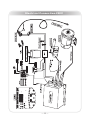
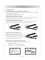
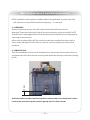
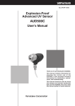
1
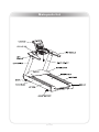
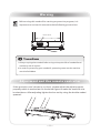
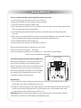
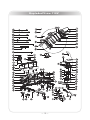
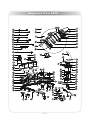
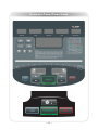
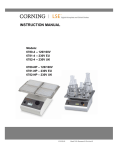
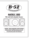
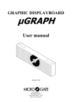
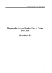
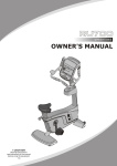
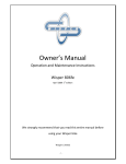
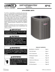
RT700
110V and 220V 12T
! CAUTION
Read all precautions and instructions in this manual before using this
equipment.
Table Of Contents
Important Safety Instructions-------------------------------------------------------------------- 3
Before You Start-------------------------------------------------------------------------------------- 6
Main Parts List---------------------------------------------------------------------------------------- 7
Warning------------------------------------------------------------------------------------------------ 8
Using Method---------------------------------------------------------------------------------------- 9
Warm Up Exercises--------------------------------------------------------------------------------- 10
Power Requirements------------------------------------------------------------------------------ 11
Console Information------------------------------------------------------------------------------- 12
Moving Instructions------------------------------------------------------------------------------- 13
Parts List---------------------------------------------------------------------------------------------- 14
Exploded View-------------------------------------------------------------------------------------- 18
Console Panel Functions------------------------------------------------------------------------- 22
Electrical Connection----------------------------------------------------------------------------- 32
Belt Adjustment and Maintenance------------------------------------------------------------ 34
Impor tant Safety Instructions
IMPORTANT SAFETY INSTRUCTIONS
When using an electrical appliance, basic precautions should always be followed,
including the following:
Read all instructions before using this Treadmill:
DANGER - To reduce the risk of electric shock:
1. Always unplug this appliance from the electrical outlet immediately after
using and before cleaning.
2. Do not reach for a plug that has fallen into water. Unplug immediately.
3. Do not use while bathing or in a shower.
4. Do not place or store the treadmill where it can fall or be pulled into a tub or
sink. Do not place in or drop into water or other liquid.
WARNING - To reduce the risk of burns, fire, electric shock, or injury to
persons:
1. An appliance should never be left unattended when plugged in. Unplug from
outlet when not in use, and before putting on or taking off parts.
2. Do not operate under blanket or pillow. Excessive heating can occur and cause
fire, electric shock, or injury to users.
3. Close supervision is necessary when this treadmill is used by, on, or near
children, invalids, or disabled persons. Keep children away from extended
back, foot support (or other similar parts).
4. Use this treadmill only for its intended use as described in this manual. Do not
use attachments not recommended by the manufacturer.
5. Never operate this treadmill if it has a damaged cord or plug, if it is not working
properly, if it has been dropped or damaged, or dropped into water. Return the
Treadmill to a service center for examination and repair.
6. Do not carry this treadmill by supply cord or use cord as a handle.
7. Keep the cord away from heated surfaces.
8. Never operate the treadmill with the air openings blocked. Keep the air
openings free of lint, hair, and the like. Never operate on a soft surface such as
a bed or couch where the air openings may be blocked.
─3─
Impor tant Safety Instructions
9. Never drop or insert any object into any opening.
10. Do not use outdoors.
11. Do not operate where aerosol (spray) products are being used or where
oxygen is being administered.
12. To disconnect, turn all controls to the off position, then remove plug from
outlet.
13. Connect this Treadmill to a properly grounded outlet only. See Grounding
Instructions.
14. The equipment is designed for commercial use, Maximum load is 200KG.
SAVE THESE INSTRUCTIONS
GROUNDING INSTRUCTION
This product must be grounded. If it should malfunction or breakdown,
grounding provides a path of least resistance for electric current to reduce the
risk of electric shock. This product is equipped with a cord having an equipmentgrounding conductor and a grounding plug. The plug must be plugged into an
appropriate outlet that is properly installed and grounded in accordance with
all local codes and ordinances.
DANGER - Improper connection of the equipment-grounding conductor
can result in a risk of electric shock. Check with a qualified electrician or
serviceman if you are in doubt as to whether the product is properly grounded.
Do not modify the plug provided with the product - if it will not fit the outlet,
have a proper outlet installed by a qualified electrician.
This product is rated more than 15 amperes and is for use on a circuit having a
nominal rating of 120 volts and is factory-equipped with a specific electric cord
and plug to permit connection to a proper electric circuit. Make sure that the
product is connected to an outlet having the same configuration as the plug.
No adapter should be used with this product. If the product must be
reconnected for use on a different type of electric circuit, the reconnection
should be made by qualified service personnel.
─4─
Impor tant Safety Instructions
CAUTION - Risk of Injury to Persons - To Avoid Injury, use extreme caution
when stepping onto or off of a moving belt. Read Instruction Manual Before
Using.
ATTENTION - Risque des blessures aux personnes - Pour éviter des
blessures, avec une extrême prudence en marchant sur ou hors d'une ceinture
mobile. Lisez le manuel d'instruction avant utilisation.
CAUTION - To Reduce The Risk Of Injury From Moving Parts - Unplug
Before Servicing.
ATTENTION - Pour réduire le risque de plessures des pièces mobiles Débranchez avant l'entretien.
WARNING - To Reduce the Risk of Electric Shock - Unplug Before Cleaning
or Servicing.
AVERTISSEMENT - Pour réduire le risque du choc électrique Uébranchez avant le nettoyage ou l'entretien.
─5─
Before You Star t
Remember to take the time to review owner's manuals before you start.
1. Before using this treadmill or starting any exercise program, consult your
physician and accompanied by specialized person. Adjust the speed not
over 8KMH.
2. Take the time to perform the stretching exercise provided to avoid injury.
3. If you have heart problems, and/ or the other diseases, do not use the
treadmill programs without receiving approval from your physician.
4. Stop exercising or call physician if you feel uncomfortable.
5. Do not leave children unsupervised and disabled person near or on the
treadmill. Should be accompanied by supervisors.
6. Running is oxygen exercise, recommended 30 minutes per time is
reasonable.
7. Wear comfortable, good-quality walking or running shoes and appropriate
clothing. Do not with fibre clothing to avoid electrical shock and damage
the treadmill.
8. Do note us the treadmill with bare feet, sandals, socks of stockings to
avoid any risk of injuries. Wear comfortable shoes or cotton socks.
9. Failure to follow these instructions will void the treadmill warranty.
10. If the supply cord is damaged, it must be replaced by the manufacturer or
its service agent or a similarly qualified person in order to avoid a hazard.
─6─
Main parts list
─7─
War ning
Before using this treadmill or starting any exercise program, It is
important to review this manual and the following precautions.
Power switch
1. Always unplug the treadmill after using to keep the life of treadmill and
avoid any risk of injuries.
2. In order to protecting your treadmill, spattering water on the machine
must be forbidden.
Adjustment and Use remote controller
If the ground in user's house is not level, please adjust the adjust support
properly which is marked as A in the below figure to make the machine at a
leveled place. After adjusting tighten the hex nut by using the double-ended
spanner.
─8─
Using Method
Please read carefully and using follow the functions:
1. put the plug in the socket, turn on the switch.
2. grasp the handle firmly, stand on the treadmill.
3. clip the clothes using the safety clip.
4. you can operate this device according as the manual set the lowest speed, first
then increase the speed gradually.
5. you should grasp the handle firmly by one hand, when you operating the
console.
6. Take care to use treadmill. Start from low speed handed to the uprights leaving
from treadmill after reducing speed and stopping all functions.
7. Press Safety Switch on emergency.
8. Keep warm and relax your body after workout.
Exercise time and exercise frequency at a time:
Exercise time: 30minuates----Normal;
Exercise frequency: Warm your body by 10---20minutes under 8Kph,
then increase speed accordingly.
CE Switch and Safety Switch Introduction
When the treadmill is running, the user can
press the red safety switch directly if he
wants to stop it. Then the treadmill will stop
slowly. If the user encounters emergency
when he using the treadmill he should haul
the safety clip linked with red wire, it will
triger the safety switch to step.
Operation:
1. Press the CE switch and keep it at the low position, tie the safety clip to your
cloth, then start the treadmill for exercise.
2. If there is any emergency, the clip tied to your cloth will pull the CE switch and
it will come to the origal position. In the mean time, the treadmill will stop
completely and the main power will be cut.
Warning: When use above methed to stop running, the running belt will last
running for several seconds before completely stop.
─9─
War m Up Exercises
EXERCISE GUIDELINES
WARNING! Before beginning this or any exercise program, you should consult your
physician. This is especially important for individuals over the age of 35 or individuals
with pre-existing health problems.
Warming up prepares the body for the exercise by increasing circulation, supplying more
oxygen to the muscles and raising body temperature. Begin each workout with 5 to 10
minutes of stretching and light exercise to warm up. The photos on this page show
several forms of basic stretching you may perform before your workouts. In order to
achieve an adequate warm-up, perform each stretch three times.
TOE TOUCH STRETCH
Stand, bending your knees slightly and slowly bend forward
from your hips. Allow your back and shoulders to relax as you
reach down toward your toes as far as possible. Hold for 15
counts, then relax. This will stretch your hamstrings, back of
knees, and back.
HAMSTRING STRETCH
Sit with one leg extended. Bring the sole of the opposite foot
toward you and rest it against the inner thigh of your
extended leg. Reach toward your toes as far as possible. Hold
for 15 counts, then relax. This will stretch your hamstrings,
lower back, and groin.
CALF/ACHILLES STRETCH
With one leg in front of the other, reach forward and place
your hands against a wall. Keep your back leg straight and
your back foot flat on the floor. Bend your front leg, lean
forward and move your hips toward the wall. Hold for 15
counts, then relax. To cause further stretching of the Achilles
tendon, bend your back leg as well. This will stretch your
calves, Achilles tendons, and ankles.
QUADRICEPS STRETCH
With one hand against a wall for balance, reach back and
grasp one foot with your other hand. Bring your heel as close
to your buttocks as possible. Hold for 15 counts, then relax.
This will stretch your quadriceps and hip muscles.
INNER THIGH STRETCH
Sit with the soles of your feet together and your knees
outward. Pull your feet toward your groin area as far as
possible. Hold for 15 counts, then relax. This will stretch your
quadriceps and hip muscles.
─ 10 ─
Power Requirements
IMPROPER CONNECTION OF THE EQUIPMENT GROUNDING CONNECTOR
CAN RESULT IN A RISK OF AN ELECTRIC SHOCK. CHECK WITH A QUALIFIED
ELECTRICIAN OR SERVICE MAN IF YOU ARE IN DOUBT AS TO WHETHER THE
PRODUCT IS PROPERLY GROUNDED. DO NOT MODIFY THE PLUG PROVIDED
WITH THE PRODUCT. IF PLUG WILL NOT FIT THE OUTLET, HAVE A PROPER
OUTLET INSTALLED BY A QUALIFIED ELECTRICIAN.
This treadmill can be seriously damaged by sudden voltage changes in your
home's electrical power. Voltage spikes, surges, and noise interference can
result from weather conditions or from other appliances being turned on or off.
This treadmill must be grounded to reduce the risk of electrical shock.
Grounding provides a path of least resistance for electric current should the
treadmill malfunction. Always plug the power cord into an appropriate outlet
that is properly installed and grounded in accordance with all local codes and
ordinances.
─ 11 ─
Console Infor mation
Before beginning your workout, check your normal resting heart rate. Place your
fingers lightly against your neck, or against your wrist over the main artery. After
finding your pulse, count the number of beats in 10 seconds. Multiply the number
of beats by six to determine your pulse rate per minute. We recommend taking your
heart rate at these times; at rest, after warming up, during your workout and two
minutes into your cool down, to accurately track your progress as it relates to better
fitness.
During your first several months of exercising, the AHA recommends aiming for the
lower part of the target heart rate zone-60%, then gradually pro-gressing up to 75%.
According to the AHA, exercising above 75% of your maximum heart rate may be
too strenuous unless you are in top physical condition. Exercising below 60% of
your maximum will result in minimal cardiovascular conditioning.
Check your pulse recovery rate – If your pulse is over 100 bpm five minutes after you
stop exercising, or if it's higher than normal the morning after exercising, your
exertion may have been too strenuous for your current fitness level. Rest and reduce
the intensity next time.
Fitness Safety The target
heart rate chart indicates
average rate zones for
different ages. A variety of
different factors (including
medication, emotional
state, temperature and
other conditions) can
affect the target heart rate
zone that is best for you.
Your physician or health
care professional can help
you determine the exercise
intensity that is appropriate for your age and
condition.
─ 12 ─
Moving Instructions
Caution! To avoid the risk of injury, never attempt to move the treadmill while it is
operating. To reduce the possibility of injury while lifting, bend your legs and keep
your back straight. As you raise the treadmill, lift using your legs, not your back. In
order to raise or lower the treadmill safely, you must be able to lift 220 pounds
(100kg). It is suggested you always use the aid of a second person when moving the
treadmill.
Lift the treadmill back then move it to the desired location. Carefully put down it on
the position. Do not attempt to move the treadmill over an uneven or rough surface.
Note: The treadmill's angle can not exceed 30 degrees when lifted the treadmill back.
─ 13 ─
Par ts List-110V
Item No. Description
QTY Item No. Description
QTY
1
Console Frame
1
55
A-Zone Down Cover
1
2
Left Upright
1
56
Emergency Switch Key
1
3
Right Upright
1
57
Fan Key
2
4
Deck Frame
1
58
Cool Down\Pause Key
2
5
Elevating Frame
1
59
Limit Key Fixing Plate
1
6
Left Handle Frame
1
60
Emergency Switch Baffle
1
7
Right Handle Frame
1
61
Air Grid
1
8
Console Plate Frame
1
62
Air Up Cover
1
9
Motor Fixing Plate
1
63
A-Zone Insert
1
10
Dust Proof Plate
1
64
Console Back Cover
1
11
Front Motor Cover Fixing L Plate
2
67
Console Bottom Plate
1
12
Motor Cover Fixing L Plate
2
68
Switch Fixing Plate
1
13
Eleavate Rotational Sleeve
2
71
Nylon Shaft
1
14
Front Cover Fixing Plate
2
72
Left Side
1
15
Console Linked Plate
1
73
Right Side
1
16
Middle Z Fixing Plate
1
74
Left Steel Side
1
17
Running Belt
1
75
Right Steel Side
1
18
Controller U Fixing Plate
1
76
Reposition Rack
1
19
Elevating Frame Fixing Shoulder Bolt
2
77
Restrict Spring
1
20
Motor Cover
1
78
Left Pulse
1
21
Left Front Decorative Cover
1
79
Right Pulse
1
22
Right Front Decorative Cover
1
80
Console Component
1
24
Running Board
1
81
Flat Head Hexagon Riveted Nuts M8
25
Left Rear Adjusting Seat
1
82
Countersunk Head Hexagon Riveted Nuts M5
26
Right Rear Adjusting Seat
1
83
Phillip Screw M4*40
2
27
Left Rear Decorative Cover
1
84
Phillip Screw M5*15
39
28
Right Rear Decorative Cover
1
85
Phillip Screw M5*20
4
29
Middle Protective Cover
1
86
Phillip Screw M5*35
6
30
Switch Cover
1
87
Phillip Screw St2.9*6.5
17
32
Front Roller
1
88
Phillip Screw St2.9*9.5
4
33
Rear Roller
1
89
Phillip Screw St4.2*13
9
35
Left Handle
1
90
Phillip Screw St4.2*50
4
36
Right Handle
1
91
Hex Head Bolt M6*15
4
37
Console Left Up Cover
1
92
Socket Head Cap Screw M8*15
4
38
Console Right Up Cover
1
93
Socket Head Cap Screw M8*20
8
39
Console Left Down Cover
1
94
Socket Head Cap Screw M8*55
2
40
Console Right Down Cover
1
95
Hex Nut M4
2
41
Fan Fixing Plate
1
96
Locknut M8
2
43
Left Routing Cover
1
97
Washer Φ9*Φ22*2
14
44
Right Routing Cover
1
98
Split Damping Ring Φ9
1
45
Left Bolt Cover
1
99
Clip Nut
4
46
Right Bolt Cover
1
100
Safe Key Clamp
1
47
Cup Holder
1
101
Console Overlay
1
48
Left Signing Light Fixing Plate
1
102
Sign Paster
1
49
Right Signing Light Fixing Plate
1
104
A Zone Up Overlay
1
52
Console Signing Light Cover
2
105
A Zone Down Overlay
1
53
Earphone Hole Plug
1
106
Left Handle Key Paster
1
54
A-Zone Up Cover
1
107
Right Handle Key Paster
1
─ 14 ─
4
18
Par ts List-110V
Item No. Description
QTY Item No. Description
QTY
108
Console Pcb
1
179
Socket Head Cap Screw M6*60
2
109
Key Board
1
180
Socket Head Cap Screw M6*20
20
110
Joint 1
1
181
Locknut M3
6
111
Joint 2
1
182
Locknut M8
12
112
Joint 3
1
183
Washer Φ11*Φ23*2
6
113
12V Power Wire
1
184
Hexagon Socket Countersunk Head Cap Head Screw M8*35
6
114
Switch Pcb
1
185
Circlip For Shaft
2
115
Fan
1
186
Washer
4
116
Pulse Plate
1
187
Socket Head Cap Screw M8*15
2
117
Linked Wire Fron Pulse Pcb To Pcb
1
188
Socket Head Cap Screw M8*30
10
118
Pulse Connect Wire
1
189
Socket Head Cap Screw M8*80
2
119
Receptor
1
190
Hex Head Bolt M10*165
2
120
Spd And Incl Pcb
2
191
Hex Head Bolt M10*180
2
121
Spd And Incl Harness
2
192
Power Plate Isolation Pillar
4
122
Emergency Switch
2
193
Power Wire Fixing Plate
1
123
Emergency Switch Wire
2
194
Band Cable
10
124
Console Wire Up
1
195
Double Wrench
1
125
Ferrite
3
196
Lug Wrench
1
126
Ferrite
2
197
Hexagonal Socket Wrench
1
150
Adjust Bumper
2
198
Double Wrench
1
151
Bumper A
4
199
Lug Wrench
1
152
Bumper B
4
200
Hexagonal Socket Wrench
153
Bumper
4
201
Tape
154
Insulation Bumper
1
202
Locknut M5
2
155
Lubricating Tube Fixing Plate
1
203
Lubricating Tube 1
1
156
V-Belt
1
205
Wheel
2
157
Lubricating Controller Fixing Plate
1
206
Locknut M10
4
158
Neck Bush
4
207
Locknut M12
2
159
Clip Nut M6
6
208
Washer Φ9*Φ22*2
10
160
Insulation Spacer
4
209
Circuit Break Switch
2
161
Carriage Bolt M8*40
1
210
Earth Wire
2
162
Countersunk Head Hexagon Riveted Nuts M5
12
211
Motor
1
163
Countersunk Head Hexagon Riveted Nuts M6
2
212
Transducer
1
164
Flat Head Hexagon Riveted Nuts M6
18
213
Main Switch
1
165
Flat Head Hexagon Riveted Nuts M8
6
214
Connect Wire
4
166
Hex Flange Nut M8
9
215
Console Wire Down
1
167
Hex Flange Nut M16
2
216
Connect Wire
2
168
Hex Head Bolt M8*150
6
217
Connect Wire
2
169
Hex Head Bolt M10*25
4
218
Lubricating Controller
1
170
Hex Head Bolt M10*50
1
219
Fuel Injection Pump
1
171
Hex Head Bolt M10*130
1
221
Protective Sleeve
1
172
Phillip Screw M3*10
2
224
Actuator
1
173
Phillip Screw M4*10
4
225
Power Outlet
1
174
Phillip Screw M4*10
2
226
Power Wire
1
175
Phillip Screw M4*8
5
260
Ground Bumper
1
176
Phillip Screw St4.2*13
18
261
Serrated Lock Washers Φ10
4
177
Phillip Screw M5*20
18
262
Serrated Lock Washers Φ8
4
178
Phillip Screw M6*30
6
─ 15 ─
1
3.8
Par ts List-220V
Item No. Description
QTY Item No. Description
QTY
1
Console Frame
1
55
A-ZONE Down Cover
1
2
Left Upright
1
56
Emergency Switch Key
1
3
Right Upright
1
57
Fan Key
2
4
Deck Frame
1
58
COOL DOWN\PAUSE Key
2
5
Elevating Frame
1
59
Limit Key Fixing Plate
1
6
Left Handle Frame
1
60
Emergency Switch Baffle
1
7
Right Handle Frame
1
61
Air Grid
1
8
Console Plate Frame
1
62
Air Up Cover
1
9
Motor Fixing Plate
1
63
A-ZONE Insert
1
10
Dust Proof Plate
1
64
Console Back Cover
1
11
Front Motor Cover Fixing L Plate
2
67
Console Bottom Plate
1
12
Motor Cover Fixing L Plate
2
68
Switch Fixing Plate
1
13
Eleavate Rotational Sleeve
2
71
Nylon Shaft
1
14
Front Cover Fixing Plate
2
72
Left Side
1
15
Console Linked Plate
1
73
Right Side
1
16
Middle Z Fixing Plate
1
74
Left Steel Side
1
17
Running Belt
1
75
Right Steel Side
1
18
Controller U Fixing Plate
1
76
Reposition Rack
1
19
Elevating Frame Fixing Shoulder Bolt
2
77
Restrict Spring
1
20
Motor Cover
1
78
Left Pulse
1
21
Left Front Decorative Cover
1
79
Right Pulse
1
22
Right Front Decorative Cover
1
80
Console Component
1
24
Running Board
1
81
Flat Head Hexagon Riveted Nuts M8
25
Left Rear Adjusting Seat
1
82
Countersunk Head Hexagon Riveted Nuts M5
26
Right Rear Adjusting Seat
1
83
Phillip Screw M4*40
2
27
Left Rear Decorative Cover
1
84
Phillip Screw M5*15
39
28
Right Rear Decorative Cover
1
85
Phillip Screw M5*20
4
29
Middle Protective Cover
1
86
Phillip Screw M5*35
6
30
Switch Cover
1
87
Phillip Screw ST2.9*6.5
17
32
Front Roller
1
88
Phillip Screw ST2.9*9.5
4
33
Rear Roller
1
89
Phillip Screw ST4.2*13
9
35
Left Handle
1
90
Phillip Screw ST4.2*50
4
36
Right Handle
1
91
Hex Head Bolt M6*15
4
37
Console Left Up Cover
1
92
Socket Head Cap Screw M8*15
4
38
Console Right Up Cover
1
93
Socket Head Cap Screw M8*20
8
39
Console Left Down Cover
1
94
Socket Head Cap Screw M8*55
2
40
Console Right Down Cover
1
95
Hex Nut M4
2
41
Fan Fixing Plate
1
96
Locknut M8
2
43
Left Routing Cover
1
97
Washer Φ9*Φ22*2
14
44
Right Routing Cover
1
98
Split Damping Ring Φ9
1
45
Left Bolt Cover
1
99
Clip Nut
4
46
Right Bolt Cover
1
100
Safe Key Clamp
1
47
Cup Holder
1
101
Console Overlay
1
48
Left Signing Light Fixing Plate
1
102
Sign Paster
1
49
Right Signing Light Fixing Plate
1
104
A ZONE Up Overlay
1
52
Console Signing Light Cover
2
105
A ZONE Down Overlay
1
53
Earphone Hole Plug
1
106
Left Handle Key Paster
1
54
A-ZONE Up Cover
1
107
Right Handle Key Paster
1
─ 16 ─
4
18
Par ts List-220V
Item No. Description
QTY Item No. Description
QTY
108
Console Pcb
1
180
Socket Head Cap Screw M6*20
109
Key Board
1
181
Locknut M3
6
110
Joint 1
1
182
Locknut M8
12
111
Joint 2
1
183
Washer Φ11*Φ23*2
6
112
Joint 3
1
184
Hexagon Socket Countersunk Head Cap Head Screw M8*35
6
113
12V Power Wire
1
185
Circlip For Shaft
2
114
Switch Pcb
1
186
Washer
4
115
Fan
1
187
Socket Head Cap Screw M8*15
2
116
Pulse Plate
1
188
Socket Head Cap Screw M8*30
10
117
Linked Wire Fron Pulse Pcb To PCB
1
189
Socket Head Cap Screw M8*80
2
118
Pulse Connect Wire
1
190
Hex Head Bolt M10*165
2
119
Receptor
1
191
Hex Head Bolt M10*180
2
120
Spd And Incl Pcb
2
192
Power Plate Isolation Pillar
4
121
Spd And Incl Harness
2
193
Power Wire Fixing Plate
1
122
Emergency Switch
2
194
Band Cable
10
123
Emergency Switch Wire
2
195
Double Wrench
1
124
Console Wire Up
1
196
Lug Wrench
1
125
Ferrite
3
197
Hexagonal Socket Wrench
1
126
Ferrite
2
198
Double Wrench
1
150
Adjust Bumper
2
199
Lug Wrench
1
151
Bumper A
4
200
Hexagonal Socket Wrench
152
Bumper B
4
201
Tape
153
Bumper
4
202
Locknut M5
2
154
Insulation Bumper
1
203
Lubricating Tube 1
1
155
Lubricating Tube Fixing Plate
1
205
Wheel
2
156
V-Belt
1
206
Locknut M10
4
157
Lubricating Controller Fixing Plate
1
207
Locknut M12
2
158
Neck Bush
4
208
Washer Φ9*Φ22*2
10
159
Clip Nut M6
6
209
Circuit Break SWITCH
2
160
Insulation Spacer
4
210
Earth Wire
2
161
Carriage Bolt M8*40
1
211
Motor
1
162
Countersunk Head Hexagon Riveted Nuts M5
12
212
Transducer
1
163
Countersunk Head Hexagon Riveted Nuts M6
2
213
Main Switch
1
164
Flat Head Hexagon Riveted Nuts M6
18
214
Connect Wire
4
165
Flat Head Hexagon Riveted Nuts M8
6
215
Console Wire Down
1
166
Hex Flange Nut M8
9
216
Connect Wire
2
167
Hex Flange Nut M16
2
217
Connect Wire
2
168
Hex Head Bolt M8*150
6
218
Lubricating Controller
1
169
Hex Head Bolt M10*25
4
219
Fuel Injection Pump
1
170
Hex Head Bolt M10*50
1
221
Protective Sleeve
1
171
Hex Head Bolt M10*130
1
222
Inductance
1
172
Phillip Screw M3*10
2
223
Filter
1
173
Phillip Screw M4*10
4
224
Actuator
1
174
Phillip Screw M4*10
2
225
Power Outlet
1
175
Phillip Screw M4*8
5
226
Power Wire
1
176
Phillip Screw ST4.2*13
18
260
Ground Bumper
1
177
Phillip Screw M5*20
18
261
Serrated Lock Washers Φ10
4
178
Phillip Screw M6*30
6
262
Serrated Lock Washers Φ8
4
179
Socket Head Cap Screw M6*60
2
─ 17 ─
20
1
3.8
Exploded View-110V
─ 18 ─
Exploded View-110V
─ 19 ─
Exploded View-220V
─ 20 ─
Exploded View-220V
─ 21 ─
Console Panel Functions
─ 22 ─
Console Panel Functions
110V
220V
INPUT VOLTGAE:
110-120V~ 50/60Hz
RATED CURRENT:
18A
SPEED RANGE:
1.0-25KPH
INCLINE RANGE:
0-15%
DISPLAY:
SPEED, TIME, PULSE, INCLINE, STEPS,
CALORIE, DISTANCE, DOT MATRIX
INPUT VOLTGAE:
220-240V~ 50/60Hz
RATED POWER:
3100W
SPEED RANGE:
1.0-25KPH
INCLINE RANGE:
0-15%
DISPLAY:
SPEED, TIME, PULSE, INCLINE, STEPS,
CALORIE, DISTANCE, DOT MATRIX
CONSOLE PANEL FUNCTION
1. TIME WINDOW
Indicates elapsed time after pressing start in minutes and seconds (0-99minutes,
0-59seconds).
2. SPEED WINDOW
Indicates workout speed MPH (miles per hour) or KPH (kilometer per hour) in 0.1
increments.
3. INCLINE WINDOW
Indicates incline in percent of grade 0—15% in 1 increments.
4. PULSE WINDOW
Indicates user's current heart rate (BPM).
5. CALORIES WINDOW
Indicates estimated calories used based on 68Kg person at the indicated speed,
incline, and time.
6. DISTANCE WINDOW
Indicates Kilometers or Miles traveled in 0.01 increments up to 9.99 and 0.1
increments starting at 10.0 (Range 0.01---999).
7 STEPS WINDOW
Indicates user exercise steps.
─ 23 ─
Console Panel Functions
8. Dot MATRIX
8.1 Indicates the lap count and displays which lap you are on. (One lap is 400
meters)
8.2 Indicates 'PRESS QUICK START OR SELECT PROGRAM TO BEGIN' when turn on
power.
8.3 Indicates message when enter value.
8.4 Indicates workout curve in Program mode.
CONSOLE BUTTONS
1. START
This button is used to start the current program.
2. STOP
Press once, Speed drop to 0, every other window remains un-changed.
Hold for 3 seconds, console resets.
3. SPEED+ and SPEEDThis button is used to adjust the speed of the treadmill during workout.
This button is also used to adjust the values when setting up your workout.
4. INCLINE+ and INCLINEThese buttons are used to adjust the incline of the treadmill during workout.
5. NUMERIC KEYPAD
These buttons are used to cycle through to the desired data.
6. OK
This button is used to enter value of program mode.
7. MANUAL ONE TOUCH
This button is used to select workout "manual mode".
8. CARDIO ONE TOUCH
This button is used to select workout "cardio mode".
9. INTERVAL ONE TOUCH
This button is used to select workout "interval mode".
10. BURN CALORIES ONE TOUCH
This button is used to select workout "burn cardies mode".
11. HEART RATE ONE TOUCH
This button is used to select workout "heart rate mode".
─ 24 ─
Console Panel Functions
12. TARGET ONE TOUCH
This button is used to select workout "target mode".
13. COOLDOWN
This button is used select workout "cool down mode".
14. DELETE (▲) BUTTON
This button is used delete data.
15. FAN BUTTON
Turn on and turn off the fan and adjust the fan speed.
CONSOLE OPERATION
1. QUICK START/MANUAL MODE
1.1 Plug into surge protector outlet. Stand on the treadmill and straddle belt.
1.2 Turn on power.
1.3 The LED screen scrolls "PRESS QUICK START OR SELECT PROGRAM TO BEGIN”.
1.3.1 If press start button through manual mode;
1.3.2 If Manual, Cardio, Interval, Burn Calories, Heart Rate, Target, Advanced is
selected.
1.4 Press STOP button belt will stop, Hold for 3 seconds, console resets.
2. PROGRAM MODE
When console turns on, the LED screen scrolls "PRESS QUICK START OR SELECT
PROGRAM TO BEGIN”. If Manual, Cardio, Interval, Burn Calories, Heart Rate, Target,
Advanced is selected.
2.1 If Manual is selected
2.1.1 LED scrolls "MANUAL MODE: ENTER WEIGHT";
2.1.2 LED displays "70";
2.1.3 Uses speed keys or Speed adjustment keys: "+" or "-" to adjust the default
value;
2.1.4 Press OK to confirm;
2.1.5 LED scrolls "ENTER TIME";
2.1.6 LED displays "20";
2.1.7 Uses speed keys or Speed adjustment keys: "+" or "-" to adjust the default
value;
─ 25 ─
Console Panel Functions
2.1.8 Press OK or QUICK START to confirm;
2.1.9 Top time LED updates;
2.1.10 LED displays "3", "2", "1";
2.1.11 Belt starts moving.
2.2 If Cardio is selected
2.2.1 LED scrolls "CARDIO MODE: ENTER WEIGHT";
2.2.2 LED displays "70";
2.2.3 Uses speed keys or Speed adjustment keys: "+" or "-" to adjust the default
value;
2.2.4 Press OK to confirm;
2.2.5 LED scrolls "ENTER TIME";
2.2.6 LED displays "20";
2.2.7 Uses speed keys or Speed adjustment keys: "+" or "-" to adjust the default
value;
2.2.8 Press OK or QUICK START to confirm;
2.2.9 Top time LED updates;
2.2.10 LED displays "3", "2", "1";
2.2.11 Belt starts moving.
2.3 If Interval is selected
2.3.1 LED scrolls "INTERVAL MODE: ENTER WEIGHT";
2.3.2 LED displays "70";
2.3.3 Uses speed keys or Speed adjustment keys: "+" or "-" to adjust the default
value;
2.3.4 Press OK to confirm;
2.3.5 LED scrolls "ENTER TIME";
2.3.6 LED displays "20";
2.3.7 Uses speed keys or Speed adjustment keys: "+" or "-" to adjust the default
value;
2.3.8 Press OK to confirm;
2.3.9 Top time LED updates;
2.3.10 LED scrolls "ENTER LOWER SPEED LIMIT";
2.3.11 LED displays "8";
─ 26 ─
Console Panel Functions
2.3.12 Uses speed keys or Speed adjustment keys: "+" or "-" to adjust the default
value;
2.3.13 Press OK to confirm;
2.3.14 LED scrolls "ENTER UPPER SPEED LIMIT";
2.3.15 LED displays "10";
2.3.16 Uses speed keys or Speed adjustment keys: "+" or "-" to adjust the default
value;
2.3.17 Press OK or QUICK START to confirm;
2.3.18 LED displays "3", "2", "1";
2.3.19 Belt starts moving.
2.4 If Burn Calories is selected
2.4.1 LED scrolls "BURN CALORIES MODE: ENTER MAX SPEED";
2.4.2 LED displays "10";
2.4.3 Uses speed keys or Speed adjustment keys: "+" or "-" to adjust the default
value;
2.4.4 Press OK to confirm;
2.4.5 LED scrolls "ENTER MAX INCLINE";
2.4.6 LED displays "10";
2.4.7 Uses speed keys or Speed adjustment keys: "+" or "-" to adjust the default
value;
2.4.8 Press OK or QUICK START to confirm;
2.4.9 LED displays "3", "2", "1";
2.2.10 Belt starts moving.
2.5 If Heart Rate is selected
LED scrolls "HEART RATE TRAINING: 1= "HR 65%" 2= "HR 75%" 3= "HR 85%";
Uses speed keys;
2.5.1 If 1 is selected;
2.5.1.1 LED scrolls "HR 65%: ENTER WEIGHT";
2.5.1.2 LED displays "70";
2.5.1.3 Uses speed keys or Speed "+" or "-" to adjust the default value;
2.5.1.4 Press OK to confirm;
2.5.1.5 LED scrolls "ENTER TIME";
─ 27 ─
Console Panel Functions
2.5.1.6 LED displays "20";
2.5.1.7 Uses speed keys or Speed "+" or "-" keys to adjust the default value;
2.5.1.8 Press OK to confirm;
2.5.1.9 LED scrolls "ENTER AGE";
2.5.1.10 LED displays "40";
2.5.1.11 Uses speed keys or Speed adjustment keys: "+" or "-" to adjust the default
value;
2.5.1.12 Press OK or QUICK START to confirm;
2.5.1.13 LED displays "3", "2", "1";
2.5.1.14 Belt starts moving.
2.5.2 If 2 is selected;
2.5.2.1 LED scrolls "HR 75%: ENTER WEIGHT";
2.5.2.2 Same as above.
2.5.3 If 3 is selected;
2.5.3.1 LED scrolls "HR 85%: ENTER WEIGHT";
2.5.3.2 Same as above.
2.6 If Target is selected
LED scrolls "TARGET TRAINING: 1= "CALORIES TARGET" 2= "DISTANCE TARGET" 3=
“TIME TARGET";
Uses speed keys;
2.6.1 If 1 is selected;
2.6.1.1 LED scrolls "CALORIES TARGET: ENTER CALORIES";
2.6.1.2 LED displays "100";
2.6.1.3 Uses speed keys or Speed adjustment keys: "+" or "-" to adjust the default
value;
2.6.1.4 Press OK to confirm;
2.6.1.5 LED scrolls "ENTER WEIGHT";
2.6.1.6 LED displays "70";
2.6.1.7 Uses speed keys or Speed adjustment keys: "+" or "-" to adjust the default
value;
2.6.1.8 Press OK or QUICK START to confirm;
2.6.1.9 LED displays "3", "2", "1";
2.6.1.10 Belt starts moving.
─ 28 ─
Console Panel Functions
2.6.2 If 2 is selected;
2.6.2.1 LED scrolls "DISTANCE TARGET: ENTER DISTANCE";
2.6.2.2 LED displays "5KM";
2.6.2.3 Uses speed keys or Speed adjustment keys: "+" or "-" to adjust the default
value;
2.6.2.4 Press OK or QUICK START to confirm;
2.6.2.5 LED displays "3", "2", "1";
2.6.2.6 Belt starts moving.
2.6.3 If 3 is selected;
2.6.3.1 LED scrolls "TIME TARGET: ENTER TIME";
2.6.3.2 LED displays "30";
2.6.3.3 Uses speed keys or Speed adjustment keys: "+" or "-" to adjust the default
value;
2.6.3.4 Press OK or QUICK START to confirm;
2.6.3.5 LED displays "3", "2", "1";
2.6.3.6 Belt starts moving.
2.7 If Advanced is selected
LED scrolls "ADVANCED TRAINING: 1= "STEPS" 2= "EVENTS" 3= "OTHERS";
Uses speed keys;
2.7.1 If 1 is selected;
LED scrolls "1= 6K STEPS, 2= 8K STEPS, 3=CUSTOM STEPS";
2.7.1.1 If 1 is selected, LED displays "3", "2", "1", Belt starts moving;
2.7.1.2 If 2 is selected, LED displays "3", "2", "1", Belt starts moving;
2.7.1.3 If 3 is selected;
(1) LED scrolls "CUSTOM STEPS: ENTER STEPS";
(2) LED displays "5K";
(3) Uses speed keys or Speed adjustment keys: "+" or "-" to adjust the default
value;
(4) Press OK or QUICK START to confirm;
(5) LED displays "3", "2", "1";
(6) Belt starts moving.
2.7.2 If 2 is selected;
LED scrolls "1= 5KM RUN, 2= 10KM RUN, 3=CUSTOM DISTANCE";
─ 29 ─
Console Panel Functions
2.7.2.1 IF 1 IS SELECTED, LED DISPLAYS "3", "2", "1", BELT STARTS MOVING;
2.7.2.2 IF 2 IS SELECTED, LED DISPLAYS "3", "2", "1", BELT STARTS MOVING;
2.7.2.3 IF 3 IS SELECTED;
(1) LED SCROLLS "CUSTOM DISTANCE: ENTER DISTANCE";
(2) LED DISPLAYS "5KM";
(3) USES SPEED KEYS OR SPEED ADJUSTMENT KEYS: "+" OR "-" TO ADJUST THE
DEFAULT VALUE;
(4) PRESS OK OR QUICK START TO CONFIRM;
(5) LED DISPLAYS "3", "2", "1";
(6) BELT STARTS MOVING.
2.7.3 IF 3 IS SELECTED;
LED SCROLLS "OTHER ADVANCED PROGRAMS: 1= HILL";
2.7.3.1 IF 1 IS SELECTED;
(1) LED DISPLAYS "HILL";
(2) PRESS OK OR QUICK START TO CONFIRM;
(3) LED DISPLAYS "3", "2", "1";
(4) BELT STARTS MOVING.
3. TREADMILL ERROR MESSAGES
3.1 Communication Error message: ER01
3.1.1 Check console and the main communication cable connection;
3.1.2 Check inverter and the main communication cable connection;
3.1.3 Replace inverter;
3.1.4 Replace console.
3.2 Elevation Error messages: ER02
3.2.1 Check power cable of actuator and inverter connection;
3.2.2 Check cable of sensor of actuator and inverter connection;
3.2.3 Replace actuator;
3.2.4 Replace inverter.
─ 30 ─
Console Panel Functions
3.3 Safe-key Error message: ER03
3.3.1 Check safe-key button;
3.3.2 Check cable of safe-key;
3.3.3 Replace safe-key PCB;
3.3.4 Replace console.
3.4 Over current message: ER04
3.4.1 Add silicon to run belt and board;
3.4.2 Replace inverter;
3.4.3 Replace motor.
3.5 Lower voltage message: ER05
3.5.1 Check power AC 200-240V (105-125V ).
3.6 Over load message: ER06
3.6.1 Add silicon to run belt and board;
3.6.2 Replace run belt and board;
3.6.3 Replace inverter;
3.6.4 Replace motor.
3.7 Emergency stop message: ER07
3.7.1 Reset Emergency switch then press STOP button;
3.7.2 Check cable of Emergency switch and Emergency switch connection;
3.7.3 Replace Emergency switch;
3.7.4 Replace inverter.
3.8 The console no power
3.8.1 Check the AC power;
3.8.2 Turn on the power switch;
3.8.3 Check the communication cable and console connection;
3.8.4 Check the communication cable and inverter connection;
3.8.5 Replace the communication cable;
3.8.6 Replace the power cable.
─ 31 ─
Electrical Connection-110V
─ 32 ─
Electrical Connection-220V
─ 33 ─
Belt Adjustment and Maintenance
1. Belt Adjustment:
Belt adjustment and tension performs two functions:
*The distance between belt and motor cover from left to right within +/-5MM,
then needed to be adjusted.
*Adjust belt by speed not more than 4KMH.
A. Running Belt is shifting to the right:
Using hex key provided, turn the right rear roller adjustment bolt turn in the
clockwise direction shown as below or on the contrary direction.
B. Running Belt is shifting to the right:
Using hex key provided, turn the right rear roller adjustment bolt turn in the
clockwise direction shown as below or on the contrary direction.
B
A
Running belt is Slipping during use:
Slight running belt slipping is on normal
while using for a period using the hex key
provided, turn both left and right rear roller
adjustment bolts in the same distance.
See the correct running belt shown as below:
A. The distance between running belt and board is within
15-20mm----Normal
Over 20mm----needed to be adjustded
Under 15mm----needed to be adjustded
─ 34 ─
Belt Adjustment and Maintenance
B. The speed for running belt is 5KMH, hold on the handrail, stand on the side
rail, one foot on the belt but without slipping----it's normal.
2. CLEANING:
Routine cleaning of your unit will extend extend the life of your unit.
Warning! To prevent electrical shock, be sure the power to the treadmill is OFF
and the unit is unplugged form the wall electrical outlet before attempting any
cleaning or mainteance.
After each workout: Wipe off the console and other treadmill surfaces with a
clean, water dampened soft cloth to remove excess perspiration. After each
workout.
15mm
3. LUBRICATION:
This kind treadmill have a user-friendly fuction automatic lubrication. there is a
program that will lubricate the running belt when the distance reach the setting
point.
Add lubrication to the transferring lubrication pump-unit when lubrication
level in the transferring lubrication pump-unit is under 15mm.
─ 35 ─