1
>kNÂ@ÌÌÌÌÌÌÌÌÌÌÌÌÌÌÌÌÌÌÌÌÌÌÌÌ
¥¥Ê-;ÐÔÌÌÌÌÌÌÌÌÌÌÌÌÌÌÌÌÌÌÌÌÌÌÌÌ
3Åk¿ÅÌ×bk
3URSULHWDU\6WDWHPHQW
This manual contains proprietary information of Zebra Technologies Corporation. It is intended solely for the
information and use of parties operating and maintaining the equipment described herein. Such proprietary
information may not be used, reproduced, or disclosed to any other parties for any other purpose without the
expressed written permission of Zebra Technologies Corporation.
3URGXFW,PSURYHPHQWV
Continuous improvement of products is a policy of Zebra Technologies Corporation. All specifications and
signs are subject to change without notice.
)&&&RPSOLDQFH6WDWHPHQW
This equipment has been tested and found to comply with the limits for a Class A digital device, pursuant to
Part 15 of the FCC Rules. These limits are designed to provide reasonable protection against harmful
interference when the equipment is operated in a commercial environment. This equipment generates, uses,
and can radiate radio frequency energy and, if not installed and used in accordance with the instructions, may
cause harmful interference to radio communications. Operation of this equipment in a residential area is likely
to cause harmful interference in which case the user will be required to correct the interference at his own
expense.
To ensure compliance, this print engine must be used with a Shielded Power Cord and Shielded
Communication Cables.
“The user is cautioned that any changes or modifications not expressly approved by Zebra Technologies
Corporation could void the user’s authority to operate the equipment.”
&DQDGLDQ'2&&RPSOLDQFH6WDWHPHQW
This digital apparatus does not exceed the Class A limits for radio noise emissions from digital apparatus as set
out in the radio interference regulations of the Canadian Department of Communications.
/LDELOLW\'LVFODLPHU
Zebra Technologies Corporation takes steps to ensure that its published Engineering Specifications and
Manuals are correct; however, errors do occur. Zebra Technologies Corporation reserves the right to correct
any such errors and disclaims liability resulting therefrom.
1R/LDELOLW\IRU&RQVHTXHQWLDO'DPDJH
In no event shall Zebra Technologies Corporation or anyone else involved in the creation, production, or
delivery of the accompanying product (including hardware and software) be liable for any damages
whatsoever (including, without limitation, damages for loss of business profits, business interruption, loss of
business information, or other pecuniary loss) arising out of the use of or the results of use or inability to use
such product, even if Zebra Technologies Corporation has been advised of the possibility of such damages.
Because some states do not allow the exclusion or limitation of liability for consequential or incidental
damages, the above limitation may not apply to you.
&RS\ULJKWV
The copyrights in this manual and the label print engine described therein are owned by Zebra Technologies
Corporation. All rights are reserved. Unauthorized reproduction of this manual or the software in the label
print engine may result in imprisonment of up to one year and fines of up to $10,000 (17 U.S.C.506).
Copyright violators may be subject to civil liability.
Zebra 110PAX™, 112PAX™, 113PAX™, ProPlus™, Platinum™, WebView™, Z-Tools™, and ZebraLink™
are trademarks and ZPL®, ZPL II®, ZebraNet®, and BAR-ONE® are registered trademarks of Zebra
Technologies Corporation.
IBM® is a registered trademark of IBM Corporation.
© 2002 Zebra Technologies Corporation. All rights reserved.
ii
Zebra 116PAX3 User’s Guide
2AOlÍyÍÏlÏÆ
ÏÃcØYÏ ³³³³³³³³³³³³³³³³³³³³³³³³³³³³³³³³³³³³³³³³³³³³³³³³³³³³³³³³³³³³³³³³³³³³³³³³³³³³³³³³³³³³³ ¦
Zebra 116PAX3 Print Engine ..........................................................................................................................1
Getting Started.................................................................................................................................................1
Unpacking ..................................................................................................................................................1
Reporting Damage .....................................................................................................................................1
Print Engine Mounting ....................................................................................................................................2
Communications..............................................................................................................................................2
ZebraLink™ Real-Time Connectivity and Control Solution ..........................................................................3
Print Engine Power..........................................................................................................................................4
"lcAÍHÍ/OOÍ Ac ³³³³³³³³³³³³³³³³³³³³³³³³³³³³³³³³³³³³³³³³³³³³³³³³³³³³³³³³³³³³³³³³ {
Media Loading ................................................................................................................................................5
Ribbon Loading ...............................................................................................................................................7
Removing Used Ribbon ..................................................................................................................................8
"lcAÍ0lÆÃÍ-Æϳ³³³³³³³³³³³³³³³³³³³³³³³³³³³³³³³³³³³³³³³³³³³³³³³³³³³³³³³³³³³³³³³³³³³³
Reflective Media Sensor .................................................................................................................................9
Transmissive Media Sensor.............................................................................................................................9
-ÃÏÍlÍ%®lÃAÏ ³³³³³³³³³³³³³³³³³³³³³³³³³³³³³³³³³³³³³³³³³³³³³³³³³³³³³³³³³³³³³³³³³ ¦¦
Power On/Off Switch ....................................................................................................................................11
Front Panel Keys ...........................................................................................................................................11
Liquid Crystal Display (LCD).......................................................................................................................12
Control Panel Keys........................................................................................................................................12
Front Panel Indicator Lights (LEDs).............................................................................................................13
yØÃAÏ ³³³³³³³³³³³³³³³³³³³³³³³³³³³³³³³³³³³³³³³³³³³³³³³³³³³³³³³³³³³³³³³³³³³³³³³³³³³³³³³³ ¦{
Entering the Setup Mode ...............................................................................................................................15
Changing Password-Protected Parameters ....................................................................................................15
Leaving the Setup Mode................................................................................................................................16
Configuration and Calibration Sequence ......................................................................................................16
Setting Print Parameters ...........................................................................................................................17
AÃlÍHÍcØÆÏlÏƳ³³³³³³³³³³³³³³³³³³³³³³³³³³³³³³³³³³³³³³³³³³³³³³³³³³³³³³³³³³³³³³³³³³³³³³³ ÑÊ
Cleaning.........................................................................................................................................................37
Cleaning the Exterior ...............................................................................................................................37
Cleaning the Interior ................................................................................................................................37
Cleaning the Sensors ................................................................................................................................37
Cleaning the Printhead and Platen Roller ................................................................................................38
Toggle Positioning ........................................................................................................................................42
Printhead Pressure Adjustment .....................................................................................................................43
Zebra 116PAX3 User’s Guide
iii
2ÃØOlÆϳ³³³³³³³³³³³³³³³³³³³³³³³³³³³³³³³³³³³³³³³³³³³³³³³³³³³³³³³³³³³³³³³³³³³³³³³³³³³³ ~{
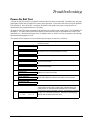
Power-On Self Test .......................................................................................................................................45
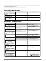
Power-On Troubleshooting ...........................................................................................................................46
Print Engine Troubleshooting .......................................................................................................................46
Print Engine Self Tests ..................................................................................................................................50
Introduction ..............................................................................................................................................50
CANCEL Key Self Test...........................................................................................................................50
PAUSE Key Self Test ..............................................................................................................................51
FEED Key Self Test.................................................................................................................................52
FEED Key and PAUSE Key Self Test.....................................................................................................53
Communications Diagnostics Test...........................................................................................................54
%®ÏÆ ³³³³³³³³³³³³³³³³³³³³³³³³³³³³³³³³³³³³³³³³³³³³³³³³³³³³³³³³³³³³³³³³³³³³³³³³³³³³³³³³³³³³³³³³³³³ {{
Single In-line Memory Module (SIMM).......................................................................................................55
Personal Computer Memory Card Interface Association (PCMCIA) Memory Card ...................................55
ZebraNet™ PrintServer II .............................................................................................................................55
Remote Front Panel .......................................................................................................................................55
-ÃÏÍlÍ0®lYyYAÏÆ ³³³³³³³³³³³³³³³³³³³³³³³³³³³³³³³³³³³³³³³³³³³³³³³³³³³³³³³³³³³ {Ê
Standard Features ..........................................................................................................................................57
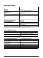
Physical Characteristics.................................................................................................................................57
Environmental Operating Range ...................................................................................................................57
Printing Considerations .................................................................................................................................57
Media Specifications .....................................................................................................................................58
Ribbon Specifications....................................................................................................................................58
Zebra Programming Language (ZPL II)........................................................................................................58
Bar Codes ......................................................................................................................................................59
Communications Specifications ....................................................................................................................59
Memory .........................................................................................................................................................59
Electrical........................................................................................................................................................59
Fuses ..............................................................................................................................................................59
AC Power Cord Requirements ......................................................................................................................60
AC Power Cord Specifications ................................................................................................................60
Power Fuse Replacement ..............................................................................................................................60
Shipping.........................................................................................................................................................61
:AÃÃAÏáÍyÃAϳ³³³³³³³³³³³³³³³³³³³³³³³³³³³³³³³³³³³³³³³³³³³³³³³³³³³³³³³³³³³³³³³³³³ ËÑ
?lOÃA Í YlÆlÍÃlllÏ ³³³³³³³³³³³³³³³³³³³³³³³³³³³³³³³³³³³³³³³³³³³³³³³³³³³³³³ Ë{
Zebra 116PAX3 User’s Guide
iv
®®lcàÍ ³³³³³³³³³³³³³³³³³³³³³³³³³³³³³³³³³³³³³³³³³³³³³³³³³³³³³³³³³³³³³³³³³³³³³³³³³³³³³³³³³³³³³ Ë
Print Engine Communications Interface Technical Information...................................................................69
System Considerations .............................................................................................................................69
Interface Considerations...........................................................................................................................69
RS-232/RS-422/RS-485 Serial Data Port......................................................................................................70
IEEE 1284 Bi-directional Parallel Data Port.................................................................................................73
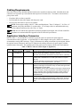
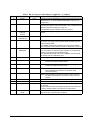
Cabling Requirements ...................................................................................................................................74
Applicator Interface Connector .....................................................................................................................74
®®lcàÍ ³³³³³³³³³³³³³³³³³³³³³³³³³³³³³³³³³³³³³³³³³³³³³³³³³³³³³³³³³³³³³³³³³³³³³³³³³³³³³³³³³³³³³ Ê
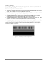
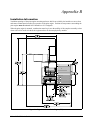
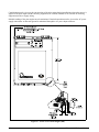
Installation Information .................................................................................................................................79
ÆÆAÃá ³³³³³³³³³³³³³³³³³³³³³³³³³³³³³³³³³³³³³³³³³³³³³³³³³³³³³³³³³³³³³³³³³³³³³³³³³³³³³³³³³³³³³³³³³ qÑ
clà³³³³³³³³³³³³³³³³³³³³³³³³³³³³³³³³³³³³³³³³³³³³³³³³³³³³³³³³³³³³³³³³³³³³³³³³³³³³³³³³³³³³³³³³³³³³³³³ qÊ
Zebra 116PAX3 User’s Guide
v
Zebra 116PAX3 User’s Guide
vi
ÏÃcØYÏ
Congratulations! You have just purchased a high-quality thermal demand print engine manufactured by the
industry leader in quality, service, and value. For over 30 years, Zebra Technologies Corporation has provided
customers the highest caliber of products and support.
To create and print label formats, refer to the ZPL II Programming Guide (part # 46530L). This guide is
available by contacting your distributor or Zebra Technologies Corporation. It is also available as a file to
download from Zebra’s Web site: http://support.zebra.com. In addition, label preparation software is
available. Contact your distributor or Zebra Technologies Corporation for further information.
The Zebra 116PAX3 Maintenance Manual (part # 43490L) contains the information you need to maintain the
print engine properly.
=HEUD3$;3ULQW(QJLQH
This user’s guide contains information specific to the 116PAX3 (600 dot/inch) print engine manufactured by
Zebra Technologies Corporation. The print engine is available in a right-hand configuration (media moves
from left to right) and in a left-hand configuration (media moves from right to left).
*HWWLQJ6WDUWHG
8QSDFNLQJ
Save the cartons and all packing materials in case shipping is required. If your print engine is equipped
with the factory-installed remote front panel option, the front panel, mounting bracket, hardware, and
instruction sheet are packaged in bubble wrap securely taped to the print engine. The interconnect cable is
secured to a cardboard panel inside the outer box.
Inspect all components for possible shipping damage:
•
Check all exterior surfaces for damage.
•
Raise the front cover and inspect for damage.
5HSRUWLQJ'DPDJH
If you discover shipping damage:
•
Immediately notify the shipping company and file a damage report.
•
Retain the carton and all packing material for inspection.
•
Notify your local Zebra distributor of the damage.
Zebra Technologies Corporation is not responsible for any damage incurred during shipment of the print
engine and will not cover the repair of this damage under its warranty policy. Any damage claim should be
filed with the shipping company.
For shipping information, refer to “Shipping” on page 61.
Zebra 116PAX3 User’s Guide
1
3ULQW(QJLQH0RXQWLQJ
For specific information on mounting the print engine into an applicator, refer to “Appendix B” on page 79.
&RPPXQLFDWLRQV
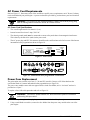
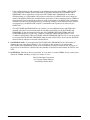
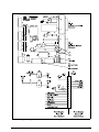
Refer to Figure 1 on page 4. The 116PAX3 print engine comes standard with both an Electronics Industries
Association (EIA) RS-232 serial interface (DB-25 Connector) and an IEEE 1284 bi-directional parallel
interface. The serial interface is also configured for both RS-422/RS-485 single drop and RS-485 multi-drop
serial interfaces. Any of these four interface methods may be used to send commands and label formats from a
host to the print engine.
A DB-15 Applicator Interface Connector provides communication between the print engine and the associated
applicator hardware. In some applications, control signal timing may be a critical element in the performance
of the print engine. Refer to “Appendix A” beginning on page 69 for control signal descriptions.
2
Zebra 116PAX3 User’s Guide
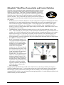
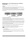
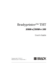
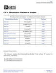
=HEUD/LQN5HDO7LPH&RQQHFWLYLW\DQG&RQWURO6ROXWLRQ
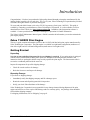
ZebraLink is the advanced print engine management tool that enables real-time,
remote error notification and systems control for OEMs, distributors, system
integrators, and end-users. ZebraLink’s combined components of WebView,
Alert, and ZBI help address the growing need for networked equipment. Only
ZebraLink gives you the power to control and monitor your print engines
anytime, anywhere. Every ZebraLink print engine (just look for the ZebraLink
logo), when used with ZebraLink-compatible network options, provides three
core features:
•
WebView (requires ZebraNet® PrintServer II) is the configuration component of ZebraLink, and enables
networked users to control multiple functions of the printing process using any standard Web browser,
such as Netscape Navigator or Internet Explorer. Users simply logon to the 116PAX3’s print engine
password-protected Web page via its IP address to view label formats, fonts, and graphics stored in
memory, as well as to adjust common print engine settings such as darkness, media/ribbon sensor values,
and applicator interface modes.
•
The Alert feature (requires ZebraNet® PrintServer II) gives 116PAX3 print engines the voice to “talk
back.” With ZebraLink, the print engines provide unsolicited communication to system administrators in
real time. If a 116PAX3 print engine runs out of media or ribbon, it instantly notifies the user by issuing a
detailed error message via e-mail to any text-capable, wired or wireless device, including pagers, cell
phones, PDAs, and PCs. Notification directly from the print engine ensures the proper personnel are
alerted immediately of an error condition so they can respond quickly and return the line to full operation.
•
With ZBI, users familiar with ANSI
BASIC programming language can
easily program advanced applications
within the 116PAX3’s print engine,
enabling it to accept and manipulate
information from nearly any data
source (PLCs, weigh scales,
scanners, etc.), as well as to print the
desired information on a label. Thus,
the 116PAX3 print engine acts as the
“brain” and creates true stand-alone
applications using a scanner,
keyboard, PLC, or weigh-scale as an
I/O device, replacing the need for a
dedicated computer terminal. ZBI
controls and interprets incoming text
and data streams, which permits the
replacement of any brand of bar code
print engines and printers with the
superior performance and reliability
of Zebra products, without costly
label reformatting.
ZebraLink Integration
Equipped with 4 MB of RAM and 1.5 MB of non-volatile memory, the 600 dpi 116PAX3 print engine is
capable of handling labels up to 33″ (84 cm) long and can store complex label formats, fonts, and graphics.
Print-and-apply systems with 116PAX3 print engines have the industry’s most advanced monitoring and
management tools available for any automated print-and-apply application. No other OEM print engines in the
market offer this powerful combination.
Zebra 116PAX3 User’s Guide
3
If your print engine is equipped with the factory-installed remote front panel option, a DB-15 connector is
supplied on the same bracket with the applicator interface for connection to the remote front panel.
NOTE: With the exception of the optional remote front panel, you must supply all interface cables for
your application. Refer to “Appendix A” beginning on page 69 for specific cable requirements.
CAUTION: Connecting a data communications cable while the power is ON may damage the
116PAX3 print engine.
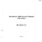
Refer to Figure 7 on page 12 and ensure that the AC power ON/OFF switch is in the OFF (O) position. Ensure
that power is off to the host and the applicator. Insert each connector fully and tighten all screws. When
connecting a parallel interface cable, secure the cable to the print engine with the two clips on the connector.
3ULQW(QJLQH3RZHU
The power supply in the 116PAX3 print engine automatically detects the applied line voltage and works in the
90 to 264 VAC, 48 to 62 Hz range.
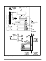
Refer to Figure 1. The AC power cord must have a three-prong female connector on one end that plugs into
the mating connector at the rear of the print engine. If a power cord was not included with your print engine,
refer to “Appendix A” beginning on page 69.
:$51,1*)RUSHUVRQQHODQGHTXLSPHQWVDIHW\DOZD\VXVHDWKUHHSURQJSOXJ
ZLWKDQHDUWKJURXQGFRQQHFWLRQWRWKH$&SRZHUVRXUFH
Refer to Figure 7 on page 12 and ensure that the AC power ON/OFF switch is in the OFF (O) position before
connecting the AC power cord to a nearby electrical outlet.
Figure 1. Power and Cable Connections
4
Zebra 116PAX3 User’s Guide
"lcAÍHÍ/OOÍ Ac
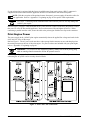
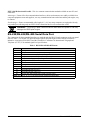
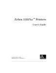
0HGLD/RDGLQJ
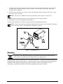
If your print engine is a right-hand unit (printed labels are presented on the right-hand side of the unit), refer to
Figure 2 while performing the following procedure. If your print engine is a left-hand configuration (printed
labels are presented on the left-hand side of the unit), refer to Figure 3.
1. Load the media on the media supply reel of the applicator (refer to the applicator’s user’s manual).
2. Grasp the outer media edge guide (A) and slide it as far out from the print engine frame as possible.
3. Open the printhead assembly (B) by unlatching the printhead latch (C) from the locking pin (D).
4. Press the release button (E) on the segmented pinch roller assembly (F) and allow the assembly to pivot up.
5. Thread the media under the upper guide post (G), between the rubber pinch roller and the associated roller
in the segmented pinch roller assembly (F), and under the printhead assembly (B) until approximately 30″
(75 cm) of media extends out of the print engine. Remove the labels from the exposed media.
Figure 2. Media Loading (RH)
Zebra 116PAX3 User’s Guide
5
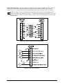
6. Ensure the media is aligned to the stationary inner media edge guide and the indicator on the peel bar.
7. Close the printhead assembly (B) by rotating the printhead latch (C) until it latches onto the locking
pin (D).
8. Press down on the pivoting segmented pinch roller assembly (F) until it locks closed.
9. Position the outer media edge guide (A) so it just touches the outer edge of the media.
10. Raise the peel roller latch (H) so the peel roller assembly (I) pivots down to a vertical position.
11. Thread the media liner around the peel bar (J), under the lower media liner roller (K), and through the peel
roller assembly (I). (See Detail.)
NOTE: If the applicator has an air tube, route the media liner between the air tube and the peel bar. Do
not thread the media liner over this tube!
12. Rotate the peel roller assembly (I) up until it locks into the closed position.
13. Thread the media liner under the lower guide post (L) and around the take-up spindle of the applicator
(refer to the applicator’s user’s manual).
Figure 3. Media Loading (LH)
6
Zebra 116PAX3 User’s Guide
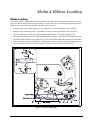
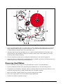
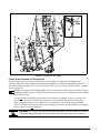
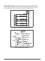
5LEERQ/RDGLQJ
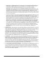
To load ribbon, refer to Figure 4 (for right-hand units) or Figure 5 (for left-hand units).
NOTE: Do not load ribbon if the print engine is to be used in the direct thermal mode.
CAUTION: When installing the ribbon roll on the ribbon supply spindle, ensure that it is fully
seated and that the ribbon is aligned squarely with its core. Do not use ribbon that is narrower
than the media. If the printhead is not protected by the smooth liner of the ribbon, premature
printhead failure may result due to excessive abrasion.
1. Install the ribbon roll onto the supply spindle (M) and push it on until it is fully seated, so the ribbon feeds
as shown in Figure 4 for right-hand units or Figure 5 for left-hand units. Ensure that the ribbon core fits
tightly to the spindle. If the core is not tight, proper ribbon tension may not be maintained.
2. Install an empty ribbon core onto the ribbon take-up spindle (N) and push it on until it is fully seated.
Ensure that the ribbon core fits tightly to the spindle.
3. Open the printhead assembly (B) by unlatching the printhead latch (C) from the locking pin (D).
4. Using your thumb and the side of your index finger, squeeze the ribbon supply dancer arm opening tab (O)
toward the outer U-shaped channel and pivot open the dancer arm. Carefully thread the ribbon between
the two U-shaped channels, and then slowly release the ribbon supply dancer arm.
5. Thread the ribbon under the printhead assembly (B) and then up toward the ribbon take-up dancer
assembly.
Figure 4. Ribbon Loading (RH)
Zebra 116PAX3 User’s Guide
7
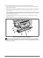
Figure 5. Ribbon Loading (LH)
6. Using your thumb and the side of your index finger, squeeze the dancer arm opening tab (P) toward the
inner U-shaped channel and pivot open the dancer arm. Carefully thread the ribbon between the two
U-shaped channels, and then slowly release the dancer arm.
7. Attach the ribbon to the take-up spindle core (use a label if needed) and wind for several turns in the
direction shown in the illustration. Make sure the ribbon winds evenly on the spindle to prevent the
possibility of the ribbon telescoping.
8. Close the printhead assembly (B) by pivoting the printhead latch (C) onto the locking pin (D).
9. Ensure the ribbon is routed properly in both ribbon dancer assemblies and between the ribbon sensor (Q)
and the ribbon sensor reflector (R) positioned below it.
5HPRYLQJ8VHG5LEERQ
To remove used ribbon, refer to Figure 4 (for right-hand units) or Figure 5 (for left-hand units):
1. Open the printhead assembly (B) by unlatching the printhead latch (C) from the locking pin (D).
2. If the ribbon is not completely exhausted, wind the remaining ribbon onto the take-up spindle (N), or cut
the ribbon between the take-up spindle and the ribbon take-up dancer assembly.
3. Remove the ribbon, complete with the core, from the ribbon take-up spindle.
4. Remove the supply ribbon core from the ribbon supply spindle (M).
5. Load the new ribbon as explained on page 7.
8
Zebra 116PAX3 User’s Guide
"lcAÍ0lÆÃÍ-ÆÏ
5HIOHFWLYH0HGLD6HQVRU
Some types of media have black marks printed on the underside of the media liner that act as “Start of Label”
indicators. The reflective media sensor senses these black marks. The position of this sensor is not adjustable.
If you use this type of media, refer to “Media Specifications” on page 58 for information about black mark
requirements.
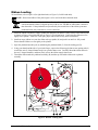
7UDQVPLVVLYH0HGLD6HQVRU
The transmissive media sensor finds “Start of Label” indicators such as a notch or hole in the media or an
interlabel gap between labels. This sensor consists of a light source (positioned below the media) and a light
sensor (positioned above the media). To position this sensor, refer to Figure 6. If the media has a notch or
hole, slide the sensor position indicator (Q) along the pivoting segmented pinch roller assembly (F) so the point
of the indicator aligns with the notch or hole in the media. If your media uses an interlabel gap, position the
media sensor approximately at the center of the media width.
Figure 6. Media Sensor Adjustment (RH)
Zebra 116PAX3 User’s Guide
9
10
Zebra 116PAX3 User’s Guide
-ÃÏÍlÍ%®lÃAÏ
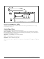
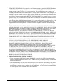
3RZHU2Q2II6ZLWFK
The Power On/Off Switch is located on the top of the print engine housing, as shown in Figure 7. When this
switch is placed in the ON ( | ) position, the POWER light turns ON and the print engine automatically
performs a Power-On Self Test (POST). The Liquid Crystal Display (LCD) validates the steps in the self test.
NOTE: Refer to “Troubleshooting” beginning on page 45 if the print engine stops due to failing a test
in the POST.
)URQW3DQHO.H\V
All controls for the print engine are located on the front panel. If your print engine is equipped with the
factory-installed remote front panel option, the front panel is absent from the front of the print engine and all
controls are located on the remote front panel.
Four keys are used to control the various print engine operations:
FEED Key—If you press the FEED key while the print engine is idle or paused, a blank label is fed
immediately. If you press the FEED key while the print engine is printing, one blank label is fed after the
completion of the current batch of labels. Once the blank label has been fed, pressing the FEED key again
feeds a second label.
PAUSE Key—The PAUSE key stops and restarts the printing process. When the print engine is paused, the
PAUSE light is ON. The first time you press the PAUSE key, any partially printed label is completed, then the
printing process is stopped. If the print engine is idle when you press the PAUSE key, no new print requests are
accepted. Press the PAUSE key a second time to resume the printing process.
The PAUSE mode can also be activated/deactivated through pin 5 of the Applicator Port or by sending a
ZPL II® command to the print engine.
CANCEL Key—The CANCEL key functions only when the print engine is paused. When you press the
CANCEL key, the label format that is currently printing is canceled. If no label format is printing, then the
next one to be printed is canceled. If there are no label formats stored in the print engine waiting to be printed,
the CANCEL key is ignored. To clear the print engine’s entire label format memory, press and hold this key
for several seconds until the DATA light turns OFF. The print engine discards all of the label format data it
has received and returns to the idle state.
.
CALIBRATE Key—The CALIBRATE key functions only in the PAUSE mode. Press once to recalibrate for
proper media length, set media type (continuous/non-continuous), and set print method (direct thermal/thermal
transfer).
Zebra 116PAX3 User’s Guide
11
Figure 7. Control Panel
/LTXLG&U\VWDO'LVSOD\/&'
The control panel shown in Figure 7 contains a backlit LCD. It shows operational status as well as setup
modes and feature parameters.
&RQWURO3DQHO.H\V
Five keys are used to set print and communication parameters:
BLACK OVAL KEYS—These two keys are used to change parameter values depending on the parameter
being displayed. Common uses include increasing or decreasing a value, answering yes or no, indicating ON
or OFF, and scrolling through several choices.
PREVIOUS—Scrolls the display to the previous parameter.
NEXT—Scrolls the display to the next parameter.
SETUP/EXIT—Enters and exits the setup mode.
Specific uses of these keys are explained with each parameter setting description in “Configuration” beginning
on page 15.
12
Zebra 116PAX3 User’s Guide
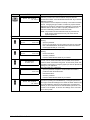
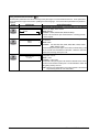
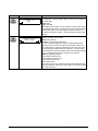
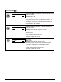
)URQW3DQHO,QGLFDWRU/LJKWV/('V
LEDs on the front panel are a quick indication of the print engine’s status.
LED
OFF
ON
FLASHING
POWER Print engine OFF or no
(Green) power to print engine.
PAUSE Normal operation.
(Yellow)
DATA
(Green)
MEDIA
(Yellow)
RIBBON
(Yellow)
ERROR
(Orange)
Power switch is ON and power is being
—
supplied to print engine.
Print engine is paused (Printhead, ribbon,
—
or paper error detected.
or
PAUSE key was pressed.
or
A pause was requested from the
Applicator Port.
or
A pause was received as part of the label
format).
No data being received Data processing or printing taking place. Print engine is receiving data from or
or processed.
sending status information to the host
computer. Flashing slows when the print
engine cannot accept more data, but
returns to normal once data is again being
received.
Normal operation.
Out of media. (Print engine is paused,
—
Media properly loaded. LCD displays error message, and PAUSE
light is ON).
Normal operation.
Ribbon in (print engine is in direct thermal
—
Ribbon properly loaded. mode) or no ribbon loaded (print engine is
in thermal transfer mode). Print engine is
paused, LCD displays error message, and
PAUSE light is ON.
No print engine errors.
—
Print engine error exists. Check LCD for
status.
Zebra 116PAX3 User’s Guide
13
14
Zebra 116PAX3 User’s Guide
yØÃAÏ
After you have installed the media and ribbon and the Power-On Self Test (POST) is complete, the LCD shows
“PRINTER READY.” (If the print engine fails its POST, refer to page 45.) You may now set print engine
parameters for your application using the front panel display and the five keys directly below it.
NOTE: Print engines that are operating on an IP network can be quickly configured using ZebraNet®
WebView (optional ZebraNet® PrintServer II required). For information, refer to ZebraNet
Networking: PrintServer II Installation and User’s Guide.
If it becomes necessary to restore the initial print engine defaults, see “FEED Key and PAUSE Key Self Test”
on page 53.
(QWHULQJWKH6HWXS0RGH
To enter the setup mode, press the SETUP/EXIT key.
Press either the NEXT key or PREVIOUS key to scroll to the parameter you wish to set.
NOTE: You may also press and hold the NEXT and PREVIOUS keys to advance quickly through the
configuration parameters.
Parameters in this section are shown in the order displayed when pressing the NEXT key. Throughout this
process, press the NEXT key to continue to the next parameter, or press the PREVIOUS key to return to the
previous parameter in the cycle.
An asterisk (*) in the upper left-hand corner of the LCD indicates that the value displayed is different from the
currently stored value.
&KDQJLQJ3DVVZRUG3URWHFWHG3DUDPHWHUV
Certain parameters, indicated by an illustration of a key
default.
after the title, are password protected by factory
CAUTION: Do not change password-protected parameters unless you have a complete
understanding of what you are doing! If the parameters are set incorrectly, they could cause the
print engine to function in an unpredictable way.
The first attempt to change one of these parameters (pressing one of the BLACK OVAL keys) requires you to
enter a four-digit password. This is done via the “ENTER PASSWORD” display.
ENTER PASSWORD
0000
+
The LEFT BLACK OVAL key changes the selected digit positions, and the RIGHT BLACK OVAL key
increases the selected digit value. After entering the password, press the NEXT key. The parameter you wish
to change is displayed. If the password was entered correctly, you can now change the value.
The default password value is 1234. The password can be changed using the ^KP (Define Password) ZPL II
instruction or through ZebraNet® WebView (optional ZebraNet® PrintServer II required).
Zebra 116PAX3 User’s Guide
15
NOTE: Once the password has been entered correctly, it does not have to be entered again unless you
leave and re-enter the setup mode using the SETUP/EXIT key.
NOTE: You can disable the password protection feature so that it no longer prompts you for a
password by setting the password to ØØØØ using the ^KPØ ZPL/ZPL II command. To re-enable the
password-protection feature, send the ZPL/ZPL II command ^KPx, where “x” can be any number, one
to four digits in length, except Ø.
/HDYLQJWKH6HWXS0RGH
You can leave the setup mode at any time by pressing the SETUP/EXIT key. The “SAVE CHANGES” display
appears.
SAVE CHANGES
PERMANENT
There are five choices described below. Pressing the LEFT or RIGHT BLACK OVAL key displays other
choices, and pressing the NEXT key selects the displayed choice.
PERMANENT—Permanently saves the changes. Values are stored in the print engine even when power is
turned off.
TEMPORARY—Saves the new changes until they are changed again or until power is turned off.
CANCEL—Cancels all changes since pressing the SETUP/EXIT key except the darkness and tear-off settings
(if they were changed).
LOAD DEFAULTS—Loads factory defaults as the print engine’s operating parameters. The factory defaults
are shown on the following pages.
NOTE: Loading factory defaults requires that a new print engine calibration be performed, which
resets printhead resistance and applicator port values.
LOAD LAST SAVE—Reloads values from the last permanent save as the print engine’s operating parameters.
&RQILJXUDWLRQDQG&DOLEUDWLRQ6HTXHQFH
The configuration parameters are shown in the order they are displayed when the NEXT key is pressed. Press
the NEXT key to move to the next parameter or the PREVIOUS key to return to the previous parameter in the
cycle. When a parameter is changed, an asterisk (*) is shown in the upper left corner of the LCD to indicate
that the value is different from the one currently active in the print engine.
If you want the prompts shown in a language other than English, press the PREVIOUS key to select the desired
language. Exit the setup mode, save permanent, and re-enter the setup mode. The LCD now uses the selected
language.
16
Zebra 116PAX3 User’s Guide
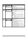
6HWWLQJ3ULQW3DUDPHWHUV
Press
LCD Shows
Action/Explanation
—
Normal print engine operation.
PRINTER READY
Setting Print Parameters
DARKNESS
-
4.0
+
TEAR OFF
-
+0
+
PRINT MODE
APPLICATOR
Zebra 116PAX3 User’s Guide
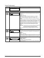
Adjusting Print Darkness: Press the RIGHT BLACK OVAL key to
increase darkness. Press the LEFT BLACK OVAL key to decrease
darkness.
Default: 4.0
Range: 0.0 to +30.0
Darkness (burn duration) settings are dependent on a variety of
factors, including ribbon type, media, and the condition of the
printhead. You may adjust the darkness for consistent high-quality
printing.
If printing is too light, or if there are voids in printed areas, you should
increase the darkness. If printing is too dark, or if there is spreading or
bleeding of printed areas, you should decrease the darkness.
The FEED Key Self Test on page 52 also can be used to determine the
best darkness setting. Since the darkness setting takes effect
immediately, you can see the results on labels that are currently
printing.
CAUTION: Set the darkness to the lowest setting that provides good
print quality. Darkness set too high may cause ink
smearing and/or it may burn through the ribbon.
Darkness settings also may be changed by the driver or software
settings.
Adjusting the Tear-Off Position: Press the RIGHT BLACK OVAL key
to increase the value; press the LEFT BLACK OVAL key to decrease
the value. Each press of the key adjusts the tear-off position by four
dot rows.
Default: +0
Range: –120 to +120
This parameter establishes the position of the media over the tear-off/
peel-off bar after printing so the label and liner can be torn off. Positive
numbers move the media out, negative numbers move the media in.
Selecting Print Mode: Press the RIGHT or LEFT BLACK OVAL key
to display other choices.
Default: Applicator
Selections: Tear-off, rewind, applicator
Print mode settings tell the print engine the method of media delivery
that you wish to use.
17
Press
LCD Shows
MEDIA TYPE
NON-CONTINUOUS
SENSOR TYPE
WEB
PRINT METHOD
THERMAL-TRANS.
18
Action/Explanation
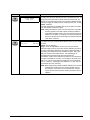
Setting Media Type: Press the RIGHT or LEFT BLACK OVAL key to
display other choices.
Default: Non-continuous
Selections: Continuous, non-continuous
This parameter tells the print engine the type of media you are using.
Selecting continuous media requires that you include a label length
instruction in your label format (^LLxxxx if you are using ZPL or
ZPL II).
When non-continuous media is selected, the print engine feeds media
to calculate label length (the distance between two detections of the
inter-label gap, webbing, or alignment notch or hole).
Setting the Sensor Type: Press the RIGHT or LEFT BLACK OVAL
key to display other choices.
Default: Web
Selections: Web, mark
This parameter tells the print engine whether you are using media with
a web (gap/space between labels, notch, or hole) to indicate the
separations between labels or if you are using media with a black mark
printed on the back. If your media does not have black marks on the
back, leave your print engine at the default (web).
Selecting Print Method: Press the RIGHT BLACK OVAL key for the
next value; press the LEFT BLACK OVAL key for the previous value.
Default: Thermal transfer
Selections: Thermal transfer, direct thermal
The print method parameter tells the print engine the method of printing
you wish to use: direct thermal (no ribbon) or thermal transfer (using
thermal transfer media and ribbon).
NOTE: Selecting direct thermal when using thermal transfer media
and ribbon creates a warning condition, but printing continues.
Verify that the ribbon is correctly installed for Thermal Transfer,
and not installed for Direct Thermal.
Zebra 116PAX3 User’s Guide
Press
LCD Shows
PRINT WIDTH
1920 dots
Action/Explanation
+
MAXIMUM LENGTH
-33.0 IN
838 MM+
Zebra 116PAX3 User’s Guide
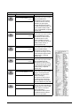
Setting Print Width: Press the RIGHT BLACK OVAL key to increase
the value; press the LEFT BLACK OVAL key to decrease the value. To
change the unit of measurement, press the LEFT BLACK OVAL key
until the unit of measurement is active, then press the RIGHT BLACK
OVAL key to toggle to a different unit of measure (inches, mm, or dots).
Default: 1920 dots
Print width determines the printable area across the width of the label
given the resolution of the print engine.
NOTE: Setting the width too narrow can result in portions of the label
not being printed on the label material. Setting the width too
wide wastes formatting memory and can cause printing off the
label and on the platen. This setting can affect the horizontal
position of the label format if the image was inverted using the
^POI ZPL II command.
Setting Maximum Label Length: Press the LEFT BLACK OVAL key
to decrease the value; press the RIGHT BLACK OVAL key to increase
the value.
Default: 33.0 in. (838 mm)
Range: Values are adjustable in one-inch (25.4 mm) increments.
Maximum length is used in conjunction with the calibration procedure.
The value of this setting determines the maximum label length that is
used during the media portion of the calibration process. Only a few
labels are required to set media sensors. The interlabel gap is
considered part of the label length and must be taken into
consideration. Always set the value that is closest to, but not less than,
the length of the label you are using. For example, if the length of the
label is 5 in. (126 mm) including the interlabel gap, set the parameter
for 6.0 in. (152 mm). If the length of the label is 7.5 in. (190 mm), set
the parameter for 9.0 in. (229 mm).
NOTE: Before beginning the media and ribbon calibration, be sure that
the Maximum Length is set one increment greater than the
actual media. If the value is set to a smaller value, the print
engine assumes that continuous media is loaded and cannot
calibrate.
19
Listing Print Engine Information
Press
LCD Shows
LIST FONTS
Action/Explanation
PRINT
LIST BAR CODES
PRINT
LIST IMAGES
LIST FORMATS
LIST SETUP
LIST ALL
20
PRINT
PRINT
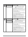
List Fonts: Press the RIGHT
BLACK OVAL key to print a label
listing all available fonts.
This selection is used to print a
label that lists all fonts currently
available in the print engine,
including standard print engine
fonts plus any optional fonts. Fonts
may be stored in RAM, FLASH
memory, font EPROMs, or optional
PCMCIA card.
List Bar Codes: Press the RIGHT
BLACK OVAL key to print a label
listing all available bar codes.
This selection is used to print a
label that lists all bar codes
currently available in the print
engine. Bar codes may be stored
in RAM, FLASH memory, or
optional PCMCIA card.
List Images: Press the RIGHT
BLACK OVAL key to print a label
listing all available images.
This selection is used to print a
label that lists all images currently
stored in the print engine’s RAM,
FLASH memory, or optional
PCMCIA card.
List Formats: Press the RIGHT
BLACK OVAL key to print a label
listing all available formats.
This selection is used to print a
label that lists all formats currently
stored in the print engine’s RAM,
FLASH memory, or optional
PCMCIA card.
List Setup: Press the RIGHT
BLACK OVAL key to print a label
listing the current print engine
configuration (as shown in the
sample on the right).
This selection is used to print a
label that lists the current print
engine configuration information.
(Same as CANCEL Key Self Test.)
List All: Press the RIGHT BLACK
OVAL key to print a label listing all
available fonts, bar codes, images,
formats, and the current print
engine configuration.
This selection is used to print a
label that lists the five previous
selections, as described.
Zebra 116PAX3 User’s Guide
Press
LCD Shows
Action/Explanation
INITIALIZE CARD
YES
Initialize Memory Card
CAUTION: Perform this operation only when it is necessary to erase
all previously stored information from the optional
PCMCIA card. Press the NEXT key to bypass this
function.
1. Press the RIGHT BLACK OVAL key to select “YES.”
If your print engine is set to require a password, you are prompted
to enter the password. Enter the password and press the NEXT
key.
2. The LCD shows “INITIALIZE CARD.” Press the RIGHT BLACK
OVAL key to select “YES.”
3. The LCD shows “ARE YOU SURE.”
4. Press the RIGHT BLACK OVAL key “YES” to begin initialization.
or
Press the LEFT BLACK OVAL key “NO” to cancel the request and
return to the “INITIALIZE CARD” prompt.
5. Press the SETUP/EXIT key followed by the NEXT key. If
initialization is still in process, the LCD flashes back and forth
between the two phrases “CHECKING B: MEMORY” and
“PRINTER IDLE.”
When initialization is complete, the print engine automatically exits
the setup mode and the LCD shows “PRINTER READY.”
NOTE: Depending on the amount of memory in the memory card,
initialization may take up to five minutes to complete.
INITIALIZE FLASH
YES
Initialize Flash Memory
CAUTION: Perform this operation only when it is necessary to erase
all previously stored information from the FLASH memory.
Press the NEXT key to bypass this function.
1. Press the RIGHT BLACK OVAL key to select “YES.”
If your print engine is set to require a password, you are prompted
to enter the password. Enter the password and press the NEXT
key.
2. The LCD shows “INITIALIZE FLASH.” Press the RIGHT BLACK
OVAL key to select “YES.”
3. The LCD shows “ARE YOU SURE.”
4. Press the RIGHT BLACK OVAL key “YES” to begin initialization.
or
Press the LEFT BLACK OVAL key “NO” to cancel the request and
return to the “INITIALIZE FLASH” prompt.
5. Press the SETUP/EXIT key followed by the NEXT key. If
initialization is still in process, the LCD flashes back and forth
between the two phrases “CHECKING E: MEMORY” and
“PRINTER IDLE.”
When initialization is complete, the print engine automatically exits
the setup mode and the LCD shows “PRINTER READY.”
NOTE: Depending on the amount of free FLASH memory, initialization
may take up to one minute to complete.
NO
ARE YOU SURE
Zebra 116PAX3 User’s Guide
YES
21
Media and Ribbon Sensor Calibration
NOTE: Before beginning this procedure, make sure that the media type has been configured, and that the maximum
length is set to a value equal to or greater than the length of the labels being used. If the maximum length is set to
a smaller value, the calibration process assumes that continuous media is in the print engine. See page 23 for
more information.
Perform this procedure when the print engine is first put into service. The calibration allows the print engine to establish
the proper settings for the specific media and ribbon used in your application.
There are two different types of calibration that can be performed by the print engine:
NOTE: The print engine must be paused before pressing the CALIBRATE key.
1) Standard Calibration:Press the CALIBRATE key on the print engine’s front panel. The print engine feeds media and
ribbon, and sets the values it detects for media, media liner (the gaps between labels), media out, and ribbon or no
ribbon (which determines the print mode—thermal transfer or direct thermal). This type of calibration also occurs as
part of the sensor profile and media and ribbon calibration procedures.
2) Media and Ribbon Sensor Sensitivity Calibration:Performing the media and ribbon calibration procedure resets the
sensitivity of the sensors to detect the media and ribbon you are using more easily. With the sensors at their new
sensitivity, the print engine then performs the standard calibration described above. Changing the type of ribbon and/or
media may require resetting the sensitivity of the media and ribbon sensors. Indications that the sensitivity may need to
be reset include a CHECK RIBBON light on with the ribbon properly installed or non-continuous media being treated as
continuous media.
Press
LCD Shows
Action/Explanation
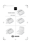
SENSOR PROFILE
PRINT
Sensor Profile: Press NEXT to skip this standard calibration
procedure and continue with the media and ribbon calibration
parameter that follows. Press the RIGHT BLACK OVAL key to initiate
this standard calibration procedure and print a media sensor profile.
See Figure 8. The media sensor profile may be used to troubleshoot
registration problems that may be caused when the media sensor
detects preprinted areas on the media or experiences difficulty in
determining web location. If the sensitivity of the media and/or ribbon
sensors MUST be adjusted, use the media and ribbon sensor
sensitivity procedure described on page 23.
Figure 8. Media Sensor Profile
22
Zebra 116PAX3 User’s Guide
Press
LCD Shows
MEDIA AND RIBBON
CALIBRATE
Action/Explanation
Media and Ribbon Sensor Sensitivity: Press NEXT to skip the
calibration procedure and continue with the host port selection
parameters that follow. Press the RIGHT BLACK OVAL key to start the
calibration procedure.
This procedure is used to adjust the sensitivity of the media and ribbon
sensors. Changing the type of ribbon or media may require that this
calibration be performed. Indications that calibration is necessary are
RIBBON LIGHT on when the ribbon is properly installed and noncontinuous media being treated as continuous media.
NOTE: The procedure must be followed exactly as presented. All
steps must be performed even if only one of the sensors
requires adjustment.
Media and Ribbon Calibration Procedure
LOAD BACKING
CANCEL
CONTINUE
REMOVE RIBBON
CANCEL
CONTINUE
CALIBRATING
PLEASE WAIT
—
RELOAD ALL
CONTINUE
MEDIA AND RIBBON
CALIBRATE
Zebra 116PAX3 User’s Guide
Press the LEFT BLACK OVAL key to cancel the operation, or do the
following:
1. Open the printhead.
2. Remove enough labels from the media roll so that only the media
liner is threaded between the media sensors when the media is
loaded (approximately 8″ or 203 mm).
Press the LEFT BLACK OVAL key to cancel the operation or do the
following:
1. Remove the ribbon.
2. Close the printhead.
3. Press the RIGHT BLACK OVAL key to continue.
The print engine automatically adjusts the scale (gain) of the signals it
receives from the media and ribbon sensors based on the specific
media and ribbon combination being used. On the sensor profile, this
essentially corresponds to moving the graph up or down to optimize the
readings for your application.
When “RELOAD ALL” is displayed:
1. Open the printhead and pull the media forward until a label is
positioned under the media sensor.
2. Reinstall the ribbon.
3. Close the printhead.
4. Press the RIGHT BLACK OVAL key to continue.
After scale is changed, the print engine performs a calibration
equivalent to pressing the CALIBRATE key. During this process, the
print engine checks the readings for the media and ribbon based on the
new scale established, determines the label length, and determines
whether you are in direct thermal or thermal transfer print mode. The
process is now complete! To see the new readings on the new scale,
print a sensor profile.
23
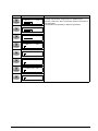
Setting Communication Parameters
Communication parameters must be set correctly for the print engine to communicate with the host. These parameters
ensure that the print engine and host are “speaking the same language.” All communication parameters are password
protected.
Press
LCD Shows
Action/Explanation
SERIAL COMM
RS232
24
-
BAUD
9600
+
-
DATA BITS
7 BITS
+
Setting Serial Communications: Press the RIGHT or LEFT BLACK
OVAL key to display other choices.
Default: RS232
Selections: RS232, RS422/485, RS485 multidrop
Select the communications port that matches the one being used by
the host computer.
Setting Baud: Press the RIGHT or LEFT BLACK OVAL key to display
other choices.
Default: 9600
Selections: 110, 300, 600, 1200, 2400, 4800, 9600, 14400, 19200,
28800, 38400, 57600
The baud setting of the print engine must match the baud setting of the
host for accurate communications to take place. Select the value that
matches the one being used by the host.
Setting Data Bits: Press the RIGHT or LEFT BLACK OVAL key to
display other choices.
Default: 7-bits
Selections: 7-bits, 8-bits
The data bits of the print engine must match the data bits of the host for
accurate communications to take place. Set the data bits to match the
setting being used by the host.
NOTE: Must be set to 8 data bits to use Code Page 850. See the ZPL
Programming Guide for more information.
Zebra 116PAX3 User’s Guide
Press
LCD Shows
PARITY
EVEN
STOP BITS
1, STOP BIT
HOST HANDSHAKE
XON/XOFF
PROTOCOL
NONE
Zebra 116PAX3 User’s Guide
Action/Explanation
+
+
Setting Parity: Press the RIGHT or LEFT BLACK OVAL key to display
other choices.
Default: Even
Selections: Even, odd, none
The parity of the print engine must match the parity of the host for
accurate communications to take place. Select the parity that matches
the one being used by the host.
Setting Stop Bits: Press the RIGHT or LEFT BLACK OVAL key to
display other choices.
Default: 1 stop bit
Selections: 1 stop bit, 2 stop bits
The stop bits of the print engine must match the stop bits of the host for
accurate communications to take place. Select the stop bits that match
the one being used by the host.
Setting Host Handshake: Press the RIGHT or LEFT BLACK OVAL
key to display other choices.
Default: XON/XOFF
Selections: XON/XOFF, DTR/DSR
The handshake protocol of the print engine must match the handshake
protocol of the host for communications to take place. Select the
handshake protocol that matches the one being used by the host.
Setting Protocol: Press the RIGHT or LEFT BLACK OVAL key to
display other choices.
Default: None
Selections: None, Zebra, ACK/NACK
Protocol is a type of error checking system. Depending on the
selection, an indicator may be sent from the print engine to the host
signifying that data has been received. Select the protocol that is
requested by the host. Details on protocol can be found in the ZPL II
Programming Guide Volumes I and II.
NOTE: Zebra is the same as ACK/NACK except that Zebra response
messages are sequenced.
NOTE: If Zebra is selected, print engine must use “DTR/DSR” host
handshake protocol.
25
Press
LCD Shows
NETWORK ID
000
COMMUNICATIONS
NORMAL MODE
26
Action/Explanation
+
Setting Network ID: Press the LEFT BLACK OVAL key to move to the
next digit position; press the RIGHT BLACK OVAL key to increase the
value of the digit.
Default: 000
Range: 000–999
Network ID is used to assign a unique number to a print engine used in
an RS-422/RS-485 network. This gives the host the means to address
a specific print engine. If the print engine is used in a network, you
must select a network ID number. This does not affect TCP/IP or IPX
networks.
Setting Communications Mode: Press the RIGHT or LEFT BLACK
OVAL key to display other choices.
Default: Normal mode
Selections: Normal mode, diagnostics
The communication diagnostics mode is a troubleshooting tool for
checking the interconnection between the print engine and the host.
When “diagnostics” is selected, all data sent from the host to the print
engine is printed as straight ASCII hex characters. The print engine
prints all characters received, including control codes, like CR (carriage
return). A sample printout is shown in Figure 16 on page 54.
NOTES on diagnostic printouts:
• FE indicates a framing error.
• OE indicates an overrun error.
• PE indicates a parity error.
• NE indicates noise.
If there are any errors, check that the communication parameters are
correct (see page 24). Set the print width equal to or less than the label
width used for the test.
Zebra 116PAX3 User’s Guide
Selecting Prefix and Delimiter Characters
Prefix and delimiter characters are 2-digit hex values used within the ZPL/ZPL II formats sent to the print engine. The print
engine uses the last prefix and delimiter characters sent to it, whether from a ZPL II instruction or from the front panel.
NOTE: DO NOT use the same hex value for the control, format, and delimiter character. The print engine needs to see
different characters to function properly.
Press
LCD Shows
Action/Explanation
CONTROL PREFIX
< >7EH
+
FORMAT PREFIX
<^>5EH
+
DELIMITER CHAR
<,>2CH
+
Zebra 116PAX3 User’s Guide
Control Prefix Character: Press the LEFT BLACK OVAL key to move
to the next digit position; press the RIGHT BLACK OVAL key to
increase the value of the digit.
Default: 7E (tilde—displayed as a black square)
Range: 00–FF
The print engine looks for this 2-digit hex character to indicate the start
of a ZPL/ZPL II control instruction.
NOTE: The “H” that is displayed indicates Hexadecimal and is not
entered as part of the value.
Format Prefix Character: Press the LEFT BLACK OVAL key to move
to the next digit position; press the RIGHT BLACK OVAL key to
increase the value of the digit.
Default: 5E (caret)
Range: 00–FF
The print engine looks for this 2-digit hex character to indicate the start
of a ZPL/ZPL II format instruction.
Delimiter Character: Press the LEFT BLACK OVAL key to move to
the next digit position; press the RIGHT BLACK OVAL key to increase
the value of the digit.
Default: 2C (comma)
Range: 00–FF
The delimiter character is a 2-digit hex value used as a parameter
place marker in ZPL/ZPL II format instructions. Refer to the ZPL II
Programming Guide Volume I for more information.
27
Selecting ZPL Mode
Press
LCD Shows
ZPL MODE
ZPL II
Action/Explanation
Selecting ZPL Mode: Press the RIGHT or LEFT BLACK OVAL key to
display other choices.
Default: ZPL II
Selections: ZPL II, ZPL
The print engine remains in the selected mode until it is changed by
this front panel instruction or by using a ZPL/ZPL II command. The
print engine accepts label formats written in either ZPL or ZPL II,
eliminating the need to rewrite any ZPL formats that already exist.
Refer to the ZPL II Programming Guide Volume II for information on the
differences between ZPL and ZPL II.
Power-Up and Head Close Parameters
MEDIA POWER UP
FEED
HEAD CLOSE
FEED
28
Media Power-Up: Press the RIGHT or LEFT BLACK OVAL key to
display other choices.
Default: Feed
Selections: Feed, calibration, length, and no motion
This parameter establishes the action of the media when the print
engine is turned on.
• Calibration: Recalibrates the media and ribbon sensors.
• Feed: Feeds the label to the first web.
• Length: Determines the length of the label.
• No Motion: Media does not move.
Head Close: Press the RIGHT or LEFT BLACK OVAL key to display
other choices.
Default: Feed
Selections: Feed, calibration, length, no motion
Determines the action of the media after the printhead has been
opened and then closed.
• Calibration: Recalibrates the media and ribbon sensors.
• Feed: Feeds the label to the first web.
• Length: Determines the length of the label.
• No Motion: Media does not move.
Zebra 116PAX3 User’s Guide
Label Positioning Parameters
Press
LCD Shows
Action/Explanation
BACKFEED
AFTER
LABEL TOP +000
-
LEFT POSITION
0000
Zebra 116PAX3 User’s Guide
+
+
Backfeed Sequence: Press the RIGHT or LEFT BLACK OVAL key to
display other choices.
Default: After
Selections: After, Before, Off
This parameter establishes when label backfeed occurs after a label is
removed in applicator mode. It has no effect in rewind mode. This
parameter setting can be superseded by the ~JS instruction when
received as part of a label format (refer to ZPL II Programming Guide
Volume I).
Adjusting Label Top Position: Press the RIGHT BLACK OVAL key
to increase the value; press the LEFT BLACK OVAL key to decrease
the value. The displayed value represents dots.
Default: +0
Range: –120 to +120 dot rows
The label top position adjusts the print position vertically on the label.
Positive numbers adjust the label top position further down the label
(away from the printhead); negative numbers adjust the position up the
label (toward the printhead).
Adjusting Left Position: Press the LEFT BLACK OVAL key to move
to the next position, press the RIGHT BLACK OVAL key to change
between + and – and to increase the value of the digit. The displayed
value represents dots.
Default: 0000
Range: –9999 to +9999
NOTE: For a negative value, enter the value before changing to the
minus sign.
This parameter establishes how far from the left edge of a label the
format begins to print by adjusting horizontal positioning on the label.
Positive numbers adjust the printing away from the main frame by the
number of dots selected; negative numbers shift printing toward the
main frame.
29
Press
LCD Shows
HEAD TEST COUNT
0000
+
HEAD RESISTOR
0500 OHMS
+
APPLICATOR PORT
OFF
30
Action/Explanation
Setting the Head Test Count: Press the LEFT BLACK OVAL key to
move the cursor, press the RIGHT BLACK OVAL key to change the
value of the digit.
Default: 0000 (disables the test)
Range: 0000–9999
The print engine periodically performs a test of the printhead
functionality, called a “printhead test” or “head test.” This parameter
establishes how many labels are printed between these internal tests.
Setting the Head Resistor Value: Press the LEFT BLACK OVAL key
to move to the next digit position; press the RIGHT BLACK OVAL key
to increase the value of the digit.
CAUTION: This parameter should be changed only by qualified
personnel!
Initial Value: Factory-set to match the printhead shipped with your
print engine.
Default Value: 0500
Range: 488 to 2415
This value has been pre-set at the factory to match the resistance
value of the printhead. It does not need to be changed unless the
printhead is replaced.
CAUTION: DO NOT set the value higher than that shown on the
printhead. Setting a higher value may damage the
printhead!
A label on the bottom of the printhead element shows the resistance
value (ohm value) for the printhead. Take note of the value before
installing the replacement printhead.
Setting the Applicator Port: Press the RIGHT or LEFT BLACK OVAL
key to display other choices.
Default: Off
Selections: Off, mode 1, mode 2, mode 3, mode 4
Determines how the print engine interfaces with the applicator.
• Off: The applicator port is off.
• Mode 1: Asserts the ~END_PRINT signal low while the print engine
is moving the label forward.
• Mode 2: Asserts the ~END_PRINT signal high while the print
engine is moving the label forward.
• Mode 3: Asserts the ~END_PRINT signal low for 20 milliseconds
when a label has been completed and positioned. Not asserted
during continuous printing modes.
• Mode 4: Asserts the ~END_PRINT signal high for 20 milliseconds
when a label has been completed and positioned. Not asserted
during continuous printing modes.
Zebra 116PAX3 User’s Guide
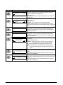
Printing Controls
Press
LCD Shows
START PRINT SIG
PULSE MODE
RESYNCH MODE
FEED MODE
Zebra 116PAX3 User’s Guide
Action/Explanation
Start Print Signal: Press the RIGHT or LEFT BLACK OVAL key to
display other choices.
Default: Pulse Mode
Selections: Pulse Mode, Level Mode
This parameter determines how the print engine reacts to the Start
Print Signal input on pin 3 of the applicator interface connector at the
rear of the print engine.
• In Pulse Mode, labels print when the signal transitions from HIGH to
LOW.
• In Level Mode, labels print as long as the signal is asserted LOW.
CAUTION: Start Print Signal is set by the applicator manufacturer and
should not be changed unless the factory defaults have
been reloaded. Please make a note of it! While other
choices are valid, the print engine must be returned to its
designated setting in order for it to work properly.
Resynch Mode: Press the RIGHT or LEFT BLACK OVAL key to
display other choices.
Default: Feed Mode
Selections: Feed Mode, Error Mode
This parameter determines how the print engine reacts if the label
synchronization is lost and the label top is not where expected.
FEED MODE—If the label top is not where expected, the print engine
feeds a blank label to find the label top position.
ERROR MODE—If the label top is not where expected, the print
engine stops, enters the PAUSED mode, displays the message “Error
Condition Feed Label”, flashes the ERROR LED, and asserts the
“Service Required” signal (pin 10 on the Applicator Interface
Connector).
To resynch the media to the top of the label in this mode, press the
PAUSE key to exit the PAUSED state. The ERROR LED stops flashing
and the “Service Required” signal is deactivated. The action of the
print engine is determined by the “Head Close” configuration selection:
• “Calibration”: the print engine feeds labels and recalibrates the
media sensors.
• “Feed”: the print engine feeds the labels to the next web.
• “Length”: the print engine feeds labels and calculates the label
length.
• “No Motion”: the media does not move. The user must press the
FEED key to cause the print engine to resynch to the start of the
next label.
31
Press
LCD Shows
RIBBON LOW MODE
25M
REPRINT MODE
DISABLED
32
Action/Explanation
Ribbon Low Mode: Press the RIGHT or LEFT BLACK OVAL key to
display other choices.
Default: 25M
Range: Off, 25M, 50M, 75M, 100M
When the Ribbon Low feature is off, the output signal (Pin 9) does not
function, the “Low Ribbon” warning is not displayed, and the print
engine continues to print until it runs out of ribbon.
When the Ribbon Low feature is set to any of the lengths, output signal
(Pin 9) on the applicator port is functional. When the amount of ribbon
on the supply spindle reaches the specific length, the output signal
asserts HIGH to provide a “Ribbon Low” warning.
Reprint Mode: Press the RIGHT or LEFT BLACK OVAL key to display
other choices.
Default: Disabled
Range: Enabled, Disabled
When the Reprint feature is enabled, the “Reprint” input signal (Pin 6)
on the applicator port is functional. When the input signal is asserted,
the last label printed is printed again. (This includes non-printing
labels.) Pressing the PAUSE key also prints the last label printed.
When the Reprint feature is disabled, the “Reprint” input signal is
ignored.
NOTE: The ^SP command is ignored when the Reprint feature is
enabled. When the Reprint feature is disabled, the ^SP
command can be used. In addition, when a received label
format is canceled prior to printing, the “reprint” function for the
previous label is also canceled. Refer to the ZPL II
Programming Guide for additional information.
Zebra 116PAX3 User’s Guide
Press
LCD Shows
-
-
-
-
-
-
-
-
WEB S.
073
MEDIA S.
075
RIBBON S.
071
MARK S.
000
MARK MED S. 000
MEDIA LED
082
RIBBON LED
008
MARK LED
005
Zebra 116PAX3 User’s Guide
Action/Explanation
+
These parameters are automatically set during the calibration
procedure and should be changed only by a qualified service
technician. Refer to the ZPL II Programming Guide for information on
these parameters.
Press the NEXT key repeatedly to skip these parameters.
+
+
+
+
+
+
+
33
Press
LCD Shows
LCD ADJUST
-
Action/Explanation
000
+
FORMAT CONVERT
NONE
XXX
XXX
RTS TAKEUP ARM
RTS Supply Dancer Arm Calibration Value: This parameter is used
as a diagnostic tool to monitor the voltage supplied to the Ribbon
Tensioning System Supply Dancer Arm. Refer to the Maintenance
Manual for information.
RTS SUPPLY ARM
IDLE DISPLAY
FW VERSION
34
LCD Adjustment: Press the LEFT BLACK OVAL key to decrease the
value (reduce brightness); press the RIGHT BLACK OVAL key to
increase the value (increase brightness).
Range: 00 to 19
This parameter allows you to adjust the brightness of your LCD if it is
difficult to read.
Format Convert: Press the RIGHT or LEFT BLACK OVAL key to
display other choices.
Default: None
Selections: None, 150-300, 150-600, 200-600, 300-600
Selects the bitmap scaling factor. The first number is the original
dots-per-inch (dpi) value; the second is the dpi to which you would like
to scale.
RTS Takeup Dancer Arm Calibration Value: This parameter is used
as a diagnostic tool to monitor the voltage supplied to the Ribbon
Tensioning System Takeup Dancer Arm. Refer to the Maintenance
Manual for information.
RTC DATE
01/31/01
+
RTC TIME
14:55
+
Idle Display: Press the RIGHT or LEFT BLACK OVAL key to display
other choices.
Default: Firmware version
Selections: mm/dd/yy (24 hour), mm/dd/yy (12 hour), dd/mm/yy
(24 hour), dd/mm/yy (12 hour), Firmware version
This parameter selects the LCD options for the real-time clock.
NOTE: If the default value is not selected, pressing either BLACK
OVAL key briefly displays the firmware version of the print
engine.
RTC Date: Press the LEFT BLACK OVAL key to move to the next digit
position; press the RIGHT BLACK OVAL key to increase the value of
the digit.
This parameter allows you to set the date following the convention
selected in “IDLE DISPLAY.”
RTC Time: Press the LEFT BLACK OVAL key to move to the next digit
position; press the RIGHT BLACK OVAL key to increase the value of
the digit.
This parameter allows you to set the time following the convention
selected in “IDLE DISPLAY.”
Zebra 116PAX3 User’s Guide
Press
LCD Shows
Action/Explanation
IP RESOLUTION
DYNAMIC
IP PROTOCOLS
ALL
IP ADDRESS
000.000.000.000
+
SUBNET MASK
000.000.000.000
+
DEFAULT GATEWAY
000.000.000.000
+
IP Resolution*: Press the RIGHT or LEFT BLACK OVAL key to
display other choices.
Default: Dynamic
Selections: Dynamic, permanent
Depending on the selection, allows either the user (“permanent”) or the
server (“dynamic”) to select the IP address. For more information, refer
to ZebraNet Networking: PrintServer II Installation and User’s Guide.
IP Protocols*: Press the RIGHT or LEFT BLACK OVAL key to display
other choices.
Default: All
Selections: All, gleaning only, RARP, BOOTP, DHCP, DHCP/BOOTP
If “dynamic” was chosen in the previous parameter, this selection
determines the method(s) by which the PrintServer II receives the IP
address from the server. For more information, refer to ZebraNet
Networking: PrintServer II Installation and User’s Guide.
IP Address*: Press the LEFT BLACK OVAL key to move to the next
digit position; press the RIGHT BLACK OVAL key to increase the value
of the digit.
This parameter selects the IP address if “permanent” was chosen in “IP
RESOLUTION.” (If “dynamic” was chosen, the user cannot select the
address.) For more information, refer to ZebraNet Networking:
PrintServer II Installation and User’s Guide.
Subnet Mask*: Press the RIGHT or LEFT BLACK OVAL key to
display other choices.
Default: Permanent (user must set)
Selections: Dynamic (user may set but server can assign), permanent
This parameter selects the part of the IP address that is considered to
be part of the local network. It can be reached without going through
the default gateway.
Default Gateway*: Press the LEFT BLACK OVAL key to move to the
next digit position; press the RIGHT BLACK OVAL key to increase the
value of the digit.
This parameter selects the IP address that the network traffic is routed
through if the destination address is not part of the local network.
* ZebraNet® PrintServer II option required
Zebra 116PAX3 User’s Guide
35
Press
LCD Shows
Action/Explanation
Selecting the Display Language: Press the RIGHT or LEFT BLACK
OVAL key to display other choices.
Default: English
Selections: English, Spanish, French, German, Italian, Norwegian,
Portuguese, Swedish, Danish, Spanish 2, Dutch, Finnish,
Japanese, Custom
This parameter allows you to change the language shown on the LCD.
You have now completed the entire configuration and calibration sequence. You may press either the NEXT key or the
SETUP/EXIT key.
You are now back at the first parameter in the configuration sequence.
NOTE: If you pressed the NEXT key but are through programming the
DARKNESS
print engine configuration, you may press the SETUP/EXIT key
and continue with the “SAVE SETTINGS” function.
LANGUAGE
SAVE CHANGES
PERMANENT
p
PRINTER READY
36
Save Settings: Press the RIGHT or LEFT BLACK OVAL key to
display other choices.
Default: Permanent
Selections: Permanent, temporary, cancel, load defaults, load last
save
This display appears when you attempt to exit the setup mode.
• Permanent: Permanently saves the changes, even when print
engine power is turned off.
• Temporary: Saves the changes until changed again or until power is
turned off.
• Cancel: Cancels all changes since you entered the setup mode
except for darkness and tear-off position (if they were changed).
• Load defaults: Loads factory defaults.
NOTE: Loading factory defaults requires calibration.
• Load last save: Loads the values from the last permanent save.
Press the NEXT key to activate the displayed choice.
You have exited the configuration and calibration sequence and are
now ready for normal print engine operation.
Zebra 116PAX3 User’s Guide
AÃlÍHÍcØÆÏlÏÆ
&OHDQLQJ
CAUTION: Use only the cleaning agents indicated. Zebra Technologies Corporation will not
be responsible for damage caused by any other cleaning materials used on the 116PAX3 print
engine.
Table 1 provides a recommended cleaning schedule. Cleaning swabs saturated with 90% Isopropyl Alcohol
are available from your Zebra distributor as a Preventive Maintenance Kit (part # 47362M).
Table 1. Recommended Cleaning Schedule
AREA
See Figures 9 and 10 for parts locations.
Printhead (1)
Platen Roller (2)
Media Path
Transmissive Media Sensor (3)
Reflective Media Sensor (4)
Ribbon Sensor (Q, Figures 4 and 5 shown on
pages 7 and 8)
Ribbon Sensor Reflector (R, Figures 4 and 5
shown on pages 7 and 8)
Door-Open Sensor (5)
Peel Bar (6)
METHOD
Alcohol
Alcohol
Alcohol
Air blow/Vacuum
Air blow/Vacuum
Alcohol
INTERVAL
After every 450′ (150 m) of media.
After every roll of ribbon when printing in the
thermal transfer mode.
After every roll of media when printing in the direct
thermal mode.
Alcohol
Air blow/Vacuum
Alcohol
After every roll of media or more often if needed.
&OHDQLQJWKH([WHULRU
The exterior surfaces of the print engine may be cleaned with a lint-free cloth. Do not use harsh or abrasive
cleaning agents or solvents! If necessary, a mild detergent solution or desktop cleaner may be used sparingly.
&OHDQLQJWKH,QWHULRU
Remove any accumulated dirt and lint from the interior of the print engine using a soft bristle brush and/or
vacuum cleaner. This area should be inspected every time a new ribbon is loaded.
&OHDQLQJWKH6HQVRUV
To ensure proper operation of the print engine, all sensors should be cleaned on a regular basis. To locate the
position of the media and door-open sensors, refer to Figure 9. Refer to Figure 4 on page 7 and Figure 5 on
page 8 for the ribbon sensor and ribbon sensor reflector.
Zebra 116PAX3 User’s Guide
37
Figure 9. Sensor Locations (RH)
&OHDQLQJWKH3ULQWKHDGDQG3ODWHQ5ROOHU
Inconsistent print quality (such as voids in the bar code or graphics) or light print may indicate a dirty
printhead. Media movement problems may indicate a dirty platen. For optimum print quality, perform the
following cleaning procedure after every roll of media (or 150 meters) or when a “Clean Head Now” warning
appears on the LCD.
NOTES: If print quality has degraded and you have not changed to a different type of media or ribbon,
cleaning the printhead may solve the problem. It should not be necessary to change the darkness setting
or the toggle pressure.
You do not need to turn off the print engine before cleaning the printhead. If power is turned off, all
label formats and images, as well as any temporarily saved parameter settings stored in the print
engine’s internal memory, are lost. When power is turned back on, these items must be reloaded.
If power is removed from the print engine when cleaning the printhead, the “Clean Head Now” warning
shown on the LCD will not disappear.
:$51,1*$QLPSURSHUO\VHDWHGSULQWKHDGGDWDFDEOHRUSRZHUFDEOHFRXOGUHVXOW
LQWKHSULQWKHDGJHQHUDWLQJH[FHVVLYHKHDWWKDWFRXOGFDXVHKDUPLILWLVWRXFKHG
38
Zebra 116PAX3 User’s Guide
To clean the printhead and platen roller, refer to Figure 10 and perform the following steps:
1. Open the printhead assembly (B) by lifting the printhead latch (C) upward away from the locking pin (D).
Remove the media and ribbon.
2. Brush, vacuum, or air blow any accumulated lint and paper dust away from the rollers. It is good practice
to clean the media, ribbon, and door-open sensors at this time. See Figure 9, Figure 4 on page 7, and
Figure 5 on page 8.
3. Use a cleaning swab saturated with alcohol to wipe the print elements from end to end. The print elements
form the grayish/black strip (1) just behind the chrome strip on the underside of the printhead. Allow a few
seconds for the solvent to evaporate.
4. Use a lint-free cloth moistened with alcohol to clean the platen roller (2) and other rollers. Rotate the
rollers while cleaning.
5. Reload the ribbon and/or media, latch the printhead, and continue printing.
Figure 10. Printhead and Platen Roller Cleaning (RH)
NOTE: If print quality has not improved, try cleaning the printhead with Save-a-Printhead cleaning
film. This specially coated material removes contamination buildup without damaging the printhead.
Call your authorized Zebra distributor to order the Save-a-Printhead cleaning kit for the 116PAX3 print
engine (part # 46902M).
Zebra 116PAX3 User’s Guide
39
([WHQGWKH/LIHRI<RXU3ULQWKHDGZLWK6DYHD3ULQWKHDG
&OHDQLQJ)LOP
(Recommended for all Zebra print engines—especially 600 dpi print engines).
&KDOOHQJH
The printhead is the most critical component in your print engine, and possibly the most delicate. It is a
consumable item just like the brakes on your car, which eventually wear over time. However, with ongoing
careful attention and maintenance, you can extend the life of the printhead.
Figure 11 shows photographs of three printheads. The first printhead is brand new. The second has printed
over 1 million linear inches of thermal transfer labels and has been properly maintained. The third printhead
has printed far fewer labels, but without proper care and maintenance, signs of abrasion and contamination
buildup are evident.
Figure 11. Effects of Printhead Maintenance
3ULQWKHDG3UHYHQWLYH0DLQWHQDQFH
For optimum performance, clean the printhead regularly after every roll of media (or 150 meters) or when a
“Clean Head Now” warning appears on the LCD. Take care when handling or cleaning the printhead by
removing any jewelry that may scratch the printhead and use a grounding strap or anti-static mat to discharge
static electricity that could damage the printhead.
To start, use only the pre-soaked (isopropyl alcohol) cleaning swabs provided in the preventive maintenance
kit. First, open the media cover to access the printhead, then open the printhead. Lightly blow or brush away
any loose dust and lint particles within the print mechanism (i.e., rollers, media/ribbon sensors, and printhead).
NEVER use any hard, metallic, or abrasive objects—such as a screwdriver—to remove adhesives or other
contaminants that may have built up on the printhead.
Next, press the swab tip against the printhead and swipe the print elements from end to end. Then, turn the
platen rollers while wiping them from side to side. Repeat this step until the swab no longer shows dirt.
$YRLGWKH&RQWULEXWLQJ)DFWRUVWR3UHPDWXUH3ULQWKHDG)DLOXUH
Abrasion: Over time, the movement of media/ribbon across the printhead wears through the protective
ceramic coating, exposing and eventually damaging the print elements (dots).
In order to avoid abrasion:
•
Clean your printhead frequently and use well-lubricated thermal transfer ribbons with backcoatings
optimized to reduce friction.
•
Minimize printhead pressure and burn temperature settings by optimizing the balance between the two.
•
Ensure that the thermal transfer ribbon is as wide or wider than the label media to prevent exposing the
elements to the more abrasive label material.
40
Zebra 116PAX3 User’s Guide
Ribbon Backcoating and Buildup: Printhead contamination from direct thermal media or thermal transfer
ribbon may occur in applications requiring high burn settings, high head pressure, high speed, or high volume.
This contamination builds up on the printhead elements, creating a barrier to the heat transformation required
to produce high-quality images. Contaminant buildup occurs gradually and results in poor print quality that
may look like faded print or failed print element(s). This buildup is very resistant to cleaning with the presoaked swabs and is difficult to remove.
In order to avoid ribbon backcoating and buildup:
•
Use thermal transfer ribbons that have been specially cured to provide backcoat protection for highdemand applications. These ribbons—sometimes referred to as anti-stick ribbons—also dissipate static
and provide more lubrication.
•
Follow the recommended Printhead Preventive Maintenance procedures.
•
Use Zebra’s Save-a-Printhead cleaning film to remove printhead contamination buildup quickly and
easily.
6DYHD3ULQWKHDG&OHDQLQJ)LOP
Save-a-Printhead cleaning film is a specially coated film that removes contamination buildup without
damaging the printhead.
Save-a-Printhead cleaning film extends the life of your printhead, reduces maintenance downtime and the cost
of replacing a printhead, and is an inexpensive, easy, and quick way to remove contaminants without having to
remove the printhead.
Use Save-a-Printhead cleaning film when you see degrading print quality that looks like faded print or a failed
print element(s) that cannot be corrected by cleaning with the pre-soaked cleaning swabs.
+RZWR8VH6DYHD3ULQWKHDG&OHDQLQJ)LOP
NOTE: If power is removed from the print engine when cleaning the printhead, the “Clean Head Now”
warning shown on the LCD will not disappear.
:$51,1*$QLPSURSHUO\VHDWHGSULQWKHDGGDWDFDEOHRUSRZHUFDEOHFRXOGUHVXOW
LQWKHSULQWKHDGJHQHUDWLQJH[FHVVLYHKHDWWKDWFRXOGFDXVHKDUPLILWLVWRXFKHG
1. Open the media cover.
2. Open the printhead, remove media and ribbon from the print mechanism.
3. Clean the printhead per the recommended Preventive Maintenance procedures.
4. Position the Save-a-Printhead film in the print path, placing the glossy side down away from the printhead
(matte side up).
5. Close and latch the printhead.
6. Slowly pull the full length of the film through the print mechanism.
7. Again, clean the printhead per the recommended Preventive Maintenance procedures.
8. Reload media and ribbon, close and latch the printhead.
9. Close the media cover.
10. Print labels and inspect for improved print quality. If quality has not improved, contact Zebra’s Technical
Support staff at 1.847.913.2259 or visit our Web site: http://www.zebra.com.
Zebra 116PAX3 User’s Guide
41
Only one pass of Save-a-Printhead film is required to remove contamination buildup, and each strip of film
can be used up to 10 times. Discard the strip when residue buildup or other contamination is apparent.
If a replacement printhead is needed, order one directly from Zebra to ensure that your print engine and
parts warranties remain intact and that the product performs optimally.
+RZWR2UGHU6DYHD3ULQWKHDG&OHDQLQJ)LOP.LWV
The kit contains three 10″ (25 cm) long strips of film. Call your authorized Zebra distributor to order the
Save-a-Printhead cleaning kit for the 116PAX3 print engine (part # 46902M).
7RJJOH3RVLWLRQLQJ
Proper toggle positioning is important for proper print quality. The toggle should be positioned approximately
midway across the width of the media.
To position the toggle, loosen the position locking nut (T, Figure 12) by rotating it clockwise. Slide the toggle
to the desired position, and tighten the locking nut by rotating it counterclockwise until it is just finger tight to
the toggle pivot shaft (X).
NOTE: Perform the Printhead Pressure Adjustment procedure on the next page if there is noticeable
bleed or swelling in the printed image (too much pressure) or if there are voids (too little pressure).
Figure 12. Printhead Pressure (Right-Hand Unit Shown)
42
Zebra 116PAX3 User’s Guide
3ULQWKHDG3UHVVXUH$GMXVWPHQW
If the darkness setting (burn duration) is set properly, but printing is too light or if the image shows signs of
bleeding or swelling, printhead pressure may need to be adjusted. Refer to Figure 12 to adjust printhead
pressure. As a starting point for adjustment, set the position of the adjusting nut (V) so that when the locking
nut (U) is tightened, it is approximately 0.4″ (10 mm) from the yoke (W). Use the lowest pressure possible that
provides the desired print quality.
1. Refer to “Configuration” beginning on page 15 and set the darkness value (burn duration) appropriately for
your media and ribbon.
2. Refer to the “PAUSE Key Self Test” on page 51 and print test labels.
3. Loosen the pressure adjustment locking nut (U) on the threaded shaft of the toggle assembly by rotating it
counterclockwise.
4. Rotate the adjusting nut (V) clockwise to increase or counterclockwise to decrease the spring pressure.
5. Print test labels and inspect for quality.
6. When print quality is acceptable, hold the adjusting nut (V) in position, and tighten the locking nut (U)
against it.
NOTE: Printhead and drive system (belts and bearings) life can be maximized by using the lowest
pressure that produces the desired print quality.
Zebra 116PAX3 User’s Guide
43
44
Zebra 116PAX3 User’s Guide
2ÃØOlÆÏ
3RZHU2Q6HOI7HVW
A Power-On Self Test (POST) is performed each time the print engine is turned ON. During this test, the front
panel lights (LEDs) turn ON and OFF to ensure proper operation. At the end of this self test, only the POWER
LED remains lit. Once the POST is complete, the media is advanced to the proper resting position, as
determined by the programmed Power-Up setting.
To initiate the POST, turn the print engine ON using the power switch on the control panel. The POWER LED
illuminates. The other control panel LEDs and the LCD monitor the progress and indicate the results of the
individual tests. All displayed prompts occur in English; however, when a test fails, the prompt cycles through
the international languages as well.
The normal self-test sequence occurs each time the print engine is turned on, as follows:
1.
All lights turn on simultaneously and then turn off in sequence through
the following steps.
SRAM functionality test performed.
2.
SRAM Test
3.
Option ROM Test
4.
Option ROM functionality test performed. The words “Not Installed”
are added to the LCD if optional ROM is not used.
Printhead is checked for proper operation.
Printhead Test
5.
Processor Test
Processor functionality test performed. The word “Failed” is added to
the LCD if the test fails.
E-Cubed Test
E-cubed functionality test performed. The word “Failed” is added to
the LCD if the test fails.
EEPROM Test
EEPROM/PROM functionality test performed. The word “Failed” is
added to the LCD if the test fails.
Memory Card Test
Optional PCMCIA Memory Card functionality test performed. The
words “Not Installed” are added to the LCD if no card is present.
6.
7.
8.
9.
Optional Flash Memory Card functionality test performed.
Flash Memory Test
10.
11.
PRINTER READY
x.x.MB
VXX.X.X
Zebra 116PAX3 User’s Guide
Depending on how the ^MF (Media Feed) instruction is set, the print
engine feeds to the first web or label length, calibrates ribbon and
media sensors, or sets label length and feeds one or more labels.
Print engine is ready for operation. Refer to “Configuration” beginning
on page 15 to set specific parameters. Designate prompt language
with the ^KL command or from the menu.
45
The following tables provide symptoms, a diagnosis of specific causes, and a recommended action that should
result in proper print engine operation.
If you need technical assistance, contact your equipment supplier.
3RZHU2Q7URXEOHVKRRWLQJ
SYMPTOM
DIAGNOSIS
All lights on, but nothing displays Internal electronic or firmware failure.
on the LCD, and the print engine
locks up.
Print engine locks up while running Main Logic Board failure.
the Power-On Self Test.
EEPROM checksum is
EEPROM TEST
incorrect.
ACTION
Call a service technician.
Call a service technician.
Call a service technician.
FAILED
3ULQW(QJLQH7URXEOHVKRRWLQJ
SYMPTOM
DIAGNOSIS
ERROR CONDITION
RIBBON OUT
For Thermal Transfer:
Ribbon not loaded or incorrectly loaded.
or
Ribbon sensor not detecting ribbon that
is loaded incorrectly.
Load ribbon correctly. See “Ribbon
Loading” on page 7.
Perform “Media and Ribbon Sensor
Calibration” on page 22.
For Direct Thermal:
Ribbon is loaded.
or
Media blocking the Ribbon Sensor.
Remove ribbon. Load media correctly.
Perform “Media and Ribbon Sensor
Calibration” on page 22.
Print engine stops; RIBBON light
ON, ERROR light flashes.
WARNING
RIBBON IN
ACTION
RIBBON light ON, ERROR light
flashes.
ERROR CONDITION
PAPER OUT
Print engine stops; MEDIA light
ON, ERROR light flashes.
ERROR CONDITION
HEAD OPEN
No media loaded or incorrectly loaded. Load media correctly. See “Media
Loading” on page 5.
Misadjusted Media Sensor.
Check position of the Media Sensor.
Print engine set for non-continuous
Install proper media or reset print
media, but continuous media is loaded. engine for current media type and
perform calibration.
Printhead is not fully closed.
Close printhead completely.
Head Open Sensor not working
Call a service technician.
properly.
Print engine stops and ERROR
light flashes.
WARNING
HEAD TOO HOT
Printhead overheated.
Allow print engine to cool. Printing
resumes when the printhead elements
cool to operating temperature.
Printhead requires cleaning.
See page 38 and clean the printhead.
Print engine stops and ERROR
light flashes.
WARNING
CLEAN HEAD NOW
Front panel LCD text alternates
between “Clean Head Now”
warning and idle display value.
46
NOTE: Do not turn off the print engine
while cleaning the printhead.
The “Clean Head Now” warning
will not disappear from the LCD
if the print engine is turned off.
Zebra 116PAX3 User’s Guide
3ULQW(QJLQH7URXEOHVKRRWLQJFRQWLQXHG
SYMPTOM
DIAGNOSIS
ACTION
Print engine stops and PAUSE
Not enough memory to perform function You may do any of the following:
light goes ON. The LCD displays: shown on the second line.
Explanation of errors:
OUT OF MEMORY
CREATING BITMAP
OUT OF MEMORY
STORING BITMAP
OUT OF MEMORY
BUILDING FORMAT
OUT OF MEMORY
STORING FORMAT
OUT OF MEMORY
STORING GRAPHIC
OUT OF MEMORY
STORING FONT
Long tracks of missing print on
several labels.
Fine, angular gray lines on blank
labels.
Wrinkled ribbon.
1. Creating Bitmap—Bitmap size
(label length/width) does not fit in
available memory.
2. Storing Bitmap—Not enough
memory available to store the bitmap
created.
A. With PAUSE on, send a ~HM
command to the print engine to
display the amount of free memory.
Then either:
3. Building Format—Label is too
complex.
Redesign graphic/format to fit
available memory or remove items
from memory to create more space.
or
4. Storing Format—Format is too large
to fit in available memory.
Press PAUSE to skip the formatting
step in process and proceed to the
next step.
B. With PAUSE on, press CANCEL.
The print engine skips the current
5. Storing Graphic—Graphic image is
label formatting process and goes
too large to fit in available memory.
to the next label.
6. Storing Font—Not enough memory C. Turn power OFF and then ON to
clear print engine memory and start
available to store the font.
over.
D. Upgrade the print engine to a larger
memory size.
Wrinkled ribbon.
See “Wrinkled Ribbon” in this table.
Print element damaged.
Call a service technician.
One or more of the printhead elements If the failed elements impact your
has failed the printhead element test.
printing application, replace the
printhead. To override this error,
disable the head test count feature on
the front panel by defaulting the value
to “0000.” See page 30.
Wrinkled ribbon.
See “Wrinkled Ribbon” in this table.
Ribbon fed through the machine
incorrectly.
Incorrect burn temperature.
See “Ribbon Loading” on page 7.
Set the burn temperature to the lowest
possible setting for good print quality.
Incorrect or uneven pressure.
Set the pressure to the minimum
needed for good print quality. See
“Printhead Pressure Adjustment” on
page 43.
Media not feeding properly; “walking”
Make sure that media is snug by
from side to side.
adjusting the media guide, or call a
service technician.
Strip plate needs adjusting.
Call a service technician.
Printhead needs vertical adjustment.
Call a service technician.
Printhead and Platen Roller need to be Call a service technician.
realigned.
Zebra 116PAX3 User’s Guide
47
3ULQW(QJLQH7URXEOHVKRRWLQJFRQWLQXHG
SYMPTOM
Broken or melted ribbon.
DIAGNOSIS
ACTION
Reduce setting for best print quality,
and clean the printhead thoroughly.
Ribbon tension dancer(s) oscillate Ribbon core is not standard size and is Replace ribbon with one that has a
erratically.
slipping on the spindle.
standard core size.
Light printing or no printing on the Printhead pressure needs adjustment, See “Toggle Positioning” on page 42
left or right side of the label.
printhead out of alignment, or toggle in and “Printhead Pressure Adjustment”
incorrect position.
on page 43.
Call a service technician.
Printing too light or too dark over Media or ribbon is not designed for
Replace supplies with those
the entire label.
high-speed operation.
recommended for high-speed
operation.
Incorrect or uneven printhead pressure. Set the pressure to the minimum
needed. See “Printhead Pressure
Adjustment” on page 43.
Smudge marks on labels.
Media or ribbon not designed for high- Replace supplies with those
speed operation.
recommended for high-speed
operation.
Misregistration/skips labels.
Media Sensor not positioned correctly. Perform Media Sensor position
adjustment (see page 9).
Print engine not calibrated.
Recalibrate print engine.
Improper label format.
Use correct label format.
Misregistration and misprint of one Media Sensor is not positioned
Place Media Sensor in proper position
to three labels.
correctly.
(see page 9).
Platen dirty.
Clean platen (see page 38).
Media does not meet specifications.
Use media that meets specifications.
Vertical drift in top-of-form position. A plus or minus 4-6 dot row
First calibrate print engine, then use the
(approximately 0.5 mm) vertical drift is “Label Top Position” setting to correct.
acceptable due to different tolerances See “Configuration and Calibration
of mechanical parts and print engine
Sequence” on page 16.
modes.
Print engine out of calibration.
Recalibrate print engine.
Platen dirty.
Clean platen (page 38).
Missing LCD characters or parts of LCD may need replacing.
Call a service technician.
characters.
Changes in parameter settings did Parameters are set incorrectly.
Set parameters and save permanently.
not take effect.
Cycle the print engine power OFF and
back ON.
A ZPL command has turned off the
Refer to the ZPL Programming Guide or
ability to change parameter.
call a service technician.
A ZPL command has changed the
Refer to the ZPL Programming Guide or
parameter back to the previous setting. call a service technician.
If problem continues, there may be a
Call a service technician.
problem with the main logic board.
48
Darkness setting too high.
Zebra 116PAX3 User’s Guide
3ULQW(QJLQH7URXEOHVKRRWLQJFRQWLQXHG
SYMPTOM
DIAGNOSIS
ZPL II was sent to the print engine, Communications parameters are
but not recognized.
incorrect.
DATA light always OFF.
or
DATA light always flashing.
Vertical image or label drift.
Zebra 116PAX3 User’s Guide
ACTION
Print a Communications Diagnostic
Label (see page 26). Check for format
or overrun errors. Reset
communication parameters (see
page 24).
Verify proper cable and replace if
necessary.
Set the characters in the print engine to
match ZPL II format. See “Selecting
Prefix and Delimiter Characters” on
page 27.
Incorrect Communications Cable in
use.
Prefix and delimiter characters set in
print engine do not match the ones
used in ZPL II format sent to the print
engine.
Incorrect/incomplete ZPL format sent to
If problem continues, check the ZPL II
the print engine.
format for changed ^CC, ^CT, and
^CD.
Print engine using non-continuous
Configure the print engine for nonlabels but configured in continuous
continuous and run calibration routine,
mode.
if necessary.
Incorrectly positioned media sensor.
Ensure the media sensor is properly
positioned to read a single/consistent
inter-label gap.
Improperly calibrated media sensor.
Perform “Media and Ribbon Sensor
Calibration” on page 22.
Platen dirty.
Clean platen (see page 38).
Improper printhead pressure settings
Adjust the printhead pressure to ensure
(toggles).
proper functionality (see page 43).
Improperly loaded ribbon or media.
Verify that the ribbon and media are
properly loaded (see pages 5–7).
Incompatible media.
Ensure the inter-label gaps or notches
are 2 mm–4 mm and consistently
placed. Media must not exceed
minimum specifications for mode of
operation.
49
3ULQW(QJLQH6HOI7HVWV
,QWURGXFWLRQ
These self tests, illustrated on the following pages, produce sample labels and provide specific information that
help determine the operating conditions for the print engine.
Each self test is enabled by pressing a specific front panel key or combination of keys while turning the power
switch ON. Keep the key pressed until the first indicator light turns OFF. The selected self test automatically
starts at the end of the POST.
NOTES: When performing these self tests, do not send data to the print engine from the host.
Full width media should be used when performing Print Engine Self Tests. If your media is not wide
enough, the test labels may print on the label and the platen roller, or in the case of narrow media, not
on the label at all. To prevent this from happening, check the configuration parameter “Setting the Print
Width” and ensure it is correct for the media you are using.
If your media is too short, the test label continues on the next label.
When canceling a self test prior to its actual completion, always reset the print engine by turning the
print engine power OFF and then ON.
If the print engine is in applicator mode and the liner is being taken up by the applicator, the operator
must manually remove the labels as they become available.
&$1&(/.H\6HOI7HVW
Press and hold the CANCEL key while turning the print engine
power ON. Release the key anytime after the first front panel
LED turns OFF.
This self test prints a label that contains a listing of the print
engine’s current configuration parameters stored in configuration
(EEPROM) memory (refer to Figure 13). To enable this test,
press the CANCEL key while turning the power switch ON.
The configuration may be changed either temporarily (for
specific label formats or ribbon and label stock) or permanently
(by saving the new parameters in EEPROM memory). Saving
new parameters occurs whenever a print engine calibration
procedure is performed. Refer to “Configuration and Calibration
Sequence” on page 16 for further details.
Figure 13. CANCEL Key Self Test
50
Zebra 116PAX3 User’s Guide
3$86(.H\6HOI7HVW
Press and hold the PAUSE key while turning the print engine power ON. Release the key anytime after the
first front panel LED turns OFF.
This self test comprises four individual test features:
1. The initial self test prints 15 labels at the slowest speed of print engine, then automatically pauses the print
engine. When the PAUSE key is pressed, an additional 15 labels print.
2. While the print engine is paused, alter the self test by pressing the CANCEL key once. When the PAUSE
key is pressed, the print engine prints 15 labels at 4″ (102 mm) per second.
3. While the print engine is paused, alter the self test a second time by pressing the CANCEL key once.
When the PAUSE key is pressed, the print engine prints 50 labels at the slowest speed.
4. While the print engine is paused, alter the self test a third time by pressing the CANCEL key once. When
the PAUSE key is pressed, the print engine prints 50 labels at 4″ (102 mm) per second.
5. While the print engine is paused, alter the self test a fourth time by pressing the CANCEL key once. When
the PAUSE key is pressed, the print engine prints 15 labels at the maximum speed of the print engine.
This self test can be used to provide the test labels required when making adjustments to the print engine’s
mechanical assemblies. See Figure 14.
Figure 14. PAUSE Key Self Test Sample Printout
Zebra 116PAX3 User’s Guide
51
)(('.H\6HOI7HVW
Press and hold the FEED key while turning the print engine power ON. Release the key any time after the first
front panel LED turns OFF.
NOTE: The CANCEL Key Self Test should be performed prior to this self test. Information on the
printed configuration label can be used with the results of this self test to determine the best darkness
setting for a specific media/ribbon combination.
Each label is printed at a different darkness setting, starting at three integer (whole number) settings below the
currently configured value and increasing until it is three settings darker than the configured value. The
relative darkness and speed are printed on each label. The bar codes on these labels can be ANSI-graded to
check print quality.
Compare these labels to determine which has the best print quality. Then add or subtract the value printed on
that label from the darkness value specified on the configuration label. The resulting numeric value (0.0 to
30.0) is the best darkness value for that specific media/ribbon combination. Use the front panel configuration
process to set the Print Darkness parameter to the new value. Refer to Figure 15 for an example of the label.
NOTE: The best print quality for certain media and ribbon combinations may be achieved by using a
darkness setting between whole numbers (for example, 7.8).
Figure 15. FEED Key Self Test
52
Zebra 116PAX3 User’s Guide
)(('.H\DQG3$86(.H\6HOI7HVW
Press and hold these two keys while turning the print engine power ON. The print engine configuration is
temporarily reset to the factory default values. These values remain active until power is turned OFF. If the
factory default values are permanently saved, a media calibration procedure must be performed. You
must also reset the head resistance value and the applicator port settings to their required values (see
“Configuration and Calibration Sequence” beginning on page 16).
The following chart indicates which print engine function controls each of the configuration parameters:
Parameter
Darkness
Tear Off
Print Mode
Media Type
Sensor Type
Print Method
Print Width
Label Length
Maximum Length
Host Port
Baud
Data Bits
Parity
Stop Bits
Host Handshake
Protocol
Network ID
Communications
Control Prefix
Format Prefix
Delimiter Character
ZPL Mode
Media Power Up
Head Close
Backfeed
Label Top
Left Position
Head Resistance
Applicator Port
Start Print Signal
Resynch Mode
Ribbon Low Mode
Reprint Mode
Web Sensor
Media Sensor
Ribbon Sensor
Mark Sensor
Mark Media Sensor
Media LED
Ribbon LED
Mark LED
Zebra 116PAX3 User’s Guide
Controlled by
Configuration, ZPL, and WebView
Configuration, ZPL, and WebView
Configuration, ZPL, and WebView
Calibration, Configuration, ZPL, and WebView
Configuration, ZPL, and WebView
Calibration, Configuration, ZPL, and WebView
Configuration, ZPL, and WebView
Calibration, Configuration, ZPL, and WebView
Configuration, WebView, and Memory Size
Configuration and WebView
Configuration, ZPL, and WebView
Configuration, ZPL, and WebView
Configuration, ZPL, and WebView
Configuration, ZPL, and WebView
Configuration, ZPL, and WebView
Configuration, ZPL, and WebView
Configuration, ZPL, and WebView
Configuration, ZPL, and WebView
Configuration, ZPL, and WebView
Configuration, ZPL, and WebView
Configuration, ZPL, and WebView
Configuration, ZPL, and WebView
Configuration, ZPL, and WebView
Configuration, ZPL, and WebView
Configuration, ZPL, and WebView
Configuration, ZPL, and WebView
Configuration, ZPL, and WebView
Configuration (must match head resistance label value), ZPL, and WebView
Configuration, ZPL, and WebView
Configuration, ZPL, and WebView
Configuration, ZPL, and WebView
Configuration, ZPL, and WebView
Configuration, ZPL, and WebView
Configuration, ZPL, and WebView
Configuration, ZPL, and WebView
Configuration, ZPL, and WebView
Configuration, ZPL, and WebView
Configuration, ZPL, and WebView
Configuration, ZPL, and WebView
Configuration, ZPL, and WebView
Configuration, ZPL, and WebView
53
Parameter
LCD Adjust
Modes Enabled
Modes Disabled
Resolution
Socket 1 ID
Firmware
Configuration
Memory
B:Memory
J12 Interface
J11 Interface
J10 Interface
J9 Interface
J8 Interface
J7 Interface
Controlled by
Configuration and WebView
ZPL and WebView
ZPL and WebView
Fixed (head type switch)
Fixed (option EPROMS)
Fixed (code EPROMS)
Configuration and WebView
Fixed (SIMM size and 1 MB standard)
Fixed (option card)
Fixed
Fixed
Fixed
Fixed
Fixed
Fixed
&RPPXQLFDWLRQV'LDJQRVWLFV7HVW
NOTE: The following test cannot be performed until all configuration and calibration parameters have
been set. For information, refer to “Configuration and Calibration Sequence” beginning on page 16.
This test is performed using the control panel. Refer to “Setting Communications Mode” on page 26. A
typical printout from this test is shown in Figure 16.
NOTE: This label is inverted when printed.
Figure 16. Results of Communications Diagnostics Test
54
Zebra 116PAX3 User’s Guide
%®ÏÆ
Your 116PAX3 print engine can be equipped with the following options. Contact your equipment supplier for
further information and pricing.
6LQJOH,QOLQH0HPRU\0RGXOH6,00
An optional 8 MByte SIMM increases the graphic and font storage capacity of the print engine and/or
increases the print length. As this is volatile memory, contents are lost when the print engine is turned off.
3HUVRQDO&RPSXWHU0HPRU\&DUG,QWHUIDFH$VVRFLDWLRQ
3&0&,$0HPRU\&DUG
The Type I or Type II PCMCIA memory card is used for graphic, font, and label format storage. This card is
an 8 MByte, non-volatile memory device, so the contents are not lost when the print engine is turned off.
=HEUD1HW3ULQW6HUYHU,,
Allows you to connect a Zebra print engine to your Ethernet network. Available for 10Base-T networks.
5HPRWH)URQW3DQHO
Allows you to operate from the remote front panel from as far away as 25′ (7 m). The Remote Front Panel is a
factory-installed option. When installed, the front panel is removed from the front of the print engine.
Zebra 116PAX3 User’s Guide
55
56
Zebra 116PAX3 User’s Guide
-ÃÏÍlÍ0®lYyYAÏÆ
6WDQGDUG)HDWXUHV
• Left-hand and right-hand models
• Thermal transfer and direct thermal printing
• 600 dpi (24 dpmm):
• Dual media sensors (transmissive is default)
Programmable constant printing speeds (per second) of:
1″ (25 mm), 2″ (51 mm), 3″ (76 mm), 4″ (102 mm)
• Full function Front Panel and multi-lingual backlit LCD;
• Real-time clock
180° rotatable
• Advanced counter with firmware support for printhead
• Thin glaze printhead with E3 Element Energy Control
cleaning
3K\VLFDO&KDUDFWHULVWLFV
Height
Width
Depth
Weight
11.8″ (300 mm)
9.6″ (244 mm)
17.8″ (452 mm)
34.5 lbs. (15.6 kg)
NOTE: For installation information, refer to “Appendix B” on page 79.
(QYLURQPHQWDO2SHUDWLQJ5DQJH
Operating Temperature
Thermal transfer
Direct thermal
Non-condensing relative humidity
Operation
Storage
Storage temperature
41° F to 104° F (5° C to 40° C)
32° F to 104° F (0° C to 40° C)
20% to 85%
5% to 85%
–40° F to 140° F (–40° C to 60° C)
3ULQWLQJ&RQVLGHUDWLRQV
Media Type
(continuous, die-cut, or black mark)
Resolution
Dot size
First dot location (from inside media edge)
Maximum print width
Maximum print length
(with full width media)
Non-continuous (4 MB Memory)
Non-continuous (12 MB Memory)
Continuous (4 MB Memory)
Continuous (12 MB Memory)
Zebra 116PAX3 User’s Guide
116PAX3
600 dots per inch
(24 dots per mm)
0.0016″ × 0.0016″
(0.035 mm × 0.070 mm)
0.093″ ± 0.035″ (2.4 mm ± 0.89 mm)
3.2″ (81.6 mm)
33″ (838 mm)
33″ (838 mm)
39″ (990 mm)
123″ (3124 mm)
57
0HGLD6SHFLILFDWLRQV
Media width (label and liner)
Minimum label length
Applicator mode
Rewind mode
Tear-off mode
Registration tolerance (does not include label/liner
position tolerances)
Vertical (concurrent labels)
Horizontal
Total thickness (including liner)
Interlabel Gap (Transmissive Sensor)
Minimum
Preferred
Maximum
Black Mark (Reflective Sensor)
Length (parallel to inside media edge)
Width (perpendicular to inside media edge)
Print Line to Peel Bar Distance
Media Unwind Force
Media Rewind Force
0.62″ to 4.5″ (13 mm to 114 mm)
0.5″ (12.7 mm); 0.25″ (6 mm) with backfeed off
0.25″ (6 mm)
0.5″ (12.7 mm); 0.25″ (6 mm) with backfeed off
≤±0.020″ (±0.5 mm) (in Applicator mode)
≤±0.020″ (±0.5 mm)
0.0058″ to 0.010″ (0.148 mm to 0.256 mm)
0.015″ (2 mm)
0.118″ (3 mm)
Refer to page 19 for Maximum Label Length discussion.
0.12″ to 0.43″ (3 mm to 11 mm)
≥0.43″ (≥11 mm)
0.464″ (11.8 mm)
Applicator media supply steady-state tension must be uniform and
must not exceed 2 lbs (1 kg). Start/Stop tension transients must not
exceed 4 lbs (1.8 kg).
Applicator media take-up pull tension must be uniform between
1 and 4 lbs (0.5 and 1.8 kg).
Media registration and minimum label length are affected by media type and width, ribbon type, and print speed. Performance improves
as these factors are optimized. Zebra recommends always qualifying any application with thorough testing.
5LEERQ6SHFLILFDWLRQV
Width (wound coated side out)
Standard length
Roll size
Inner core diameter/Maximum roll size
1.0″ to 4.5″ (25.4 mm to 114 mm)
2,952′ (900 m)
Note: Shorter lengths are accommodated.
1.0″ (25.4 mm)/4.2″ (107 mm)
=HEUD3URJUDPPLQJ/DQJXDJH=3/,,
• Communicates in printable ASCII characters
• Controlled via mainframe, mini, or PC
• Downloadable graphics, scalable and bitmap fonts, label
templates, and formats
• Object copying between memory areas (RAM and PC
memory card)
• Adjustable print cache
• Data compression
• Automatic memory allocation for “format while printing”
• Status messages to host upon request
58
• Format inversion (white on black)
• Mirror-image printing
• Four-position field rotation (normal—0°, 90°, 180°, 270°)
• Slew command
• Programmable label quantities with print and pause
control
• Automatic serialization of fields
• User-programmable password
Zebra 116PAX3 User’s Guide
%DU&RGHV
• Bar code modulus “X” dimensions:
— Picket fence (non-rotated) orientation:
0.0049″ mil to 0.049″
— Ladder (rotated) orientation:
0.0049″ mil to 0.049″
• Linear bar codes:
Code 11, Code 39, Code 93, Code 128 with subsets A/B C
and UCC Case Codes, ISBT-128, UPC-A, UPC-E, EAN-8,
EAN-13, UPC and EAN 2 or 5 digit extensions, Plessey,
Postnet, Standard 2 of 5, Industrial 2 of 5, Interleaved 2
of 5, LOGMARS, MSI, and Codabar
• Bar code ratios: 2:1, 7:3, 5:2, and 3:1
&RPPXQLFDWLRQV6SHFLILFDWLRQV
• Bi-Directional Centronics Parallel (36-pin connector) with IEEE 1284-compliant software protocol (standard)
• High-speed serial interfaces:
— Serial RS-232C w/DTR hardware handshake via DB-25 connector (standard)
— Serial RS-422/485 via 2 or 4-wire w/XON/XOFF handshake on alternate pins of DB-25 connector (standard)
— Configurable baud rates between 110 and 57.6K baud with 7 or 8 data bits, standard parity, 1 or 2 stop bits,
DTR/DSR, Xon/Xoff
— Fused +5 @ 500mA supplied at pin 9 of the DB-25 connector
• ZebraNet™ PrintServer II MPS Ethernet network print server—10Base-T (optional)
• Remote Front Panel interface with male DB-15S connector (factory-installed option)
• Applicator interface with female DB-15 connector
0HPRU\
• 4 MByte RAM standard
Optional 8 MByte SIMM Option available for longer labels or additional storage of fonts, graphics, logos, and label
formats.
• 4 MByte Resident Flash
• Type II Series C & D PC Card Interface (memory only) standard
Optional 8 MByte PC Memory Card—available for additional storage of fonts, graphics, logos, templates, and label
formats.
Also available pre-programmed with optional and international scalable fonts.
• Additional fonts available on optional EPROMs
(OHFWULFDO
• Dual 32-bit RISC and CISC microprocessors
• Universal Power Supply with power-factor correcting 90–264 VAC, 48–62 Hz
• Power consumption:
Idle = 30 W
Printing = 150 W (as measured using the PAUSE Key Self Test label)
• Agency approvals: UL 1950 3rd Edition; CSA 22.2 950-95; EN60950 (IE 950); FCC (Class A); Canadian DOC
(Class A); EN55022 (CISPR) (Class A); EN 61000-6-2; EN 61000-3-2; EN 61000-3-3; EN60950 (IE 950); AS/NZS
3548; CNS-13438; VCCI
)XVHV
• 5 Amp, 250 VAC, 5 × 20 mm IEC style, as supplied with the print engine
Zebra 116PAX3 User’s Guide
59
$&3RZHU&RUG5HTXLUHPHQWV
Refer to Figure 17. Since many areas of the world have specific power requirements, an AC Power Cord may
not be included with your print engine. A power cord must be provided by you that meets your local electrical
requirements.
:$51,1*)RUSHUVRQQHODQGHTXLSPHQWVDIHW\DOZD\VXVHDWKUHHSURQJSOXJ
ZLWKDQHDUWKJURXQGFRQQHFWLRQWRWKH$&3RZHU6RXUFH
$&3RZHU&RUG6SHFLILFDWLRQV
• The overall length must be less than 9.8′ (3 m).
•
It must be rated for at least 5 Amp, 250 VAC.
•
The chassis ground (earth) must be connected to ensure safety and reduce electromagnetic interference.
This is done by the third wire (earth) in the power cord.
•
The AC power plug and IEC 320 connector should bear the certification mark of at least one of the known
international safety organizations shown in Figure 18.
AC power
plug for
your country
3 conductor
<HAR> cable
IEC 320
connector
Contact
view
Neutral
Earth
Live
Figure 17. Power Cord
+
R
Figure 18. International Safety Organization Certifications
3RZHU)XVH5HSODFHPHQW
The print engine uses a metric-style fuse (5 × 20 mm IEC) rated for 5 Amps at 250 Volts that bears the
certification mark of a known international safety organization (see Figure 18).
The power entry module comes with two approved fuses in the fuse holder; one is “in-circuit” and one is
provided as a “spare.”
To replace a fuse, follow this procedure and refer to Figure 19:
:$51,1*7XUQWKH$&SRZHUVZLWFK2))DQGUHPRYHWKHSRZHUFRUGEHIRUH
SHUIRUPLQJWKLVSURFHGXUH
1. Turn off the print engine and unplug the power cord from the back of the print engine.
2. Using a small-blade screwdriver, remove the fuse holder from the power entry module at the rear of the
print engine.
60
Zebra 116PAX3 User’s Guide
3. Carefully remove the fuse from the “in circuit” location. To remove the fuse from the “spare” location,
insert the point of a pencil through one of the two holes in the fuse holder; gently push. Repeat this
procedure for the other hole.
4. Insert the spare fuse into the “in circuit” location. (Remember to replace an approved 250 VAC, 5 Amp
fuse in the “spare” location!)
NOTE: The spare fuse should be the exact type and rating as the original “in-circuit” fuse.
5. Reinstall the fuse holder into the power entry module at the rear of the print engine.
6. Reconnect the power cord and turn the print engine on.
The print engine should now be ready for operation and the POWER light should be on.
NOTE: If power is not restored, an internal component failure may have occurred and the print engine
requires servicing. Refer to “Troubleshooting” beginning on page 45.
Figure 19. Installing a Fuse
6KLSSLQJ
CAUTION: Never ship the print engine in any container other than the original packaging.
Zebra will not be responsible for any damage that occurs during transit.
To ship the Zebra 116PAX3 print engine, remove all ribbon and media. Carefully pack the print engine in the
original packing materials from the factory. A shipping container can be purchased from Zebra Technologies
Corporation if the original packaging has been lost or destroyed. Contact your distributor or Zebra
Technologies Corporation to order the 116PAX3 Packing Materials Kit (part # 43457M).
Zebra 116PAX3 User’s Guide
61
62
Zebra 116PAX3 User’s Guide
:AÃÃAÏáÍyÃAÏ
Effective January 1, 1997
3ULQWHU:DUUDQW\
Zebra Technologies Corporation’s (Zebra®) printers, excluding thermal printheads which are warranted
separately below, are warranted against defects in material or workmanship for twelve (12) months from the
date of original shipment by Zebra Technologies Corporation. This warranty does not cover normal wear and
tear and shall be null and void if the equipment is modified, improperly installed or used, damaged by accident
or neglect, or in the event any parts are improperly installed or replaced by the user.
Since printhead wear is part of normal operations, the original printhead and replacement printheads are
covered by a limited warranty of six (6) months from the date of original shipment by Zebra Technologies
Corporation. To qualify for this warranty, the printhead must be returned to the factory or other authorized
service center. Although the user is not required to purchase Zebra brand supplies (media and/or ribbons), to
the extent it is determined that the use of other supplies (media and/or ribbons) shall have caused any defect in
the thermal printhead for which a warranty claim is made, the user shall be responsible for Zebra Technologies
Corporation’s customary charges for labor and materials to repair such defect. To the extent that it is
determined that failure to follow the preventive maintenance schedule and procedures listed in the User’s
Guide shall have caused any defect in the thermal printhead for which a warranty claim is made, this limited
warranty shall be void.
ZEBRA TECHNOLOGIES CORPORATION’S SOLE OBLIGATION UNDER THIS WARRANTY SHALL BE
TO FURNISH PARTS AND LABOR FOR THE REPAIR OR REPLACEMENT OF PRODUCTS FOUND TO
BE DEFECTIVE IN MATERIAL OR WORKMANSHIP DURING THE WARRANTY PERIOD.
As a condition of this warranty, the user must: (a) obtain a Zebra Return Authorization for the printer, or
subassembly(s); (b) ship the printer or subassembly(s), transportation prepaid to the authorized service
location; and (c) include with the Product or subassembly(s) a written description of the claimed defect.
Unless Zebra Technologies Corporation authorizes return of the entire Product, the user shall return only the
subassembly(s). Products returned shall be packaged in the original packing and shipping container or
comparable container. In the event equipment is not so packaged or if shipping damage is evident, it will not
be accepted for service under warranty. Surface transportation charges for the return of the printer to the
customer shall be paid by Zebra Technologies Corporation within the 48 contiguous states and the District of
Columbia. Customer shall pay shipping costs, customs clearance, and other related charges outside the
designated area. If Zebra Technologies Corporation determines that the Product returned to it for warranty
service or replacement is not defective as herein defined, BUYER shall pay all costs of handling and
transportation.
6XSSOLHV:DUUDQW\
Zebra supplies are warranted to be free from defects in materials or workmanship for a period of either the
stated material shelf life or (six) 6 months from date of shipment, whichever occurs first, provided that the
BUYER has complied with Zebra Technologies Corporation guidelines on storage, handling, and usage of the
labeling supplies in Zebra printers. Zebra Technologies Corporation does not warrant the performance of
Zebra labeling supplies on non-Zebra printers.
Any supplies product shown to the satisfaction of Zebra Technologies Corporation, within the time provided,
to be so defective shall be replaced without charge, or Zebra Technologies Corporation may issue a credit in
such an amount as it deems reasonable.
Zebra 116PAX3 User’s Guide
63
:DUUDQW\([FOXVLRQVDQG&RQGLWLRQV
The above warranties are in lieu of all other warranties, expressed or implied, oral or written, statutory or
otherwise, including any implied warranty of merchantability or fitness for a particular purpose.
Zebra Technologies Corporation shall not be responsible for the specific application to which any Products are
applied, including but not limited to compatibility with other equipment.
All statements, technical information and recommendations relating to Zebra Products are based upon tests
believed to be reliable but do not constitute a guarantee or warranty.
ZEBRA TECHNOLOGIES CORPORATION SHALL NOT, UNDER ANY CIRCUMSTANCES
WHATSOEVER, BE LIABLE TO BUYER OR ANY OTHER PARTY FOR LOST PROFITS, DIMINUTION
OF GOOD WILL OR ANY OTHER SPECIAL OR CONSEQUENTIAL DAMAGES WHATSOEVER WITH
RESPECT TO ANY CLAIM HEREUNDER. IN ADDITION, ZEBRA TECHNOLOGIES CORPORATION’S
LIABILITY FOR WARRANTY CLAIMS SHALL NOT, IN ANY EVENT, EXCEED THE INVOICE PRICE OF
THE PRODUCT CLAIMED DEFECTIVE, NOR SHALL ZEBRA TECHNOLOGIES CORPORATION BE
LIABLE FOR DELAYS IN REPLACEMENT OR REPAIR OF PRODUCTS.
No salesperson, representative or agent of Zebra Technologies Corporation is authorized to make any
guarantee, warranty, or representation in addition to the foregoing warranty.
NO WAIVER, ALTERATION, ADDITION, OR MODIFICATION OF THE FOREGOING WARRANTIES
SHALL BE VALID UNLESS MADE IN WRITING AND SIGNED BY AN EXECUTIVE OFFICER OF ZEBRA
TECHNOLOGIES CORPORATION.
6RIWZDUH/LFHQVH$JUHHPHQW
Software and documentation provided by Zebra Technologies Corporation are protected by the United States
copyright law and international treaty, and therefore you must treat them like a book, with the exception that
you may make copies of the software to protect yourself against loss of the original.
Your right to use the software and documentation as described below is non-exclusive and non-transferable.
Zebra retains ownership in the software and documentation and all other right, title and interest. The software
and documentation may be used by any number of people and the software may be freely moved from one
computer to another as long as there is no possibility of it being used by more than one person on more than
one computer at the same time.
Machine readable files representing graphics or fonts which you have created independently may be converted
to ZPL format files using the software and such files may be used, copied onto diskettes or font cards, given
away, or sold without paying license fees to Zebra.
Pictorial or graphic images and machine readable files representing them may be protected by United States
copyright law and international treaty provisions which prohibits you from transcribing or scanning such
images or using copying, or converting such files without permission of the copyright owner. You may not use
this software in violation of U.S. copyright law or international treaty. By using this software, you agree to be
bound by these terms.
Zebra Technologies Corporation warrants the software diskette to be free of defects in material and
workmanship for a period of 60 days from the date of purchase. In the event of notification within the
warranty period of defects in material and workmanship, Zebra will replace the defective diskette or
documentation. Zebra specifically disclaims all other warranties, expressed or implied, including but not
limited to implied warranties of merchantability and fitness for a particular purpose. IN NO EVENT WILL
ZEBRA TECHNOLOGIES BE LIABLE FOR LOST PROFITS, LOST DATA, OR ANY OTHER
INCIDENTAL OR CONSEQUENTIAL DAMAGES CAUSED BY ABUSE OR MISAPPLICATION OF
THE SOFTWARE OR BY ITS USE IN VIOLATION OF THE U.S. COPYRIGHT LAW OR
INTERNATIONAL TREATY.
64
Zebra 116PAX3 User’s Guide
?lOÃA Í YlÆlÍÃlllÏ
3ULQWHU6RIWZDUHDQG)LUPZDUH/LFHQVH$JUHHPHQW
YOU SHOULD CAREFULLY READ THE FOLLOWING TERMS AND CONDITIONS OF THIS ZEBRA
TECHNOLOGIES CORPORATION PRINTER SOFTWARE AND FIRMWARE LICENSE AGREEMENT
(“PSFLA”) BEFORE USING THE PRINTER WHICH IS ENCLOSED OR OTHERWISE ASSOCIATED
WITH THIS AGREEMENT. IF YOU DO NOT AGREE WITH THESE TERMS AND CONDITIONS, DO
NOT OPERATE THE PRINTER AND PLEASE PROMPTLY RETURN THE PRINTER, ENCLOSURES
AND ALL PACKAGING FOR A FULL REFUND.
Zebra Technologies Corporation (“ZEBRA”) hereby grants you a non-exclusive, non-transferable license to
use the SOFTWARE and FIRMWARE embedded in the printer and the accompanying documentation
according to the following terms:
1. The printer enclosed with or otherwise associated with this Agreement has or includes certain
SOFTWARE and FIRMWARE therein which is protected by copyright laws and international copyright
treaties, as well as other intellectual property laws and treaties. The SOFTWARE and FIRMWARE is
licensed, not sold. Such SOFTWARE and/or FIRMWARE may include, but is not limited to, SOFTWARE
and/or FIRMWARE that is licensed under one or more of the following trademarks: ZPL (Zebra
Programming Language), ZebraLink, Web View, Web Alert, ZBI (Zebra Basic Interpreter), BarOne,
ZTools, Utilities, ZebraNet View for IP, ZebraNet Alert, PC Management Program, ZebraNet View for
Networks and ZebraNet Connect.
2. GRANT OF LICENSE. This License grants you the following rights:
• SOFTWARE and FIRMWARE. You may use, access, display, run, or otherwise interact with (“RUN”)
the SOFTWARE and FIRMWARE in connection with operating the printer which is enclosed with or
otherwise associated with this PSFLA (“PRINTER”). The primary user of the PRINTER may make a
second copy for his or her exclusive use on a portable computer/printer.
• Storage/Network Use. You may also store or install a copy of the SOFTWARE and FIRMWARE on a
storage device, such as a network server, used only to RUN the SOFTWARE and FIRMWARE on your
other PRINTERS over an internal network; however, you must acquire and dedicate a license for each
separate PRINTER on which the SOFTWARE and FIRMWARE is RUN from the storage device. A
license for the SOFTWARE and FIRMWARE may not be shared or used concurrently on different
PRINTERS.
• Reservation of Rights. All rights not expressly granted are reserved by ZEBRA.
• Accessing Services Using the SOFTWARE and FIRMWARE. Your use of any service accessible using
the SOFTWARE and FIRMWARE is not covered by this PSFLA and may be governed by separate
terms of use, conditions or notices.
3. RESTRICTIONS.
• You must maintain all copyright notices on all copies of the SOFTWARE and FIRMWARE.
• Limitations on modification. You may not modify, adapt, translate, or create derivative works based on
this SOFTWARE OR FIRMWARE or the accompanying documentation.
• Limitations of Reverse Engineering, Decompilation and Disassembly. You may not reverse engineer,
decompile, or disassemble the SOFTWARE or the FIRMWARE, except and only to the extent that such
activity is permitted by applicable law notwithstanding this limitation.
• Rental. You may not rent or lease or lend the SOFTWARE or FIRMWARE.
Zebra 116PAX3 User’s Guide
65
• Support Services. ZEBRA may provide you with support services related to the SOFTWARE and/or
FIRMWARE (“SUPPORT SERVICES”), in its discretion. Use of SUPPORT SERVICES, if any, is
governed by the ZEBRA policies and programs described in the user manual, in "online"
documentation, and/or other ZEBRA provided materials. Any supplemental SOFTWARE or
FIRMWARE code provided to you as a part of SUPPORT SERVICES shall be considered part of the
SOFTWARE and/or FIRMWARE and is subject to the terms of this PSFLA. With respect to technical
information you provide to ZEBRA as part of the SUPPORT SERVICES, ZEBRA may use such
information for its business purposes, including for product support and development. ZEBRA will not
utilize such technical information in a form that personally identifies you except to the extent necessary
to provide you with support.
• Replacement, Modification and Upgrade of the SOFTWARE and/or FIRMWARE. ZEBRA reserves the
right to replace, modify or upgrade the SOFTWARE and/or FIRMWARE at any time by offering you a
replacement or modified version of the SOFTWARE and/or FIRMWARE or such upgrade and to
charge for such replacement, modification or upgrade. Any such replacement or modified SOFTWARE
and/or FIRMWARE code or upgrade to the SOFTWARE and/or FIRMWARE offered to you by
ZEBRA shall be considered part of the SOFTWARE and/or FIRMWARE and subject to the terms of
this PSFLA (unless this PSFLA is superseded by a further PSFLA accompanying such replacement or
modified version of or upgrade to the SOFTWARE and/or FIRMWARE). In the event that ZEBRA
offers a replacement or modified version of or any upgrade to the SOFTWARE and/or FIRMWARE, (a)
your continued use of the SOFTWARE and/or FIRMWARE is conditioned on your acceptance of such
replacement or modified version of or upgrade to the SOFTWARE and/or FIRMWARE and any
accompanying superseding PSFLA and (b) in the case of the replacement or modified SOFTWARE
and/or FIRMWARE, your use of all prior versions of the SOFTWARE and/or FIRMWARE is
terminated.
4. TERMINATION. Without prejudice to any other rights, ZEBRA may terminate this PSFLA if you fail to
comply with the terms and conditions of this PSFLA. ZEBRA may terminate this PSFLA by offering you
a superseding PSFLA for the SOFTWARE and/or FIRMWARE or any replacement or modified version of
or upgrade to the SOFTWARE and/or FIRMWARE and conditioning your continued use of the
SOFTWARE and/or FIRMWARE or such replacement, modified or upgraded version on your acceptance
of such superseding PSFLA. In addition, ZEBRA may terminate this PSFLA by notifying you that your
continued use of the SOFTWARE and/or FIRMWARE is prohibited. In the event that ZEBRA terminates
this PSFLA, you must immediately stop using the SOFTWARE and/or FIRMWARE and destroy all copies
of the SOFTWARE and/or FIRMWARE and all of its component parts.
5. COPYRIGHT. All title and copyrights in and to the SOFTWARE and FIRMWARE, the accompanying
printed materials, and any copies of the SOFTWARE and FIRMWARE, are owned by ZEBRA or its
suppliers. All title and intellectual property rights in and to the content which may be accessed through use
of the SOFTWARE and/or FIRMWARE is the property of the respective content owner and may be
protected by applicable copyright or other intellectual property laws and treaties. This PSFLA grants you
no rights to use such content. If this SOFTWARE and/or FIRMWARE contains documentation which is
provided only in electronic form, you may print one copy of such electronic documentation. You may not
copy the printed materials accompanying the SOFTWARE and/or FIRMWARE.
6. U.S. GOVERNMENT RESTRICTED RIGHTS. All SOFTWARE and/or FIRMWARE provided to the
U.S. Government pursuant to solicitations issued on or after December 1, 1995 is provided with the
commercial rights and restrictions described elsewhere herein. All SOFTWARE and/or FIRMWARE
provided to the U.S. Government pursuant to solicitations issued prior to December 1, 1995 is provided
with RESTRICTED RIGHTS as provided for in FAR, 48 CFR 52.227-14 (JUNE 1987) or DFAR, 48 CFR
252.227-7013 (OCT 1988), as applicable.
66
Zebra 116PAX3 User’s Guide
7. EXPORT RESTRICTIONS. You agree that you will not export or re-export the SOFTWARE and/or
FIRMWARE, any part thereof, or any process or service that is the direct product of the SOFTWARE and/
or FIRMWARE (the foregoing collectively referred to as the "RESTRICTED COMPONENTS"), to any
country, person or entity subject to U.S. export restrictions. You specifically agree not to export or reexport any of the RESTRICTED COMPONENTS (i) to any country to which the U.S. has embargoed or
restricted the export of goods or services, which currently include, but are not necessarily limited to Cuba,
Iran, Iraq, Libya, North Korea, Sudan and Syria, or to any national of any such country, wherever located,
who intends to transmit or transport the RESTRICTED COMPONENTS back to such country; (ii) to any
person or entity who you know or have reason to know will utilize the RESTRICTED COMPONENTS in
the design, development or production of nuclear, chemical or biological weapons; or (iii) to any person or
entity who has been prohibited from participating in U.S. export transactions by any federal agency of the
U.S. government. You warrant and represent that neither the U.S. Commerce Department, Bureau of
Export Administration nor any other U.S. federal agency has suspended, revoked or denied your export
privileges.
8. DISCLAIMER OF WARRANTIES. ZEBRA AND ITS SUPPLIERS PROVIDE THE SOFTWARE
AND/OR FIRMWARE “AS IS” AND WITH ALL FAULTS, AND HEREBY DISCLAIM ALL OTHER
WARRANTIES AND CONDITIONS, EITHER EXPRESS, IMPLIED OR STATUTORY, INCLUDING
BUT NOT LIMITED TO ANY (IF ANY) IMPLIED WARRANTIES OR CONDITIONS OF
MERCHANTABILITY, OF FITNESS FOR A PARTICULAR PURPOSE, OF LACK OF VIRUSES,
AND OF LACK OF NEGLIGENCE OR LACK OF WORKMANLIKE EFFORT. ALSO, THERE IS NO
WARRANTY OR CONDITION OF TITLE, OF QUIET ENJOYMENT, OR OF NONINFRINGEMENT.
THE ENTIRE RISK ARISING OUT OF THE USE OR PERFORMANCE OF THE SOFTWARE AND
FIRMWARE IS WITH YOU. ZEBRA DOES NOT WARRANT THAT THE OPERATION OF THE
SOFTWARE OR FIRMWARE WILL BE UNINTERRUPTED OR ERROR FREE.
9. EXCLUSION OF ALL DAMAGES. TO THE MAXIMUM EXTENT PERMITTED BY APPLICABLE
LAW, IN NO EVENT SHALL ZEBRA OR ITS SUPPLIERS BE LIABLE FOR ANY
CONSEQUENTIAL, INCIDENTAL, DIRECT, INDIRECT, SPECIAL, PUNITIVE, OR OTHER
DAMAGES WHATSOEVER (INCLUDING, WITHOUT LIMITATION, DAMAGES FOR ANY
INJURY TO PERSON OR PROPERTY, DAMAGES FOR LOSS OF PROFITS, BUSINESS
INTERRUPTION, LOSS OF BUSINESS INFORMATION, FOR LOSS OF PRIVACY FOR FAILURE
TO MEET ANY DUTY INCLUDING OF GOOD FAITH OR OF REASONABLE CARE, FOR
NEGLIGENCE, AND FOR ANY PECUNIARY OR OTHER LOSS WHATSOEVER) ARISING OUT
OF OR IN ANY WAY RELATED TO THE USE OF OR INABILITY TO USE THE SOFTWARE OR
FIRMWARE, WHETHER BASED ON CONTRACT, TORT, NEGLIGENCE, STRICT LIABILITY OR
OTHERWISE, EVEN IF ZEBRA OR ANY SUPPLIER HAS BEEN ADVISED OF THE POSSIBILITY
OF SUCH DAMAGES. THIS EXCLUSION OF DAMAGES SHALL BE EFFECTIVE EVEN IF ANY
REMEDY FAILS OF ITS ESSENTIAL PURPOSE.
10. LIMITATIONS AND RELEASE OF LIABILITY.
• To the extent that the SOFTWARE and/or FIRMWARE covered by this PSFLA includes emulation
libraries, emulation libraries are offered “as is”. ZEBRA does not provide any warranty associated with
the emulation libraries.
• The emulation library does not work 100% correctly or cover 100% of the functionality of the printer
language being emulated. Modifications may be required for each target application. If such
modification is necessary, prior to making any such modification, you are required to contact ZEBRA
to obtain express written consent to make such modification.
Zebra 116PAX3 User’s Guide
67
• If the emulation library is sold separately by an authorized party other than ZEBRA (“RESELLER” —
A party other than ZEBRA which is authorized by ZEBRA to distribute the SOFTWARE and/or
FIRMWARE with its application so long as the SOFTWARE and/or FIRMWARE is used with a
ZEBRA printer) or is sold bundled with a printer to an end-user by a RESELLER, and if claims are
made by the RESELLER that the emulation library performs as a 100% emulation solution, ZEBRA is
not responsible if the emulation library does not work as advertised by the RESELLER. Furthermore,
ZEBRA is not liable for any damages directly or indirectly relating to such emulation library which is
sold separately by the RESELLER or which is sold bundled with a printer to an end-user by the
RESELLER.
• The SOFTWARE and FIRMWARE was provided to you at no additional charge and ZEBRA has
included in this PSFLA terms that disclaim all warranties and liability for the SOFTWARE and
FIRMWARE. To the full extent allowed by law, YOU HEREBY RELEASE ZEBRA AND ITS
SUPPLIERS FROM ANY AND ALL LIABILITY ARISING FROM OR RELATED TO ALL
CLAIMS CONCERNING THE SOFTWARE AND/OR FIRMWARE OR ITS USE. If you do not wish
to accept the SOFTWARE OR FIRMWARE under the terms of this PSFLA, do not use the PRINTER
enclosed with or otherwise associated with this PSFLA.
11. GOVERNING LAW. If you acquired the SOFTWARE and/or FIRMWARE in the United States of
America, the laws of the State of Illinois, U.S.A. will apply to this contract. If you acquired this
SOFTWARE and/or FIRMWARE outside of the United States of America, then local law may apply. If
any provision of this PSFLA is held invalid, the remainder of this PSFLA shall continue in full force and
effect.
12. QUESTIONS. Should you have any questions, or if you desire to contact ZEBRA for any reason, please
contact the ZEBRA subsidiary serving your country, or write:
Zebra Technologies Corporation
333 Corporate Woods Parkway
Vernon Hills, Illinois 60061
68
Zebra 116PAX3 User’s Guide
®®lcàÍ
3ULQW(QJLQH&RPPXQLFDWLRQV,QWHUIDFH7HFKQLFDO,QIRUPDWLRQ
6\VWHP&RQVLGHUDWLRQV
Communications Code—The print engine sends and receives American Standard Code for Information
Interchange (ASCII). This code consists of 128 characters (256 for Code Page 850) including upper- and
lower-case letters, numbers, punctuation marks, and various control codes.
Interfaces—The method of interfacing the print engine to a data source depends on the communication
options installed in the print engine and the host. The standard interfaces are an RS-232/RS-422/RS-485 serial
data port and an IEEE 1284 bi-directional parallel port. An Ethernet option is available for those applications
that require them.
Data Specifications—When communicating via an asynchronous serial data port (RS-232/RS-422/RS-485),
the baud rate, number of data and stop bits, the parity, and the XON/XOFF or DTR control are user-selectable
and should be set to match those of the host computer. When communicating via the IEEE 1284 bi-directional
parallel port, the previously mentioned parameters are not considered. Refer to “Configuration” beginning on
page 15 to configure the communication parameters for the print engine.
,QWHUIDFH&RQVLGHUDWLRQV
RS-232—A serial communication method consisting of data and control signals; available as a standard
feature on most PCs and other hosts.
Advantages: Cables and connectors are readily available from computer equipment stores and suppliers; easy
to connect; two-way communication between the host and the print engine.
Disadvantages: Slower than the parallel connection; limited to 50′ (15.24 m) of cable.
RS-422—A single-user current loop serial communication method.
Advantages: Longer cable length, up to 4000′ (1219.2 m); greater immunity to data corruption caused by
industrial motors and fluorescent lights; two-way communication between the host and the print engine.
Disadvantages: Not commonly available on standard PCs without additional hardware; slower than the
parallel connection.
RS-485—A multiple-user current loop serial communication method that is used to support multiple print
engines connected to a single host.
Advantages: Longer cable length, up to 4000′ (1219.2 m); greater immunity to data corruption caused by
industrial motors and fluorescent lights; two-way communication between the host and the print engine.
Disadvantages: Not commonly available on standard PCs without additional hardware; slower than the
parallel connection.
Zebra 116PAX3 User’s Guide
69
IEEE 1284 Bi-directional Parallel—This is a common communication method available on most PCs and
other hosts.
Advantages: Fastest of the four communication interfaces; cables and connectors are readily available from
computer equipment stores and suppliers; two-way communication between the host and the print engine; easy
to connect.
Disadvantages: Shorter recommended cable length of 6′ (1.83 m); many computers are equipped with only
one parallel port, allowing only one IEEE 1284 bi-directional device to be connected at a time.
:$51,1*&RQQHFWLQJDGDWDFRPPXQLFDWLRQVFDEOHZKLOHWKHSRZHULV21PD\
GDPDJHWKH3$;SULQWHQJLQH
5656566HULDO'DWD3RUW
The connections for these standard interfaces are made through the DB-25 female connector on the rear panel.
Refer to Table 2. For all RS-232 input and output signals, the print engine follows both the Electronics
Industries Association (EIA) RS-232 and the Consultative Committee for International Telegraph and
Telephone (CCITT) V.24 standard signal level specifications.
Table 2. RS-232/RS-422/RS-485 Pinouts
PIN NO.
DESCRIPTION
1
Frame ground for cable shield
2
TXD (RS-232 transmit data) output from print engine
3
RXD (RS-232 receive data) input to print engine
4
RTS (RS-232 request to send) output from print engine
6
DSR (data set ready) input to print engine
7
Signal ground for RS-232
9
+5 VDC source output (750 mA maximum)
11
Signal ground reference for RS-422/RS-485
13
RS-422/RS-485 data input B (–)
14
RS-422/RS-485 data output B (–)
16
RS-422/RS-485 data input A (+)
19
RS-422/RS-485 data output A (+)
20
DTR (RS-232 data terminal ready) output from print engine
NOTE: Pins 5, 8, 10, 12, 15, 17, 18, and 21–25 are unused and unterminated.
70
Zebra 116PAX3 User’s Guide
RS-232 Interconnections—The print engine is configured as Data Terminal Equipment (DTE). Figure 20
illustrates the connections required to interconnect the print engine with the standard 9-pin serial port
connector on a PC. Figure 21 illustrates the internal connections of the print engine’s RS-232 connector.
NOTE: If using a 9-pin to 25-pin adapter plug attached to the computer, use a null modem cable
between the adapter plug and the print engine. To connect the print engine to other DTE devices with
DB-25 connectors (such as an optional serial port of a PC), an RS-232 null modem (crossover) cable
should be used.
Figure 20. 9-Pin to 25-Pin Interconnecting Cable
Figure 21. RS-232 Connections
Zebra 116PAX3 User’s Guide
71
RS-422/RS-485 Interconnections—The print engine may be connected to a host by an RS-422/RS-485
interface. The DB-25 Female connector on the rear of the print engine uses specific pins for this purpose.
Figure 22 illustrates the required cable wiring for interconnecting to the print engine’s DB-25 connector.
Figure 23 illustrates the internal connections of the print engine’s RS-422/RS-485 connector.
Figure 22. RS-422/RS-485 Interconnecting Cable
Figure 23. RS-422/RS-485 Connections
72
Zebra 116PAX3 User’s Guide
,(((%LGLUHFWLRQDO3DUDOOHO'DWD3RUW
A standard 36-pin IEEE bi-directional parallel connector is available at the rear of the print engine for
connection to the data source.
Parallel Port Interconnections—Table 3 shows the pin configuration and function of a standard computer-toprint engine IEEE 1284 bi-directional parallel cable.
Table 3. IEEE 1284 Bi-directional Parallel Connector Pinouts
PIN NO.
DESCRIPTION
1
STROBE—The high-to-low transition of this input signal latches the data at the eight data inputs into
the print engine.
DATA BITS 0–7—Parallel data inputs to the print engine. They have TTL input characteristics where
a HIGH (+5 V) level corresponds with a logic 1 and a LOW (0 V) level is a logic 0.
ACKNOWLEDGE—This output of the print engine is an active LOW pulse, indicating that the print
engine has received the previous character and is ready to accept another data character.
BUSY—This print engine output is active HIGH whenever it cannot accept data.
ERROR—This output signal is active HIGH whenever the print engine is out of paper or ribbon.
SELECT—The function of this output signal is determined by a Print Engine Configuration Option. In
the default condition, SELECT is active HIGH whenever the parallel port is powered up and enabled.
AUTOFEED—This input is not used by the print engine.
Not used.
SIGNAL GROUNDS—The logic GROUNDS and returns for all input and output signals.
Chassis ground (for cable shield connections).
+5 V fused output, 750 mA maximum
INITIALIZE (reset—This input is not used by the print engine).
FAULT—This output from the print engine is active LOW whenever any of the following error
conditions are present: Printhead Open, Printhead Over Temperature, Paper Out, Ribbon Out,
Rewind Full (if Rewind is used).
+5 V resistive
SEL IN—Connected but not used by the print engine.
2–9
10
11
12
13
14
15, 33, 34
16, 19–30
17
18
31
32
35
36
Zebra 116PAX3 User’s Guide
73
&DEOLQJ5HTXLUHPHQWV
Data cables must be fully shielded and fitted with metal or metalized connector shells. Shielded cables and
connectors are required to prevent radiation and reception of electrical noise. To minimize electrical noise
pickup in the cable:
•
Keep data cables as short as possible.
•
Do not bundle the data cables tightly with the power cords.
•
Do not tie the data cables to power wire conduits.
NOTE: Print engines comply with FCC “Rules and Regulations,” Part 15, Subpart “J,” for Class “A”
equipment, using fully shielded 6′ (2 m) data cables. Use of longer cables or unshielded cables may
increase radiated emissions above the Class “A” limits.
NOTE: RS-422 and RS-485 applications should use shielded twisted pairs with 120 ohm controlled
impedance as recommended in the Appendix of the ITA/EIA-485 specification.
$SSOLFDWRU,QWHUIDFH&RQQHFWRU
Refer to Table 4. An external DB-15 connector is present on the rear panel of the print engine for
communication with the applicator. An optional DB-15 to DB-9 adapter cable (part # 49609) is available to
accommodate existing DB-9 interfaces. Figure 24 illustrates the cabling connection for print engines without
the optional remote front panel, and Figure 25 illustrates the cabling connection for print engines with the
optional remote front panel. The optional remote front panel comes complete with the cable and connector.
Table 4. DB-15 Connector (Print Engine to Applicator)
PIN #
SIGNAL NAME
SIGNAL TYPE
FUNCTIONAL DESCRIPTION
1
SIGNAL GROUND
(+5V Return)
Ground
2
+5V
(Fused at 500 mA)
Power
3
START PRINT
Input
4
FEED
Input
JP1 IN—Ground return for Internal +5V power source and is available
here for remote opto-isolators, if required. (JP2 IN)
JP1 OUT—Ground return for External +5V power source. (JP2 OUT)
JP2 IN—Internal +5V power source supplies power to internal optoisolators and is available here for remote opto-isolators, if required.
(JP1 IN)
JP2 OUT—External +5V power source must be connected here to
supply power to internal opto-isolators. (JP1 OUT)
PULSE MODE—The label printing process begins on the HIGH to LOW
transition of this signal if a format is ready. De-assert this signal HIGH
to inhibit printing of a new label.
LEVEL MODE—Assert LOW to enable the print engine to begin printing
if a format is ready. The print engine prints new labels as long as the
signal is asserted. When de-asserted, the label currently printing is
completed and the print engine stops and waits for this input to be
reasserted LOW.
When the print engine is in an idle state or has been PAUSED, assert
this input LOW to trigger repeated feeding of blank labels. De-assert
HIGH to stop feeding blank labels and register to the top of the next
label.
74
Zebra 116PAX3 User’s Guide
Table 4. DB-15 Connector (Print Engine to Applicator)—Continued
PIN #
SIGNAL NAME
SIGNAL TYPE
FUNCTIONAL DESCRIPTION
5
PAUSE
Input
6
REPRINT
Input
7
+28V
(Fused at
500 mA)
POWER GROUND
(+28V Return)
RIBBON LOW
Power
To toggle the current PAUSE state, this input must be asserted LOW for
200 milliseconds, or until the SERVICE REQUIRED output (pin 10)
changes state.
If the REPRINT feature is enabled, this input must be asserted LOW to
cause the print engine to reprint the last label. (See “Configuration and
Calibration Sequence” beginning on page 16.)
If the REPRINT feature is disabled, this input is ignored.
Interface Power Supply—Supplies power to external sensors as
required.
8
9
Ground
Interface Power Ground.
Output
If the RIBBON LOW feature is enabled, and the amount of ribbon
remaining on the supply spool is below a specific threshold level, this
output is asserted HIGH.
If the RIBBON LOW feature is disabled, this output lead is disabled.
(See “Configuration and Calibration Sequence” beginning on page 16.)
While either the media cover is open, the printhead is open, the ribbon
is out, the media is out, the print engine is paused, or an operational
fault has occurred, this output is asserted LOW.
If the applicator RESYNCH mode is set to ERROR mode, this signal
also asserts LOW for a RESYNCH error.
10
SERVICE
REQUIRED
Output
11
END PRINT
Output
OFF:
Applicator Port OFF.
MODE 1:Asserted LOW only while the print engine is moving the label
forward; otherwise de-asserted HIGH.
MODE 2:Asserted HIGH only while the print engine is moving the label
forward; otherwise de-asserted LOW.
MODE 3:(Default) Asserted LOW for 20 milliseconds when a label has
been completed and positioned. Not asserted during
continuous printing.
12
13
14
MEDIA OUT
RIBBON OUT
DATA_READY
Output
Output
Output
15
CLEAN HEAD
NOW
Output
Zebra 116PAX3 User’s Guide
MODE 4:Asserted HIGH for 20 milliseconds when a label has been
completed and positioned. Not asserted during continuous
printing.
Asserted LOW while there is no media in the print engine.
Asserted LOW while there is no ribbon in the print engine.
Asserted LOW when sufficient data has been received to begin printing
the next label.
De-asserted HIGH whenever printing stops after the current label, due
to either a PAUSE condition or the absence of a label format.
Asserted LOW every time the advanced counter measures 150 meters
(only resets upon a printhead open condition).
75
Figure 24. Applicator Interface Connections Without Optional Remote Front Panel
76
Zebra 116PAX3 User’s Guide
Figure 25. Applicator Interface Connections with Optional Remote Front Panel
Zebra 116PAX3 User’s Guide
77
78
Zebra 116PAX3 User’s Guide
®®lcàÍ
,QVWDOODWLRQ,QIRUPDWLRQ
Ventilation openings of the print engine mounting enclosure shall be provided by the installer to remove heat
and ensure uninterrupted, trouble-free operation of the print engine. Ambient air temperature surrounding the
print engine must not exceed 104° Fahrenheit or 40° Centigrade.
When the print engine is mounted, consideration must be given to the stability of the complete assembly so that
when a full roll of media is loaded, the equipment does not become physically unstable.
Figure 26. Right Side View of Print Engine (RH)
Zebra 116PAX3 User’s Guide
79
Consideration must be given to the current rating of the print engine during installation so that when power is
applied to the print engine and the enclosing equipment, an overload condition is not effected on enclosing
equipment circuits or supply wiring.
Reliable earthing of the print engine must be maintained. Particular attention must be given to the AC power
supply connections so that earth ground is maintained through the AC power input connector.
Figure 27. Front View of Print Engine (RH)
80
Zebra 116PAX3 User’s Guide
NOTE: Mounting hole locations are identified for both the right-hand and left-hand print engines.
Clearance at the rear panel of the electronics enclosure must provide ample space for electronic connectors and
dressing of the following cables: IEC power cord, serial and/or parallel host communication cable, optional
host communication cable (Ethernet), and the discrete signal (applicator) interface cable.
The IEC power cord does not have a strain relief on the print engine. If the operating characteristics of the
applicator include vibration or strain on the power cord, then the installation shall provide an appropriate
clamping mechanism to avoid unintentional disconnection of the power cord from the print engine.
Figure 28. Rear View of Print Engine (RH)
Zebra 116PAX3 User’s Guide
81
Figure 29. Top View of Print Engine (RH)
82
Zebra 116PAX3 User’s Guide
ÆÆAÃá
Alphanumeric—Indicating letters, numerals, and characters such as punctuation marks.
Backfeed—When the print engine pulls the media and ribbon (if used) backward into the print engine so that
the beginning of the label to be printed is properly positioned behind the printhead. Backfeed occurs when
operating the print engine in tear-off and applicator mode.
Bar code—A code by which alphanumeric characters can be represented by a series of adjacent stripes of
different widths. Many different code schemes exist, such as the universal product code (UPC) or Code 39.
Black mark—A registration mark found on the underside of the print media that acts as a start-of-label
indication for the print engine. (See continuous media.)
Calibration (of a print engine)—A process in which the print engine determines some basic information
needed to print accurately with a particular media and ribbon combination. To do this, the print engine feeds
some media and ribbon (if used) through the print engine and senses whether to use the direct thermal or
thermal transfer print method, and (if using non-continuous media) the length of individual labels or tags.
Character set—The set of all letters, numerals, punctuation marks, and other characters that can be expressed
by a particular font or bar code.
Check digit—A character added to a bar code symbol that indicates to the scanner that it has read the symbol
correctly.
Configuration—The print engine configuration is a group of operating parameters specific to the print engine
application. Some parameters are user-selectable, while others are dependent on the installed options and
mode of operation. Parameters may be switch-selectable, front panel programmable, or downloaded as ZPL II
commands. A configuration label listing all the current print engine parameters may be printed for reference.
Continuous media—Label or tag-stock media that has no notch, gap, or web (media liner only) to separate the
labels or tags. The media is one long piece of material.
Core diameter—The inside diameter of the cardboard core at the center of a roll of media or ribbon.
Diagnostics—Information about which print engine functions are not working that is used for troubleshooting
print engine problems.
Die-cut media—A type of label stock that has individual labels stuck to a media liner. The labels may be
either lined up against each other or separated by a small distance. Typically the material surrounding the
labels has been removed. (See non-continuous media.)
Direct thermal—A printing method in which the printhead presses directly against the media. Heating the
printhead elements causes a discoloration of the heat-sensitive coating on the media. By selectively heating the
printhead elements as the media moves past, an image is printed onto the media. No ribbon is used with this
printing method. Contrast this with thermal transfer.
Direct thermal media—Media that is coated with a substance that reacts to the application of direct heat from
the printhead to produce an image.
Dynamic RAM—The memory devices used to store the label formats in electronic form while they are being
printed. The amount of DRAM memory available in the print engine determines the maximum size and
number of label formats that can be printed. This is volatile memory that loses the stored information when
power is turned off.
Zebra 116PAX3 User’s Guide
83
Fanfold media—Media that comes folded in a rectangular stack. Contrast this with roll media.
Firmware—This is the term used to specify the print engine’s operating program. This program is
downloaded to the print engine from a host computer and stored in FLASH memory. Each time the print
engine power is turned on, this operating program starts. This program controls when to feed the media
forward or backward and when to print a dot on the label stock.
Flash memory—FLASH memory is non-volatile and maintains the stored information intact when power is
off. This memory area is used to store the print engine’s operating program. In addition, this memory can be
used to store optional print engine fonts, graphic formats, and complete label formats.
Font—A complete set of alphanumeric characters in one style of type. Examples include CG Times™ and
CG Triumvirate Bold Condensed™.
Ips “inches-per-second”—The speed at which the label or tag is printed. Zebra offers print engines that can
print from 2 ips to 12 ips.
Label—An adhesive-backed piece of paper, plastic, or other material on which information is printed.
Label backing (label liner)—The material on which labels are affixed during manufacture that is discarded or
recycled by the end-users.
Liquid crystal display (LCD)—The LCD is a back-lit display that provides the user with either operating
status during normal operation or option menus when configuring the print engine to a specific application.
Light emitting diode (LED)—Indicators of specific print engine status conditions. Each LED is either off,
on, or blinking, depending on the feature being monitored.
Lock-up—This is the term generally used to describe a fault condition that, for apparently no reason, causes
the print engine to stop working.
Media—Material onto which data is printed by the print engine. Types of media include tag-stock, die-cut
labels, continuous (with and without media liner), fanfold, and roll.
Media sensor—This sensor is located behind the printhead to detect the presence of media and, for noncontinuous media, the position of the web, hole, or notch used to indicate the start of each label.
Media supply hanger—The stationary arm that supports the media roll.
Non-continuous media—Consumable printing stock that contains an indication of where one label/printed
format ends and the next one begins. Examples are die-cut labels, notched tag-stock, and stock with black
mark registration marks.
Non-volatile memory—Electronic memory that retains data even when the power to the print engine is turned
off.
Notched media—A type of tag stock containing a cutout area that can be sensed as a start-of-label indicator by
the print engine. This is typically a heavier, cardboard-like material that is either cut or torn away from the
next tag. (See non-continuous media.)
Print speed—The speed at which printing occurs. For thermal transfer print engines, this speed is expressed
in terms of ips (inches per second). Zebra offers print engines that can print from 2 ips to 12 ips.
Print engine configuration—See configuration.
Printhead wear—The degradation of the surface of the printhead and/or the print elements over time. Heat
and abrasion can cause printhead wear. Therefore, to maximize the life of the printhead, use the lowest print
darkness setting (sometimes called burn temperature or head temperature) and the lowest printhead pressure
necessary to produce good print quality. In the thermal transfer printing method, use ribbon that is as wide or
wider than the media to protect the printhead from the rough media surface.
84
Zebra 116PAX3 User’s Guide
Registration—Alignment of printing with respect to the top of a label or tag.
Ribbon—A band of material consisting of a base film coated with wax or resin “ink.” The inked side of the
material is pressed by the printhead against the media. The ribbon transfers ink onto the media when heated by
the small elements within the printhead. Zebra ribbons have a coating on the back that protects the printhead
from wear.
Ribbon wrinkle—A wrinkling of the ribbon caused by improper alignment or improper printhead pressure.
This wrinkle can cause voids in the print and/or the used ribbon to rewind unevenly. This condition should be
corrected by performing adjustment procedures.
Roll media—Media that comes supplied rolled onto a core (usually cardboard). Contrast this with fanfold
media.
Supplies—A general term for media and ribbon.
Symbology—The term generally used when referring to a bar code.
Tag—A type of media having no adhesive backing but featuring a hole or notch by which the tag can be hung
on something. Tags are usually made of cardboard or other durable material.
Tear-off—A mode of operation in which the user tears the label or tag stock away from the remaining media
by hand.
Thermal direct—See direct thermal.
Thermal transfer—A printing method in which the printhead presses an ink or resin coated ribbon against the
media. Heating the printhead elements causes the ink or resin to transfer onto the media. By selectively
heating the printhead elements as the media and ribbon move past, an image is printed onto the media.
Contrast this with direct thermal.
Void—A space on which printing should have occurred, but did not because of an error condition such as
wrinkled ribbon or faulty print elements. A void can cause a printed bar code symbol to be read incorrectly or
not at all.
Zebra 116PAX3 User’s Guide
85
86
Zebra 116PAX3 User’s Guide
clà
A
AC Power Cord
Requirements, 60
Specifications, 60
Adjustments
Printhead Pressure, 43
Toggle Positioning, 42
Applicator Interface Connector, 74–77
B
Bar Code Specifications, 59
C
Cabling Requirements, 74
CANCEL Key Self Test, 50
Cleaning
Printhead and Platen Roller, 38
Save-a-Printhead Cleaning Film, 40–42
Communications Diagnostics Self Test, 54
Communications Specifications, 59
Configuration and Calibration Sequence, 16–36
Control Panel Keys
BLACK OVAL, 12
NEXT, 12
PREVIOUS, 12
SETUP/EXIT, 12
D
Damage, 1
E
Electrical Specifications, 59
Environmental Operating Range Specifications, 57
F
Features (Standard), 57
FEED Key and PAUSE Key Self Test, 53
FEED Key Self Test, 52
Front Panel Indicator Lights, 13
Front Panel Keys
CALIBRATE, 11
CANCEL, 11
FEED, 11
PAUSE, 11
Fuses
Replacement, 60
Specifications, 59
I
Interfaces
IEEE 1284 Bi-directional Parallel, 70
RS-232, 69
RS-422, 69
RS-485, 69
International Safety Organization Symbols, 60
L
Light Emitting Diode (LED), 13
Liquid Crystal Display (LCD), 12
Loading
Media, 5
Ribbon, 7
M
Media Loading, 5
Media Sensor Position
Reflective, 9
Transmissive, 9
Media Specifications, 58
Memory Specifications, 59
O
Options
PCMCIA Memory Card, 55
Remote Front Panel, 55
Single In-line Memory Module (SIMM), 55
ZebraNet PrintServer II, 55
P
Parallel Data Port, 73
Password-Protected Parameters, 15
PAUSE Key Self Test, 51
PCMCIA Memory Card Option, 55
Physical Characteristics (Specifications), 57
Power On/Off Switch, 11
Power-On Self Tests, 45–49
Print Engine Installation, 79–82
Printhead and Platen Roller Cleaning, 38
Printhead Pressure Adjustment, 43
Printing Considerations (Specifications), 57
G
Glossary, 83–85
Zebra 116PAX3 User’s Guide
87
R
Reflective Media Sensor Position, 9
Remote Front Panel Option, 55
Reporting Damage, 1
Ribbon
Loading, 7
Removal, 8
Ribbon Specifications, 58
RS-232 Interface, 69
RS-422 Interface, 69
RS-485 Interface, 69
S
Save-a-Printhead Cleaning Film, 40–42
Self Tests
CANCEL Key, 50
Communications Diagnostics, 54
FEED Key and PAUSE Key, 53
FEED Key, 52
PAUSE Key, 51
Power-On, 45–49
Serial Data Ports, 70–72
Setup Mode
Entering, 15
Exiting, 16
Passwords, 15
Shipping, 61
Single In-line Memory Module (SIMM) Option, 55
Specifications
Bar Codes, 59
Communications, 59
Electrical, 59
Environmental Operating Range, 57
Fuses, 59
Media, 58
Memory, 59
Physical Characteristics, 57
Printing Considerations, 57
Ribbon, 58
Standard Features, 57
Zebra Programming Language (ZPL), 58
System Considerations
Communications Code, 69
Data Specifications, 69
Interfaces, 69
Zebra 116PAX3 User’s Guide
T
Toggle Positioning, 42
Transmissive Media Sensor Position, 9
Troubleshooting
Power-On, 46
Print Engine, 46–49
U
Unpacking, 1
W
Warranty Information, 63
Z
Zebra Programming Language (ZPL) Specifications, 58
ZebraLink License Agreement, 65–68
ZebraLink Management Tool, 3
ZebraNet PrintServer II Option, 55
88
=HEUD7HFKQRORJLHV&RUSRUDWLRQ
=HEUD7HFKQRORJLHV(XURSH/LPLWHG
333 Corporate Woods Parkway
Vernon Hills, IL 60061-3109 U.S.A.
Zebra House
The Valley Centre, Gordon Road
High Wycombe, Buckinghamshire
HP13 6EQ, UK
Phone Number: +1 847.634.6700
Fax Number: +1 847.913.8766
Phone Number: +44 (0) 1494 472872
Fax Number: +44 (0) 1494 450103
Customer Order # 11640L
Manufacturer Part # 11640LB Rev. 2
© Zebra Technologies Corporation