1
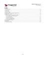
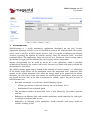
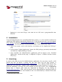
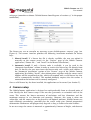
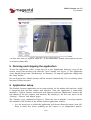
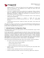
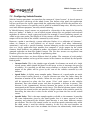
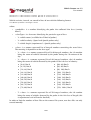
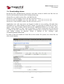
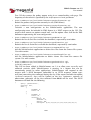
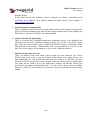
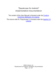
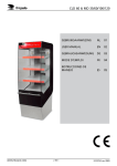
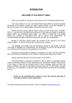
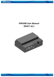
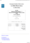
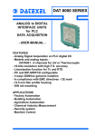
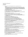
Vehicle Counter ver. 1.2 User manual Vehicle Counter ver. 1.2 User Manual 1/18 Vehicle Counter ver. 1.2 User manual Index 1 Introduction.......................................................................................................................................3 2 Installation.........................................................................................................................................4 3 Licensing...........................................................................................................................................4 4 Camera setup.....................................................................................................................................5 5 Running and stopping the application...............................................................................................6 6 Application setup...............................................................................................................................6 7 VehicleCounter Configuration Page..................................................................................................7 7.1 Configuring VehicleCounter......................................................................................................7 7.2 Preview pane............................................................................................................................10 7.3 Downloading data....................................................................................................................11 7.4 Downloading alarms................................................................................................................12 8 Programmable events......................................................................................................................13 9 Web API...........................................................................................................................................14 10 Troubleshooting.............................................................................................................................15 2/18 Vehicle Counter ver. 1.2 User manual Figure 1: The Axis camera Application Packages page 1 Introduction VehicleCounter is a traffic monitoring application developed on the Axis Camera Application Platform (ACAP). It can be installed on most of the ACAPenabled Axis camera server (such as the P33 or M32 camera servers), and it is capable of collecting meaningful statistics regarding the number of vehicles passing along the observed lanes, and their estimated speed. The application allows the user to set a number of virtual sensors and to decide how to aggregate the collected data by arraging sensors into probes. Sensors configuration can be made by means of a web application which is installed onboard and served by the camera web server. Statistics are stored and made available for download on a daily basis. The vehicle counter application is rooted on the concept of “virtual sensors”, i.e. subregions of the whole frame which can be positioned across the monitored lanes (crosswise with respect to the vehicle direction) that select the image pixels to be processed for vehicle detection. On each lane at least two sensors are usually placed (most often, three sensors are placed on each lane) to be able to estimate the vehicles speed. The main feature of VehicleCounter are: • Realtime estimation, in each lanes, of the following figures: ◦ vehicles per minute (estimated accuracy on a real dataset: 91%) ◦ distribution of the estimated speed • The maximum number of observable lanes is only limited by the camera position and lens • Robustness to different light and weather conditions: works correctly day and night, in sunlight, cloudy weather or rain • Robustness to different traffic conditions: works correctly with heavy traffic or vehicles standing in line 3/18 Vehicle Counter ver. 1.2 User manual Figure 2: The VehicleCounter License page • Optionally, it can store images and video on SD card with a programmable time schedule 2 Installation To install VehicleCounter on an ACAPenabled Axis camera, it is first needed to obtain the application EAP package provided by Magenta srl. If you do not have one, you can request it by writing an email to [email protected] or visiting http://www.magentalab.it/? page_id=189. The EAP package is freely downloadable. Then, follow these steps: 1. access the camera server web interface and browse to the “Application Packages” page 2. in the section “Upload Application” choose the EAP package previously downloaded and click the “Upload Package” button 3. once installed, the VehicleCounter application will be listed in the “Installed Application” section of the page, as depicted in Figure 1 (Vehicle Counter version may vary). 3 Licensing In order to be able to start the VehicleCounter application, the user must install a valid license key file. To obtain a license key, the user must visit the Axis website at http://www.axis.com/techsup/compatible_applications/. For a 90days trial license key, choose the “Get Trial Key” option, select “VehicleCounter from Magenta srl version x.y”1 from the combobox, and enter the serial number of your Axis camera. For a commercial license key, a license code must be requested to Magenta srl, by writing to [email protected]. Then, the full license can be downloaded by providing both the license code and the camera serial number in the “Get Activation key” section of the same 1 Choose the proper version number 4/18 Vehicle Counter ver. 1.2 User manual web page (remember to choose “VehicleCounter from Magenta srl version x.y” in the proper combo box). Figure 3: The VehicleCounter Settings page The license key can be installed by accessing to the VehicleCounter “License” page (see Figure 2). The camera interface provides the following installation methods for license keys: 1. Manual install. If a license key file is already available, the user can upload it manually to the camera server via the “License” page of the Vehicle Counter application (“Choose file...” and “Install” in the Manual Installation ). 2. Automatic install. If only a license code is available, it can be used in the “Automatic Installation” section in order to receive the license key file directly from Axis. To do this, the user must insert the license code and a valid email address in the “Automatic installation” section of the “License” page of the Vehicle Counter application. By clicking “Install”, these informations, together with the camera serial number will be transmitted to Axis, which will respond with a valid license key that will be automatically installed. This method obviously requires that the camera is connected to the internet and is correctly configured. Once a valid license key has been installed, the application can be started (see Section 5). 4 Camera setup The VehicleCounter application is designed to work preferably from an elevated point of view. Ideally, the best camera setup is the one that guarantees an azimuthal view of the scene. This ensures the lowest occurence of occlusions and lens distortions and the maximum accuracy in car detection and counting. However, this setup is often not achievable, and the camera has to be placed in suboptimal positions. VehicleCounter can work efficiently nevertheless, provided that the actual setup gives limited prospectical deformation. Performace will progressively degrade as long as camera elevation reduces. In our test setup, the camera is mounted at approximately 9 meters of height, and observes 5/18 Vehicle Counter ver. 1.2 User manual Figure 4: The VehicleCounter configuration page a 4lane road with an angle of about 45°. In this conditions, vehicle count proved to have an accuracy above 90%. 5 Running and stopping the application To run the application, select it from the list in the “Application Packages” page of the camera server web interface and click the “Start” button (see Figure 1). The application status should change from “Not Running” to “Running”. To stop the application simply click the “Stop” button. In case of power loss, Vehicle Counter will be restared automatically, if it was running when the power failure occurred. 6 Application setup The Vechicle Counter application can be setup entirely via the online web interface, which is integrated with the Axis camera web interface. Once the application is successfully installed, a “Vehicle Counter” menu voice will appeare under the “Application” menu in the left column of the Axis camera web interface. By selecting it, the user can access to the “Settings”, “License” and “About” pages. The “Settings” page (depicted in Figure 3) allows the user to provide a set of parameters that controls a few features of the vehicle counter application, namely: • fps: the frame rate at which the application grab frames from the sensor (max 30). Keep in mind that frame grabbing on the camera is an independent process. 6/18 Vehicle Counter ver. 1.2 User manual Grabbing frames at a frame rate higher than that the application can support will reduce the performance. We recommend not to change this unless you really underastand what you are doing. • resolution: resolution of the image grabbed by the application. Higher resolution means the application will process more pixels and this has an effect on the performance. The default is 320x240. We recommend not to change this unless you really underastand what you are doing. • loginterval: time in seconds between two consecutive writes in the system log (affects only the probes log). • httprequestrefresh: frequency in seconds at http://<camera-ip>/local/VehicleCounter/test2.cgi refreshed. • which the test page will be automatically framesbusybeforealarmraised: number of frames after which a busy sensor will raise an alarm. Also, from the “Settings” page the user can access to the VehicleCounter Configuration page by clicking on the “Main page” link. This will allow the user to configure the application by placing sensors and probes on the image frame. 7 VehicleCounter Configuration Page The VehicleCounter Configuration page provides several key functionalities. Figure 4 shows a screenshot of the page. On the right hand side, a customizable preview panel shows images taken from the camera sensor with the desired resolution and frame rate. Being a preview panel, both resolution and frame rate can be reduced to ease configuration procedure while using lowbandwidth connections. Currently configured virtual sensor are drawn as blue rectangles superimposed on the camera image. Note that the preview panel keeps its original size of 640x480 pixels even if the user choose a lower resolution (the image quality is reduced). This should ease the configuration of new virtual sensors, as described below. The left hand side of the configuration page shows several elements. From top to bottom: • the treelike structure of the current configuration, with controls for: ◦ adding Counter, Speed and Speed2 probes ◦ save the configuration to camera ◦ load the configuration currently in use from camera • controls to move and resize virtual sensors on the preview pane (only visible when editing a sensor) • controls to change resolutions and frame rate of the preview panel • controls to download and delete statistics and alarms log, updated on a daily basis 7/18 Vehicle Counter ver. 1.2 User manual 7.1 Configuring VehicleCounter Vehicle Counter operations are rooted on the concept of “virtual sensor”. A virtual sensor is just a rectangular subimage of the whole frame, that defines what pixels the application will use to extract the signals upon which the application logic will infer the presence of a vehicle. Virtual sensors are typically used in place of traditional loop wires, but they can be used with different purposes, not only vehicle counting. In VehicleCounter, virtual sensors are organized in a hierarchy. At the top of the hierarchy there are “probes”. A Probe is a set of virtual sensors whose data are grouped and analyzed toghether to achieve a single aggregated result. For example, if several counting sensors are added to the same probe, the output of all the sensors will be summed up, and the probe's output will be the sum of the vehicle's counted by each sensor. However, a probe is not directly a sensor collection. Rather, it is a collection of “elements”, where an element is a well defined set of virtual sensors (and other information, sometimes), each with a specific function. Sensors belonging to the same element provide data to a single application logic module that computes a single output for the whole element. Since elements are grouped in probes, the outputs of each element of a probe are grouped toghether to form that probe's output. The fact that sensors are organized into elements gives the user more flexibility in positioning them. In VehicleCounter there are three different kind of probes. The structure of each probe's element and the number and usage of the sensors in the element are defined by the specific kind of probe. • Counter Probe. This is the simplest type of probe. Its elements are made of a single virtual sensor, which should be placed in the image so that it intercepts the passage of vehicles. It is possibile to add how many elements as desired to the probe. The output of the probe will be given by the sum of the vehicles counted by each element. • Speed Probe. A slightly more complex probe. Elements of a speed probe are made of two virtual sensor, placed at a certain distance one ofter the other along the direction of motion of the vehicles. When the user place a speed probe sensor, he will be requested to place the first sensor (“first” with respect to che vehicles direction), then the second sensor, and then to provide a distance in meters. This distance is the (approximate) distance between the points in the real world that correspond to the sensors position on the image. This kind of element counts vehicle passing on the second sensor and provides a rough estimate of the vehicles speed, by measuring the time that it takes to the vehicle to get from the first to the second sensor. • Speed2 Probe. This is the most complex probe available at the moment. It provides the same information given by the Speed probe, but it is more accurate in both counting and estimating the vehicles speed because it uses three different sensors per element. The first and second sensor are used for speed estimation only, while the third sensor is used for vehicles counting. In this way, the two functions are decoupled, and the user is free to choose the sensors size conveniently: thick sensors 8/18 Vehicle Counter ver. 1.2 User manual for speed estimation, thin sensor for vehicles counting. In Figure 4, the preview pane shows a configuration made up of 12 sensors (the blue boxes drawn upon the image), organized in 2 probes (both are Speed2 probes), one for each direction of the vehicles. Each probe is made up of 2 elements, since this is a convenient setup for this particular usecase: one element for each road lane. And since the probes are Speed2 probes, their elements are made of 3 sensors each: two of them are used to estimate vehicles speed (they are named “in” and “out” sensor respectively), while the third sensor (named “counter” sensor) is use for counting only. Usually, the counter sensor is thinner with respect to the “in” and “out” sensor, to reduce the possibility that two vehicles could occupy the same sensor at the same time. While this is not a problem for speed estimation, it is undesirable in vehicle counting, because it makes two vehicles appear as one. To detect the presence of the vehicle, each sensor extract a onedimensional signal from the pixel values it includes. The sensor is considered “busy” (vehicle on sensor) when this signal's value is above a certain threshold named “top threshold” in Vehicle Counter. To prevent the sensor from oscillating between “busy” and “nonbusy” states, and to reduce false positives, the onedimensional signal's value has to drop below a different threshold, lower than the top threshold. This one is called “bottom threshold”. Both values can be changed in the treelike view in the configuration page. Top and bottom threshold values are assigned to the probe and inherited by elements and sensors in that probe. Once all the desired probes have been defined and placed, the configuration can be saved to camera by clicking the “Save to camera” link at the bottom of the treelike view. Since the VehicleCounter application is supposed to work outdoor and is likely to be not immediately at hand for maintenance, it is important to ensure that the application is always capable to restart autonomously with a valid configuration. For this reason, configuration changes are done in two steps. At first the new configuration is encoded in XML and sent to camera, which verifies its correctness. Then, if the new configuration is valid, it is stored in the file system so that it becomes fully functional at the next application restart. If, for any reason, this process fails before the last step, the application is capable to recover the previously used probes configuration, and the attempted configuration change is discarded. 9/18 Vehicle Counter ver. 1.2 User manual Figure 5: The Editor pane, with text boxes for manual set of position and size folded (left) and unfolded (right). When the VehicleCounter Configuration Page is loaded in the browser, a request for the current probes configuration is immediately sent to the camera server in order to draw the probes on the preview pane. However, the user can explicitly request to reload the current configuration from the running application by clicking the “Load from camera” link at the end of the treelike view. It has to be noted that the application responds to this request with the probes configuration that is currently in use, retrieving it from memory, regardless of the configuration stored in the file system. For this reason, even when a new configuration has been saved to camera, it is still possible to recover the previous configuration just by clicking “Load from camera”, followed by “Save from camera”. The previous probes configuration only became unrecoverable after saving the new one with “Save from camera”. Configured probes can always be corrected in position and size by clicking on the “edit” icon of a sensor in the treelike view. The corresponding sensor in the preview pane will be redrawn with a dashed line, and the “Editor” section appears below the treelike view. The editor shows: • A text string explaining exactly which sensor the user is editing • Controls (text boxes) for entering exact position and size of the sensor • Buttons to enable the “move” and “resize” mode. To move a sensor from its current position, click the sensor's “edit” icon in the treelike view, click the “move” button in the “Editor” section and drag the mouse in the preview pane. To resize a sensor, follow the same instructions but click the “resize” button instead of the “move” button. To enter exact position and/or size for a particular sensor, unfold the text boxes under the “Manually set...” button in the Editor section, enter the desired values and click the “Manually set...” button. 7.2 Preview pane The preview pane shows live images from the camera sensor with the current configuration drawn on top of it. Since it is likely that the Vehicle Counter application will be configured with the camera already on site, it is important for the configuration page to be usable even 10/18 Vehicle Counter ver. 1.2 User manual with lowbandwidth connections. For this reason, the video stream played in the preview pane is a (possibly) low bitrate mjpeg stream. The “Preview setup” section allows the user to choose the resolution of jpeg in the preview pane (704x576, 640x480, 352x288, 320x240, 176x144, 160x120) and the frame rate of the mjpeg stream. However, the main purpose of the preview pane is to allow the user to draw the sensors on a reference image. For this reason, regardless of the chosen image resolution, the preview pane will keep its original size of 640x480 pixels, eventually degrading image quality, to ease the process of drawing the sensors. Please note that the resolution at which the VehicleCounter application works may be different and can be changed in the application “Settings” page (see section 6). Below the area where jpeg images are displayed, two buttons are placed that can be used to show or hide the “live capture” of data from the camera. By clicking “Show Probes Output”, the browser will start to receive a textual stream with live information from the configured probes, which will be displayed on screen. The information received will look like shown below (this example refers to the case of 2 probes): 1132: Probe 0: 0 [0][0 km/h] | Probe 1: 0 [0][0 km/h] | 0 The first number is a frame counter. In normal conditions of operation, this number should be increasing. Then, for each probe, a string of text is reported with the following format: Probe <ProbeIdx>: <Count> [<CountSinceLastLog>][<LastEstimatedSpeed>] | • ProbeIdx is obviously the probe index • Count is total number of vehicles counted by these probe • CountSinceLastLog • LastEstimatedSpeed is the last estimated (approximate) speed (Speed and Speed2 is a partial counter that is reset to zero every time that VehicleCounter writes a line a the system log (configurable – default 60 seconds) probes only) Finally, at the end of the line, the total count of vehicles detected by all configured probes is reported. The character '|' (pipe) is used as a separator between strings from different probes. 7.3 Downloading data The purpose of VehicleCounter is to collect statistics about the observed traffic flows. These data are stored in text files on the camera file system that are listed in the “Download” section of the VehicleCounter Configuration page (Figure 4). From there, data files can be downloaded and deleted. Data files are text files updated on a daily basis. Each line of text has the format: YYYY-MM-DD:<data> Beside real data, these files also report application start and stop with the followings lines of text: 11/18 Vehicle Counter ver. 1.2 User manual 2013-02-26:*** VehicleCounter stopped: Tue Feb 26 11:42:27 2013 *** 2013-02-27:*** VehicleCounter started: Wed Feb 27 15:53:45 2013 *** Vehicle statistics, instead, are stored in lines of text with the following format: YYYY-MM-DD:<probeIdx>:<dataType>:<data> where: • <probeIdx> is a number identifying the probe that collected that data (starting from 1) • <dataType> is a character identifying the particular type of data: ◦ 'c': vehicle count (available for all kind of probes) ◦ 'v': vehicle velocity (Speed and Speed2 probes only) ◦ 'l': vehicle length (experimental – Speed2 probes only) • <data> is a comma separated list of integral numbers containing the actual data. The meaning is dependant on the data type: ◦ 'c': <data> is a comma separated list of 1440 integral numbers, the ith number being the count of vehicles detected by the probe during the ith minute of the day. ◦ 'v': <data> is a comma separated list of 20 integral numbers, the ith number being the count of vehicle detected by the probe in the ith class of velocity: ▪ [0; 8) Km/h ▪ [80; 88) Km/h ▪ [8; 16) Km/h ▪ [88; 96) Km/h ▪ [16; 24) Km/h ▪ [96; 104) Km/h ▪ [24; 32) Km/h ▪ [104; 112) Km/h ▪ [32; 40) Km/h ▪ [112; 120) Km/h ▪ [40; 48) Km/h ▪ [120; 128) Km/h ▪ [48; 56) Km/h ▪ [128; 136) Km/h ▪ [56; 64) Km/h ▪ [136; 144) Km/h ▪ [64; 72) Km/h ▪ [144; 152) Km/h ▪ [72; 80) Km/h ▪ [152; 160+) Km/h ◦ 'l': <data> is a comma separated list of 50 integral numbers, the ith number being the count of vehicles detected by the probe in the ith class of length (this is experimental and will not be detailed). In order to limit the number of data files on the camera file system, new data files are only created monthly. 12/18 Vehicle Counter ver. 1.2 User manual 7.4 Downloading alarms Beside data files, VehicleCounter generates and stores alarms in similar text files that are listed in the Download section of the Configuration page. Alarms files are similar to data files, and look like this: 2013-02-26:*** VehicleCounter started: Tue 2013-02-26:[sensor #1] WARNING: busy since 2013-02-26:[sensor #3] WARNING: busy since 2013-02-26:*** VehicleCounter stopped: Tue Feb 26 11:38:56 1000 frames ago 1000 frames ago Feb 26 11:42:27 2013 - at - at 2013 *** Tue Feb 26 11:42:01 2013 Tue Feb 26 11:42:01 2013 *** Application start and stop event are logged in order to ease reading. All other lines correspond to an equal number of alarms. Alarms are generated to notify the fact that a sensor is not able to count vehicles because the application believe it is in “busy” state. When a sensor remain in “busy” state for too long, an alarm is generated and a line of text is added in the daily alarm log. The number of frames that a sensor can remain in busy state before starting to generate alarms is defined in the “Settings” page (framesbusybeforealarmraised). In order to limit the number of alarm files on the camera file system, new alarm files are only created montly. Figure 6: The Triggered Event Type Setup page 13/18 Vehicle Counter ver. 1.2 User manual 8 Programmable events The VehicleCounter application generates two types of event that integrates perfectly the event management system of the Axis camera servers: • stop event: generated when VehicleCounter is stopped by a SIGINT. • alarm event: generated when a virtual sensor raises an alarm These events allow the user to schedule actions (i.e. sending an email, recording a video, storing a picture) when one of them occurs. Alarm events are particularly interesting. By scheduling the recording of a few frames of video in response to an event, it will be possible to understand what made the sensor raise an alarm and if the sensor was actually detecting a vehicle or a false positive occurred. To react to the raise of an event (either a stop event or an alarm event), the user must add a new triggered eventi in the camera server event system. In the section “Events”, “Event Types”, clicking the button “Add triggered...” will show the page in Figure 6. There, the user can decide: 1. which name to give to the triggered event; 2. the priority level (with respect to the other events); 3. the minimum time interval to wait after a trigger before the same event is allowed to be triggered again 4. a weekly schedule of time periods during which the trigger is enabled 5. which is the trigger 6. what to do when the event is triggered Point 5 is what makes the difference between VehicleCounter events and other events. When VehicleCounter is running, in the first combo box in the “Triggered by...” section it is possible to choose “Application trigger”. This will populate the second combo box with events defined by the currently running application. For VehicleCounter, possible choices are “VehicleCounter: stop” and “VehicleCounter: alarm”. After that, in point 6 the user can choose what to do when the event is triggered. After checking out the desired options, the page will show up additional controls based on the particular choice. 9 Web API The VehicleCounter application defines several CGI that are used by the web interface to interact with the running application. These CGI are public and can be used by other system to communicate with the web application. What follows is a list of available CGIs. • http://<address-ip>/local/VehicleCounter/test.cgi • http://<address-ip>/local/VehicleCounter/test2.cgi Test CGI that returns the probes output string 14/18 Vehicle Counter ver. 1.2 User manual Test CGI that returns the probes output string in an autorefreshing web page. The frequency of the refresh is specified by the httprequestrefresh parameter • http://<address-ip>/local/VehicleCounter/getConfiguration.cgi • http://<address-ip>/local/VehicleCounter/setConfiguration.cgi Return the probes configuration currently in use (XML format) Transmit a new configuration to the VehicleCounter application. The new configuration must be included in XML format in a POST request to the CGI. The request shall contain an option named 'xml', and the option value shall be the XML document representing the new configuration. • http://<address-ip>/local/VehicleCounter/getDataList.cgi • http://<address-ip>/local/VehicleCounter/getAlarmsList.cgi Returns the list of data files available for download, separated by semicolon. Returns the list of alarm files available for download, separated by semicolon. • http://<address-ip>/local/VehicleCounter/eraseDataFiles.cgi • http://<address-ip>/local/VehicleCounter/eraseAlarmsFiles.cgi Ask the VehicleCounter application to delete data files from the camera file system. Use with caution. Ask the VehicleCounter application to delete alarms files from the camera file system. Use with caution. • http://<address-ip>/local/VehicleCounter/getStatistics.cgi http://<address-ip>/local/VehicleCounter/getStatistics.cgi? interval=<minutes> This CGI has been added in VehicleCounter ver. 1.2 to allow users to easily read collected statistics while VehicleCounter is running, in a format that can be conveniently parsed by other applications. VehicleCounter will respond to this request with a JSON document embedded in an HTTP response (mime type: text/json) containing data collected during the day. If the request includes the option ?interval=<minutes>, data will be limited to the last <minutes> minutes of observation, otherwise all the data collected from 00.00 will be used. The JSON document will look like the following: { "query": "getStatistics", "interval": null, "data": [ { "probeId": 0, "count": 20 }, { "probeId": 1, "count": 34, "velocity": { "nbins": 20, "binwidth": 8, "maxval": 160, "histogram": [0,9,4,2,0,0,0,0,1,0,2,0,12,0,0,0,0,0,0,1] } }, { 15/18 Vehicle Counter ver. 1.2 User manual } ] } "probeId": 2, "count": 16, "velocity": { "nbins": 20, "binwidth": 8, "maxval": 160, "histogram": [0,1,2,1,3,0,0,0,0,1,0,0,1,0,4,0,0,0,0,0] } The JSON document contains three elements: “query”, “interval” and “data”. The value of “query” key is always “getStatistics”. The value of “interval” key reports the value of the “interval” options received by VehicleCounter. If no interval option was present in the request, the value null is reported. The value of “data” key is an array of object, one per probe. Each object contains the statistics of a probe. All probes reports the following data: ◦ “probeId”: numeric id of the probe ◦ “count”: vehicles counted by the probe in the requested time interval If the probe is a Speed or a Speed2 probe, it will also report velocity data in the form of an histogram contained in the JSON object “velocity”. The following keys will be included: ◦ “nbins”: number of bins in the velocity histogram ◦ “binwidth”: width (in km/h) of each histogram's bin ◦ “maxval”: maximum velocity reported in the histogram ◦ “histogram”: a vector of “nbins” values representing the velocity histogram The histogram format is the same explained in Section 7.3. If the request contains an “interval” option, for each probe a “duration” key will be reported with value equal to the actual duration of the time interval used to aggregate statistics. 10 Troubleshooting 1. The sensors start counting a few seconds after the application has started, and they do not start counting at the same time. Why? When the application starts, configured sensors have to learn the background value of the signal extrated by the pixels, so to be able to detect the variations due to the vehicles passing onto the sensors. This process requires some time, which is dependent on the local conditions of scene at each sensor. During this time, the sensor is not available for counting. So, some sensor could start counting immediately, while some other sensor could start counting after a while 2. Some sensors do not seem to count at all. There could be two reasons for this behaviour. 16/18 Vehicle Counter ver. 1.2 User manual a. Check the size of your counting sensor. Sometimes, a small counting sensor could be reduced a zerowitdth or a zeroheight sensor when the 640x480 drawing on the preview pane is reduced to the size of the images actually used by the VehicleCounter (which is likely 320x240 or smaller). Try with a bigger counting sensor. b. The sensor cannot learn the background signal. Sometimes, it can happen that the sensor never reach its operational phase because it cannot learn the background signal. In this case, it can help rising the top threshold, since the sensor starts counting when the signal extrated from the pixels (minus the background signal) falls below the top threshold. If this does not work, try a different position for the counting sensor. 3. I get a lot of “busy” alarms from a particular sensor. What can I do? First of all, it can be of great help to capture images of the event that caused the alarm to occur. For this, use the programmable alarm event as described in Section 8. Then, it is likely that the pixels observed by that sensor suffer from sudden variations, such that the application believes they are due to a vehicle passing onto the sensor. Examples of situations that can occasionally cause this behaviours are: objects moving in front of the camera, partial or total occlusions of the camera, unusually sharpedged casted shadows. In this cases, the user can either: a. raise the bottom threshold: this will make it easier for the sensor to transit from the “busy” state (above the top threshold) to the “nonbusy” state (below the bottom threshold). b. enlarge the sensor: bigger sensors tend to collect smoother and lower signals with respect to small sensors. This should make it easier for the sensor to transit from the “busy” state to the “nonbusy” state. 4. I cannot install the EAP package and/or the license key. There is a known bug in several Axis firmwares affecting several different camera models. The bug regards a missing library link, that prevents the application from finding a shared library at loading time. This bug prevents the package from being accepted by the camera verification system, and can only be fixed by Axis (which is already informed) by distributing a new version of the camera firmware to be installed onto the camera. In the meantime, Magenta srl has developed a patch that provides a workaround. The patch is distributed as a standalone ACAP application. The user can download the patch EAP package visiting Magenta's website at http://www.magentalab.it/? page_id=189. This package must be installed as any other ACAP application, and it will be listed in the “Application packages” page of the Axis camera server as “Magenta patch”. However, it does not need to be executed (the application itself does not do anything and will terminate immediately if started). As long as the patch is installed, it provides the missing links to other ACAP application, like 17/18 Vehicle Counter ver. 1.2 User manual VehicleCounter. If this does not fix the problem, contact Magenta srl. Write a detailed email describing your problem, your camera model and your camera serial number, at [email protected]. 5. Internet Explorer compatibility. There are known issues with the javascript code in the Vehicle Counter configuration page and Internet Explorer that prevents our configuration tool to work properly on this browser. Chrome and Firefox are recommended. 6. Google Chrome file upload bug. There is a known bug in Google Chrome that sometimes causes a file upload to fail with the error message “Could not upload package file, the file is too large or disk full”. This may occur while trying to upload the Vehicle Counter or Magenta Patch EAP package to the camera. Unfortunately, this is not something we can fix, so the only fix we can suggest at the moment is to try with a different browser. 7. Vehicle Counter does not run. There are known issues with some recent versions of Axis firmware that causes Vehicle Counter to crash at start up. If none of the above issues apply, please save both application log and system log from your Axis camera to text files and send them to us. Please specify your camera model, firmware version and what operations you made on the camera or on the application (package installation, license key installation, parameter configurations etc.). Or, you can try with a newer (or older) firmware. Check the Axis website for firmware versions available for your camera model. 18/18