1
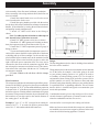
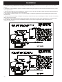
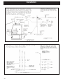
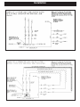
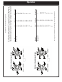
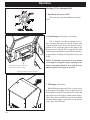
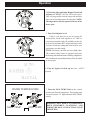
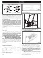
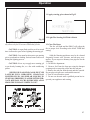
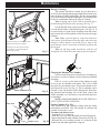
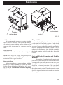
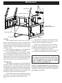
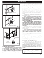
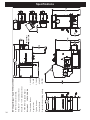
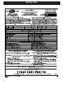
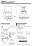
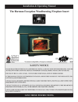
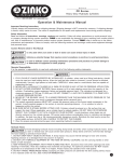
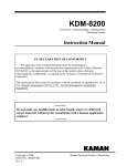
Installation & Operating Manual
The Harman PB 105 Pellet Boiler
Portland
“Ce manuel est disponible en Français sur demande”
R3
SAFETY NOTICE
Please read this entire manual before you install and use your new Boiler. Failure to
follow instructions may result in property damage, bodily injury, or even death.
FOR USE IN THE U.S. AND CANADA. SUITABLE FOR INSTALLATION IN MOBILE HOMES
IF THIS HARMAN Pellet BOILER IS NOT PROPERLY INSTALLED, A HOUSE FIRE MAY RESULT. FOR YOUR
SAFETY, FOLLOW INSTALLATION DIRECTIONS.
CONTACT LOCAL BUILDING OR FIRE OFFICIALS ABOUT RESTRICTIONS AND INSTALLATION INSPECTION
REQUIREMENTS IN YOUR AREA.
Contact your local authority (such as municipal building department, fire department, fire
prevention bureau, etc.) to determine the need for a permit.
Cette guide d’utilisation est disponible en francais. Chez votre concessionnaire de Harman Stove Company.
save these instructions
Manual #3-90-07205
1-1/4” FMPT Supply
Access Cover To Secondary Ash Chamber
Ash Door
Firebox Door
Viewing Glass
Hopper / Swing Plate Knob
Access Cover To
Control Board Cover
Control Board
Hopper
Hopper Lid
Latches
PB105 Parts
1/2” FMPT Boiler Drain
Combustion Blower Cover
Combustion Blower
Vent Pipe
1-1/4” FMPT Return
(Removed w/ Domestic
Hot Water Option)
Blank Cover
Pressure Relief Valve
Aquastat Well
Temperature / Pressure Gauge
PB105 Parts
Table of Contents
Assembly
5
Venting
9
Installation 12
Operation
21
Maintenance 28
Troubleshooting
32
Feeder Parts
33
Specifications
34
Wiring Diagram
35
Parts List & Options
36
Warranty 37
Testing Label
38
Quick Reference Start-Up Back Cover
Please read this entire manual before you install and use your new
boiler. Failure to follow instructions may result in
property damage, bodily injury, or even death.
SAVE THESE INSTRUCTIONS
Harman Home Heating
352 Mountain House Road
Halifax, PA 17032
Outdoor Air Temperature Sensor Wiring :
Assembly
Assembly
Boiler Kit Materials: (Refer to pages 4 & 5)
List of items contained within the boiler kit shipped with
the unit.
1 - Control board cover
1 - Access cover (Hopper Swing Plate Knob)
5 - Spring Handles
1 - 1/2” Boiler Drain
1 - 3/4” Safety Relief Valve
1 - 1/2” Aquastat Well
1 - 1/2” Dual Temperature/Pressure Gauge
1 - 100ft. Sensor Cable (Outdoor Air Sensor)
1 - Outdoor Air Sensor
1 - Flue Tunnel Weldment
1 - Combustion Blower Assembly
1 - Heat Shield (Comb. Blower)
2 - UY Connectors
2 - Terminals 1/4 Female
1 - #8 X 1/2” TEK
3 - 1/4-20 X 5/8” Wing Screw
4 - 1/4” Lock Washer
4 - 1/4-20 Nuts
Installation of the Flue Tunnel Weldment,
Combustion Blower and Wiring, ESP and Heat
Shield:
Step 1: First install the flue tunnel weldment by
aligning the (4) studs up with the (4) holes in the ash
chamber base. Fasten the (4) nuts and lock washers
provided, to the studs by removing the access cover on
the secondary ash chamber.
Step 2: Place the combustion motor onto the flue tunnel
weldment and tighten the (3) wing screws provided.
Step 3: Insert the Exhaust Sensing Probe (ESP) into the
1/8” hole provided on the flue pipe stub. Fasten with
the (1) #8x1/2” TEK screw also provided. ESP will be
taped to the sheet metal jacket for shipping purposes.
Step 4: Connect the flex conduit 90 degree elbow(Not
Shown) to the heat shield in the hole provided. Then
connect the (3) wires from the combustion blower with
the (3) wires in the flex conduit by using the push-on
connectors and matching the wire colors as follows:
Red to Black, White to White and Green to Green.
Step 5: Place Heat Shield over combustion blower and
align the swell latches with the holes in the sheet metal
and tighten.
Flue Tunnel Weldment
ESP Probe
Combustion Blower
Heat Shield
NOTE: Refer to Fig’s 22, 23 and 24 located in the
maintenance section of this manual.
Assembly
After assembly of the flue tunnel weldment, combustion
blower assembly with wiring and heat shield, the boiler can
now be installed.
1. Install the control board cover as well as the access
cover located on the feeder cover.
2. Install the spring handles provided with the unit on
the ash door, firebox door and the heat exchanger cleanout rod
handles. (Fasten handles by turning them counterclockwise
and pushing inward simultaneously).
3. Install 1/2” MPT boiler drain in the fitting as
shown.
Note: Use teflon pipe thread sealant or teflon tape on
ALL threads before connections are made.
4. Install 3/4” MPT pressure relief valve as shown.
5. Install the 1/2” MPT aquastat well in fitting as shown,
then place aquastat in the well and fasten with a zip tie.
6. Install the 1/2” MPT temperature/pressure gauge in
fitting as shown.
7. Locate and install outside air temperature sensor. Location of this sensor should be on the north side of the home
or building and out of direct sunlight. Use the cat cable supplied with the boiler to attach sensor to the terminals located
on the hopper. (Place at the back side just above and to the
right of the main power connection box) The wires can be
connected to the sensor with the connectors supplied. Wire
nut or butt splice connectors could also be used. The connections at the boiler can be done with the two 1/4” female push
on connectors supplied.
8. Fasten conduit to the ash base with the clamps
provided.
MINIMUM NON-COMBUSTIBLE FLOOR PROTECTION
AREA
Design:
The first thing that needs to be done is deciding where and how
the boiler will be installed.
Things that need to be taken into consideration are the intended
use of the boiler for example, is the boiler going to be used
as your primary heating system or is it going to be used as
a secondary or backup heating system. If it is to be used in
conjunction with an existing oil or gas boiler system will it be
piped in parallel or in series? The answers to these and other
questions can be determined by talking to your certified dealer
or a qualified HVAC or plumbing contractor. This will insure
that the boiler is installed and piped to accommodate your
needs and expectations.
Floor Protection:
The striped area indicates the minimum required floor protection area if the PB105 is going to be placed on a combustible
floor. It requires 30” X 55” of non combustible floor protection
as shown below. 6” of the floor protection must be in front of
the boiler as shown. Flooring must be a minimum of 26 gauge
sheet metal. Floor protection must also be provided under any Consideration must be given to the venting as well as electrihorizontal run of vent pipe equal to the outside diameter of cal and clearance requirements. (Clearances must be mainthe venting plus 2” to each side.
tained to combustibles and also for service)
Example: 4” type “L” or “PL” vent pipe has an outside di- After the boiler is set into place the venting can be done.
ameter of 4-1/2” + 2” on each side equals a protected floor
area of 8-1/2” wide underneath the horizontal run.
Make sure fans are not used in the fuel storage area, unless they
are installed so as not to create a negative pressures in the room
where the solid fuel burning appliance is located.
Assembly
When installing the PB105 in a mobile home several
requirements must be followed:
1. The unit must be bolted to the floor.
2. The unit must be connected to outside air.
3. Floor protection and clearances must be followed.
4. Unit must be grounded to the metal frame of the
mobile home.
INSTALLATION IS TO BE PERFORMED BY A
QUALIFIED INSTALLER.
NOTE: All installation clearances and restrictions
must be adhered to.
NOTE:Use only 4” diameter type “L” or “PL” venting
system. Be sure to inspect and clean exhaust venting
system frequently.
Venting
Requirements for Terminating the Venting
WARNING: Venting terminals must not be recessed into a wall or siding.
NOTE: Only PL vent pipe wall pass-throughs and
fire stops should be used when venting through combustible materials.
NOTE: Always take into consideration the effect
the prevailing wind direction or other wind currents
will cause with flyash and /or smoke when placing the
termination.
In addition, the following must be observed:
A. The clearance above grade must be a minimum
of 18”.1
B. The clearance to a window or door that may
be opened must be a minimum of 48” to the side, 48”
below the window/door, and 12” above the window/
door.1
( with outside air installed, 18” )
C. A 12” clearance to a permanently closed window is recommended to prevent condensation on the
window.
D. The vertical clearance to a ventilated soffit
located above the terminal within a horizontal distance
of 2 feet (60 cm) from the center-line of the terminal
must be a minimum of 18”.
E. The clearance to an unventilated soffit must be
a minimum of 12”.
F. The clearance to an outside corner is 11” from
center of pipe.
G. The clearance to an inside corner is 12”.
= Vent terminal
= Air supply inlet
H. A vent must not be installed within 3 feet (90
cm) above a gas meter/regulator assembly when measured from the horizontal center-line of the regulator.1
I. The clearance to service regulator vent outlet
must be a minimum of 6 feet.1
J. The clearance to a non-mechanical air supply
inlet to the building or the combustion air inlet to any
other appliance must be a minimum of 48”.1
K. The clearance to a mechanical air supply inlet
must be a minimum of 10 feet.1
(with outside air installed, 6 feet )
L. The clearance above a paved sidewalk or a
paved driveway located on public property must be a
minimum of 7 feet.1,2
M. The clearance under a veranda, porch, deck or
balcony must be a minimum of 12 inches.1,3
NOTE: The clearance to vegetation and other
exterior combustibles such as mulch is 36” as measured
from the center of the outlet or cap. This 36” radius
continues to grade or a minimum of 7 feet below the
outlet.
1
Certain Canadian and or Local codes or regulations may require different clearances.
2
A vent shall not terminate directly above a sidewalk or paved driveway which is located between two
single family dwellings and serves both dwellings.
3
Only permitted if veranda, porch, deck, or balcony is fully open on a minimum of 2 sides beneath
the floor.
NOTE: Where passage through a wall, or
partition of combustible construction is desired,
the installation shall conform to CAN/CSA-B365.
(if in Canada)
= Area where terminal is not permitted
Fig. 2
Fig. 3
Venting
10
Venting
Venting
Venting
Use 4” pellet vent pipe to vent your PB105.
A combustion blower is used to extract the combustion
gases from the firebox. This creates a negative pressure in
the firebox and a positive pressure in the venting system
as shown in Fig. 4. The longer the vent pipe and more
elbows used in the system, the greater the flow resistance.
Because of these facts we recommend using as few elbows
as possible and 30 feet or less of vent pipe. The maximum
horizontal run should not exceed 18 feet.
Be sure to use wall and ceiling pass through fittings
(which are approved for pellet vent pipe ) when going
through combustible materials. Be sure to use a starting collar to attach the venting system to the stove. The
starting collar must be sealed to the stove flue collar
with high temp silicone caulking or aluminum tape,
and screwed into the stove flue collar at least three (3)
places.
+
-
Fig. 4
Vent Pipe
4” pellet vent pipe (also known as “L or PL” vent) is
constructed of two layers with air space between the layers.
This air space acts as an insulator and reduces the outside
surface temperature to allow a minimum clearance to combustibles of 1 inch. In Canada the minimum clearance to
combustibles is 3 inches.
The sections of pipe lock together to form an air tight
seal in most cases; however, in some cases a perfect seal
is not achieved. For this reason and the fact that the PB105
operates with a positive vent pressure, we specify that all
joints within the structure should also be sealed with
clear silicone.
NOTE:Use only 4” diameter type “L” or “PL” venting
system. Be sure to inspect and clean exhaust venting
system frequently.
4” Type “L” or
“PL” Vent pipe
Fig. 5
This is the minimum venting configuration.
The minimum vent configuration is a 90o or Tee on
a starter collar and a 24” length horizontal through an
exterior wall. A cap on the end should direct the flue
gasses down and away from the structure. See Fig. 5.
The maximum horizontal length is 18 feet. The
minimum termination height above the exterior grade
is 18”. The maximum total length of any configuration
is 30 feet*.
* ( see venting graph on page 10 for exceptions )
NOTE: Cleanout Tee’s should always be used on the
transitions to horizontal pipe to allow easy access for
cleaning.
The venting graph allows for one(1) 90 deg. or Tee
fitting in any configuration.
If more 90’s, T’s, or 45’s are needed the total length
must be adjusted to allow for the added restriction.
Up to four (4) additional 90’s, Tee’s, or equivalent 45’s
can be added as long as the overall length is adjusted in
accordance with the values listed below.
( See the venting graph on page 10.)
Each Vertical ---- 90 deg. or T subtract 2.5 feet
Each Vertical ---- 45 deg.
subtract 1.5 feet
Each Horizontal - 90 deg. or T subtract 5.0 feet
Each Horizontal - 45 deg.
subtract 2.5 feet
Any exterior venting (vent pipe exposed to outside
ambiant temperatures) should be kept to a minimum,
due to potential condensation problems.
This is especially important in high humidity cold
weather climates, such as maritime areas, lake shores,
and low river valleys.
11
Venting Installation
NOTE: Use only 4” diameter type “L” or “PL”
venting system. Be sure to inspect and clean
exhaust venting system frequently.
INSTALLATION IS TO BE PERFORMED BY
A QUALIFIED INSTALLER.
DO NOT INSTALL A FLUE DAMPER IN THE
EXHAUST VENTING SYSTEM OF THIS
UNIT.
DO NOT CONNECT THIS UNIT TO A
CHIMNEY FLUE SERVING ANOTHER
APPLIANCE.
Chimneys taller than 20’ above the connection will
require a draft test to determine if the draft is too high.
Note: The High Burn Draft should not exceed .85
IWC. Some form of a restrictor plate may be required at
the top of high chimneys to reduce the draft. See page
20 for the Draft Test procedure.
The PB105 Boiler may be used and installed into
an existing masonary or Class A metal chimney.
Certain Canadian and Local Codes may require that
the chimney be fully relined.
The venting Can Not be installed in a chimney
serving another appliance.
The chimney should be cleaned and or inspected
before installation of the venting.
INSTALL VENT WALL PASS-THROUGHS AT
CLEARANCES SPECIFIED BY THE VENT
MANUFACTURER
NOTE: All installation clearances and restrictions
must be adhered to.
NOTE: Read and follow all of the vent pipe
manufacturers’ instructions on the proper
installation and support of the vent pipe. Adhere
to all clearances.
WARNING
Keep combustible materials such
as grass, leaves, etc. at least 3 feet
away from the point directly under
the vent termination. (between the
vent and the ground)
WARNING
MOBILE HOME GUIDELINES DO NOT
ALLOW INSTALLATION IN ANY ROOM
DESIGNATED FOR SLEEPING.
CAUTION
Other examples of possible installations of the venting.
Keep combustibles away
from flue outlet.
Creosote - Formation and Need for Removal - When wood is burned slowly, it produces tar and other organic vapors,
which combine with expelled moisture to form creosote. The creosote vapors condense in the relatively cool chimney flue
of a slow-burning fire. As a result, creosote residue accumulates on the flue lining. When ignited, this creosote makes an
extremely hot fire. The pellet vent pipe should be inspected at least twice monthly during the heating season to determine if
a creosote buildup has occurred. If creosote has accumulated it should be removed to reduce the risk of a chimney fire.
Guidance on minimizing creosote formation and the need for periodic creosote removal: The chimney should be
inspected during the heating season to determine if a creosote build-up has occurred. If a significant layer of creosote has
accumulated (3mm or more) it should be removed to reduce the risk of a chimney fire.
12
Installation
Outside Air
Inlet Cover part#
1-10-09542
Fig. 6
Outside Air Pipe
Knockout
Feeder Cover
Fig. 7
Outside Air Inlet Pipe
Outside air is optional, although it may be
required by some building codes. The benefit of
outside air is higher efficiency and reduced venting
restrictions.
To install outside air, use 2 3/4” I.D.galvanized
steel flex pipe, part # 2-00-08544 ( 12’ 6” length) or
part # 2-00-08545 ( 25’ length) See Fig. 6. There is
a break-away hole on the rear panel which must be
removed before connecting the flex pipe. See Fig.
7. The pipe should be run outside and terminate 3
feet or more below or 1 foot or more to the side of
the vent pipe outlet. Never terminate the outside air
above the vent pipe outlet. The maximum length of
this pipe is 20 feet. Inlet cover part number 1-1009542 should be used to keep birds, rodents etc.out
of the inlet pipe. See Fig.6.
NOTE: If outside air is installed, the inlet cover
should not be placed in an area where drifting of
snow or ice will build up, blocking the intake air
supply.
The Outside Air knockout is located on the face
of the Feeder Cover. It is pre-cut except for several
small tabs. There is also a filler plate screwed to the
inside to cover the top of the hole after the Outside
Air Pipe has been installed. This will allow for removal of the Feeder Cover without disconnecting
the Outside Air Pipe. See Fig. 7.
Only metal Intake Flex should be used for the
Outside Air Supply connection.
The Outside Air Intake Pipe is inside the Feeder
Cover and to the right of the feeder motor. The 2
3/4” steel flex pipe is made to slide over the outside
of the Air Intake Pipe. See Fig. 8. It should be held
into place with some silicone, foil tape, or a hose
clamp. (not supplied)
Heat Reclaiming Ventilation System
(HRV)
When installing in a house with a Heat Reclaiming Ventilation System (HRV) be sure the system is
balanced and is not creating a negative pressure in
the house.
Hopper/Feeder
Swing Plate
Knob
NOTE: If the boiler is installed with the outside air system no adjustments to the HRV should
be necessary.
Fig. 8
13
This boiler should never be powered by the use of an extension cord.
The recommended high and low voltages are, 130 V.A.C. 60 Hz maximum high voltage, and 113 V.A.C. 60 Hz minimum low voltage.The furnace will
continue to operate at voltages as low as 105 V.A.C. , although it can not be guaranteed that automatic ignition will occur.
NOTE: If other sources of electrical power are to be used ( such as a generator ) for normal operation or emergency operation, this source
should be checked before installation. Many generators and inverters may not supply 120V.A.C. 60Hz. power stable enough to operate the control
board properly. (Control board damage could occur).
To install power to the boiler, first remove the cover on the 4” X 4” junction box located on the back of the unit. There are several knockout
holes provided for the incoming main power wires. Also, a knockout hole can be used for the auxiliary output overheat zone (if used).
The minimum recommended circuit is 6 AMP - 120 VAC - 60 HZ. This boiler should be the only appliance on the circuit. If a 15 AMP circuit
breaker is used at the distribution box, the boiler must be protected with an in-line fuse rated at 6 AMP.
Main Wiring Installation
14
Installing
Duct
Installation
15
Installing Duct/Air
Conditioning
Installation
Boilers intended to be connected to an existing boiler or boiler system shall:
1. Be capable of being installed without interfering with the normal delivery of heated water from the original boiler to the radiation
system.
2. Be capable of being installed to operate as intended without affecting the operation of the electrical and mechanical safety controls
of the original boiler.
3. Provide, upon completion of the installation, for a change over from one fuel to the other without requiring the manual adjustment
of any controls or components other than the thermostats.
4. Be compatible with the operation of a service water-heating coil within the original boiler without bypassing the operation of the
solid-fuel boiler.
5. Have provision for preventing, or adequate water capacity within the boiler to prevent, damage to the boiler from loss of circulation
due to electrical power failure.
6. Be capable of being installed without changing the function of the control or rewiring of the original boiler. A wiring interconnection is permitted. The electrical system of both boilers shall be powered from a single branch circuit without exception.
(CAN/CSA-B366.1-M91)
16
Installation
A
17
Installation
18
Installation
19
Installation
Firebox Door
Draft Bolt Location
Air Wash Slot
Air wash Slot
Viewing Window
Fig. 9
“Test”
Draft Test Procedure
After the venting is completed, the firebox low
draft will need to be checked and possibly adjusted.
After removing the 3/8” bolt from the draft hole shown
in Fig. 9, insert the draft meter tube. The hopper lid must
be latched during this test. (It is recommended that the
draft meter have a scale of 0 to 1” WC.)
Turn the feed adjuster to “Test”. this will start the
combustion blower and allow you to check and record
the High Draft ______ - IWC date _______ (There
is no adjustment for the High Draft)
After the first 60 seconds the “Test” mode lowers
the combustion blower voltage to the Low Burn voltage.
(The “Test” mode cycles the voltage from high to low
every 60 seconds).During this lowered voltage cycle
the Low Burn Draft must be checked and adjusted if
necessary. The recommended low draft setting should
be between -.25 & -.35 IWC. Depending on the amount
of vertical rise, it may not be possible to get a low draft
reading in this range. In this case, a maximum low draft
of -.55 is acceptable.
The adjustment screw is through the small hole
to the right of the Igniter Light. See Fig. 10. Adjusted
Low Draft is __________ -IWC.
Don’t forget to turn the feed adjuster back to #4.
The Control
Low Draft
Adjustment Pot
Fig. 10
Covered
Un-Covered
The PB105 has the option to have the control panel
covered or un-covered See Fig. 11. There is a pair of
slots provided for each position. Simply move the cover
to the desired position by placing the tabs on the cover
in the proper slots.
CAUTION: Hot while in operation. Do not
touch. Keep children, clothing, furniture,
and other combustible material out of the
installation clearance area.
WARNING: Do not operate with fire chamber
or ash removal doors open.
WARNING: Do not store fuel or other
combustible material within installation
clearance area.
Fig. 11
20
Operation
Power Light
Indicates power to the
control board.
Feed adjuster
Sets the maximum feed rate
Status Light
Will be lit anytime there is a
call for heat.
Test
Combustion blower, feed motor
and safety dump zone are
fully energized for the first
minute. Combustion blower
alternates from high to low
every minute.
Overheat Saftey Zone Light
Indicates that the boiler water
temperature has reached 210
Degree F.
Lighting Mode Selector
Switched between Auto and
Manual lighting
Mode Selector/Min Temp
Dial
Used to turn the boiler on
or off and set the desired
minimum operating
temperautre of the boiler.
Combustion Blower Light
Indicates Power to
combustion blower
Feed Motor Light Indicates
Power to the feed motor.
Dealer Diagnostic Port
For dealer maintenance only.
Requires special DDM monitor
supplied to Harman Dealers
exclusively.
Igniter Light
Indicates power to the igniter
Max Temp dial
The “Max Temp Dial” is used to set the desired
maximum operating temperature of the boiler.
Status light error messages:
1 Blink: Indicates control board self diagnostic failure. This
requires a manual reset by cycling the main power off for a
few seconds and re-connect.
3 Blinks: Indicates ESP (Exhaust Sensing Probe) failure.
This requires a manual reset by cycling the main power off
for a few seconds and re-connect.
4 Blinks: Indicates an aquastat failure, or the aquastat is not
attached properly. May require a manual reset. Note that in
some optional control methods, this status will occur during
normal operation and reset automatically.
5 Blinks: (In Auto Light Mode Only)
Indicates that the igniter has failed to light the fire after 40
Minutes. To reset - Turn the Mode Selector/Min. Temp. to
OFF and then back to the desired temperature.
6 Blinks : Indicates that the control has calculated poor or
incomplete combustion occurring for 25 or more minutes.
A six blink status may be set if the stove is allowed to run
out of pellets. To reset, turn Mode Selector/Min Temp dial
to “OFF” then back on to the desired temperature. If the unit
was not out of pellets, see Troubleshooting section, Page 32,
for more details.
7 Blink: Boiler water over heat saftey shut down (220 Degree
Farenheit) This requires a manual reset by cycling the main
power off for a few seconds and re-connect.
Mode Selector/Min. Temp.
Used to turn the boiler on or off and set the desired minimum
operating temperautre of the boiler.
Max. Temp./ Min. Temp. Water Temperature Settings
See “Setting the boiler temperature” found on page 22.
OFF Mode
Turning the Mode Selector/Min.Temp. to OFF will shut down
21
the boiler.
Operation
Setting The Boiler Temperature
Without the Outdoor Air Temperature Sensor
Installed
To set the maximum boiler water temperature, simply turn the Max. Temp. water temperature dial to the
desired setting. The control and the boiler will then
perform to achieve and maintain the set temperature.
The Min. Temp. Knob simply becomes the boiler
mode switch, on or off. Turning the knob fully counterclockwise is the “OFF” position while turning the
knob clockwise past the 140 degree position is the
“ON” position.
WATER TEMPERATURE
MAX. TEMP.
Control Board Operation
MIN. TEMP.
Aquastat Sensor - This sensor is located in the aquastat well on the top of the water jacket. This sensor
along with the outdoor air sensor is what the control
board uses to regulate the feed rate based on these two
observed conditions. (Boiler Temp. & Outdoor Air
Temperature)
Outdoor Air Temp. Sensor (OAT) - This sensor is
located outside the building (on the north side of the
house and out of direct sunlight). The Outdoor Air
Sensor is used to perform hot water reset based on outdoor air temperatures.
When the OAT sensor is installed, at 20° F. or below
(outside temperature), the boiler will operate at the
temperature set on the MAX. TEMP. knob. The boiler
water temperature will decrease by 1 degree F. for
every 1 degree F. in temperature rise (above 20°) of
the outdoor air.
NOTE: Pellet Boiler Outdoor Air Reset Operation
Graph located on page 23.
22
With The Outdoor Air Temp - Sensor Installed
Maximum boiler temp setting is as described above.
The MIN. TEMP. knob in addition to being the
mode setting (on or off) now also has the function of
setting the minimum boiler water temperature. This
would be the lowest boiler water temperature that you
want to have based on the following factors.
1.) Outdoor Air Temperature (OAT)
2.) Domestic Hot Water Use
a.) Hot Water Coil Option
b.) Indirect Hot Water Storage
3.) Overall Volume of the Heating System
The PB105 is designed to withstand lower return water
temperatures however, extended return temperatures below
140 degrees F can cause condensation in the secondary
ash chamber area and also in the venting system, both of
which could cause damage in these areas.
NOTE:
If the system is run at the lower temperature settings, conditions of the firebox, boiler tubes, secondary ash chamber
and venting should be monitored closely. If any indications
show excess condensation the boiler water temperature will
need to be increased until condensation does not occur.
OAT
65o
60o
55o
50o
45o
40o
35o
30o
25o
20o
15o
10o
5o
0o
Example 2
Max set at 180o
Min set at 150o Water Temp
150o 150o 150o 150o 155o 160o 165o 170o 175o 180o 180o 180o 180o 180o Water Temp
140o 145o 150o 155o 160o 165o 170o 175o 180o 185o 185o 185o 185o 185o Degree Change
*
*
*
-30o
-25o
-20o
-15o
-10o
-5o
0o
0o
0o
0o
0o
Degree Change
-45°
-40°
-35°
-30°
-25o
-20o
-15o
-10o
-5o
0o
0o
0o
0°
* No change in boiler temperature after reaching minimum setpoint temperature.
OAT
65o
60o
55o
50o
45o
40o
35o
30o
25o
20o
15o
10o
5o
0o
Example 1
Max set at 185o
Min set at 140o When the outdoor sensor is installed, at 20° F. or below OAT (Outdoor Air Temperature), the
boiler will operate at the temperature set on the Maximum Temperature knob. The boiler water
temperature will decrease by 1 degree for every 1 degree in temperature rise of the Outside Air.
Pellet Boiler Outdoor Air Reset Operation
Operation
23
Operation
Starting A Fire Automatically
1. Turn Mode Selector to “OFF”.
This resets the control in addition to turning
it off.
2. Clean Burnpot with scraper, if necessary.
This is usually a weekly maintenance procedure. Cleaning the burn pot with the scraper with
a small amount of new fuel in the bottom is not a
problem. First, scrape the ashes on the front of the
burn pot into the ash pan. Then scrape the hole grid
surface downward into the burn pot. When the stove
is ignited these scrapings will be pushed out by the
feeder.
Scrape burnpot to remove any carbon
build-up that may have occurred
NOTE: To minimize the amount of stress placed
on the hopper swing plate hinges, opening of the
hopper swing plate should be done with the least
amount of fuel in the hopper as possible.
Scraping can be done while in operation
3. Fill Hopper with pellets.
When filling the hopper check for excessive fines
in the bottom of the hopper. Fines are small pieces of
broken pellets (sawdust). Fines do not flow easily and
often build up on the hopper funnel bottom angles.
These fines can be pushed into the feeder opening
and then fill the hopper with pellets. As the system
works, they will be burned.
24
Operation
4. If Starting After an Empty Hopper, Turn Feed
Adjuster to “TEST” (for one 60 second cycle).
This will purge pellets into the auger tube and also
allow you to check the motors for operation. NOTE:
The auger motor will not operate with any of the
doors open.
5. Turn Feed Adjuster to #4.
If this is your first fire or you are trying different pellets, set the feed adjuster to #4, This is a
conservative number and will probably need to be
increased if maximum BTU output is desired. After
you know a feed rate setting that works well for your
application, use that setting.
NOTE: You know your feed rate is too high when:
The overheat safety feature is energized each time
the heating zone demand turns off during a high burn.
OR, If unburned or partially burned pellets are found
in the ash pan.
6. Flip the Igniter Switch up into the “AUTO”
position.
WATER TEMPERATURE
MAX. TEMP.
MIN. TEMP.
7. Turn the MAX. TEMP. Dial on the control
board to the desired temperature. This setting must
always be at least 5° F. higher than the MIN. TEMP.
setting.
WARNING: HOT WHILE IN OPERATION.
KEEP CHILDREN, CLOTHING, AND
FURNITURE AWAY. CONTACT MAY CAUSE
SKIN BURNS.
25
Operation
Fig. 12
7. Open hopper swing plate as shown in Fig. 13 (See
“NOTE” on page 24.)
8. Turn the MIN. TEMP. Dial on the control board
to the desired Minimum temperature. This will start the
lighting process if the temperature at the aquastat sensor
is approximately 5° F. less than the set temperature on
the MAX TEMP. dial.
The PB105 is more than just an automatic ignition pellet
boiler. The automatic system will allow the fire size to
be adjusted to match the heating needs and even put the
fire out if necessary. If heat is needed after the fire is out,
the PB105 will automatically re-ignite and adjust the fire
size to match the heating need.
9. Fill hopper with pellets and remove ashes as
required.
Type of Fuel
Use pelletized wood only. The lower the ash
content of the pellets the less cleaning that will be needed
of the heat exchanger surfaces. The cleaner these surfaces
are kept, the more efficient the boiler will be.
NOTE: Do not burn garbage, gasoline, naphtha, engine
oil, or other inappropriate materials in the PB105.
Store pellets in the manufacturer’s wrapping
until needed to prevent pellets from absorbing
moisture. Do not store fuel within the appliance
installation clearances, or within the space required for
fueling, ash removal, and other routine maintenance
operations.
Lighting A Fire Manually
Lighting the fire manually will not be necessary
unless the igniter in the burnpot fails.
Follow steps 1 through 5 of the instructions for
automatic lighting.
6. Flip the Igniter Switch Down into the “MANUALLIGHT” position. See Fig. 12.
26
Fig. 13
8. Fill burnpot with pellets as shown.
See Fig. 14. Only fill level with the front edge.
( ------- DO NOT OVERFILL ------- )
Fig. 14
9. Have matches or other ignition source ready.
10. Turn Mode Selector to desired MIN TEMP setting.
This will start the combustion blower and allow the
ESP to control the fire in relation to the MAX TEMP
Dial setting. (The MAX TEMP dial setting must always
be set above the MIN TEMP setting) Once the fire is
well established the MAX TEMP dial can remain on
any temperature setting desired.
NOTE: When the Switch is set to Manual igniter position
the boiler will function as in auto igniter except the fire will not be
allowed to go out. It will only be allowed to go to a minimum burn
rate between the times the aquastat is calling for heat. This rate is
about 1.1 pound of fuel per hour.
Operation
11. Apply starting gel as shown in Fig.15
Fig. 15
NOTE: Stirring the starting gel into the pellets usually allows the fire to become established quicker.
CAUTION: A vapor flash could occur if too much
time is allowed to pass before lighting the starting gel.
CAUTION: Care must be taken not to get starting
gel on your hands or clothing. Serious burns could occur
during the lighting process.
CAUTION: Never try to apply more starting gel
to an already burning fire, or a fire with smoldering
pellets.
“NEVER USE GASOLINE, GASOLINE-TYPE
LANTERN FUEL, KEROSENE, CHARCOAL
LIGHTER FLUID, OR SIMILAR LIQUIDS TO
START OR “FRESHEN UP “ A FIRE IN THIS FURNACE. KEEP ALL SUCH LIQUIDS WELL AWAY
FROM THE FURNACE WHILE IN USE”.
12. Light The Starting Gel With A Match.
13. Close The Doors
The fire will light and the PB105 will adjust the
fire to proper level according to the MAX TEMP dial
setting.
Solid-fuel burning appliances need to be cleaned
frequently because soot, creosote, and ash may accumulate. If you suspect a chimney/vent pipe fire do the
following:
1. Call the fire department.
2. Remove fuel from the burn pot using the burnpot
scraping tool to scrape the pellets into the ash pan.
3. Remove the ash pan from the unit and take outside.
Do not place ash pan on a combustible material.
4. Turn off circuit breaker at unit.
5. Do not use the unit until a qualified person has inspected your appliance and venting.
Fig. 16
27
Maintenance
Burnpot Cleaning:
The burnpot should be cleaned no less than once a
week. For best operation the burnpot should be cleaned every
time the hopper is filled with pellets. The fire does not have
to be out to scrape the burnpot although it is recomended the
boiler be on minimum burn at the time of cleaning.
Note: Scraping can be done while in operation if performed through the firebox door opening. See Fig. 17
Scrape the burnpot to remove any carbon
Scrape burnpot to remove any carbon
deposits
which may have formed.
build-up that may have occurred
Scraping can be done while the boiler
Scraping can be done while in operation
is in operation, accessed through the
firebox door opening.
Fig. 17
Use the flat end of the scraper provided to scrape down
over the holed surface of the burnpot grate. See Fig. 18. It
is not necessary to clean out the scrapings from this cleaning because they will be pushed out the next time the auger
operates.
Note: Make a special effort to scrape the bottom inside corners of the burnpot where the auger tube enters the
burnpot. Carbon deposits can build up over time in this
area that may cause a restriction to the flow of pellets into
the burnpot.
Note: An old long shank screwdriver with the end
sharpened is an ideal aid in the removal of these deposits.
Fig. 18
Fines cleanout cover
Fig. 19
Fines area
Feeder cover
28
Fig. 20
Cleaning the Burnpot Air Chamber:
This area only needs to be cleaned twice a heating season, unless excessive buildup is noticed during scheduled
cleanings.
There is a cover on the front of the burnpot to gain
access to the air chamber and igniter. The cover is held
into place by two thumb screws. Loosen the thumb screws
and remove the cover. See Fig. 19. The air chamber can be
cleaned of any ash that has fallen through the holes during operation and cleaning. Also at this time, remove the
feeder assembly cover and remove any fines that may have
accumulated.
NOTE: ALWAYS REMEMBER TO CLOSE THE CLEANOUT COVER AFTER CLEANING.
Feeder Chamber (Fig. 20):
This chamber may get a buildup of fines from the feeder
mechanism movement. This area should be checked and
cleaned at least once a year.
To remove the feeder cover:
• Loosen the 5/16” wing nut.
• Slide the cover off of the threaded stud and lift upward.
• Inspect and clean the inner chamber if necessary. See Fig. 20.
• Reinstall the cover making certain it is centered on the
feeder body and hand-tighten the wing nut.
Maintenance
Ash Pan Handle
Ash Door
Ash Door Handle
Ash Pan
Fig. 21
Ash Removal
It is recommended to remove the ashes when the
boiler is not in operation. This lessens the chances
of coming in contact with hot surfaces. Ashes can be
removed while in operation but, extra care must be
taken.
Open Ash Door
Lift the latch and open the door as shown in fig. 21.
Disposal of Ashes
Ashes should be placed in a metal container with
a tight fitting lid. The closed container of ashes should
be placed on a non-combustible floor or on the ground,
well away from all combustible materials, pending final
disposal. If ashes are disposed of by burial in soil or
otherwise locally dispersed, they should be retained in
the closed container until all cinders have thoroughly
cooled.
NOTE: Keep hopper lid, hopper swing plate, firebox Soot and Flyash: Formation and Need for
door and ash pan door closed during operation and
Removal
maintain all seals in good condition.
The products of combustion will contain small
particles of flyash. The flyash will collect in the exhaust
Remove Ash Pan
venting system and restrict the flow of the flue gases.
Always wear gloves to remove ash pan. Grab the
Incomplete combustion, such as occurs during startup,
ash pan by the finger hold and pull it out of the boiler.
shutdown, or incorrect operation of the room heater
Lift the ash pan by the finger hold and use it for carrywill lead to some soot formation which will collect in
ing the ash pan. Close the ash door before disposing
the exhaust venting system. The exhaust venting system
the ashes
should be inspected at least twice monthly to determine
if cleaning is necessary.
29
Maintenance
Heat Exchanger Cleanout Rod Handles
Firebox Door
Heat Exchanger Tube
Secondary Ash
Chamber Access Plate
Fines Cleanout Cover
Firebox Wall
Cleaning
This cleaning should be done after each ton of
pellets used. The frequency of this cleaning will be
directly related to the quality and the ash content of the
pellets being used. Keep in mind that the cleaner the heat
exchanger surface is kept, the higher the heat transfer
efficiency will be.
Due to it’s ease of restarting it is recommended that
the boiler be OFF and COOL before cleaning.
Start by pulling the (3) heat exchanger cleanout
rods by pulling and pushing these rods vigorously severl
times. It will remove any fly ash built up on the heat exchanger tubes. This can also be done at any time during
the operation of the boiler to maintain higher efficiencies.
Make sure that these rods are pushed in at all times.
Cleaning Steps
-Open hopper swing plate to access burnpot and also
the firebox. With a wisp brush, wire brush, stiff bristled
paint brush or a soot vac, clean the firebox walls and any
fly ash that has accumilated on the ledges of the burnpot,
or burnpot opening. At this time you can scrape and clean
the burnpot and fines cleanout area. Be careful not to
damage the igniter located inside the burnpot.
-Open firebox door and vaccum ash from ledges and
ash deflector. You can also clean the firebox door viewing
glass using a typical glass cleaner and soft cloth.
30
Ash Door
-Open ash door and remove the ash pan. Dispose
of any ash that has accumilated in the ash pan as well
as any fly ash from within the ash pan area.
-Remove the (4) thumbscrews on the secondary
ash chamber access plate and remove it to access the
secondary ash chamber. Remove all fly ash from this
area. This process should be done as needed.
-Inspect all sealing gaskets to insure a proper seal
and re-install all components removed for cleaning.
CAUTION: Cleanout of the heat exchanger, flue
pipe, chimney, and combustion blower fan housing,
is especially important at the end of the heating
season to minimize corrosion during the summer
months, caused by accumulated ash.
NOTE: To minimize the amount of stress placed on
the hopper swing plate hinges, opening of the hopper
swing plate should be done with the least amount of
fuel in hopper as possible.
Maintenance
Heat Shield
Latch
Fig. 22
ESP Probe
Combustion
Blower Motor
Thumb Screws (3 Total)
Fig. 23
Sealing Overlap
NOTE: Be careful not to bend the fan blades, this will
throw the fan blade out of balance or it may rub the inner
chamber, which may affect the performance of the boiler.
Any horizontal and vertical flue pipe directly above the unit
should be cleaned at this time
NOTE: The horizontal flue pipe directly above the
boiler is the first place fly ash will settle, due to the slowing
of flue gas velocity through horizontal pipe. Cleaning of
horizontal venting pipes is very important to the efficiency
of this boiler.
Clean the flue outlet throat as well as the inner chamber
of the flue tunnel (this is the hole that goes up into the flue
pipe). See Fig. 24.
NOTE: The ESP probe sensing tip extends into this
same area. CARE MUST BE TAKEN NOT TO DAMAGE
THE ESP PROBE DURING CLEANING. Bending of the
ESP probe will make it difficult to remove if it should become
necessary. See Fig. 23.
Clean the boiler blower plate, sealing overlap. See Fig
24. Make sure there are no fly ash buildups that may block
the easy flow of flue gasses into the combustion blower inlet
hole. ( A flashlight may be necessary. )
Cleaning the Tube Heat Exchangers:
5” Double
Bladed Fan
Fig. 24
Combustion Blower Cleaning
The furnace MUST be OFF and COOL before you
should attempt to clean the combustion blower.
The wire to the combustion blower doesn’t need to be
disconnected during the cleaning process.
Loosen the three (3) thumb screws about 4 turns each.
See Fig. 23. Hold the motor head with one hand and the
blower plate handle with the other hand. Pull outward on
the plate handle until the complete unit comes loose. Now
rotate the plate counter-clockwise about 1/8 turn. This will
allow the complete assembly to be removed from the blower
chamber.
Clean the blower fan blades and the blower plate sealing overlap. See Fig. 24.
Remove the combustion blower heat shield.There
are two latches that hold the shield in place . See Fig.
22 Flip the latches up and pull the shield away from
the furnace. It can not be fully removed, it can only be
moved down over the wire until it hangs on the junction
box.
The heat exchanger tubes have external handles that
operate the cleaning mechanisms. See picture on page 30.
This cleaning should be done at least once a week,
although it can be done as often as desired. The cleaner the
heat exchangers are, the more efficient the boiler will be.
This cleaning can be done at any time and in any mode of
operation.
CAUTION: Inspect flue pipes, flue pipe joints and
flue pipe seals regularly to ensure that smoke and
flue gases are not entering the home.
31
Troubleshooting
FEEDER DOES NOT FEED
1. No pellets in hopper.
2. Firebox draft may be too low for low draft pressure switch in feeder circuit to operate. Check
for improperly closed doors, loose or missing
gasket on doors or hopper lid, or a faulty pressure switch.
3. Feed motor will not run until ESP
senses 170 deg. F. Maybe you did not put
enough pellets in the burn pot before lighting the
fire manually.
4. Something is restricting flow in the hopper or
causing the slide plate to stick.
5. Feed motor has failed.
PARTIALLY BURNED PELLETS
1. Feed rate too high.
2. Draft too low. (Check burn pot clean-out slide
and door gasket).
3. Burn pot or heat exchanger tubes may need
to be cleaned.
4. Combination of all the above.
5. #6 status blink: A 6 blink control board status indication is caused by poor or incomplete
combustion. The Automatic Ignition circuit board
has the ability to track the combustion through
feed settings and ESP temperatures. When the
control board has calculated poor or incomplete
combustion, it will shut down the unit as a safety
feature. (Poor or incomplete combustion is a
contributer of creosote which may cause a chimney fire)
A 6 blink status may be caused by several
things:
1. Blocked or partially blocked flue.
2. Blocked or partially blocked inlet air.
a. Backdraft damper on the inlet pipe may be
stuck closed.
b. If outside air is installed, the inlet cover may
be blocked.
3. The air chamber under the burnpot may be
filled with fines and small bits of ash.
4. The holes in the burnpot may be getting filled
with ash or carbon buildup.
5. Combustion blower fan blades may need
cleaned.
6. There is no fuel in the hopper.
SMOKE SMELL
Seal the vent pipe joints and connection to stove
with silicone.
FIRE HAS GONE OUT
1. No pellets in hopper.
2. Draft setting is too low.
3. Something is restricting fuel flow.
4. Feed motor or combustion blower has failed.
32
5. Power failure or blown fuse.
SMOKE IS VISIBLE COMING OUT OF VENT
1. Air-fuel ratio is too rich.
A. Feed rate too high.
B. Draft too low caused by a gasket leak.
LOW HEAT OUTPUT
1. Feed rate too low
2. Draft too low because of gasket leak.
3. Poor quality or damp pellets
4. Combination of 1 and 2.
Helpful Hints
Cleaning Burn Pot
Whenever your boiler is not burning, take
the opportunity to scrape the burn pot to remove
carbon buildup. A vacuum cleaner is handy to
remove the residue. Be sure the boiler is cold if
you use a vacuum.
Carbon buildup can be scraped loose with
the fire burning using the special tool provided
with your stove. Scrape the floor and sides of the
burn pot. The carbon will be pushed out by the
incoming fuel. Always wear gloves to do this.
Removing Ashes
Ashes can be removed while in operation,
but extra care must be taken and always wear
gloves.
Maximum Feed Adjuster settings are not
needed in most cases. Operating in the normal
range (#4) is recommended when maximum heat
output is not required. The ESP probe prevents
the stove from being over-fired.
Keep the boiler free of dust and dirt.
Fuel
Pellet fuels are put into 3 categories in terms
of ash content. Premium at 1% or less, Standard
at 3% or less and all others at 3% or more.
The PB105 is capable of burning all 3 categories of pellets due to a patented feeder and
burn pot system.
It should be noted, however, that higher ash
content will require more frequent ash removal,
scraping of the burn pot, and may provide less
BTU’s per pound. Normally, standard and high ash
pellets cost less than premium pellets and can be
cost effective when burned in the PB105.
The moisture content must not exceed 8%.
Higher moisture will rob BTU’s and may not burn
properly.
Feeder Parts
18
11
03
09
25
21
02
13
12
07
28
20
27
08
17
10
16
28
04
22
14
01
26
06
05
14
QTY
Part No.
Part Name
01
01
1-10-06810
PELLET AIR INTAKE ASSY
02
01
1-10-677139
HIGH BTU SLIDE PLATE ASSY
03
01
1-10-677154
ULFEEDER CAM BLOCK LONG ASSY
04
01
1-10-677130
PB-105/PF100 ULFEEDER PUSHER ARM WELDMENT 105X6
05
01
1-10-72222
PB105-P38-43-PC45/61/68/PF100/HF60 UL FEEDR AIR INT WELD
06
01
1-10-724132
ULTRALIGHT FEEDER WELDMENT
07
01
2-00-04035
PELLET FEEDER BEARING RETAINER
08
01
2-00-247406
UL FEEDER GEARMOTOR BRACKET ( REV A )
09
01
2-00-677122
ULFEEDER COVER SHORT
10
01
2-00-677138
FINES DEFLECTOR
11
01
3-20-09302
PELLET FEEDER GEARMOTOR-6 RPM
12
03
3-30-110240753
HWH TCS 10-24 X 3/4" BLACK
13
04
3-30-2252003813
8.2 FLNG 1/4-20 X 3/8"
14
05
3-30-511007517
TEK SCREW #10 X 3/4"
16
02
3-30-80252013
FHN 1/4-20 Z5
17
04
3-30-80311813
FHN 5/16-18
18
01
3-30-8131181
5/16-18 WING NUT
19
01
3-31-03065
PRY OUT PLUG ( NOT SHOWN )
20
01
3-31-453013
5/8" SPRING WASHER-PLATED
21
01
3-31-2761
HALF INCH GROMMET
22
01
3-31-3614087
PILLOW BLOCK
25
01
3-44-677155
ULFEEDER COVER GASKET
26
01
3-44-72224
UL FEEDER AIR INTAKE EPDM GASKET
27
01
3-50-00565
ULFEEDER AUGER ASSY
28
02
3-99-125
.093 X 3/4" MASKING CAP
ITEM
33
34
1.4 AMP
.7 AMP
2.3 AMP
.05 AMP
.2 KWH
Auger motor
Igniter element
Control board
Approximate operating wattage
120 VAC 60 Hz
Combustion blower
Electrical
* 8500 BTU per pound figures
Max. Burn = 13.4 pounds per hour
Min. Burn = 1.1 pound per hour
0 BTU if system is satisfied.
BTU Input Range= 0, and 9350 to 113,900*
Specifications
Wiring
Wiring Diagram
Diagram
35
Parts List
36
ITEM NUMBER
DESCRIPTION
0-88-00248
0-88-88100
0-88-88250
3-20-06783
1-10-73403
1-10-09330
1-10-72129
1-10-73416
2-00-73362B
3-00-08534
3-00-677154
3-10-05060
3-10-77382
3-10-78422
3-10-935111
3-20-00607
3-20-00844
3-20-02583
3-20-06143
3-20-09302
3-20-09302B
3-20-6866
3-20-49447
3-20-502221
3-20-72180
3-20-72181
3-20-72195
3-21-08639
3-31-015
3-31-00927
3-31-3014
3-31-605
3-31-72196
3-40-00086-3
3-44-00409
3-44-677185
3-44-72207 3-44-53500
3-50-00565
3-90-07205
4-00-00042
RUBBER GROMMET (Hopper Lid - 7’ Needed)
1” WHITE GASKET W/PSA SINGLE PLY (FDR Swing Plate - 5’ Needed)
1” WHITE GASKET W/PSA DOUBLE PLY (Firebox Door - 3.5’ Needed)
1” WHITE GASKET W/PSA DOUBLE PLY (Flue - 1.5’ Needed)
IGNITER ELEMENT
BURN POT WELDMENT
CIRCUIT BOARD PLATE W/LABEL
ASH PAN
COMBUSTION BLOWER MOUNT
CONTROL COVER
FLAME GUIDE
UL CAM BLOCK
1/2” PIPE THREAD MALE DRAIN
SAFETY RELIEF VALVE
PRESSURE/TEMP GAUGE
WELL
THERMOSTAT EXTENSION
ESP PROBE (Red wires) 3-20-00744 (Black wires)
2 PAIR TWISTED CAT 3 CABLE (100 FT.)
CIRCUIT BOARD
FEED MOTOR - 6 RPM
FEED MOTOR FAN BLADE
DRAFT DIFFERENTIAL PRESSURE SWITCH
6 AMP FUSE
COMBUSTION BLOWER BLADE
AQUA TEMP SENSOR/OUTDOOR AIR TEMP. SENSOR
OUTDOOR AIR EXTENSION TCP
WIRING HARNESS
COMBUSTION BLOWER
CONTROL BOARD SHAFT (3)
HOPPER LID LATCH
CAM BLOCK BEARING
CONTROL BOARD KNOB (3)
1/2-13 THREAD RED NYLON KNOB
1/2” SPRING HANDLE
BURN POT GASKET
HOPPER THROAT GASKET
ACCESS PLATE GASKET
1/2” ROUND GASKET (Ash Door - 5.5’ Needed)
AUGER
OWNERS MANUAL
DOOR HANDLE
Warranty
HARMAN GOLD WARRANTY
6 YEAR TRANSFERABLE LIMITED WARRANTY
(Residential)
1 YEAR LIMITED WARRANTY (Commercial)
Harman Home Heating warrants its products to be free from defects in material or workmanship, in normal use and
service, for a period of 6 years from the date of sales invoice and for mechanical and electrical failures, in normal use and
service, for a period of 3 years from the date of sales invoice.
If defective in material or workmanship, during the warranty period, Harman Home Heating will, at its option, repair or
replace the product as described below.
The warranty above constitutes the entire warranty with respect to Harman Home Heating products. HARMAN HOME
HEATING MAKES NO OTHER WARRANTY, EXPRESSED OR IMPLIED, INCLUDING “ANY” WARRANTY OF
MERCHANTABILITY, OR WARRANTY OF FITNESS FOR A PARTICULAR PURPOSE. No employee, agent, dealer,
or other person is authorized to give any warranty on behalf of Harman Home Heating. This warranty does not apply if the
product has been altered in any way after leaving the factory. Harman Home Heating and its agents assume no liability
for “resultant damages of any kind” arising from the use of its products. In addition, the manufacturer and its warranty
administrator shall be held free and harmless from liability from damage to property related to the operation, proper or
improper, of the equipment.
THERE ARE NO WARRANTIES WHICH EXTEND BEYOND THE DESCRIPTION ON THE FACE HEREOF.
THESE WARRANTIES APPLY only if the device is installed and operated as recommended in the user’s manual.
THESE WARRANTIES WILL NOT APPLY if abuse, accident, improper installation, negligence, or use beyond rated
capacity causes damage.
HOW TO MAKE A CLAIM - Any claim under this warranty should be made to the dealer from whom this appliance
was purchased. Then contact is made with manufacturer, giving the model and serial numbers, the date of purchase,
your dealer’s name and address, plus a simple explanation of the nature of the defect. Extra costs such as mileage and
overtime are not covered. Nuisance calls are not covered by these warranties.
THIS WARRANTY IS LIMITED TO DEFECTIVE PARTS - REPAIR AND/OR REPLACEMENT AT HARMAN
HOME HEATING’S OPTION AND EXCLUDES ANY INCIDENTAL AND CONSEQUENTIAL DAMAGES
CONNECTED THEREWITH.
WARRANTY EXCLUSIONS: Failure due, but not limited to, fire, lightning, acts of God, power failures and/or surges,
rust, corrosion and venting problems are not covered. Damage and/or repairs including but not limited to; remote controls,
filters, fuses, knobs, glass, ceramic brick panels, ceramic fiber afterburners, combustion packages, door packing, tile,
ceramic log sets, paint, batteries or battery backups and related duct work are not covered. Also excluded from this warranty
are consumable or normal wear items including but not limited to; flame guides, grates, coal bars, afterburner hoods,
fire brick, gaskets. Additional exclusions for corn stoves are burn pot housing weldment, burn pot grate weldment (pellet
or corn), burnpot front plate (pellet or corn), burnpot front plate lock, corn auger extension, ceramic insert, and ceramic
insert plate. Additional or unusual utility bills incurred due to any malfunction or defect in equipment and the labor cost
of gaining access to or removal of a unit that requires special tools or equipment are not covered. Maintenance needed
to keep the stove in “good operating condition” is not covered. This includes, but is not limited to, cleaning, adjustment
of customer controls and customer education. Labor, materials, expenses and/or equipment needed to comply with law
and/or regulations set forth by any governmental agencies are not covered.
This Warranty provides specific legal rights and the consumer may have other rights that vary from state to state.
In the event of change in ownership, the remaining portion of this warranty may be transferred to the new owner by
sending the new owner information and a transfer fee of $25.00 US to Harman Home Heating.
PLEASE READ THE LITERATURE BY THE MANUFACTURER FOR THE VARIOUS ACCESSORY DEVICES.
THE MANUFACTURER WARRANTS THESE ACCESSORY DEVICES, NOT HARMAN HOME HEATING OR THEIR
WARRANTY ADMINISTRATOR. FURTHERMORE, THESE ACCESSORY DEVICES MUST BE INSTALLED AND
USED ACCORDING TO THE RECOMMENDATIONS OF THE MANUFACTURER.
REMEDIES - The remedies set forth herein are exclusive and the liability of seller with respect to any contract or sale
or anything done in connection therewith, whether in Contract, in tort, under any warranty, or otherwise, shall not, except
as herein expressly provided, exceed the price of the equipment or part of which such liability is based.
CLARIFY - The above represents the complete warranty, which is given in connection with stoves, manufactured by
Harman Home Heating. No other commitments, verbal or otherwise, shall apply except by a written addendum to this
warranty.
37
Testing Label
38
NOTES
39
**See the section on Maintenance for more details
about cleaning.
*See the section on Operation for information
about Manual Lighting and Emergency Power.
The boiler will ignite if the temperature of the boiler water is less than the
temperature set on MAX TEMP dial..
10 Flip the igniter switch to Auto.*
9 Turn MIN TEMP dial to the desired settings.*
8 Turn the MAX TEMP dial to the desired temperature.
7 Turn Feed Adjuster back to the #4 setting.
6 Check the Combustion Blower and Feeder Motor for operation.*
5 Turn Feed Adjuster to “Test”.*
4 Fill the hopper with pellets.
3 Scrape the air holes in the burnpot.**
2 Use heat exchanger cleanout rods to clean the heat exchanger tubes.**
1 Turn Mode Selector to OFF.
Quick Reference ( Auto-Light )