1
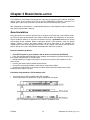
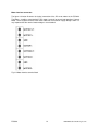
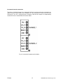
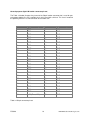
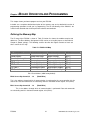
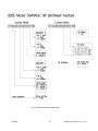
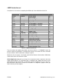
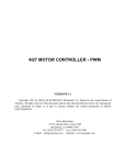
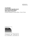
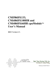
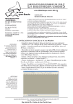
ESC629
2-Channel DC Servo Motor Interface
Board
User’s Manual
BDM- 610020074
ISO9001 and AS9100 Certified
Rev. A
ESC629
2-Channel DC Servo Motor Controller
User’s Manual
RTD Embedded Technologies, INC.
103 Innovation Blvd.
State College, PA 16803-0906
Phone: +1-814-234-8087
FAX: +1-814-234-5218
E-mail
[email protected]
[email protected]
web site
http://www.rtd.com
PC/XT, PC/AT are registered trademarks of IBM Corporation.
PC/104 is a registered trademark of PC/104 Consortium.
The Real Time Devices Logo is a registered trademark of Real Time Devices.
utilityModule is a trademark of Real Time Devices.
All other trademarks appearing in this document are the property of their respective owners.
ESC629
2
RTD Embedded Technologies, Inc
TABLE OF CONTENTS
LIST OF ILLUSTRATIONS AND TABLES ......................................... 5
CHAPTER 1 - INTRODUCTION ......................................................... 6
Features ...................................................................................................................................6
Motion Controllers ....................................................................................................................6
Motor drive stage .....................................................................................................................6
Mechanical description.............................................................................................................7
Connector description ..............................................................................................................7
What comes with your board....................................................................................................7
Board accessories....................................................................................................................7
-Application software and drivers
-Hardware accessories
Using this manual.....................................................................................................................7
When you need help ................................................................................................................8
CHAPTER 2 - BOARD SETTINGS..................................................... 9
Factory-Configured jumper settings .........................................................................................9
Digital I/O Pull Up/Pull Down Jumpers ................................................................................9
Base Address jumpers ......................................................................................................10
Interrupt channels .............................................................................................................11
CHAPTER 3 - BOARD INSTALLATION........................................... 12
Board installation....................................................................................................................12
External I/O connections ........................................................................................................13
-Motor control port I/O connector
-Motor interface connectors
-Incremental encoder connectors
-General purpose digital I/O header connector pin-out
CHAPTER 4 - HARDWARE DESCRIPTION .................................... 17
The LM629 servo controller chips ..........................................................................................18
H-bridges for motion control...............................................................................................18
Incremental encoder inputs ...............................................................................................19
Motor control port ...............................................................................................................19
8255 based digital I/O .......................................................................................................20
CHAPTER 5 - BOARD OPERATION AND PROGRAMMING.......... 21
Defining the memory map ..................................................................................................... 21
LM629 Instruction Set .......................................................................................................... 24
ESC629
3
RTD Embedded Technologies, Inc
-User Command Set reprint from National Semiconductor
Interrupts .............................................................................................................................. 25
What is an interrupt?............................................................................................................. 25
Interrupt request lines ........................................................................................................... 25
8259 Programmable interrupt controller................................................................................ 25
Interrupt mask register (IMR) ................................................................................................ 25
End-Of-Interrupt (EOI) Command ......................................................................................... 26
What exactly happens when an interrupt occurs? ................................................................ 26
Using interrupts in your program ........................................................................................... 26
Writing an interrupt service routine (ISR) .............................................................................. 26
Saving the startup IMR and interrupt vector.......................................................................... 28
Common Interrupt mistakes .................................................................................................. 28
CHAPTER 6 - ESC629 SPECIFICATIONS ...................................... 30
CHAPTER 7 - RETURN POLICY & WARRANTY ............................ 32
ESC629
4
RTD Embedded Technologies, Inc
LIST OF ILLUSTRATIONS AND TABLES
ILLUSTRATIONS
Fig. 2-1:
Fig. 2-2:
Fig. 2-3:
Fig. 3-1:
Fig. 3-2:
Fig. 3-3:
Fig. 4-1:
Fig. 4-2:
Fig. 4-3:
Fig. 5-1:
ESC629 Board layout showing jumper locations
Base address jumpers
Interrupt jumpers
ESC629 integrated with a PC/104 RTD cpuModule stack
Motor interface terminal block.
Incremental encoder terminal blocks
ESC629 Block diagram
Typical motor control scheme
Onboard +12V supply connection solder blob
8255 Control byte bit definition
TABLES
Table 2-1:
Table 2-2:
Table 3-1a:
Table 3-1b:
Table 3-2:
Table 5-1:
Table 5-2:
ESC629
Factory configured jumper settings
Base Address jumper settings of ESC629
Motor control port pin-out of the ESC629
Motor control port pin-out description
50-pin connector pin-out
ESC629 I/O map
LM629 Instruction set
5
RTD Embedded Technologies, Inc
Chapter 1 INTRODUCTION
This user’s manual describes the operation of the ESC629 Embedded Servo Controller board.
Features
Some of the key features of the ESC629 include:
• Two independent Servo Motor controller channels
• Onboard full H-bridges with 10A drive capability, with additional cooling,
6A drive capability with the standard heat sink.
• Direct motor interfaces using onboard terminal blocks
• 2 Independent LM629 PWM-output servo motor controllers
• 2 Protected and filtered incremental encoder inputs
• Control port interfacing to external power driver stage
• 24 user accessible, programmable TTL-level digital I/O (8255 compatible)
• +5V only operation, onboard +12V supply (1A) for external devices
• Supports direct drive of +12V motors from onboard power supply
• PC/104 compliant
• CE approved design
The following paragraphs briefly describe the major features of the ESC629. A more detailed discussion is included in chapter 4 (Hardware description) and in Chapter 5 (Board operation and
programming). The board setup is described in Chapter 2 (Board Settings). A full description of
the LM629 servo controllers is included in Chapter 5 (Board operation and programming).
Motion controllers
The ESC629 DC servo motor interface is implemented using two LM629 controller chips. This
versatile chip offers powerful features that will enable complex positioning tasks with minimal host
intervention. The ESC629 channels can be programmed to operate totally independently offering
a complete subsystem for 2-axis motion control using standard DC motors with encoder feedback
(often called “servo motors”). The LM629 chips include a tunable PID filter, Trajectory control unit
and position counter. These parts perform the intensive real time computational task required in
high performance digital motion control.
Motor drive stage
A powerful onboard H-bridge is used to interface directly to motors. Overvoltage and transient
protection diodes ensure reliable operation in industrial environments. The H-bridges are capable
of driving either 24V or alternatively 48V DC motors. The current drive capability is rated to 10A
peak using the onboard terminal blocks. The ESC629 features a +12V supply with a 500mA output that can be used to drive small +12V motors directly from the board. In this case you do not
need an external power supply for the motors. This onboard power supply is over current limited.
ESC629
6
RTD Embedded Technologies, Inc
Mechanical description
The ESC629 is designed on a PC/104 form factor. An easy mechanical interface to both PC/104
and EUROCARD systems can be achieved. Stack your ESC629 directly on a PC/104 compatible
computer using the onboard mounting holes.
Connector description
There are two 4-position terminal blocks on the left side of the module to directly interfacing to
DC motors. The incremental encoders connect to the ESC629 using small screw terminal
blocks. The general-purpose 50-pin digital I/O interface connector is located on the right hand
side of the board. The 10-pin motor control port header located on the top of the module can be
used to interface to external power output stages.
What comes with your board?
Your ESC629 package contains the following items:
•
•
ESC629 motor interface board
User's manual
Note: Software and drivers are available from our website.
If any item is missing or damaged, please call RTD Embedded Technologies, Inc. customer
service department at the following number: (814) 234-8087.
Board accessories
In addition to the items included in your ESC629 delivery, several hardware accessories are available. Contact your local distributor for more information and for advice on selecting the most appropriate accessories to support your control system. These include the following:
• Software drivers
• Hardware accessories including IDAN solid aluminum mounting frames for PC/104 Computers
For more information on IDAN, please visit our websites at the following internet-address:
www.rtd.com.
Using this manual
This manual is intended to help you install your new ESC629 card and get it working quickly,
while also providing enough detail about the board and its functions so that you can obtain
maximum use of its features even in the most demanding applications. The scope of this manual does not cover complex motion control programming and system design.
ESC629
7
RTD Embedded Technologies, Inc
When you need help
This manual and all the example programs will provide you with enough information to fully utilize all the features on this board. If you have any problems with installation or use of the board,
contact our Technical Support Department +1-814-234-8087 during normal business hours. Alternatively, send a FAX to +1-814-234-5218, or Email to: [email protected] When sending
FAX or Email requests please include the following information: Your company's name and address, your name, your telephone number, and a brief description of the problem.
ESC629
8
RTD Embedded Technologies, Inc
Chapter 2 BOARD SETTINGS
The ESC629 DC servo motor interface board has jumper settings, which can be changed to suit
your application and host computer memory configuration. The factory settings are listed and
shown in the diagram in the beginning of this chapter.
Factory-Configured Jumper Settings
Table 2-1 below illustrates the factory jumper setting for the ESC629. Figure 2-1 shows the
board layout of the ESC629 and the locations of the jumpers. The following paragraphs explain
how to change the factory jumper settings to suit your specific application.
Table 2-1: Factory configured jumper settings (Please check figure 2-1 below for detailed locations)
JUMPER NAME
X10
X11
X13
ADDR
IRQ #1
IRQ #2
DESCRIPTION
Digital I/O Pull-Up
Digital I/O Pull-Up
Digital I/O Pull-Up
Base Addresses
Host interrupt Ch#1
Host interrupt Ch#2
NUMBER OF JUMPERS
2
2
2
4
5
5
FACTORY SETTING
2-3 (Pull Down)
2-3 (Pull Down)
2-3 (Pull Down)
300H
5
11
Figure 2-1: ESC629 Board layout showing jumper locations
Digital I/O Pull Up/Pull Down Jumpers (Factory setting: 2-3)
All digital I/O lines are controlled by a jumper to determine pull up or pull down. If 1-2 is selected
on the jumper it is a 10K ohm pull up, and if 2-3 is selected it is a pull down. The 24 digital I/O
lines are configured as follows.
Jumper “X10” – I/O00 to I/O07
Jumper “X11” – I/O08 to I/O15
Jumper “X13” – I/O16 to I/O23
ESC629
9
RTD Embedded Technologies, Inc
Base Address jumpers (Factory setting: 300h)
The most common cause of failure when you are first setting up your module is address contention. Some of your computer’s I/O-space is already occupied by other internal I/O devices or
expansion boards. When the board attempts to use its own reserved I/O addresses (which are
being already used by another peripheral device), erratic performance may occur and the data
read from the board may be corrupted.
To avoid this problem make sure you set up the base address first using the eight jumpers
marked "BASE”. It allows you to choose from 16 different I/O addresses in your computer’s I/O
map. Should the factory installed setting of 300h be unusable for your system configuration, you
may change this setting to another using the options illustrated in Table 2-2 (overleaf). The table
shows the switch settings and their corresponding values in hexadecimal values. Ensure that
you verify the correct location of the base address jumpers. When the jumper is removed it corresponds to a logical "0", connecting the jumper to a "1". When you set the base address of the
module, record the setting inside the back cover of this manual (directly after the Appendices).
BASE ADDRESS JUMPER SETTINGS OF THE ESC629
BASE ADDRESS (HEX)
A5 A6 A7 A8
200
0
0
0
0
220
1
0
0
0
240
0
1
0
0
260
1
1
0
0
280
0
0
1
0
2A0
1
0
1
0
2C0
0
1
1
0
2E0
1
1
1
0
300
0
0
0
1
320
1
0
0
1
340
0
1
0
1
360
1
1
0
1
380
0
0
1
1
3A0
1
0
1
1
3C0
0
1
1
1
3E0
1
1
1
1
0 = JUMPER OFF
1 = JUMPER CLOSED
Table 2-2: Base Address Jumper settings of the ESC629
ESC629
10
RTD Embedded Technologies, Inc
Fig. 2-2: Base address jumpers illustrating address 300H
Interrupt Channels
(Factory setting: IRQ5 / IRQ11)
The header connectors, shown in Figure 2-3 below, lets you connect the LM629 servo controller
interrupt outputs to one of the interrupt channels available on the host XT/AT bus. If your board
has no AT extension, interrupts 10-15 are not available. Both servo controllers must use different
interrupts and therefore two headers are available. IRQ1 marks the Channel 1 interrupt and IRQ2
marks the interrupt for Channel 2.
Fig. 2-3: Interrupt jumpers
Note: The ESC629 does not support interrupt sharing! This feature is sometimes regarded as a
part of the PC/104 special features. After extensive software and hardware tests we have found
that error-free interrupt performance can not be guaranteed when sharing interrupts.
ESC629
11
RTD Embedded Technologies, Inc
Chapter 3 BOARD INSTALLATION
The ESC629 DC servo motor interface board is very easy to connect to your industrial distributed
control system. Direct interface to PC/104 as well as EUROCARD installations is possible. This
chapter gives step-by-step instructions on how to install the ESC629 into your system.
After completing the installation it is recommended that you use the diagnostic and test software to
fully verify that your board is working.
Board Installation
Keep your board in the antistatic bag until you are ready to install it into your system! When removing it from the bag, hold the board at the edges and do not touch the components or connectors.
Please handle the board in an antistatic environment and use a grounded workbench for testing
and handling of your hardware. Before installing the board in your computer, check the jumper
settings. Chapter 2 reviews the factory settings and how to alter them. If any alterations are
needed, please refer to the appropriate instructions in this chapter. Do however note that incompatible settings can result in unpredictable board operation and erratic response.
General installation guidelines:
• Turn OFF the power to your computer and all devices connected to the ESC629.
• Touch the grounded metal housing of your computer to discharge any antistatic build-up and
then remove the board from its antistatic bag.
• Hold the board by the edges and install it in an enclosure or place it on the table on an antistatic surface.
• Connect your motors to the available terminal blocks.
• Connect the incremental encoders to the correct screw terminal blocks
• Connect the 50-pin digital I/O connector flat-ribbon cable to the board. Make sure that the
orientation of the cables is correct.
Installation integrated with a PC/104 module stack
•
•
Secure the four PC/104 installation holes with standoffs.
Connect the board to its peripherals using the appropriate connectors.
Fig. 3-1: ESC629 integrated into a PC/104 RTD cpuModule stack
ESC629
12
RTD Embedded Technologies, Inc
External I/O Connections
Motor control port I/O connector
Tables 3-1 below, show the connector layout of the ESC629 motor control port J4. This connector is located towards the top of the board. Refer to this diagram when making signal connections.
PIN number
Function (Channel 1)
1
V+ (Either +5V or +12V)
2
GND
3
SIGN_1 (TTL)
4
MAGN_1(TTL)
5
SIGN_2 (TTL)
6
MAGN_2 (TTL)
7
DIR1+ (TTL)
8
DIR1- (TTL)
9
DIR2+ (TTL)
10
DIR2- (TTL)
Table 3-1a: Motor control port pin-out of the ESC629
(+5V is supplied by the PC/104 bus +12V is supplied by a DC/DC converter)
The pin-out of this connector (to view) is shown below:
9
7
5
3
1
DIR2+
DIR1+
Sign_2
Sign_1
V+
DIR2-
DIR1-
Mag_2
Mag_1
GND
10
8
6
4
2
The pins are logically defined as:
V+ (Either +5V or +12V)
Positive supply, selected by B2 on the solder side
1
GND
System ground
2
SIGN_1 (TTL)
Channel 1 Sign signal from LM629 chip (TTL)
3
MAGN_1(TTL)
Channel 1 PWM output signal from LM629 chip (TTL)
4
SIGN_2 (TTL)
Channel 2 Sign signal from LM629 chip (TTL)
5
MAGN_2 (TTL)
Channel 2 PWM output signal from LM629 chip (TTL)
6
DIR1+ (TTL)
Channel 1 direction + (TTL) DIR1+ > DIR1- FORWARD
7
DIR1- (TTL)
Channel 1 direction - (TTL) DIR1+ < DIR1- FORWARD
8
DIR2+ (TTL)
Channel 2 direction + (TTL) DIR2+ > DIR2- FORWARD
9
DIR2- (TTL)
Channel 2 direction - (TTL) DIR2+ < DIR2- FORWARD
10
Table 3-1b: Motor control port pin-out description
ESC629
13
RTD Embedded Technologies, Inc
Motor interface connectors
The figure 3-2 below illustrates the logical connection of the DC-servo motors to the ESC629.
The Motor + should be connected to the DC motor + terminal for correct loop operation. Connect
Motor - to the negative terminal of the motor. Note that the maximum supply voltage is 60V. It is
very important that the nominal motor voltage is not exceeded.
Fig. 3-2 Motor interface terminal block
ESC629
14
RTD Embedded Technologies, Inc
Incremental encoder connectors
The figure 3-3 below illustrates the screw terminal blocks used to connect the incremental encoders of the DC-servo motors to the ESC629. J5 is the connector for Channel #1 and J6 for
Channel #2. The +5V is supplied by the PC/104-bus. Both of these outputs are independently
fused with 2A fuses located under the terminal blocks.
Fig. 3-3 Incremental encoder terminal-blocks
ESC629
15
RTD Embedded Technologies, Inc
General purpose digital I/O header connector pin-out
The Table 3-2 below illustrates the pin-out of the 50-pin header connector that is used for general-purpose digital I/O. +5V is available in pin 49 is fused with a 2A fuse. This fuse is located in
the proximity of the XT PC/104 connector on the solder side.
PIN number
Signal Description
PIN Number
Signal Description
1
PC0
2
N.C
3
PC1
4
GND
5
PC2
6
GND
7
PC3
8
GND
9
PC4
10
GND
11
PC5
12
GND
13
PC6
14
GND
15
PC7
16
GND
17
PB0
18
GND
19
PB1
20
GND
21
PB2
22
GND
23
PB3
24
GND
25
PB4
26
GND
27
PB5
28
GND
29
PB6
30
GND
31
PB7
32
GND
33
PA0
34
GND
35
PA1
36
GND
37
PA2
38
GND
39
PA3
40
GND
41
PA4
42
GND
43
PA5
44
GND
45
PA6
46
GND
47
PA7
48
GND
49
+5V (Fused 2A)
50
GND
Table 3-2 50-pin connector pin-out
ESC629
16
RTD Embedded Technologies, Inc
Chapter 4
HARDWARE DESCRIPTION
This chapter describes in detail the major features of the ESC629:
•
•
•
•
•
•
The LM629 Servo controller chips
H-bridges for motor control
Incremental encoder inputs
Motor control port
8255 based digital I/O
Interrupts
Fig 4-1: ESC629 Block Diagram
ESC629
17
RTD Embedded Technologies, Inc
The LM629 servo controller chips
The LM629 chips are dedicated motion control processors designated for use with a variety of applications using DC Servo motors. These parts perform the complete real-time computational tasks
of complex digital motion control. Included in the chips are three following blocks: 1) a 32-bit command position sequencer, 2) a 32-bit position feedback processor and 3) a 16-bit programmable
PID filter. Figure 4-2 below illustrates the setup for a LM629 based motor control system. The clock
frequency of the controllers is 4MHz. This must be taken into account in all timing calculations.
(8MHz ESC629 boards are also available upon special request)
Fig. 4-2 Typical motor control scheme
Main features of the LM629 include:
•
•
•
•
•
•
•
•
•
32-bit position, velocity and acceleration registers
Programmable PID filter with 16-bit coefficients
Programmable derivative sampling interval
8-bit and sign PWM output
Internal trapezoidal velocity profile generator
Velocity, target position, and filter parameters may be changed during motion
Position and velocity modes of operations
Real-time programmable interrupts
Quadrature encoder feedback with index pulse
H-bridges for motion control
The ESC629 features two independent H-bridges that are used to drive the motors. The H-bridges
are implemented using 4 high performance N-channel MOSFETs. These MOSFETs are configured in two full bridges. Each of the two bridges consists of high side and low-side MOSFETs.
Special full bridge driver chips are used to drive the MOSFET bridges. These drivers can tolerate
negative voltage transients as well as voltages up to 600V. The propagation delay for the high and
low side is also matched to ensure precise control of the bridge. The maximum peak current of the
H-bridge is 25A, 10A continuous with a voltage of 60V maximum with additional heat sinking or
convection cooling with a fan unit such as the EFAN104. If you use the standard heat sink supplied with the ESC629 board you should not exceed 6A continuous current drive.
ESC629
18
RTD Embedded Technologies, Inc
A special low power low motor drive scheme is supported by the ESC629. In this case the motor
power is derived from the onboard +12V supply. Limitations exist in this mode of operation, the
maximum motor voltage is limited to 12V and the aggregate motor current of channels #1 and #2
may not exceed 400mA. The connection of the onboard +12V to the motor eliminates the need for
an external motor supply. This will reduce the wiring and power requirements of the overall system
in low power motor applications. You can connect the +12V onboard supply to the motor channels
by closing the solder blobs B2. Diodes D7 and D6 will protect the DC/DC converter against situations where an external motor power is connected to the board. Figure 4-3 below illustrates the
position of this jumper seen through the PCB from the component side.
Fig. 4-3 Onboard +12V supply connection solder-blob.
The onboard bridge drivers are controlled by signals in the table 3-1b, pins 6-10. These signals are
not TTL level, but 0-12V. The signals can be used to drive an external bridge power element
through the motor control port.
Incremental encoder inputs
The feedback from DC-servo motors is usually implemented using TTL level incremental encoders.
The ESC629 has terminal blocks onboard for direct connection to feedback encoders. The incremental encoders are powered from +5V. This output is protected against over voltages with a special transient absorber diode.
Encoder inputs CH_A, CH_B and INDEX are protected against positive and negative voltage transients. The encoder inputs are fed into a Schmidt trigger buffer that ensures reliable operation even
under noisy environments. Input signals are inverted in this stage. This must be taken into account
when making sensor channel connections. The input impedance of the encoder inputs lines are
4,7K.
Motor control port
The header J4 carries all the necessary signals required to interface to an external power stage.
Available in this connector are power, 8-bit PWM and sign, as well as direct 1/2- bridge control
signals. The power in this connector is selected to be either +12V or +5V. The selection is made
using the solder blob B1 located on the solder side of the board next to the 50-pin connector. This
output is protected with a 2A fuse.
ESC629
19
RTD Embedded Technologies, Inc
8255 based digital I/O
The 8255 programmable peripheral interface (PPI) is used for digital I/O functions. This high performance TTL/CMOS compatible chip has 24 digital I/O lines divided into two groups of 12 lines
each. All digital I/O lines are controlled by a jumper to determine pull up or pull down. See Chapter
2 for factory setting and instructions on use.
Group A:
Group B:
Port A (8) lines and Port C upper (4) lines
Port B (8) lines and Port C lower (4) lines
Port A, Port B and Port C are available in the 50 pin expansion connector. These Ports can be
utilized using any of the three operating modes as described below:
Mode 0:
Basic I/O, this lets you use simple input/output functions for a port. Data is written
to or read from the specified port.
Mode 1:
Strobed input/output. Lets you transfer data I/O from port A in conjunction with
strobed or handshake signals.
Mode 2:
Strobed bi-directional input/output lets you communicate with an external device
through the port A. Handshaking is similar to mode 1.
Available Port direction definitions: Port A and B are defined to be Inputs or Outputs as ports, the
lower bits in Port C, 0-3 and 4-7 may be set as Inputs or Outputs in groups.
All these modes are discussed in detail in the 8255 data sheet available from Intel. In later sections
of this manual an overview of the 8255 chip programming is included.
ESC629
20
RTD Embedded Technologies, Inc
Chapter 5
BOARD OPERATION AND PROGRAMMING
This chapter shows you how to program and use your ESC629.
Included are a complete detailed description of the memory map and a detailed discussion of
programming operations to aid you in programming. The full functionality of the LM629 is described in the attached data sheet reprint from national semiconductor.
Defining the Memory Map
The I/O map of the ESC629 is shown in Table 5-1 below. As shown, the module occupies two
addresses. The Base Address (designated as BA) can be set using the jumpers as described in
Chapter 2 (Board settings). The following sections describe the register contents of each address used in the I/O map.
Table 5-1: ESC629 I/O Map
Register Description
Servo chip #1
Servo chip #2
Board control register
Reserved
PPI Port A
PPI Port B
PPI Port C
PPI Control
Read Function
Reads from chip
Reads from chip
Read control bits
Reserved
Read digital inputs
Read digital inputs
Read digital inputs
Reserved
Write Function
Writes to chip
Writes to chip
Write control bits
Reserved
Write digital outputs
Write digital outputs
Write digital outputs
Write to control byte
Address in HEX
BA+0
BA+1
BA+2
BA+3
BA+4
BA+5
BA+6
BA+7
BA = Base Address (300h factory default)
BA+0 Servo chip channel #1
1-8
(Read/Write)
This is the address through which all communication is performed to the servo controller chip for
channel #1. Data and commands are selected by one bit in the board control register, bit 3 (BA+2).
BA+1 Servo chip channel #2
1-8
(Read/Write)
This is the address through which all communication is performed. Data and commands
are selected by one bit in the board control register, bit 3 (BA+2).
ESC629
21
RTD Embedded Technologies, Inc
BA+2 Board control register
1-4
(Read/Write)
The board control register is used to configure the operation of the ESC629 board. The bit definitions are listed below:
• Bit 0 (0 after reset) /EN_RST, this bit is used to block the host reset from resetting the
servo control chips. In some cases it may be desirable to inhibit a host reset for
example from a watchdog timer to abort a trajectory.
0 -> Enables host reset to reset servo chips
1 -> Disables host reset from resetting servo chips
• Bit 1 (0 after reset)
• Bit 2 (0 after reset)
• Bit 3 (1 after reset)
reserved for factory testing only
reserved for factory testing only
PS, this bit is important for all access to the LM629 chips.
With the PS bit you may select whether you are addressing the chip with commands or data.
This bit must be set before access to the chip is performed to ensure correct interpretation of the
data written to the addresses BA+1 and BA+2. See the software disk for more examples on the
usage of this bit. Please note that when you read from the PS Bit it gives and inverted value.
0 -> DATA
1 - > COMMAND
BA+3
Reserved for factory testing purposes
BA+4 PPI Port A
1-8
(Read/Write)
This port is used to access the 8255 Port A bits. Instructions on how to access port A is described
in greater detail in the software that is included in the shipment. For an exhaustive explanation of
the operation of the 8255 PPI chip please consult the data sheet available from Intel or NEC.
BA+5 PPI Port B
1-8
(Read/Write)
This port is used to access the 8255 Port B bits. Instructions on how to access port A is described
in greater detail in the software that is included in the shipment. For an exhaustive explanation of
the operation of the 8255 PPI chip please consult the data sheet available from Intel or NEC
BA+6 PPI Port C
1-8
(Read/Write)
This port is used to access the 8255 Port C bits. Instructions on how to access port A is described
in greater detail in the software that is included in the shipment. For an exhaustive explanation of
the operation of the 8255 PPI chip please consult the data sheet available from Intel or NEC
BA+7 PPI Control byte 1-8
(Read/Write)
This port is used to access the 8255 control byte. The functionality of these bits is described briefly
in the following page in figure 5-1.
ESC629
22
RTD Embedded Technologies, Inc
Fig. 5-1 8255 Control byte bit definitions
ESC629
23
RTD Embedded Technologies, Inc
LM629 Instruction set
A complete list of instructions accepted by the LM629 chip is described below in table 5-2.
Instruction
RESET
DFH
SIP
LPEI
LPES
SBPA
SBPR
MSKI
RSTI
LFIL
UDF
LTRJ
STT
RDSTAT
RDSIGS
RDIP
RDDP
RDRP
RDDV
RDRV
RDSUM
Type
Initialize
-”-”Interrupt
Interrupt
Interrupt
Interrupt
Interrupt
Interrupt
Filter
Filter
Trajectory
Trajectory
Report
Report
Report
Report
Report
Report
Report
Report
Description
Reset LM629
Define Home
Set Index Position
Interrupt on Error
Stop on Error
Set Breakpoint , Absolute
Set Breakpoint , Relative
Mask Interrupts
Reset Interrupts
Load Filter Parameters
Update Filter
Load Trajectory
Start Motion
Read Status Byte
Read Signals Register
Read Index Position
Read Desired Position
Read Desired Position
Read Desired Velocity
Read Real Velocity
Read Integration Sum
HEX
00
02
03
1B
1A
20
21
1C
1D
1E
04
1F
01
None
0C
09
08
0A
07
0B
0D
Table 5-2: LM629 Instruction Set
These instructions are loaded to the LM629 chip while the PS-bit is in “COMMAND” mode. See
previous sections for more details. The board status register can be read at all times, remember
to set the PS-bit in “DATA” mode when reading this register.
Attached on the next pages is description reprinted from National Semiconductor LM629 data
sheet that describes the commands in detail.
AN-639 Application note walks you through all the important functions required to solve most
motion control problems. This application note is included on your software disk and it can be
downloaded from www.national.com. The diagnostic program “diag629.exe” has the same functions described in flow charts in AN-639 as C-functions. This diagnostics program shows you
how to correctly use them together.
ESC629
24
RTD Embedded Technologies, Inc
User Command-set, reprinted from National Semiconductor datasheet
INTERRUPTS
What is an interrupt?
An interrupt is an event that causes the processor in your computer to temporarily halt its current
process and execute another routine. Upon completion of the new routine, control is returned to
the original routine at the point where its execution was interrupted.
Interrupts are a very flexible way of dealing with asynchronous events. Keyboard activity is a good
example; your computer cannot predict when you might press a key and it would be a waste of
processor time to do nothing whilst waiting for a keystroke to occur. Thus the interrupt scheme is
used and the processor proceeds with other tasks. When a keystroke finally occurs, the keyboard
then 'interrupts' the processor so that it can get the keyboard data .It then places it into the memory, and then returns to what it was doing before the interrupt occurred. Other common devices
that use interrupts are A/D boards, network boards, serial ports etc.
Your ESC629 can interrupt the main processor when a trajectory is completed, motor is stopped
or an error occurs in the motor control process. A complete description of all the possible error
condition interrupts is included in the documentation of the LM629 chip. By using interrupts you
can write powerful code to interface to your motion control system.
Interrupt request lines
To allow different peripheral devices to generate interrupts on the same computer, the PC AT bus
has interrupt request channels (IRQ's). A rising edge transition on one of these lines will be
latched into the interrupt controller. The interrupt controller checks to see if the interrupts are to be
acknowledged from that IRQ and, if another interrupt is being processed, it decides if the new
request should supersede the one in progress or if it has to wait until the one in progress has
been completed. The priority level of the interrupt is determined by the number of the IRQ as follows; IRQ0 has the highest priority whilst IRQ15 has the lowest. Many of the IRQ's are used by the
standard system resources, IRQ0 is dedicated to the internal timer, IRQ1 is dedicated to the keyboard input, IRQ3 for the serial port COM2, and IRQ4 for the serial port COM1. Often interrupts 5
and 7 are free for the user.
8259 Programmable Interrupt Controller
The chip responsible for handling interrupt requests in a PC is the 8259 Interrupt Controller. To
use interrupts you will need to know how to read and set the 8259's internal interrupt mask register (IMR) and how to send the end-of-interrupt (EOI) command to acknowledge the 8259 interrupt
controller.
Interrupt Mask Register (IMR)
Each bit in the interrupt mask register (IMR) contains the mask status of the interrupt line. If a bit
is set (equal to 1), then the corresponding IRQ is masked, and it will not generate an interrupt. If a
bit is cleared (equal to 0), then the corresponding IRQ is not masked, and it can then generate an
interrupt. The interrupt mask register is programmed through port 21h.
ESC629
25
RTD Embedded Technologies, Inc
End-of-Interrupt (EOI) Command
After an interrupt service routine is complete, the 8259 Interrupt Controller must be acknowledged
by writing the value 20h to port 20h.
What exactly happens when an interrupt occurs?
Understanding the sequence of events when an interrupt is triggered is necessary to correctly
write interrupt handlers. When an interrupt request line is driven high by a peripheral device (such
as the ESC629), the interrupt controller checks to see if interrupts are enabled for that IRQ. It then
checks to see if other interrupts are active or requested and determines which interrupt has priority. The interrupt controller then interrupts the processor. The current code segment (CS), instruction pointer (IP), and flags are pushed onto the system stack, and a new set if CS and IP are
loaded from the lowest 1024 bytes of memory.
This table is referred to as the interrupt vector table and each entry to this table is called an interrupt vector. Once the new CS and IP are loaded from the interrupt vector table, the processor
starts to execute code from the new Code Segment (CS) and from the new Instruction Pointer
(IP). When the interrupt routine is completed the old CS and IP is popped from the system stack
and the program execution continues from the point where interruption occurred.
Using Interrupts in your Program
Adding interrupt support to your program is not as difficult as it may seem especially when programming under DOS. The following discussion will cover programming under DOS. Note that
even the smallest mistake in your interrupt program may cause the computer to hang up and will
only restart after a reboot. This can be frustrating and time-consuming.
Writing an Interrupt Service Routine (ISR)
The first step in adding interrupts to your software is to write an interrupt service routine (ISR).
This is the routine that will be executed automatically each time an interrupt request occurs for the
specified IRQ. An ISR is different from other sub-routines or procedures. First, on entrance the
processor registers must be pushed onto the stack before anything else! Second, just before exiting the routine, you must clear the interrupt on the ESC629 by issuing the RSTI instruction and
reading the interrupt status register, and finally write the EOC command to the interrupt controller.
When exiting the interrupt routine the processor registers must be popped from the system stack
and you must execute the IRE assembly instruction. This instruction pops the CS, IP and processor flags from the system stack. These were pushed onto the stack when entering the ISR.
ESC629
26
RTD Embedded Technologies, Inc
Most compilers allow you to identify a function as an interrupt type and will automatically add these
instructions to your ISR with one exception: most compilers do not automatically add the EOI
command to the function, you must do it yourself. Other than this and a few exceptions discussed
below, you can write your ISR as any code routine. It can call other functions and procedures in
your program and it can access global data. If you are writing your first ISR, we recommend you
stick to the basics; just something that enables you to verify you have entered the ISR and executed it successfully. For example: set a flag in your ISR and in your main program check for the
flag.
Note:
If you choose to write your ISR in in-line Assembly, you must push and pop registers
correctly and exit the routine with the IRET instruction instead of the RET instruction.
There are a few precautions you must consider when writing ISR's. The most important is do not
use any DOS functions or functions that call DOS functions from an interrupt routine. DOS
is not re-entrant; that is, a DOS function cannot call itself. In typical programming, this will not
happen because of the way DOS is written. But what about using interrupts? Consider then the
following situation in your program: If DOS function X is being executed when an interrupt occurs
and the interrupt routine makes a call to the same DOS function X, then function X is essentially
being called while active. Such cases will cause the computer to crash. DOS does not support
such operations. The general rule is that do not call any functions that use the screen, read keyboard input or any file I/O routines. These should not be used in ISR's.
The same problem of re-reentrancy also exists for many floating-point emulators. This effectively
means that you should also avoid floating point mathematical operations in your ISR.
Note that the problem of reentrancy exists, no matter what programming language you use. Even,
if you are writing your ISR in Assembly language, DOS and many floating point emulators are not
re-entrant. Of course there are ways to avoid this problem, such as those which activate when
your ISR is called. Such solutions are, however, beyond the scope of this manual.
The second major concern when writing ISR's is to make them as short as possible in term of
execution time. Spending long times in interrupt service routines may mean that other important
interrupts are not serviced. Also, if you spend too long in your ISR, it may be called again before
you have exited. This will lead to your computer hanging up and will require a reboot.
Your ISR should have the following structure:
•
•
•
•
•
•
Push any processor registers used in your ISR. Most C compiler do this automatically
Put the body of your routine here
Read interrupt status register of the LM629 chip on your ESC629 board
Clear the interrupt bit by writing the RSTI instruction to the LM629 that caused the interrupt
Issue the EOI command to the 8259 by writing 20h to address 20h
Pop all registers. Most C compilers do this automatically
The following C example shows what the shell of your ISR should be like:
/*------------------------------------------------------------------------------| Function:
new_IRQ_handler
| Inputs:
Nothing
| Returns:
Nothing - Sets the interrupt flag for the EVENT.
|-------------------------------------------------------------------------------*/
void interrupt far new_IRQ_handler(void)
ESC629
27
RTD Embedded Technologies, Inc
{
IRQ_flag = 1;
// Indicate to main process interrupt has occurred
{
// Your program code should be here
}
// Read interrupt status registers
// Clear interrupt on ESC629
outp(0x20, 0x20);
/* Acknowledge the interrupt controller. */
}
Saving the Startup Interrupt Mask Register (IMR) and interrupt vector
The next step after writing the ISR is to save the start up state of the interrupt mask register, and
the original interrupt vector you are using. The IMR is located in address 21h. The interrupt vector
you will be using is located in the interrupt vector table which is an array of pointers (addresses)
and it is locate din the first 1024 bytes of the memory (Segment 0 offset 0). You can read this
value directly, but it is a better practice to use DOS-function 35h (get interrupt vector) to do this.
Most C compilers have a special function available for doing this. The vectors for the hardware
interrupts on the XT - bus are vectors 8-15, where IRQ0 uses vector 8 and IRQ7 uses vector 15.
Thus if your ESC629 is using IRQ5 it corresponds to vector number 13.
Before you install your ISR, temporarily mask out the IRQ you will be using. This prevents the IRQ
from requesting an interrupt while you are installing and initializing your ISR. To mask the IRQ,
read the current IMR at I/O port 21h, and set the bit that corresponds to the IRQ. The IMR is arranged so that bit 0 is for IRQ0 and bit 7 is for IRQ7. See the paragraph entitled Interrupt Mask
Register (IMR) earlier in this discussion for help in determining your IRQ's bit. After setting the bit,
write the new value to I/O port 21h.
With the startup IMR saved and the interrupts temporarily disabled, you can assign the interrupt
vector to point to your ISR. Again you can overwrite the appropriate entry in the vector table with a
direct memory write, but this is not recommended. Instead use the DOS function 25h (Set Interrupt Vector) or, if your compiler provides it, the library routine for setting up interrupt vectors. Remember that interrupt vector 8 corresponds to IRQ0, vector 9 for IRQ1 etc.
If you need to program the source of your interrupts, do that next. For example, if you are using
transmitted or received messages as interrupt source, program it to do that. Finally, clear the
mask bit for your IRQ in the IMR. This will enable your IRQ.
Common Interrupt mistakes
Remember hardware interrupts are from 8-15, XT IRQ's are numbered 0-7. Forgetting to clear the
IRQ mask bit in the IMR Forgetting to send the EOI command after ISR code. Disables further
interrupts.
Example on Interrupt vector table setup in C-code:
void far _interrupt new_IRQ1_handler(void );
#define IRQ1_VECTOR 3
void (interrupt far *old_IRQ1_dispatcher)
/* ISR function prototype */
/* Name for IRQ */
ESC629
28
RTD Embedded Technologies, Inc
(es,ds,di,si,bp,sp,bx,dx,cx,ax,ip,cs,flags);
void far _interrupt new_IRQ1_handler(void );
/* Variable to store old IRQ_Vector */
/*---------------------------------------------------------------------| Function:
init_irq_handlers
| Inputs: Nothing
| Returns:
Nothing
| Purpose:
Set the pointers in the interrupt table to point to
|
our functions i.e. setup for ISR's.
|----------------------------------------------------------------------*/
void init_irq_handlers(void)
{
_disable();
old_IRQ1_handler = _dos_getvect(IRQ1_VECTOR + 8);
_dos_setvect(IRQ1_VECTOR + 8, new_IRQ1_handler);
Gi_old_mask = inp(0x21);
outp(0x21,Gi_old_mask & ~(1 << IRQ1_VECTOR));
_enable();
}
|/*---------------------------------------------------------------------| Function:
Restore, do this before exiting program
| Inputs: Nothing
| Returns:
Nothing
| Purpose:
Restore interrupt vector table.
|----------------------------------------------------------------------*/
void restore(void)
{
/* Restore the old vectors */
_disable();
_dos_setvect(IRQ1_VECTOR + 8, old_IRQ1_handler);
outp(0x21,Gi_old_mask);
_enable();
}
ESC629
29
RTD Embedded Technologies, Inc
Chapter 6 ESC629 SPECIFICATIONS
Host Interface
I/O mapped, occupies 16 bytes of space
Jumper-selectable base address with 4 jumpers
8-bit data bus, 16-bit AT bus connector
Jumper selectable interrupts, both XT and AT: 5, 7, 10, 11, 12
Servo controllers and H-bridge
LM629 servo controllers
Position range
-1,073,741,824 to 1,073,741,823 counts
Velocity range
0 to 1,073,741,823/2 EXP 16 counts/sample i.e. 0 to 16368 counts per sample
with 1/2 EXP16 counts/sample resolution
Acceleration range
0 to 1,073,741,823/2 EXP 16 counts/sample/sample i.e. 0 to 16368
counts/sample2 with 1/2 EXP16 counts/sample resolution
Motor drive output
8-bit PWM, sign/magnitude signals
Operating Modes
Position and Velocity
Feedback Device
Quadrature signals , index pulse, TTL level signals
Control Algorithm
PID with programmable integration limit
Sample Intervals
Derivative term programmable from 2048/Fclk to
2048*2048/Fclk 256 to 65,536us
Clock Frequency
4 MHz (8MHz also available upon request)
H-bridge
Max. voltage
60V DC
Max. cont. current
10A, 6A with supplied standard heat sink.
Peak current
25A
Output capacitors
220uF / 63V for each channel
Protection
60V transient absorber diodes 1500W power dissipation
ESC629
30
RTD Embedded Technologies, Inc
8255 Digital I/O
TTL/CMOS levels
Number of lines
24
Drive capability
2mA
Pull-up /Pull-down
10K pull-down on all 24 lines
Connectors
Motors, cable connector
Phoenix contact MSTB 2,5/ 4-ST-5,08
Motors, PCB connector
MSTB 2,5/ 4-G-5,08
Encoder feedback connector MPT 0,5/ 5-2,54
Motor control port
10-pin headers
TTL digital I/O’s
Header connector 50-Pin
Host bus
XT/AT PC/104 bus
Electrical
Operating temperature ranges
+0 to +70 C
-40 to +85 C
Supply voltage
+5V, +-8%
Power consumption
2,0 W maximum with +12V output unloaded
+12V power supply
Max load 1A
Mechanical
PCB size
91 x 96 mm
MAX size
110 x 96 x 17 mm (non stack through connectors)
CE
The ESC629 is CE certified in the IDAN Enclosure System.
ESC629
31
RTD Embedded Technologies, Inc
Chapter 7 RETURN POLICY AND WARRANTY
Return Policy
If you wish to return a product to the factory for service, please follow this procedure:
Read the Limited Warranty to familiarize yourself with our warranty policy.
Contact the factory for a Return Merchandise Authorization (RMA) number.
Please have the following available:
•
•
•
Complete board name
Board serial number
A detailed description of the board’s behavior
List the name of a contact person, familiar with technical details of the problem or situation, along
with their phone and fax numbers, address, and e-mail address (if available).
List your shipping address!!
Indicate the shipping method you would like used to return the product to you.
We will not ship by next-day service without your pre-approval.
Carefully package the product, using proper anti-static packaging.
Write the RMA number in large (1") letters on the outside of the package.
Return the package to:
RTD Embedded Technologies, Inc.
103 Innovation Blvd.
State College PA 16803-0906
USA
ESC629
32
RTD Embedded Technologies, Inc
Limited Warranty
RTD Embedded Technologies, Inc. warrants the hardware and software products it manufactures and produces to be
free from defects in materials and workmanship for one year following the date of shipment from RTD Embedded
Technologies, INC. This warranty is limited to the original purchaser of product and is not transferable.
During the one year warranty period, RTD Embedded Technologies will repair or replace, at its option, any defective
products or parts at no additional charge, provided that the product is returned, shipping prepaid, to RTD Embedded
Technologies. All replaced parts and products become the property of RTD Embedded Technologies. Before returning any product for repair, customers are required to contact the factory for an RMA number.
THIS LIMITED WARRANTY DOES NOT EXTEND TO ANY PRODUCTS WHICH HAVE BEEN DAMAGED
AS A RESULT OF ACCIDENT, MISUSE, ABUSE (such as: use of incorrect input voltages, improper or insufficient ventilation, failure to follow the operating instructions that are provided by RTD Embedded Technologies,
"acts of God" or other contingencies beyond the control of RTD Embedded Technologies), OR AS A RESULT OF
SERVICE OR MODIFICATION BY ANYONE OTHER THAN RTD Embedded Technologies. EXCEPT AS
EXPRESSLY SET FORTH ABOVE, NO OTHER WARRANTIES ARE EXPRESSED OR IMPLIED,
INCLUDING, BUT NOT LIMITED TO, ANY IMPLIED WARRANTIES OF MERCHANTABILITY AND FITNESS FOR A PARTICULAR PURPOSE, AND RTD Embedded Technologies EXPRESSLY DISCLAIMS ALL
WARRANTIES NOT STATED HEREIN. ALL IMPLIED WARRANTIES, INCLUDING IMPLIED
WARRANTIES FOR MECHANTABILITY AND FITNESS FOR A PARTICULAR PURPOSE, ARE LIMITED
TO THE DURATION OF THIS WARRANTY. IN THE EVENT THE PRODUCT IS NOT FREE FROM
DEFECTS AS WARRANTED ABOVE, THE PURCHASER'S SOLE REMEDY SHALL BE REPAIR OR
REPLACEMENT AS PROVIDED ABOVE. UNDER NO CIRCUMSTANCES WILL RTD Embedded Technologies BE LIABLE TO THE PURCHASER OR ANY USER FOR ANY DAMAGES, INCLUDING ANY INCIDENTAL OR CONSEQUENTIAL DAMAGES, EXPENSES, LOST PROFITS, LOST SAVINGS, OR OTHER
DAMAGES ARISING OUT OF THE USE OR INABILITY TO USE THE PRODUCT.
SOME STATES DO NOT ALLOW THE EXCLUSION OR LIMITATION OF INCIDENTAL OR
CONSEQUENTIAL DAMAGES FOR CONSUMER PRODUCTS, AND SOME STATES DO NOT ALLOW
LIMITATIONS ON HOW LONG AN IMPLIED WARRANTY LASTS, SO THE ABOVE LIMITATIONS OR
EXCLUSIONS MAY NOT APPLY TO YOU.
THIS WARRANTY GIVES YOU SPECIFIC LEGAL RIGHTS, AND YOU MAY ALSO HAVE
OTHER RIGHTS WHICH VARY FROM STATE TO STATE.
ESC629
33
RTD Embedded Technologies, Inc