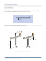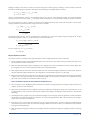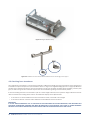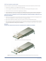
1
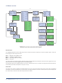
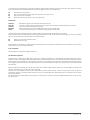
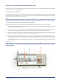
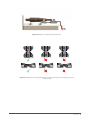
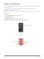
SINGLE WIRE MYOGRAPH SYSTEM
MODEL 310A
User Manual
Version 3.5
1
2
WIRE MYOGRAPH SYSTEM - MODEL 310A USER MANUAL
SINGLE WIRE MYOGRAPH SYSTEM
MODEL 310A
TRADEMARKS
PowerLab® and LabChart® are registered trademarks of ADInstruments Pty Ltd.
The names of specific recording units, such as PowerLab 4/25, are trademarks of ADInstruments Pty Ltd.
Pentium is a registered trademark of the Intel Corporation. Windows, Windows 95, Windows 98, Windows ME, Windows NT,
Windows 2000, Windows XP and Vista are registered trademarks of Microsoft Corporation.
All other trademarks are the properties of their respective owners.
DMT reserves the right to alter specifications as required.
This document was, as far as possible, accurate at the time of printing.
Changes may have been made to the software and hardware it describes since then.
New information may be supplied separately.
This documentation is provided with the DMT Single wire myograph system – Model 310A
Document Number: 310A – UG3.3A
All rights reserved. No part of this manual may be reproduced or transmitted in any form or by any means
without the written permission of Danish Myo Technology A/S.
Every attempt is made to ensure accurate information, misprints, construction- and specification changes can occur.
Danish Myo Technology A/S reserves the right to alter/change content as required and without any notice.
Copyright © Danish Myo Technology A/S
TRADEMARKS
3
CONTENTS
Trademarks.........................................................................................................................................................................................3
Introduction ........................................................................................................................................................................................5
Safety ..................................................................................................................................................................................................6
EMC / EMI ..........................................................................................................................................................................................7
Approvals ............................................................................................................................................................................................7
Certificate of Conformity...................................................................................................................................................................8
About this manual..............................................................................................................................................................................9
Unpacking the myograph system .................................................................................................................................................. 10
Chapter 1 - System overview ......................................................................................................................................................... 11
1.1 Myo-Interface front panel ............................................................................................................................................................... 11
1.2 Myo-Interface rear panel................................................................................................................................................................ 11
1.3 Single Wire Myograph Unit............................................................................................................................................................. 12
Chapter 2 - Setting-up .................................................................................................................................................................... 13
2.1 The complete myograph 310A system .......................................................................................................................................... 13
2.2 Setting up step-by-step .................................................................................................................................................................. 13
2.3 The force transducer calibration ................................................................................................................................................... 14
Chapter 3 - The Myo-Interface ....................................................................................................................................................... 15
3.1 Turning on the Myo-Interface ......................................................................................................................................................... 15
3.2 Menus and submenus ................................................................................................................................................................... 15
3.3 Menu overview................................................................................................................................................................................ 16
Chapter 4 - The Single Wire Myograph unit .................................................................................................................................. 18
4.1 Adjustment of supports.................................................................................................................................................................. 18
4.2 Force transducer calibration.......................................................................................................................................................... 20
4.3 Checking force transducer ............................................................................................................................................................. 22
4.4 Force transducer replacement ...................................................................................................................................................... 23
4.5 Changing the myograph window glass .......................................................................................................................................... 24
4.6 Myograph maintenance and cleaning .......................................................................................................................................... 24
Appendix 1 - Fuse replacement ..................................................................................................................................................... 27
Appendix 2 - System specifications .............................................................................................................................................. 28
Notes ................................................................................................................................................................................................ 29
4
WIRE MYOGRAPH SYSTEM - MODEL 310A USER MANUAL
INTRODUCTION
Until the mid-1970s most of the details about the mechanical, morphological and pharmacological properties of vascular smooth
muscle was obtained from studies on relatively large vessels. At that time, rat tail arteries were the smallest vessels to be
investigated in detail due to limitations in the available in vitro techniques. For example, studies measuring the contraction
force were routinely performed with only one of the mounting wires secured. Furthermore, relatively large wires (100–200 μm)
were used, which precluded the use of small vessels, and the vessel segment had to be directly manipulated with the dissecting
equipment causing inevitable mechanical trauma. Investigations of smaller vessels were therefore limited to in vivo perfusion
experiments and histological examinations.
In 1976, Professors Mulvany and Halpern described for the first time a new technique that made it possible to investigate highlyisometric responses from vessels with internal diameters as small as 100 μm. The mounting procedure was refined twofold:
both ends of each mounting wire were secured under tension without any direct manipulation of the vessel segment. Segments
of small vessels could now be atraumatically mounted as ring preparations in a myograph for recording of highly isometric force
measurements.
During the late 1970s some improvements were made to the myograph and in 1981 a new dual myograph that allowed
simultaneous testing of two vessels was introduced. In parallel, the technique became widely acknowledged resulting in a
growing interest in the myograph systems. In 1986, the growing demand resulted in the foundation of the private company
J.P. Trading with the purpose of making the myograph systems commercially available worldwide. At the same time J.P. Trading
initiated a comprehensive improvement programme for the existing myograph systems as well as a development programme of
new myograph systems in close co-operation with Professor M. J. Mulvany and the University of Aarhus.
During the late 1980s and through the 1990s several improvements were applied to the myograph systems, such as a new
mechanical design, a more robust transducer and new electronic systems. In addition, new systems were introduced, like the
Automatic Dual Myograph 510A, the Dual Myograph 410A, the Multi Myograph 620M and the Confocal Myograph 120CW. In
2000 J.P. Trading changed its company structure and became known as DMT - Danish Myo Technology A/S.
Today DMT is one of the world’s leading designers and manufacturers of wire myographs, pressure myographs, culture myographs
and organ/tissue baths. Driven by our global customer base, our number one goal is to develop and manufacture first class
research equipment within the fields of physiology and pharmacology.
INTRODUCTION
5
SAFETY
The Single Wire Myograph System has been designed for use only in teaching and research applications. It is not intended for
clinical or critical life-care use and should never be used for these purposes: nor for the prevention, diagnosis, curing, treatment,
or alleviation of disease, injury, or handicap.
• Do not open the unit: the internal electronics pose a risk of electric shock.
• Do not use this apparatus near water.
• To reduce the risk of fire or electric shock, do not expose this apparatus to rain or moisture. Objects filled with liquids should
not be placed on the apparatus.
• Do not block any ventilation openings. Install in accordance with the manufacturer’s instructions.
• Do not install near any heat sources such as radiators, heat registers, stoves, or other apparatus that produce heat.
• Only use attachments and accessories specified by the manufacturer.
• Unplug this apparatus during lightning storms or when unused for long periods of time.
• This apparatus must be grounded.
• Use a three-wire grounding-type cord similar to the one supplied with the product.
• Do not defeat the safety purpose of the polarized or grounding-type plug. A polarized plug has two flat blades, one being
wider than the other. A grounding type plug has two blades and a third (round) grounding pin. The wide blade or the third
prong is provided for your safety. If the provided plug does not fit into your outlet, consult an electrician for replacement of
the obsolete outlet.
• Be advised that different operating voltages require the use of different types of line cord and attachment plugs. Check the
voltage in your area and use the correct type. See the table below:
Voltage
Line plug according to standard
110–125 V
UL817 and CSA C22.2 No. 42
220–230 V
CEE 7 page VII, SR section 107-2-D1/IEC 83, page C4
240 V
BS 1363 of 1984. Specification for 13A fused plugs and switched and
unswitched socket outlets.
Protect the power cord from being walked on or pinched: particularly at power plugs and the point where they connect to the
apparatus.
Refer all servicing to qualified service personnel. Servicing is required when the apparatus has been damaged in any way; such
as, the power-supply cord or plug is damaged, liquid has spilled onto or objects have fallen into the apparatus, the apparatus has
been exposed to rain or moisture, does not operate normally, or has been dropped.
6
WIRE MYOGRAPH SYSTEM - MODEL 310A USER MANUAL
EMC / EMI
This equipment has been tested and found to comply with the limits for a Class B Digital device, pursuant to part 15 of the
FCC rules. These limits are designed to provide reasonable protection against harmful interference in residential installations.
This equipment generates, uses and can radiate radio frequency energy and, if not installed and used in accordance with the
instructions, may cause harmful interference to radio communications. However, there is no guarantee that interference will not
occur in a particular installation. If this equipment does cause harmful interference to radio or television reception (which can
be determined by monitoring the interference while turning the equipment off and on), the user is encouraged to correct the
interference by one or more of the following measures:
• Reorient or relocate the receiving antenna.
• Increase the separation between the equipment and receiver.
• Connect the equipment into an outlet on a circuit different to that which the receiver is connected to.
• Consult the dealer or an experienced radio/TV technician for help.
APPROVALS
Complies with the EMC standards:
EMC 89/336/EEC:
Certified with the safety standards:
Directive 2006/95/EC:
EN 61326-2-6:2005
EN 61000-3-2.
EN 61010-1:2001
EN 61010-1/Corr.1:2003
EN 61010-1/Corr.1:2003
EN 61010-2-101:2003
EMC/EMI
7
CERTIFICATE OF CONFORMITY
DMT A/S, Skejbyparken 152, 8200 Aarhus N., Denmark,
hereby declares its responsibility that the following product:
Single Wire Myograph System - Model 310A
is covered by this certificate and marked with CE-label conforms with the following standards:
EN 61010-1:2001
EN61010-1/Corr.1:2003
EN 61010-1/Corr.1:2003
Safety requirements for electrical equipment for measurement,
control, and laboratory use Part 1: General requirements.
EN 61010-2-101:2003
Safety requirements for electrical equipment for measurement,
control and laboratory use - Part 2-101: Particular requirements for
in vitro diagnostic (IVD) medical equipment.
EN 61326-2-6:2005
Electrical equipment for measurement, control and laboratory use
- EMC requirements - Part 2-6: Particular requirements - In vitro diagnostic (IVD) medical equipment.
With reference to regulations in the following directives: 2006/95/
EC, 89/336/EEC
8
WIRE MYOGRAPH SYSTEM - MODEL 310A USER MANUAL
ABOUT THIS MANUAL
This manual contains a complete list of procedures describing how to install, maintain and using the Single Wire Myograph System – model 310A.
Chapter 1 provides an overview of the construction and basic features of the Myo-Interface and the single wire myograph unit.
Chapter 2 describes step-by-step how to set-up a complete 310A wire myograph system including accessories.
Chapter 3 is a complete manual to the 310A Myo-Interface, version 3.3. The chapter contains a step-by-step description of how
to navigate in the menus and how to use the special features of a 310A myograph.
Chapter 4 contains procedures describing general as well as daily maintenance of the myograph unit; e.g. adjustment of supports, weight calibration of the force transducer and cleaning instructions.
Appendices contain additional information such as fuse replacement and system specification.
ABOUT THIS MANUAL
9
UNPACKING THE MYOGRAPH SYSTEM
Please take a few minutes to carefully inspect your new wire myograph system for damage, which may have occurred during
handling and shipping. If you suspect any kind of damage, please contact DMT immediately and the matter will be pursued as
quickly as possible. If the packing material appears damaged, please retain it until a possible claim has been settled.
We recommend that you store the packing material for any possible future transport of the Wire Myograph System. In case of
transport and the original packing material is unavailable, please contact the DMT Sales Department for advice and packing
instructions.
After unpacking your new Wire Myograph System, please use the following list to check that the system is complete:
1. Myo-Interface:
• Myograph connection cable with a temperature probe
• Power cord (the shape of the AC plug varies by country; be sure that the plug has the right shape for your location)
2. Single wire myograph unit:
• Calibration kit (including bridge, balance and 2 g weight)
• Chamber cover
• Chamber separator
3. Accessories:
• 1 roll of stainless steel wire (40 µm diameter)
• 1 tube of high vacuum grease
• 1 tube of grease for linear slides
• 4 spare screws for mounting of jaws
• 2 Allen keys
• 1 small screwdriver
4. Manuals
• 1 CD with user manuals for Wire Myograph Systems
• 1 CD with the manual “Procedures for investigation of small vessels using small vessel myograph”, by Professor M. J.
Mulvany, Department of Pharmacology, Aarhus University, Denmark and the video “Dissection and mounting of small
vessels in wire myographs”
10
WIRE MYOGRAPH SYSTEM - MODEL 310A USER MANUAL
CHAPTER 1 - SYSTEM OVERVIEW
1.1 Myo-Interface front panel
Analog recorder output - Connection to external
data acquisition system (optional)
Up and down arrow keys - Scroll up and down in the menus.
Myo-Interface display
MYO INTERFACE
MYO
INTERFACE
MODEL
310A
MODEL
310A
VERSION 3.25
VERSION
3.30
F1
F2
F3
F4
Info
Esc
Enter
F-keys - Have different but specific functions dependent of the active main menu
1
2
3
Rec. 1
4
5
6
Rec. 2
7
8
9
Rec. 3
-
0
.
Rec. 4
Numeric keys Enter data or setting values
INFO key - Push this key in any menu to
display all specific F-key functions
Enter key - Confirm entered numeric values or
change between available choices
Esc key - Delete incorrectly entered numeric
values. In some submenus used to return to
main menu
Figure 1.1 Myo-Interface front panel
1.2 Myo-Interface rear panel
115-230 V / 50-60 Hz automatic voltage selector
ON/OFF switch
Power connector
O
I
USB
REGULATOR
RS232
ON
1 2
12V DC
pH
MYOGRAPH
Connection port for 310A
Myograph unit
Regulator port for electronic
valve (optional)
RS 232 port for serial connection to PC
Connection port for pH-Meter (optional)
12V DC port
USB port
Figure 1.2 Myo-Interface rear panel
CHAPTER 1 11
1.3 Single Wire Myograph Unit
Port for connection to Myo-Interface
Four Allen screws for fine alignment of the myograph jaws
Transducer house
Pipe for gas supply
Micrometer
Pipe for filling the
myograph chamber
using the 40 mm funnel)
Suction pipe for connection to vacuum pump
Myograph jaw connected
to micrometer
Myograph jaw connected to force
transducer
Force transducer pin
Window at the bottom of the myograph chamber for imaging
Figure 1.3 Single Wire Myograph Unit
12
WIRE MYOGRAPH SYSTEM - MODEL 310A USER MANUAL
CHAPTER 2 - SETTING-UP
2.1 The complete myograph 310A system
Power supply
Myo-Interface front panel
MYO INTERFACE
F1
F2
F3
F4
Info
Esc
Enter
1
2
3
Rec. 1
4
5
6
Rec. 2
7
8
9
Rec. 3
-
0
.
Rec. 4
PC data acquisition and analysis
software (optional)
PowerLab data acquisition system
(optional)
BNC Cables
PC USB Connection
Myo-Interface rear panel
Connection cable with temp. probe
230V
O
I
USB
REGULATOR
RS232
ON
1 2
12V DC
pH
MYOGRAPH
pH-meter
(optional)
Vacuum pump
(optional)
Myograph unit
Power supply
Electronic valve
(optional)
Suction bottle
Connection to oxygen supply
Figure 2.1 The complete single wire myograph system - model 310A
2.2 Setting up step-by-step
The chapter contains a complete step-by-step description of how to set up a complete Myograph 310A System as illustrated in
figure 2.1 above.
1. Myograph unit – Myo-Interface connection:
Connect the myograph 310A unit to the Myo-Interface using the grey 25-pin connection cable. The end of the cable with the
temperature probe is used with the myograph unit.
2. Myo-Interface – PC connection:
Data acquisition is possible either by connecting the Myo-Interface directly to a PC or through a PowerLab data acquisition
and analysis system (optional).
I.
Direct PC Connection:
Connect the Myo-Interface via the RS 232 port to one of the COM-ports on the PC using a serial cable. Note that the
310A Myo-Interface has baud rates of 9600 and 19200 available (entered in the Setup menu).
II. PowerLab (optional):
Connect the Myo-Interface to the PowerLab unit using BNC cables. Connect Rec 1 on the Myo-Interface to Input 1 on
the PowerLab. Rec 2 to Input 2, and so forth.
Connect the PowerLab unit to one of the USB-ports on the PC using the USB cable delivered with the PowerLab system.
3. Gas supply:
Connect the “small” pipes on the myograph chamber cover to an adjustable gas supply using small rubber tubes (internal
diameter 1.5 mm).
CHAPTER 2 13
4. Suction connection:
Connect the “large” pipes on the myograph chamber cover to a vacuum pump via a suction bottle and the vacuum valve as
illustrated in figure 2.1 on previous page. The internal diameter of rubber tubes for connection to the pipes on the chamber
cover is 2 mm. The electronic vacuum valve is optional.
5. pH electrode (optional):
Connect the pH electrode to the pH port on the backside of the Myo-Interface and install the software flash update as described in the instruction provided. Perform a pH calibration as described at the end of Chapter 3.
2.3 The force transducer calibration
Prior to the shipment of the Single Wire Myograph System - 310A, has gone through two days of continuous testing including a final
force transducer calibration. However in order to ensure that the myograph is working at highest performance, DMT recommends
that a new force transducer calibration is performed before starting to use the myograph system. The force transducer calibration
procedure is described in detail in Chapter 4.
14
WIRE MYOGRAPH SYSTEM - MODEL 310A USER MANUAL
CHAPTER 3 - THE MYO-INTERFACE
3.1 Turning on the Myo-Interface
When the 310A Myo-Interface is switched on, the display shows that the system is starting up and
initializing, after which the start-up message depicted to the right is shown.
The display automatically shows the Main menu after several seconds. Otherwise, press F1 to
proceed to the Main menu.
MYO-INTERFACE
MODEL 310A
VERSION 3.30
28/02/2008
When the start-up message is active, the ▲ and ▼ keys can be used to adjust the display contrast
setting.
3.2 Menus and submenus
General navigation
The following controls are used to display the various menus, choose varying menu options and change values :
F1
F2 – F4
Info
Numeric keys
Enter
Esc
▲–▼
Change to the next menu
Have varying functions depending on the current active menu
Push this key in any menu to display all specific associated F-key functions
Enter data or setting values
Confirm entered numeric values or change between available choices
Delete incorrectly entered numeric values in some submenus used to return to main menu
Scroll up and down through the display, as only four lines are capable of being displayed at a time. Being in
the top line of a submenu, use ▲ to change to the previous main menu.
The active line in the menu is indicated by a “>” symbol.
Main menu
The Main menu displays the current values from the force transducer, the actual temperature probe reading and heating setting
(in oC), the heating status as well as the pH probe reading (optional).
Temperature
To change the temperature setting, move the Set. Temp line to the top of the display (the > symbol is displayed in that line). Use
the numeric keys to enter a new temperature setting and press Enter to confirm.
Heating
To turn on the myograph heating move the Heat is line to the top of the display and use the Enter key to switch between on and
off. Press the Info key and the display shows the F-key options associated with the Main menu. Choose one of the F-keys to proceed with the following options or press Info again to return to the Main menu:
F1
F2
F3
F4
Change to the next main menu (Recorder).
Opens the Valve Activation submenu. An optional electronic vacuum valve is available for the system, which can be
activated here.
Opens the Zero Force submenu (press F1 to zero the force or F4 to cancel)
Displays a condensed Main menu. Press F4 to toggle between the condensed and the normal view.
CHAPTER 3 15
3.3 Menu overview
F1
–– MAIN MENU ––
: 0.15 mN
Force
Act.temp. :
36.8 ºC
Set.temp. :
37.0 ºC
Heat is :
ON
F1
–– MAIN MENU ––
Force
: 0.15 mN
Act.temp. :
36.8 ºC
Set.temp. :
37.0 ºC
Heat is :
ON
pH
7.40
:
–RECORDER MENU–
: FORCE
Rec.1
Rec.1 lo :
-20
Rec.1 hi :
20
:
Rec.2
TEMP.
Rec.2 lo :
0
Rec.2 hi :
50
: No use
Rec.3
Rec.3 lo : -------Rec.3 hi : -------: No use
Rec.4
Rec.4 lo : -------Rec.4 hi : --------
Info
–RECORDER MENU–
: FORCE
Rec.1
Rec.1 lo :
-20
Rec.1 hi :
20
:
Rec.2
TEMP.
Rec.2 lo :
0
Rec.2 hi :
50
: No use
Rec.3
Rec.3 lo : -------Rec.3 hi : -------:
Rec.4
pH
Rec.4 lo :
0
Rec.4 hi :
14
F4
F1:
F2:
F3:
F4:
Change menu
Valve ON
Zero force
Condensed menu
F2
Activate Valve ?
Yes: F1 No: F4
F1
F3
F4
Zero force ?
Yes: F1 No: F4
F1
–– TIMER ––
Hour
: 0
Minute : 0
Second : 0
Info
F1
F2
F3
F4
:
:
:
:
–– SETUP ––
Calibrate : FORCE
Valve dly. :
5
Contrast :
35
Baudrate :
9600
:
Option
0
–– SETUP ––
Calibrate :
pH
Valve dly. :
5
Contrast :
35
Baudrate :
9600
:
Option
0
Change menu
Start timer
Stop/Pause
Reset
Info
F1
F2
F3
F4
: Change menu
:
:
: Calibrate Force
F1
F2
F3
F4
: Change menu
:
:
: Calibrate pH
F4
Esc
CALIBRATE FORCE
Apply no force
Push F3 when stable
Force: 1715
CALIBRATE pH OFFSET
Offset buf. :
7.00
Temperature :
22.4
pH Output :
2208
F3
Force
:
Act.temp. :
Set:temp. :
Heat
:
0.15 mN
36.8 ºC
37.0 ºC
ON
CALIBRATE FORCE
Place 2 gram on pan
Push F3 when stable
Force: 1880
Force
: -0.15 mN
Act.temp. :
36.8 ºC
Set.temp. :
37.0 ºC
Heat: ON
pH: 7.40
CALIBRATE pH SLOPE
Slope buffer :
4.00
Temperature :
22.4
pH Output :
1034
F3
Calibrate Force
DONE - Push Esc.
Force zero: 17157
Force gain: 168.9
CAL. RESULTS
:
Offset
2208
:
Slope
26.4
PRESS F3
Figure 3.1 Menu overview: the green panels indicate the menu
appearance/options when the optional pH-meter is installed.
Recorder menu
The 310A Myo-Interface has four analog output ports on the front panel for connection to a data acquisition system. These default settings for these output ports are:
Rec. 1
Rec. 2
Rec. 3
Rec. 4
Myograph force (FORCE) output
Temperature (TEMP.) output
pH reading output (if, installed)
No output
The output order can be programmed to whatever order you desire. Make the recorder line of interest active (uppermost in display) and use the Enter key to toggle between the available signals.
The full-scale output from the Myo-Interface is one volt. In the Recorder menu it is possible to change the associated values for
each analog output that correspond to 0 V (lo) and 1 V (hi).
Timer menu
The Timer menu makes it possible for the Myo-Interface to act as a timer: the interface can sound an alarm after a predefined
countdown. To set the countdown time, move the line to be programmed (hour, minute or second) to the top of the display. Use
the numeric keys to enter the time value and press Enter to confirm.
16
WIRE MYOGRAPH SYSTEM - MODEL 310A USER MANUAL
F3
To control the timer function, press the Info key and the display shows the F-key options for the Timer menu. Choose one of the
F-keys to proceed with the following options or press Info again to return to the Main menu:
F1
F2
F3
F4
Proceed to the Setup menu.
Start the countdown (the time values are entered in the Timer menu).
Stop or pause the countdown.
Reset the entered time values or to turn off the alarm.
Setup menu
Calibrate
Valve dly
Contrast
Baudrate
Option
Displays the signal to be calibrated (either force or pH).
The time in seconds that the electronic valve (optional to the system) remains open when activated.
The actual contrast setting in the display.
Data transmission rate from the Myo-Interface to a PC via the RS-232.
The option line allows access to submenus using specific access codes.
Use the numeric keys to change the valve delay or display contrast settings and press Enter to confirm.
Press the Info key and the display shows the F-key options available for the Setup menu. Press Info again to return to the Setup
menu or one of the F-keys to proceed with one of these options.
F1
F4
Press F1 to proceed to the Main menu.
Calibrate Force (or pH)
Having chosen in the Setup menu which signal to calibrate, press F4 to initiate the calibration process. Press Esc to return to the
Setup menu if you do not wish to calibrate.
Force calibration
This procedure is described in detail in Chapter 4.
pH calibration (optional)
Having chosen to calibrate the pH settings, press F4 to initiate the calibration. In the Calibrate pH Offset display, the first line
shows the value of the offset buffer (first buffer solution), which is always 7.00. The second line shows the temperature of the
buffer solution. The temperature is an important parameter in the calibration formula and is obtained automatically by placing
the myograph temperature probe in the buffer solution. The third line shows the output from the pH probe as raw data from the
A-D converter.
Place the pH-meter electrode and temperature probe in the offset buffer solution and turn on stirring. When the relative pH
output in the bottom line is stable, press F3 to proceed.
The first line now displays the value of the slope buffer (second buffer solution), which is always 4.00. Place the pH and
temperature probes in the slope buffer solution and turn on stirring. When the relative pH output in the bottom line is stable,
press F3 to proceed.
The pH calibration is now finished. The parameters are stored in the internal memory of the Myo-Interface. Press F3 to return to
the Setup menu.
CHAPTER 3 17
CHAPTER 4 - THE SINGLE WIRE MYOGRAPH UNIT
This chapter contains a complete explanation of how to adjust, calibrate and maintain the 310A myograph unit to ensure the
equipment performs to the highest standard.
4.1 Adjustment of supports
Successful mounting of any kind of tubular tissue segment in the wire myograph depends upon perfectly aligned supports.
The supports are factory aligned prior to shipment but with daily use of the myograph and repeated greasing of the transducer
pinhole, the supports will need to be adjusted with time.
NOTE:
THE TRANSDUCERS ARE FRAGILE AND SENSITIVE TO MECHANICAL STRAIN. BE VERY CAUTIOUS NOT TO PUT STRAIN ON THE
TRANSDUCER WHEN CHANGING OR ADJUSTING THE MOUNTING SUPPORTS. IN ADDITION, VERY LITTLE FORCE SHOULD BE
APPLIED TO THE SCREWS IN ORDER TO AVOID BREAKING THE THREADS.
Adjustment of the supports is performed using the following step-by-step procedure (illustrated in figure. 4.1 below).
1. Carefully loosen screw (figure 4.1 D1 below) on the top of the support connected to the force transducer. Align the horizontal
support and carefully tighten the screw again.
2. Loosen screw (figure 4.1 D2 below) on the top of the support connected to the linear slide. Align the horizontal support
matching the force transducer connected support as carefully as possible and gently tighten the screw again.
3 Loosen screw (figure 4.1 C below) on the linear slide to roughly match the linear slide support to the force transducer support in the horizontal plane. Tighten the screw before proceeding with step 4.
4. The plate (figure 4.1 B below) on which the linear slide is mounted is balanced on top of a small stainless steel ball making
it possible to finely adjust the linear slide support in all vertical and horizontal planes using the four Allen screws (fig. 4.1A).
Use the four Allen screws to make the final horizontal (figure 4.1 below) and vertical (figure 4.2 on next page) adjustments
to match the linear slide support to the force transducer support. The correct matching of the supports is illustrated in figure
4.3 on next page.
IMPORTANT:
AVOID CONTINUOUSLY TIGHTENING THE ALLEN SCREWS DURING THE FINAL ADJUSTMENTS: LOOSEN THE ALLEN SCREW
PLACED DIAGONALLY TO THE ALLEN SCREW BEING TIGHTENED, OTHERWISE THERE IS A HIGH RISK OF DAMAGING THE
MYOGRAPH FRAME.
D1
A
B
C
D2
Figure 4.1 Myograph unit - screws for adjusting supports
18
WIRE MYOGRAPH SYSTEM - MODEL 310A USER MANUAL
Figure 4.2 Myograph unit displaying vertical adjustment
Figure 4.3 Illustration of correctly aligned supports for small vessels (left) and incorrectly aligned supports
(middle and right)
CHAPTER 4 19
4.2 Force transducer calibration
As a part of the general maintenance, DMT recommends that the force transducer is weight calibrated at least once every month.
DMT also recommends that the force transducer is weight calibrated every time the system has been moved or has not been
used for a long period of time.
Principles of weight calibration
Weight calibrating the force transducer is based on simple physics: the net torque acting on a balance when applying a certain
amount of weight. The magnitude of the torque τ about a point of rotation P is defined by:
r
F
P
θ
τ = r · F · sinθ
where r is the distance from the point of rotation to the point on the object where the force F is acting with the angle of θ. Applying
the physics to the weight calibration setup is illustrated in figure 4.4 below.
A)
m (P
Ar
Pan
FW
Transducer Arm (TA)
rPA
rTA
FT
Figure 4.4 Theoretical principle of the weight calibration
20
WIRE MYOGRAPH SYSTEM - MODEL 310A USER MANUAL
τ
Applying the weight on the pan arm creates a net torque acting at the “center of gravity” resulting in a force FT acting on the force
transducer. The following two equations describe the forces working in the weight calibration system:
1. τ = rPA · FW · sinθ1 = rPA · (mweigt · g) · sinθ1
2. τ = rTA · FT · sinθ2
where rPA is the length of the “pan arm”. FW is the force acting on the “pan arm” when applying the weight. FW is equal acceleration
of gravity times the mass of the weight. rTA is the length of the “transducer arm” and FT is the force acting on the force transducer.
The net torque acting at “center of gravity” is constant for the weight calibration setup, which makes equation 1 and 2 equal,
making it possible to calculate the force acting on the force transducer:
rTA · FT · sinθ2 = rPA · (mweigt · g) · sinθ1
FT = rPA · (mweigt · g) · sinθ1
rTA · sinθ2
As the length of the “pan arm” is 2 cm, the length of the “transducer arm” is 4 cm, the weight is 2 g, both angles are 900 and the
acceleration of gravity is 9.81 ms-2, the force acting on the force transducer is:
FT = 2 cm · (2 gram · 9.81 ms-2) · sin 90
4 cm · sin 90
FT = 9.81 gram · m · s-2
As 1 N is equal 1 kg · m · s-2, FW is equal to:
FT = 9.81 mN
Weight calibration procedure
This section contains a complete step-by-step description of how to weight calibrate the force transducers.
1. Fill the myograph chamber with double distilled water and move the jaws apart. Mount a 40 μm stainless steel wire on the
jaw connected to the force transducers.
2. Place the calibration bridge, balance and weight on the myograph unit, so that the calibration kit is warmed up together with
the myograph unit. Turn on the heating in the Main menu on the Myo-Interface.
3. After approximately 20-30 minutes the whole system will have reached the target temperature (normally 370C). Place the
warmed calibration bridge and balance on the myograph unit as illustrated in figure 4.5 on next page.
4. Make sure that the tip of the transducer arm on the balance is placed in the gap between the wire and the jaw as illustrated
in figure 4.6 on next page. Carefully move the calibration bridge until the tip of the transducer arm is placed freely in the
gap, which means it does not touch either the wire or the jaw.
NOTE: THE WEIGHT SHOULD NOT BE PLACED ON THE BALANCE YET.
5. Go to the Setup menu on the Myo-Interface and choose to calibrate the myograph force (see “Figure 3.1 Menu overview” on
page 16). Press F4 to start calibration.
6. Make sure that absolutely no force is applied on the force transducer by checking that the tip of the “transducer arm” is not
touching either the wire or jaw. Also check that the relative force reading in the display is stable. Press F3 to proceed with
calibrating.
7. Carefully place the 2 g weight on the pan as illustrated in figure 4.6 on next page. The force applied on the force transducer
should mimic the stretch created by the contraction of a mounted ring preparation. Wait until the relative force reading is
stable. Press F3 to finish the calibration.
8. Press Esc to return to the Setup menu and then press F1 to show the Main menu. The force reading on the Myo-Interface
should now be very close to 9.81 mN. If the force reading is different from 9.81 mN then try to calibrate the fore transducer
once again starting with step 3.
9. After calibrating the myograph, carefully remove weight, balance and calibration bridge. The myograph system is now ready
for use.
CHAPTER 4 21
Figure 4.5 Weight calibration setup
Figure 4.6 Illustration of how to fit the balance between the wire and the gap in the support
4.3 Checking force transducer
The myograph force transducer is a strain gauge connected in a Wheatstone bridge. The force transducer for each myograph unit
is located in a separate compartment (see “Transducer house” in “Figure 1.3 Single Wire Myograph Unit” on page 12). While this
provides some mechanical protection, the force transducers are still very vulnerable to applied forces exceeding 1 newton (100
gram) or fluid running into the transducer compartment due to insufficient greasing of the transducer pinhole.
If the force reading continues to be unstable in spite of a recent weight calibration, then repeat the weight calibration and note
down the relative force reading values shown in the Calibration displays on the Myo-Interface:
• If the value is 0 or above 6500 then the force transducer is broken, and needs to be changed.
• If the value is between 1—499 or 3001—6250 then contact DMT for further instructions.
IMPORTANT:
IF AT ANY TIME THE MESSAGE “OFF” IS DISPLAYED IN THE FORCE MENU ON THE MYO-INTERFACE, THIS INDICATES THAT
THE FORCE TRANSDUCER IS BROKEN AND MUST BE REPLACED. IN THIS INSTANCE, OR IN CASE OF OTHER PROBLEMS
RELATED TO THE FORCE TRANSDUCER, PLEASE CONTACT DMT FOR FURTHER INSTRUCTION AND ADVICE.
22
WIRE MYOGRAPH SYSTEM - MODEL 310A USER MANUAL
4.4 Force transducer replacement
If the force transducer is broken and needs to be changed, please follow this step-by-step replacement procedure carefully:
1. Disconnect the myograph unit from the Myo-Interface (grey cable).
2. Turn the myograph unit upside down and remove the bottom plate by loosening the screws (figure 4.7 below).
3. Unscrew the two screws on the side of the myograph (figure 4.8 below).
4. Once the side-block is removed, you have access to the underlying screws, which hold the transducer in place (figure 4.8
below). Remove these screws and then carefully disconnect the force transducer plug and remove the old transducer*.
*NOTE HOW THE PLUG IS CONNECTED TO THE OLD FORCE TRANSDUCER TO PREVENT INCORRECT CONNECTION OF THE
NEW FORCE TRANSDUCER.
5. Remove any remaining grease from the transducer pin left inside of the transducer compartment of the myograph unit. Also
clean the hole leading from the transducer compartment to the myograph chamber.
6. Plug in the new replacement transducer and screw it into place, then screw the side-block back in place.
7. Place some high vacuum grease (supplied with the system) around the transducer pin in the myograph chamber (see figure
4.9 on next page). Make sure that the hole is completely sealed so that absolutely no buffer solution is able to enter the
transducer compartment and damage the force transducer.
IMPORTANT:
THE NEW FORCE TRANSDUCER MUST BE WEIGHT CALIBRATED PRIOR TO RUNNING AN EXPERIMENT.
Figure 4.7 Remove the bottom plate by loosening the screws
Figure 4.8 Remove the screws and then carefully disconnect the force transducer plug and remove the old transducer
CHAPTER 4 23
4.5 Changing the myograph window glass
The glass in the myograph chamber window is fixed in place and kept waterproof by a thin layer of high vacuum grease on the circular edge between the glass and the myograph chamber base. The following procedure describes how to change the myograph
window glass:
1. Screw the jaws as far apart as possible and carefully remove the myograph jaw from the transducer pin side (it should not
be necessary to remove the jaw on the micrometer side).
2. Loosen the glass from the myograph chamber by gently pushing up on the glass from below the window with a blunt tool.
3. Remove the old grease and clean the area thoroughly with 96% ethanol.
4. Carefully apply a small, continuous amount of high vacuum grease around the edge of the window. Using forceps, place
the new window glass in place. Push down gently around the edges to create a seal between the glass, the grease and the
chamber base.
5. Check that the new window forms a tight seal by filling the chamber with distilled water. If there is a leak, repeat the replacement procedure.
6. Finally, replace the jaw on the transducer pin and adjust the supports according to the instructions provided earlier in this
chapter.
4.6 Myograph maintenance and cleaning
The Single Wire Myograph System Model 310A is a very delicate and sophisticated piece of research equipment, DMT recommend that the following sections are read carefully and that the instructions are followed at all times.
Myograph chamber pipes
To prevent the pipes from being blocked by buffer salt deposits after an experiment, remove the chamber cover from the myograph and turn on the vacuum pump and vacuum valve for about 10 seconds. Wait to turn off the oxygen supply until turning off
the vacuum pump. Wipe off any buffer remaining on the outside of the pipes using a piece of paper.
Force transducer
The force transducer is the most delicate and fragile component of the myograph system. Therefore careful handling is necessary. One of the jaws in the myograph is connected to the transducer pin. The transducer pin enters the myograph chamber
through a pinhole in the chamber wall located below the surface level of the buffer (see figure 4.9 below). To prevent the buffer
from running into the transducer house the hole is filled with high vacuum grease. As a part of daily maintenance it is very important to inspect the greasing of the transducer hole before starting any experiment. Insufficient greasing causes damage and
malfunction of the force transducer.
Figure 4.9 Transducer pin hole to be sealed up with high vacuum grease: seen inside the chamber
(left) and in the transducer house (right).
24
WIRE MYOGRAPH SYSTEM - MODEL 310A USER MANUAL
IMPORTANT:
• DMT RECOMMENDS USE OF THE HIGH VACUUM GREASE ONCE A WEEK TO SEAL UP THE TRANSDUCER HOLE BY FREQUENTLY USE.
• DMT TAKES NO RESPONSIBILITIES FOR THE USE OF ANY OTHER KINDS OF HIGH VACUUM GREASE THAN THE ONE TO
BE PURCHASED FROM DMT.
• DMT TAKES NO RESPONSIBILITIES FOR ANY KIND OF DAMAGE APPLIED TO THE FORCE TRANSDUCER.
Linear slides
Check the linear slides (under the black covers) for grease at least once a week. In case of insufficient lubrication grease the
slides with the original enclosed Grease for Linear Slides at the places marked by the arrows in figure 4.10 below.
Figure 4.10 Greasing points on the linear slides
Myograph cleaning
DMT strongly recommends that the myograph chamber and surroundings are cleaned after each experiment.
At the end of the experiment, use the following procedure to clean the myograph chamber and supports:
1. Fill the myograph chamber to the edge with an 8% acetic acid solution and allow it to work for a few minutes to dissolve
calcium deposits and other salt build-up. Use a swab stick to mechanically clean all chamber surfaces.
2. Remove the acetic acid and wash the myograph chamber and supports several times with double distilled water.
3. If any kind of hydrophobic reagent have been used, which might be difficult to remove using step 1) and 2) then try incubating the chamber and supports with 96% ethanol or a weak detergent solution.
4. To remove more resistant or toxic chemicals incubate the myograph chamber and supports with 1 M HCl for up to 1 hour. In
exceptional cases incubate the chamber and supports with an up to 3 M HNO3 solution for about 15 minutes.
5. Wash the myograph chamber and supports several times with double distilled water.
IMPORTANT NOTES:
• BE VERY CAREFUL USING STEP 3) AND 4) REPEATEDLY, AS STRONG REAGENTS MAY DAMAGE THE MYOGRAPH UNIT.
• AFTER CLEANING, ALWAYS CHECK THAT THE GREASING AROUND THE TRANSDUCER PIN IS SUFFICIENT TO KEEP THE
BUFFER SOLUTION AWAY FROM THE TRANSDUCER COMPARTMENT.
CHAPTER 4 25
In cases of red or brown discolorations appearing on the chamber sides or on the supports, the following cleaning procedure will
work in most cases:
1. Incubate the myograph chamber and supports for 30 minutes with 20 μL of a 2 mM T-1210 Tetrakis- (2-pyridylmethyl)ethylenediamine solution dissolved in double distilled water.
2. Use a cotton swab-stick to mechanically clean all the affected surfaces during the last 15 minutes of the incubation period.
3. Wash the myograph chamber and supports several times with double distilled water.
4. Incubate the myograph chamber with 96% ethanol for 10 minutes while continuing the mechanical cleaning with a swabstick.
5. Remove the ethanol solution and wash a few times with double distilled water. Incubate the myograph chamber and supports with an 8% acetic acid solution for 10 minutes and continue the mechanical cleaning with a swab-stick.
6. Wash the myograph chamber and supports several times with double distilled water.
IMPORTANT:
IN EXCEPTIONAL CASES IT MAY BE NECESSARY TO UNMOUNT THE SUPPORTS AND CLEAN THEM AND THE MYOGRAPH
CHAMBER SEPARATELY TO ENSURE THAT ALL SURFACES ARE CLEANED.
26
WIRE MYOGRAPH SYSTEM - MODEL 310A USER MANUAL
APPENDIX 1 - FUSE REPLACEMENT
The main fuse of the myograph system is placed inside the power inlet on the Myo-Interface. If the fuse blows it is easily changed
using the following procedure.
When a fuse blows and needs to be changed, it is imperative that the replacement fuse is equal to the one blown.
The 310A system uses: T1.6A / 250 V, 6.3 x 32 mm
DMT recommends that both fuses in the fuse block are changed at the same time, as it can be difficult to determine which fuse
is blown.
To replace the fuses:
1.
2.
3.
4.
5.
Use a small screwdriver to open the voltage selector block.
Remove the red fuse block.
Remove the existing fuses.
Insert the new fuses.
Replace the fuse block back into the voltage selector block
NOTE: ENSURE THAT THE CORRECT VOLTAGE FOR YOUR COUNTRY IS DISPLAYED.
Voltage selector block
Red Fuse Block
Fuse
Fuse
APPENDIX 1 27
APPENDIX 2 - SYSTEM SPECIFICATIONS
Technical specifications
Tissue/Vessel size:
Chamber:
Chamber material:
Chamber volume:
Chamber suction:
Chamber cover:
Chamber gassing:
Force range:
Force resolution:
Micropositioners:
Weight calibration:
Heating:
Temp. range:
Temp. resolution:
Temp. probe:
Output reading:
Analogue output:
Serial output:
Voltage:
Ambient temp.:
>60 μm
Single bath
Acid-resistant stainless steel
Max. 10 ml
No
Yes
Yes
-100 to +200 mN
0.1 mN
Manually operated precision micrometer
Manual
Built into chamber, independent of superfusion
Ambient temp. - 50°C
0.1°C
External
Force (mN)
Up to four outputs, 1.0 V full scale for all acquired signals, user defined
Serial interface - RS232/RS485
100 to 240 VAC (auto) 50/60 Hz via external power supply
15-30°C
Optional accessories
Enable pH-meter on the interface
- range:
pH 0 - 14
- temp. correction:
0 - 50°C
Electronic valve:
28
100 to 240 VAC (auto) 50/60 Hz via external power supply
WIRE MYOGRAPH SYSTEM - MODEL 310A USER MANUAL
NOTES
NOTES 29
Aalborg Hospital South • Academic Medical Center Amsterdam • Academy of Sciences of the Czech Republic • Actelion Pharmaceuticals Ltd • Ahmadu Bello University • Akzo Nobel/Organon • Albert
Einstein College of Medicine • Albert-Ludwigs-Universität Freiburg • Arete Therapeutics • Aarhus Kommunehospital • Arizona State University • Asterand UK Ltd. • Aston University • AstraZeneca •
AstraZeneca R&D Mölndal • Aventis Pharma • Bayer HealthCare AG • Baylor College of Medicine • Bristol-Myers Squibb • Brock University • Bulgarian Academy of Sciences • Campus Charité Mitte •
Cardiff University • Case Western Reserve University • Charles University • Childrens Hospital of Pittsburgh • Chinese University of Hong Kong • Christian-Albrechts-Universität zu Kiel • Clinica Medica,
PUGD Udine • CNRS d’Orléans • CNRS UMR 6097 • Columbia University • Copenhagen Hospital Glostrup • Copenhagen University • Cork University Maternity Hospital • Cornell University • Coventry
University • CV Therapeutics Inc. • Cytokinetics Inc. • Daegu Catholic University • Deakin University • Der Universität Freiburg • Der Universität Im Neuenheimer Feld 326 • Deutsche Forschungsgemeinschaf
(DFG), Bonn • Duke University • Duke University Pharmacology • Dundalk Institute of Technology • East Carolina University • Eastern Virginia Medical School • Ecole Polytechnique Fédérale De Lausanne
• Ege University • Emory University • Emory University, School of Medicine • Erasmus Universiteit Rotterdam • Federal University of Minas Gerais • Ferring Research Institute Inc. • Florida Atlantic
University • Florida International University • Forschungsverbund Berlin E.V. • Fourth Military Medical University • Franz-Volhard-Clinic • Free University Berlin • Freie Universität Berlin • Friedrich Schiller
University • Fudan University • Georgetown University • Glasgow Caledonian University • Glasgow University • GlaxoSmithKline • Glenfield Hospital • Göteborg University • Grand Vally State University
• Harefield Hospital • Harvard Medical School • Harvard University • Hebei Medical University • Henry Ford Health System • Hospital Clinic (Barcelona) • Hospital Lariboisiere • Hospital Ramón y Cajal
(Madrid) • Hospital Universitario de Getafe (Madrid) • Hospital Universitario La Fe (Valencia) • Hospital Universitario Virgen del Rocío (Sevilla) • Humboldt Universität zu Berlin • ICBM University of Chile
• Imperial College London • Indiana University • INSERM U541 • INSERM U637 • INSERM U644 • INSERM U772 College de France • Inserm U858 • Institut de Pharmacologie Moléculaire et Cellulai
• Institut De Recherches Cliniques De Montréal • Institute of Cellular Biology and • Institute of Immunology & Physiology • Istanbul University • J.W. Goethe-Universität • Jagiellonian University • James
Cook University • Johann-Wolfgang-Goethe-Universität • Johns Hopkins University • Juntendo University • Justus-Liebig-Universität Giessen • Kaohsiung Medical University • Karolinska Institute • KAS
Glostrup • Katholieke Universiteit Leuven • King’s College London • King’s College London GKT School of Medicine • KK Women’s and Children’s Hospital • Klinikum Der Universität Zu Köln •
København Universitet • Korea University • Laboratorios Almirall (Barcelona) • Linköping University • Liverpool University • Loma Linda University • Loyola University At Chicago • Ludwig Maximilians
University • Lund Universitet • Lundbeck Pharmaceuticals • Luther College • M.V.Lomonosov Moscow State University • Manchester Royal Infirmary • Manchester University • Manitoba Institute of Child
Health • Marquette University • Martin-Luther Universität Halle-Wittenberg • Massachusetts General Hospital • Max-Delbrück-Centrum • Mayo Clinic • McMaster University • MDC Berlin • Medical
College of Georgia • Medical College of Wisconsin • Medical University of South Carolina • Memorial University Of Newfoundland • Michigan State University • Mogiglass Artigos Para Laboratorio LTDA
• Monash University • Mount Sinai School of Medicine • Nanyang Technological University • Nat. Inst. Of Pharnaceutical Education & Research • National Defencse Medical Center • National Institute
on Aging • National University of Ireland • NeuroSearch A/S • Neurox Pharmaceuticals LLC • New York Medical College • New York Presbytarian • North Carolina Central University • North Sichuan
Medical College • Norwegian Univ Sci Tech • Novo Nordisk A/S • Ohio State University • Ono Phamaceutical Co., Ltd. • Oregon Health And Science University • Orthologic Corp. • Pathology “Nicolae
Simionescu” • PDL BioPharma • Pennsylvania State University • Pfizer Ltd. • Philipps Universität • Proteon Therapeutics • Queen Mary University London • Queen’s University • Queens University
Belfast • Radboud University Nijmegen Medical Centre • Ranbaxy • RMIT University • Robert Gordon University • Royal College Of Surgeons In Ireland • Ruhr-Universität Bochum • Saarland University
• Saint Louis University • Samsung Deutschland GmbH • Sanofi-Aventis • Shanghai Institute of Materia Medica • Skejby Sygehus, Aarhus • Slovak Academy of Sciences • SmithKline Beecham • South
Florida VA Hospital • St. George’s Hospital • St. Paul’s Hospital • St. Thomas’ Hospital, London • State University of New York • Stony Brook University • Sultan Oaboos University • Swedish Defence
Research Agency, FOI • Swiss Cardiovascular Ct. Bern • Swiss Federal Institute Of Technology • Syddansk Universitet • Technischen Universität Dresden • Technischen Universität München • Temple
University School of Medicine • Texas A&M University HSC • Texas Southern University • The American Cardiovascular Research Institute • The Australian National University • The Chinese University of
Hong Kong • The Cleveland Clinic • The College Of William & Mary • The Edith Wollfson Medical Center • The John Curtin School of Medical Research • The Ohio State University School of Public Health
• The Panum Institute, Copenhagen • The University of Alabama At Birmingham • The University of Chicago • The University of Edinburgh • The University of Hong Kong • The University of Liverpool •
The University of Naples -Federico II • The University of Newcastle • The University of Queensland • The University of Sydney • The University of Texas Medical Branch • Theravance, Inc. • Tokyo Medical
and Dental University, School of Medicine • Tufts University • UCL Université Catholique • UHI Millennium Institute • Ulleval University Hospital • Universidad Autónoma de Barcelona • Universidad
Autónoma de Madrid • Universidad Complutense de Madrid • Universidad de Castilla-La Mancha (Albacete) • Universidad De Chile • Universidad De Murcia • Universidad de Salamanca • Universidad
de Santiago de Compostela • Universidad de Sevilla • Universidad de Valencia • Universidade Do Estado Do Rio De Janeiro • Universit Milano Bicocca • Universitá Degli Studi De Torino • Universitá
Degli Studi Di Brescia • Universitaet Göttingen • Universitaet Hamburg • Universität Bern • Universität Geissen • Universität Göttingen • Universität Hamburg • Universität Heidelberg • Universität
Klinikum Der JWG • Universität Marburg • Universität Regensburg • Universität Rostock • Universität Tübingen • Üniversität Zürich • Universitätshospital Zürich • Universitätsklinik Essen •
Universitätskliniken des Saarlandes • Universitätsklinikum Berlin • Universitätsklinikum Bonn • Universitätsklinikum Carl Gustav Carus • Universitätsklinikum Eppendorf, Hamburg • Universitätsklinikum
Essen • Universitätsklinikum Münster • Universitätsklinikum Schleswig-Holstein • Universitätsmedizin Berlin-Charité • Universite Bordeaux 2 • Université catholique de Louvain • Université D’Angers •
Université de Genéve • Université de Tours • Université Henri Poincaré • Université Victor Segalen • Universiteit Antwerpen • Universiteit GENT • Universiteit Maastricht • Universitetssjukhuset UMAS
MALMÖ • Universitetssykehuset Nord-Norge • Universiti Brunei Darussalam • University College Dublin • University College London • University Hospital (CHUV) • University Hospital of Copenhagen Rigshospitalet • University Hospital Zürich • University Newcastle upon Tyne • University of Aarhus • University of Alberta • University of Amsterdam AMC • University of Arizona • University of Bath •
University of Bern • University ff Birmingham • University of Bonn • University of Brescia • University of Brighton • University of Bristol • University of British Colombia • University of Calgary • University
of California - Irvine • University of Cambridge • University of Catania • University of Cologne • University of Colorado • University of Debrecen Inst Cardio • University of Dresden • University of Dundee
• University of Edinburgh • University of Essen • University ff Exeter • University of Florida • University of Georgia • University of Glasgow • University of Göttingen • University of Groningen • University
of Guelph • University of Heidelberg • University of Iceland • University of IL Urbana-Champ • University of Iowa • University of Kansas • University of Kentucky • University of Leeds • University of
Leicester • University of Liverpool • University of London • University of Louisville • University of Lübeck • University of Lund • University of Maastricht • University of Malaya • University of
Manchester • University of Manitoba • University of Maryland • University of Medicine and Pharmacy • University of Melbourne • University of Miami • University of Michigan • University of
Missouri • University of Montreal • University of Nevada, Reno • University of New Hampshire • University of New Mexico • University of New South Wales • University of North Dakota •
University of North Texas • University of Northern British Columbia • University of Nottingham • University of Osijek • University of Otago • University of Ottawa • University of Oxford •
University of Padova • University of Pennsylvania • University of Pisa • University of Pittsburgh • University of Queensland • University of Rochester • University of Sao Paulo •
University of Saskatchewan • University of Scranton • University of Sheffield Medical School • University of South Alabama • University of Southampton • University of St.
Andrews • University of Strathclyde • University of Sunderland • University of Sydney • University of Szeged • University of Tampere • University of Texas • University
of Texas Health Science Center • University of Toronto • University of Tsukuba, Graduate School of Comprehensive Human Sciences • University of Tübingen
• University of Turku • University of Utah • University of Vermont • University of Virginia • University of Wales • University of Warwick • University
of Washington • University of Zurich • University of Virginia • University Victor Segalen • Virginia Commonwealth University • Wake
Forest University School of Medicine • Washington University in St. Louis • Wayne State University • Wenzhou Medical
College • West Virginia University • Western Michigan University • Westfälische Wilhelms-
DMT A/S
Skejby Science Center
Skejbyparken 152
DK-8200 Aarhus N.
Denmark
DMT-Asia Ltd.
Rm 2402B, Great Eagle Centre
23 Harbour Road
Wanchai, Hong Kong S.A.R.
P.R. China
DMT-Asia (China office)
Rm 28C, No. 8 Dong Fang Road
Lu Jia Zui Financial District
Shanghai 200120
P.R. China
DMT-USA, Inc.
201 East Liberty Street
Suite 6
Ann Arbor, MI 48104
USA
Tel.: +45 87 41 11 00
Fax: +45 87 41 11 01
Tel.: +852 6621 8337
Fax: +852 3020 7554
Tel.: +86 (0) 21 5425 1330
Fax: +86 (0) 21 5877 0063
Tel.: +1 770 612 8014
Fax: +1 678 302 7013
www.dmt.dk
[email protected]
[email protected]
www.dmt-asia.com
[email protected]
[email protected]
www.dmt-asia.com
[email protected]
[email protected]
www.dmt-usa.com
[email protected]
[email protected]
30
310A/07/2012
Universität Münster • William Harvey