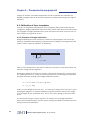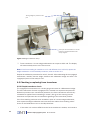
1
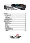
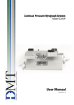
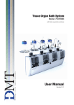
Muscle Strip Myograph System
Model 800MS
User Manual
Version 2.2
Muscle strip myograph system Model 800MS
Muscle Strip Myograph System - Model 800MS
User manual
Trademarks
PowerLab® and LabChart® are registered trademarks of ADInstruments Pty Ltd. The names of specific
recording units, such as PowerLab 4/25, are trademarks of ADInstruments Pty Ltd.
Pentium is a registered trademark of the Intel Corporation. Windows, Windows 95, Windows 98,
Windows ME, Windows NT, Windows 2000 and Windows XP are registered trademarks of Microsoft
Corporation. All other trademarks are the properties of their respective owners.
DMT reserves the right to alter specifications as required.
This document was, as far as possible, accurate at the time of printing. Changes may have been made to
the software and hardware it describes since then. New information may be supplied separately.
This documentation is provided with the DMT muscle strip myograph system –
Model 800MS – v. 2.2
Document Number: 800MS – UG2.2A
No part of this document may be reproduced by any means
without the prior written permission of DMT.
Copyright © 2008 DMT A/S
DMT A/S
Skejbyparken 152
DK-8200 Aarhus N
Denmark
Tel.: +45 87 41 11 00
Fax: +45 87 41 11 01
www.dmt.dk
[email protected]
[email protected]
DMT - Asia
Everwin Gardens
Rm 502, Block B
521 Wanping Nan Lu
Shanghai 200030
China
Tel: + 86 (0) 21 64869685
Fax: + 86 (0) 21 64280591
www.dmt-asia.com
[email protected]
[email protected]
DMT-USA, Inc.
1201 Peachtree Street
400 Colony Square, Suite 200-630
Atlanta, GA 30361
USA
Tel.: +1 770 612 8014
Fax: +1 678 302 7013
www.dmt-usa.com
[email protected]
[email protected]
User manual 800MS
Trademarks
Introduction
The 800MS muscle strip myograph system represents the first state-of-the-art
four-channel myograph system for muscle strips of up to 15 mm in length. DMT
developed this system for simultaneous measurement of up to four isolated muscle
preparations, mounted as strips between clamp supports. Several types of mounting
supports exist depending on the user’s preferences, and customized mounting
supports can be made upon request. Moreover, because of the rectangular chamber,
the “muscle unit” can also be used for the study of larger strips of various other
organs including larger pieces of smooth muscle.
Stimulation electrodes are available built into the chamber cover (optional) and can
be used to activate the muscle via field stimulation from a pulse/train stimulator,
such as the DMT CS200.
The muscle bath unit is constructed of aluminium, while the centrally located
rectangular chamber is stainless steel for easy cleaning. The segment clamp supports
are positioned in the chamber with one side attached to the force transducer and the
other side to a micrometer. The micrometers permit the accurate setting of muscle
length and the sensitive force transducers measure the resulting isometric muscle
tension. Each unit has individually controlled gas inflow and suction. The system is
automatically heated to a given set temperature above ambient.
Following mounting and equilibration, the optimal length-tension relationship for
the muscle can be determined and the muscle length set to this value with the
micrometer. The length of the muscle is kept constant during the experiment, i.e. the
muscle is examined under isometric conditions. Compounds are added directly to the
chamber and muscle tension is monitored for chronotropic or intropic effects of the
compound. The bath fluid can be sampled for metabolic factors.
This myograph is well-suited for investigations on muscle reactivity and multiple
units can be arranged conveniently side-by-side. The force readings are available for
external data acquisition via either calibrated (filtered) or uncalibrated (unfiltered)
analog outputs or in digital format via a serial connection. Furthermore, due to
its four-channel design the 800MS is ideal for work requiring high-throughput
screening (HTS), such as drug testing or in experiments where comparison of muscle
preparations from control and treated or gene-modified animals is required.
Muscle Strip Myograph System Model 800MS
Safety
The muscle strip myograph system has been designed for use only in teaching
and research applications. It is not intended for clinical or critical life-care use and
should never be used for these purposes: nor for the prevention, diagnosis, curing,
treatment, or alleviation of disease, injury, or handicap.
• Do not open the unit: the internal electronics pose a risk of electric shock.
• Do not use this apparatus near water.
• To reduce the risk of fire or electric shock, do not expose this apparatus
to rain or moisture. Objects filled with liquids should not be placed on the
apparatus.
• Do not block any ventilation openings. Install in accordance with the
manufacturer's instructions.
• Do not install near any heat sources such as radiators, heat registers, stoves,
or other apparatus that produce heat.
• Only use attachments and accessories specified by the manufacturer.
• Unplug this apparatus during lightning storms or when unused for long
periods of time.
• This apparatus must be grounded.
• Use a three-wire grounding-type cord similar to the one supplied with the
product.
• Do not defeat the safety purpose of the polarized or grounding-type plug.
A polarized plug has two flat blades, one being wider than the other. A
grounding type plug has two blades and a third (round) grounding pin. The
wide blade or the third prong is provided for your safety. If the provided plug
does not fit into your outlet, consult an electrician for replacement of the
obsolete outlet.
• Be advised that different operating voltages require the use of different types
of line cord and attachment plugs. Check the voltage in your area and use the
correct type. See the table below:
Voltage
Line plug according to standard
110–125 V
UL817 and CSA C22.2 No. 42.
220–230 V
CEE 7 page VII, SR section 107-2-D1/IEC 83, page C4.
240 V
BS 1363 of 1984. Specification for 13A fused plugs and switched and unswitched socket outlets.
Protect the power cord from being walked on or pinched: particularly at power plugs
and the point where they connect to the apparatus.
Refer all servicing to qualified service personnel. Servicing is required when the
apparatus has been damaged in any way; such as, the power-supply cord or plug
is damaged, liquid has spilled onto or objects have fallen into the apparatus, the
apparatus has been exposed to rain or moisture, does not operate normally, or has
been dropped.
User manual 800MS
Safety
EMC / EMI
This equipment has been tested and found to comply with the limits for a Class
B Digital device, pursuant to part 15 of the FCC rules. These limits are designed
to provide reasonable protection against harmful interference in residential
installations. This equipment generates, uses and can radiate radio frequency
energy and, if not installed and used in accordance with the instructions, may cause
harmful interference to radio communications. However, there is no guarantee that
interference will not occur in a particular installation. If this equipment does cause
harmful interference to radio or television reception (which can be determined by
monitoring the interference while turning the equipment off and on), the user is
encouraged to correct the interference by one or more of the following measures:
• Reorient or relocate the receiving antenna.
• Increase the separation between the equipment and receiver.
• Connect the equipment into an outlet on a circuit different to that which the
receiver is connected to.
• Consult the dealer or an experienced radio/TV technician for help.
Approvals
Complies with the EMC standards:
EMC 89/336/EEC: EN 61326-2-6:2005
EN 61000-3-2.
Certified with the safety standards:
Directive 2006/95/EC: EN 61010-1:2001
EN 61010-1/Corr.1:2003
EN 61010-1/Corr.1:2003
EN 61010-2-101:2003
Muscle strip myograph system Model 800MS
Certificate of Conformity
DMT A/S, Skejbyparken 152, 8200 Aarhus N., Denmark,
hereby declares its responsibility that the following product:
Muscle Strip Myograph System
Model 800MS version 2.2
is covered by this certificate and marked with CE-label conforms
with the following standards:
EN 61010-1:2001
EN61010-1/Corr.1:2003
EN 61010-1/Corr.1:2003
Safety requirements for electrical equipment for
measurement, control, and laboratory use Part 1: General requirements.
EN 61010-2-101:2003
Safety requirements for electrical equipment for
measurement, control and laboratory use - Part 2101: Particular requirements for in vitro diagnostic
(IVD) medical equipment.
EN 61326-2-6:2005
Electrical equipment for measurement, control and
laboratory use - EMC
requirements - Part 2-6: Particular requirements - In
vitro diagnostic (IVD) medical equipment.
With reference to regulations in the following directives: 2006/95/EC, 89/336/EEC
User manual 800MS
Certificate of Conformity
Contents
Trademarks ���������������������������������������������������������������������������������������������������������3
Introduction���������������������������������������������������������������������������������������������������������4
Safety�������������������������������������������������������������������������������������������������������������������5
EMC / EMI�����������������������������������������������������������������������������������������������������������6
Approvals�������������������������������������������������������������������������������������������������������������6
Certificate of Conformity������������������������������������������������������������������������������������7
About this manual����������������������������������������������������������������������������������������������9
Unpacking the myograph system��������������������������������������������������������������������10
Chapter 1 - System overview�������������������������������������������������������������������������� 11
1.1 Myo-Interface front panel������������������������������������������������������������������������������������������ 11
1.2 Myo-Interface rear panel������������������������������������������������������������������������������������������� 11
1.3 Muscle Strip Myograph Unit������������������������������������������������������������������������������������� 12
Chapter 2 - Setting up������������������������������������������������������������������������������������� 13
2.1 The complete muscle strip 800MS myograph system�������������������������������������������� 13
2.2 Setting up step-by-step��������������������������������������������������������������������������������������������� 13
2.3 The first weight calibration���������������������������������������������������������������������������������������� 15
Chapter 3 - The Myo-Interface�������������������������������������������������������������������������16
3.1 Turning on the Myo-Interface������������������������������������������������������������������������������������ 16
3.2.0 Main menus and submenus������������������������������������������������������������������������������������������������16
Chapter 4 - The muscle strip myograph unit������������������������������������������������� 20
4.1 Calibration of force transducer��������������������������������������������������������������������������������� 20
4.1.1 Principles of weight calibration��������������������������������������������������������������������������������������������20
4.1.2 Weight calibration procedure�����������������������������������������������������������������������������������������������21
4.2 Checking or replacing force transducer������������������������������������������������������������������� 22
4.2.1 Simple transducer check������������������������������������������������������������������������������������������������������22
4.2.2 Force transducer replacement���������������������������������������������������������������������������������������������23
4.3 Myograph maintenance�������������������������������������������������������������������������������������������� 23
4.3.1 Myograph chamber pipes�����������������������������������������������������������������������������������������������������23
4.3.2 Force transducer�������������������������������������������������������������������������������������������������������������������24
4.3.3 Screw thread�������������������������������������������������������������������������������������������������������������������������24
4.3.4 Myograph cleaning����������������������������������������������������������������������������������������������������������������25
4.3.5 Mounting a muscle strip on the 800MS������������������������������������������������������������������������������27
Appendix 1 - Terms of warranty���������������������������������������������������������������������� 28
Appendix 2 - Service check����������������������������������������������������������������������������� 29
Appendix 3 - Shipping instructions���������������������������������������������������������������� 30
Appendix 4 - Myograph accessories and spare parts �����������������������������������31
Appendix 5 - Fuse replacement���������������������������������������������������������������������� 33
Appendix 6 - System specifications��������������������������������������������������������������� 34
Muscle strip myograph system Model 800MS
About this Manual
This manual contains a complete list of procedures describing how to install, maintain
and get started using the muscle strip myograph system – Model 800MS – version
2.2.
Chapter 1 provides an overview of the construction and basic features of the Myo-Interface and the muscle strip myograph unit.
Chapter 2 describes step-by-step how to set-up a complete muscle strip myograph
system – Model 800MS including accessories.
Chapter 3 is a complete manual to the Myo-Interface. The chapter describes in detail
the construction of the menu system and how to use all the features of the muscle
Strip Myograph System - Model 800MS.
Chapter 4 contains procedures describing general as well as daily maintenance of
the myograph unit; e.g. adjustment of supports, weight calibration of the force transducer and cleaning instructions.
Appendices contain various additional information about myograph service, shipping
instructions, system accessories and spare parts, system specifications and fuse
replacement.
User manual 800MS
Contents
Unpacking the myograph system
Please take a few minutes to carefully inspect your new muscle strip myograph
system for damage, which may have occurred during handling and shipping. If you
suspect any kind of damage, please contact DMT immediately and the matter will be
pursued soon as possible. If the packing material appears damaged, please retain it
until a possible claim has been settled.
We recommend that you store the packing material for any possible future transport
of the muscle strip myograph system. In case of transport and the original packing
material is unavailable, please contact DMT Sales Department for advice and packing
instructions.
After unpacking your new system, please use the following list to check that the
system is complete:
• 1 interface unit
• 4 chamber units with mounted clamp supports
• 4 chamber covers
• 1 external temperature probe
• 1 power cord*
• 1 calibration kit (including bridge, balance and 2 g weight)
• 1 tube of high vacuum grease
• 1 tube of grease for screw thread
• 2 Allen keys
• 1 small screwdriver
• 1 user manual
* The shape of the AC plug varies by country; be sure that the plug has the right
shape for your location
10
Muscle strip myograph system Model 800MS
Chapter 1 - System overview
1.1 Myo-Interface front panel
Power indicator
Myo-Interface display
Suction/gas pipe
Valve keys
Function keys
1.2 Myo-Interface rear panel
4 Recorder outputs (uncalibrated)
Regulator
ON/OFF switch
Gas
Suction
4 Recorder outputs (calibrated)
Power connector
RS 485 Port for serial connection to PC
RS 282 Port for serial connection to PC
Temperature probe
User manual 800MS
Chapter 1
11
1.3 Muscle strip myograph unit
Connection to Myo-Interface
Micrometer
Myograph clamp support connected to micrometer
Myograph clamp support connected
to force transducer
12
Muscle strip myograph system Model 800MS
Force transducer pin
Chapter 2 — Setting up
2.1 The complete muscle strip 800MS myograph system
Myo-Interface front panel
Power supply
PowerLab data acquisition system
(optional)
DMT CS200 Pulse/Train Stimulator
(optional)
PC USB connection
Myo-Interface rear panel
PC data acquisition and analysis
software (optional)
Power supply
Connection to oxygen supply
BNC cables
Vacuum pump
(optional)
RS serial connection
Suction bottle (optional)
Optional
Figure 2.1 The complete muscle strip myograph system - Model 800MS
2.2 Setting up step-by-step
The chapter contains a complete step-by-step description of how to set up a complete
Myograph 800MS System as illustrated in fig. 2.1
1.Myo-Interface – PC connection:
Data acquisition is possible either by connecting the Myo-Interface directly to a PC
or through a PowerLab data acquisition and analysis system (optional).
l. Direct PC connection:
Connect the Myo-Interface to one of the COM-ports on the PC using a serial cable.
ll.PowerLab (optional):
Connect the Myo-Interface to the PowerLab unit using BNC cables. Connect
Rec 1 on the Myo-Interface to Input 1 on the PowerLab. Rec 2 to Input 2 etc.
Connect the PowerLab unit to one of the USB-ports on the PC using the USB
cable delivered with the PowerLab system. Follow the “DMT Quick Guide” instructions delivered with the PowerLab system to install the PowerLab driver
and Chart software on the PC.
User manual 800MS
Chapter 2
13
Note: there are two types of analog recorder outputs on the rear panel of the 800MS
system. The top four provide a direct raw voltage signal from the transducer (uncalibrated
and unfiltered). The bottom four BNC connections provide a calibrated signal with a
fixed 1 V output, where the voltage output corresponds to the mN setting in the MyoInterface Recorder menu (described in Chapter 3).
2.Gas supply:
The gas supply tubes must be connected in order to have the solution aerated
(fig. 2.2). Connect the main gas supply on the back of the interface. Each myograph unit has a small diameter silicone tube which should be connected to the
gas tube from the rear panel of the interface (it has a stainless steel tube). The
needle valves are used to regulate the level of bubbling to each chamber. Each
needle valve has a lock device attached.
Note: To ensure longevity, the needle valves should be turned regularly (completely in and out a few times) and greased to prevent them from becoming stiff (use
the linear grease provided with the system).
3.Suction connection:
The system has an inbuilt aeration manifold with separate valves that allow each
chamber to be drained individually. After connecting your suction source to the
interface, the appropriate chamber will be drained by pressing the associated
numeric button.
Note: When draining the chambers using the automatic suction function, continuing to press the button for an additional 3-5 seconds after the chamber appears
to be empty will ensure no residual solution is retained in the tubing and valves.
4. Chamber covers
The chamber covers are used to keep the temperature and other conditions
(gas tension, pH) of the solution surrounding the mounted segment as accurate
as possible (fig. 2.3) Optional stimulation electrodes are available built into the
chamber cover and can be used to activate the muscle via field stimulation (fig.
2.4).
Oxygen supply
Suction connection
Figure 2.2 Oxygen supply and suction connection
14
Muscle strip myograph system Model 800MS
Figure 2.3 Chamber cover
Figure 2.4. Chamber cover with
in-built electrodes (optional)
2.3 The first weight calibration
Prior to the shipment of the Muscle Strip Myograph 800MS it has gone through two
days of continuous testing including a final weight calibration. However in order to
ensure that the myograph is working at highest performance, DMT recommends that
a new weight calibration is performed before starting to use the myograph system.
The weight calibration procedure is described in detail in Chapter 4.
User manual 800MS
Chapter 2
15
Chapter 3 — The Myo-Interface
3.1 Turning on the Myo-Interface
When the 800MS Myo-Interface is switched on, the start-up
message depicted to the right is shown.
Muscle Strip Myograph System
Model 800MS
Version 2.2
After a few seconds, during which the system autocalibrates the
A/D converters, the force menu will be displayed automatically.
3.2 Main menus and submenus
General navigation
The various menus are selected, the data changed and values
entered with the F1, F2 and the arrow buttons. The F1 and F2
button functions differ according to the current menu while the
arrow buttons typically have the following functions:
←- → Increase and decrease the data in the active line,
respectively
↑ ↓
Scroll up and down in the menus.
The active line in the menu is indicated by a > symbol displayed
in the left side of the display.
Force menu
The force menu provides an on-line reading of the force values in
millinewtons (mN).
Removing and replacing a chamber unit
When a chamber unit is unplugged from the Myo-Interface, the
force display does not show a force value. An example display is
depicted to the right, where myograph unit 1 is unplugged.
To replace the unit, firstly press the arrow displayed in the active
line. The display now changes to “Now mount myo No.1”. Put the
chamber unit in place on the interface (always place chamber
unit one at No. 1 on the interface, unit two on No.2, and so forth)
and plug the chamber cable into the corresponding input on the
interface’s rear panel.
If the unit is not plugged into the interface within ~10 seconds,
then the arrow key should be pressed again (the interface will
display the previous message). Once the unit is connected, the
active line will again display a force reading.
Force 1:
Force 2 :
Force 3 :
Force 4 :
0.04 mN
-1.03 mN
1.87 mN
-0.23 mN
PUSH ↑ BEFORE MOUNT
Force 2 :
-1.03 mN
Force 3 :
1.87 mN
Force 4 :
-0.23 mN
NOW MOUNT MYO NO.1
Force 2:
-1.03mN
Force 3:
1.87mN
Force 4:
-0.23mN
Zero menu
This menu is used to zero the output of the transducers. The F1
button changes which transducer is active in the list (Slct. stands
for select). Pressing the F2 button will zero the selected transducer (indicated by >).
16
Muscle strip myograph system Model 800MS
> Zero 1
Zero 2 Zero 3 Zero 4
F1:Slct.
F2:Zero
After selecting F2, the selected transducer will be zeroed and
the display will automatically return to the force menu. Re-enter the zero menu using the arrow down button (↓), choose the
next transducer with the F1 button and zero with F2. Repeat
this procedure until all transducers have been zeroed.
To simultaneously zero all channels, enter the zero menu and
press the right arrow (→) and F2 at same time.
Note: there should be no force applied to the transducers
when zeroing.
Heat menu
In this menu, the heating and temperature settings are controlled. The F1 button turns the heat ON and F2 switches it
OFF. The temperature the myograph heats to (“Set. temp.”)
is decreased with the ← button and increased with →. “Act.
Temp.” is the actual temperature measured by the external
temperature probe when connected to the interface. If there is
no probe connected, Act. Temp. OFF will be displayed.
Note: Whenever the system is turned on (by the power switch
on the rear panel) the heating is automatically off until turned
on by the user. When the heating is on the set temperature will
be reached in ~20 minutes.
Act. temp.:
Set. temp.:
Heat is
ON
36.9 ºC
37.0 ºC
F1= ON
F2=OFF
Recorder menu (calibrated outputs)
The 800MS Myo-Interface has four 1 V full-scale analog outputs, which provide the force signal in volts for connection to
an external data acquisition system. By default the interface is
set at 20 mN, where 20 mN corresponds to 1 V. As the force
value will vary, according to the maximum response from the
preparation used, the maximum force value can be changed by
firstly making the channel of interest active and then increasing or decreasing the value using the ← or → buttons. Irrespective of which maximum force value is entered, the analog
output is fixed to 1 V at max.
> Force 1 OUT:
Force 2 OUT:
Force 3 OUT:
Force 4 OUT:
20 mN
20 mN
20 mN
20 mN
> Calibrate 1:
Calibrate 2:
Calibrate 3:
Calibrate 4:
F1:
Slct.
F2:
Cal.
Calibration menu
The calibration menu permits calibration of the transducers
using the calibration kit provided with the 610M system. The
F1 button changes which transducer is active in the list (Slct.
stands for select). Pressing the F2 button will begin the calibration process for the force transducer selected (indicated by >).
Calibration of the transducers is described in full in Chapter 4.
Setup menu
The Setup menu provides access to submenus, which are
used to change the gain setting, serial port connection and
link if multiple systems are connected. To enter the desired
submenu, use the ← or → buttons and when the appropriate
number is shown, the submenu is activated by pressing F2.
Whenever any changes have been made, one must return to
the Setup menu (using ↑) for the changes to take effect.
Set-up:
User manual 800MS
0
Chapter 3
17
Valve delay submenu
The valve delay submenu is found under Setup submenu #3.
By default the valve delay is set to 1 second: the available
delay range is 1 to 99 seconds. The valve delay is the time the
valve is open once you have released the valve button on the
front panel. The delay time is changed using the ← and →
buttons.
Valve delay: 1 sec
Force range submenu
The force range submenu is found in Setup submenu #7. By
default the force range is set at ±200 mN. The available ranges are: ±200, ±400, ±800 and ±1600 mN. The force range is
changed using the ← and → buttons.
Force Range: 200mN
Serial port submenu
For digital storage of data, the interface has an integrated
RS232 port and two RS485 serial ports. The RS232 serial port
is used when a single system is connected to a computer and
the RS485 serial ports are used for multiple connections (up to
four systems – linked together allowing 16 force channels and
four temperature readings).
By default the system is set to use RS232, and functions for
the serial settings are found in Setup submenu #10. To switch
between the two outputs use the ← and → buttons.
Using the enclosed serial cable with the mounted adapter, the
9-pin plug is connected to the RS232 plug of the interface and
the 25-pin plug connected to the serial port (COM port) on the
computer.
RS232 Serial Port
This serial communication protocol must be used when only
one system is connected to one PC.
RS485 Serial Port
This serial communication protocol must be used when multiple systems are linked together. In order to use this feature
an external or internal signal converter that is half duplex and
toggles RTS signals are required. The converter (if external)
must be placed between the computer and the first myograph.
Note: For further information, please contact DMT.
> Serial port: RS232
> Serial port: RS485
Linking multiple systems
Connect a serial cable to the computer and to the signal converter. Connect a second serial cable to the other end of the
signal converter and the other end of the cable to the RS485
plug on the myograph system that will be #1.
Connect a serial cable to the other RS485 plug on the interface. Other end of cable must be connected to system #2.
Repeat this if 3 or 4 systems are linked together.
Important:
When using the serial connection, the systems must always be
linked as follows: system 1 to 2, 2 to 3, and 3 to 4.
18
Muscle strip myograph system Model 800MS
>Serial port: RS485
Myograph no.: 1
When all systems are linked together in the above order enter submenu 10. Press ←
to change serial port to RS485. Use F1 to move the active line marker (>) down and
select the system number equivalent to the way in which the serial cables have been
connected. Exit the serial port menu by pressing ↑.
User manual 800MS
Chapter 3
19
Chapter 4 — The muscle strip myograph unit
Chapter 4 contains a complete explanation of how to calibrate and maintain the
800MS myograph units to ensure the equipment is always performing to the highest
standard.
4.1 Calibration of force transducer
As a part of the general maintenance of the myograph, DMT recommends that the
myograph is weight calibrated at least once every month. DMT also recommends that
the myograph is weight calibrated every time the system has been moved or has not
been used for a long period of time.
4.1.1 Principles of weight calibration
Weight calibrating the force transducer is based on simple physics: the net torque
acting on a balance when applying a certain amount of weight. The magnitude of the
torque τ about a point of rotation P is defined by:
r
F
P
θ
τ = r · F · sinθ
where r is the distance from the point of rotation to the point on the object where the
force F is acting with the angle of θ.
Applying the weight on the pan arm creates a net torque acting at the “center of gravity” resulting in a force FT acting on the force transducer. The following two equations
describe the forces working in the weight calibration system:
1. τ = rPA · FW · sinθ1 = rPA · (mweigt · g) · sinθ1
2. τ = rTA · FT · sinθ2
where rPA is the length of the “pan arm”. FW is the force acting on the “pan arm” when
applying the weight. FW is equal acceleration of gravity times the mass of the weight.
rTA is the length of the “transducer arm” and FT is the force acting on the force transducer.
The net torque acting at “center of gravity” is constant for the weight calibration
setup, which makes equation 1 and 2 equal, making it possible to calculate the force
acting on the force transducer:
20
Muscle strip myograph system Model 800MS
rTA · FT · sinθ2 = rPA · (mweigt · g) · sinθ1
FT = rPA · (mweigt · g) · sinθ1
rTA · sinθ2
As the length of the “pan arm” is 2 cm, the length of the “transducer arm” is 4 cm,
the weight is 2 g, both angles are 900 and the acceleration of gravity is 9.81 ms-2, the
force acting on the force transducer is:
FT = 2 cm · (2 g · 9.81 ms-2) · sin90
4 cm · sin90
FT = 9.81 gram · m · s-2
As 1 N is equal 1 kg · m · s-2, FW is equal to:
FT = 9.81 mN
4.1.2 Weight calibration procedure
The section contains a complete step-by-step description of how to weight calibrate
the force transducer.
1. Place the units on the interface, plug in the cables, and fill the chambers with
double distilled water.
2. Place the calibration bridge, balance and weight on the first myograph unit allowing it to be pre-warmed together with the myograph unit (it is important that the
calibration kit is warm). Turn on the heating in the Heat menu of the Myo-Interface. The system will typically reach the target set temperature (by default, 370C)
after ~20 minutes.
3. Place the calibration bridge, balance and weight on myograph unit 1 as illustrated in fig. 4.1. Make sure that the tip of the transducer arm on the balance is
positioned protruding behind the clamp support. Carefully move the calibration
bridge until the tip of the transducer arm is hanging free, which means it does
not touch the side of the chamber or the support (inset enlargement in fig. 4.1).
Note: The weight should not be placed on the balance yet.
4. Go to the Calibration menu on the Myo-Interface. Ensure Calibrate 1 is active
(the > symbol is displayed to the left; use the F1 button to scroll through the list).
When the relative force reading in the display is stable, press F2 to proceed with
calibration of force transducer 1
5. Carefully place the 2 g weight on the pan (as pointed out in fig. 4.1). The force
applied on the force transducer should mimic the stretch created by the contraction of the mounted preparation. Wait until the relative force reading is stable.
Press F2 to finish the calibration.
User manual 800MS
Chapter 4
21
The 2 g weight is placed on this
pan
The tip of the transducer arm on the
balance is positioned behind the
clamp support.
Figure 4.1 Weight calibration setup
7. Force transducer 1 is now weight calibrated to an output at 9.81 mN. The display
will automatically return to the Force menu.
Note: If the force reading is unstable or >0.1 mN different from 9.81 mN, repeat the
weight calibration. If the instability continues, refer to section 4.2.
Repeat the calibration procedure for units 2, 3 and 4. After calibrating all the myograph
transducers, carefully remove weight, balance and calibration bridge and store. The
myograph system is now ready for use.
4.2 Checking or replacing force transducer
4.2.1 Simple transducer check
The myograph force transducer is a strain gauge connected in a Wheatstone bridge.
The force transducer for each myograph unit is located in a separate compartment.
While this provides some mechanical protection, the force transducers are still very
vulnerable to applied forces exceeding 1 newton (100 g) or fluid running into the
transducer compartment due to insufficient greasing of the transducer pinhole.
If the force reading continues to be unstable in spite of a recent weight calibration,
then repeat the weight calibration and note down the relative force reading values
shown in the Calibration menu on the Myo-Interface:
• If the value is 0 or above 6500 then the force transducer is broken, and needs to
22
Muscle strip myograph system Model 800MS
be changed.
• If the value is between 1—499 or 3001—6250 then contact DMT for further
instructions.
Important:
If at any time the message “OFF” is displayed in the Force menu on the Myo-Interface, this indicates that the force transducer is broken and must be replaced. In this
instance, or in case of other problems related to the force transducer, please contact
DMT for further instruction and advice.
4.2.2 Force transducer replacement
If the force transducer is broken and needs to be changed, please follow this step-bystep replacement procedure carefully:
1. Disconnect the myograph unit from the Myo-Interface (grey cable).
2. Remove the myograph clamp support connected to the transducer pin.
3. Turn the myograph unit upside down and remove the bottom plate by loosening the two screws (A+B) as illustrated in fig. 4.2. Carefully disconnect the force
transducer plug and remove the old transducer*.
*Note how the plug is connected to the old force transducer to prevent incorrect
connection of the new force transducer.
4. Remove any remaining grease from the transducer pin left inside of the transducer compartment of the myograph unit. Also clean the hole leading from the
transducer compartment to the myograph chamber.
5. Plug the replacement transducer in.
6. Replace the bottom plate and tighten the two Allen screws.
7. Place some high vacuum grease (supplied with the system) around the transducer pin in the myograph chamber. Make sure that the hole is completely sealed so
that absolutely no buffer solution is able to enter the transducer compartment
and damage the force transducer.
A
B
Figure 4.2 The Allen screws to be loosened when replacing the transducer
Important:
The new force transducer must be weight calibrated prior to running an experiment.
4.3 Myograph maintenance
The Muscle Strip Myograph System Model 800MS is a delicate and sophisticated
piece of research equipment, DMT recommend that the following sections are read
carefully and that the instructions are followed at all times.
4.3.1 Myograph chamber pipes
To prevent the pipes from being blocked by buffer salt deposits after an experiment,
remove the chamber cover from the myograph and turn on the vacuum pump and
User manual 800MS
Chapter 4
23
vacuum valve for about 10 seconds (continuously press the valve button down). Turn
off the vacuum pump and then the oxygen supply. Remove any buffer remaining on
the outside of the pipes with absorbent paper.
4.3.2 Force transducer
The force transducer is the most delicate and fragile component of the myograph
system and it should therefore be handled with the utmost care.
One of the jaws in each myograph is connected to the transducer pin. The transducer
pin is attached to the myograph mounting supports and is located outside of the
chamber (fig. 4.3). Despite there being no direct contact to the salt solution in the
chamber, there is a risk for evaporating solution to deposit calcium in the pinhole. The
hole running into the transducer house the hole is therefore filled with high vacuum
grease.
Figure 4.3 Transducer pin holes
to be sealed up with high vacuum
grease
As a part of daily maintenance it is very important to inspect the greasing of the transducer hole before starting any experiment. Insufficient greasing permits salts and
fluid to enter, thereby causing damage and malfunction of the force transducer.
4.3.3 Screw thread
Check the screw thread for grease at least once a week. In case of insufficient lubrication, grease the thread with the original enclosed grease for screw thread at the
places marked by the arrow in fig. 4.4.
Figure 4.4 Greasing point
for the screw thread
24
Muscle strip myograph system Model 800MS
4.3.4 Myograph cleaning
DMT strongly recommends that the myograph chamber and surroundings should be
cleaned after each experiment.
After an experiment use the following procedure to clean the myograph chamber and
supports:
1. Fill the myograph chamber to the edge with an 8% acetic acid solution and allow
it to work for a few minutes to dissolve calcium deposits and other salt build-up.
Use a swab stick to mechanically clean all chamber surfaces.
2. Remove the acetic acid and wash the myograph chamber and supports several
times with double distilled water.
3. If any kind of hydrophobic reagent have been used, which might be difficult to
remove using step 1) and 2) then try incubating the chamber and supports with
96% ethanol or a weak detergent solution.
4. To remove more resistant or toxic chemicals incubate the myograph chamber
and supports with 1M HCl for up to 1 hour. In exceptional cases incubate the
chamber and supports with an up to 3M HNO3 solution for about 15 minutes.
5. Wash the myograph chamber and supports several times with double distilled
water.
Important Notes:
• Be very careful using step 3) and 4) repeatedly times as strong reagents may
cause extreme damage to the myograph unit.
• After cleaning, ALWAYS check that the greasing around the transducer pin is sufficient to keep the buffer solution away from the transducer compartment.
In cases of red or brown discolorations appearing on the chamber sides or on the
supports, the following cleaning procedure will work in most cases:
1. Incubate the myograph chamber and supports for 30 minutes with 20 μL of a
2mM T-1210 Tetrakis- (2-pyridylmethyl)-ethylenediamine solution dissolved in
double distilled water.
2. Use a swab-stick to mechanically clean all the affected surfaces during the last
15 minutes of the incubation period.
3. Wash the myograph chamber and supports several times with double distilled
water.
4. Incubate the myograph chamber with 96% ethanol for 10 minutes while continuing the mechanical cleaning with a swab-stick.
5. Remove the ethanol solution and wash a few times with double distilled water.
Incubate the myograph chamber and supports with an 8% acetic acid solution
for 10 minutes and continue the mechanical cleaning with a swab-stick.
6. Wash the myograph chamber and supports several times with double distilled
water.
User manual 800MS
Chapter 4
25
Important Notes:
• In exceptional cases, to make sure that all surfaces are cleaned, it may be necessary to remove the supports so that they are cleaned separately from the myograph chamber.
26
Muscle strip myograph system Model 800MS
4.3.5 Mounting a muscle strip on the 800MS
1. Starting position.
2. Loosen the screws on the
clamp support.
3. Turn the upper part of the
support to expose the lower
part.
4. Place the muscle strip onto
the lower part of the clamp
support.
5. Turn the top part back into
position so that the muscle
strip is clamped between the
upper and lower parts.
6. Secure the screws.
User manual 800MS
Chapter 4
27
Appendix 1 — Terms of warranty
Warranty
DMT A/S warrants to the original user that myograph systems manufactured by DMT
A/S will be free from defects in materials and workmanship for a period of three years
after the date of delivery. DMT A/S will repair or replace any defective part, subject to
the conditions, limitations and exclusions.
Exclusions
Force and pressure transducers, separately or part of myograph systems manufactured by DMT A/S, are disclaimed from any warranty.
Limitations
This warranty shall not apply to equipment subjected to accidental damage, improper
use, alteration, or deterioration.
Warranty on third-party products will be as determined by their respective manufacturer.
DMT A/S shall not be liable for consequential, incidental, special, or other direct or
indirect damages resulting from economic loss or property damage sustained by you
or any end user from the use of the products sold or services rendered hereunder.
Warranty returns
A “Return Material Authorisation” (RMA) number is required for all returns. This
number should be clearly indicated on all returned myograph systems.
Products damaged due to improper or inadequate packaging when returned for RMA
purposes are not granted warranty coverage.
28
Muscle strip myograph system Model 800MS
Appendix 2 — Service check
A myograph working at optimal performance is extremely important for success when
studying isometric force recordings. To make sure that our customers always are dealing with first class myographs, DMT offers a Myograph Service Check at a very favora����������
ble price.
The Myograph Service check includes a complete separation for inspection of all
mechanical and electronic parts. The myograph is then reassembled, adjusted and
finally all electronic and mechanical parts are tested.
Please note that the service does not include replacement of transducers or any
other required spare parts. Please contact DMT for information about prices.
User manual 800MS
Appendix 2
29
Appendix 3 — Shipping instructions
If the myograph system needs to be sending back for service or repair, please read
the following shipping instructions very carefully.
Before you start packing the myograph system, please remember that you are dealing
with very delicate equipment and therefore care must be taken. DMT recommends
that each part of the myograph system be wrapped individually (i.e. with bubble wrap)
and placed together in a large box (preferable the box you once received the myograph system in). Place the wrapped items in the middle of the box and fill out the
surroundings with chips of expanded polystyrene.
Important:
Before closing the box, make sure that no enclosed items can be shaken around as
transport by road or air from time to time can be quite roughly.
Address the box to:
DMT A/S
Skejbyparken 152
DK-8200 Aarhus N
Denmark
Make sure that all four sides of the box are marked “fragile” or similar. Make an indication on the top of the box that it contains goods returned for repair/service.
Customers outside the EC must further enclose a pro forma invoice stating that the
box contains goods being returned for repair or service.
If arranging transportation through a courier, please keep in mind the high value of
the myograph system and that a standard insurance provided by the courier in most
cases is insufficient to cover damage or loss of the myograph system. In most cases
an additional insurance coverage is needed.
30
Muscle strip myograph system Model 800MS
Appendix 4 — Myograph accessories and spare parts
This appendix contains a complete register of equipment needed to set-up a Muscle
Strip Myograph System. In addition the chapter contains a list of special 800MS myograph accessories and spare parts.
Besides the main focus on development and manufacturing, DMT has specialised
in offering our customers first class laboratory equipment needed for a Muscle Strip
Myograph setup at very competitive prices. Please contact the DMT Sales Department for further product information and prices.
A4.1 General myograph equipment
This section contains a complete checklist of laboratory equipment needed when setting up a Muscle Strip Myograph system:
• Dissection stereo microscope (Including ocular micrometer and stage micrometer) DMT recommends the Zeiss Stemi 2000 Stereo Microscope
• Mounting forceps DMT Item # DF-3000
DMT recommends Dumont Medical No 5 tip (0.10 mm x 0.06 mm).
• Dissection scissors DMT Item # DS-1000
DMT recommends Geuder G-19745 8 cm straight trabeculum.
• Pipettes
DMT recommends CappAero μpipettes.
• Light source
DMT recommends Schott Cold Light Source, either Model KL 200 or Model KL
1500 LCD.
• Water bath including heater
DMT recommends Julabo 5 L open bath circulator with plexiglass bath tank.
• Glass bottle 2 L
• Vacuum pump
DMT recommends a membrane vacuum pump with a volume of at least 6 L/min.
• Dissection petri dish DMT Item # PD-2000
DMT recommends a ~9 cm glass Petri dish coated with a 5mm Sylgard polymer
layer
A4.2 Myograph 800MS system accessories
This section contains a list of special accessories available for the Muscle Strip Myograph System – Model 800MS:
• ADI PowerLab data acquisition system
Including Chart data acquisition and analysis software.
User manual 800MS
Appendix 4
31
• pH-meter
Including pH electrode and pH-meter.
• Standard PC system DMT Item # 80150
• DMT CS-200 (4 Channel) Current Stimulators
Combined pulse and train generator.
• Vertical hooks (another possibility as supports)
A4.3 Myograph 800MS system spare parts
This section contains a complete list of standard spare parts available for the myograph 800MS. For parts not listed in this appendix or for special parts, which may
need to be custom made, please contact DMT for further information.
• Force transducer DMT Item # FT-61780
• High vacuum grease and grease for screw thread DMT Item # HVG-1000
• Calibration kit DMT Item # CK-6127800
• 40 mm funnels DMT Item # F-2000
32
Muscle strip myograph system Model 800MS
Appendix 5 — Fuse replacement
The main fuse of the myograph system is placed inside the power inlet on the MyoInterface.
When a fuse blows and needs to be changed, it is imperative that the replacement
fuse is equal to the one blown.
The 610M system uses: T1.6A / 250 V, 6.3 x 32 mm
DMT recommends that both fuses in the fuse block are changed at the same time, as
it can be difficult to determine which fuse is blown.
To replace the fuses:
1. Use a small screwdriver to open the voltage selector block.
2.
Remove the red fuse block.
3.
Remove the existing fuses.
4.
Insert the new fuses.
5. Replace the fuse block back into the voltage selector block
Note: ensure that the correct voltage for your country is displayed.
Voltage selector
block
Red Fuse Block
Fuse
Fuse
User manual 800MS
Appendix 5
33
Appendix 6 — System specifications
Muscle strips:
Chamber:
Chamber material:
Chamber volume:
Chamber suction:
Chamber gassing:
Chamber cover:
Force range:
Force resolution: Weight calibration:
Heating:
Temp. range:
Temp. resolution:
Temp. probe:
Output reading:
Recorder output:
Recorder output:
Standard:
Serial output:
Voltage:
>3 mm - 15 mm
Four individual chambers
Acid-resistant stainless steel
Max. 4 mL
Manual or automatic
Individually controlled per chamber by needle valves
With electrodes (optional)
User selectable at ±200, ±400, ±800 and ±1600 mN
0.01 mN
Semi automatic
Built-in
Ambient temp. to 50° C
0.1°C
External
Force (mN)
1.0 V full scale (calibrated)
Direct transducer output (uncalibrated)
+/- 0.26 mV/mN (± 10%)
RS232 / RS485 (2 Hz)
100 to 240 VAC (auto) 50/60 Hz
Muscle unit:
The rectangle chamber allows a maximum segment length of 15 mm and can also be
used for study of various organs.
Internal chamber dimensions:
Length: 45 mm
Depth: 13.5 mm
Width: 11 mm
Supports:
The clamp supports have a width of 3 mm. Another option is vertical hook supports,
where the muscle strip ends are mounted with suture wire.
34
Muscle strip myograph system Model 800MS
DMT A/S
Skejbyparken 152
DK-8200 Aarhus N
Denmark
Tel.: +45 87 41 11 00
Fax: +45 87 41 11 01
www.dmt.dk
[email protected]
[email protected]
DMT - Asia
Everwin Gardens
Rm 502, Block B
521 Wanping Nan Lu
Shanghai 200030
China
Tel: + 86 (0) 21 64869685
Fax: + 86 (0) 21 64280591
www.dmt-asia.com
[email protected]
[email protected]
DMT-USA, Inc.
1201 Peachtree Street
400 Colony Square, Suite 200-630
Atlanta, GA 30361
USA
Tel.: +1 770 612 8014
Fax: +1 678 302 7013
www.dmt-usa.com
[email protected]
[email protected]