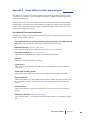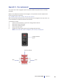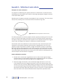
1
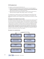
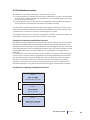
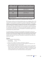
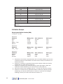
Tissue Bath System Model 700MO User Manual Version 2.2 Tissue bath system Model 700MO Tissue Bath System - Model 700MO User manual Trademarks PowerLab® and LabChart® are registered trademarks of ADInstruments Pty Ltd. The names of specific recording units, such as PowerLab 4/25, are trademarks of ADInstruments Pty Ltd. Pentium is a registered trademark of the Intel Corporation. Windows, Windows 95, Windows 98, Windows ME, Windows NT, Windows 2000 and Windows XP are registered trademarks of Microsoft Corporation. All other trademarks are the properties of their respective owner DMT reserves the right to alter specifications as required. This document was, as far as possible, accurate at the time of printing. Changes may have been made to the software and hardware it describes since then. New information may be supplied separately. This documentation is provided with the DMT Tissue bath system – Model 700MO – Version 2.2 Document Number: 700MO – UG2.2A No part of this document may be reproduced by any means without the prior written permission of DMT. Copyright © 2008 DMT A/S DMT A/S Skejbyparken 152 DK-8200 Aarhus N Denmark Tel.: +45 87 41 11 00 Fax: +45 87 41 11 01 www.dmt.dk [email protected] [email protected] DMT - Asia Everwin Gardens Rm 502, Block B 521 Wanping Nan Lu Shanghai 200030 China Tel: + 86 (0) 21 64869685 Fax: + 86 (0) 21 64280591 www.dmt-asia.com [email protected] [email protected] DMT-USA, Inc. 1201 Peachtree Street 400 Colony Square, Suite 200-630 Atlanta, GA 30361 USA Tel.: +1 770 612 8014 Fax: +1 678 302 7013 www.dmt-usa.com [email protected] [email protected] User manual 700MO Trademarks Introduction Until the mid-1970s most of the details about the mechanical, morphological and pharmacological properties of vascular smooth muscle was obtained from studies on relatively large vessels. At that time, rat tail arteries were the smallest vessels to be investigated in detail due to limitations in the available in vitro techniques. For example, studies measuring the contraction force were routinely performed with only one of the mounting wires secured. Furthermore, relatively large wires (100-200 μm) were used, which precluded the use of small vessels, and the vessel segment had to be directly manipulated with the dissecting equipment causing inevitable mechanical trauma. Investigations of smaller vessels were therefore limited to in vivo perfusion experiments and histological examinations. In 1976, Professors Mulvany and Halpern described for the first time a new technique that made it possible to investigate highly-isometric responses from vessels with internal diameters as small as 100 μm. The mounting procedure was refined twofold: both ends of each mounting wire were secured under tension without any direct manipulation of the vessel segment. Segments of small vessels could now be atraumatically mounted as ring preparations in a myograph for recording of highly isometric force measurements. During the late 1970s some improvements were made to the myograph and in 1981 a new dual myograph that allowed simultaneous testing of two vessels was introduced. In parallel, the technique became widely acknowledged resulting in a growing interest in the myograph systems. In 1986, the growing demand resulted in the foundation of the private company J.P. Trading with the purpose of making the myograph systems commercially available worldwide. At the same time J.P. Trading initiated a comprehensive improvement programme for the existing myograph systems as well as a development programme of new myograph systems in close cooperation with Professor M. J. Mulvany and the University of Aarhus. During the late 1980s and through the 1990s several improvements were applied to the myograph systems, such as a new mechanical design, a more robust transducer and new electronic systems. In addition, new systems were introduced, like the Automatic Dual Myograph 510A, the Dual Myograph 410A, the Multi Myograph 610M and the Confocal Myograph 120CW. In 2000 J.P. Trading changed its company structure and became known as DMT. Today DMT is one of the world’s leading designers and manufacturers of wire myographs, pressure myographs, culture myographs and organ/tissue baths. Driven by our global customer base, our number one goal is to develop and manufacture first class research equipment within the fields of physiology and pharmacology. Tissue bath system Model 700MO Safety The Tissue bath system has been designed for use only in teaching and research applications. It is not intended for clinical or critical life-care use and should never be used for these purposes: nor for the prevention, diagnosis, curing, treatment, or alleviation of disease, injury, or handicap. • Do not open the unit: the internal electronics pose a risk of electric shock. • Do not use this apparatus near water. • To reduce the risk of fire or electric shock, do not expose this apparatus to rain or moisture. Objects filled with liquids should not be placed on the apparatus. • Do not block any ventilation openings. Install in accordance with the manufacturer’s instructions. • Do not install near any heat sources such as radiators, heat registers, stoves, or other apparatus that produce heat. • Only use attachments and accessories specified by the manufacturer. • Unplug this apparatus during lightning storms or when unused for long periods of time. • This apparatus must be grounded. • Use a three-wire grounding-type cord similar to the one supplied with the product. • Do not defeat the safety purpose of the polarized or grounding-type plug. A polarized plug has two flat blades, one being wider than the other. A grounding type plug has two blades and a third (round) grounding pin. The wide blade or the third prong is provided for your safety. If the provided plug does not fit into your outlet, consult an electrician for replacement of the obsolete outlet. • Be advised that different operating voltages require the use of different types of line cord and attachment plugs. Check the voltage in your area and use the correct type. See the table below: Voltage Line plug according to standard 110–125 V UL817 and CSA C22.2 No. 42. 220–230 V CEE 7 page VII, SR section 107-2-D1/IEC 83, page C4. 240 V BS 1363 of 1984. Specification for 13A fused plugs and switched and unswitched socket outlets. Protect the power cord from being walked on or pinched: particularly at power plugs and the point where they connect to the apparatus. Refer all servicing to qualified service personnel. Servicing is required when the apparatus has been damaged in any way; such as, the power-supply cord or plug is damaged, liquid has spilled onto or objects have fallen into the apparatus, the apparatus has been exposed to rain or moisture, does not operate normally, or has been dropped. User manual 700MO Safety EMC / EMI This equipment has been tested and found to comply with the limits for a Class B Digital device, pursuant to part 15 of the FCC rules. These limits are designed to provide reasonable protection against harmful interference in residential installations. This equipment generates, uses and can radiate radio frequency energy and, if not installed and used in accordance with the instructions, may cause harmful interference to radio communications. However, there is no guarantee that interference will not occur in a particular installation. If this equipment does cause harmful interference to radio or television reception (which can be determined by monitoring the interference while turning the equipment off and on), the user is encouraged to correct the interference by one or more of the following measures: • Reorient or relocate the receiving antenna. • Increase the separation between the equipment and receiver. • Connect the equipment into an outlet on a circuit different to that which the receiver is connected to. • Consult the dealer or an experienced radio/TV technician for help. Approvals Complies with the EMC standards: EMC 89/336/EEC: EN 61326-2-6:2005 EN 61000-3-2. Certified with the safety standards: Directive 2006/95/EC: EN 61010-1:2001 EN 61010-1/Corr.1:2003 EN 61010-1/Corr.1:2003 EN 61010-2-101:2003 Tissue bath system Model 700MO Certificate of Conformity DMT A/S, Skejbyparken 152, 8200 Aarhus N., Denmark, hereby declares its responsibility that the following product: Tissue Bath System Model 700MO Version 2.2 is covered by this certificate and marked with CE-label conforms with the following standards: EN 61010-1:2001 EN61010-1/Corr.1:2003 EN 61010-1/Corr.1:2003 Safety requirements for electrical equipment for measurement, control, and laboratory use Part 1: General requirements. EN 61010-2-101:2003 Safety requirements for electrical equipment for measurement, control and laboratory use - Part 2101: Particular requirements for in vitro diagnostic (IVD) medical equipment. EN 61326-2-6:2005 Electrical equipment for measurement, control and laboratory use - EMC requirements - Part 2-6: Particular requirements - In vitro diagnostic (IVD) medical equipment. With reference to regulations in the following directives: 2006/95/EC, 89/336/EEC User manual 700MO Certificate of Conformity Contents Trademarks ���������������������������������������������������������������������������������������������������������3 Introduction���������������������������������������������������������������������������������������������������������4 Safety�������������������������������������������������������������������������������������������������������������������5 EMC / EMI�����������������������������������������������������������������������������������������������������������6 Approvals�������������������������������������������������������������������������������������������������������������6 Certificate of Conformity������������������������������������������������������������������������������������7 About this manual����������������������������������������������������������������������������������������������9 Unpacking the Tissue bath system�����������������������������������������������������������������10 Chapter 1 — System overview������������������������������������������������������������������������� 11 1.1 Myo-Interface front panel������������������������������������������������������������������������������������������ 11 1.2 Myo-Interface rear panel������������������������������������������������������������������������������������������� 11 1.3 Tissue bath unit��������������������������������������������������������������������������������������������������������� 12 Chapter 2 — Setting up������������������������������������������������������������������������������������ 13 2.1 The complete Tissue bath system���������������������������������������������������������������������������� 13 2.2 Setting up step-by-step��������������������������������������������������������������������������������������������� 13 2.3 The first weight calibration���������������������������������������������������������������������������������������� 14 Chapter 3 — The Myo-Interface����������������������������������������������������������������������� 15 3.1 Turning on the Myo-Interface������������������������������������������������������������������������������������ 15 3.2 Main menus and submenus������������������������������������������������������������������������������������� 15 Chapter 4 — The Tissue bath unit������������������������������������������������������������������� 19 4.1 Change and adjustment of mounting supports������������������������������������������������������ 19 4.2 Force transducer calibration������������������������������������������������������������������������������������� 20 4.3 Checking force transducer���������������������������������������������������������������������������������������� 22 4.4 Force transducer replacement��������������������������������������������������������������������������������� 23 4.5 Myograph maintenance�������������������������������������������������������������������������������������������� 24 Chapter 5 — Getting started����������������������������������������������������������������������������27 5.1 Normalization������������������������������������������������������������������������������������������������������������� 27 5.2 Standard start����������������������������������������������������������������������������������������������������������� 28 5.3 Endothelium Function����������������������������������������������������������������������������������������������� 29 5.4 In Vitro Experiment 1: Noradrenaline contractile response����������������������������������� 30 5.5 In Vitro Experiment 2: Acetylcholine relaxation curve��������������������������������������������� 30 Appendix 1 — Terms of warranty��������������������������������������������������������������������� 34 Appendix 2 — Service check��������������������������������������������������������������������������� 35 Appendix 3 — Shipping instructions��������������������������������������������������������������� 36 Appendix 4 — Tissue bath accessories and spare parts��������������������������������37 A4.1 General Tissue bath equipment����������������������������������������������������������������������������� 37 A4.2 Tissue bath 700MO accessories���������������������������������������������������������������������������� 38 A4.3 Tissue bath 700MO spare parts���������������������������������������������������������������������������� 38 Appendix 5 — Fuse replacement�������������������������������������������������������������������� 39 Appendix 6 — Calibration of ocular reticule�������������������������������������������������� 40 Appendix 7 — How to read a millimetre micrometer������������������������������������ 43 Appendix 8 — Normalization theory��������������������������������������������������������������� 43 Appendix 9 — System specifications ������������������������������������������������������������� 45 Tissue Bath System Model 700MO About this manual This manual contains a complete list of procedures describing how to install, maintain and get started using the Tissue bath system – Model 700MO – version 2.2. Chapter 1 provides an overview of the construction and basic features of the Myo-Interface and the Tissue bath unit. Chapter 2 describes step-by-step how to set-up a complete 700MO Tissue bath system including accessories. Chapter 3 is a complete manual to the Myo-Interface. The chapter describes in detail the construction of the menu system and how to use all the features of the Tissue bath system. Chapter 4 contains procedures describing general as well as daily maintenance of the Tissue bath unit; e.g. adjustment of supports, weight calibration of the force transducer and cleaning instructions. Chapter 5 describes how to get started using the Tissue bath system. This includes a discussion about normalization and a few example pharmacological experiments (which are suitable for studies with large blood vessels). Appendices contain additional information about normalization theory, ocular calibration, service, shipping instructions, system specifications, equipment lists (accessories and spare parts), and fuse replacement. User manual 700MO About this manual Unpacking the Tissue bath system Please take a few minutes to carefully inspect your new Tissue Bath System for damage, which may have occurred during handling and shipping. If you suspect any kind of damage, please contact DMT immediately and the matter will be pursued soon as possible. If the packing material appears damaged, please retain it until a possible claim has been settled. We recommend that you store the packing material for any possible future transport of the Tissue bath system. In case of transport and the original packing material is unavailable, please contact DMT Sales Department for advice and packing instructions. After unpacking your new Tissue bath system, please use the following list to check that the system is complete: • 1 interface unit • 4 chamber units with mounted pin supports (200 µm) • 4 chamber covers • 1 external temperature probe • 1 power cord* • 1 calibration kit (including “bridge”, “balance” and 2 gram weight) • 4 plastic funnels • 1 tube of high vacuum grease • 1 tube of grease for linear slides • 2 Allen keys • 1 small screwdriver • 1 DMT Tissue bath 700MO system User manual • 1 manual by Professor M. J. Mulvany - “Procedures for Investigation of small vessels using small vessel myograph” * The shape of the AC plug varies by country; be sure that the plug has the right shape for your location 10 Tissue bath system Model 700MO Chapter 1 — System overview 1.1 Myo-Interface front panel Power indicator Myo-Interface display Valve keys Function keys 1.2 Myo-Interface rear panel Gas regulator (needle valve) Gas input Suction 4 Recorder outputs ON/OFF switch Power connector RS 485 port for serial connection to PC RS 282 port for serial connection to PC Temperature probe User manual 700MO Chapter 1 11 1.3 Tissue bath unit Micropositioner Myograph pin support connected to micrometer Myograph pin support connected to transducer Force transducer pin 12 Tissue bath system Model 700MO Chapter 2 — Setting up 2.1 The complete Tissue bath system Myo-Interface front panel Power supply PowerLab data acquisition system (optional) DMT CS200 Pulse/Train Stimulator (optional) PC USB connection Myo-Interface rear panel PC data acquisition and analysis software (optional) Power supply Connection to oxygen supply BNC Cables Vacuum pump (optional) RS serial connection Suction bottle (optional) Figure 2.1 The complete Tissue bath system - Model 700MO. The dotted lines represent optional connections to the system. 2.2 Setting up step-by-step The chapter contains a complete step-by-step description of how to set up a complete Tissue Bath system as illustrated in fig. 2.1 1.Myo-Interface – PC connection: Data acquisition is possible either by connecting the Myo-Interface directly to a PC or through a PowerLab data acquisition and analysis system (optional). l. Direct PC connection: Connect the Myo-Interface to one of the COM-ports on the PC using a serial cable. (Cable not included.) ll.PowerLab (optional): Follow the “DMT Quick guide” instructions delivered with the PowerLab system to install the PowerLab driver and LabChart software on the computer. Follow the instructions provided in the DMT QuickStart guide “Data acquisition - Tissue bath system 700MO and PowerLab/LabChart”. User Manual 700MO Chapter 2 13 2.Gas supply: The gas supply into the chamber is a plastic tube which is conveniently attached to the stainless steel suction pipe. The tube must be placed in the chamber in order to have the solution aerated (described below). Connect the main gas supply to the gas input tube on the rear panel of the interface. The needle valves are used to regulate the level of bubbling to each chamber. Each needle valve has a lock device attached. Note: To ensure longevity, the needle valves should be turned regularly (fully out and in a few times) and greased to prevent them from becoming stiff or fixed (use the linear grease provided with the system). 3.Suction connection: The system has an inbuilt aeration manifold with separate valves that allow each chamber to be drained individually. After connecting your suction source to the interface, the appropriate chamber will be drained by pressing the associated numeric button. The suction pipes are inserted into the chambers by gently pulling the pipe up, turning it 90o counter clockwise and releasing it into the chamber (fig. 2.2). Note: When draining the chambers using the automatic suction function, continuing to press the button for an additional 3-5 seconds after the chamber appears to be empty will ensure no “leftovers” from the previous solution are retained in the tubing and valves. Gas Suction Funnel For drug application Temperature probe Figure 2.2 Suction connection Figure 2.3 Chamber cover 4. Chamber covers: The chamber covers are used to keep the temperature and other conditions (gas tension, pH) of the solution surrounding the mounted segment as accurate as possible. There are holes in the covers, which serve multiple functions (fig. 2.3) and slots for the mounting supports and suction/gas tubes. 2.3 The first weight calibration Prior to the shipment of the Tissue bath 700MO system, it has gone through two days of continuous testing including a final weight calibration. However in order to ensure that the myograph is working at highest performance, DMT recommends that a new weight calibration is performed before starting to use the myograph system. The weight calibration procedure is described in detail in Chapter 4. 14 Tissue bath system Model 700MO Chapter 3 — The Myo-Interface 3.1 Turning on the Myo-Interface When the Tissue Bath 700MO is switched on, the start-up message depicted to the right is shown. Tissue Bath System Model 700MO Version 2.2 After a few seconds, during which the system autocalibrates the A/D converters, pressing one of the arrow buttons will display the force menu. 3.2 Main menus and submenus General navigation The various menus are selected, the data changed and values entered with the F1, F2 and the arrow buttons. The F1 and F2 button functions differ according to the current menu while the arrow buttons typically have the following functions: ←- → Increase and decrease the data in the active line, respectively ↑ ↓ Scroll up and down in the menus. At the top line of a menu use ↑ to change to the previous main menu The active line in the menu is indicated by a > symbol displayed in the left side of the display Force menu The force menu provides an online reading of the force values in millinewtons (mN). Removing and replacing a chamber unit When a chamber unit is unplugged from the Myo-Interface, the force display does not show a force value. An example display is depicted to the right, where myograph unit 1 is unplugged. To replace the unit, firstly press the arrow displayed in the active line. The display now changes to “Now mount myo No.1”. Put the chamber unit in place on the interface (Note: Always place chamber unit one at No. 1 on the interface, unit two on No.2, and so forth) and plug the chamber cable into the corresponding input on the interface’s rear panel. If the unit is not plugged into the interface within ~10 seconds, then the arrow key should be pressed again (the interface will display the previous message). Once the unit is connected, the active line will again display a force reading. Force 1: Force 2 : Force 3 : Force 4 : 0.04 mN -1.03 mN 1.87 mN -0.23 mN PUSH ↑ BEFORE MOUNT Force 2 : -1.03 mN Force 3 : 1.87 mN Force 4 : -0.23 mN NOW MOUNT MYO NO.1 Force 2: -1.03mN Force 3: 1.87mN Force 4: -0.23mN Zero menu This menu is used to zero the output of the transducers. The F1 button changes which transducer is active in the list (Slct. stands for select). Pressing the F2 button will zero the selected transducer (indicated by >). After selecting F2, the selected transducer will be zeroed and > Zero 1 Zero 2 Zero 3 Zero 4 User manual 700MO F1:Slct. F2:Zero Chapter 3 15 the display will automatically return to the force menu. Re-enter the zero menu using the arrow down button (↓), choose the next transducer with the F1 button and zero with F2. Repeat this procedure until all transducers have been zeroed. To simultaneously zero all channels, enter the zero menu and press the right arrow (→) and F2 at same time. Note: there should be no force applied to the transducers when zeroing. Heat menu In this menu, the heating and temperature settings are controlled. The F1 button turns the heat ON and F2 switches it OFF. The temperature the myograph heats to (“Set. temp.”) is decreased with the ← button and increased with →. “Act. Temp.” is the actual temperature measured by the external temperature probe when connected to the interface. If there is no probe connected, Act. Temp. OFF will be displayed. Note: Whenever the system is turned on (by the power switch on the rear panel) the heating is automatically off until turned on by the user. When the heating is on the set temperature will be reached in ~20 minutes. Recorder menu The 610M Myo-Interface has four 1 V full-scale analog outputs, which provide the force signal in volts for connection to an external data acquisition system. By default the interface is set at 20 mN, where 20 mN corresponds to 1 V. As the force value will vary, according to the maximum response from the preparation used, the maximum force value can be changed by firstly making the channel of interest active and then increasing or decreasing the value using the ← or → buttons. Irrespective of which maximum force value is entered, the analog output is fixed to 1 V at max. Calibration menu The calibration menu permits calibration of the transducers using the calibration kit provided with the 610M system. The F1 button changes which transducer is active in the list (Slct. stands for select). Pressing the F2 button will begin the calibration process for the force transducer selected (indicated by >). Calibration of the transducers is described in full in Chapter x. Setup menu The Setup menu provides access to submenus, which are used to change the gain setting, serial port connection and link if multiple systems are connected. To enter the desired submenu, use the ← or → buttons and when the appropriate number is shown, the submenu is activated by pressing F2. Whenever any changes have been made, one must return to the Setup menu (using ↑) for the changes to take effect. 16 Tissue bath system Model 700MO Act. temp.: Set. temp.: Heat is ON 36.9 ºC 37.0 ºC F1= ON F2=OFF > Force 1 OUT: Force 2 OUT: Force 3 OUT: Force 4 OUT: 20 mN 20 mN 20 mN 20 mN > Calibrate 1: Calibrate 2: Calibrate 3: Calibrate 4: F1: Slct. F2: Cal. Set-up: 0 Valve delay submenu The valve delay submenu is found under Setup submenu #3. By default the valve delay is set to 1 second: the available delay range is 1 to 99 seconds. The valve delay is the time the valve is open once you have released the valve button on the front panel. The delay time is changed using the ← and → buttons. Force range submenu The Force Range submenu is found in Setup submenu #7. By default the force range is set at ±200 mN. The available ranges are: ±200, ±400, ±800 and ±1600 mN. The force range is changed using the ← and → buttons. Valve delay: 1 sec Force Range: 200mN Serial port submenu For digital storage of data, the interface has an integrated RS232 port and two RS485 serial ports. The RS232 serial port is used when a single system is connected to a computer and the RS485 serial ports are used for multiple connections (up to four systems – linked together allowing 16 force channels and four temperature readings). By default the system is set to use RS232, and functions for the serial settings are found in Setup submenu #10. To switch between the two outputs use the ← and → buttons. Using the enclosed serial cable with the mounted adapter, the 9-pin plug is connected to the RS232 plug of the interface and the 25-pin plug connected to the serial port (COM port) on the computer. RS232 Serial port This serial communication protocol must be used when only one system is connected to one PC. RS485 Serial port This serial communication protocol must be used when multiple systems are linked together. In order to use this feature an external or internal signal converter that is half duplex and toggles RTS signals are required. The converter (if external) must be placed between the computer and the first myograph. Note: For further information, please contact DMT. Linking multiple systems Connect a serial cable to the computer and to the signal converter. Connect a second serial cable to the other end of the signal converter and the other end of the cable to the RS485 plug on the myograph system that will be #1. Connect a serial cable to the other RS485 plug on the interface. Other end of cable must be connected to system #2. Repeat this if 3 or 4 systems are linked together. > Serial port: RS232 > Serial port: RS485 >Serial port: RS485 Myograph no.: 1 Important: When using the serial connection, the systems must always be linked as follows: system 1 to 2, 2 to 3, and 3 to 4. User manual 700MO Chapter 3 17 When all systems are linked together in the above order enter submenu 10. Press ← to change serial port to RS485. Use F1 to move the active line marker (>) down and select the system number equivalent to the way in which the serial cables have been connected. Exit the serial port menu by pressing ↑. 18 Tissue bath system Model 700MO Chapter 4 — The Tissue bath unit This chapter contains a complete explanation of how to adjust, calibrate and maintain the Tissue bath 700MO units to ensure the equipment performs to the highest standard. 4.1 Change and adjustment of mounting supports The chamber units can accommodate mounting supports of various sizes. As the mounting supports are readily changed it is easy to perform experiments with different vessel sizes. The mounted supports will require adjustment with time due to continuous use of the myograph system and repeated greasing of the transducer pinhole. Note: The transducers are fragile and sensitive to mechanical strain. Be very cautious not to put strain on the transducer when changing or adjusting the mounting supports. Changing supports (fig. 4.1) 1. Loosen screw (A) to align support vertically 2.Loosen screw (B + C) to move support back or forward 3.Loosen the screws on the side of the supports to adjust as necessary horizontal Figure 4.1 Changing supports A B C Changing the pins (fig. 4.2): 4.Rewind the micrometer positioner all the way back 5.Loosen the screw (A) close to the transducer and carefully pull the head with the “female part” 6.Loosen the screw (B) on the micrometer side and perform the same procedure A B Figure 4.2 Changing pins User manual 700MO Chapter 4 19 4.2 Force transducer calibration As a part of the general maintenance of the myograph, DMT recommends that the myograph is weight calibrated at least once every month. DMT also recommends that the myograph is weight calibrated every time the system has been moved or has not been used for a long period of time. Principles of weight calibration Weight calibrating the force transducer is based on simple physics: the net torque acting on a balance when applying a certain amount of weight. The magnitude of the torque τ about a point of rotation P is defined by: r F P θ τ = r · F · sinθ Arm Pan (PA) Transducer Arm (TA) where r is the distance from the point of rotation to the point on the object where the force F is acting with the angle of θ. Applying the physics to the weight calibration setup is illustrated in fig. 4.3. rPA FW τ rTA FT Figure 4.3. Thereotical principle of the weight calibration Applying the weight on the pan arm creates a net torque acting at the “center of gravity” resulting in a force FT acting on the force transducer. The following two equations describe the forces working in the weight calibration system: 1. τ = rPA · FW · sinθ1 = rPA · (mweigt · g) · sinθ1 2. τ = rTA · FT · sinθ2 where rPA is the length of the “pan arm”. FW is the force acting on the “pan arm” when applying the weight. FW is equal acceleration of gravity times the mass of the weight. rTA is the length of the “transducer arm” and FT is the force acting on the force transducer. 20 Tissue bath system Model 700MO The net torque acting at “center of gravity” is constant for the weight calibration setup, which makes equation 1 and 2 equal, making it possible to calculate the force acting on the force transducer: rTA · FT · sinθ2 = rPA · (mweigt · g) · sinθ1 FT = rPA · (mweigt · g) · sinθ1 rTA · sinθ2 As the length of the “pan arm” is 2 cm, the length of the “transducer arm” is 4 cm, the weight is 2 g, both angles are 900 and the acceleration of gravity is 9.81 ms-2, the force acting on the force transducer is: FT = 2cm · (2 g · 9.81 ms-2) · sin90 4 cm · sin90 FT = 9.81 gram · m · s-2 As 1 N is equal 1 kg · m · s-2, FW is equal to: FT = 9.81 mN Weight calibration procedure 1. Move the pins apart in the myograph chambers. Mount a wire on the transducer side of the myograph jaws in all chambers*. Place the units on the interface, plug in the cables, and fill the chambers with double distilled water *This is not required if the mounting support pins are used instead of the jaws. 2. Turn on the heating in the Heat main menu of the Myo-Interface. The system will typically reach the target set temperature (by default, 370C) after ~20 minutes. 3. Place the calibration bridge, balance and weight on myograph unit 1 as illustrated in fig. 4.6. It is important that the calibration kit is pre-warmed together with the myograph unit. Make sure that the tip of the “transducer arm” on the balance is positioned protruding behind the pin illustrated in Figure 4.4. Carefully move the calibration bridge until the tip of the “transducer arm” is placed freely, which means it does not touch the pin. Figure 4.4 Weight calibration setup User manual 700MO Chapter 4 21 4. Once the system has warmed up to the set temperature (check by placing the temperature probe into the chamber), go to the Calibration menu on the MyoInterface. In the Calibration menu, ensure Calibrate 1 is active (the > symbol is displayed to the left; use the F1 button to scroll through the list) and press F2 to initiate calibration of force transducer 1. 5. Ensure that the tip of the transducer arm is not touching the mounting support pin. It is imperative that the force transducer is not subjected to any force at this stage. When the relative force reading in the display is stable, press F2 to proceed with the calibration. 6. Carefully place the 2 g weight on the pan as illustrated in fig. 4.5. The force applied on the force transducer as the tip of the arm pushes against the mounted wire (or support pin) should mimic the stretch created by the contraction of a mounted ring preparation. Wait until the relative force reading is stable, then press F2 to finish the calibration. Figure 4.5 Illustration of how to fit the balance between the wire and the gap in the support Force transducer 1 is now weight calibrated to an output of 9.81 mN. The display will automatically return to the Force menu. Note: If the force reading is unstable or >0.1 mN different from 9.81 mN, repeat the weight calibration. If the instability continues, refer to section 4.3. 6. Carefully remove the weight, balance and calibration bridge from myograph unit 1 and move to myograph unit 2. Repeat steps 4–6 for force transducer 2, 3 and 4. 4.3 Checking force transducer The myograph force transducer is a strain gauge connected in a Wheatstone bridge. The force transducer for each myograph unit is located in a separate compartment (transducer house, see Chapter 1.3). While this provides some mechanical protection, the force transducers are still very vulnerable to applied forces exceeding 1 newton (100 gram) or fluid running into the transducer compartment due to insufficient greasing of the transducer pinhole. If the force reading continues to be unstable in spite of a recent weight calibration, then repeat the weight calibration and note down the relative force reading values shown in the Calibration menu on the Myo-Interface: 22 Tissue bath system Model 700MO • If the value is 0 or above 6500 then the force transducer is broken, and needs to be changed. • If the value is between 1—499 or 3001—6250 then contact DMT for further instructions. Important: If at any time the message “OFF” is displayed in the Force menu on the Myo-Interface, this indicates that the force transducer is broken and must be replaced. In this instance, or in case of other problems related to the force transducer, please contact DMT for further instruction and advice. 4.4 Force transducer replacement If the force transducer is broken and needs to be changed, please follow this step-bystep replacement procedure carefully: 1. Disconnect the myograph unit from the Myo-Interface (grey cable). 2. Turn the myograph unit upside down and remove the bottom plate by loosening the two screws (A+B) as illustrated in fig. 4.6. Carefully disconnect the force transducer plug and remove the old transducer*. *Note how the plug is connected to the old force transducer to prevent incorrect connection of the new force transducer. B A Figure 4.6 The two screws holding the transducer house in place 3. Remove any remaining grease from the transducer pin left inside of the transducer compartment of the myograph unit. Also clean the hole leading from the transducer compartment to the myograph chamber. 4. Replace the bottom plate and tighten the two Allen screws. 5. Place some high vacuum grease (supplied with the system) around the transducer pin in the myograph chamber. Make sure that the hole is completely sealed so that absolutely no buffer solution is able to enter the transducer compartment and damage the force transducer. Important: The new force transducer must be weight calibrated prior to running an experiment. User manual 700MO Chapter 4 23 4.5 Myograph maintenance The Tissue Bath 700MO is a delicate and sophisticated piece of research equipment, DMT recommend that the following sections are read carefully and that the instructions are followed at all times. Myograph chamber pipes To prevent the pipes from being blocked by buffer salt deposits after an experiment, remove the chamber cover from the myograph and turn on the vacuum pump and vacuum valve for about 10 seconds (continuously press the valve button down). Turn off the vacuum pump and then the oxygen supply. Remove any buffer remaining on the outside of the pipes with absorbant paper. Force transducer The force transducer is the most delicate and fragile component of the myograph system and it should therefore be handled with the utmost care. One of the jaws in each myograph is connected to the transducer pin. The transducer pin is attached to the myograph mounting supports and is located outside of the chamber (as illustrated in fig. 4.7). Despite there being no direct contact to the salt solution in the chamber, there is a risk for evaporating solution to deposit calcium in the pinhole. The hole running into the transducer house the hole is therefore filled with high vacuum grease. Figure 4.7 Transducer pin hole to be sealed up with high vacuum grease (red arrows indicate points where grease should be checked and replaced) As a part of daily maintenance it is very important to inspect the greasing of the transducer hole before starting any experiment. Insufficient greasing permits salts and fluid to enter, thereby causing damage and malfunction of the force transducer. Important: • DMT recommends with frequent use of the myograph that the high vacuum grease sealing up the transducer hole is checked, and if necessary replaced, once a week. • DMT takes no responsibilities for the use of any other kinds of high vacuum grease than the one available from DMT. • DMT takes no responsibilities for any kind of damage applied to the force transducer. Linear slides Check the linear slides (under the black covers) for grease at least once a week. In case of insufficient lubrication grease the slides with the “Grease for Linear Slides” enclosed with the myograph. Apply the linear slide grease at the places marked by the arrows in fig 4.8. 24 Tissue bath system Model 700MO Figure 4.8 Greasing points on the linear slides Myograph cleaning DMT strongly recommends that the myograph chamber and surroundings are cleaned after each experiment. At the end of the experiment, use the following procedure to clean the myograph chamber and supports: 1. Fill the myograph chamber to the edge with an 8% acetic acid solution and allow it to work for a few minutes to dissolve calcium deposits and other salt build-up. Use a swab stick to mechanically clean all chamber surfaces. 2. Remove the acetic acid and wash the myograph chamber and supports several times with double distilled water. 3. If any kind of hydrophobic reagent have been used, which might be difficult to remove using step 1) and 2) then try incubating the chamber and supports with 96% ethanol or a weak detergent solution. 4. To remove more resistant or toxic chemicals incubate the myograph chamber and supports with 1 M HCl for up to 1 hour. In exceptional cases incubate the chamber and supports with an up to 3 M HNO3 solution for about 15 minutes. 5. Wash the myograph chamber and supports several times with double distilled water. Important Notes: • Be very careful using step 3) and 4) repeatedly, as strong reagents may damage the myograph unit. • After cleaning, ALWAYS check that the greasing around the transducer pin is sufficient to keep the buffer solution away from the transducer compartment. In cases of red or brown discolorations appearing on the chamber sides or on the supports, the following cleaning procedure will work in most cases: 1. Incubate the myograph chamber and supports for 30 minutes with 20 μl of a 2 mM T-1210 Tetrakis- (2-pyridylmethyl)-ethylenediamine solution dissolved in double distilled water. 2. Use a cotton swab-stick to mechanically clean all the affected surfaces during the last 15 minutes of the incubation period. 3. Wash the myograph chamber and supports several times with double distilled water. 4. Incubate the myograph chamber with 96% ethanol for 10 minutes while continuUser manual 700MO Chapter 4 25 ing the mechanical cleaning with a swab-stick. 5. Remove the ethanol solution and wash a few times with double distilled water. Incubate the myograph chamber and supports with an 8% acetic acid solution for 10 minutes and continue the mechanical cleaning with a swab-stick. 6. Wash the myograph chamber and supports several times with double distilled water. Important: • In exceptional cases it may be necessary to demount the supports and clean them and the myograph chamber seperately to ensure that all surfaces are cleaned. 26 Tissue bath system Model 700MO Chapter 5 — Getting started 5.1 Normalization The importance of normalising the preparation is three-fold: 1. Experiments with elastic preparations like vessels can only have meaning if they are performed under conditions where the size is clearly defined. 2. Clearly defined conditions are required in pharmacological experiments as the sensitivity of preparations to agonists and antagonists is dependent on the amount of stretch. 3. The active response of a preparation is dependent on the extent of stretch, which makes it important to set the preparation to an internal circumference giving maximal response. The aim of the normalization procedure is to stretch the segment to a so-called normalized internal circumference (IC1): defined as a set fraction of the internal circumference (IC100) that a fully relaxed segment would have at a specified transmural pressure. For small rat arteries the target transmural pressure is typically 100 mmHg = 13.3 kPa. For other ring preparations (such as vas deferens or ileum), this procedure may not be necessary. In which case, stretching the vessel to a pre-defined level of force may be sufficient. Principles of the normalization procedure In practice the normalization is performed by distending the segment stepwise and measuring sets of micrometer and force readings (fig 5.1, step 1-4). These data are converted into values of internal circumference (μm) and wall tension T (mN/mm) respectively. Plotting wall tension against internal circumference reveals an exponential curve and by applying the isobar curve corresponding to 100 mmHg, IC100 is calculated from the point of intersection using the Laplace relation (fig. 5.2). IC1 is calculated from IC100 by multiplying a factor giving an internal circumference at which the active force production as well as the sensitivity to agonists of the segment is maximal. For rat mesenteric arteries the factor is 0.9 but both this factor as well as the transmural pressure has to be optimised for each particular segment.The normalized internal diameter is calculated by dividing IC1 with . Appendix 8 , contains a complete description of the mathematical rationale and calculations of the normalization procedure. Figure 5.1 Illustration of the stepwise normalization procedure Figure 5.2 Illustration of the exponential curve fitting and determination of IC100 User manual 700MO Chapter 5 27 5.2 Standard start The purpose of performing a standard start is to: 1. Re-activate the mechanical and functional properties of the vessel segment. 2. Check that responses to different types of stimuli are normal in appearance and thereby ensuring that the functionality of the vessel segment has not been damaged during the dissection or mounting procedures. 3. Ensure that the tension development gives an effective active pressure that is above the chosen accepted value (usually 13.3 kPa = 100 mmHg). The standard start is performed after the vessel segment has been heated, equilibrated and normalized. The present procedure is suitable for rat mesenteric arteries. Another procedure may be needed for other animal species and tissue or vessel types. Principles of the standard start procedure The standard start procedure consists of a series of five stimuli and washout periods. The first two stimuli are performed using a mixture of KPSS and 10 μM noradrenaline to give a maximum contractile response. The third stimulus is performed using a mixture of PSS and 10 μM noradrenaline to give a maximum pure agonist mediated (α-adrenoceptor) contraction. The fourth stimulus is performed using KPSS to give a depolarising contractile response (this stimulus also includes a component from neurally released noradrenaline). The final stimulus is performed using a mixture of PSS and 10 μM noradrenaline. All solutions are preheated to 37oC and aerated with a mixture of 95% O2 and 5% CO2 before use. Instructions for making the necessary solutions are described at the end of this chapter. Procedure for a standard start Repeat 1 x 28 -- Stimulus 1 & 2 -KPSS + 10 μM NA Stimulate for 3 minutes -- Wash out -4 × with PSS Wait 5 minutes -- Stimulus 3 -PSS + 10 μM NA Stimulate for 3 minutes -- Wash out -4 × with PSS Wait 5 minutes -- Stimulus 4 -KPSS Stimulate for 3 minutes -- Wash out -4 × with PSS Wait 5 minutes -- Stimulus 5 -KPSS + 10 μM NA Stimulate for 3 minutes -- Wash out -4 × with PSS Ready for experiment Tissue bath system Model 700MO 5.3 Endothelium function The reasons for checking endothelium function may include: 1. To check whether the relaxing function of the endothelium is intact. The procedure is performed to make sure that the endothelium is not damaged during the dissection or mounting procedure. 2. If an experiment requires removal of the endothelium this procedure is useful to check whether the endothelial cells were successfully removed. The procedure can be performed after the vessel segment has been heated, equilibrated and normalized. Preferably the procedure should be done after performing a “standard start” to make sure that the vessel segment is viable. The present procedure is for use with rat mesenteric arteries. Another procedure may be needed for other animal species and tissue or vessel types. Principles of checking endothelium function Stimulating a vessel segment with acetylcholine causes a release of nitric oxide (NO, also known as EDRF) from the endothelium cells and subsequent relaxation of the vascular smoth muscle cells. If the endothelium is undamaged by the dissection and mounting procedures, then a substantial relaxation will occur. With complete removal or damaged endothelium, a partial relaxation or no relaxation to acetylcholine is observed. It is important to note that the amount of NO or EDRF in a vessel is often dependent upon its size. In certain vessels, endothelium-derived hyperpolarising factor (EDHF) can contribute more or less than EDRF, and in other vessels the same stimulation with ACh can promote release of endothelium-derived contracting factor (EDCF). Therefore, it is important to check the existing literature in order to determine the expected response in your particular vessel with the given concentration of agonist. Procedure for checking endothelium function -- Step 1 -PSS + 3 μM NA Stimulate for 3 minutes -- Step 2 -Add 10 µM ACh Wait 2 minutes -- Step 3 -Wash out 4 × with PSS Ready for experiment User manual 700MO Chapter 5 29 5.4 In Vitro Experiment 1: Noradrenaline contractile response The purpose of the present protocol is to determine the sensitivity of rat mesenteric small arteries to the vasoconstrictor noradrenaline/norepinephrine with a cumulative concentration-response curve. Background Noradrenaline (norepinephrine) causes contraction of mesenteric small arteries through activation of α-adrenoceptors whereas noradrenaline activation of βadrenoceptors causes vasodilatation. As the purpose is to determine the contraction sensitivity to noradrenaline, the vasodilatory effect of noradrenaline is eliminated throughout the experiment by the constant presence of the β-adrenoceptor antagonist, propranolol. Rat mesenteric arteries are densely innervated by sympathetic nerves, which have a highly efficient reuptake mechanism that removes noradrenaline from the neuromuscular junction. The reuptake mechanism will create a concentration gradient between the solution around the vessel segment and the receptors on the smooth muscle. To correctly determine the sensitivity to noradrenaline it is necessary to eliminate this concentration gradient by performing the experiment in the presence of cocaine to block the noradrenaline reuptake. To determine the sensitivity to noradrenaline the vessel segment is exposed to increasing concentrations of noradrenaline. Each concentration is applied until a steady response has been reached and then the next concentration is applied. When the vessel segment is fully contracted or does not response more upon increasing the noradrenaline concentration, the experiment is ended. Protocol Prepare the following stock solutions: • Noradrenaline: 10-4, 10-3, 10-2 M • Propranolol: 10-3 M • Cocaine: 10-3 M 1. Mount and normalise the vessels as described in Chapter 5. 2. Perform a standard start as described at start of this chapter. 3. Incubate the vessel segment in 1 μM propranolol (add 5 µL of 10-3 M to 5 mL PSS in chamber) and 3 μM cocaine (add 15 µL of 10-3 M to 5 mL PSS in chamber) for at least 10 minutes. 4. Add increasing concentrations of noradrenaline into the bath (use Table 6.1 as a guideline). Wait for a stable contractile response or a standard time such as 2 minutes between each application. 5.5 In Vitro Experiment 2: Acetylcholine relaxation curve The purpose of the present protocol is to determine the sensitivity of the endothelium dependent vasodilator acetylcholine in noradrenaline pre-contracted rat mesenteric small arteries. Background Acetylcholine causes relaxation of rat mesenteric small arteries by activating of muscarinic M3 receptors at the endothelial cell layer leading to release of endotheliumderived relaxing factors. 30 Tissue Bath System Model 700MO [NA] in chamber (µM)* Volume of stock solution to add to chamber 0.1 5 μL of 10-4 M 0.3 0.5 1 1.3 1 μL of 10-3 M 1 μL of 10-3 M 2.5 μL of 10-3 M 1.5 μL of 10-3 M 1.5 3 5 10 1 μL of 10-3 M 7.5 μL of 10-3 M 1 μL of 10-2 M 2.5 μL of 10-2 M *In calculating the [NA] in the myograph chamber, the applied volume of noradrenaline is ignored. Table 5.1 Suggested concentrations of noradrenaline to add to 5 mL PSS Rat mesenteric arteries do not show spontaneous tone in the myograph, which is why it is necessary to first induce a contraction to be able to observe the relaxation to acetylcholine. In this protocol the contraction is induced by noradrenaline. The required concentration of noradrenaline needs to be optimised since a too low concentration makes it impossible to evaluate the relaxation. On the other hand it may be difficult to relax super maximally contracted arteries, which may lead to an underestimation of the sensitivity to acetylcholine. Therefore it is recommended to apply a concentration of noradrenaline inducing 60-70% of maximal contraction response. In practice this concentration is found by performing a noradrenaline concentration-response curve as described in the previous section. The vessel segment is exposed to the noradrenaline concentration and when the response has stabilised, increasing concentrations of acetylcholine are added to relax the vessel. Each concentration is applied until a steady response has been reached and then the next concentration is applied. When the vessel segment is either fully relaxed or does not relax more upon increasing the acetylcholine concentration, the experiment is ended. Protocol Prepare the following stock solutions: • Acetylcholine: 10-4, 10-3, 10-2 M • Noradrenaline: 10-2 M 1. Mount and normalise the vessels as described in Chapter 5. 2. Perform a standard start and check the vessel segment for endothelium function, as described at the start of this chapter. 3. Add noradrenaline to obtain a response around 60% of maximum (determined from the previous noradrenaline concentration-response curve). When the contractile response is stable, add increasing concentrations of acetylcholine to the chamber, using Table 6.2 as a guideline. Wait for a stable contractile response or a standard time such as two minutes between each application. User manual 700MO Chapter 5 31 [ACh] in chamber (µM)* Volume of stock solution to add to chamber 0.1 5 μL of 10-4 M 0.3 0.5 1 1.3 1 μL of 10-3 M 1 μL of 10-3 M 2.5 μL of 10-3 M 1.5 μL of 10-3 M 1.5 3 5 10 1 μL of 10-3 M 7.5 μL of 10-3 M 1 μL of 10-2 M 2.5 μL of 10-2 M *In calculating the [ACh] in the myograph chamber, the applied volume of ACh is ignored. Table 5.1 Suggested concentrations of acetylcholine to add to 5 mL PSS 5.6 Buffer Recipes Physiological Saline Solution (PSS) To make 1 L of PSS: Solution 1 Chemical NaCl KCl MgSO4 - 7H2O KH2PO4 MW (g/mol) 58.44 74.56 246.48 136.09 Conc. (mmol/L) 118.99 4.69 1.17 1.18 Conc. (g/L) 6.95 0.35 0.29 0.16 Solution 2 Chemical CaCl2 - 2H2O MW (g/mol) 147.02 Conc. (mmol/L) 2.50 Conc. (g/L) 0.37 Solution 3 Chemical NaHCO3 EDTA Glucose MW (g/mol) 84.01 372.24 198.77 Conc. (mmol/L) 25.00 0.03 5.50 Conc. (g/L) 2.10 0.01 1.09 1. Dissolve the chemicals in approximately 100 mL double distilled H2O as three individual solutions as described in the table above. Gently heat solution 3 to dissolve the EDTA. 2. Solution 1 is added to a graduated bottle and the bottle is filled with double distilled H2O to a final volume of 500 mL. 3. Solution 3 is added to the graduated bottle, which afterwards is filled with additional double distilled H2O to a final volume of about 850 mL. 4. Aerate the solution with carbogen (95% O2 + 5% CO2) for about 20 minutes. 5. Solution 2 is added and the graduated bottle is filled with additional double distilled H2O to reach the final volume of 1000 mL. Continue the carbogen bubbling until the pH of the buffer solution reaches 7.4. 32 Tissue bath system Model 700MO 25x Concentrated PSS To make 1 L concentrated PSS: Solution 1 Chemical NaCl KCl CaCl2 - 2H2O MW (g/mol) 58.44 74.56 147.02 Conc. (mmol/L) 118.99 4.69 2.50 Conc. (g/L) 173.85 8.75 9.20 Solution 2 Chemical MgSO4 - 7H2O KH2PO4 MW (g/mol) 246.48 136.09 Conc. (mmol/L) 1.17 1.18 Conc. (g/L) 7.23 4.02 Solution 3 Chemical EDTA MW (g/mol) 372.24 Conc. (mmol/L) 0.03 Conc. (g/L) 0.25 1. Dissolve the chemicals for solution 1 in about 800 mL double distilled H2O in a 1000 mL graduated bottle. Dissolve the chemicals for solutions 2 and 3 in 75 mL double distilled H2O in individually cylinders. Gently heat solution 3 to dissolve the EDTA. 2. Solution 2 and 3 is added to solution 1 and the graduated bottle is filled with additional double distilled H2O to reach a final volume of 1000 mL. Before use: 3. Dilute the 25 x PSS stock solution 1:25 with double distilled H2O. 4. Add 1.091 g/L Glucose 2.100 g/L NaHCO3 5. Aerate the solution with carbogen (95% O2 + 5% CO2) for at least 20 minutes. If necessary wait further for the pH of the buffer to reach pH 7.4. High-Potassium Physiological Saline Solution (KPSS) To make 1 L of KPSS: Use the recipe for regular PSS but replace the desired concentration of NaCl with KCl. For example, to make 60 mM KPSS; Solution 1 Chemical NaCl KCl MgSO4 - 7H2O KH2PO4 MW (g/mol) 58.44 74.56 246.48 136.09 Conc. (mmol/L) 64.86 58.82 1.17 1.18 Conc. (g/L) 3.79 4.39 0.29 0.16 Calcium-free Physiological Saline Solution (Ca-free PSS) To make 1 L of Ca-free PSS: Use the recipe for regular PSS but omit the CaCl2 and add EGTA (to buffer the residual Ca2+ in solution). The concentration of EGTA in the PSS should be 1-5 mM to ensure sufficient buffering. User manual 700MO Chapter 5 33 Appendix 1 — Terms of warranty Warranty DMT A/S warrants to the original user that myograph systems manufactured by DMT A/S will be free from defects in materials and workmanship for a period of three years after the date of delivery. DMT A/S will repair or replace any defective part, subject to the conditions, limitations and exclusions. Exclusions Force and pressure transducers, separately or part of myograph systems manufactured by DMT A/S, are disclaimed from any warranty. Limitations This warranty shall not apply to equipment subjected to accidental damage, improper use, alteration, or deterioration. Warranty on third-party products will be as determined by their respective manufacturer. DMT A/S shall not be liable for consequential, incidental, special, or other direct or indirect damages resulting from economic loss or property damage sustained by you or any end user from the use of the products sold or services rendered hereunder. Warranty Returns A “Return Material Authorisation” (RMA) number is required for all returns. This number should be clearly indicated on all returned myograph systems. Products damaged due to improper or inadequate packaging when returned for RMA purposes are not granted warranty coverage. 34 Tissue bath system Model 700MO Appendix 2 — Service check For successful studies of small blood vessels or other small tubular tissue, it is imperative that the myograph is performing optimally. To make sure that our customers are always dealing with first-class myographs, DMT offers a Myograph Service Check at a very favourable price. The Myograph Service Check includes a complete separation of the system for inspection of all mechanical and electronic parts. The myograph is then reassembled, adjusted, and finally all electronic and mechanical parts are tested. Please note that the service does not include or cover replacement of transducers or other parts. Please contact DMT for information about prices. User manual 700MO Appendix 2 35 Appendix 3 — Shipping instructions If the myograph system needs to be sending back for service or repair, please read the following shipping instructions very carefully. Before you start packing the myograph system, please remember that you are dealing with very delicate equipment and therefore care must be taken. DMT recommends that each part of the myograph system be wrapped individually (i.e. with bubble wrap) and placed together in a large box (preferable the box you once received the myograph system in). Place the wrapped items in the middle of the box and fill out the surroundings with chips of expanded polystyrene. Important: Ensure before closing the box that none of the enclosed items are loose as transport by road or air from time to time can be quite rough. Address the box to: DMT A/S Skejbyparken 152 DK-8200 Aarhus N Denmark Make sure that all four sides of the box are marked “fragile” or similar. Make an indication on the top of the box that it contains goods returned for repair/service. Customers outside the EC must further enclose a pro forma invoice stating that the box contains goods being returned for repair or service. If arranging transportation through a courier, please keep in mind the high value of the myograph system and that a standard insurance provided by the courier in most cases is insufficient to cover damage or loss of the myograph system. In most cases an additional insurance coverage is needed. 36 Tissue bath system Model 700MO Appendix 4 — Tissue bath accessories and spare parts This appendix contains a complete register of equipment needed to set-up a Tissue bath system. In addition, a list of special Tissue bath 700MO accessories and spare parts is included here. Besides the main focus on development and manufacturing, DMT has specialised in offering our costumers first class laboratory equipment needed for a Tissue bath setup at very competitive prices. Please contact DMT Sales Department for further product information and prices. A4.1 General Tissue bath equipment This section contains a complete checklist of laboratory equipment needed when setting up a Tissue Bath system: • Dissection stereo microscope (Including ocular micrometer and stage micrometer) DMT recommends the Zeiss Stemi 2000 Stereo Microscope • Mounting forceps DMT Item # DF-3000 DMT recommends Dumont Medical No 5 tip (0.10 mm x 0.06 mm). • Dissection scissors DMT Item # DS-1000 DMT recommends Geuder G-19745 8 cm straight trabeculum. • Pipettes DMT recommends CappAero μ-pipettes. • Light source DMT recommends Schott Cold Light Source, either Model KL 200 or Model KL 1500 LCD. • Water bath including heater DMT recommends Julabo 5 L open bath circulator with plexiglass bath tank. • Glass bottle (2 L) DMT recommends a 2 L thick-walled glass bottle to collect the used solution from the myographs (and act as a suction trap to prevent fluid entering the vacuum pump). • Vacuum pump DMT recommends a membrane vacuum pump having a volume of at least 9 L/ minute. • Dissection petri dish DMT Item # PD-2000 DMT recommends a ~9 cm glass Petri dish coated with a 5 mm Sylgard polymer layer. User manual 700MO Appendix 4 37 A4.2 Tissue bath 700MO accessories This section contains a list of special accessories available for the Tissue Bath 700MO system: • ADInstruments PowerLab data acquisition system Including LabChart data acquisition and analysis software. • pH Meter Including pH electrode and pH meter • Standard PC system DMT Item # 80150 • CS-200 (4 Channel) Current stimulators DMT Item # CS-200 Combined pulse and train generator. A4.3 Tissue bath 700MO spare parts This section contains a complete list of standard spare parts available for the Tissue Bath 700MO. For parts not listed in this appendix or for special parts, which may need to be custom made, please contact DMT for further information. • Force transducer DMT Item # FT-61780 • High vacuum grease and grease for linear slides DMT Item # HVG-1000 • Mounting support pins: 0.2, 0.25, 0.3, 0.35, and 0.4mm DMT Item # MO-200 • Calibration kit DMT Item # CK-6127800 • Chamber cover DMT Item # CC-61700 • 40 mm funnels DMT Item # F-2000 38 Tissue bath system Model 700MO Appendix 5 — Fuse replacement The main fuse of the myograph system is placed inside the power inlet on the MyoInterface. When a fuse blows and needs to be changed, it is imperative that the replacement fuse is equal to the one blown. The 700MO system uses: T1.6A / 250 V, 6.3 x 32 mm DMT recommends that both fuses in the fuse block are changed at the same time, as it can be difficult to determine which fuse is blown. To replace the fuses: 1. Use a small screwdriver to open the voltage selector block. 2. Remove the red fuse block. 3. Remove the existing fuses. 4. Insert the new fuses. 5. Replace the fuse block back into the voltage selector block Note: ensure that the correct voltage for your country is displayed. Voltage selector block Red Fuse Block Fuse Fuse User manual 700MO Appendix 5 39 Appendix 6 — Calibration of ocular reticule Principles of ocular calibration The purpose of calibrating the eyepiece reticule is to determine a conversion factor (δ) allowing the microscope to be used for measuring ring segment lengths mounted in the tissue bath system. Several types of eyepiece reticules are available for such a purpose. The most simple and yet very useful type is a horizontal scale as illustrated in fig. A6.1. Figure A6.1 Horizontal eyepiece reticule scale The basic principle is to use the eyepiece reticule, typically consisting of 50–100 divisions, to measure the length of an object in terms of reticular divisions spanned by the object. Having the conversion factor specific for the eyepiece reticule and magnification used, the length of the object in millimetres is easily calculated. All reticules need to be calibrated in order to determine the conversion factor characteristic for that specific eyepiece reticule and the magnification used. For such purpose a stage micrometer is needed. A stage micrometer is simply a microscope glass slide with a scale engraved on the surface. A typical micrometer scale is 2.00 mm long engraved with divisions of 0.01 mm equalling 10 µm per division. However micrometer glass slides with less fine divisions are also useful for calibrating the stereomicroscope to be used with the myograph. Ocular calibration procedure 1. Decide which microscope magnification is to be used for the segment length measurements. Use the largest possible fixed magnification where the eyepiece reticule scale still covers the whole gap of the myograph jaws. 2. Place the stage micrometer on the microscope stage and focus on it. Fit one of the division lines on the stage micrometer to one of the division lines of the reticule scale very precisely. While keeping the stage micrometer absolutely fixed on the microscope stage, find another position on both scales where the division lines also fit precisely. Read the position of the two “fit points” on both scales and fill in the values in the Ocular Calibration Sheet. Repeat the procedure twice. 40 Tissue bath system Model 700MO Ocular calibration sheet Date: Operator: Microscope (type and #): Ocular type: Magnification: Front lens: Stage micrometer Reticular scale Position 1 Position 2 Length Position 1 Position 2 Length 1 div. div. mm div. div. div. 2 div. div. mm div. div. div. 3 div. div. mm div. div. div. Measurement Mean mm div. Calculations 1. Calculate the length between the two positions on the stage micrometer by subtracting the value of position 1 from the value of position 2. Multiply the length in divisions with the length of each division to get the length in mm. 2. Calculate the length between the two positions on the reticule scale by subtracting the value of position 1 from the value of position 2. 3. Calculate the mean length value of both the stage micrometer and the reticular scale. 4. Calculate the conversion factor: δ= Mean Stage Micrometer Length (mm) Mean Reticule Scale (div) User manual 700MO Appendix 6 41 Appendix 7 — How to read a millimetre micrometer Sleeve scale Thimble scale Figure A7.1 Overview of the micrometer parts (actual reading 20000 µm = 20 mm) Sleeve scale The micrometer sleeve scale has a total length of 25 mm divided into fifty equal parts. Each part of division above the horizontal line represents 1 mm where each fifth line is marked by a longer line and a number, which designates the length in mm. Each part of division below the horizontal line is placed between each 1 mm mark (scale above the horizontal line) and represents 0.5 mm. Thimble scale The thimble is divided into fifty equal parts, and one complete rotation of the thimble is indicated by the smallest division on the sleeve, which equals 0.5 mm. Each divison on the thimble scale is 10 µm. If the thimble scale falls between two lines, then a number between 0 and 10 µm must be approximated. Example 1 1. Note that the thimble has stopped at a point beyond “10” on the sleeve indicating 10000 µm (10 mm). 2. Note that there is no mark completely visible between the 10 mm mark and the thimble. 3. Read the value on the thimble corresponding to the intersection with the horizontal line on the sleeve. A. B. C. Reading on sleeve No additional mark visible Thimble reading Total reading 10000 µm 0 µm 380 µm 10380 µm Example 2 1. Note that the thimble has stopped at a point beyond “16” on the sleeve indicating 16000 µm (16 mm). 2. Note that this time a mark is visible between the 16 mm mark and the thimble indication 500 µm. 3. Read the value on the thimble corresponding to the intersection with the horizontal line on the sleeve. A. B. C. 42 Reading on sleeve One additional mark visible Thimble reading Total reading Tissue bath system Model 700MO Figure A7.2 Example 1: reading = 10380 µm 16000 µm 500 µm 280 µm 16780 µm Figure A7.3 Example 2: reading = 16780 µm Appendix 8 — Normalization theory The importance of making a normalization before initiating an experiment with any tubular tissue segment is described in Chapter 5. In this appendix the mathematical rationale and calculations underlying the normalization procedure are described in detail. Mathematical calculations Let (Xi, Yi) be the pair of values representing the micrometer reading and force reading respectively characterising each step in the normalization procedure. Y0 is the force reading at the start position of the normalization procedure where the wires are just separated and the force reading is approximately zero. Then, given that tension on the vessel is equal to force divided by wall length, the wall tension at the i-th micrometer reading is calculated by: Ti = (Yi – Y0) 2δ • (a1 – a2) where δ is the microscope eyepiece reticule calibration factor in mm per division and a1 and a2 are the vessel end points when measuring the length of the mounted vessel segment. The internal circumference of the mounted vessel at the i-th reading is calculated by: ICi= IC0 + (2•(Xi – X0)) where IC0 is the internal circumference of the mounted vessel when the wires are just separated and is given by: IC0 = (2 + ) • d where d is the wire diameter. For 40 µm wires, IC0 = 205.6 µm. Using the Laplace relation, the effective pressure Pi is calculated for each pair of readings. The effective pressure is an estimate of the internal pressure, which is necessary to extend the vessel to the measured internal circumference. Pi = Ti ( ) ICi 2 The stepwise distension is continued until the calculated effective pressure exceeds the target transmural pressure. The target value needs to be optimised for the individual tissue preparation (optimal active force as determined by the length-tension relationship for that tissue). For rat mesenteric arteries the target transmural pressure is normally 100 mmHg (13.3 kPa): IC 2 ( ( T100 mmHg = 100 mmHg• User manual 700MO Appendix 8 43 An exponential curve is fitted to the internal circumference pressure data as illustrated in fig. x in Chapter x. Now the isobar corresponding to 100 mmHg is used to calculate the IC100 value from the point of interception between the function of the exponential curve and the function of the 100 mmHg isobar. The normalized internal circumference IC1 is calculated by multiplying the internal circumference corresponding to 100 mmHg, IC100, by a factor k. The factor is for rat mesenteric arteries 0.9. Again, this value should be optimised for the particular tissue preparation being used by a length-tension curve. IC1 = k •IC100 The normalized internal (lumen) diameter is then calculated by: d1= IC1 The micrometer reading X1 at which the internal circumference of the normalized vessel is set to is calculated by: X1 = X 0 + 44 (IC1 – IC0) 2 Tissue bath system Model 700MO Appendix 9 — System specifications Tissue size: Chamber: Chamber material: Chamber volume: Chamber suction: Chamber gassing: Chamber cover: Force range: Force resolution: Micrometers: Weight calibration: Heating: Temp. range: Temp. resolution: Temp. probe: Output reading: Analog output: Digital output: Voltage: 500 µm up to 10 mm diameter ring segments Four individual chambers Acid-resistant stainless steel Max. 8 mL Manual or automatic, time controlled, user defined Individually controlled per chamber by needle valves Supplied with connections for gassing User selectable at ±200, ±400, ±800, and ±1600 mN 0.01 mN Manually operated Semi Automatic Built-in Ambient temp. - 50° C 0.1° C External Force (mN) 1.0V F.S. Serial interface - RS232 / RS485 115 VAC ± 10% 50/60Hz 230 VAC ± 10% 50/60Hz User manual 700MO Appendix 9 45 Notes 46 Tissue bath system Model 700MO DMT A/S Skejbyparken 152 DK-8200 Aarhus N Denmark Tel.: +45 87 41 11 00 Fax: +45 87 41 11 01 www.dmt.dk [email protected] [email protected] DMT - Asia Everwin Gardens Rm 502, Block B 521 Wanping Nan Lu Shanghai 200030 China Tel: + 86 (0) 21 64869685 Fax: + 86 (0) 21 64280591 www.dmt-asia.com [email protected] [email protected] DMT-USA, Inc. 1201 Peachtree Street 400 Colony Square, Suite 200-630 Atlanta, GA 30361 USA Tel.: +1 770 612 8014 Fax: +1 678 302 7013 www.dmt-usa.com [email protected] [email protected]