1
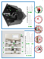
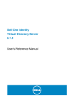
I NSTAL L ATION
RD01
MANUAL
1
2
3
4
5
WHAT’S IN THE BOX
1
Rain Director® control panel with mode indicators, programming buttons and
control valves and 230 V AC to 12 V wall adapter. Control panel measures
380mm W x 270mm H x 95mm D.
2
Cat 5 cable to connect junction box on header tank to underside of control panel.
Do Not Cut!
3
Smart header tank for roof space, including level sensors, float switch, Cat5
connection box and overflow tower. The 100 litre tank measures 600mm W x
490mm H x 500mm D.
4
Flow reducing valves (in plastic pack) for use in Torbeck float valve if mains
pressure is too great.
5
Mains electric submersible pump (must be pressure-sensitive and equipped
with non-return valve).
1
B
C
Do
N
ot
C ut Cat 5
D Refresh inlet from services - 22mm.
C Mains water inlet - 15mm.
B Rainwater inlet from pump - 22mm.
tank - 22mm.
A Refresh outlet to underground
I
‘U
Av oid
an
d in ve rte d ‘
U
Rainwater valve and removable filter.
H Mains water manual bypass valve.
cable to header tank.
n ot s u p p
ca
Mains water outlet to header tank - 15mm.
Rainwater outlet to header tank - 22mm.
G
G 12v power from wall adapter and Cat 5
F
E
KEY TO THE CONTROL PANEL AND PIPE DIAMETERS:
A
H
nds
’b
e
ga
rde
v
n ta ps
a
Services outlet - 22mm.
3
sa w t o c ut
Rainwater inlet from control unit - 22mm.
2
se
Mains water inlet from control unit - 15mm.
1
ia
1
5
4
6
M
6 Overflow straight out of
the house - 40mm.
5 Bottom level sensor.
4 Top level sensor.
KEY TO THE SMART HEADER TANK AND PIPES
3
2
ip e s
I
e
bl
a d e r ta n k
he
Do
ny
p
F
D P E ip e c u
p
ers
E
Do no
tt
D
Us
e
tu
ly
’
2
Install all pipes and equipment where protected from frost.
•
1
min. 1.2m
2
The header tank must be accessible
for maintenance. Ensure the lid is secure and kept in
place during installation. Keep dirt out!
Insulate if required.
Run all garden taps directly from the pump NOT from the header tank.
•
Locate the control unit where
the rainwater enters the
building on a wall in a frost
protected area. (at least 1.2m
below header tank)
Either plastic or copper pipe may be used.
•
The header tank must be fitted high enough to provide the pressure required for
washing machines.
•
3
4
Use pipe fittings which will permit removal
of solenoids.
Connect the rainwater outlet (E) to the
header tank (2) and mains water outlet (F)
to the header tank (1).
Connect any part of the 22mm gravity
feed piping that’s above the control unit for
services, running from the services outlet
(3) of the header tank, to the refresh inlet
(D).
Connect the refresh outlet pipe (A) back to
the rainwater underground tank, rainwater
inlet pipe (B) back to the pump , and mains
water inlet (C) (via a shut-off valve) to mains
water.
Only fit 22mm pipe or larger between the header tank and appliances. Water
should not flow upwards in any part of the piping between header tank and
appliances. Avoid U’s, inverted U’s and unnecessary sharp bends.
Take all pipes that are to be
connected to the control unit
and flush thoroughly. Ensure no
dirt will enter the valves on the
control unit.
•
Only cut the pipe using MDPE pipe cutters. Swarf caused by cutting pipe using
a saw blocks the solenoids.
Internal pipe work should be labelled as rainwater every 0.5m using label pack
supplied.
•
The header tank must be fitted at least 1.2 metres above the control unit and
highest toilet.
•
•
All pipes should be thoroughly flushed prior to connecting to the system.
•
Do not cut or modify the supplied CAT 5 cable. Only use the cable supplied by
Rainwater Harvesting Ltd. Longer cables are available upon request.
•
Install pipes to the control unit allowing sufficient movement for removal of the
solenoids.
•
Do not get any dirt into the underground tank, header tank or pipes: risk of
blockage in the solenoid valves.
•
Do not install the Rain Director in any way other than as given here and do not disassemble Rain Director components for
installation. Incorrect installation invalidates the warranty.
ESSENTIAL NOTES
3
1
9
Services Outlet
Fully fill the header tank and unscrew services cap.
Wait for all air to leave the system to eliminate
airlocks then replace cap ensuring that the black
washer under the cap is replaced.
Turn the quarter turn valve (H) back off.
5
Connect the mains outlet from the control
unit (F) to the header tank mains water inlet
(1) using 1/2 inch BSP.
Mains Water Inlet
6
Rain
let
Wate
r In
tlet
es Ou
Servic
10
t
Connect the Cat 5 cable to
connector (G) at the control unit
and similar connector at the header
tank.
2
3
Both designed to accept a 22mm push-fit fitting.
Connect the rainwater pipe to the rainwater inlet
spigot (2) and connect the gravity feed pipe to
the services outlet spigot (3).
Ove
rflow
6
11
Press the bottom two buttons to begin
commissioning sequence. Commissioning
cycle has started when the bottom light
flashes. This process may take roughly one
hour.
7
H
8
Check thoroughly for leaks at
all connections.
Use the quarter turn valve on
the control unit (H) to partially
fill the header tank.
12
Commissioning has finished when the
rainwater light and mains water light flash
alternately. Press the rainwater button to
revert the system to rain mode.
The overflow (6) must run straight out of the
house without obstruction, bends, or decreasing
pipe diameter. Use 40mm waste pipe elbow, either
solvent or compression fitting.
4
Pump
25 or 32mm rainwater pipe to
building, reduced to 22mm at
control panel.
Optional outdoor tap must be
connected to the rainwater
pipe before the control panel.
Refresh pipe output must remain
below level of control panel.
22mm refresh pipe to control
panel and underground tank.
Domestic 22 mm feed.
22 mm rainwater to header.
15 mm mains water to header.
The overflow pipe must flow
directly to the outside of the
house with minimum restriction.
NOT TO SCALE
Rainwater tank
Water is drawn from the rainwater tank to fill the
header tank. If no rainwater is available, the header
tank will automatically fill with mains water.
The water is then used around the house in toilets
and washing machines.
PLUMBING SCHEMATIC
Refreshed Water
Overflow Water
Pump
The submerged water pump
must have an independent
230V AC power supply through
an RCD protected socket.
Water Used In The House
Mains Water Supply
Rain Water Supply
COLOUR KEY
Control panel
The Rain Director® control
panel is supplied with a 12V DC
supply to plug into a normal
230V AC wall socket nearby.
The junction box on the header
tank must be wired with the Cat 5
wire provided to relay the sensor
positions to the control panel.
WIRING SCHEMATIC
Rainwater tank
Waterproof junction box (IP67).
Do not use pump cable underground.
Armoured cable inside 4” services pipe.
Cat 5 wire
5
»» Rain Mode (Normal Mode): System will use rainwater within the
home. If rainwater is not available in the underground storage tank,
the system will automatically register and switch over to mains water.
»» Mains Water Mode: Press during a dry period or hose pipe ban to
Rain Filling
Mains Water Backup
run internal appliances on mains water and conserve rainwater for
garden use.
Mains Water Mode
»» Holiday Mode: If leaving the home for a prolonged period of time
(over 1 week) press the holiday button to empty the header tank
and refill with treated mains water. This prevents water quality issues.
Holiday Mode
When the system is used again it will automatically revert back to
Rain mode. It may be sensible to flush each toilet twice to leave
treated water in the cistern and bowl.
System Refreshing
System Error
»» Refresh Function: If no activity is registered the system will
automatically refresh the water within the smart header tank
every 3 days. The system will drain the smart header tank back
to the underground tank ,and refill the smart header tank with
fresh rainwater. This guarantees high quality water with no risk of
discolouration or smells. Although the system refreshes automatically,
the user can press the button to refresh the system at any point.
Power On
Technical Support Line 01733 405 111 (opt. 3)
Problem
Probable cause
Remedy
Flashing red spanner light during
initial switch on
Both float switches in
low position
Part fill header tank (as per point 8) Check Cat 5 connection is secure.
Flashing red spanner during
commissioning
Wiring fault
Check Cat 5 connection is secure, the wire provided with the system and has not
been cut at any point.
Solid red spanner light during
commissioning
Filling fault
Check Rainwater and mains water are available to the system, repeat process 9 to
remove airlocks from the system. Clear solenoid valves (contact supplier).
Mains water or refresh solenoid
constantly open
Solenoid blocked open
Clear solenoid (contact supplier).
Mains filling light showing during
normal mode
Rainwater tank empty,
pump not functioning
Check rainwater level in underground tank. If level high refer to pump guide.
Mains filling light showing despite
rainwater working and filling first
Slow fill causing
commissioning time-out
Check/clean rain solenoid (contact supplier) recommission system
(refer to point 11).
No lights on circuit board
No power reaching PCB
board
Check power to the Control unit, contact supplier for further advice if problem
persists.
Toilets not filling/system airlocked
Water supply less than
demand
Check plumbing for obstructions, remove booster pumps, REMOVE GARDEN
TAPS DIRECT FROM HEADER TANK, repeat.
Header tank overflow to waste
Rain or Mains Solenoid
blocked open
Clear solenoid (contact supplier).
Power cut in the home
Pump & control unit not
functioning
Use the quarter turn valve (H) to bypass the system with mains water.
Poor rainwater flow into the
header tank
Rain filter blocked
Check the filter on the rain feed valve (I) and remove dirt (turn off the
pump first). Repeat after a week.
All components have been designed to comply with the UK Building Regulations and WRAS
(Water Regulations Advisory Scheme). WRAS Approval No.0912064 was awarded in December 2009.
Rainwater Harvesting Ltd. certifies that the Rain Director® is compliant with the safety requirements of the Machine Directive 89/392/EC and amendments, of
the Low Voltage Directive 73/23/EC and in the Electromagnetic Compatibility Directive 89/336/EC and amendments. The materials and manufacturing of this
product are guaranteed for 2 years from the date of purchase if the installation instructions are complied with. In the event of an apparent fault, the retailer
or installer should be contacted first. Rainwater Harvesting Ltd. declines responsibility for incidents or damage caused by negligence or by ignoring these
instructions. Installation according to this installation manual is required for manufacturers’ warranties to be valid.
All rights reserved by RainWater Harvesting Limited, © 2013. The term Rain Director® is proprietary and protected by
trade mark legislation. UK, European and Worldwide patents for the Rain Director® and certain features applied for. No
part of this document can be reproduced without our permission.
Phone 01733 405111. Email: [email protected]. www.rainwaterharvesting.co.uk
6